EP3628577A1 - Saddled vehicle - Google Patents
Saddled vehicle Download PDFInfo
- Publication number
- EP3628577A1 EP3628577A1 EP19199100.9A EP19199100A EP3628577A1 EP 3628577 A1 EP3628577 A1 EP 3628577A1 EP 19199100 A EP19199100 A EP 19199100A EP 3628577 A1 EP3628577 A1 EP 3628577A1
- Authority
- EP
- European Patent Office
- Prior art keywords
- cover
- handle
- screen
- steering handle
- saddled vehicle
- Prior art date
- Legal status (The legal status is an assumption and is not a legal conclusion. Google has not performed a legal analysis and makes no representation as to the accuracy of the status listed.)
- Granted
Links
Images





Classifications
-
- B—PERFORMING OPERATIONS; TRANSPORTING
- B62—LAND VEHICLES FOR TRAVELLING OTHERWISE THAN ON RAILS
- B62J—CYCLE SADDLES OR SEATS; AUXILIARY DEVICES OR ACCESSORIES SPECIALLY ADAPTED TO CYCLES AND NOT OTHERWISE PROVIDED FOR, e.g. ARTICLE CARRIERS OR CYCLE PROTECTORS
- B62J17/00—Weather guards for riders; Fairings or stream-lining parts not otherwise provided for
- B62J17/02—Weather guards for riders; Fairings or stream-lining parts not otherwise provided for shielding only the rider's front
- B62J17/04—Windscreens
-
- B—PERFORMING OPERATIONS; TRANSPORTING
- B62—LAND VEHICLES FOR TRAVELLING OTHERWISE THAN ON RAILS
- B62K—CYCLES; CYCLE FRAMES; CYCLE STEERING DEVICES; RIDER-OPERATED TERMINAL CONTROLS SPECIALLY ADAPTED FOR CYCLES; CYCLE AXLE SUSPENSIONS; CYCLE SIDECARS, FORECARS, OR THE LIKE
- B62K21/00—Steering devices
- B62K21/12—Handlebars; Handlebar stems
-
- B—PERFORMING OPERATIONS; TRANSPORTING
- B62—LAND VEHICLES FOR TRAVELLING OTHERWISE THAN ON RAILS
- B62K—CYCLES; CYCLE FRAMES; CYCLE STEERING DEVICES; RIDER-OPERATED TERMINAL CONTROLS SPECIALLY ADAPTED FOR CYCLES; CYCLE AXLE SUSPENSIONS; CYCLE SIDECARS, FORECARS, OR THE LIKE
- B62K2202/00—Motorised scooters
Definitions
- the present invention relates to a saddled vehicle, particularly to a saddled vehicle which includes a windscreen disposed above a handle cover that covers the center in the vehicle width direction of a steering handle.
- a conventionally known saddled vehicle including a handle cover supporting an instrument panel or a lighting device at the center in the vehicle width direction of a steering handle has a windscreen disposed above the handle cover.
- Patent Literature 1 discloses a saddled vehicle having the lower end of a right and left pair of screen stays supporting the windscreen passed through openings at the handle cover so as to be fixed to the steering handle.
- Patent Literature 1 Japanese Patent No. 6295291
- Patent Literature 1 in an attempt to improve the appearance of the screen stays formed of round pipe members, the screen stays are covered with a resin cover formed of right and left components. This disadvantageously increases the number of components and assembly steps.
- An object of the present invention is to solve the conventional problem, and to provide a saddled vehicle which includes a screen stay with improved appearance, in smaller number of components and assembly steps.
- a first aspect of the present invention provides a saddled vehicle (1) including: a steering handle (2) including a grip (43) at each of its right and left ends; a handle cover (3) covering a center in a vehicle width direction of the steering handle (2); a windscreen (4) disposed above the handle cover (3); and a screen stay (60) supporting the windscreen (4) and removably mounted on the steering handle (2).
- the screen stay (60) is an integral-molded element.
- the handle cover (3) includes a notch (80) for allowing a mount part (65) provided at a bottom end of the screen stay (60) to pass through.
- the screen stay (60) includes a flange part (64) covering the notch (80).
- the flange part (64) forms a surface continuous to the handle cover (3) and exposed at an upper part of the saddled vehicle (1).
- the handle cover (3) is formed of a front-side cover (53) on a front side and a rear-side cover (54) on a rear side.
- the notch (80) is formed at the front-side cover (53).
- the flange part (64) extends rearward to be brought into contact with the rear-side cover (54).
- the screen stay (60) is mounted from the front side on the steering handle (2).
- the mount part (65) of the screen stay (60) is a plate-like member provided with through holes (65a, 65b).
- the through holes (65a, 65b) are provided by two in number and vertically aligned with each other.
- a mount stay (73) including bolts (72) to pass through the through holes (65a, 65b) is fixed.
- a seventh aspect of the present invention further includes a top cover (46) covering an upper surface of the front-side cover (53).
- the upper surface of the front-side cover (53) is inclined rear-upward.
- the top cover (46) is provided with a bulging part (46a) covering an upper part of the notch (80) in front of the flange part (64).
- the saddled vehicle (1) is a scooter-type motorcycle including a step floor (38) for a driver to rest his/her feet.
- a saddled vehicle (1) includes: a steering handle (2) including a grip (43) at each of its right and left ends; a handle cover (3) covering a center in a vehicle width direction of the steering handle (2); a windscreen (4) disposed above the handle cover (3); and a screen stay (60) supporting the windscreen (4) and removably mounted on the steering handle (2).
- the screen stay (60) is an integral-molded element.
- the handle cover (3) includes a notch (80) for allowing a mount part (65) provided at a bottom end of the screen stay (60) to pass through.
- the screen stay (60) includes a flange part (64) covering the notch (80).
- the screen stay being an integral-molded element, the screen stay is improved in its appearance benefitting from the effect of die-cast metals or injection-molded hard resins. This also contributes to reducing the number of components of the screen stay and the number of assembly steps.
- the flange part (64) forms a surface continuous to the handle cover (3) and exposed at an upper part of the saddled vehicle (1).
- the handle cover (3) is formed of a front-side cover (53) on a front side and a rear-side cover (54) on a rear side.
- the notch (80) is formed at the front-side cover (53).
- the flange part (64) extends rearward to be brought into contact with the rear-side cover (54).
- the flange part extending rearward relative to the screen stay particularly improves the appearance of the part which is easily visible to the driver holding the steering handle.
- the screen stay (60) is mounted from the front side on the steering handle (2). This facilitates work of mounting the screen stay.
- the mount part (65) of the screen stay (60) is a plate-like member provided with through holes (65a, 65b).
- the mount part is formed of a plate-like member in which the through holes are oriented in the front-rear direction. That is, the entire screen stay can be formed using a mold assembly removed in the front-rear direction, and mounted on the steering handle from the front side.
- the through holes (65a, 65b) are provided by two in number and vertically aligned with each other.
- a mount stay (73) including bolts (72) to pass through the through holes (65a, 65b) is fixed.
- the screen stay is easily fixed by inserting the bolts fixed to the mount stay into the through holes of the mount part, and screwing nuts.
- the seventh aspect further includes a top cover (46) covering an upper surface of the front-side cover (53).
- the upper surface of the front-side cover (53) is inclined rear-upward.
- the top cover (46) is provided with a bulging part (46a) covering an upper part of the notch (80) in front of the flange part (64).
- a fastening member can be fixed from the front side of the screen stay using the notch. Covering the notch provided in front of the screen stay with the bulging part of the top cover improves also the appearance as seen in a front view. Providing a top cover without a notch for allowing the screen stay to pass through easily provides a vehicle without the windscreen.
- the saddled vehicle (1) is a scooter-type motorcycle including a step floor (38) for a driver to rest his/her feet.
- the screen stay suitable to a handle cover applied to a scooter-type motorcycle is provided.
- FIG. 1 is a left side view of a motorcycle 1 according to one embodiment of the present invention.
- the motorcycle 1 is a scooter-type saddled vehicle which includes, between a seat 28 and a steering handle 2, a step floor 38 for the driver to rest his/her feet thereon.
- the motorcycle 1 includes a vehicle body frame 35, a front wheel WF supported on the vehicle body frame 35 via front forks 10, a unit swing-type power unit P supported on the vehicle body frame 35, and a rear wheel WR supported at the rear end of the power unit P.
- the vehicle body frame 35 includes a head pipe 33, a down frame 36 extending rear-downward from the head pipe 33, a right and left pair of lower frames 13 extending rightward and leftward respectively from the bottom of the down frame 36 and then extending linearly rearward, and a right and left pair of rear frames 24 extending rear-upward integrally from the rear end of the right and left lower frames 13.
- the head pipe 33 rotatably supports a steering stem 31.
- a bottom bridge 8 supporting the right and left pair of front forks 10 is fixed.
- the steering handle 2 is mounted on an upper part of the steering stem 31.
- the front wheel WF is supported at the lower end of the front forks 10 via an axle.
- the right and left pair of lower frames 13 extends substantially horizontally rearward from the lower end of the down frame 36 as seen in a side view of the vehicle.
- the lower frames 13 support the step floor 38 and swingably pivotally support the power unit P via a link mechanism 14.
- a curved cross frame 41 projecting frontward is mounted on rising parts 40 of the right and left pair of rear frames 24, a curved cross frame 41 projecting frontward is mounted.
- a side stand 23 is swingably mounted.
- a center stand 26 is provided beneath the power unit P.
- the power unit P is of the unit-swing type, in which a continuously variable transmission 16 is integrated with the rear part of the engine.
- the continuously variable transmission 16 is disposed on the left side of the rear wheel WR.
- an air cleaner 17 connected to the air intake passage of the engine is disposed.
- a muffler exhausting the exhaust gas in the engine is disposed.
- the rear end of the power unit P is suspended from the rear frames 24 by a rear shock absorber 19.
- a radiator 95 dissipating heat from coolant for the engine is disposed above the link mechanism 14 and on the right side in the vehicle body.
- a vehicle body cover 6 as an exterior component of the motorcycle 1 includes a front cover 7 covering the front side of the head pipe 33, a right and left pair of leg shields 34 coupled to the both sides of the front cover 7, an upper floor panel 32 interposed between the right and left leg shields 34 on the rear side of the head pipe 33, an under floor panel 47 continuous to the lower end of the upper floor panel 32, and a handle cover 3 covering the central part of the steering handle 2.
- a windscreen 4 extending rear-upward as seen in a side view is disposed.
- a headlamp 37 is disposed below the front cover 7, a headlamp 37 is disposed.
- the vehicle body cover 6 further includes a right and left pair of lower covers 12 covering the right and left lower frames 13 laterally and from below, a right and left pair of rear side covers 25 covering the right and left rear frames 24 on the outer sides in the vehicle width direction, a front fender 9 covering the upper side of the front wheel WF, a rear fender 20 covering the rear upper side of the rear wheel WR, and an inner rear fender 18 covering the front upper side of the rear wheel WR.
- a tail lamp 21 is mounted on the upper rear end of the rear fender 20. Between the seat 28 and the tail lamp 21, a grab rail 29 is disposed.
- a storage compartment 30 configured to store any luggage such as a helmet or a tool is disposed below the seat 28 which is opened or closed.
- the storage compartment 30 is disposed between the right and left rear frames 24, and has its front lower end fixed to the upper part of the cross frame 41.
- the seat 28 is swingably attached at the front end of the storage compartment 30, to function as an openable lid for the storage compartment 30.
- a battery B is disposed at the substantial central part of the storage compartment 30.
- Foldable pillion steps 27 for the passenger are respectively fixed to the right and left rear frames 24.
- a fuel tank 22 is disposed below the step floor 38.
- FIG. 2 is a partial enlarged front view of the motorcycle 1.
- grips 43 for the driver to hold are mounted on the right and left ends of the steering handle 2.
- a front brake lever 44 and a rear brake lever 45 are respectively disposed.
- a position lamp 5 is disposed at the center in the vehicle width direction of the handle cover 3.
- the position lamp 5 is provided with a top cover 46 at its top edge.
- the windscreen 4 which has a rounded substantial hexagonal shape as seen in a front view is formed of, for example, colored or non-colored transparent flat plate-like hard resin.
- a right and left pair of screen stays 60 extending upward from the handle cover 3 is disposed in an inclined manner so as to increase the distance between the pair upward.
- the windscreen 4 is fixed with fastening members 50 such as bolts.
- FIG. 3 is a cross-sectional view taken along line III-III in FIG. 2 (a cross section taken along the longitudinal center).
- the handle cover 3 includes a front-side cover 53 and a rear-side cover 54 clamping the steering handle 2 from the front and rear sides.
- the central part in the vehicle width direction of the front-side cover 53 is covered with the top cover 46.
- the position lamp 5 is set in an opening provided at the front-side cover 53.
- An instrument panel 49 is interposed between the front-side cover 53 and the rear-side cover 54 at an upper level in the vehicle body.
- the steering handle 2 including right and left pair of handlebars 48 equipped with the grips 43 is fixed.
- the windscreen 4 is curved so as to protrude rearward, and inclined rearward. Between a lower end 4a of the windscreen 4 and the top cover 46, a clearance is formed in order to allow airflow caused by the vehicle driving to pass through. Allowing the airflow to pass through at the center in the vehicle width direction alleviates generation of negative pressure behind the windscreen 4.
- FIG. 4 is a partial enlarged front view of the motorcycle 1 without the windscreen 4.
- FIG. 5 is a perspective view of the handle cover 3 as seen from a right, rear upper point.
- the front-side cover 53 is shaded lighter, and the screen stays 60 are shaded darker.
- the screen stays 60 are fixed to the steering handle 2 via notches provided at the front-side cover 53 and the top cover 46.
- the top cover 46 is provided with bulging parts 46a bulging upward so as to hide the lower end of the screen stays 60 as seen from the front side.
- the windscreen 4 is provided with four through holes, with which grommets 51 formed of rubber or the like are fitted. Then, from the front side, fastening members 50 are screwed thereon. Thus, the windscreen 4 is rubber mounted on the screen stays 60.
- an idle stop switch 55 and an ignition switch 56 are disposed on the right side of the rear-side cover 54 .
- a dimmer switch 52 for the headlamp 37 On the left side of the rear-side cover 54, a D-pad 59 functioning also as a turn signal switch and a confirm button 57, and a horn switch 58 are disposed.
- the rear sides at the lower ends of the screen stays 60 extend so as to be in contact with the rear-side cover 54 and the instrument panel 49, and each form a surface continuous to the top cover 46.
- FIG. 6 is a perspective view of the right and left screen stays 60 as seen from a right, rear upper point.
- FIG. 7 is a left side view of the left one of the screen stays 60.
- the screen stays 60 have vertical symmetry.
- An elongated body part 62 of the screen stay 60 includes an upper support part 61 provided with a female screw hole 61a screwed with the fastening member 50, and a lower support part 63 provided with a female screw hole 63a.
- the lower part of the body part 62 is provided with a flange part 64 extending rearward and a mount part 65 for fixing the screen stay 60 to the steering handle 2.
- each thin plate-like flange part 64 becomes flush with the surface of the top cover 46 and exposed at an upper part of the vehicle body. This particularly improves the appearance of the part which is easily visible to the driver holding the steering handle.
- the thin plate-like mount part 65 is provided with two through holes 65a, 65b aligned in the vertical direction.
- Each of the screen stays 60 is fixed to the steering handle 2 with bolts passing through the through holes 65a, 65b.
- the plate-like part provided with the through holes 65a, 65b is vertically oriented; the flange part 64 is inclined rear-upward; and the body part 62 is inclined rearward.
- the screen stays 60 can be formed using a mold assembly removed in the front-rear direction, and mounted on the steering handle 2 from the front side.
- the through holes 65a, 65b at the mount part 65 are formed in the molding, while the female screw hole 61a at the upper support part 61 and the female screw hole 63a at the lower support part 63 are formed by machine work (removal work) after the molding.
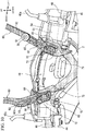
- FIG. 8 is a partial enlarged front view corresponding to the handle cover 3 in FIG. 4 without the top cover 46.
- FIG. 9 is a perspective view of the handle cover 3 in FIG. 8 as seen from a left, front upper point.
- the position lamp 5 is also not shown while a fixing member 5b for the position lamp 5 is left. Beneath the lower support parts 63 of the screen stays 60, reduced-thickness parts 66, 67 are provided for an improvement also in terms of design.
- an opening 5a for the position lamp 5 to be set in is formed.
- the position lamp 5 is mounted on the front-side cover 53 via a fixing member 5b fixed to the upper edge of the opening 5a.
- an upper surface part 53a covered with the top cover 46 is provided at an upper part of the front-side cover 53.
- an upper surface part 53a covered with the top cover 46 is provided.
- right and left pairs of rear engagement holes 70 and front engagement holes 71 for fixing the top cover 46 are formed.
- notches 80 for allowing the mount parts 65 of the screen stays 60 to pass through are formed on the outer sides in the vehicle width direction of the upper surface part 53a.
- the screen stays 60 are mounted by: inserting the mount parts 65 from above the notches 80; inserting mount bolts 72 fixed to the steering handle 2 on the through holes 65a, 65b of the mount parts 65; and screwing nuts from the front side of the mount bolts 72. This allows the screen stays 60 to be attached or removed without the necessity of removing not only the rear-side cover 54 but also the front-side cover 53.
- each mount part 65 While the upper part of each mount part 65 is disposed so as to project upward from the upper surface part 53a, it is covered with the corresponding bulging part 46a of the top cover 46. This maintains the excellent appearance. That is, the screen stays 60 are stably fixed with improved flexibility in design of the mount parts 65, with improved appearance.
- FIG. 10 is a perspective view showing the coupling structure of the screen stays 60 and the steering handle 2.
- the steering handle 2 is shaded lighter, and the screen stays 60 is shaded darker.
- a reservoir tank 90 configured to store brake fluid for the front brake is disposed.
- a reservoir tank 91 configured to store brake fluid for the rear brake is disposed.
- mount bolts 72 oriented frontward are welded.
- the mount bolts 72 and corresponding through holes 65a, 65b are vertically aligned two pieces each, an increase in the vehicle width dimension of the mount parts is prevented while coupling strength is improved.
- the screen stays 60 are fastened and tightened by the nuts screwed from the front side on the mount bolts 72 provided on the handle side.
- the screen stays 60 may be fastened and tightened by bolts screwed from the front side on nuts fixed to the handle side.
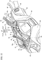
- FIG. 11 is a perspective view of the handle cover 3 in FIG. 8 without the top cover 46 as seen from a left, rear upper point.
- the steering handle 2 is shaded lighter, and the screen stays 60 are shaded darker.
- the flange part 64 provided at the screen stays 60 extends rearward to be in contact with the rear-side cover 54 and the instrument panel 49, to be integrated with the top cover 46.
- the screen stays 60 are formed of metal, the screen stays 60 present texture different from that of the top cover 46 formed of hard resin or the like. In particular, this improves the appearance of the part which is easily visible to the driver holding the steering handle.
- a top cover dispensing with the screen stays 60 presents improved appearance with its smooth surface free of the boundary with the screen stays.
- the mode of the saddled vehicle, the shape of the windscreen, the shape or material of the screen stays, the shape or material of the handle cover, the shape of the front-side cover and the rear-side cover, the type of the fastening members and the like are not limited to those in the embodiment, and various changes may be made.
- the screen stay mount structure of the present invention is applicable not only to a motorcycle, and is applicable to a saddle-ridden three-wheel or four-wheel vehicle.
Landscapes
- Engineering & Computer Science (AREA)
- Mechanical Engineering (AREA)
- Steering Devices For Bicycles And Motorcycles (AREA)
- Automatic Cycles, And Cycles In General (AREA)
Abstract
Description
- The present invention relates to a saddled vehicle, particularly to a saddled vehicle which includes a windscreen disposed above a handle cover that covers the center in the vehicle width direction of a steering handle. 2. Description of the Background
- A conventionally known saddled vehicle including a handle cover supporting an instrument panel or a lighting device at the center in the vehicle width direction of a steering handle has a windscreen disposed above the handle cover.
-
Patent Literature 1 discloses a saddled vehicle having the lower end of a right and left pair of screen stays supporting the windscreen passed through openings at the handle cover so as to be fixed to the steering handle. - Patent Literature 1: Japanese Patent No.
6295291 - In
Patent Literature 1, in an attempt to improve the appearance of the screen stays formed of round pipe members, the screen stays are covered with a resin cover formed of right and left components. This disadvantageously increases the number of components and assembly steps. - An object of the present invention is to solve the conventional problem, and to provide a saddled vehicle which includes a screen stay with improved appearance, in smaller number of components and assembly steps.
- In order to achieve the object, a first aspect of the present invention provides a saddled vehicle (1) including: a steering handle (2) including a grip (43) at each of its right and left ends; a handle cover (3) covering a center in a vehicle width direction of the steering handle (2); a windscreen (4) disposed above the handle cover (3); and a screen stay (60) supporting the windscreen (4) and removably mounted on the steering handle (2). The screen stay (60) is an integral-molded element. The handle cover (3) includes a notch (80) for allowing a mount part (65) provided at a bottom end of the screen stay (60) to pass through. The screen stay (60) includes a flange part (64) covering the notch (80).
- In a second aspect of the present invention, when the screen stay (60) is mounted on the steering handle (2), the flange part (64) forms a surface continuous to the handle cover (3) and exposed at an upper part of the saddled vehicle (1).
- In a third aspect of the present invention, the handle cover (3) is formed of a front-side cover (53) on a front side and a rear-side cover (54) on a rear side. The notch (80) is formed at the front-side cover (53). The flange part (64) extends rearward to be brought into contact with the rear-side cover (54).
- In a fourth aspect of the present invention, the screen stay (60) is mounted from the front side on the steering handle (2).
- In a fifth aspect of the present invention, the mount part (65) of the screen stay (60) is a plate-like member provided with through holes (65a, 65b).
- In a sixth aspect of the present invention, the through holes (65a, 65b) are provided by two in number and vertically aligned with each other. To the steering handle (2), a mount stay (73) including bolts (72) to pass through the through holes (65a, 65b) is fixed.
- A seventh aspect of the present invention further includes a top cover (46) covering an upper surface of the front-side cover (53). The upper surface of the front-side cover (53) is inclined rear-upward. The top cover (46) is provided with a bulging part (46a) covering an upper part of the notch (80) in front of the flange part (64).
- In an eighth aspect of the present invention, the saddled vehicle (1) is a scooter-type motorcycle including a step floor (38) for a driver to rest his/her feet.
- According to the first aspect, a saddled vehicle (1) includes: a steering handle (2) including a grip (43) at each of its right and left ends; a handle cover (3) covering a center in a vehicle width direction of the steering handle (2); a windscreen (4) disposed above the handle cover (3); and a screen stay (60) supporting the windscreen (4) and removably mounted on the steering handle (2). The screen stay (60) is an integral-molded element. The handle cover (3) includes a notch (80) for allowing a mount part (65) provided at a bottom end of the screen stay (60) to pass through. The screen stay (60) includes a flange part (64) covering the notch (80). Thus, by virtue of the screen stay being an integral-molded element, the screen stay is improved in its appearance benefitting from the effect of die-cast metals or injection-molded hard resins. This also contributes to reducing the number of components of the screen stay and the number of assembly steps.
- According to the second aspect, when the screen stay (60) is mounted on the steering handle (2), the flange part (64) forms a surface continuous to the handle cover (3) and exposed at an upper part of the saddled vehicle (1). Thus, provision of the flange part which is flush with the surface of the handle cover improves the appearance of the lower end of the screen stay when the screen stay is mounted on the steering handle.
- According to the third aspect, the handle cover (3) is formed of a front-side cover (53) on a front side and a rear-side cover (54) on a rear side. The notch (80) is formed at the front-side cover (53). The flange part (64) extends rearward to be brought into contact with the rear-side cover (54). The flange part extending rearward relative to the screen stay particularly improves the appearance of the part which is easily visible to the driver holding the steering handle.
- According to the fourth aspect, the screen stay (60) is mounted from the front side on the steering handle (2). This facilitates work of mounting the screen stay.
- According to the fifth aspect, the mount part (65) of the screen stay (60) is a plate-like member provided with through holes (65a, 65b). Thus, the mount part is formed of a plate-like member in which the through holes are oriented in the front-rear direction. That is, the entire screen stay can be formed using a mold assembly removed in the front-rear direction, and mounted on the steering handle from the front side.
- According to the sixth aspect, the through holes (65a, 65b) are provided by two in number and vertically aligned with each other. To the steering handle (2), a mount stay (73) including bolts (72) to pass through the through holes (65a, 65b) is fixed. Thus, the screen stay is easily fixed by inserting the bolts fixed to the mount stay into the through holes of the mount part, and screwing nuts. By virtue of the through holes being aligned in the vertical direction by two pieces, an increase in the vehicle width dimension of the mount part is prevented while coupling strength is improved.
- The seventh aspect further includes a top cover (46) covering an upper surface of the front-side cover (53). The upper surface of the front-side cover (53) is inclined rear-upward. The top cover (46) is provided with a bulging part (46a) covering an upper part of the notch (80) in front of the flange part (64). Thus, providing a notch at the upper surface of the inclined front-side cover, a fastening member can be fixed from the front side of the screen stay using the notch. Covering the notch provided in front of the screen stay with the bulging part of the top cover improves also the appearance as seen in a front view. Providing a top cover without a notch for allowing the screen stay to pass through easily provides a vehicle without the windscreen.
- According to the eighth aspect, the saddled vehicle (1) is a scooter-type motorcycle including a step floor (38) for a driver to rest his/her feet. Thus, the screen stay suitable to a handle cover applied to a scooter-type motorcycle is provided.
-
-
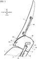
FIG. 1 is a left side view of a motorcycle according to one embodiment of the present invention. -
FIG. 2 is a partial enlarged front view of the motorcycle. -
FIG. 3 is a cross-sectional view taken along line III-III inFIG. 2 (a cross section taken along the longitudinal center). -
FIG. 4 is a partial enlarged front view of the motorcycle without a windscreen. -
FIG. 5 is a perspective view of a handle cover as seen from a right, rear upper point. -
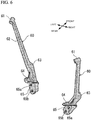
FIG. 6 is a perspective view of right and left screen stays as seen from a right, rear upper point. -
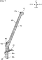
FIG. 7 is a left side view of the left one of the screen stays. -
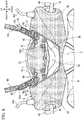
FIG. 8 is a partial enlarged front view corresponding to the handle cover inFIG. 4 without a top cover. -
FIG. 9 is a perspective view of the handle cover inFIG. 8 as seen from a left, front upper point. -
FIG. 10 is a perspective view showing a coupling structure of the screen stays and a steering handle. -
FIG. 11 is a perspective view of the handle cover inFIG. 8 without the top cover as seen from a left, rear upper point. - In the following, with reference to the drawings, a detailed description will be given of a preferred embodiment of the present invention.
FIG. 1 is a left side view of amotorcycle 1 according to one embodiment of the present invention. Themotorcycle 1 is a scooter-type saddled vehicle which includes, between aseat 28 and asteering handle 2, astep floor 38 for the driver to rest his/her feet thereon. Themotorcycle 1 includes avehicle body frame 35, a front wheel WF supported on thevehicle body frame 35 viafront forks 10, a unit swing-type power unit P supported on thevehicle body frame 35, and a rear wheel WR supported at the rear end of the power unit P. - The
vehicle body frame 35 includes ahead pipe 33, a down frame 36 extending rear-downward from thehead pipe 33, a right and left pair oflower frames 13 extending rightward and leftward respectively from the bottom of the down frame 36 and then extending linearly rearward, and a right and left pair ofrear frames 24 extending rear-upward integrally from the rear end of the right and left lower frames 13. - The
head pipe 33 rotatably supports asteering stem 31. To the lower end of thesteering stem 31, abottom bridge 8 supporting the right and left pair offront forks 10 is fixed. The steering handle 2 is mounted on an upper part of thesteering stem 31. The front wheel WF is supported at the lower end of thefront forks 10 via an axle. Thus, by the steering handle 2 steered rightward and leftward, the front wheel WF is steered rightward and leftward. - The right and left pair of
lower frames 13 extends substantially horizontally rearward from the lower end of the down frame 36 as seen in a side view of the vehicle. The lower frames 13 support thestep floor 38 and swingably pivotally support the power unit P via alink mechanism 14. On rising parts 40 of the right and left pair ofrear frames 24, acurved cross frame 41 projecting frontward is mounted. Above thelink mechanism 14, on the left one of thelower frames 13, aside stand 23 is swingably mounted. Acenter stand 26 is provided beneath the power unit P. - The power unit P is of the unit-swing type, in which a continuously
variable transmission 16 is integrated with the rear part of the engine. The continuouslyvariable transmission 16 is disposed on the left side of the rear wheel WR. Above the continuouslyvariable transmission 16, anair cleaner 17 connected to the air intake passage of the engine is disposed. On the right side of the rear wheel WR, a muffler exhausting the exhaust gas in the engine is disposed. The rear end of the power unit P is suspended from the rear frames 24 by arear shock absorber 19. Aradiator 95 dissipating heat from coolant for the engine is disposed above thelink mechanism 14 and on the right side in the vehicle body. - A
vehicle body cover 6 as an exterior component of themotorcycle 1 includes afront cover 7 covering the front side of thehead pipe 33, a right and left pair of leg shields 34 coupled to the both sides of thefront cover 7, anupper floor panel 32 interposed between the right and left leg shields 34 on the rear side of thehead pipe 33, an under floor panel 47 continuous to the lower end of theupper floor panel 32, and ahandle cover 3 covering the central part of thesteering handle 2. On the upper part of thehandle cover 3 supporting aposition lamp 5, awindscreen 4 extending rear-upward as seen in a side view is disposed. On the outer sides in the vehicle width direction of thehandle cover 3, a right and left pair of rear view mirrors 42 is disposed. Below thefront cover 7, aheadlamp 37 is disposed. - The
vehicle body cover 6 further includes a right and left pair oflower covers 12 covering the right and leftlower frames 13 laterally and from below, a right and left pair of rear side covers 25 covering the right and leftrear frames 24 on the outer sides in the vehicle width direction, afront fender 9 covering the upper side of the front wheel WF, arear fender 20 covering the rear upper side of the rear wheel WR, and an innerrear fender 18 covering the front upper side of the rear wheel WR. Atail lamp 21 is mounted on the upper rear end of therear fender 20. Between theseat 28 and thetail lamp 21, agrab rail 29 is disposed. - Below the
seat 28 which is opened or closed, astorage compartment 30 configured to store any luggage such as a helmet or a tool is disposed. Thestorage compartment 30 is disposed between the right and leftrear frames 24, and has its front lower end fixed to the upper part of thecross frame 41. Theseat 28 is swingably attached at the front end of thestorage compartment 30, to function as an openable lid for thestorage compartment 30. A battery B is disposed at the substantial central part of thestorage compartment 30. Foldable pillion steps 27 for the passenger are respectively fixed to the right and left rear frames 24. Afuel tank 22 is disposed below thestep floor 38. -
FIG. 2 is a partial enlarged front view of themotorcycle 1. On the right and left ends of thesteering handle 2, grips 43 for the driver to hold are mounted. On the front side of the right and leftgrips 43, afront brake lever 44 and arear brake lever 45 are respectively disposed. At the center in the vehicle width direction of thehandle cover 3, aposition lamp 5 is disposed. Theposition lamp 5 is provided with atop cover 46 at its top edge. - The
windscreen 4 which has a rounded substantial hexagonal shape as seen in a front view is formed of, for example, colored or non-colored transparent flat plate-like hard resin. A right and left pair of screen stays 60 extending upward from thehandle cover 3 is disposed in an inclined manner so as to increase the distance between the pair upward. To the front side of the screen stays 60, thewindscreen 4 is fixed withfastening members 50 such as bolts. -
FIG. 3 is a cross-sectional view taken along line III-III inFIG. 2 (a cross section taken along the longitudinal center). Thehandle cover 3 includes a front-side cover 53 and a rear-side cover 54 clamping the steering handle 2 from the front and rear sides. The central part in the vehicle width direction of the front-side cover 53 is covered with thetop cover 46. Theposition lamp 5 is set in an opening provided at the front-side cover 53. Aninstrument panel 49 is interposed between the front-side cover 53 and the rear-side cover 54 at an upper level in the vehicle body. To the upper end of thesteering stem 31, the steering handle 2 including right and left pair ofhandlebars 48 equipped with thegrips 43 is fixed. - The
windscreen 4 is curved so as to protrude rearward, and inclined rearward. Between alower end 4a of thewindscreen 4 and thetop cover 46, a clearance is formed in order to allow airflow caused by the vehicle driving to pass through. Allowing the airflow to pass through at the center in the vehicle width direction alleviates generation of negative pressure behind thewindscreen 4. -
FIG. 4 is a partial enlarged front view of themotorcycle 1 without thewindscreen 4.FIG. 5 is a perspective view of thehandle cover 3 as seen from a right, rear upper point. InFIGS. 4 and5 , the front-side cover 53 is shaded lighter, and the screen stays 60 are shaded darker. -
Stays 42a for the rear view mirrors 42 are fixed to the steering handle 2 via through holes provided at the front-side cover 53. The screen stays 60 are fixed to the steering handle 2 via notches provided at the front-side cover 53 and thetop cover 46. Thetop cover 46 is provided with bulgingparts 46a bulging upward so as to hide the lower end of the screen stays 60 as seen from the front side. Thewindscreen 4 is provided with four through holes, with whichgrommets 51 formed of rubber or the like are fitted. Then, from the front side,fastening members 50 are screwed thereon. Thus, thewindscreen 4 is rubber mounted on the screen stays 60. - With reference to
FIG. 5 , on the right side of the rear-side cover 54, anidle stop switch 55 and anignition switch 56 are disposed. On the left side of the rear-side cover 54, adimmer switch 52 for theheadlamp 37, a D-pad 59 functioning also as a turn signal switch and aconfirm button 57, and ahorn switch 58 are disposed. The rear sides at the lower ends of the screen stays 60 extend so as to be in contact with the rear-side cover 54 and theinstrument panel 49, and each form a surface continuous to thetop cover 46. -
FIG. 6 is a perspective view of the right and left screen stays 60 as seen from a right, rear upper point.FIG. 7 is a left side view of the left one of the screen stays 60. The screen stays 60 have vertical symmetry. Anelongated body part 62 of thescreen stay 60 includes anupper support part 61 provided with afemale screw hole 61a screwed with thefastening member 50, and alower support part 63 provided with afemale screw hole 63a. The lower part of thebody part 62 is provided with aflange part 64 extending rearward and amount part 65 for fixing thescreen stay 60 to thesteering handle 2. - As shown in
FIG. 5 , when the screen stays 60 are mounted at predetermined positions, each thin plate-like flange part 64 becomes flush with the surface of thetop cover 46 and exposed at an upper part of the vehicle body. This particularly improves the appearance of the part which is easily visible to the driver holding the steering handle. - The thin plate-
like mount part 65 is provided with two throughholes holes FIG. 7 , when thescreen stay 60 is mounted on thesteering handle 2, the plate-like part provided with the throughholes flange part 64 is inclined rear-upward; and thebody part 62 is inclined rearward. - With such a shape, the screen stays 60 can be formed using a mold assembly removed in the front-rear direction, and mounted on the steering handle 2 from the front side. The through
holes mount part 65 are formed in the molding, while thefemale screw hole 61a at theupper support part 61 and thefemale screw hole 63a at thelower support part 63 are formed by machine work (removal work) after the molding. -
FIG. 8 is a partial enlarged front view corresponding to thehandle cover 3 inFIG. 4 without thetop cover 46.FIG. 9 is a perspective view of thehandle cover 3 inFIG. 8 as seen from a left, front upper point. InFIGS. 8 and9 , theposition lamp 5 is also not shown while a fixingmember 5b for theposition lamp 5 is left. Beneath thelower support parts 63 of the screen stays 60, reduced-thickness parts - At the center in the vehicle width direction of the front-
side cover 53, anopening 5a for theposition lamp 5 to be set in is formed. Theposition lamp 5 is mounted on the front-side cover 53 via a fixingmember 5b fixed to the upper edge of theopening 5a. At an upper part of the front-side cover 53, anupper surface part 53a covered with thetop cover 46 is provided. At theupper surface part 53a inclined rear-upward, right and left pairs of rear engagement holes 70 and front engagement holes 71 for fixing thetop cover 46 are formed. - On the outer sides in the vehicle width direction of the
upper surface part 53a,notches 80 for allowing themount parts 65 of the screen stays 60 to pass through are formed. The screen stays 60 are mounted by: inserting themount parts 65 from above thenotches 80; insertingmount bolts 72 fixed to the steering handle 2 on the throughholes mount parts 65; and screwing nuts from the front side of themount bolts 72. This allows the screen stays 60 to be attached or removed without the necessity of removing not only the rear-side cover 54 but also the front-side cover 53. - While the upper part of each mount
part 65 is disposed so as to project upward from theupper surface part 53a, it is covered with the corresponding bulgingpart 46a of thetop cover 46. This maintains the excellent appearance. That is, the screen stays 60 are stably fixed with improved flexibility in design of themount parts 65, with improved appearance. - The bulging
parts 46a formed at thetop cover 46 cover from thenotches 80, which has been left open after the screen stays 60 are mounted, to ribs standing on the front side at upper parts of themount parts 65, thereby improving the appearance and reducing the air resistance. Note that, providing a top cover without thenotches 80 easily provides a vehicle without thewindscreen 4. This top cover can dispense with the bulging parts and, therefore, a further smooth surface is provided. -
FIG. 10 is a perspective view showing the coupling structure of the screen stays 60 and thesteering handle 2. InFIG. 10 , the steering handle 2 is shaded lighter, and the screen stays 60 is shaded darker. At the base of thefront brake lever 44 provided on theright handlebar 48, areservoir tank 90 configured to store brake fluid for the front brake is disposed. At the base of therear brake lever 45 provided on theleft handlebar 48, areservoir tank 91 configured to store brake fluid for the rear brake is disposed. - To the
handlebars 48 at the positions inner than the right and leftreservoir tanks bolts 72 oriented frontward are welded. Thus, by allowing themount bolts 72 fixed to the mount stays 73 to pass through the throughholes mount parts 65 to be screwed with nuts which are not shown, the screen stays 60 are easily fixed from the front side. By virtue of themount bolts 72 and corresponding throughholes - In the present embodiment, the screen stays 60 are fastened and tightened by the nuts screwed from the front side on the
mount bolts 72 provided on the handle side. Here, the screen stays 60 may be fastened and tightened by bolts screwed from the front side on nuts fixed to the handle side. -
FIG. 11 is a perspective view of thehandle cover 3 inFIG. 8 without thetop cover 46 as seen from a left, rear upper point. InFIG. 11 , similarly toFIG. 8 , the steering handle 2 is shaded lighter, and the screen stays 60 are shaded darker. - As described above, the
flange part 64 provided at the screen stays 60 extends rearward to be in contact with the rear-side cover 54 and theinstrument panel 49, to be integrated with thetop cover 46. When the screen stays 60 are formed of metal, the screen stays 60 present texture different from that of thetop cover 46 formed of hard resin or the like. In particular, this improves the appearance of the part which is easily visible to the driver holding the steering handle. Here, a top cover dispensing with the screen stays 60 presents improved appearance with its smooth surface free of the boundary with the screen stays. - The mode of the saddled vehicle, the shape of the windscreen, the shape or material of the screen stays, the shape or material of the handle cover, the shape of the front-side cover and the rear-side cover, the type of the fastening members and the like are not limited to those in the embodiment, and various changes may be made. The screen stay mount structure of the present invention is applicable not only to a motorcycle, and is applicable to a saddle-ridden three-wheel or four-wheel vehicle.
-
- 1: motorcycle (saddled vehicle)
- 2: steering handle
- 3: handle cover
- 4: windscreen
- 38: step floor
- 43: grip
- 46: top cover
- 46a: bulging part
- 53: front-side cover
- 54: rear-side cover
- 60: screen stay
- 64: flange part
- 65: mount part
- 65a, 65b: through hole of mount part
- 72: bolt
- 73: mount stay
- 80: notch
Claims (8)
- A saddled vehicle (1) comprising:a steering handle (2) including a grip (43) at each of its right and left ends;a handle cover (3) covering a center in a vehicle width direction of the steering handle (2);a windscreen (4) disposed above the handle cover (3); anda screen stay (60) supporting the windscreen (4) and removably mounted on the steering handle (2), whereinthe screen stay (60) is an integral-molded element,the handle cover (3) includes a notch (80) for allowing a mount part (65) provided at a bottom end of the screen stay (60) to pass through, andthe screen stay (60) includes a flange part (64) covering the notch (80).
- The saddled vehicle according to claim 1, wherein, when the screen stay (60) is mounted on the steering handle (2), the flange part (64) forms a surface continuous to the handle cover (3) and exposed at an upper part of the saddled vehicle (1).
- The saddled vehicle according to claim 1 or 2, wherein
the handle cover (3) is formed of a front-side cover (53) on a front side and a rear-side cover (54) on a rear side,
the notch (80) is formed at the front-side cover (53), and
the flange part (64) extends rearward to be brought into contact with the rear-side cover (54). - The saddled vehicle according to any one of claims 1 to 3, wherein the screen stay (60) is mounted from the front side on the steering handle (2).
- The saddled vehicle according to any one of claims 1 to 4, wherein the mount part (65) of the screen stay (60) is a plate-like member provided with through holes (65a, 65b).
- The saddled vehicle according to claim 5, wherein
the through holes (65a, 65b) are provided by two in number and vertically aligned with each other, and
to the steering handle (2), a mount stay (73) including bolts (72) to pass through the through holes (65a, 65b) is fixed. - The saddled vehicle according to any one of claims 1 to 6, further comprising
a top cover (46) covering an upper surface of the front-side cover (53), wherein
the upper surface of the front-side cover (53) is inclined rear-upward, and
the top cover (46) is provided with a bulging part (46a) covering an upper part of the notch (80) in front of the flange part (64). - The saddled vehicle according to any one of claims 1 to 7, wherein the saddled vehicle (1) is a scooter-type motorcycle including a step floor (38) for a driver to rest his/her feet.
Applications Claiming Priority (1)
| Application Number | Priority Date | Filing Date | Title |
|---|---|---|---|
| JP2018183022A JP6935978B2 (en) | 2018-09-27 | 2018-09-27 | Saddle-type vehicle |
Publications (2)
| Publication Number | Publication Date |
|---|---|
| EP3628577A1 true EP3628577A1 (en) | 2020-04-01 |
| EP3628577B1 EP3628577B1 (en) | 2021-05-26 |
Family
ID=68066568
Family Applications (1)
| Application Number | Title | Priority Date | Filing Date |
|---|---|---|---|
| EP19199100.9A Active EP3628577B1 (en) | 2018-09-27 | 2019-09-24 | Saddled vehicle |
Country Status (3)
| Country | Link |
|---|---|
| EP (1) | EP3628577B1 (en) |
| JP (1) | JP6935978B2 (en) |
| CN (1) | CN110949579B (en) |
Families Citing this family (1)
| Publication number | Priority date | Publication date | Assignee | Title |
|---|---|---|---|---|
| CN111976878A (en) * | 2020-09-01 | 2020-11-24 | 何鹏程 | Electric motorcycle car frame assembly of modular design |
Citations (3)
| Publication number | Priority date | Publication date | Assignee | Title |
|---|---|---|---|---|
| JP2012091705A (en) * | 2010-10-27 | 2012-05-17 | Honda Motor Co Ltd | Windshield device of saddle-riding type vehicle |
| EP2505468A2 (en) * | 2011-03-28 | 2012-10-03 | Honda Motor Co., Ltd. | Windshield device for saddle-ride type vehicles |
| JP2017065667A (en) * | 2015-09-30 | 2017-04-06 | 本田技研工業株式会社 | Screen device and vehicle |
Family Cites Families (18)
| Publication number | Priority date | Publication date | Assignee | Title |
|---|---|---|---|---|
| GB720104A (en) * | 1951-12-05 | 1954-12-15 | Metal & Plastic Compacts Ltd | Improvements in or relating to windscreens for motor cycles |
| JPS5858987U (en) * | 1981-10-16 | 1983-04-21 | 本田技研工業株式会社 | Wiper switch device for motorcycles, etc. |
| JPS59111781U (en) * | 1983-01-20 | 1984-07-27 | 本田技研工業株式会社 | Windshield mounting structure for motorcycles, etc. |
| JP3321672B2 (en) * | 1992-03-10 | 2002-09-03 | ヤマハ発動機株式会社 | Motorcycle windshield mounting structure |
| JP2606104Y2 (en) * | 1993-04-03 | 2000-09-25 | 株式会社ホンダアクセス | Windshield mounting structure for motorcycles |
| JP3059908B2 (en) * | 1995-03-22 | 2000-07-04 | 株式会社ホンダアクセス | Windshield mounting structure |
| TW590931B (en) * | 2001-03-28 | 2004-06-11 | Honda Motor Co Ltd | Front cowl supporting structure and wind shield structure for motorcycle |
| JP4397636B2 (en) * | 2003-07-07 | 2010-01-13 | ヤマハ発動機株式会社 | Windshield device for saddle-ride type vehicles |
| CN2734597Y (en) * | 2004-06-01 | 2005-10-19 | 彭长贵 | Motorcycle wind guard |
| JP4332899B2 (en) * | 2006-10-06 | 2009-09-16 | 株式会社ホンダアクセス | Windshield device for saddle-ride type vehicles |
| JP2009107562A (en) * | 2007-10-31 | 2009-05-21 | Yamaha Motor Co Ltd | Motorcycle |
| JP5335617B2 (en) * | 2009-08-27 | 2013-11-06 | 本田技研工業株式会社 | Motorcycle |
| US7946642B1 (en) * | 2009-11-05 | 2011-05-24 | Yuan-Hwen Cadtool Industrial Co., Ltd. | Motorcycle windshield assembly |
| JP2012210845A (en) * | 2011-03-30 | 2012-11-01 | Honda Access Corp | Windshield device for saddle-ride vehicle |
| JP5864483B2 (en) * | 2013-07-10 | 2016-02-17 | 本田技研工業株式会社 | Front structure of saddle-ride type vehicle |
| JP2017121922A (en) * | 2016-01-08 | 2017-07-13 | ヤマハ発動機株式会社 | Saddle riding vehicle |
| CN206107431U (en) * | 2016-09-26 | 2017-04-19 | 泰安树阳商贸有限公司 | Electric motor car deep bead with ventilation window |
| CN206511027U (en) * | 2017-02-24 | 2017-09-22 | 浙江春风动力股份有限公司 | A kind of windshield bracket |
-
2018
- 2018-09-27 JP JP2018183022A patent/JP6935978B2/en not_active Expired - Fee Related
-
2019
- 2019-09-19 CN CN201910886209.5A patent/CN110949579B/en active Active
- 2019-09-24 EP EP19199100.9A patent/EP3628577B1/en active Active
Patent Citations (4)
| Publication number | Priority date | Publication date | Assignee | Title |
|---|---|---|---|---|
| JP2012091705A (en) * | 2010-10-27 | 2012-05-17 | Honda Motor Co Ltd | Windshield device of saddle-riding type vehicle |
| EP2505468A2 (en) * | 2011-03-28 | 2012-10-03 | Honda Motor Co., Ltd. | Windshield device for saddle-ride type vehicles |
| JP2017065667A (en) * | 2015-09-30 | 2017-04-06 | 本田技研工業株式会社 | Screen device and vehicle |
| JP6295291B2 (en) | 2015-09-30 | 2018-03-14 | 本田技研工業株式会社 | Screen device and vehicle |
Also Published As
| Publication number | Publication date |
|---|---|
| JP2020050219A (en) | 2020-04-02 |
| CN110949579B (en) | 2021-07-27 |
| CN110949579A (en) | 2020-04-03 |
| JP6935978B2 (en) | 2021-09-15 |
| EP3628577B1 (en) | 2021-05-26 |
Similar Documents
| Publication | Publication Date | Title |
|---|---|---|
| JP7776552B2 (en) | motorcycle | |
| US8051938B2 (en) | Seat mounting structure for motorcycle, and motorcycle incorporating same | |
| EP1245442B1 (en) | Vehicle rear structure | |
| CN101624081B (en) | Motorcycle | |
| JP4078341B2 (en) | Body cover structure for motorcycles | |
| JP6029448B2 (en) | Saddle riding vehicle | |
| US9284006B2 (en) | Straddle type vehicle | |
| EP3628577B1 (en) | Saddled vehicle | |
| CN110015366B (en) | Case structure for saddle riding vehicle | |
| JP5932920B2 (en) | Front structure of motorcycle body cover | |
| JP5460885B2 (en) | Front structure of motorcycle | |
| JP4676281B2 (en) | Vehicle flap | |
| JP2022047384A (en) | Saddle-riding type vehicle | |
| US8506000B2 (en) | Straddle type vehicle | |
| ITTO970403A1 (en) | REAR COVER FASTENING STRUCTURE FOR A SCOOTER | |
| CN110300699B (en) | straddle vehicle | |
| JP4267714B2 (en) | Motorcycle mounting structure for motorcycles | |
| JP6083816B2 (en) | Front structure of motorcycle body cover | |
| JP4199087B2 (en) | vehicle | |
| WO2017018309A1 (en) | Saddle riding type vehicle | |
| TW200405871A (en) | Handle bar switch fitting structure of motorcycle | |
| JP6894416B2 (en) | Saddle-type vehicle | |
| JP3930101B2 (en) | Auxiliary equipment layout structure for motorcycles | |
| EP3348464B1 (en) | Muffler support structure for motorcycle | |
| JP2002104265A (en) | Scooter type motorcycle |
Legal Events
| Date | Code | Title | Description |
|---|---|---|---|
| PUAI | Public reference made under article 153(3) epc to a published international application that has entered the european phase |
Free format text: ORIGINAL CODE: 0009012 |
|
| STAA | Information on the status of an ep patent application or granted ep patent |
Free format text: STATUS: REQUEST FOR EXAMINATION WAS MADE |
|
| 17P | Request for examination filed |
Effective date: 20190924 |
|
| AK | Designated contracting states |
Kind code of ref document: A1 Designated state(s): AL AT BE BG CH CY CZ DE DK EE ES FI FR GB GR HR HU IE IS IT LI LT LU LV MC MK MT NL NO PL PT RO RS SE SI SK SM TR |
|
| AX | Request for extension of the european patent |
Extension state: BA ME |
|
| STAA | Information on the status of an ep patent application or granted ep patent |
Free format text: STATUS: EXAMINATION IS IN PROGRESS |
|
| 17Q | First examination report despatched |
Effective date: 20201015 |
|
| GRAP | Despatch of communication of intention to grant a patent |
Free format text: ORIGINAL CODE: EPIDOSNIGR1 |
|
| STAA | Information on the status of an ep patent application or granted ep patent |
Free format text: STATUS: GRANT OF PATENT IS INTENDED |
|
| INTG | Intention to grant announced |
Effective date: 20210127 |
|
| GRAS | Grant fee paid |
Free format text: ORIGINAL CODE: EPIDOSNIGR3 |
|
| GRAA | (expected) grant |
Free format text: ORIGINAL CODE: 0009210 |
|
| STAA | Information on the status of an ep patent application or granted ep patent |
Free format text: STATUS: THE PATENT HAS BEEN GRANTED |
|
| AK | Designated contracting states |
Kind code of ref document: B1 Designated state(s): AL AT BE BG CH CY CZ DE DK EE ES FI FR GB GR HR HU IE IS IT LI LT LU LV MC MK MT NL NO PL PT RO RS SE SI SK SM TR |
|
| REG | Reference to a national code |
Ref country code: GB Ref legal event code: FG4D |
|
| REG | Reference to a national code |
Ref country code: CH Ref legal event code: EP |
|
| REG | Reference to a national code |
Ref country code: DE Ref legal event code: R096 Ref document number: 602019004888 Country of ref document: DE |
|
| REG | Reference to a national code |
Ref country code: AT Ref legal event code: REF Ref document number: 1395974 Country of ref document: AT Kind code of ref document: T Effective date: 20210615 |
|
| REG | Reference to a national code |
Ref country code: IE Ref legal event code: FG4D |
|
| REG | Reference to a national code |
Ref country code: LT Ref legal event code: MG9D |
|
| REG | Reference to a national code |
Ref country code: AT Ref legal event code: MK05 Ref document number: 1395974 Country of ref document: AT Kind code of ref document: T Effective date: 20210526 |
|
| PG25 | Lapsed in a contracting state [announced via postgrant information from national office to epo] |
Ref country code: HR Free format text: LAPSE BECAUSE OF FAILURE TO SUBMIT A TRANSLATION OF THE DESCRIPTION OR TO PAY THE FEE WITHIN THE PRESCRIBED TIME-LIMIT Effective date: 20210526 Ref country code: LT Free format text: LAPSE BECAUSE OF FAILURE TO SUBMIT A TRANSLATION OF THE DESCRIPTION OR TO PAY THE FEE WITHIN THE PRESCRIBED TIME-LIMIT Effective date: 20210526 Ref country code: FI Free format text: LAPSE BECAUSE OF FAILURE TO SUBMIT A TRANSLATION OF THE DESCRIPTION OR TO PAY THE FEE WITHIN THE PRESCRIBED TIME-LIMIT Effective date: 20210526 Ref country code: BG Free format text: LAPSE BECAUSE OF FAILURE TO SUBMIT A TRANSLATION OF THE DESCRIPTION OR TO PAY THE FEE WITHIN THE PRESCRIBED TIME-LIMIT Effective date: 20210826 Ref country code: AT Free format text: LAPSE BECAUSE OF FAILURE TO SUBMIT A TRANSLATION OF THE DESCRIPTION OR TO PAY THE FEE WITHIN THE PRESCRIBED TIME-LIMIT Effective date: 20210526 |
|
| REG | Reference to a national code |
Ref country code: NL Ref legal event code: MP Effective date: 20210526 |
|
| PG25 | Lapsed in a contracting state [announced via postgrant information from national office to epo] |
Ref country code: RS Free format text: LAPSE BECAUSE OF FAILURE TO SUBMIT A TRANSLATION OF THE DESCRIPTION OR TO PAY THE FEE WITHIN THE PRESCRIBED TIME-LIMIT Effective date: 20210526 Ref country code: SE Free format text: LAPSE BECAUSE OF FAILURE TO SUBMIT A TRANSLATION OF THE DESCRIPTION OR TO PAY THE FEE WITHIN THE PRESCRIBED TIME-LIMIT Effective date: 20210526 Ref country code: PT Free format text: LAPSE BECAUSE OF FAILURE TO SUBMIT A TRANSLATION OF THE DESCRIPTION OR TO PAY THE FEE WITHIN THE PRESCRIBED TIME-LIMIT Effective date: 20210927 Ref country code: PL Free format text: LAPSE BECAUSE OF FAILURE TO SUBMIT A TRANSLATION OF THE DESCRIPTION OR TO PAY THE FEE WITHIN THE PRESCRIBED TIME-LIMIT Effective date: 20210526 Ref country code: LV Free format text: LAPSE BECAUSE OF FAILURE TO SUBMIT A TRANSLATION OF THE DESCRIPTION OR TO PAY THE FEE WITHIN THE PRESCRIBED TIME-LIMIT Effective date: 20210526 Ref country code: NO Free format text: LAPSE BECAUSE OF FAILURE TO SUBMIT A TRANSLATION OF THE DESCRIPTION OR TO PAY THE FEE WITHIN THE PRESCRIBED TIME-LIMIT Effective date: 20210826 Ref country code: IS Free format text: LAPSE BECAUSE OF FAILURE TO SUBMIT A TRANSLATION OF THE DESCRIPTION OR TO PAY THE FEE WITHIN THE PRESCRIBED TIME-LIMIT Effective date: 20210926 Ref country code: GR Free format text: LAPSE BECAUSE OF FAILURE TO SUBMIT A TRANSLATION OF THE DESCRIPTION OR TO PAY THE FEE WITHIN THE PRESCRIBED TIME-LIMIT Effective date: 20210827 |
|
| PG25 | Lapsed in a contracting state [announced via postgrant information from national office to epo] |
Ref country code: NL Free format text: LAPSE BECAUSE OF FAILURE TO SUBMIT A TRANSLATION OF THE DESCRIPTION OR TO PAY THE FEE WITHIN THE PRESCRIBED TIME-LIMIT Effective date: 20210526 |
|
| PG25 | Lapsed in a contracting state [announced via postgrant information from national office to epo] |
Ref country code: EE Free format text: LAPSE BECAUSE OF FAILURE TO SUBMIT A TRANSLATION OF THE DESCRIPTION OR TO PAY THE FEE WITHIN THE PRESCRIBED TIME-LIMIT Effective date: 20210526 Ref country code: ES Free format text: LAPSE BECAUSE OF FAILURE TO SUBMIT A TRANSLATION OF THE DESCRIPTION OR TO PAY THE FEE WITHIN THE PRESCRIBED TIME-LIMIT Effective date: 20210526 Ref country code: SK Free format text: LAPSE BECAUSE OF FAILURE TO SUBMIT A TRANSLATION OF THE DESCRIPTION OR TO PAY THE FEE WITHIN THE PRESCRIBED TIME-LIMIT Effective date: 20210526 Ref country code: CZ Free format text: LAPSE BECAUSE OF FAILURE TO SUBMIT A TRANSLATION OF THE DESCRIPTION OR TO PAY THE FEE WITHIN THE PRESCRIBED TIME-LIMIT Effective date: 20210526 Ref country code: DK Free format text: LAPSE BECAUSE OF FAILURE TO SUBMIT A TRANSLATION OF THE DESCRIPTION OR TO PAY THE FEE WITHIN THE PRESCRIBED TIME-LIMIT Effective date: 20210526 Ref country code: RO Free format text: LAPSE BECAUSE OF FAILURE TO SUBMIT A TRANSLATION OF THE DESCRIPTION OR TO PAY THE FEE WITHIN THE PRESCRIBED TIME-LIMIT Effective date: 20210526 Ref country code: SM Free format text: LAPSE BECAUSE OF FAILURE TO SUBMIT A TRANSLATION OF THE DESCRIPTION OR TO PAY THE FEE WITHIN THE PRESCRIBED TIME-LIMIT Effective date: 20210526 |
|
| REG | Reference to a national code |
Ref country code: DE Ref legal event code: R097 Ref document number: 602019004888 Country of ref document: DE |
|
| REG | Reference to a national code |
Ref country code: DE Ref legal event code: R119 Ref document number: 602019004888 Country of ref document: DE |
|
| PLBE | No opposition filed within time limit |
Free format text: ORIGINAL CODE: 0009261 |
|
| STAA | Information on the status of an ep patent application or granted ep patent |
Free format text: STATUS: NO OPPOSITION FILED WITHIN TIME LIMIT |
|
| 26N | No opposition filed |
Effective date: 20220301 |
|
| REG | Reference to a national code |
Ref country code: BE Ref legal event code: MM Effective date: 20210930 |
|
| PG25 | Lapsed in a contracting state [announced via postgrant information from national office to epo] |
Ref country code: IS Free format text: LAPSE BECAUSE OF FAILURE TO SUBMIT A TRANSLATION OF THE DESCRIPTION OR TO PAY THE FEE WITHIN THE PRESCRIBED TIME-LIMIT Effective date: 20210926 Ref country code: MC Free format text: LAPSE BECAUSE OF FAILURE TO SUBMIT A TRANSLATION OF THE DESCRIPTION OR TO PAY THE FEE WITHIN THE PRESCRIBED TIME-LIMIT Effective date: 20210526 Ref country code: AL Free format text: LAPSE BECAUSE OF FAILURE TO SUBMIT A TRANSLATION OF THE DESCRIPTION OR TO PAY THE FEE WITHIN THE PRESCRIBED TIME-LIMIT Effective date: 20210526 |
|
| PG25 | Lapsed in a contracting state [announced via postgrant information from national office to epo] |
Ref country code: LU Free format text: LAPSE BECAUSE OF NON-PAYMENT OF DUE FEES Effective date: 20210924 Ref country code: IE Free format text: LAPSE BECAUSE OF NON-PAYMENT OF DUE FEES Effective date: 20210924 Ref country code: FR Free format text: LAPSE BECAUSE OF NON-PAYMENT OF DUE FEES Effective date: 20210930 Ref country code: DE Free format text: LAPSE BECAUSE OF NON-PAYMENT OF DUE FEES Effective date: 20220401 Ref country code: BE Free format text: LAPSE BECAUSE OF NON-PAYMENT OF DUE FEES Effective date: 20210930 |
|
| REG | Reference to a national code |
Ref country code: CH Ref legal event code: PL |
|
| PG25 | Lapsed in a contracting state [announced via postgrant information from national office to epo] |
Ref country code: CY Free format text: LAPSE BECAUSE OF FAILURE TO SUBMIT A TRANSLATION OF THE DESCRIPTION OR TO PAY THE FEE WITHIN THE PRESCRIBED TIME-LIMIT Effective date: 20210526 |
|
| PG25 | Lapsed in a contracting state [announced via postgrant information from national office to epo] |
Ref country code: LI Free format text: LAPSE BECAUSE OF NON-PAYMENT OF DUE FEES Effective date: 20220930 Ref country code: HU Free format text: LAPSE BECAUSE OF FAILURE TO SUBMIT A TRANSLATION OF THE DESCRIPTION OR TO PAY THE FEE WITHIN THE PRESCRIBED TIME-LIMIT; INVALID AB INITIO Effective date: 20190924 Ref country code: CH Free format text: LAPSE BECAUSE OF NON-PAYMENT OF DUE FEES Effective date: 20220930 |
|
| PG25 | Lapsed in a contracting state [announced via postgrant information from national office to epo] |
Ref country code: MK Free format text: LAPSE BECAUSE OF FAILURE TO SUBMIT A TRANSLATION OF THE DESCRIPTION OR TO PAY THE FEE WITHIN THE PRESCRIBED TIME-LIMIT Effective date: 20210526 |
|
| GBPC | Gb: european patent ceased through non-payment of renewal fee |
Effective date: 20230924 |
|
| PG25 | Lapsed in a contracting state [announced via postgrant information from national office to epo] |
Ref country code: GB Free format text: LAPSE BECAUSE OF NON-PAYMENT OF DUE FEES Effective date: 20230924 |
|
| PG25 | Lapsed in a contracting state [announced via postgrant information from national office to epo] |
Ref country code: GB Free format text: LAPSE BECAUSE OF NON-PAYMENT OF DUE FEES Effective date: 20230924 |
|
| PG25 | Lapsed in a contracting state [announced via postgrant information from national office to epo] |
Ref country code: MT Free format text: LAPSE BECAUSE OF FAILURE TO SUBMIT A TRANSLATION OF THE DESCRIPTION OR TO PAY THE FEE WITHIN THE PRESCRIBED TIME-LIMIT Effective date: 20210526 |
|
| PGFP | Annual fee paid to national office [announced via postgrant information from national office to epo] |
Ref country code: IT Payment date: 20250820 Year of fee payment: 7 |
|
| PG25 | Lapsed in a contracting state [announced via postgrant information from national office to epo] |
Ref country code: TR Free format text: LAPSE BECAUSE OF FAILURE TO SUBMIT A TRANSLATION OF THE DESCRIPTION OR TO PAY THE FEE WITHIN THE PRESCRIBED TIME-LIMIT Effective date: 20210526 |