JP3930101B2 - Auxiliary equipment layout structure for motorcycles - Google Patents
Auxiliary equipment layout structure for motorcycles Download PDFInfo
- Publication number
- JP3930101B2 JP3930101B2 JP12757897A JP12757897A JP3930101B2 JP 3930101 B2 JP3930101 B2 JP 3930101B2 JP 12757897 A JP12757897 A JP 12757897A JP 12757897 A JP12757897 A JP 12757897A JP 3930101 B2 JP3930101 B2 JP 3930101B2
- Authority
- JP
- Japan
- Prior art keywords
- engine
- auxiliary
- tank
- auxiliary equipment
- vehicle body
- Prior art date
- Legal status (The legal status is an assumption and is not a legal conclusion. Google has not performed a legal analysis and makes no representation as to the accuracy of the status listed.)
- Expired - Fee Related
Links
Images


Description
【0001】
【発明の属する技術分野】
この発明は、自動2輪車においてエンジンと燃料タンク間の空間に補機類を配設するための構造に係り、特に2サイクルエンジンの補機類配置に好適なものに関する。
【0002】
【従来の技術】
実開昭61−91482号には、2サイクルエンジンの上方に燃料タンクを配置するとともに、燃料タンクの底部前側を斜め前方上がりに傾斜させて凹部空間を形成し、この凹部空間内へオイルタンクを配設した補機類の配置構造が示されている。
【0003】
【発明が解決しようとする課題】
ところで上記構造の場合、補機類配置用の凹部空間を形成することにより燃料タンクの容量が犠牲になり易くなる。また、この凹部空間内には、補機類としてのオイルタンクが単独で配設されるだけであり、他の補機類を配設できる余裕が無い。
【0004】
【課題を解決するための手段】
上記課題を解決するため本願発明に係る自動2輪車の補機類配置構造は、前後輪を支持する車体フレームに支持されたエンジンと、その上方に配設された燃料タンクとを備えた自動2輪車において、液体タンクを側面視で燃料タンクの下端縁よりも下方かつエンジンの上部と一部重なり、さらに平面視で車体の左右方向いずれか一側へ寄せて位置に配置するとともに、
この液体タンクの外側方を覆う側面視略楕円形の補機類カバーを車体の他側と左右一対で設けたことを特徴とする。
【0005】
このとき、前記エンジンを2サイクルエンジンとし、かつ液体タンクをオイルタンクとするとともに、
このオイルタンクは、前記燃料タンクに沿って車体の前後方向へ長く、後部には一段低く下方へ突出する副室を有し、
この副室は側面視で前記エンジンの上部後方に位置することも特徴とする。
【0006】
また、前記車体の他側に設けた補機類カバーにより側面視で覆われる位置に前記液体タンク以外の他の補機類を配設することもできる。しかもこの構成は、エンジンを2サイクルエンジンとしかつ液体タンクをオイルタンクとした場合並びにそれ以外の場合、例えば、エンジンを4サイクルエンジンとし液体タンクをラジエタ液用リザーブタンク等にする場合のいずれにも適用できる。
【0007】
さらに、前記エンジンを2サイクルエンジンとし、前記液体タンクをオイルタンクとするとともに、前記他の補機類として2サイクルエンジンの排気タイミング制御弁を駆動するための駆動手段を採用することもできる。
【0008】
さらにまた、前記液体タンクを覆う補機類カバーを本体部と補助部に2分割し、本体部表面を塗装するとともに、補助部表面を前記本体部表面よりも外観が目立たない表面に形成し、かつこの補助部に前記液体タンクの液量を目視するための点検窓を設けるようにすることもできる。
【0009】
【発明の効果】
燃料タンクとエンジン上部との間に液体タンクを配設するとともに、この液体タンクを、平面視で車体の左右方向いずれか一側へ寄せ、かつ側面視で燃料タンクの下端縁よりも下方かつ一部がエンジンの上部と重なるように配設したので、補機類である比較的容量の大きな液体タンクでも、燃料タンクの容量を犠牲にせずに配設可能になる。
【0010】
しかも、この液体タンクは、燃料タンクとエンジン上部との間でかつ車体の一側へ寄って配置されているので、本来外側方から目立ち易い位置に配設されることになり、車体の外観を犠牲にし易くなるはずである。
【0011】
しかしながら、液体タンクの外側方を左右一対の略楕円形をなす補機類カバーで覆うため、側方から見たとき液体タンクの張り出しを感じさせず、そのうえ、この補機類カバーが単なるカバーでなく、あたかもエンジンの機能部品のような外観をなして意匠的なアクセントになり、その結果、車体の外観を犠牲にしないようにできる。
【0012】
このとき、エンジンの形式として2サイクルエンジンを採用した場合には、液体タンクとして2サイクルエンジン用のオイルタンクを配設することができる。
【0013】
また、車体の液体タンクと反対側に設けられた補機類カバーによって覆われる空間を利用して、液体タンクと別の補機類を配設できるので、燃料タンクとエンジンの間の空間内へ左右方向に複数の補機類を配置可能になり、スペース効率が高くなる。
【0014】
しかも、2サイクルエンジンの場合、液体タンクをオイルタンクとし、他の補機類を2サイクルエンジンの排気タイミング制御弁を駆動するための駆動手段とすれば、これらの補機類と2サイクルエンジンとの間をそれぞれ配線及び配管し易い配置構造になる。
【0015】
さらに、液体タンクを覆う補機類カバーを本体部と補助部に2分割し、本体部のみを目立つように塗装し、補助部を外観上目立たない表面にすることにより、本体部のみを補機類カバーとして認識させることができる。
【0016】
このため、液体タンクの容量や外形寸法の大きさに関係なく補機類カバーの大きさを設定でき、車種毎に要求される意匠的に好ましい大きさの補機類カバーを設けることができるようになるので、汎用性も高くなる。
【0017】
さらに、補助部を目立たせないように設定することで、本体部を引き立たせることができ、しかも点検窓を設けることにより、補機類カバーを外すことなく液体タンクの液量を目視確認でき、しかも目立たない部位に設けることができる。
【0018】
【発明の実施の形態】
以下、図面に基づいて本願発明の一実施形態を説明する。図1は本願発明が適用された自動2輪車の全体左側面図、図2はその主要部を拡大した図であり、まず、これらの図によって全体の概略構造を説明する。
【0019】
この自動2輪車は全体として、フロントフォークを大きく傾斜させたロングホイールベースで、前後輪間の低い位置にエンジン、燃料タンク及びシートを配置したシートポジションが低いアメリカンタイプもしくはカスタムバイクの外観をなすように構成されている。
【0020】
前輪1を支持するフロントフォーク2の上部は大きく後方傾斜するとともに、その上部がボトムブリッジ3及びトップブリッジ4を介してヘッドパイプ5へ回動自在に支持されている。
【0021】
トップブリッジ4に取付けられたハンドルバー6は、一度上方へ大きく延出した後、グリップ部7が下方へ向けられ、アメリカンタイプもしくはカスタムバイクにおいて一般的なハンドル形状になっている。
【0022】
ヘッドパイプ5が前端部に取付けられた主フレーム10は、車体中心線に沿って前後方向へ配設され、前半部10aはヘッドパイプ5から緩く斜め下がりに後方へ延び、その後屈曲して略上下方向へ延びる後半部10bになっている。
【0023】
ヘッドパイプ5の下部左右からはダウンフレーム11が左右一対で斜め下方へ延び、その下端部は略水平に前後方向へ延びるロアフレーム12へ連続し、この左右のロアフレーム12の後端部から斜め上方かつ後方へリヤステイ13が左右一対をなして連続して延びている。
【0024】
左右のロアフレーム12の後端部間にはクロスパイプ12aが設けられ、このクロスパイプ12aの中間部に主フレーム10を構成する後半部10bの下端部が連結されている(図2)。
【0025】
左右のロアフレーム12の後部とリヤステイ13の下部との間を連結する略三角形状のピボットプレート14が車体の左右に対で設けられ、その中央部に後述するリヤアームのピボット部14aが設けられている。
【0026】
主フレーム10を構成する前半部10aの後端部からは、左右一対のシートレール15が斜め下がりに後方へ延び、その中間部に左右のリヤステイ13の各上部が接続されている。
【0027】
左右のシートレール15は、中間部であるリヤステイ13との接続部近傍で屈曲して略水平に後方へ延び、後述するリヤフェンダ42の外方を通過するとともに、外側面はグラブレール16で覆われている。
【0028】
このグラブレール16は、共締め部材17a及び17bにて、左右のシートレール15、並びにリヤフェンダ内へ平行して配設されている左右一対のサブフレーム18と一体化されるとともに、グラブレール16の後端部にはリヤウインカ19が支持されている。
【0029】
主フレーム10、ダウンフレーム11、ロアフレーム12、リヤステイ13及びシートレール15は車体フレームを構成し、このうち、主フレーム10、ダウンフレーム11及びロアフレーム12が車体フレーム前部をなし、ここにエンジン20が支持されている。
【0030】
エンジン20は水冷2サイクル式であるが、あたかも空冷4サイクル式のような外観になるように構成され、シリンダ部20aの左右は、空冷4サイクル式エンジンのシリンダ部側面の外観形状を模して、空冷フィン様形状等が形成されたシリンダカバー20bで覆われている。
【0031】
このエンジン20は、気化器21を介してサイドカバー22内のエアクリーナ22aから吸気され、排気管23、排気チャンバ23a並びに車体右側へ配設されたサイレンサ24を経て排気される。
【0032】
排気チャンバ23aは、図2に明らかなように、エンジン20の中央部下方を前後方向に配設され、後方へ向かって次第に拡径するダイバージョン部23bと、最大径で一定するストレート部23c及び後方へ向かって次第に縮径するコーン状のコンバージョン部23dで構成されている。
【0033】
排気チャンバ23aの軸心部には、前側が小径で後側が大径となるよう二段に径が変化する二段触媒筒23eが前後方向へ長く配設され、その表面には触媒が予め坦持され、二段触媒筒23eの内外を通過する際に接触する比較的高温の排気ガスを浄化するようになっている。
【0034】
ストレート部23cの上部にはクロスパイプ12aを逃げる湾曲部23fが形成されるとともに、後端部近傍の側面からはテールパイプ23gが分枝して車体右側へ延び、その後端部がサイレンサ24へ接続しており、このようにすることで排気チャンバ23aのセッテイング自由度を高めている。
【0035】
このテールパイプ23gの右側面は外観面がメッキ処理された排気サイドカバー23hで覆われ、車体右側方から見たときあたかもサイレンサ24がコンバージョン部23dと一体になって連続しているかのような外観を呈するようになっている。
【0036】
符号25はクランクケース、26は出力スプロケットであり、この出力スプロケット26によりチエーン27及びドリブンスプロケット28を介して後輪29が駆動される。この後輪29は円板状のデイッシュホイールを備えている。
【0037】
後輪29は、リヤアーム30の後端部へ支持され、このリヤアーム30は左右一対のアーム部30aと、その各前端部を連結するクロス部30bからなり、このクロス部30bがピボットプレート14のピボット部14aに両端を支持されるピボット軸14b(図2)を介して上下方向へ揺動自在に軸着されている。
【0038】
また、図2中にピボットプレート14の一部を切り欠いて示すように、主フレーム10の後半部10bのうちクロス部30b近傍部分は、前方へ湾曲する凹部10cをなし、後半部10bが車体中央部に設けられていても、クロス部30bを後半部10bと干渉せずに左右方向へ連続して設けることができるようになっている。
【0039】
リヤアーム30の前部側における左右のアーム部30a間に形成された空間を利用してラジエタ用リザーブタンク31が側面視でリヤアーム30のアーム部30aと重なるように配設され、その上方には大部分をサイドカバー22に覆われたバッテリ32が配設され、さらに、リヤアーム30のアーム部30a後部とリヤステイ13の上部間に緩衝器33が取付けられている。
【0040】
主フレーム10上にはアメリカンタイプもしくはカスタムバイクにおいて一般的である涙滴形の燃料タンク34が支持され、その上面前部にはメーターケース35が設けられ、ここにスピードメーターなどの各種メーター類36が取付けられ、その後部には燃料タンクの注入口キャップ34dの頭部が突出している。
【0041】
燃料タンク34の下部左右には補機類カバー37が取付けられ、これら左右の補機類カバー37は樹脂で形成されかつ表面が銀色にメッキされており、燃料タンク34の下方に位置するシリンダカバー20bの各上部側面まで覆い、あたかも金属風エアークリーナーのように見える外観になっている。
【0042】
燃料タンク34の後方には段付きシート38がシートレール15上に支持され、この段付きシート38は後部が一段高くなって同乗者用シート39をなすダブルシートになっている。
【0043】
このシート38はシートポジションが低くなるように後輪29近傍の低い位置へ配設され、前述のハンドルバー6及び燃料タンク34の形状とともに、アメリカンタイプもしくはカスタムバイクにおいて一般的な、特徴のある車体外観を形成している。
【0044】
同乗者用シート39の後方には、パイプ部材を略アーチ状に形成したリヤグリップ40が上下方向へ配設され、その下端部が連結されたリヤグリップ基部41はリヤフェンダ42の外側を通ってシートレール15の後端部に支持されている。
【0045】
リヤフェンダ42は左右のシートレール15間に入って支持されるとともに、後端部にはテールライト43及びマッドガード44等が配設され、これらはリヤフェンダ42内側のサブフレーム18に支持されている。
【0046】
符号45はヘッドパイプ5、主フレーム10の前半部10a及びダウンフレーム11で形成される空間を覆う左右一対のガセット、46は補機類カバー37に覆われたオイルタンク、47はオイルポンプであり、インテークマニホールド近傍に取付けられて上方へ延びるステー48に支持されたソレノイドバルブ49へ接続している。
【0047】
50は燃料コック、51は気化器21の下流側にある吸入管へ接続されている吸気チャンバ、52はラジエタ、52aは水ポンプである。
【0048】
53はシフトペダル、54は車体右側のブレーキペダルであり、これらは、エンジン20の下部前方に相当する位置に設けられ、運転者が足を前方へ投げ出すアメリカンタイプもしくはカスタムバイクの乗車姿勢をとれるようになっている。
【0049】
ブレーキペダル54は、フロントステップ55近傍に軸支され、ロアフレーム12の下方へ長さ方向を前後方向に向けて配設されたマスターシンリンダ56を介してリヤブレーキキャリパ57を作動するようになっている。
【0050】
また、車体左側のロアフレーム12の中間部にはサイドスタンド58(図1)が起伏自在に設けられ、リヤステイ13にはステップホルダ59を介してリヤステップ59aが取付けられている。
【0051】
次に、補機類の配置構造をより詳細に説明する。図3は燃料タンク回りの外観左側面図、図4はその平面図(メーターケース省略)、図5は補機類支持ブラケット回りの平面図、図6はその左側面図(補機類カバー省略)、図7は液体タンク側の補機類カバーにおける本体部と補助部の連結構造を示す図、図8はヒューズボックスの支持構造を示す概略断面図である。
【0052】
これらの図において、燃料タンク34は略鞍型をなすように、左右の側部が垂下して左室34L及び右室34Rをなし、さらにこれらを連通して中央上部室34cが形成されている。
【0053】
図4に明らかなように、燃料タンク34の前部中央は前方から後方へ平面視略U字状に入り込む湾入部60が形成され、この湾入部60によって、中央上部室34cの前方かつ左室34L及び右室34Rの間に補機類配設用の空間61が形成されている。
【0054】
この湾入部60の上方はメーターケース35によって覆われ、メーターケース35に支持されている計器類36の一部が、その下部を空間61内へ突出させて配設されることにより、燃料タンク上方への突出量を少なくしている。
【0055】
また、この空間61内には、左室34L側の左ブラケット62と、右室34R側の右ブラケット63並びにこれら両ブラケットを連結するクロスパイプ64等で構成され補機類支持部材65が収容されている。
【0056】
クロスパイプ64の中央部は、車体取付用ブラケット66において、主フレーム10とダウンフレーム11を連結する補強パイプ57(図1、2)側のステー(図示を省略)と結合することにより、車体フレームの一部を構成する補強パイプ57へ吊り下げ支持されている。
【0057】
図5に最も明らかなように、左ブラケット62には、オイルタンク46がラバーマウント68、69を介して吊り下げ支持され、かつクロスパイプ64から垂下するステー70の下端部に取付けられた下側ブラケット71に底部を支持されている。
【0058】
この下側ブラケット71の一端部には穴72が形成され、ここに嵌合されたマウントラバー72aに、オイルタンク46の底部から下方へ一体に突出形成された突起73が差し込まれて位置決めされている。
【0059】
図4に明らかなように、オイルタンク46は平面視で湾入部60よりも左側に寄った位置で、燃料タンク34の頂部左側とほぼ重なるように前後方向へ長く配設され、前端部には注入口74が前方へ突出し、その先端にキャップ75が取付けられでいる。
【0060】
図3に明らかなように、オイルタンク46は側面視で燃料タンク34の下端縁より下方かつエンジン20を構成するシリンダヘッド20a及びこれを覆うシリンダカバー20bの上部と重なるように側方へ張り出している。
【0061】
シリンダ部20aを構成するシリンダ20cには、掃気通路20dと排気通路20eが形成され、排気ポート20fの近傍にはその上部を開閉する排気デバイス20gがプーリー20hにより回動自在に設けられている。
【0062】
プーリー20hは後述する排気デバイス駆動手段により回動され、これと一体に排気デバイス20gが回動すると、排気ポート20fの高さを変化させて排気タイミングを制御するようになっている。
【0063】
図3中の符号、20iはピストンでありシリンダ20c内を往復することにより掃気ポート20j及び排気ポート20fを開閉する。20kは半球型の燃焼室、20mはシリンダヘッド、20nは点火プラグである。
【0064】
図6に明らかなように、オイルタンク46の後部は一段低く下方へ突出する副室76をなし、この内部にオイルレベルスイッチ77が設けられ、かつ副室76の底部からはジョイント78が下方へ延出し、エンジンのオイルポンプ47(図2)へ連結されている。
【0065】
図2に示すように、オイルの供給経路は、オイルポンプ47からオイル供給量を制御するソレノイドバルブ49を介して気化器21の下流部へ適量を供給するとともに、過剰分はオイルタンク46の注入口74の近傍部へ戻されるようになっている。
【0066】
図3及び図7に示すように、オイルタンク46の外側方は左室34Lの下端縁部へ後述する構造で取付けられている補機類カバー37L(以下、左右を区別する必要があるときは、参照符号37に右側のときR、左側のときLを添えるものとする)によって覆われ、かつ補機類カバー37Lはオイルタンク46の本体部分を覆う本体部80と副室76を覆う補助部81に2分割されている。
【0067】
本体部80と補助部81はそれぞれプラスチック等適宜材料を用いて形成され、本体部80は表面によく目立つような銀色メッキ処理による装飾的塗装が施され、あたかもアメリカンタイプの自動2輪車もしくはカスタムバイクによく見られるエアクリーナケースカバーのようなエンジン機能部品の印象を与えている。
【0068】
補助部81は本体部80を引き立たせるように、例えば、暗色塗装などのあまり目立たないような表面への処理が施され、あたかも本体部80と全く別機能部品であるかのような印象を与えるとともに、側面に副室76の残存液量を目視するための点検用窓82が形成されている。この位置は黙視確認が容易でかつ外観上目立ちにくい場所に選定される。
【0069】
一方、図4及び5に示すように、空間61のうち燃料タンク34の右室34R側内には、右ブラケット63の近傍部分において、補機類である排気デバイス駆動手段83及びヒューズボックス84がクロスパイプ64へ支持されている。
【0070】
図5に明らかなように、排気デバイス駆動手段83は、エンジン20の排気タイミングを制御する排気デバイスを駆動するためのものであり、本体ケース85内へ収容されているステップモータにより駆動されるプーリー86と、このプーリー86により操作されるワイヤ87を備えている。
【0071】
このワイヤ87の先端は、図3に示すようにプーリー20hへ連結し、排気デバイス駆動手段83のステップモータによりプーリー20hを介して排気デバイス20gを回動させるようになっている。
【0072】
図5に明らかなように、排気デバイス駆動手段83の本体ケース85は、その前部に突出形成された取付部88、89でそれぞれマウントラバー90を介してクロスパイプ64上へ固定されたブラケット91へ取付けられる。
【0073】
このとき、取付部88側は、ブラケット91から一体に突出するピン92にマウントラバー90の穴部を差し込むだけとし、取付部89側で、ボルト93を用いて予めブラケット91側に取付けられているナットと締結される(図6参照)。
【0074】
図6に明らかなように、ヒューズボックス84は、クロスパイプ64に取付けられているブラケット94へマウントラバー94aを介してボルト95及びブラケット94のウエルドナット94bにより取付けられたステー96へ係合支持されるようになっている。
【0075】
図8はこの係合支持構造を説明するための模式断面図であり、ステー96の先端に形成されたレール状部97の中に、ヒューズボックス84の外側面へ突出形成された略T字状断面の突部98を差し込むことにより、ヒューズボックス84がステー96へ迅速支持される。
【0076】
左右のブラケット62、63は、図5及び図6に示すように、それぞれ立壁部100を備え、これら立壁部100の各側面に差し込み穴101をそれぞれ前後に設け、これらの差し込み穴101にリング状の縁ゴム102を嵌合してある。
【0077】
この、縁ゴム102に囲まれた差し込み穴101内に、補機類カバー37L、37Rにおける各上部内側の縁部前後から内方へ突出する突片103をそれぞれ差し込むことにより防振的に取付けられる。
【0078】
なお、図7及び図6に示すように、補機類カバー37Lの本体部80は、その下部中央の通し穴104をブラケット71の端部に形成されている取付部105に重ね、その裏側に設けたナット106へネジ107で止められている。
【0079】
また、補助部81と本体部80の接合部における取付は、補助部81に形成された外方へ屈曲する縁部108を、本体部80に形成されている内方へ屈曲するフランジ109の内側へ重ね、ネジ110とナット111で結合されている。
【0080】
次に、本実施形態の作用を説明する。燃料タンク34とエンジン20上部との間にオイルタンク46を配設するとともに、このオイルタンク46を、平面視で車体左側へ寄せ、かつ側面視で燃料タンク34の下端縁寄りも下方でかつ一部がエンジン20のシリンダ20a並びにそのシリンダカバー20bの上部と重なるように配設したので、2サイクルエンジンに必要な補機類の一つである比較的容量の大きなオイルタンク46でも、燃料タンク34の容量を犠牲にせずに配設可能になる。
【0081】
しかも、オイルタンク46は、燃料タンク34とエンジン20の間へ位置するとともに、その一部が車体の一側へ張り出すことにより、外側方から目立ち易い配置になっているが、この部分は略楕円形の補機類カバー37Lで覆われるため、側方から見たときオイルタンク46の張り出しを感じさせないようにできる。
【0082】
そのうえ、補機類カバー37Rをオイルタンク46の配設側と反対の車体右側に設けてあるから、補機類カバー37L,37Rが外観上一部品をなし、かつ表面が銀色メッキされていることもあって、単なるカバーでなくあたかもエアクリーナカバーの如きエンジンの機能部品のように見えるので、補機類カバー37L,37Rを意匠的なアクセントに利用でき、その結果、オイルタンク46を配置しても車体の外観を犠牲にしないようにできる。
【0083】
また、オイルタンク46と反対側に設けられた補機類カバー37Rで覆われた空間61を利用して、オイルタンク46と別の補機類である排気デバイス駆動手段83及びヒューズボックス84を配設できるので、燃料タンク34とエンジン20の間の空間61内へ左右方向に複数の補機類を配置可能になり、スペース効率が高くなる。
【0084】
しかも、2サイクル式のエンジン20に対して、オイルタンク46、排気デバイス駆動手段83及びヒューズボックス84をエンジン20の上部近傍へ横並びに配設したので、排気デバイス駆動手段83とシリンダ20aの排気管接続部近傍及びオイルタンク46とその下方のオイルポンプ等との間で配線及び配管し易い配置構造になる。
【0085】
さらに、オイルタンク46を覆う補機類カバー37Lを本体部80と補助部81に2分割し、本体部80のみを目立つように塗装し、補助部81を目立たないようにすることにより、本体部80のみを補機類カバーとして認識させることができる。
【0086】
このため、オイルタンク46の容量や外形寸法の大きさに関係なく補機類カバーの大きさを設定できるので、車種毎に要求される意匠的に好ましい大きさの補機類カバーを意匠優先で設けることができ、そのうえ汎用性も高くなる。
【0087】
さらに、補助部81を目立たせないように設定することで、本体部80を引き立たせることができ、しかも点検窓82を設けることにより、補機類カバー37Lを外すことなくオイルタンク46の液量を目視確認でき、しかも外観上あまり目立たない部位に設けることができる。
【0088】
また、排気デバイス駆動手段83をなす本体ケース85の取付けにおいて、2ケ所の取付部88、89のうち一方の取付部88をピン92による係合構造とし、残りの取付部89で1ケ所のみ締結するようにしたので、着脱作業が迅速になり組付性が向上する。
【0089】
同様に、ヒューズボックス84も一体に形成された突部98を、ステー96の先端に形成されたレール状部97へ差し込むだけで簡単に支持できるから、着脱作業が迅速になり、組付性が向上する。
【0090】
なお、本願発明は上記実施形態に限定されず種々に変形可能である。例えば、エンジンは4サイクルエンジンであってもよく、オイルタンクは各種の液体を収容した液体タンクに代えることができ、この場合、冷却水のリザーブタンク等であってもよい。
【図面の簡単な説明】
【図1】本願発明が適用された自動2輪車の左側面図
【図2】その要部を拡大した図
【図3】燃料タンク回りの外観左側面図
【図4】その平面図
【図5】補機類支持ブラケット回りの平面図
【図6】その左側面図
【図7】補機類カバーにおける本体部と補助部の連結構造を示す図
【図8】ヒューズボックスの支持構造を示す概略断面図
【符号の説明】
20:エンジン、34:燃料タンク、37L・37R:補機類カバー、46:オイルタンク、61:空間、65:補機類支持部材、80:本体部、81:補助部、82:点検窓、83:排気デバイス駆動手段[0001]
BACKGROUND OF THE INVENTION
The present invention relates to a structure for arranging auxiliary equipment in a space between an engine and a fuel tank in a motorcycle, and more particularly to a structure suitable for arranging auxiliary equipment of a two-cycle engine.
[0002]
[Prior art]
In Japanese Utility Model Laid-Open No. 61-91482, a fuel tank is disposed above the two-cycle engine, and a concave space is formed by inclining the front side of the bottom of the fuel tank obliquely upward, and the oil tank is placed in the concave space. The arrangement structure of the auxiliary equipment arranged is shown.
[0003]
[Problems to be solved by the invention]
By the way, in the case of the above structure, the capacity of the fuel tank is easily sacrificed by forming the recessed space for arranging auxiliary equipment. Further, in this recess space, only an oil tank as an auxiliary machine is provided alone, and there is no room for arranging other auxiliary machines.
[0004]
[Means for Solving the Problems]
In order to solve the above problems, an auxiliary machinery arrangement structure for a motorcycle according to the present invention includes an engine supported by a vehicle body frame that supports front and rear wheels, and a fuel tank disposed above the engine. In a two-wheeled vehicle, the liquid tank is located below the lower end edge of the fuel tank in a side view and partially overlaps with the upper part of the engine, and is further moved to one side in the left-right direction of the vehicle body in a plan view.
Auxiliary covers that are substantially oval in side view and cover the outside of the liquid tankThe other sideAnd a pair of left and right.
[0005]
At this time, the engine is a two-cycle engine and the liquid tank is an oil tank.With
This oil tank is long in the front-rear direction of the vehicle body along the fuel tank, and has a sub chamber that protrudes downwardly at the rear part,
The sub chamber is also located at the upper rear of the engine in a side view.
[0006]
In addition, auxiliary equipment other than the liquid tank may be disposed at a position covered in a side view by an auxiliary equipment cover provided on the other side of the vehicle body. In addition, this configuration is used both when the engine is a two-cycle engine and the liquid tank is an oil tank and in other cases, for example, when the engine is a four-cycle engine and the liquid tank is a radiator liquid reserve tank or the like. Applicable.
[0007]
Further, the engine may be a two-cycle engine, the liquid tank may be an oil tank, and a driving means for driving an exhaust timing control valve of the two-cycle engine may be employed as the other auxiliary equipment.
[0008]
Furthermore, the auxiliary equipment cover that covers the liquid tank is divided into two parts, a main body part and an auxiliary part, and the surface of the main body part is painted, and the auxiliary part surface is formed on a surface that is less noticeable than the main body part surface, In addition, an inspection window for visually checking the amount of liquid in the liquid tank may be provided in the auxiliary portion.
[0009]
【The invention's effect】
A liquid tank is disposed between the fuel tank and the upper part of the engine, and the liquid tank is moved to one of the left and right sides of the vehicle body in a plan view and lower than the lower end edge of the fuel tank in a side view. Since the part is disposed so as to overlap the upper part of the engine, even a liquid tank having a relatively large capacity, which is an auxiliary machine, can be disposed without sacrificing the capacity of the fuel tank.
[0010]
Moreover, since the liquid tank is disposed between the fuel tank and the upper part of the engine and closer to one side of the vehicle body, the liquid tank is disposed at a position that is inherently conspicuous from the outside, so that the appearance of the vehicle body is improved. Should be easy to sacrifice.
[0011]
However, since the outer side of the liquid tank is covered with a pair of left and right auxiliary devices that form an ellipse, the liquid tank does not feel overhanging when viewed from the side. However, it looks as if it were a functional part of the engine, resulting in a design accent. As a result, the appearance of the vehicle body can be prevented from being sacrificed.
[0012]
At this time, when a two-cycle engine is adopted as the engine type, an oil tank for the two-cycle engine can be provided as a liquid tank.
[0013]
In addition, since the liquid tank and another auxiliary machine can be arranged using the space covered by the auxiliary machine cover provided on the opposite side of the vehicle body from the liquid tank, the space between the fuel tank and the engine can be arranged. A plurality of auxiliary machines can be arranged in the left-right direction, and space efficiency is increased.
[0014]
In addition, in the case of a two-cycle engine, if the liquid tank is an oil tank and the other auxiliary devices are driving means for driving the exhaust timing control valve of the two-cycle engine, these auxiliary devices and the two-cycle engine It becomes an arrangement structure in which wiring and piping are easy to connect between each.
[0015]
Furthermore, the auxiliary equipment cover that covers the liquid tank is divided into two parts, the main body and the auxiliary part, and only the main part is painted so that it is inconspicuous. It can be recognized as a kind cover.
[0016]
For this reason, the size of the auxiliary equipment cover can be set regardless of the capacity of the liquid tank and the size of the outer dimensions, and the auxiliary equipment cover having a design-preferred size required for each vehicle type can be provided. Therefore, versatility is also improved.
[0017]
Furthermore, by setting so that the auxiliary part does not stand out, the main body part can be emphasized, and by providing an inspection window, the liquid amount of the liquid tank can be visually confirmed without removing the auxiliary equipment cover, In addition, it can be provided in an inconspicuous part.
[0018]
DETAILED DESCRIPTION OF THE INVENTION
Hereinafter, an embodiment of the present invention will be described with reference to the drawings. FIG. 1 is an overall left side view of a motorcycle to which the present invention is applied, and FIG. 2 is an enlarged view of its main part. First, the overall schematic structure will be described with reference to these drawings.
[0019]
The motorcycle as a whole has a long wheelbase with a greatly inclined front fork, an American type or a car with a low seat position where the engine, fuel tank and seat are placed at a low position between the front and rear wheels.TheIt is configured to make the appearance of a tom bike.
[0020]
The upper portion of the
[0021]
The handle bar 6 attached to the top bridge 4 extends greatly upward once, and then the grip portion 7 is directed downward.TheIt has a common handle shape for tom bikes.
[0022]
The
[0023]
A pair of left and right down frames 11 extend diagonally downward from the left and right sides of the lower portion of the head pipe 5, and lower ends thereof continue to a
[0024]
A
[0025]
A pair of substantially
[0026]
A pair of left and right seat rails 15 extend obliquely downward and rearward from the rear end of the
[0027]
The left and right seat rails 15 bend in the vicinity of the connecting portion with the
[0028]
The
[0029]
The
[0030]
Although the
[0031]
The
[0032]
As is apparent from FIG. 2, the
[0033]
A two-
[0034]
A
[0035]
The right side surface of the
[0036]
Reference numeral 25 denotes a crankcase, and 26 denotes an output sprocket. The
[0037]
The
[0038]
Further, as shown in FIG. 2 with a part of the
[0039]
Using a space formed between the left and
[0040]
On the
[0041]
Auxiliary machinery covers 37 are attached to the lower left and right sides of the
[0042]
A stepped
[0043]
The
[0044]
Behind the
[0045]
The
[0046]
[0047]
50 is a fuel cock, 51 is an intake chamber connected to an intake pipe downstream of the
[0048]
53 is a shift pedal, and 54 is a brake pedal on the right side of the vehicle body. These are provided at positions corresponding to the lower front of the
[0049]
The
[0050]
Further, a side stand 58 (FIG. 1) is provided to be raised and lowered at an intermediate portion of the
[0051]
Next, the arrangement structure of auxiliary machinery will be described in more detail. 3 is a left side view of the external appearance around the fuel tank, FIG. 4 is a plan view thereof (meter case omitted), FIG. 5 is a plan view around the auxiliary equipment support bracket, and FIG. 6 is a left side view thereof (auxiliary equipment cover omitted). 7 is a diagram showing a connecting structure of the main body part and the auxiliary part in the auxiliary equipment cover on the liquid tank side, and FIG. 8 is a schematic sectional view showing a support structure of the fuse box.
[0052]
In these drawings, the
[0053]
As is apparent from FIG. 4, a bay entrance 60 is formed in the front center of the
[0054]
The upper part of the bay portion 60 is covered with the
[0055]
Also, in this
[0056]
The central portion of the
[0057]
5, the
[0058]
A
[0059]
As is apparent from FIG. 4, the
[0060]
As is apparent from FIG. 3, the
[0061]
A
[0062]
The
[0063]
Reference numeral 20i in FIG. 3 denotes a piston, which opens and closes the scavenging
[0064]
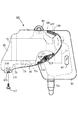
Figure6As can be seen, the rear portion of the
[0065]
As shown in FIG. 2, the oil supply path supplies an appropriate amount from the oil pump 47 to the downstream portion of the
[0066]
As shown in FIGS. 3 and 7, the outer side of the
[0067]
The
[0068]
The
[0069]
4 and 5, on the
[0070]
As is apparent from FIG. 5, the exhaust device driving means 83 is for driving an exhaust device that controls the exhaust timing of the
[0071]
The tip of the
[0072]
As apparent from FIG. 5, the
[0073]
At this time, the
[0074]
As apparent from FIG. 6, the
[0075]
FIG. 8 is a schematic cross-sectional view for explaining this engagement support structure. In the rail-shaped
[0076]
Left and
[0077]
Into the
[0078]
As shown in FIGS. 7 and 6, the
[0079]
In addition, the attachment at the joint portion between the
[0080]
Next, the operation of this embodiment will be described. An
[0081]
In addition, the
[0082]
In addition, since the
[0083]
Further, the exhaust device driving means 83 and the
[0084]
Moreover, since the
[0085]
Furthermore, the
[0086]
For this reason, since the size of the auxiliary machinery cover can be set regardless of the capacity of the
[0087]
Furthermore, by setting the
[0088]
In addition, when attaching the
[0089]
Similarly, the
[0090]
In addition, this invention is not limited to the said embodiment, A various deformation | transformation is possible. For example, the engine may be a four-cycle engine, and the oil tank may be replaced with a liquid tank containing various liquids. In this case, a cooling water reserve tank or the like may be used.
[Brief description of the drawings]
FIG. 1 is a left side view of a motorcycle to which the present invention is applied.
FIG. 2 is an enlarged view of the main part.
[Figure 3] External left side view around fuel tank
FIG. 4 is a plan view thereof.
[Fig. 5] Plan view around auxiliary equipment support bracket
Fig. 6 Left side view
FIG. 7 is a view showing a connecting structure of a main body part and an auxiliary part in an auxiliary equipment cover
FIG. 8 is a schematic sectional view showing a support structure of a fuse box
[Explanation of symbols]
20: Engine, 34: Fuel tank, 37L / 37R: Auxiliary machinery cover, 46: Oil tank, 61: Space, 65: Auxiliary machinery supporting member, 80: Main body portion, 81: Auxiliary portion, 82: Inspection window, 83: Exhaust device driving means
Claims (4)
液体タンクを、側面視で燃料タンクの下端縁よりも下方かつエンジンの上部と一部重なりさらに平面視で車体の左右方向いずれか一側へ寄せた位置に配置するとともに、
この液体タンクの外側方を覆う側面視略楕円形の補機類カバーを車体の他側と左右一対で設け、
前記エンジンが2サイクルエンジンであるとともに前記液体タンクがオイルタンクであり、
このオイルタンクは、前記燃料タンクに沿って車体の前後方向へ長く、後部には一段低く下方へ突出する副室を有し、
この副室は側面視で前記エンジンの上部後方に位置する、
ことを特徴とする自動2輪車の補機類配置構造。In a motorcycle including an engine supported by a vehicle body frame that supports front and rear wheels, and a fuel tank disposed above the engine,
The liquid tank is disposed at a position below the lower edge of the fuel tank in a side view and partially overlapping with the upper part of the engine and further toward one side of the vehicle body in a plan view.
A pair of left and right auxiliary equipment covers that are substantially oval in side view covering the outside of the liquid tank are provided on the other side of the vehicle body ,
The engine is a two-cycle engine and the liquid tank is an oil tank;
This oil tank is long in the front-rear direction of the vehicle body along the fuel tank, and has a sub chamber that protrudes downwardly at the rear part,
This sub-chamber is located at the upper rear of the engine in a side view,
An auxiliary equipment arrangement structure of a motorcycle characterized by the above.
Priority Applications (2)
| Application Number | Priority Date | Filing Date | Title |
|---|---|---|---|
| JP12757897A JP3930101B2 (en) | 1997-05-16 | 1997-05-16 | Auxiliary equipment layout structure for motorcycles |
| CN98107321A CN1091710C (en) | 1997-05-16 | 1998-04-22 | Auxiliary part's installation for motor bicycle |
Applications Claiming Priority (1)
| Application Number | Priority Date | Filing Date | Title |
|---|---|---|---|
| JP12757897A JP3930101B2 (en) | 1997-05-16 | 1997-05-16 | Auxiliary equipment layout structure for motorcycles |
Publications (2)
| Publication Number | Publication Date |
|---|---|
| JPH10316071A JPH10316071A (en) | 1998-12-02 |
| JP3930101B2 true JP3930101B2 (en) | 2007-06-13 |
Family
ID=14963534
Family Applications (1)
| Application Number | Title | Priority Date | Filing Date |
|---|---|---|---|
| JP12757897A Expired - Fee Related JP3930101B2 (en) | 1997-05-16 | 1997-05-16 | Auxiliary equipment layout structure for motorcycles |
Country Status (2)
| Country | Link |
|---|---|
| JP (1) | JP3930101B2 (en) |
| CN (1) | CN1091710C (en) |
Families Citing this family (2)
| Publication number | Priority date | Publication date | Assignee | Title |
|---|---|---|---|---|
| US7077228B1 (en) * | 2004-07-08 | 2006-07-18 | White Reed J | Integral oil tank and chin spoiler for a motorcycle |
| JP4855201B2 (en) * | 2006-10-06 | 2012-01-18 | ヤマハ発動機株式会社 | Motorcycle |
Family Cites Families (3)
| Publication number | Priority date | Publication date | Assignee | Title |
|---|---|---|---|---|
| JPS6191482U (en) * | 1984-11-22 | 1986-06-13 | ||
| CN2151075Y (en) * | 1993-01-07 | 1993-12-29 | 舒冀生 | Bicycle lubricating arrangement |
| CN2249714Y (en) * | 1995-09-18 | 1997-03-19 | 黄云峰 | Chain lubricator |
-
1997
- 1997-05-16 JP JP12757897A patent/JP3930101B2/en not_active Expired - Fee Related
-
1998
- 1998-04-22 CN CN98107321A patent/CN1091710C/en not_active Expired - Fee Related
Also Published As
| Publication number | Publication date |
|---|---|
| JPH10316071A (en) | 1998-12-02 |
| CN1200340A (en) | 1998-12-02 |
| CN1091710C (en) | 2002-10-02 |
Similar Documents
| Publication | Publication Date | Title |
|---|---|---|
| US11873054B2 (en) | Two-wheeled vehicle | |
| KR100557901B1 (en) | Engine mounting structure for low floor type vehicle | |
| JP6488372B2 (en) | Cowling structure for saddle-ride type vehicles | |
| US7740100B2 (en) | Cover structure for buggy vehicle | |
| EP1783041A1 (en) | Straddle-type vehicle | |
| IL128805A (en) | Exhaust device for vehicle | |
| JP5196257B2 (en) | Motorcycle | |
| EP1520968A1 (en) | Exhaust control device of motorcycle | |
| EP1783040B1 (en) | Straddle-type vehicle | |
| JP4573745B2 (en) | Motorcycle with pillion step and mudguard | |
| JP5764025B2 (en) | Saddle riding | |
| JP3609121B2 (en) | Scooter air intake | |
| EP2159147B1 (en) | Motorcycle with inclination sensor | |
| JP6664500B2 (en) | Battery case for straddle-type vehicles | |
| EP2557025B1 (en) | Back part structure of body in saddle-ride type vehicle | |
| JP3930101B2 (en) | Auxiliary equipment layout structure for motorcycles | |
| JP2007030526A (en) | Motorcycle | |
| JP4267714B2 (en) | Motorcycle mounting structure for motorcycles | |
| EP3628577B1 (en) | Saddled vehicle | |
| JP3847085B2 (en) | Front lighter structure of scooter type vehicle | |
| JP4558957B2 (en) | Battery support structure for motorcycles | |
| JP3748470B2 (en) | Rear fender mounting structure for motorcycles | |
| JP3753163B2 (en) | Rear fender garnish mounting structure | |
| JPH0323428Y2 (en) | ||
| TW200403169A (en) | Lighting apparatus support device of motorcycle |
Legal Events
| Date | Code | Title | Description |
|---|---|---|---|
| A521 | Written amendment |
Free format text: JAPANESE INTERMEDIATE CODE: A523 Effective date: 20040331 |
|
| A621 | Written request for application examination |
Free format text: JAPANESE INTERMEDIATE CODE: A621 Effective date: 20040331 |
|
| A977 | Report on retrieval |
Free format text: JAPANESE INTERMEDIATE CODE: A971007 Effective date: 20060427 |
|
| A131 | Notification of reasons for refusal |
Free format text: JAPANESE INTERMEDIATE CODE: A131 Effective date: 20060523 |
|
| A521 | Written amendment |
Free format text: JAPANESE INTERMEDIATE CODE: A523 Effective date: 20060724 |
|
| TRDD | Decision of grant or rejection written | ||
| A01 | Written decision to grant a patent or to grant a registration (utility model) |
Free format text: JAPANESE INTERMEDIATE CODE: A01 Effective date: 20070306 |
|
| A61 | First payment of annual fees (during grant procedure) |
Free format text: JAPANESE INTERMEDIATE CODE: A61 Effective date: 20070308 |
|
| R150 | Certificate of patent or registration of utility model |
Free format text: JAPANESE INTERMEDIATE CODE: R150 |
|
| FPAY | Renewal fee payment (event date is renewal date of database) |
Free format text: PAYMENT UNTIL: 20100316 Year of fee payment: 3 |
|
| FPAY | Renewal fee payment (event date is renewal date of database) |
Free format text: PAYMENT UNTIL: 20110316 Year of fee payment: 4 |
|
| LAPS | Cancellation because of no payment of annual fees |