EP3628573B1 - Karosseriebauteil für ein kraftfahrzeug - Google Patents
Karosseriebauteil für ein kraftfahrzeug Download PDFInfo
- Publication number
- EP3628573B1 EP3628573B1 EP19199965.5A EP19199965A EP3628573B1 EP 3628573 B1 EP3628573 B1 EP 3628573B1 EP 19199965 A EP19199965 A EP 19199965A EP 3628573 B1 EP3628573 B1 EP 3628573B1
- Authority
- EP
- European Patent Office
- Prior art keywords
- photovoltaic module
- body component
- frame
- outer part
- motor vehicle
- Prior art date
- Legal status (The legal status is an assumption and is not a legal conclusion. Google has not performed a legal analysis and makes no representation as to the accuracy of the status listed.)
- Active
Links
Images

Classifications
-
- B—PERFORMING OPERATIONS; TRANSPORTING
- B62—LAND VEHICLES FOR TRAVELLING OTHERWISE THAN ON RAILS
- B62D—MOTOR VEHICLES; TRAILERS
- B62D25/00—Superstructure or monocoque structure sub-units; Parts or details thereof not otherwise provided for
- B62D25/08—Front or rear portions
- B62D25/10—Bonnets or lids, e.g. for trucks, tractors, busses, work vehicles
- B62D25/105—Bonnets or lids, e.g. for trucks, tractors, busses, work vehicles for motor cars
-
- B—PERFORMING OPERATIONS; TRANSPORTING
- B60—VEHICLES IN GENERAL
- B60J—WINDOWS, WINDSCREENS, NON-FIXED ROOFS, DOORS, OR SIMILAR DEVICES FOR VEHICLES; REMOVABLE EXTERNAL PROTECTIVE COVERINGS SPECIALLY ADAPTED FOR VEHICLES
- B60J5/00—Doors
- B60J5/04—Doors arranged at the vehicle sides
- B60J5/0468—Fixation or mounting means specific for door components
- B60J5/0469—Fixation or mounting means specific for door components for door panels, e.g. hemming
-
- B—PERFORMING OPERATIONS; TRANSPORTING
- B60—VEHICLES IN GENERAL
- B60L—PROPULSION OF ELECTRICALLY-PROPELLED VEHICLES; SUPPLYING ELECTRIC POWER FOR AUXILIARY EQUIPMENT OF ELECTRICALLY-PROPELLED VEHICLES; ELECTRODYNAMIC BRAKE SYSTEMS FOR VEHICLES IN GENERAL; MAGNETIC SUSPENSION OR LEVITATION FOR VEHICLES; MONITORING OPERATING VARIABLES OF ELECTRICALLY-PROPELLED VEHICLES; ELECTRIC SAFETY DEVICES FOR ELECTRICALLY-PROPELLED VEHICLES
- B60L8/00—Electric propulsion with power supply from forces of nature, e.g. sun or wind
- B60L8/003—Converting light into electric energy, e.g. by using photo-voltaic systems
-
- B—PERFORMING OPERATIONS; TRANSPORTING
- B62—LAND VEHICLES FOR TRAVELLING OTHERWISE THAN ON RAILS
- B62D—MOTOR VEHICLES; TRAILERS
- B62D27/00—Connections between superstructure or understructure sub-units
- B62D27/02—Connections between superstructure or understructure sub-units rigid
- B62D27/026—Connections by glue bonding
-
- B—PERFORMING OPERATIONS; TRANSPORTING
- B62—LAND VEHICLES FOR TRAVELLING OTHERWISE THAN ON RAILS
- B62D—MOTOR VEHICLES; TRAILERS
- B62D25/00—Superstructure or monocoque structure sub-units; Parts or details thereof not otherwise provided for
- B62D25/06—Fixed roofs
-
- B—PERFORMING OPERATIONS; TRANSPORTING
- B62—LAND VEHICLES FOR TRAVELLING OTHERWISE THAN ON RAILS
- B62D—MOTOR VEHICLES; TRAILERS
- B62D35/00—Vehicle bodies characterised by streamlining
-
- Y—GENERAL TAGGING OF NEW TECHNOLOGICAL DEVELOPMENTS; GENERAL TAGGING OF CROSS-SECTIONAL TECHNOLOGIES SPANNING OVER SEVERAL SECTIONS OF THE IPC; TECHNICAL SUBJECTS COVERED BY FORMER USPC CROSS-REFERENCE ART COLLECTIONS [XRACs] AND DIGESTS
- Y02—TECHNOLOGIES OR APPLICATIONS FOR MITIGATION OR ADAPTATION AGAINST CLIMATE CHANGE
- Y02E—REDUCTION OF GREENHOUSE GAS [GHG] EMISSIONS, RELATED TO ENERGY GENERATION, TRANSMISSION OR DISTRIBUTION
- Y02E10/00—Energy generation through renewable energy sources
- Y02E10/50—Photovoltaic [PV] energy
-
- Y—GENERAL TAGGING OF NEW TECHNOLOGICAL DEVELOPMENTS; GENERAL TAGGING OF CROSS-SECTIONAL TECHNOLOGIES SPANNING OVER SEVERAL SECTIONS OF THE IPC; TECHNICAL SUBJECTS COVERED BY FORMER USPC CROSS-REFERENCE ART COLLECTIONS [XRACs] AND DIGESTS
- Y02—TECHNOLOGIES OR APPLICATIONS FOR MITIGATION OR ADAPTATION AGAINST CLIMATE CHANGE
- Y02T—CLIMATE CHANGE MITIGATION TECHNOLOGIES RELATED TO TRANSPORTATION
- Y02T10/00—Road transport of goods or passengers
- Y02T10/60—Other road transportation technologies with climate change mitigation effect
- Y02T10/7072—Electromobility specific charging systems or methods for batteries, ultracapacitors, supercapacitors or double-layer capacitors
-
- Y—GENERAL TAGGING OF NEW TECHNOLOGICAL DEVELOPMENTS; GENERAL TAGGING OF CROSS-SECTIONAL TECHNOLOGIES SPANNING OVER SEVERAL SECTIONS OF THE IPC; TECHNICAL SUBJECTS COVERED BY FORMER USPC CROSS-REFERENCE ART COLLECTIONS [XRACs] AND DIGESTS
- Y02—TECHNOLOGIES OR APPLICATIONS FOR MITIGATION OR ADAPTATION AGAINST CLIMATE CHANGE
- Y02T—CLIMATE CHANGE MITIGATION TECHNOLOGIES RELATED TO TRANSPORTATION
- Y02T10/00—Road transport of goods or passengers
- Y02T10/80—Technologies aiming to reduce greenhouse gasses emissions common to all road transportation technologies
- Y02T10/90—Energy harvesting concepts as power supply for auxiliaries' energy consumption, e.g. photovoltaic sun-roof
Definitions
- the invention relates to a body component for a motor vehicle, comprising an inner part and an outer part connected to the inner part, which in the assembly position forms an outer surface of the motor vehicle.
- a sliding glass roof is a component made of safety glass, which makes it possible, in the case of a multilayer structure, to introduce a solar cell level in an intermediate level, which is then enclosed and protected on the top and bottom via corresponding glass levels.
- this solar sunroof is a special component which, since it is also movable, is complex in its structure and construction. In addition, such a solar sunroof is very little common because it is not a standard feature in modern automobiles.
- the WO 2010/017847 A1 discloses a body component according to the preamble of claim 1.
- the invention is thus based on the problem of specifying a possibility for an improved integration of a photovoltaic module in a motor vehicle.
- a body component for a motor vehicle comprising an inner part and an outer part connected to the inner part, which in the assembly position forms an outer surface of the motor vehicle, this body part being characterized in that the outer part has an outer part frame with at least one large-area Has opening and a photovoltaic module inserted into it, filling it and firmly connected to the outer part frame.
- the invention proposes to use the photovoltaic module as a direct element of a body component or to install it permanently in the body component.
- a body component usually consists of an inner part that takes on the essential supporting function and is designed, for example, like a frame or grid.
- An outer part is also provided, which forms the actual outer surface of the body component and which is firmly connected to the inner part. If necessary, additional reinforcement parts can be fitted between the inner and outer parts.
- the outer part is now made at least in two parts, consisting of an outer part frame and the photovoltaic module.
- the outer sub-frame has at least one recess or opening that is as large as possible, it also being possible for a plurality of openings to be formed over the surface of the outer sub-frame.
- a prefabricated photovoltaic module is inserted into this or each opening, which module completely fills the opening and which is firmly connected to the outer partial frame.
- the photovoltaic module together with the outer part frame, therefore forms the outer part and the outer surface of the body component. It is an integral part of the body component and one of the central elements.
- a simple integration of a photovoltaic module - of which, as described, several can also be provided on the body component if several openings are formed - is possible. Since the body component is a component that must be provided for the vehicle body, simple integration of the photovoltaic module on the vehicle is possible and the equipment can therefore be equipped in a more or less standardized manner.
- the assembly of the photovoltaic module in the body component can be easily integrated into the usual production or assembly process. Because it is only necessary, on the one hand, to form the one or more openings in a corresponding punching process during the production of the outer part, which is usually made from a sheet metal component, in order to form the outer part frame, which is easily done in the context of the actual forming process, in which a sheet metal sheet of the shape and geometry the desired outer part is reshaped accordingly, can take place.
- This outer part frame is then fed to the corresponding assembly point in the assembly line, together with the inner part, any reinforcement parts and the preferably also prefabricated photovoltaic module, which is now connected to the outer part frame at the assembly station within the assembly line and the finished outer part is configured accordingly.
- This means that the integration of the photovoltaic module can be easily integrated into the usual assembly process. Even an assembly of the photovoltaic module from prefabricated or preconfigured parts on the belt before it is integrated on the outer part frame is conceivable.
- the photovoltaic module forms a fixed part of the outer part and thus a fixed, load-bearing part of the body part. For this reason, it can be dimensioned in a correspondingly stable manner, for example consisting of a solar cell level that is integrated between correspondingly stable support levels, so that on the one hand the solar cells are completely protected, but on the other hand the photovoltaic module is also extremely stable, similar to a sliding glass roof .
- the fixed connection of the photovoltaic module to the outer partial frame is preferably made via an adhesive connection.
- This can be generated automatically by using a robot to automatically place an adhesive cord in the connection area on the outer part frame and / or the photovoltaic module, after which the two components are joined and glued.
- an expedient further development of the invention provides that the two engage with one another in a form-fitting manner at the edge.
- the photovoltaic module preferably has a rebate that runs around the edge and is open towards the outer surface, in which the outer partial frame edge that delimits the opening engages.
- An expedient development of the invention provides that the outer surface of the outer frame part and the outer surface of the photovoltaic module merge flush with one another.
- the size and geometry of the opening is such that it corresponds as exactly as possible to the size and geometry of the photovoltaic module.
- the fastening of the two components to one another is selected in such a way that the outer surfaces merge flush with one another, so that there is no edge or step in the transition area on the outer surface. Because the opening and the photovoltaic module correspond to each other in terms of size and geometry, there is also only a minimal circumferential gap, which can already be sealed with the adhesive during assembly, for example; alternatively, an additional fluid, hardening one can be used in this area if necessary Sealant are introduced.
- the body component can be a front or tailgate, for example. It is also conceivable to be designed as a door or as a roof component, that is to say as large-area body parts that enable the integration of a corresponding large-area photovoltaic module. However, it is also conceivable to design as a fender or as a spoiler, although this list is not exhaustive.
- the invention also relates to a motor vehicle comprising at least one such body component.
- Fig. 1 shows an exploded view of a body component 1 according to the invention in the form of a front flap of a motor vehicle, that is to say a bonnet.
- the body component 1 consists of an inner part 2, which in the present case has a type of lattice structure, and on which, in the example shown, hinges 3 are already provided on both sides for pivoting attachment to the body.
- the inner part 2 is usually a metal component, usually made of aluminum, but it can also consist of other materials, in particular composite materials or the like.
- various reinforcement parts 4 are provided, which are accommodated in the interior of the mounted body component 1 and which serve to specifically reinforce or reinforce the same.
- an outer part 5 consisting of two separate components, namely an outer part frame 6, also preferably a metal or aluminum component or a composite or plastic component or the like, and a photovoltaic module 7.
- the outer frame part 6 has a large area in the example shown Opening 8, that is to say a corresponding cutout, so that only a circumferential, narrow frame structure remains.
- the photovoltaic module 7 is inserted into this opening, as will be discussed below.
- the size and shape or geometry of the opening 8 and the size or geometry of the photovoltaic module 7 are coordinated so that the photovoltaic module 7 can be inserted into the outer frame part 6 or the opening 8 with the smallest possible gap.
- the assembly of the body component 1 can take place directly on the belt, that is, on the one hand, the inner part and the reinforcement parts and possibly other elements not shown in detail are delivered to the assembly position, but on the other hand also the photovoltaic module 7 and the outer part frame 8, which are then delivered on site are connected to one another on the tape, after which the manufactured outer part 5 is connected to the other components (inner part 2, reinforcement parts 4, etc.).
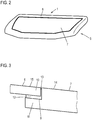
- Fig. 2 shows the fully assembled body component 1, i.e. the front flap, in this view, since it is a relatively flat component, ultimately only the outer component 5 with the outer component frame 6 and the photovoltaic module 7 inserted into the opening 8 can be seen.
- the in Fig. 3 The enlarged partial view shown of the connection area of the outer frame 6 with the photovoltaic module 7 shows that the photovoltaic module, which consists for example of an upper and a lower safety glass pane or polymer pane or the like and a solar cell plane inserted between them, has a fold 9 running around the edge.
- the edge 10 of the outer part 6 engages, as Fig. 3 clearly shows. That is, the outer part edge 10 and the edge 11 of the photovoltaic module 7 overlap one another. This makes it possible, for example, to provide an adhesive connection 12 in this area, that is to say to firmly bond the two components to one another.
- an adhesive cord can be placed on or in the fold 9, which is pressed when the photovoltaic module 7 and the outer subframe 6 are pressed together and, on the one hand, realizes the fixed adhesive connection, but also on the other a minimal circumferential gap 13 resulting between the photovoltaic module 7 and the outer partial frame 6 seals.
- the depth of the fold 9 is dimensioned such that the outer surface 14 of the photovoltaic module 7 and the outer surface 15 of the outer frame component 6 merge flush so that there is no edge or step in this area.
- the rebate depth is of course designed taking into account the thickness of the resulting adhesive connection 12.
- the body component according to the invention offers a number of advantages. On the one hand, it enables the simple integration of one or more photovoltaic modules into a body component and thus on the motor vehicle, specifically within the scope of the usual assembly line, which means that the assembly can be easily integrated into the existing assembly process. All that is required is a corresponding tool design for forming the opening 8 on the outer frame part 6 and, if necessary, a further adhesive device. Because body components of this type can consequently be equipped with a photovoltaic module in a simple manner, it is possible to install them in a more or less standardized manner in vehicles with partially or fully electric drives. Since the photovoltaic module 7 furthermore forms a central part of the outer part 5 and is accordingly stable and stiff, any requirements for pedestrian protection or other mechanical requirements can easily be met.
- the body component can of course also be, for example, a tailgate or a door or a roof component or the like.
Landscapes
- Engineering & Computer Science (AREA)
- Mechanical Engineering (AREA)
- Transportation (AREA)
- Chemical & Material Sciences (AREA)
- Combustion & Propulsion (AREA)
- Power Engineering (AREA)
- Body Structure For Vehicles (AREA)
Description
- Die Erfindung betrifft ein Karosseriebauteil für ein Kraftfahrzeug, umfassend ein Innenteil sowie ein mit den Innenteil verbundenes Außenteil, das in der Montagestellung eine Außenfläche des Kraftfahrzeugs bildet.
- Zunehmend werden Kraftfahrzeuge mit elektrischen Antrieben versehen, die naturgemäß immer wieder zu laden sind. Eine Möglichkeit hierzu besteht darin, das Fahrzeug außenseitig mit Solarzellen zu bestücken, die bei Lichteinfall einen Strom erzeugen, der zum Laden des Energiespeichers verwendet werden kann. Hierbei ist es bekannt, die Außenfläche des Kraftfahrzeugs, also die Karosserie respektive die entsprechenden, diese bildenden Karosseriebauteile zum Teil unmittelbar mit den Solarzellen zu bekleben und mit einer Schutzfolie abzudecken. Dies ist jedoch insoweit nachteilig, als dieses Bekleben relativ komplizier und aufwändig ist, da die Verklebung äußerst exakt erfolgen muss, was bei den gegebenen Außenflächengeometrien nicht ohne Weiteres möglich ist. Darüber hinaus lässt sich auch nur ein bedingter Schutz der Solarzellen gegen äußere Einflüsse, insbesondere Krafteinflüsse erreichen.
- Alternativ ist es bekannt, ein Glasschiebedach mit Solarzellen zu bestücken. Bei dem Glasschiebedach handelt es sich um ein Bauteil aus Sicherheitsglas, was es ermöglicht, bei einem mehrschichtigen Aufbau in einer Zwischenebene eine Solarzellenebene einzubringen, die dann ober- und unterseitig über entsprechende Glasebenen eingefasst und geschützt ist. Es handelt sich bei diesem Solarschiebedach jedoch um ein Spezialbauteil, das, nachdem es auch noch beweglich ist, in seinem Aufbau und seiner Konstruktion komplex ist. Darüber hinaus ist ein solches Solarschiebedach nur wenig verbreitet, da es keine Standardausstattung bei modernen Kraftfahrzeugen ist.
- Die
WO 2010/017847 A1 offenbart ein Karosseriebauteil gemäß dem Oberbegriff des Anspruchs 1. - Der Erfindung liegt damit das Problem zugrunde, eine Möglichkeit für eine verbesserte Integration eines Photovoltaikmoduls in ein Kraftfahrzeug anzugeben.
- Zur Lösung dieses Problems ist erfindungsgemäß ein Karosseriebauteil für ein Kraftfahrzeug vorgesehen, umfassend ein Innenteil sowie ein mit dem Innenteil verbundenes Außenteil, das in der Montagestellung eine Außenfläche des Kraftfahrzeugs bildet, wobei sich dieses Karosseriebauteil dadurch auszeichnet, dass das Außenteil einen Außenteilrahmen mit wenigstens einer großflächigen Öffnung und ein in diese eingesetztes, sie ausfüllendes und fest mit dem Außenteilrahmen verbundenes Photovoltaikmodul aufweist.
- Die Erfindung schlägt vor, das Photovoltaikmodul als unmittelbares Element eines Karosseriebauteils einzusetzen bzw. im Karosseriebauteil fest zu verbauen. Ein solchen Karosseriebauteil besteht üblicherweise aus einem Innenteil, das die wesentliche Tragfunktion übernimmt und beispielsweise rahmen- oder gitterartig ausgeführt ist. Vorgesehen ist des Weiteren ein Außenteil, das die eigentliche Außenfläche des Karosseriebauteils bildet und das fest mit dem Innenteil verbunden ist. Zwischen Innen- und Außenteil können gegebenenfalls weitere Verstärkungsteile montiert werden. Erfindungsgemäß wird nun das Außenteil zumindest zweiteilig ausgeführt, bestehend aus einem Außenteilrahmen und dem Photovoltaikmodul. Der Außenteilrahmen weist wenigstens eine möglichst großflächige Ausnehmung oder Öffnung auf, wobei über die Fläche des Außenteilrahmens auch mehrere Öffnungen ausgebildet sein können. In diese oder jede Öffnung wird erfindungsgemäß ein vorgefertigtes Photovoltaikmodul eingesetzt, das die Öffnung vollständig ausfüllt und das fest mit dem Außenteilrahmen verbunden ist. Das Photovoltaikmodul bildet daher zusammen mit dem Außenteilrahmen das Außenteil und die Außenfläche des Karosseriebauteils. Es ist fest integriert Bestandteil des Karosseriebauteils und eines der zentralen Elemente. Auf diese Weise ist eine einfache Integration eines Photovoltaikmoduls - von denen wie beschrieben an dem Karosseriebauteil auch mehrere vorgesehen werden können, wenn mehrere Öffnungen ausgebildet werden - möglich. Da das Karosseriebauteil ein zwingend vorzusehendes Bauteil für die Fahrzeugkarosse ist, ist eine einfache Integration des Photovoltaikmoduls am Fahrzeug möglich und damit die Ausrüstung quasi standardisiert möglich. Dies insbesondere, als die Montage des Photovoltaikmoduls im Karosseriebauteil ohne weiteres in den üblichen Produktions- bzw. Zusammenbauablauf integriert werden kann. Denn es ist lediglich erforderlich, einerseits bei der Herstellung des üblicherweise aus einem Blechbauteil gefertigten Außenteils zur Bildung des Außenteilrahmens in einem entsprechenden Stanzvorgang die eine oder die mehreren Öffnungen auszubilden, was ohne weiteres im Rahmen des eigentlichen Umformvorgangs, in dem eine Blechtafel der Form und Geometrie des gewünschten Außenteils entsprechend umgeformt wird, erfolgen kann. Dieser Außenteilrahmen wird sodann in der Montagestrecke an die entsprechende Montagestelle zugeführt, zusammen mit dem Innenteil, etwaigen Verstärkungsteilen und dem bevorzugt ebenfalls vorgefertigten Photovoltaikmodul, das nun an der Montagestation innerhalb des Montagebands mit dem Außenteilrahmen verbunden wird und demzufolge das fertige Außenteil konfiguriert wird. Das heißt, dass die Integration des Photovoltaikmoduls ohne weiteres in den üblichen Zusammenbauvorgang integriert werden kann. Selbst eine Montage des Photovoltaikmoduls aus vorgefertigten bzw. vorkonfigurierten Teilen am Band vor dessen Integration am Außenteilrahmen ist denkbar.
- Das Photovoltaikmodul bildet wie beschrieben einen festen Bestandteil des Außenteils und damit einen festen, tragenden Bestandteil des Karosseriebauteils. Aus diesem Grund kann es entsprechend stabil dimensioniert werden, beispielsweise bestehend aus einer Solarzellenebene, die zwischen entsprechend stabilen Trägerebenen eingebunden ist, so dass einerseits die Solarzellen vollständig geschützt sind, andererseits aber auch eine extreme Stabilität des Photovoltaikmoduls, ähnlich wie bei einem Glasschiebedach, gegeben ist.
- Die feste Verbindung des Photovoltaikmoduls mit dem Außenteilrahmen erfolgt bevorzugt über eine Klebeverbindung. Diese kann automatisiert erzeugt werden, indem mit einem Roboter automatisch eine Klebeschnur im Verbindungsbereich auf den Außenteilrahmen und/oder das Photovoltaikmodul gelegt wird, wonach die beiden Bauteile zusammengefügt und verklebt werden. Alternativ dazu ist es auch denkbar, beide unter Verwendung geeigneter Befestigungselemente aneinander zu fixieren, beispielsweise zu verschrauben, was mitunter ebenfalls automatisiert erfolgen kann.
- Um den Außenteilrahmen und das Photovoltaikmodul auf einfache Weise aneinander befestigen zu können, sieht eine zweckmäßige Weiterbildung der Erfindung vor, dass beide randseitig formschlüssig ineinander greifen. Es ergibt sich also ein randseitiger Formschluss respektive Überlapp, im Bereich dessen auf einfache Weise die Teileverbindung erfolgen kann. Bevorzugt weist hierzu das Photovoltaikmodul einen randseitig umlaufenden, zur Außenfläche hin offenen Falz auf, in den der die Öffnung begrenzende Außenteilrahmenrand eingreift. Im Randbereich überlappen beide also und liegen flächig aneinander, wobei in diesem Überlappbereich beispielsweise die Klebeverbindung vorgesehen werden kann.
- Eine zweckmäßige Weiterbildung der Erfindung sieht vor, dass die Außenfläche des Außenrahmenteils und die Außenfläche des Photovoltaikmoduls bündig ineinander übergehen. Die Öffnung ist in ihrer Größe und Geometrie so bemessen, dass sie so exakt wie möglich der Größe und Geometrie des Photovoltaikmoduls entspricht. Darüber hinaus ist die Befestigung der beiden Bauteile aneinander so gewählt, dass die Außenflächen bündig ineinander übergehen, so dass sich keine Kante oder Stufe im Übergangsbereich an der Außenfläche ergibt. Dadurch, dass die Öffnung und das Photovoltaikmodul einander großen- und geometriemäßig entsprechen, ergibt sich auch nur ein minimaler umlaufender Spalt, der beispielsweise mit dem Klebemittel im Rahmen der Montage bereits abgedichtet werden kann, alternativ kann in diesem Bereich bei Bedarf ein zusätzliches fluides, aushärtendes Dichtmittel eingebracht werden.
- Bei dem Karosseriebauteil kann es sich beispielsweise um eine Front- oder Heckklappe handeln. Denkbar ist auch die Ausführung als Tür oder als Dachbauteil, mithin also als großflächige Karosserieteile, die die Integration eines entsprechenden großflächigen Photovoltaikmoduls ermöglichen. Denkbar ist aber auch die Ausführung als Kotflügel oder als Spoiler, wobei diese Aufzählung nicht abschließend ist.
- Neben dem Karosseriebauteil betrifft die Erfindung ferner ein Kraftfahrzeug, umfassend wenigstens ein derartiges Karosseriebauteil.
- Weitere Vorteile und Einzelheiten der vorliegenden Erfindung ergeben sich aus den im Folgenden beschriebenen Ausführungsbeispielen sowie anhand der Zeichnungen. Dabei zeigen:
- Fig. 1
- eine Prinzipdarstellung als Explosionsansicht eines erfindungsgemäßen Karosseriebauteils,
- Fig. 2
- das Karosseriebauteil aus
Fig. 1 in montierter Form, und - Fig. 3
- eine vergrößerte Teilansicht des Karosseriebauteils aus
Fig. 2 . -
Fig. 1 zeigt in einer Explosionsdarstellung ein erfindungsgemäßes Karosseriebauteil 1 in Form einer Frontklappe eines Kraftfahrzeugs, also einer Motorhaube. Das Karosseriebauteil 1 besteht aus einem Innenteil 2, das im Vorliegenden eine Art Gitterstruktur aufweist, und an dem im gezeigten Beispiel bereits beidseitig Scharniere 3 zur Schwenkbefestigung an der Karosserie vorgesehen sind. Bei dem Innenteil 2 handelt es sich üblicherweise um ein Metallbauteil, üblicherweise aus Aluminium, jedoch kann es auch aus anderen Materialien, insbesondere Kompositmaterialien oder dergleichen bestehen. - Vorgesehen sind des Weiteren diverse Verstärkungsteile 4, die im Inneren des montierten Karosseriebauteils 1 aufgenommen sind und der spezifischen Aussteifung oder Verstärkung desselben dienen.
- Gezeigt ist des Weiteren ein Außenteil 5, bestehend aus zwei separaten Bauteilen, nämlich einem Außenteilrahmen 6, ebenfalls bevorzugt ein Metall- bzw. Aluminiumbauteil oder ein Komposit- oder Kunststoffbauteil oder dergleichen, sowie einem Photovoltaikmodul 7. Das Außenrahmenteil 6 weist im gezeigten Beispiel eine großflächige Öffnung 8, also einen entsprechenden Ausschnitt auf, so dass lediglich noch eine umlaufende, schmale Rahmenstruktur verbleibt. In diese Öffnung wird, worauf Nachfolgend noch eingegangen wird, das Photovoltaikmodul 7 eingesetzt. Die Größe und Form respektive Geometrie der Öffnung 8 und die Größe bzw. Geometrie des Photovoltaikmoduls 7 sind so aufeinander abgestimmt, dass das Photovoltaikmodul 7 mit möglichst minimalem Spalt in das Außenrahmenteil 6 respektive die Öffnung 8 eingesetzt werden kann.
- Die Montage des Karosseriebauteils 1 kann unmittelbar am Band erfolgen, das heißt, dass an die Montageposition einerseits das Innenteil sowie die Verstärkungsteile und gegebenenfalls weitere, nicht näher gezeigte Elemente geliefert werden, andererseits aber auch das Photovoltaikmodul 7 und der Außenteilrahmen 8, die dann vor Ort am Band miteinander verbunden werden, wonach das gefertigte Außenteil 5 mit den anderen Komponenten (Innenteil 2, Verstärkungsteile 4 etc.) verbunden werden.
-
Fig. 2 zeigt das fertig montierte Karosseriebauteil 1, also die Frontklappe, wobei in dieser Ansicht, da es sich um ein relativ flaches Bauteil handelt, letztlich nur das Außenbauteil 5 mit dem Außenbauteilrahmen 6 und dem in die Öffnung 8 eingesetzten Photovoltaikmodul 7 zu sehen ist. - Der in
Fig. 3 gezeigten vergrößerten Teilansicht des Verbindungsbereichs des Außenteilrahmens 6 mit dem Photovoltaikmodul 7 ist zu entnehmen, dass das Photovoltaikmodul, das beispielsweise aus einer oberen und einer unteren Sicherheitsglasscheibe oder Polymerscheibe oder Ähnlichem und einer dazwischen eingelegten Solarzellenebene besteht, einen randseitig umlaufenden Falz 9 aufweist. In diesen Falz 9 greift der Rand 10 des Außenteils 6 ein, wieFig. 3 anschaulich zeigt. Das heißt, dass der Außenteilrand 10 und der Rand 11 des Photovoltaikmoduls 7 miteinander überlappen. Dies ermöglicht es, in diesem Bereich beispielsweise eine Klebeverbindung 12 vorzusehen, mithin also die beiden Bauteile fest miteinander zu verkleben. Hierzu kann im Rahmen des Fügens des Photovoltaikmoduls 7 mit dem Außenteilrahmen 6 mittels eines Roboters eine Klebemittelschnur auf bzw. in den Falz 9 gelegt werden, die beim Zusammendrücken des Photovoltaikmoduls 7 und des Außenteilrahmens 6 verdrückt wird und einerseits die feste Klebeverbindung realisiert, andererseits aber auch einen sich zwischen dem Photovoltaikmodul 7 und dem Außenteilrahmen 6 ergebenden, minimalen umlaufenden Spalt 13 abdichtet. - Wie
Fig. 3 ferner zeigt, ist die Tiefe des Falzes 9 so bemessen, dass die Außenfläche 14 des Photovoltaikmoduls 7 und die Außenfläche 15 des Außenrahmenbauteils 6 bündig ineinander übergehen, so dass sich in diesem Bereich also keine Kante oder Stufe ergibt. Die Auslegung der Falztiefe erfolgt dabei natürlich unter Berücksichtigung der Dicke der sich ergebenden Klebeverbindung 12. - Das erfindungsgemäße Karosseriebauteil bietet eine Reihe von Vorteilen. Zum einen ermöglicht es die einfache Integration eines oder mehrerer Photovoltaikmodule in ein Karosseriebauteil und damit am Kraftfahrzeug, und zwar im Rahmen der üblichen Bandmontage, das heißt, dass die Montage in den bestehenden Zusammenbauablauf ohne weiteres integriert werden kann. Erforderlich ist lediglich eine entsprechende Werkzeugausgestaltung zur Ausbildung der Öffnung 8 am Außenrahmenteil 6 und gegebenenfalls eine weitere Klebevorrichtung. Dadurch, dass demzufolge auf einfache Weise derartige Karosseriebauteile mit einem Photovoltaikmodul ausgerüstet werden können, ist es möglich, diese auch quasi standardisiert bei Fahrzeugen mit teil- oder vollelektrischem Antrieb zu verbauen. Da das Photovoltaikmodul 7 des Weiteren einen zentralen Teil des Außenteils 5 bildet und demzufolge entsprechend stabil und steif ist, können hiermit auch ohne weiteres etwaige Anforderungen an einen Fußgängerschutz oder sonstige mechanische Anforderungen erfüllt werden.
- Abschließend der Hinweis, dass die Erfindung nicht auf das gezeigte Ausführungsbeispiel einer Frontklappe beschränkt ist. Bei dem Karosseriebauteil kann es sich selbstverständlich auch beispielsweise um eine Heckklappe oder um eine Tür oder ein Dachbauteil oder dergleichen handeln.
Claims (7)
- Karosseriebauteil für ein Kraftfahrzeug, umfassend ein Innenteil (2) sowie ein mit dem Innenteil verbundenes Außenteil (5), das in der Montagestellung eine Außenfläche des Kraftfahrzeugs bildet,dadurch gekennzeichnet,dass das Außenteil (5) einen Außenteilrahmen (6) mit wenigstens einer großflächigen Öffnung (8) und ein in diese eingesetztes, sie ausfüllendes und fest mit dem Außenteilrahmen (6) verbundenes Photovoltaikmodul (7) aufweist.
- Karosseriebauteil nach Anspruch 1,dadurch gekennzeichnet,dass das Photovoltaikmodul (7) über eine Klebeverbindung (12) oder über Befestigungselemente mit dem Außenteilrahmen (6) verbunden ist.
- Karosseriebauteil nach Anspruch 1 oder 2,dadurch gekennzeichnet,dass das der Außenteilrahmen (6) und das Photovoltaikmodul (7) randseitig formschlüssig ineinander greifen.
- Karosseriebauteil nach Anspruch 3,dadurch gekennzeichnet,dass am Photovoltaikmodul (7) ein randseitig umlaufender, zur Außenfläche hin offener Falz (9) vorgesehen ist, in den der Außenteilrahmenrand (10) eingreift.
- Karosseriebauteil nach einem der vorangehenden Ansprüche,dadurch gekennzeichnet,dass die Außenfläche (15) des Außenrahmenteils (6) und die Außenfläche (14) des Photovoltaikmoduls (7) bündig ineinander übergehen.
- Karosseriebauteil nach einem der vorangehenden Ansprüche,dadurch gekennzeichnet,dass es eine Front- oder Heckklappe, eine Tür, ein Dachbauteil, ein Kotflügel oder ein Spoiler ist.
- Kraftfahrzeug, umfassend wenigstens ein Karosseriebauteil (1) nach einem der vorangehenden Ansprüche.
Applications Claiming Priority (1)
| Application Number | Priority Date | Filing Date | Title |
|---|---|---|---|
| DE102018216817.2A DE102018216817A1 (de) | 2018-09-28 | 2018-09-28 | Karosseriebauteil für ein Kraftfahrzeug |
Publications (2)
| Publication Number | Publication Date |
|---|---|
| EP3628573A1 EP3628573A1 (de) | 2020-04-01 |
| EP3628573B1 true EP3628573B1 (de) | 2021-09-22 |
Family
ID=68072188
Family Applications (1)
| Application Number | Title | Priority Date | Filing Date |
|---|---|---|---|
| EP19199965.5A Active EP3628573B1 (de) | 2018-09-28 | 2019-09-26 | Karosseriebauteil für ein kraftfahrzeug |
Country Status (2)
| Country | Link |
|---|---|
| EP (1) | EP3628573B1 (de) |
| DE (1) | DE102018216817A1 (de) |
Families Citing this family (2)
| Publication number | Priority date | Publication date | Assignee | Title |
|---|---|---|---|---|
| JP7593381B2 (ja) * | 2022-09-06 | 2024-12-03 | トヨタ自動車株式会社 | 車両 |
| CN117261779B (zh) * | 2023-09-28 | 2025-09-23 | 安徽合力股份有限公司 | 一种工业车辆机舱密封结构 |
Family Cites Families (7)
| Publication number | Priority date | Publication date | Assignee | Title |
|---|---|---|---|---|
| DE3835560A1 (de) * | 1988-10-19 | 1990-04-26 | Kaaden Hans Heinrich | Dach aus kunststoff fuer kraftfahrzeuge |
| US20110226312A1 (en) * | 2008-08-12 | 2011-09-22 | Webasto Ag | Vehicle surface component having a solar cell arrangement |
| KR101108996B1 (ko) * | 2009-04-28 | 2012-01-31 | 주식회사 이건창호 | 염료감응형 태양전지가 결합된 리어 스포일러 |
| FR2971479B1 (fr) * | 2011-02-10 | 2014-10-24 | Renault Sa | Dispositif support de panneau solaire photovoltaique pour vehicule automobile |
| CN203951400U (zh) * | 2014-06-30 | 2014-11-19 | 珠海新康杰特种车辆有限公司 | 救护车太阳能供电装置 |
| CN206579709U (zh) * | 2017-03-24 | 2017-10-24 | 北京铂阳顶荣光伏科技有限公司 | 车顶太阳能薄膜组件及太阳能汽车 |
| ES2899362T3 (es) * | 2017-07-26 | 2022-03-11 | Sono Motors Gmbh | Parte de carrocería y procedimiento para fabricar una parte de carrocería |
-
2018
- 2018-09-28 DE DE102018216817.2A patent/DE102018216817A1/de not_active Withdrawn
-
2019
- 2019-09-26 EP EP19199965.5A patent/EP3628573B1/de active Active
Also Published As
| Publication number | Publication date |
|---|---|
| DE102018216817A1 (de) | 2020-04-02 |
| EP3628573A1 (de) | 2020-04-01 |
Similar Documents
| Publication | Publication Date | Title |
|---|---|---|
| EP3532365B1 (de) | Karosserieteil und verfahren zum herstellen eines karosserieteils | |
| DE10163709B4 (de) | Modulartiges Fahrzeugdach | |
| EP2459432B1 (de) | Baukastensystem und verfahren zum herstellen eines dachmoduls | |
| EP3312033B1 (de) | Fahrzeugtür | |
| EP2020323A1 (de) | Fahrzeugdach mit einem Dachmodul | |
| DE102019128241A1 (de) | Türmodul mit rahmenloser glaskonfiguration mit einstellbaren glaslaufkanälen | |
| EP3221168B1 (de) | Rahmen eines fahrzeugdachs und dessen herstellung | |
| EP1651458B1 (de) | Kraftfahrzeugtür | |
| EP1494882B1 (de) | Fahrzeugtür und verfahren zu deren herstellung | |
| DE102012208670A1 (de) | Fahrzeugtür | |
| EP0684157B1 (de) | Mehrwandige Fahrzeugtür | |
| EP3628573B1 (de) | Karosseriebauteil für ein kraftfahrzeug | |
| DE102010031774A1 (de) | Anordnung eines Dachmoduls an einer Karosserie eines Kraftwagens | |
| DE19727010B4 (de) | Fensterrahmenmodul zur Herstellung von Kraftfahrzeugtüren | |
| DE10334143B4 (de) | Kraftfahrzeugtür | |
| DE602004003082T2 (de) | Verfahren zum Zusammenbauen von Kraftfahrzeugkarosserie mit Türen, gemäß des Verfahrens hergstellten Kraftfahrzeugkarosserie und Türen für solche Kraftfahrzeugkarosserie | |
| EP2492123A1 (de) | Fensterelement für eine Seitentür, insbesondere eine hintere Seitentür, eines Kraftwagens | |
| DE112020001731T5 (de) | Sekundärdichtung an einem träger für ein türmodul | |
| WO2020035280A1 (de) | Dachmodul für ein fahrzeugdach eines personenkraftwagens | |
| DE102016002574A1 (de) | Kraftfahrzeugkarosserie | |
| EP1669277A1 (de) | Karosserieanbauteil, Zwischenprodukt und Verfahren zum Herstellen eines solchen Karosserieanbauteils | |
| EP1567406B1 (de) | Verfahren zur montage und bearbeitung eines anbauteils sowie adapter | |
| DE10319783A1 (de) | Fahrzeugdach mit einer Dachöffnung | |
| DE10328092B4 (de) | Fahrzeugdach mit einem auf eine feste Dachstruktur aufgesetzten Dachteil | |
| EP2072733B1 (de) | Seitenverkleidung für ein Fahrzeug |
Legal Events
| Date | Code | Title | Description |
|---|---|---|---|
| PUAI | Public reference made under article 153(3) epc to a published international application that has entered the european phase |
Free format text: ORIGINAL CODE: 0009012 |
|
| STAA | Information on the status of an ep patent application or granted ep patent |
Free format text: STATUS: THE APPLICATION HAS BEEN PUBLISHED |
|
| AK | Designated contracting states |
Kind code of ref document: A1 Designated state(s): AL AT BE BG CH CY CZ DE DK EE ES FI FR GB GR HR HU IE IS IT LI LT LU LV MC MK MT NL NO PL PT RO RS SE SI SK SM TR |
|
| AX | Request for extension of the european patent |
Extension state: BA ME |
|
| STAA | Information on the status of an ep patent application or granted ep patent |
Free format text: STATUS: REQUEST FOR EXAMINATION WAS MADE |
|
| 17P | Request for examination filed |
Effective date: 20201001 |
|
| RBV | Designated contracting states (corrected) |
Designated state(s): AL AT BE BG CH CY CZ DE DK EE ES FI FR GB GR HR HU IE IS IT LI LT LU LV MC MK MT NL NO PL PT RO RS SE SI SK SM TR |
|
| REG | Reference to a national code |
Ref country code: DE Ref legal event code: R079 Ref document number: 502019002333 Country of ref document: DE Free format text: PREVIOUS MAIN CLASS: B62D0025100000 Ipc: B60J0005040000 |
|
| GRAP | Despatch of communication of intention to grant a patent |
Free format text: ORIGINAL CODE: EPIDOSNIGR1 |
|
| STAA | Information on the status of an ep patent application or granted ep patent |
Free format text: STATUS: GRANT OF PATENT IS INTENDED |
|
| RIC1 | Information provided on ipc code assigned before grant |
Ipc: B62D 35/00 20060101ALI20210623BHEP Ipc: B62D 27/02 20060101ALI20210623BHEP Ipc: B62D 25/06 20060101ALI20210623BHEP Ipc: B60L 8/00 20060101ALI20210623BHEP Ipc: B62D 25/10 20060101ALI20210623BHEP Ipc: B60J 5/00 20060101ALI20210623BHEP Ipc: B60J 5/04 20060101AFI20210623BHEP |
|
| INTG | Intention to grant announced |
Effective date: 20210706 |
|
| GRAS | Grant fee paid |
Free format text: ORIGINAL CODE: EPIDOSNIGR3 |
|
| GRAA | (expected) grant |
Free format text: ORIGINAL CODE: 0009210 |
|
| STAA | Information on the status of an ep patent application or granted ep patent |
Free format text: STATUS: THE PATENT HAS BEEN GRANTED |
|
| AK | Designated contracting states |
Kind code of ref document: B1 Designated state(s): AL AT BE BG CH CY CZ DE DK EE ES FI FR GB GR HR HU IE IS IT LI LT LU LV MC MK MT NL NO PL PT RO RS SE SI SK SM TR |
|
| REG | Reference to a national code |
Ref country code: GB Ref legal event code: FG4D Free format text: NOT ENGLISH |
|
| REG | Reference to a national code |
Ref country code: DE Ref legal event code: R096 Ref document number: 502019002333 Country of ref document: DE |
|
| REG | Reference to a national code |
Ref country code: IE Ref legal event code: FG4D Free format text: LANGUAGE OF EP DOCUMENT: GERMAN |
|
| REG | Reference to a national code |
Ref country code: CH Ref legal event code: EP Ref country code: AT Ref legal event code: REF Ref document number: 1432049 Country of ref document: AT Kind code of ref document: T Effective date: 20211015 |
|
| REG | Reference to a national code |
Ref country code: LT Ref legal event code: MG9D |
|
| REG | Reference to a national code |
Ref country code: NL Ref legal event code: MP Effective date: 20210922 |
|
| PG25 | Lapsed in a contracting state [announced via postgrant information from national office to epo] |
Ref country code: FI Free format text: LAPSE BECAUSE OF FAILURE TO SUBMIT A TRANSLATION OF THE DESCRIPTION OR TO PAY THE FEE WITHIN THE PRESCRIBED TIME-LIMIT Effective date: 20210922 Ref country code: RS Free format text: LAPSE BECAUSE OF FAILURE TO SUBMIT A TRANSLATION OF THE DESCRIPTION OR TO PAY THE FEE WITHIN THE PRESCRIBED TIME-LIMIT Effective date: 20210922 Ref country code: SE Free format text: LAPSE BECAUSE OF FAILURE TO SUBMIT A TRANSLATION OF THE DESCRIPTION OR TO PAY THE FEE WITHIN THE PRESCRIBED TIME-LIMIT Effective date: 20210922 Ref country code: LT Free format text: LAPSE BECAUSE OF FAILURE TO SUBMIT A TRANSLATION OF THE DESCRIPTION OR TO PAY THE FEE WITHIN THE PRESCRIBED TIME-LIMIT Effective date: 20210922 Ref country code: BG Free format text: LAPSE BECAUSE OF FAILURE TO SUBMIT A TRANSLATION OF THE DESCRIPTION OR TO PAY THE FEE WITHIN THE PRESCRIBED TIME-LIMIT Effective date: 20211222 Ref country code: HR Free format text: LAPSE BECAUSE OF FAILURE TO SUBMIT A TRANSLATION OF THE DESCRIPTION OR TO PAY THE FEE WITHIN THE PRESCRIBED TIME-LIMIT Effective date: 20210922 Ref country code: NO Free format text: LAPSE BECAUSE OF FAILURE TO SUBMIT A TRANSLATION OF THE DESCRIPTION OR TO PAY THE FEE WITHIN THE PRESCRIBED TIME-LIMIT Effective date: 20211222 |
|
| PG25 | Lapsed in a contracting state [announced via postgrant information from national office to epo] |
Ref country code: LV Free format text: LAPSE BECAUSE OF FAILURE TO SUBMIT A TRANSLATION OF THE DESCRIPTION OR TO PAY THE FEE WITHIN THE PRESCRIBED TIME-LIMIT Effective date: 20210922 Ref country code: GR Free format text: LAPSE BECAUSE OF FAILURE TO SUBMIT A TRANSLATION OF THE DESCRIPTION OR TO PAY THE FEE WITHIN THE PRESCRIBED TIME-LIMIT Effective date: 20211223 |
|
| REG | Reference to a national code |
Ref country code: BE Ref legal event code: MM Effective date: 20210930 |
|
| PG25 | Lapsed in a contracting state [announced via postgrant information from national office to epo] |
Ref country code: IS Free format text: LAPSE BECAUSE OF FAILURE TO SUBMIT A TRANSLATION OF THE DESCRIPTION OR TO PAY THE FEE WITHIN THE PRESCRIBED TIME-LIMIT Effective date: 20220122 Ref country code: SK Free format text: LAPSE BECAUSE OF FAILURE TO SUBMIT A TRANSLATION OF THE DESCRIPTION OR TO PAY THE FEE WITHIN THE PRESCRIBED TIME-LIMIT Effective date: 20210922 Ref country code: RO Free format text: LAPSE BECAUSE OF FAILURE TO SUBMIT A TRANSLATION OF THE DESCRIPTION OR TO PAY THE FEE WITHIN THE PRESCRIBED TIME-LIMIT Effective date: 20210922 Ref country code: PT Free format text: LAPSE BECAUSE OF FAILURE TO SUBMIT A TRANSLATION OF THE DESCRIPTION OR TO PAY THE FEE WITHIN THE PRESCRIBED TIME-LIMIT Effective date: 20220124 Ref country code: PL Free format text: LAPSE BECAUSE OF FAILURE TO SUBMIT A TRANSLATION OF THE DESCRIPTION OR TO PAY THE FEE WITHIN THE PRESCRIBED TIME-LIMIT Effective date: 20210922 Ref country code: NL Free format text: LAPSE BECAUSE OF FAILURE TO SUBMIT A TRANSLATION OF THE DESCRIPTION OR TO PAY THE FEE WITHIN THE PRESCRIBED TIME-LIMIT Effective date: 20210922 Ref country code: ES Free format text: LAPSE BECAUSE OF FAILURE TO SUBMIT A TRANSLATION OF THE DESCRIPTION OR TO PAY THE FEE WITHIN THE PRESCRIBED TIME-LIMIT Effective date: 20210922 Ref country code: EE Free format text: LAPSE BECAUSE OF FAILURE TO SUBMIT A TRANSLATION OF THE DESCRIPTION OR TO PAY THE FEE WITHIN THE PRESCRIBED TIME-LIMIT Effective date: 20210922 Ref country code: CZ Free format text: LAPSE BECAUSE OF FAILURE TO SUBMIT A TRANSLATION OF THE DESCRIPTION OR TO PAY THE FEE WITHIN THE PRESCRIBED TIME-LIMIT Effective date: 20210922 Ref country code: AL Free format text: LAPSE BECAUSE OF FAILURE TO SUBMIT A TRANSLATION OF THE DESCRIPTION OR TO PAY THE FEE WITHIN THE PRESCRIBED TIME-LIMIT Effective date: 20210922 |
|
| REG | Reference to a national code |
Ref country code: DE Ref legal event code: R097 Ref document number: 502019002333 Country of ref document: DE |
|
| PG25 | Lapsed in a contracting state [announced via postgrant information from national office to epo] |
Ref country code: MC Free format text: LAPSE BECAUSE OF FAILURE TO SUBMIT A TRANSLATION OF THE DESCRIPTION OR TO PAY THE FEE WITHIN THE PRESCRIBED TIME-LIMIT Effective date: 20210922 |
|
| PG25 | Lapsed in a contracting state [announced via postgrant information from national office to epo] |
Ref country code: LU Free format text: LAPSE BECAUSE OF NON-PAYMENT OF DUE FEES Effective date: 20210926 Ref country code: IE Free format text: LAPSE BECAUSE OF NON-PAYMENT OF DUE FEES Effective date: 20210926 Ref country code: DK Free format text: LAPSE BECAUSE OF FAILURE TO SUBMIT A TRANSLATION OF THE DESCRIPTION OR TO PAY THE FEE WITHIN THE PRESCRIBED TIME-LIMIT Effective date: 20210922 Ref country code: BE Free format text: LAPSE BECAUSE OF NON-PAYMENT OF DUE FEES Effective date: 20210930 |
|
| PLBE | No opposition filed within time limit |
Free format text: ORIGINAL CODE: 0009261 |
|
| STAA | Information on the status of an ep patent application or granted ep patent |
Free format text: STATUS: NO OPPOSITION FILED WITHIN TIME LIMIT |
|
| 26N | No opposition filed |
Effective date: 20220623 |
|
| PG25 | Lapsed in a contracting state [announced via postgrant information from national office to epo] |
Ref country code: SI Free format text: LAPSE BECAUSE OF FAILURE TO SUBMIT A TRANSLATION OF THE DESCRIPTION OR TO PAY THE FEE WITHIN THE PRESCRIBED TIME-LIMIT Effective date: 20210922 |
|
| PG25 | Lapsed in a contracting state [announced via postgrant information from national office to epo] |
Ref country code: IT Free format text: LAPSE BECAUSE OF FAILURE TO SUBMIT A TRANSLATION OF THE DESCRIPTION OR TO PAY THE FEE WITHIN THE PRESCRIBED TIME-LIMIT Effective date: 20210922 |
|
| REG | Reference to a national code |
Ref country code: CH Ref legal event code: PL |
|
| PG25 | Lapsed in a contracting state [announced via postgrant information from national office to epo] |
Ref country code: CY Free format text: LAPSE BECAUSE OF FAILURE TO SUBMIT A TRANSLATION OF THE DESCRIPTION OR TO PAY THE FEE WITHIN THE PRESCRIBED TIME-LIMIT Effective date: 20210922 |
|
| P01 | Opt-out of the competence of the unified patent court (upc) registered |
Effective date: 20230530 |
|
| PG25 | Lapsed in a contracting state [announced via postgrant information from national office to epo] |
Ref country code: SM Free format text: LAPSE BECAUSE OF FAILURE TO SUBMIT A TRANSLATION OF THE DESCRIPTION OR TO PAY THE FEE WITHIN THE PRESCRIBED TIME-LIMIT Effective date: 20210922 Ref country code: LI Free format text: LAPSE BECAUSE OF NON-PAYMENT OF DUE FEES Effective date: 20220930 Ref country code: HU Free format text: LAPSE BECAUSE OF FAILURE TO SUBMIT A TRANSLATION OF THE DESCRIPTION OR TO PAY THE FEE WITHIN THE PRESCRIBED TIME-LIMIT; INVALID AB INITIO Effective date: 20190926 Ref country code: CH Free format text: LAPSE BECAUSE OF NON-PAYMENT OF DUE FEES Effective date: 20220930 |
|
| PG25 | Lapsed in a contracting state [announced via postgrant information from national office to epo] |
Ref country code: MK Free format text: LAPSE BECAUSE OF FAILURE TO SUBMIT A TRANSLATION OF THE DESCRIPTION OR TO PAY THE FEE WITHIN THE PRESCRIBED TIME-LIMIT Effective date: 20210922 |
|
| PG25 | Lapsed in a contracting state [announced via postgrant information from national office to epo] |
Ref country code: MT Free format text: LAPSE BECAUSE OF FAILURE TO SUBMIT A TRANSLATION OF THE DESCRIPTION OR TO PAY THE FEE WITHIN THE PRESCRIBED TIME-LIMIT Effective date: 20210922 |
|
| PGFP | Annual fee paid to national office [announced via postgrant information from national office to epo] |
Ref country code: DE Payment date: 20250930 Year of fee payment: 7 |
|
| PGFP | Annual fee paid to national office [announced via postgrant information from national office to epo] |
Ref country code: GB Payment date: 20250923 Year of fee payment: 7 |
|
| PGFP | Annual fee paid to national office [announced via postgrant information from national office to epo] |
Ref country code: FR Payment date: 20250924 Year of fee payment: 7 |
|
| REG | Reference to a national code |
Ref country code: AT Ref legal event code: MM01 Ref document number: 1432049 Country of ref document: AT Kind code of ref document: T Effective date: 20240926 |
|
| PG25 | Lapsed in a contracting state [announced via postgrant information from national office to epo] |
Ref country code: TR Free format text: LAPSE BECAUSE OF FAILURE TO SUBMIT A TRANSLATION OF THE DESCRIPTION OR TO PAY THE FEE WITHIN THE PRESCRIBED TIME-LIMIT Effective date: 20210922 |
|
| PG25 | Lapsed in a contracting state [announced via postgrant information from national office to epo] |
Ref country code: AT Free format text: LAPSE BECAUSE OF NON-PAYMENT OF DUE FEES Effective date: 20240926 |
|
| PGFP | Annual fee paid to national office [announced via postgrant information from national office to epo] |
Ref country code: AT Payment date: 20260410 Year of fee payment: 5 |