EP3628562B1 - Railway vehicle - Google Patents
Railway vehicle Download PDFInfo
- Publication number
- EP3628562B1 EP3628562B1 EP19196201.8A EP19196201A EP3628562B1 EP 3628562 B1 EP3628562 B1 EP 3628562B1 EP 19196201 A EP19196201 A EP 19196201A EP 3628562 B1 EP3628562 B1 EP 3628562B1
- Authority
- EP
- European Patent Office
- Prior art keywords
- deflector
- nose
- bogie
- railway vehicle
- train
- Prior art date
- Legal status (The legal status is an assumption and is not a legal conclusion. Google has not performed a legal analysis and makes no representation as to the accuracy of the status listed.)
- Active
Links
- 230000000694 effects Effects 0.000 description 2
- 238000005265 energy consumption Methods 0.000 description 2
- 230000010355 oscillation Effects 0.000 description 2
- 230000000052 comparative effect Effects 0.000 description 1
- 239000000470 constituent Substances 0.000 description 1
- 239000007788 liquid Substances 0.000 description 1
- 238000000034 method Methods 0.000 description 1
- 230000035939 shock Effects 0.000 description 1
Images


Classifications
-
- B—PERFORMING OPERATIONS; TRANSPORTING
- B61—RAILWAYS
- B61D—BODY DETAILS OR KINDS OF RAILWAY VEHICLES
- B61D17/00—Construction details of vehicle bodies
- B61D17/02—Construction details of vehicle bodies reducing air resistance by modifying contour ; Constructional features for fast vehicles sustaining sudden variations of atmospheric pressure, e.g. when crossing in tunnels
-
- B—PERFORMING OPERATIONS; TRANSPORTING
- B61—RAILWAYS
- B61D—BODY DETAILS OR KINDS OF RAILWAY VEHICLES
- B61D49/00—Other details
-
- B—PERFORMING OPERATIONS; TRANSPORTING
- B61—RAILWAYS
- B61F—RAIL VEHICLE SUSPENSIONS, e.g. UNDERFRAMES, BOGIES OR ARRANGEMENTS OF WHEEL AXLES; RAIL VEHICLES FOR USE ON TRACKS OF DIFFERENT WIDTH; PREVENTING DERAILING OF RAIL VEHICLES; WHEEL GUARDS, OBSTRUCTION REMOVERS OR THE LIKE FOR RAIL VEHICLES
- B61F19/00—Wheel guards; Bumpers; Obstruction removers or the like
- B61F19/04—Bumpers or like collision guards
-
- Y—GENERAL TAGGING OF NEW TECHNOLOGICAL DEVELOPMENTS; GENERAL TAGGING OF CROSS-SECTIONAL TECHNOLOGIES SPANNING OVER SEVERAL SECTIONS OF THE IPC; TECHNICAL SUBJECTS COVERED BY FORMER USPC CROSS-REFERENCE ART COLLECTIONS [XRACs] AND DIGESTS
- Y02—TECHNOLOGIES OR APPLICATIONS FOR MITIGATION OR ADAPTATION AGAINST CLIMATE CHANGE
- Y02T—CLIMATE CHANGE MITIGATION TECHNOLOGIES RELATED TO TRANSPORTATION
- Y02T30/00—Transportation of goods or passengers via railways, e.g. energy recovery or reducing air resistance
Definitions
- the present invention generally relates to a railway vehicle, especially a cover for the bottom of the nose of the railway vehicle.
- High-speed rail networks answer the need to quickly convey passengers and freight by means of a transportation system that minimizes the impact on the environment both in terms of energy consumption and noise generated.
- aerodynamic resistance to advancement also known as drag
- aerodynamic noise are proportional to, respectively, the second and the sixth power of speed. Accordingly, at high speed, the train aerodynamics account both for the largest amount of energy required to drive the train and for the largest contribution to noise. Therefore, an aerodynamically efficient and noise-wise unobtrusive train shape is sought after.
- the key technique to suppress the generation of drag (and, consequently, energy consumption), and noise is to streamline the train by preventing the airflow from running over the train areas that feature projecting parts (e.g. bogie parts, nose-underside parts) and/or cavities (e.g. the cavities accommodating the bogies).
- projecting parts e.g. bogie parts, nose-underside parts
- cavities e.g. the cavities accommodating the bogies.
- projecting parts generate vortices that increase noise
- large cavities cause the air to flow against the windward faces of the cavities, thus creating areas of high pressure pushing the cavities along with the flow, which, in turns, implies greater drag.
- the train leading-car bottom is the most critical train area in that the incoming flow is fastest because the boundary layer around the train is not fully developed, and it features many projecting parts (for example, antenna, air horn, air-horn piping, transponder, and deflector) and large cavities (for example, hollow inside the skirt, and bogie cavity).
- projecting parts for example, antenna, air horn, air-horn piping, transponder, and deflector
- large cavities for example, hollow inside the skirt, and bogie cavity
- a frequently adopted solution for streamlining the train leading-car bottom is to cover the whole bottom area from the train nose tip to the cavity accommodating the bogie. Nonetheless, the train design may require a deflector to be placed somewhere between the nose tip and the bogie cavity.
- the deflector is a thick plate that is attached to a piston fitted with a damper and hinged under the train nose. In case of collision with bulky foreign objects located on the rails, the deflector absorbs the shock through the damper. The deflector protrudes below the front of the train nose bottom and vibrates with small oscillations with respect to the train nose because the car-body vibrations are transmitted through the damper.
- the conventional solution of covering the whole bottom is not applicable because the cover would hinder the vibration of the deflector.
- WO 2011/120834 proposes a rail vehicle according to the pre-characterising portion of claim 1.
- a cover for the bottom of the nose of a train leading car is necessary to reduce drag by preventing high-speed flow from running against the projecting parts therein located, which are the parts installed below the nose bottom between the nose tip and the deflector, that is the parts making up the bottom equipment.
- such a cover is necessary to reduce noise by preventing high-speed inflow from running in the cavities therein located, that is to say the cavity accommodating the bottom equipment between the nose tip and the deflector and the cavity accommodating the bogie on the other side of the deflector.
- covers are adopted that cover the whole area of the leading-car bottom from its tip to the bogie cavity.
- some train configurations require the deflector to be clear of the cover to vibrate on the hinges it is mounted on through a piston, and conventional covers are not feasible because they would obstruct the deflector.
- a railway vehicle according to claim 1 is provided.
- the present invention allows such a railway vehicle to reduce drag and noise.
- a railway vehicle comprises a leading car.
- the leading car comprises a nose with a nose tip which is a tip of the leading car, a bogie, a bottom equipment of the nose which is the equipment that is fitted onto the bottom in a nose area, a skirt which is a strip enclosing the vertical sides of the bottom equipment, and a deflector which is a plate configured to deflect foreign objects on rail tracks and which is installed between the skirt and the bogie on a piston that is fitted with a damper and hinged to the nose underside.
- the railway vehicle (specifically, the leading car) comprises a nose-bottom cover which is different from conventional nose-bottom covers.
- the nose-bottom cover is composed of components including two components.
- the two components are a component spanning the whole bottom area from the leading-car tip to approximately the deflector front face (the face towards the leading-car tip) and a separate component located between the deflector back face (the face towards the bogie) and the bogie cavity.
- the former will be referred to as front component in the sequel, whereas the latter will be referred to as rear component.
- the front component prevents airflow (typically, high-speed flow) against the projecting parts located on the nose bottom between the deflector and the nose tip (typically, air horn, antenna, transponder, air-horn piping).
- airflow typically, high-speed flow
- the projecting parts located on the nose bottom between the deflector and the nose tip typically, air horn, antenna, transponder, air-horn piping.
- the front component has a ramp shape that deviates the airflow towards the rail away from the deflector.
- the rear component has a ramp shape that deviates airflow (typically, the high-speed flow) away towards the rail away from the nose bogie and its cavity.
- the rear component features a surface that faces the bogie.
- a surface spans the whole train width and runs from the rear component bottom to the train bottom between the deflector and the nose bogie in such a way as to prevent high-speed flow from under the bogie against the deflector.
- the embodiment it is possible to reduce noise by preventing high-speed flow against the projecting parts of the bottom equipment and deflector.
- the high-speed flow is deviated towards the rails by the front component.
- the deflector is able to vibrate unobstructed with respect to the train nose.
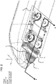
- FIG. 1 shows a view of the bottom of the leading car without the nose-bottom cover.
- the nose bogie (2) of the leading car comprises its constituent parts, that is to say the parallel beams (2.1) joining the wheel-bearing axles (2.2) and joined by the crossbeam (2.3).
- the bogie (2) supports the leading car and is placed on its bottom, that is to say on the leading-car side facing opposite to the y-direction.
- the bogie (2) lies in a cavity in the train bottom that is bounded along the z-axis in the positive direction by the deflector or some other bottom equipment and in the negative direction by other bottom equipment.
- the leading car is fitted with a deflector (3), which is a resilient structure that is mounted on a piston (4), which is fitted with a damper and hinged to the train bottom. Accordingly, the deflector (3) can vibrate both in the y- and z-directions with small oscillations.
- the nose of the leading car ahead of the bogie (2) in the z-direction is delimited by the nose front tip (1) and is fitted with bottom equipment (5) featuring projecting parts.
- a skirt (6) encloses the sides of the bottom equipment in the x- and z-directions but not in the negative y-direction.
- FIG. 2 shows a view of the bottom of the leading car with the nose-bottom cover.
- the nose-bottom cover is composed of at least two components including a front component (7) and a rear component (8).
- the front component (7) is located farther ahead of the deflector (3) in the z-direction and extends all over the bottom of the skirt (6).
- the rear component (8) is placed between the deflector (3) and the bogie (2). Both the components (7) and (8) leave the clearance that is required for the deflector (3) to vibrate.
- the front component (7) covers the bottom equipment inside the skirt (6), thus avoiding high-speed flow against it and reducing noise.
- FIG. 3 shows a view of the cross section A-A' of FIG. 2 .
- the cross section A-A' is any cross section that cuts the train and is parallel to the yz-plane.
- the front component (7), in the cross section A-A', is delineated by the front-component lower edge (10), that is to say the edge of the front component (7) that is closest to the top (9) of the rail.
- the front-component lower edge (10) has to vertices. Vertex V 1 is closer to the front tip (1) of the leading car, whereas vertex V 2 is closer to the deflector (3).
- the lower edge (10) bends towards the rail near V 2 , and the bend thus formed features a line L (tangent in V 2 ) that avoids (in other words, does not intercept) the deflector (3) in the cross section A-A'.
- the high-speed flow enters the cavity inside the skirt and hits the deflector (3) generating a highpressure area on the deflector front side, which, in turn, increases drag.
- FIG. 5 shows a relevant shape feature of the rear component (8) in the cross section A-A'.
- the rear component (8) in the cross section A-A', is delineated by an oblique edge (16), that is to say the edge of the rear component (8) that is closest to the top of the rail (9).
- the oblique edge (the lower edge) (16) has two vertices V 3 and V 4 . Vertex V 3 is closer to the deflector (3), whereas vertex V 4 is closer to the bogie (2). V 3 is higher above the top of the rail than V 4 in the y-direction.
- the height of the two vertices V 3 and V 4 above the top of the rail (9) is such that the high-speed flow that is deviated away from the deflector (3) by the front component (7) flows downstream and is deviated away from the bogie cavity by the rear component (8), thus reducing noise because high-speed flow does not run against the projecting parts of the bogie (2) and drag because it does not enter the bogie cavity.
- the height of V 3 and V 4 and the angle a that a line passing through V 3 and V 4 forms with the z-axis are supposed to be organized.
- V 3 and V 4 are approximately as high as the bottom of the deflector (3) in the y-direction, and the angle ⁇ (20) is around 30 degrees.
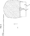
- FIG. 6 shows a view of the cross section B-B' of FIG. 3 .
- the cross section B-B' is parallel to the xy-plane, its view points in the z-direction, and cuts the train between the bogie (2) and the rear component (8).
- the rear component (8) is mounted below a support that fastens it to the train bottom.
- the back surface (21) of the support for the rear component (8) that is to say its surface facing the bogie (2), spans the whole train width and covers the area from the train bottom to the locus of the vertices V 4 for any cross sections A-A'. This surface prevents high-speed flow from running against the deflector (3) when the train is running in the opposite direction and the leading car becomes the trailing car.
- the support of the rear component (8) may enclose equipment such as the junction box and/or the cleaning-liquid tank.
Description
- The present invention generally relates to a railway vehicle, especially a cover for the bottom of the nose of the railway vehicle.
- High-speed rail networks answer the need to quickly convey passengers and freight by means of a transportation system that minimizes the impact on the environment both in terms of energy consumption and noise generated. At high speed, aerodynamic resistance to advancement, also known as drag, and aerodynamic noise are proportional to, respectively, the second and the sixth power of speed. Accordingly, at high speed, the train aerodynamics account both for the largest amount of energy required to drive the train and for the largest contribution to noise. Therefore, an aerodynamically efficient and noise-wise unobtrusive train shape is sought after.
- The key technique to suppress the generation of drag (and, consequently, energy consumption), and noise is to streamline the train by preventing the airflow from running over the train areas that feature projecting parts (e.g. bogie parts, nose-underside parts) and/or cavities (e.g. the cavities accommodating the bogies). The reason is that projecting parts generate vortices that increase noise, whereas large cavities cause the air to flow against the windward faces of the cavities, thus creating areas of high pressure pushing the cavities along with the flow, which, in turns, implies greater drag.
- The train leading-car bottom is the most critical train area in that the incoming flow is fastest because the boundary layer around the train is not fully developed, and it features many projecting parts (for example, antenna, air horn, air-horn piping, transponder, and deflector) and large cavities (for example, hollow inside the skirt, and bogie cavity).
- A frequently adopted solution for streamlining the train leading-car bottom is to cover the whole bottom area from the train nose tip to the cavity accommodating the bogie. Nonetheless, the train design may require a deflector to be placed somewhere between the nose tip and the bogie cavity. The deflector is a thick plate that is attached to a piston fitted with a damper and hinged under the train nose. In case of collision with bulky foreign objects located on the rails, the deflector absorbs the shock through the damper. The deflector protrudes below the front of the train nose bottom and vibrates with small oscillations with respect to the train nose because the car-body vibrations are transmitted through the damper. When the deflector is required, the conventional solution of covering the whole bottom is not applicable because the cover would hinder the vibration of the deflector.
- Usually trains travel back and forth in opposite directions, which means that the leading car becomes the trailing car and vice versa. The train shape should perform aerodynamically well, that is to say that high-speed flow against the bottom equipment and the deflector should be avoided, for both traveling directions. However, given that the flow speed under the train at the trailing car is significantly slower than at the leading car, the leading car is prominent in terms of drag and noise. From now on, unless otherwise specified, all the descriptions with respect to a train car will refer to the leading car.
-
WO 2011/120834 proposes a rail vehicle according to the pre-characterising portion ofclaim 1. - A cover for the bottom of the nose of a train leading car is necessary to reduce drag by preventing high-speed flow from running against the projecting parts therein located, which are the parts installed below the nose bottom between the nose tip and the deflector, that is the parts making up the bottom equipment.
- Furthermore, such a cover is necessary to reduce noise by preventing high-speed inflow from running in the cavities therein located, that is to say the cavity accommodating the bottom equipment between the nose tip and the deflector and the cavity accommodating the bogie on the other side of the deflector.
- Conventionally, covers are adopted that cover the whole area of the leading-car bottom from its tip to the bogie cavity. However, some train configurations require the deflector to be clear of the cover to vibrate on the hinges it is mounted on through a piston, and conventional covers are not feasible because they would obstruct the deflector.
- High-speed airflow must be deviated from the deflector irrespective of the traveling direction of the train. Otherwise, a significant amount of drag would be generated by the deflector.
- A railway vehicle according to
claim 1 is provided. - Even though a railway vehicle requires a deflector, the present invention allows such a railway vehicle to reduce drag and noise.
-
-
FIG. 1 shows a view of the bottom of the leading car without the nose-bottom cover. -
FIG. 2 shows a view of the bottom of the leading car with the nose-bottom cover which is composed of the front component and the rear component. -
FIG. 3 shows a view of the cross section A-A' inFIG. 2 . -
FIG. 4 shows a view of the cross section A-A' in accordance with a comparative example. -
FIG. 5 shows a view of the cross section A-A' inFIG. 2 . -
FIG. 6 shows a view of the cross section B-B' inFIG. 3 . - Here is summary of the following embodiment in accordance with example implementations.
- A railway vehicle comprises a leading car. The leading car comprises a nose with a nose tip which is a tip of the leading car, a bogie, a bottom equipment of the nose which is the equipment that is fitted onto the bottom in a nose area, a skirt which is a strip enclosing the vertical sides of the bottom equipment, and a deflector which is a plate configured to deflect foreign objects on rail tracks and which is installed between the skirt and the bogie on a piston that is fitted with a damper and hinged to the nose underside. The railway vehicle (specifically, the leading car) comprises a nose-bottom cover which is different from conventional nose-bottom covers. The nose-bottom cover is composed of components including two components. The two components are a component spanning the whole bottom area from the leading-car tip to approximately the deflector front face (the face towards the leading-car tip) and a separate component located between the deflector back face (the face towards the bogie) and the bogie cavity. The former will be referred to as front component in the sequel, whereas the latter will be referred to as rear component.
- The front component prevents airflow (typically, high-speed flow) against the projecting parts located on the nose bottom between the deflector and the nose tip (typically, air horn, antenna, transponder, air-horn piping).
- The front component has a ramp shape that deviates the airflow towards the rail away from the deflector.
- The rear component has a ramp shape that deviates airflow (typically, the high-speed flow) away towards the rail away from the nose bogie and its cavity.
- In order to reduce drag and noise when the train travels in the opposite direction and the leading car becomes the trailing car, the rear component features a surface that faces the bogie. Such a surface spans the whole train width and runs from the rear component bottom to the train bottom between the deflector and the nose bogie in such a way as to prevent high-speed flow from under the bogie against the deflector.
- According to the embodiment, it is possible to reduce drag through the front component by preventing the high-speed flow from entering the cavity accommodating the bottom equipment.
- According to the embodiment, it is possible to reduce noise by preventing high-speed flow against the projecting parts of the bottom equipment and deflector. The high-speed flow is deviated towards the rails by the front component.
- According to the embodiment, it is possible to reduce drag through the rear component by preventing the high-speed flow from entering the cavity accommodating the nose bogie.
- According to the embodiment, as opposed to conventional covers, the deflector is able to vibrate unobstructed with respect to the train nose.
- According to the embodiment, it is possible to prevent inflow against the bottom equipment also when the train is running in the opposite direction, that is to say when the leading car becomes the trailing car and vice versa, by employing a plate mounted between the rear component and the bogie.
- Here is the detailed description of the embodiment.
-
FIG. 1 shows a view of the bottom of the leading car without the nose-bottom cover. - The nose bogie (2) of the leading car comprises its constituent parts, that is to say the parallel beams (2.1) joining the wheel-bearing axles (2.2) and joined by the crossbeam (2.3). The bogie (2) supports the leading car and is placed on its bottom, that is to say on the leading-car side facing opposite to the y-direction. The bogie (2) lies in a cavity in the train bottom that is bounded along the z-axis in the positive direction by the deflector or some other bottom equipment and in the negative direction by other bottom equipment.
- As depicted in
FIG. 1 , the leading car is fitted with a deflector (3), which is a resilient structure that is mounted on a piston (4), which is fitted with a damper and hinged to the train bottom. Accordingly, the deflector (3) can vibrate both in the y- and z-directions with small oscillations. - As depicted in
Fig. 1 , the nose of the leading car ahead of the bogie (2) in the z-direction is delimited by the nose front tip (1) and is fitted with bottom equipment (5) featuring projecting parts. A skirt (6) encloses the sides of the bottom equipment in the x- and z-directions but not in the negative y-direction. -
FIG. 2 shows a view of the bottom of the leading car with the nose-bottom cover. - The nose-bottom cover is composed of at least two components including a front component (7) and a rear component (8). The front component (7) is located farther ahead of the deflector (3) in the z-direction and extends all over the bottom of the skirt (6). The rear component (8) is placed between the deflector (3) and the bogie (2). Both the components (7) and (8) leave the clearance that is required for the deflector (3) to vibrate. The front component (7) covers the bottom equipment inside the skirt (6), thus avoiding high-speed flow against it and reducing noise.
-
FIG. 3 shows a view of the cross section A-A' ofFIG. 2 . - The cross section A-A' is any cross section that cuts the train and is parallel to the yz-plane. The front component (7), in the cross section A-A', is delineated by the front-component lower edge (10), that is to say the edge of the front component (7) that is closest to the top (9) of the rail. The front-component lower edge (10) has to vertices. Vertex V1 is closer to the front tip (1) of the leading car, whereas vertex V2 is closer to the deflector (3). The lower edge (10) bends towards the rail near V2, and the bend thus formed features a line L (tangent in V2) that avoids (in other words, does not intercept) the deflector (3) in the cross section A-A'. In accordance with the flow direction (14) with the front component (7) depicted in
Fig. 3 , the bend of the lower edge (10) drives the high-speed flow in the tangent direction, which implies that the high-speed flow is driven downwards towards the top (9) of the rail and not against the deflector (3). Accordingly, the deflector (3) will not generate much noise. - In accordance with the flow direction (15) without the front component (7) depicted in
Fig. 4 , the high-speed flow enters the cavity inside the skirt and hits the deflector (3) generating a highpressure area on the deflector front side, which, in turn, increases drag. -
FIG. 5 shows a relevant shape feature of the rear component (8) in the cross section A-A'. - The rear component (8), in the cross section A-A', is delineated by an oblique edge (16), that is to say the edge of the rear component (8) that is closest to the top of the rail (9). The oblique edge (the lower edge) (16) has two vertices V3 and V4. Vertex V3 is closer to the deflector (3), whereas vertex V4 is closer to the bogie (2). V3 is higher above the top of the rail than V4 in the y-direction. In accordance with the flow direction (19) with the rear component (8) depicted in
Fig. 5 , the height of the two vertices V3 and V4 above the top of the rail (9) is such that the high-speed flow that is deviated away from the deflector (3) by the front component (7) flows downstream and is deviated away from the bogie cavity by the rear component (8), thus reducing noise because high-speed flow does not run against the projecting parts of the bogie (2) and drag because it does not enter the bogie cavity. In order to achieve this effect, the height of V3 and V4 and the angle a that a line passing through V3 and V4 forms with the z-axis are supposed to be organized. For example, V3 and V4 are approximately as high as the bottom of the deflector (3) in the y-direction, and the angle α (20) is around 30 degrees. -
FIG. 6 shows a view of the cross section B-B' ofFIG. 3 . - According to
FIG. 3 , the cross section B-B' is parallel to the xy-plane, its view points in the z-direction, and cuts the train between the bogie (2) and the rear component (8). The rear component (8) is mounted below a support that fastens it to the train bottom. The back surface (21) of the support for the rear component (8), that is to say its surface facing the bogie (2), spans the whole train width and covers the area from the train bottom to the locus of the vertices V4 for any cross sections A-A'. This surface prevents high-speed flow from running against the deflector (3) when the train is running in the opposite direction and the leading car becomes the trailing car. - The support of the rear component (8) may enclose equipment such as the junction box and/or the cleaning-liquid tank.
-
- 1
- Front Tip
- 2
- Bogie
- 2.1
- Parallel Beams
- 2.2
- Wheel-Bearing Axles
- 2.3
- Crossbeam
- 3
- Deflector
- 4
- Piston
- 5
- Bottom Equipment
- 6
- Skirt
- 7
- Front Component
- 8
- Rear Component
- 9
- Top of the Rail
- 10
- Front-Component Lower Edge
- 14
- Flow Direction with Front Component
- 15
- Flow Direction without Front Component
- 16
- Oblique Edge
- 19
- Flow Direction with Front Component
- 21
- Back Surface of the Support for the Rear Component
Claims (5)
- A railway vehicle which comprises a leading car, the leading car comprising a nose with a nose tip which is a tip (1) of the leading car, a bogie (2), a bottom equipment (5) of the nose which is the equipment that is fitted onto the bottom in a nose area, and a skirt (6) which is a strip enclosing the vertical sides of the bottom equipment, the railway vehicle comprising:a front component (7) which is a cover that is placed below the skirt (6) and extends over all the skirt width; anda rear component (8) which is a separate cover that spans the whole width of the nose;characterised in thatthe railway vehicle further comprises a deflector (3) which is configured to deflect foreign objects on rail tracks (9) on which the railway vehicle runs in use, the deflector being installed between the skirt (6) and the bogie (2) on a piston (4);the front component (7) further extends over all the skirt length up to the deflector (3) except for a clearance between the cover and the deflector in order to allow the deflector to vibrate;the rear component (8) is placed between the bogie (2) that is closest to the nose and the deflector (3) at a distance from the deflector that is large enough to allow it to vibrate; andthe front component (7), in a cross section that is parallel to the mid-plane of the leading car, is bent towards the rail tracks (9) on to the deflector side and the tangent to its vertex on the bent edge in the same cross section does not intercept the deflector (3).
- The railway vehicle according to claim 1, wherein
the rear component (8), in a cross section that is parallel to the mid-plane of the leading car, comprises an oblique edge (16) on its side facing the rail tracks (9), and the vertex of the oblique edge closer to the deflector (3) is higher above the rail than the vertex of the oblique edge closer to the bogie (2). - The railway vehicle according to claim 1, wherein
the front component (7) comprises a ramp shape that deviates airflow towards the rail tracks (9) away from the deflector (3). - The railway vehicle according to claim 1 or 3, wherein
the rear component (8) comprises a ramp shape that deviates airflow towards the rail tracks (9) away from the nose bogie (2) and its cavity. - The railway vehicle according to any one of claims 1 to 4, whereinthe rear component (8) is mounted below a support that fastens it to the train bottom, andthe back surface (21) of the support facing the bogie spans the whole train width and reaches the train bottom.
Applications Claiming Priority (1)
| Application Number | Priority Date | Filing Date | Title |
|---|---|---|---|
| GB1815777.6A GB2577528B (en) | 2018-09-27 | 2018-09-27 | A railway vehicle leading car deflector and nose bottom cover |
Publications (2)
| Publication Number | Publication Date |
|---|---|
| EP3628562A1 EP3628562A1 (en) | 2020-04-01 |
| EP3628562B1 true EP3628562B1 (en) | 2022-04-20 |
Family
ID=64109011
Family Applications (1)
| Application Number | Title | Priority Date | Filing Date |
|---|---|---|---|
| EP19196201.8A Active EP3628562B1 (en) | 2018-09-27 | 2019-09-09 | Railway vehicle |
Country Status (2)
| Country | Link |
|---|---|
| EP (1) | EP3628562B1 (en) |
| GB (1) | GB2577528B (en) |
Families Citing this family (1)
| Publication number | Priority date | Publication date | Assignee | Title |
|---|---|---|---|---|
| CN113799816B (en) * | 2021-10-14 | 2023-01-31 | 中国科学院力学研究所 | Drag reduction control device for high-speed train |
Family Cites Families (8)
| Publication number | Priority date | Publication date | Assignee | Title |
|---|---|---|---|---|
| FR2675760A1 (en) * | 1991-04-26 | 1992-10-30 | Sardou Max | Stem for a vehicle capable of moving in a fluid, such as air, at a relatively small distance from the ground |
| ITTO20060862A1 (en) * | 2006-12-04 | 2008-06-05 | Ansaldobreda Spa | OBJECTS DEFLECTOR FOR A TRAIN HEAD CARRIAGE |
| JP4901548B2 (en) * | 2007-03-29 | 2012-03-21 | 川崎重工業株式会社 | Snow plow cover opening and closing device |
| JP5089277B2 (en) * | 2007-07-18 | 2012-12-05 | 株式会社日立製作所 | Rail vehicle equipped with an obstacle device |
| FR2958247B1 (en) * | 2010-03-31 | 2012-05-11 | Soc Nat Des Chemins De Fer Francais Sncf | RAILWAY VEHICLE WITH A BOGIE COMPRISING DISCRETE CARENED ELEMENTS AGENCIES FOR IMPROVING THE AERODYNAMIC BEHAVIOR OF THE SAID BOGIE |
| JP5584597B2 (en) * | 2010-11-19 | 2014-09-03 | 川崎重工業株式会社 | Railroad vehicle drainage device |
| CN105620500B (en) * | 2014-10-28 | 2020-01-14 | 上海略帷汽车设计有限公司 | Balance pressure type high-speed train head |
| FR3053652B1 (en) * | 2016-07-07 | 2018-07-06 | Sncf Mobilites | RAIL TRANSPORT VEHICLE EQUIPPED WITH AIR CURTAINS |
-
2018
- 2018-09-27 GB GB1815777.6A patent/GB2577528B/en active Active
-
2019
- 2019-09-09 EP EP19196201.8A patent/EP3628562B1/en active Active
Also Published As
| Publication number | Publication date |
|---|---|
| GB201815777D0 (en) | 2018-11-14 |
| GB2577528B (en) | 2020-11-11 |
| GB2577528A (en) | 2020-04-01 |
| EP3628562A1 (en) | 2020-04-01 |
Similar Documents
| Publication | Publication Date | Title |
|---|---|---|
| JP5584866B2 (en) | Side skirt of towed vehicle | |
| US9908538B2 (en) | Rail vehicle having a concealed undercarriage | |
| US9045176B1 (en) | Under trailer aerodynamic control system | |
| EP2851257B1 (en) | Vehicle with an aerodynamically optimized vehicle head | |
| US8985676B2 (en) | Vehicle component comprising a flow guiding element | |
| CN109649509B (en) | Vehicle body structure | |
| US20130239844A1 (en) | Vehicle Component Having a Recess with air flowing over it | |
| EP3628562B1 (en) | Railway vehicle | |
| US20220153359A1 (en) | Multi-panel skirt system for cargo enclosures | |
| JP2010116075A (en) | Multiple-car train | |
| JP3583497B2 (en) | Apparatus for reducing aerodynamic drag in a cavity present in an air flow path and a vehicle having the apparatus, particularly a railway vehicle | |
| JP6473257B2 (en) | Railway vehicle | |
| JP4388353B2 (en) | Railway vehicle | |
| EP3272615B1 (en) | Vehicle body structure for a railroad vehicle | |
| JP6887316B2 (en) | A railroad vehicle having an end fusagi plate and an end fusagi plate of a railroad vehicle | |
| KR101524010B1 (en) | Bogie air dam | |
| JP2018065413A (en) | Railway vehicle | |
| JP4430880B2 (en) | Projection for electrostatic antenna of high-speed traveling vehicle | |
| JP2004196170A (en) | Railway vehicle | |
| EP2246233B1 (en) | Vehicle with an aerodynamically optimized vehicle head | |
| CN113799816B (en) | Drag reduction control device for high-speed train | |
| KR102658909B1 (en) | Drag Reduction Device for Connecting Parts of Railway Vehicles | |
| JP7332884B2 (en) | bogies and railcars | |
| JP7187401B2 (en) | Vehicles with handles and handle covers | |
| JP7033827B2 (en) | Head structure of moving body |
Legal Events
| Date | Code | Title | Description |
|---|---|---|---|
| PUAI | Public reference made under article 153(3) epc to a published international application that has entered the european phase |
Free format text: ORIGINAL CODE: 0009012 |
|
| STAA | Information on the status of an ep patent application or granted ep patent |
Free format text: STATUS: REQUEST FOR EXAMINATION WAS MADE |
|
| 17P | Request for examination filed |
Effective date: 20190909 |
|
| AK | Designated contracting states |
Kind code of ref document: A1 Designated state(s): AL AT BE BG CH CY CZ DE DK EE ES FI FR GB GR HR HU IE IS IT LI LT LU LV MC MK MT NL NO PL PT RO RS SE SI SK SM TR |
|
| AX | Request for extension of the european patent |
Extension state: BA ME |
|
| GRAP | Despatch of communication of intention to grant a patent |
Free format text: ORIGINAL CODE: EPIDOSNIGR1 |
|
| STAA | Information on the status of an ep patent application or granted ep patent |
Free format text: STATUS: GRANT OF PATENT IS INTENDED |
|
| INTG | Intention to grant announced |
Effective date: 20211217 |
|
| GRAS | Grant fee paid |
Free format text: ORIGINAL CODE: EPIDOSNIGR3 |
|
| GRAA | (expected) grant |
Free format text: ORIGINAL CODE: 0009210 |
|
| STAA | Information on the status of an ep patent application or granted ep patent |
Free format text: STATUS: THE PATENT HAS BEEN GRANTED |
|
| RBV | Designated contracting states (corrected) |
Designated state(s): AL AT BE BG CH CY CZ DE DK EE ES FI FR GR HR HU IE IS IT LI LT LU LV MC MK MT NL NO PL PT RO RS SE SI SK SM TR |
|
| AK | Designated contracting states |
Kind code of ref document: B1 Designated state(s): AL AT BE BG CH CY CZ DE DK EE ES FI FR GR HR HU IE IS IT LI LT LU LV MC MK MT NL NO PL PT RO RS SE SI SK SM TR |
|
| REG | Reference to a national code |
Ref country code: CH Ref legal event code: EP |
|
| REG | Reference to a national code |
Ref country code: IE Ref legal event code: FG4D |
|
| REG | Reference to a national code |
Ref country code: DE Ref legal event code: R096 Ref document number: 602019013847 Country of ref document: DE |
|
| REG | Reference to a national code |
Ref country code: AT Ref legal event code: REF Ref document number: 1484960 Country of ref document: AT Kind code of ref document: T Effective date: 20220515 |
|
| REG | Reference to a national code |
Ref country code: LT Ref legal event code: MG9D |
|
| REG | Reference to a national code |
Ref country code: NL Ref legal event code: MP Effective date: 20220420 |
|
| REG | Reference to a national code |
Ref country code: AT Ref legal event code: MK05 Ref document number: 1484960 Country of ref document: AT Kind code of ref document: T Effective date: 20220420 |
|
| PG25 | Lapsed in a contracting state [announced via postgrant information from national office to epo] |
Ref country code: NL Free format text: LAPSE BECAUSE OF FAILURE TO SUBMIT A TRANSLATION OF THE DESCRIPTION OR TO PAY THE FEE WITHIN THE PRESCRIBED TIME-LIMIT Effective date: 20220420 |
|
| PG25 | Lapsed in a contracting state [announced via postgrant information from national office to epo] |
Ref country code: SE Free format text: LAPSE BECAUSE OF FAILURE TO SUBMIT A TRANSLATION OF THE DESCRIPTION OR TO PAY THE FEE WITHIN THE PRESCRIBED TIME-LIMIT Effective date: 20220420 Ref country code: PT Free format text: LAPSE BECAUSE OF FAILURE TO SUBMIT A TRANSLATION OF THE DESCRIPTION OR TO PAY THE FEE WITHIN THE PRESCRIBED TIME-LIMIT Effective date: 20220822 Ref country code: NO Free format text: LAPSE BECAUSE OF FAILURE TO SUBMIT A TRANSLATION OF THE DESCRIPTION OR TO PAY THE FEE WITHIN THE PRESCRIBED TIME-LIMIT Effective date: 20220720 Ref country code: LT Free format text: LAPSE BECAUSE OF FAILURE TO SUBMIT A TRANSLATION OF THE DESCRIPTION OR TO PAY THE FEE WITHIN THE PRESCRIBED TIME-LIMIT Effective date: 20220420 Ref country code: HR Free format text: LAPSE BECAUSE OF FAILURE TO SUBMIT A TRANSLATION OF THE DESCRIPTION OR TO PAY THE FEE WITHIN THE PRESCRIBED TIME-LIMIT Effective date: 20220420 Ref country code: GR Free format text: LAPSE BECAUSE OF FAILURE TO SUBMIT A TRANSLATION OF THE DESCRIPTION OR TO PAY THE FEE WITHIN THE PRESCRIBED TIME-LIMIT Effective date: 20220721 Ref country code: FI Free format text: LAPSE BECAUSE OF FAILURE TO SUBMIT A TRANSLATION OF THE DESCRIPTION OR TO PAY THE FEE WITHIN THE PRESCRIBED TIME-LIMIT Effective date: 20220420 Ref country code: ES Free format text: LAPSE BECAUSE OF FAILURE TO SUBMIT A TRANSLATION OF THE DESCRIPTION OR TO PAY THE FEE WITHIN THE PRESCRIBED TIME-LIMIT Effective date: 20220420 Ref country code: BG Free format text: LAPSE BECAUSE OF FAILURE TO SUBMIT A TRANSLATION OF THE DESCRIPTION OR TO PAY THE FEE WITHIN THE PRESCRIBED TIME-LIMIT Effective date: 20220720 Ref country code: AT Free format text: LAPSE BECAUSE OF FAILURE TO SUBMIT A TRANSLATION OF THE DESCRIPTION OR TO PAY THE FEE WITHIN THE PRESCRIBED TIME-LIMIT Effective date: 20220420 |
|
| PG25 | Lapsed in a contracting state [announced via postgrant information from national office to epo] |
Ref country code: RS Free format text: LAPSE BECAUSE OF FAILURE TO SUBMIT A TRANSLATION OF THE DESCRIPTION OR TO PAY THE FEE WITHIN THE PRESCRIBED TIME-LIMIT Effective date: 20220420 Ref country code: PL Free format text: LAPSE BECAUSE OF FAILURE TO SUBMIT A TRANSLATION OF THE DESCRIPTION OR TO PAY THE FEE WITHIN THE PRESCRIBED TIME-LIMIT Effective date: 20220420 Ref country code: LV Free format text: LAPSE BECAUSE OF FAILURE TO SUBMIT A TRANSLATION OF THE DESCRIPTION OR TO PAY THE FEE WITHIN THE PRESCRIBED TIME-LIMIT Effective date: 20220420 Ref country code: IS Free format text: LAPSE BECAUSE OF FAILURE TO SUBMIT A TRANSLATION OF THE DESCRIPTION OR TO PAY THE FEE WITHIN THE PRESCRIBED TIME-LIMIT Effective date: 20220820 |
|
| REG | Reference to a national code |
Ref country code: DE Ref legal event code: R097 Ref document number: 602019013847 Country of ref document: DE |
|
| PG25 | Lapsed in a contracting state [announced via postgrant information from national office to epo] |
Ref country code: SM Free format text: LAPSE BECAUSE OF FAILURE TO SUBMIT A TRANSLATION OF THE DESCRIPTION OR TO PAY THE FEE WITHIN THE PRESCRIBED TIME-LIMIT Effective date: 20220420 Ref country code: SK Free format text: LAPSE BECAUSE OF FAILURE TO SUBMIT A TRANSLATION OF THE DESCRIPTION OR TO PAY THE FEE WITHIN THE PRESCRIBED TIME-LIMIT Effective date: 20220420 Ref country code: RO Free format text: LAPSE BECAUSE OF FAILURE TO SUBMIT A TRANSLATION OF THE DESCRIPTION OR TO PAY THE FEE WITHIN THE PRESCRIBED TIME-LIMIT Effective date: 20220420 Ref country code: EE Free format text: LAPSE BECAUSE OF FAILURE TO SUBMIT A TRANSLATION OF THE DESCRIPTION OR TO PAY THE FEE WITHIN THE PRESCRIBED TIME-LIMIT Effective date: 20220420 Ref country code: DK Free format text: LAPSE BECAUSE OF FAILURE TO SUBMIT A TRANSLATION OF THE DESCRIPTION OR TO PAY THE FEE WITHIN THE PRESCRIBED TIME-LIMIT Effective date: 20220420 Ref country code: CZ Free format text: LAPSE BECAUSE OF FAILURE TO SUBMIT A TRANSLATION OF THE DESCRIPTION OR TO PAY THE FEE WITHIN THE PRESCRIBED TIME-LIMIT Effective date: 20220420 |
|
| PLBE | No opposition filed within time limit |
Free format text: ORIGINAL CODE: 0009261 |
|
| STAA | Information on the status of an ep patent application or granted ep patent |
Free format text: STATUS: NO OPPOSITION FILED WITHIN TIME LIMIT |
|
| 26N | No opposition filed |
Effective date: 20230123 |
|
| PG25 | Lapsed in a contracting state [announced via postgrant information from national office to epo] |
Ref country code: AL Free format text: LAPSE BECAUSE OF FAILURE TO SUBMIT A TRANSLATION OF THE DESCRIPTION OR TO PAY THE FEE WITHIN THE PRESCRIBED TIME-LIMIT Effective date: 20220420 |
|
| PG25 | Lapsed in a contracting state [announced via postgrant information from national office to epo] |
Ref country code: MC Free format text: LAPSE BECAUSE OF FAILURE TO SUBMIT A TRANSLATION OF THE DESCRIPTION OR TO PAY THE FEE WITHIN THE PRESCRIBED TIME-LIMIT Effective date: 20220420 |
|
| REG | Reference to a national code |
Ref country code: CH Ref legal event code: PL |
|
| REG | Reference to a national code |
Ref country code: BE Ref legal event code: MM Effective date: 20220930 |
|
| PG25 | Lapsed in a contracting state [announced via postgrant information from national office to epo] |
Ref country code: SI Free format text: LAPSE BECAUSE OF FAILURE TO SUBMIT A TRANSLATION OF THE DESCRIPTION OR TO PAY THE FEE WITHIN THE PRESCRIBED TIME-LIMIT Effective date: 20220420 |
|
| PG25 | Lapsed in a contracting state [announced via postgrant information from national office to epo] |
Ref country code: LU Free format text: LAPSE BECAUSE OF NON-PAYMENT OF DUE FEES Effective date: 20220909 |
|
| PG25 | Lapsed in a contracting state [announced via postgrant information from national office to epo] |
Ref country code: LI Free format text: LAPSE BECAUSE OF NON-PAYMENT OF DUE FEES Effective date: 20220930 Ref country code: IE Free format text: LAPSE BECAUSE OF NON-PAYMENT OF DUE FEES Effective date: 20220909 Ref country code: CH Free format text: LAPSE BECAUSE OF NON-PAYMENT OF DUE FEES Effective date: 20220930 |
|
| PG25 | Lapsed in a contracting state [announced via postgrant information from national office to epo] |
Ref country code: BE Free format text: LAPSE BECAUSE OF NON-PAYMENT OF DUE FEES Effective date: 20220930 |
|
| PGFP | Annual fee paid to national office [announced via postgrant information from national office to epo] |
Ref country code: FR Payment date: 20230808 Year of fee payment: 5 Ref country code: DE Payment date: 20230802 Year of fee payment: 5 |
|
| PG25 | Lapsed in a contracting state [announced via postgrant information from national office to epo] |
Ref country code: IT Free format text: LAPSE BECAUSE OF FAILURE TO SUBMIT A TRANSLATION OF THE DESCRIPTION OR TO PAY THE FEE WITHIN THE PRESCRIBED TIME-LIMIT Effective date: 20220420 |
|
| PG25 | Lapsed in a contracting state [announced via postgrant information from national office to epo] |
Ref country code: HU Free format text: LAPSE BECAUSE OF FAILURE TO SUBMIT A TRANSLATION OF THE DESCRIPTION OR TO PAY THE FEE WITHIN THE PRESCRIBED TIME-LIMIT; INVALID AB INITIO Effective date: 20190909 |