JP4430880B2 - Projection for electrostatic antenna of high-speed traveling vehicle - Google Patents
Projection for electrostatic antenna of high-speed traveling vehicle Download PDFInfo
- Publication number
- JP4430880B2 JP4430880B2 JP2003071978A JP2003071978A JP4430880B2 JP 4430880 B2 JP4430880 B2 JP 4430880B2 JP 2003071978 A JP2003071978 A JP 2003071978A JP 2003071978 A JP2003071978 A JP 2003071978A JP 4430880 B2 JP4430880 B2 JP 4430880B2
- Authority
- JP
- Japan
- Prior art keywords
- vehicle
- projection
- speed traveling
- electrostatic antenna
- traveling vehicle
- Prior art date
- Legal status (The legal status is an assumption and is not a legal conclusion. Google has not performed a legal analysis and makes no representation as to the accuracy of the status listed.)
- Expired - Fee Related
Links
Images


Landscapes
- Current-Collector Devices For Electrically Propelled Vehicles (AREA)
Description
【0001】
【発明の属する技術分野】
本発明は、新幹線(登録商標)等の高速走行車両における静電アンテナや特高ケーブル等の車外突起部材を被覆する被覆部材の形状に関し、特に走行中の空力騒音を低減する高速走行車両の静電アンテナ用突起に関する。
【0002】
【従来の技術】
高速走行する鉄道車両の車外騒音問題においては、車両の周りから発生する騒音、特に走行中に発生する風切り音等の空力音の低減が大きな課題となっている。この空力音は、車両の外側表面の各部に空気流が当たることによって発生するものであり、その発生要因となる場所は、車体表面の段差部や角部および急な曲面部、あるいは車両の外側に設けられる取手、踏台、アンテナ等の各種部品等が挙げられる。
上記のような段差部による空力音を低減する技術として、特開2001−58568号公報(以下、「特許文献1」という。)に記載の「高速車両の車体側表面の段差形状」があり、また、角部や曲面部による空力音を低減する対策技術として、特開平7−172311号公報(以下、「特許文献2」という。)に記載の「低空力音移動体」が知られている。
【0003】
特許文献1に記載の技術は、車体側表面の段差形状を側出入口2に適用したもので、車体外表面10から側引戸3の外表面3aにかけて、その断面形状が、長軸を側引戸3の外表面とする略1/4楕円弧状に形成したものである(特許文献1の「0017」〜「0019」および第1図、第5図参照)。
特許文献2に記載の技術は、高速で移動する移動体の外側表面の内、空気流の剥離が発生する部位の表面を網状あるいは微少凹凸の構造としたものである(特許文献2の「0005」、「0006」および第1図参照)。
【0004】
【特許文献1】
特開2001−58568号公報
【特許文献2】
特開平7−172311号公報
【0005】
ところが、上記いずれの空力音低減技術は、車体の段差部あるいは角部や曲面部に施されるものであり、取手やアンテナのような車体外表面から突出する突起部に対応するものではなかった。
例えば、図7、図8に示すような車体の屋根外面に取り付けられる静電アンテナのカバー930は、側面視で下端の比較的幅の広い台座部931の前部から上部に向かって後方に傾斜する前面部9351と、後部の下端から前面部9351と略平行に後方に傾斜する後面部9350と、これら前面部9351と後面部9350とを接続する左右の側壁9355とからなる平面視で車両左右方向に薄い薄板状の箱体であり、その上部は後面部9350からさらに後方に丸パイプ状の突出部9353により突出して、架線との所要の対向長さを確保するようになっている。
その水平断面は、前面部9351、後面部9350が半円形状で全体が長方形に近く、この断面を、上部に行くにしたがって徐々に小さくしたものである。
【0006】
【発明が解決しようとする課題】
このような従来の静電アンテナカバー930の空力音を風洞実験により測定した結果、図6に一点鎖線で示すように、時速270kmの走行速度に相当する風速のとき、周波数500Hz付近にピークを持つ大きな騒音を発生していることがわかった。これは気流が静電アンテナカバー930の前縁部・後縁部の両方で大きな剥離を起こすからと考えられる。
【0007】
そこで、本発明は、かかる課題を解決すべく、空気の流れの剥離を極力少なくする高速走行車両の静電アンテナ用突起を提供することを目的とする。
【0008】
【課題を解決するための手段】
本発明に係る高速走行車両の静電アンテナ用突起は、静電アンテナと一体に形成されて鉄道車両の屋根から上方に突き出したものであり、前記鉄道車両の車幅方向に薄い板形状であって、車両側面側から見た形状が車体前後方向の傾斜が対称の台形で、下側から頂上面に至るまで徐々に幅の厚みが薄くなり、水平断面の外形形状が車両の長手方向を長軸とする楕円弧状としたものであることを特徴とする。
【0009】
よって、1編成の車両が上りまたは下りの両方向に高速走行しても、被覆部材に働く空気流は略同一のため、略同一の空力音とすることができる。また、車両進行方向の前縁部に当接した空気は、楕円弧状の側壁に沿って流れるため、前縁部・後縁部ともに空気流の剥離が最小限に抑えられ、その分、空力音を低減することができる。
【0010】
【発明の実施の形態】
次に、本発明に係る高速走行車両の静電アンテナ用突起の一実施形態について図面を参照して以下に説明する。本実施の形態の高速走行車両における車外突起部材の静電アンテナ用突起は、新幹線の先頭車両および最後尾車両に設けられる静電アンテナの被覆部材に適用したものである。
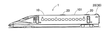
ここで、図1は、高速走行車両の先頭車両の側面図である。図2は、被覆部材の側面図であり、図3はその平面図、図4はその正面図である。
【0011】
(構成)本発明の一の実施の形態である静電アンテナの被覆部材の構成について説明する。静電アンテナ(図略)の被覆部材30は、図1に示すように、高速走行車両1の先頭車両および最後尾車両の車体10の次車両寄りの端部(以下、「後端部」という。)の天井部外表面101に取り付けられる。
被覆部材30は、図2に示すように、側面視で車両長手方向の中心線pに対して前後対称の山形をなし、その下端に形成され、左右が鍔状に広がった鍔部311を有する台座部31と、該台座部31の中心から上方に起立する静電アンテナ用突起35とからなるFRP製の中空箱体である。
【0012】
静電アンテナ用突起35は、側面視で、台座部31に連続する底辺352から徐々に前後方向の長さが短くなり、頂上部353に至る台形状を呈し、その水平断面の外形形状は図5に示すように車両の長手方向を長軸とする楕円弧状を、前記底辺352から頂上部353まで連続させたものである。
そして、静電アンテナ用突起35は、正面視で、その幅(厚み)が前記底辺352から徐々に減少しながら頂上部353に至るようになっており、したがって、水平断面における前後の前縁部351、351の楕円の短径は上部に行くにしたがって小さくなり、且つ側壁355を形成する長径も上部に行くにしたがって小さく形成される。
なお、頂上部353の前後方向の長さは、従来の被覆部材930の前縁部9351上端から、後部に突出したパイプ部9353の後端までの長さと略同一である。
また、前記台座部31には、この被覆部材30を車体10の外表面101で天井部に取り付けるための多数の取付孔314が設けられている。
【0013】
(作用)次に、本実施の形態の高速走行車両における車外突起部材の静電アンテナ用突起35の作用を説明する。
車両の高速走行に伴い、被覆部材30の前縁部351には空気が当接し、該空気を切り裂くようにして楕円の短径の前縁部351から両側の側壁355に沿って空気流が発生する。
前縁部351が楕円の短径となっているため、前縁部351で空気流は滑らかに両側の側壁355に沿うように流れ、剥離はほとんど生じない。前縁部351と対称形状の後部の前縁部351で、剥離せずに流れてきた空気流は大きく剥離することなく再び合流し、後方へと流れ去っていく。
【0014】
したがって、空力騒音の原因となる空気流の剥離による渦は殆ど発生せず、その結果、空力音を低減させることができた。この効果を実証するための騒音測定の結果を説明する。
すなわち、この騒音測定は、滋賀県米原町に所在する鉄道総合技術研究所内に設置された低騒音風洞において、新幹線「のぞみ(登録商標)」の走行速度である270Km/hに相当する風速を与えて行い、被覆部材の側方3.5mで測定した結果である。
その結果、図6のグラフの太い実線で示すように、270Km/h走行時の騒音は、従来の被覆部材930と比較して、約12dBA低減できることがわかった。
【0015】
このように、本実施の形態の高速走行車両1の静電アンテナ用突起35は、その平面断面形状を車両前後方向の中心線pに対して前後対称とし、さらに車両前後方向に長尺の楕円弧状としたので、高速走行時の空気の流れを剥離させることが無く、したがって空力音を低減させるとともに、高速走行車両1の前後いずれへの走行時にもこの効果を発揮することが可能となった。
【0016】
なお、本発明は前記実施の形態のものに限定されるものではなく、その趣旨を逸脱しない範囲で様々な変更が可能である。
例えば、前記実施の形態では、被覆部材の形状を静電アンテナの被覆部材に適用した例で説明したが、これに限られず、新幹線車両の4両目と5両目等の天井部外面に対向するように設けられた特高ケーブルのケーブルヘッドを被覆する被覆部材に適用することも可能である。
また、前記ケーブルヘッド以外の車両の両端に設けられる特高ケーブルの直ジョイントや通信アンテナ等の比較的高さの低い突起部材の水平断面形状を楕円弧状にすることも可能である。
【0017】
【発明の効果】
本発明は、静電アンテナと一体に形成されて鉄道車両の屋根から上方に突き出した高速走行車両の静電アンテナ用突起を、鉄道車両の車幅方向に薄い板形状であって、車両側面側から見た形状が車体前後方向の傾斜が対称の台形で、下側から頂上部に至るまで徐々に幅の厚みが薄くなり、水平断面の外形形状が車両の長手方向を長軸とする楕円弧状としたので、高速走行車両の高速走行時に発生する空気の流れによる前記被覆部材からの空気の剥離を極力少なくすることができ、その結果、空力騒音を低減することが可能となった。
【図面の簡単な説明】
【図1】 本発明の一の実施の形態に係る高速走行車両の側面図である。
【図2】 本発明の一の実施の形態に係る高速走行車両に適用した被覆部材の側面図である。
【図3】 本発明の一の実施の形態に係る高速走行車両に適用した被覆部材の平面図である。
【図4】 本発明の一の実施の形態に係る高速走行車両に適用した被覆部材の正面図である。
【図5】 図2のV−V線に沿う断面図である。
【図6】 本発明の一の実施の形態に係る被覆部材と従来の被覆部材の低騒音風洞における騒音試験の結果を示すグラフである。
【図7】 従来の被覆部材の側面図である。
【図8】 従来の被覆部材の平面図である。
【符号の説明】
1 高速走行車両
10 車体
20 突起部材
30 被覆部材
31 台座部
35 静電アンテナ用突起
351 前縁部
355 側壁[0001]
BACKGROUND OF THE INVENTION
TECHNICAL FIELD The present invention relates to the shape of a covering member that covers an external projection member such as an electrostatic antenna or an extra-high cable in a high-speed traveling vehicle such as a Shinkansen (registered trademark) , and more particularly to the static of a high-speed traveling vehicle that reduces aerodynamic noise during traveling. The present invention relates to a projection for an electric antenna.
[0002]
[Prior art]
In the problem of outside noise of a railway vehicle traveling at high speed, reduction of noise generated from around the vehicle, particularly aerodynamic noise such as wind noise generated during traveling is a major issue. This aerodynamic sound is generated when an air flow hits each part of the outer surface of the vehicle, and the cause of the occurrence is a stepped part or corner part and a sharp curved part on the surface of the vehicle body, or the outside of the vehicle. Various parts such as a handle, a step board, an antenna, etc., which are provided in the above.
As a technique for reducing the aerodynamic noise caused by the stepped portion as described above, there is a “step shape on the vehicle body side surface of a high-speed vehicle” described in Japanese Patent Laid-Open No. 2001-58568 (hereinafter referred to as “
[0003]
The technique described in
In the technique described in Patent Document 2, the surface of a part where air flow separation occurs in the outer surface of a moving body that moves at high speed has a net-like or slightly uneven structure (see “0005” in Patent Document 2). ”,“ 0006 ”and FIG. 1).
[0004]
[Patent Document 1]
Japanese Patent Laid-Open No. 2001-58568 [Patent Document 2]
Japanese Patent Application Laid-Open No. 7-17211
However, any of the above aerodynamic noise reduction techniques is applied to a stepped portion, a corner portion or a curved surface portion of a vehicle body, and does not correspond to a protruding portion protruding from the outer surface of the vehicle body such as a handle or an antenna. .
For example, the
The horizontal cross section is such that the
[0006]
[Problems to be solved by the invention]
As a result of measuring the aerodynamic sound of the conventional
[0007]
SUMMARY OF THE INVENTION Accordingly, an object of the present invention is to provide a projection for an electrostatic antenna of a high-speed traveling vehicle that minimizes separation of air flow as much as possible in order to solve such a problem.
[0008]
[Means for Solving the Problems]
The projection for the electrostatic antenna of the high-speed traveling vehicle according to the present invention is formed integrally with the electrostatic antenna and protrudes upward from the roof of the railway vehicle, and has a thin plate shape in the vehicle width direction of the railway vehicle. Thus, the shape seen from the side of the vehicle is a trapezoid with a symmetrical inclination in the longitudinal direction of the vehicle body, the width gradually decreases from the bottom to the top surface, and the outer shape of the horizontal section extends the longitudinal direction of the vehicle. It is characterized by having an elliptical arc shape as an axis.
[0009]
Therefore, even if one train of vehicles travels at a high speed in both the upward and downward directions, the air flow acting on the covering member is substantially the same, so that substantially the same aerodynamic sound can be obtained. In addition, since the air abutting the front edge in the vehicle traveling direction flows along the elliptical arc-shaped side wall, separation of the air flow is minimized at both the front edge and the rear edge. Can be reduced.
[0010]
DETAILED DESCRIPTION OF THE INVENTION
Next, an embodiment of a projection for an electrostatic antenna of a high-speed traveling vehicle according to the present invention will be described below with reference to the drawings. The electrostatic antenna protrusion of the vehicle outer protrusion member in the high-speed traveling vehicle of the present embodiment is applied to the covering member of the electrostatic antenna provided on the leading and trailing vehicles of the Shinkansen.
Here, FIG. 1 is a side view of the leading vehicle of the high-speed traveling vehicle. 2 is a side view of the covering member, FIG. 3 is a plan view thereof, and FIG. 4 is a front view thereof.
[0011]
(Structure) The structure of the covering member of the electrostatic antenna according to one embodiment of the present invention will be described. As shown in FIG. 1, the covering
As shown in FIG. 2, the covering
[0012]
The
Then, the
The length of the
The
[0013]
(Operation) Next, the operation of the
As the vehicle travels at high speed, air comes into contact with the
Since the
[0014]
Therefore, vortices due to separation of the air flow causing aerodynamic noise hardly occur, and as a result, aerodynamic noise can be reduced. The result of noise measurement for demonstrating this effect will be described.
In other words, this noise measurement gives a wind speed equivalent to 270 km / h, the running speed of the Shinkansen “ Nozomi (registered trademark) ”, in a low-noise wind tunnel installed in the Railway Technical Research Institute located in Yonehara-cho, Shiga Prefecture. This is a result of measurement performed at 3.5 m on the side of the covering member.
As a result, as shown by the thick solid line in the graph of FIG. 6, it was found that the noise during traveling at 270 km / h can be reduced by about 12 dBA compared to the
[0015]
As described above, the
[0016]
In addition, this invention is not limited to the thing of the said embodiment, A various change is possible in the range which does not deviate from the meaning.
For example, in the above-described embodiment, the example in which the shape of the covering member is applied to the covering member of the electrostatic antenna has been described. However, the present invention is not limited to this, and it faces the outer surface of the ceiling portion such as the fourth and fifth cars of the Shinkansen vehicle. It is also possible to apply to a covering member that covers the cable head of the extra high cable provided in the cable.
Further, it is also possible to make the horizontal cross-sectional shape of a relatively low projection member such as a direct joint of a special cable or a communication antenna provided at both ends of the vehicle other than the cable head into an elliptical arc shape.
[0017]
【The invention's effect】
The present invention provides a projection for an electrostatic antenna of a high-speed traveling vehicle that is integrally formed with an electrostatic antenna and protrudes upward from the roof of the railway vehicle, and has a thin plate shape in the vehicle width direction of the railway vehicle, The shape seen from the side is a trapezoid with a symmetrical inclination in the longitudinal direction of the car body, the width gradually decreases from the bottom to the top, and the outer shape of the horizontal section is an elliptical arc shape with the longitudinal direction of the vehicle as the major axis Therefore, it is possible to minimize the separation of the air from the covering member due to the air flow generated when the high-speed vehicle is traveling at high speed, and as a result, it is possible to reduce aerodynamic noise.
[Brief description of the drawings]
FIG. 1 is a side view of a high-speed traveling vehicle according to an embodiment of the present invention.
FIG. 2 is a side view of a covering member applied to a high-speed traveling vehicle according to an embodiment of the present invention.
FIG. 3 is a plan view of a covering member applied to a high-speed traveling vehicle according to an embodiment of the present invention.
FIG. 4 is a front view of a covering member applied to a high-speed traveling vehicle according to an embodiment of the present invention.
5 is a cross-sectional view taken along line VV in FIG.
FIG. 6 is a graph showing the results of a noise test in a low-noise wind tunnel of a covering member according to an embodiment of the present invention and a conventional covering member.
FIG. 7 is a side view of a conventional covering member.
FIG. 8 is a plan view of a conventional covering member.
[Explanation of symbols]
DESCRIPTION OF
Claims (1)
前記鉄道車両の車幅方向に薄い板形状であって、車両側面側から見た形状が車体前後方向の傾斜が対称の台形で、下側から頂上面に至るまで徐々に幅の厚みが薄くなり、水平断面の外形形状が車両の長手方向を長軸とする楕円弧状としたものであることを特徴とする高速走行車両の静電アンテナ用突起。In the projection for the electrostatic antenna of the high-speed traveling vehicle formed integrally with the electrostatic antenna and protruding upward from the roof of the railway vehicle,
It is a thin plate shape in the vehicle width direction of the railway vehicle, and the shape seen from the side surface of the vehicle is a trapezoid whose symmetry in the longitudinal direction of the vehicle body is symmetrical, and the thickness gradually decreases from the bottom to the top surface. A projection for an electrostatic antenna of a high-speed traveling vehicle, wherein the outer shape of the horizontal section is an elliptical arc having a longitudinal axis of the vehicle as a major axis.
Priority Applications (1)
| Application Number | Priority Date | Filing Date | Title |
|---|---|---|---|
| JP2003071978A JP4430880B2 (en) | 2003-03-17 | 2003-03-17 | Projection for electrostatic antenna of high-speed traveling vehicle |
Applications Claiming Priority (1)
| Application Number | Priority Date | Filing Date | Title |
|---|---|---|---|
| JP2003071978A JP4430880B2 (en) | 2003-03-17 | 2003-03-17 | Projection for electrostatic antenna of high-speed traveling vehicle |
Publications (2)
| Publication Number | Publication Date |
|---|---|
| JP2004276780A JP2004276780A (en) | 2004-10-07 |
| JP4430880B2 true JP4430880B2 (en) | 2010-03-10 |
Family
ID=33288286
Family Applications (1)
| Application Number | Title | Priority Date | Filing Date |
|---|---|---|---|
| JP2003071978A Expired - Fee Related JP4430880B2 (en) | 2003-03-17 | 2003-03-17 | Projection for electrostatic antenna of high-speed traveling vehicle |
Country Status (1)
| Country | Link |
|---|---|
| JP (1) | JP4430880B2 (en) |
Families Citing this family (5)
| Publication number | Priority date | Publication date | Assignee | Title |
|---|---|---|---|---|
| FR2976890B1 (en) * | 2011-06-21 | 2013-08-02 | Sncf | HOOD FOR ROOF OF A RAILWAY VEHICLE ADAPTED TO RADIO COMMUNICATIONS AND RAILWAY VEHICLE THEREFOR |
| KR101370592B1 (en) | 2012-10-19 | 2014-03-06 | 한국철도기술연구원 | Communication antenna for decrease of yawing |
| JP7120795B2 (en) * | 2018-04-27 | 2022-08-17 | 東海旅客鉄道株式会社 | electrostatic antenna |
| JP7038634B2 (en) * | 2018-09-21 | 2022-03-18 | 三菱電機株式会社 | Antenna device and railroad vehicle |
| JP7090522B2 (en) * | 2018-09-27 | 2022-06-24 | 三菱電機株式会社 | Antenna device and railroad vehicle |
-
2003
- 2003-03-17 JP JP2003071978A patent/JP4430880B2/en not_active Expired - Fee Related
Also Published As
| Publication number | Publication date |
|---|---|
| JP2004276780A (en) | 2004-10-07 |
Similar Documents
| Publication | Publication Date | Title |
|---|---|---|
| US9126603B2 (en) | Vehicle component having a recess overflowed with air | |
| CN109649509B (en) | Vehicle body structure | |
| JP4430880B2 (en) | Projection for electrostatic antenna of high-speed traveling vehicle | |
| JP2009029334A (en) | Lower part structure of vehicle body | |
| JP4531992B2 (en) | Aerodynamic noise reduction structure of recess with rod | |
| JP5935533B2 (en) | Vehicle roof device | |
| JP4222826B2 (en) | Railway vehicle | |
| JP3775930B2 (en) | Current collector | |
| JP6831761B2 (en) | Noise reduction device | |
| JP2000069602A (en) | Collector shoe for pantograph | |
| JP3685816B2 (en) | Top shape of the leading vehicle that forms a high-speed train | |
| JP3908214B2 (en) | Soundproof side wall of current collector | |
| JP5012720B2 (en) | Vehicle door mirror structure | |
| JP3779558B2 (en) | Insulator | |
| JP3807867B2 (en) | Pantograph with cover | |
| JPH09205702A (en) | Single arm type pantograph | |
| JP6931725B2 (en) | Current collection system | |
| JP2916759B2 (en) | Windproof cover for current collector | |
| JP2589839Y2 (en) | Pantograph windproof cover and aerodynamic noise reduction structure | |
| JP3671016B2 (en) | Railway vehicle | |
| JP5569338B2 (en) | Aerodynamic equipment for vehicles | |
| JP2023125059A (en) | Camping car | |
| JP3104089U (en) | Winged railway vehicle | |
| JPH0577729A (en) | Noise insulating device for rolling stock car | |
| JP2003291651A (en) | Noise reduction device |
Legal Events
| Date | Code | Title | Description |
|---|---|---|---|
| A621 | Written request for application examination |
Free format text: JAPANESE INTERMEDIATE CODE: A621 Effective date: 20040909 |
|
| A977 | Report on retrieval |
Free format text: JAPANESE INTERMEDIATE CODE: A971007 Effective date: 20070914 |
|
| A131 | Notification of reasons for refusal |
Free format text: JAPANESE INTERMEDIATE CODE: A131 Effective date: 20071009 |
|
| A521 | Written amendment |
Free format text: JAPANESE INTERMEDIATE CODE: A523 Effective date: 20071129 |
|
| A131 | Notification of reasons for refusal |
Free format text: JAPANESE INTERMEDIATE CODE: A131 Effective date: 20080415 |
|
| A521 | Written amendment |
Free format text: JAPANESE INTERMEDIATE CODE: A523 Effective date: 20080606 |
|
| A02 | Decision of refusal |
Free format text: JAPANESE INTERMEDIATE CODE: A02 Effective date: 20080902 |
|
| A521 | Written amendment |
Free format text: JAPANESE INTERMEDIATE CODE: A523 Effective date: 20081028 |
|
| A911 | Transfer of reconsideration by examiner before appeal (zenchi) |
Free format text: JAPANESE INTERMEDIATE CODE: A911 Effective date: 20081113 |
|
| A912 | Removal of reconsideration by examiner before appeal (zenchi) |
Free format text: JAPANESE INTERMEDIATE CODE: A912 Effective date: 20081219 |
|
| A01 | Written decision to grant a patent or to grant a registration (utility model) |
Free format text: JAPANESE INTERMEDIATE CODE: A01 |
|
| A61 | First payment of annual fees (during grant procedure) |
Free format text: JAPANESE INTERMEDIATE CODE: A61 Effective date: 20091218 |
|
| FPAY | Renewal fee payment (event date is renewal date of database) |
Free format text: PAYMENT UNTIL: 20121225 Year of fee payment: 3 |
|
| R150 | Certificate of patent or registration of utility model |
Ref document number: 4430880 Country of ref document: JP Free format text: JAPANESE INTERMEDIATE CODE: R150 Free format text: JAPANESE INTERMEDIATE CODE: R150 |
|
| FPAY | Renewal fee payment (event date is renewal date of database) |
Free format text: PAYMENT UNTIL: 20121225 Year of fee payment: 3 |
|
| FPAY | Renewal fee payment (event date is renewal date of database) |
Free format text: PAYMENT UNTIL: 20131225 Year of fee payment: 4 |
|
| R250 | Receipt of annual fees |
Free format text: JAPANESE INTERMEDIATE CODE: R250 |
|
| R250 | Receipt of annual fees |
Free format text: JAPANESE INTERMEDIATE CODE: R250 |
|
| R250 | Receipt of annual fees |
Free format text: JAPANESE INTERMEDIATE CODE: R250 |
|
| R250 | Receipt of annual fees |
Free format text: JAPANESE INTERMEDIATE CODE: R250 |
|
| R250 | Receipt of annual fees |
Free format text: JAPANESE INTERMEDIATE CODE: R250 |
|
| R250 | Receipt of annual fees |
Free format text: JAPANESE INTERMEDIATE CODE: R250 |
|
| LAPS | Cancellation because of no payment of annual fees |