EP3628520A1 - Rollo assembly and open roof construction provided therewith - Google Patents
Rollo assembly and open roof construction provided therewith Download PDFInfo
- Publication number
- EP3628520A1 EP3628520A1 EP18196624.3A EP18196624A EP3628520A1 EP 3628520 A1 EP3628520 A1 EP 3628520A1 EP 18196624 A EP18196624 A EP 18196624A EP 3628520 A1 EP3628520 A1 EP 3628520A1
- Authority
- EP
- European Patent Office
- Prior art keywords
- rollo
- assembly according
- connecting member
- rollo assembly
- connecting members
- Prior art date
- Legal status (The legal status is an assumption and is not a legal conclusion. Google has not performed a legal analysis and makes no representation as to the accuracy of the status listed.)
- Granted
Links
Images

Classifications
-
- B—PERFORMING OPERATIONS; TRANSPORTING
- B60—VEHICLES IN GENERAL
- B60J—WINDOWS, WINDSCREENS, NON-FIXED ROOFS, DOORS, OR SIMILAR DEVICES FOR VEHICLES; REMOVABLE EXTERNAL PROTECTIVE COVERINGS SPECIALLY ADAPTED FOR VEHICLES
- B60J7/00—Non-fixed roofs; Roofs with movable panels, e.g. rotary sunroofs
- B60J7/0007—Non-fixed roofs; Roofs with movable panels, e.g. rotary sunroofs moveable head-liners, screens, curtains or blinds for ceilings
- B60J7/0015—Non-fixed roofs; Roofs with movable panels, e.g. rotary sunroofs moveable head-liners, screens, curtains or blinds for ceilings roller blind
-
- B—PERFORMING OPERATIONS; TRANSPORTING
- B60—VEHICLES IN GENERAL
- B60J—WINDOWS, WINDSCREENS, NON-FIXED ROOFS, DOORS, OR SIMILAR DEVICES FOR VEHICLES; REMOVABLE EXTERNAL PROTECTIVE COVERINGS SPECIALLY ADAPTED FOR VEHICLES
- B60J7/00—Non-fixed roofs; Roofs with movable panels, e.g. rotary sunroofs
- B60J7/02—Non-fixed roofs; Roofs with movable panels, e.g. rotary sunroofs of sliding type, e.g. comprising guide shoes
- B60J7/04—Non-fixed roofs; Roofs with movable panels, e.g. rotary sunroofs of sliding type, e.g. comprising guide shoes with rigid plate-like element or elements, e.g. open roofs with harmonica-type folding rigid panels
- B60J7/043—Sunroofs e.g. sliding above the roof
-
- B—PERFORMING OPERATIONS; TRANSPORTING
- B60—VEHICLES IN GENERAL
- B60J—WINDOWS, WINDSCREENS, NON-FIXED ROOFS, DOORS, OR SIMILAR DEVICES FOR VEHICLES; REMOVABLE EXTERNAL PROTECTIVE COVERINGS SPECIALLY ADAPTED FOR VEHICLES
- B60J7/00—Non-fixed roofs; Roofs with movable panels, e.g. rotary sunroofs
- B60J7/02—Non-fixed roofs; Roofs with movable panels, e.g. rotary sunroofs of sliding type, e.g. comprising guide shoes
- B60J7/06—Non-fixed roofs; Roofs with movable panels, e.g. rotary sunroofs of sliding type, e.g. comprising guide shoes with non-rigid element or elements
- B60J7/067—Non-fixed roofs; Roofs with movable panels, e.g. rotary sunroofs of sliding type, e.g. comprising guide shoes with non-rigid element or elements sliding and winding up
Definitions
- the invention in a first aspect relates to a rollo assembly intended for use in an open roof construction for a vehicle with a roof opening defined in a stationary roof part, comprising a rotatable winding shaft, a rollo screen of which a rear end can be wound on or off said winding shaft and of which an opposite forward end is provided with an operating beam, opposite stationary guide channels for in a longitudinal direction guiding opposite side edges of the rollo screen and opposite ends of the operating beam, and drive cables extending in said guide channels and provided with connecting members for drivingly engaging respective counter connecting members provided at opposite ends of the operating beam, wherein the winding shaft, operating beam and rollo screen are combined into a detachable unit which, when the rollo screen is substantially fully wound onto the winding shaft and the drive cables assume a position in which the connecting members at least partially protrude from a longitudinal end of the guide channels facing the detachable unit, can be moved in a substantially vertical direction substantially perpendicularly to said longitudinal direction relative to said stationary guide channels for connecting or disconnecting the counter connecting
- a rollo assembly of such a type for example is known from DE 10 2015 109 862 A1 .
- the connecting members protrude from the guide channels, connecting the counter connecting members of the operating beam with the connecting members may prove difficult because the position and/or orientation of the connecting members (which then are mainly unsupported by the guide channels) may vary.
- One solution to this problem would be to prolong the guide channels while removing (for example milling away) an upper part thereof, such that the remaining lower part of the guide channel still supports the connecting member while offering access to the connecting member at the removed upper part of the guide channel.
- a drawback of such a solution is the increased cost of material for the guide channels (which originally should be longer) and the increased manufacturing cost for removing (milling away) part of the guide channels.
- the rollo assembly further comprises supporting means for maintaining the connecting members of the drive cables, when maximally protruding from said longitudinal end of the guide channels, in a well-defined position.
- the supporting means which are means other than the guide channels, maintain the connecting members in a well-defined position, especially during a connection operation.
- the guide channels can simply be cut off to a desired length.
- the supporting means comprise at least one part of, preferably the stationary roof part of, the vehicle for supporting the connecting members in said vertical direction.
- said at least one part of the vehicle may be a transverse beam which preferably defines part of the roof opening.
- said transverse beam may be a rear beam of the roof opening (in an embodiment in which the rotatable winding shaft is located behind the roof opening), but the use of, for example, a middle beam is conceivable too.
- the supporting means comprise abutment members for defining the longitudinal position of the connecting members when maximally protruding from said longitudinal end of the guide channels.
- abutment members may be provided on at least one part of, preferably the stationary roof part of, the vehicle, such as, for example, a transverse beam which preferably defines part of the roof opening. This again may be a rear beam of the roof opening.
- said abutment members are part of the guide channels. This, however, may increase the cost of the guide channels, which apart from being cut off to the desired length also should be provided with such abutment members.
- each connecting member has such a length that, when maximally protruding from the guide channel, part of the connecting member still is housed in the respective guide channel and wherein said part of the connecting member and the guide channel define such a tight fit that a rotation of the connecting member around the longitudinal direction as defined by the respective drive cable is substantially prevented.
- the guide channels play a role in maintaining the connecting members in a desired position and orientation, especially during a connecting operation.
- the connecting members When, in the position in which the connecting members at least partially protrude from the said longitudinal end of the guide channels, the counter connecting members of the operating beam have been connected with the connecting members, the connecting members have to be moved in the longitudinal direction for (further) entering the guide channels together with the ends of the operating beam and the rollo screen edges.
- the connecting members When the connecting members have a stationary position with respect to the drive cables, such a longitudinal movement of the connecting members involves a longitudinal movement of the drive cables.
- a movement of the drive cables generally would involve the activation of a drive mechanism, such as an electric motor, and in practice such an activation is not preferred at such a stage.
- each connecting member in said longitudinal direction in a limited sense is slidable relative to the respective drive cable.
- the connecting member together with the counter connecting member can be moved (further) into the guide channel while the drive cable is kept stationary.
- the connecting member is directly slidably connected to the drive cable.
- the connecting member may have a channel through which the drive cable runs.
- the drive cable carries a base member fixed thereto wherein the connecting member is defined by a slide member which can slide on said base member.
- the base member in a position in which the connecting member at least partially protrudes from a longitudinal end of the guide channel facing the detachable unit is housed completely within the guide channel without protruding from said longitudinal end.
- Such an embodiment enables a mounting operation of the detachable unit in such a manner that, after the counter connecting member and connecting member are interconnected by an appropriate movement of the operating beam in a vertical direction (most commonly downward) and the connecting member has moved (further) into the guide channel, the winding shaft firstly is moved closer towards the guide channel (as allowed because the base member does not protrude therefrom) before also being moved in said vertical direction to its final position.
- each connecting member defines a projecting member, whereas each counter connecting member of the operating beam defines a corresponding recess for receiving a connecting member.
- the invention in a second aspect relates to an open roof construction for a vehicle, comprising a roof opening provided in a stationary roof part, a movable panel intended for closing and at least partially opening said roof opening and with a rollo assembly according to the present invention positioned below said roof opening.
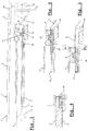
- FIG 1 a schematic representation is shown of an open roof construction with a rollo assembly, intended for use in a vehicle, with a roof opening 1 defined in a stationary roof part 2.
- a movable panel 3 is provided intended for closing and at least partially opening said roof opening 1 in a manner known per se.
- the rollo assembly comprises a rotatable winding shaft 4, a rollo screen 5 of which a rear end can be wound on or off said winding shaft and of which an opposite forward end is provided with an operating beam 6.
- opposite stationary guide channels 7 are provided at opposite longitudinal sides of and below the roof opening 1 for in a longitudinal direction L guiding opposite side edges of the rollo screen 5 and opposite ends of the operating beam 6.
- Drive cables 8 driven by, for example, an electric motor 9 (or alternatively manually by a hand crank) extend in said guide channels 7 and are provided with connecting members 10 for drivingly engaging the operating beam 6 (more specifically counter connecting members 11 provided at opposite ends of the operating beam 6).
- the winding shaft 4, operating beam 6 and rollo screen 5 are combined into a detachable unit 12 (schematically indicated by a broken line) which, when the rollo screen 5 is substantially fully wound onto the winding shaft 4 and the drive cables 8 assume a position in which the connecting members 10 at least partially protrude from a longitudinal (here rear) end of the guide channels 7 facing the detachable unit 12 (as represented in figure 1 ), can be moved in a substantially vertical direction V substantially perpendicularly to said longitudinal direction L relative to said stationary guide channels 7 for connecting or disconnecting the counter connecting members 11 of the operating beam 6 to or from the connecting members 10 of the drive cables 8.
- the connecting members 10 define projections 13, while the counter connecting members 11 are shaped as recesses for receiving said projections 13.
- the connecting members 10 likewise may define recesses while the counter connecting members 11 define projections.
- other mating members or provisions for connecting these parts are conceivable.
- the rollo assembly further comprises supporting means for maintaining the connecting members 10 of the drive cables 8, when maximally protruding from said longitudinal end of the guide channels 7 as illustrated in figure 1 , in a well-defined position.
- Such supporting means may comprise at least one part 14, preferably of the stationary roof part 2 of the vehicle for supporting the connecting members 10 in said vertical direction V.
- Said at least one part 14 of the vehicle can be a transverse beam (in the present embodiment a rear beam) which defines part of the (boundary of the) roof opening 1. But also, for example, a middle beam is conceivable.
- Said supporting means further may comprise abutment members 15 for defining the longitudinal position of the connecting members 10 when maximally protruding from said longitudinal end of the guide channels 7 ( figure 1 ).
- abutment members 15 may be provided on said at least one part 14 of the stationary roof part 2 of the vehicle, but it also is conceivable that these abutment members 15 are attached to, or are part of another part of the vehicle.
- said abutment members also may be part of the guide channels 7.
- the connecting member 10 in the illustrated embodiment has such a length that, when maximally protruding from its guide channel 7, part of the connecting member still is housed in the respective guide channel 7. Further, referring to figure 4 , said part of the connecting member 10 and the guide channel 7 define such a tight fit that a rotation of the connecting member around a longitudinal direction as defined by the respective drive cable 8 is substantially prevented.
- the part 14, the abutment member 15 and the discussed tight fit between the connecting member 10 and guide channel 7 assure that the position and orientation of the connecting member 10 are maintained during a connecting operation as described below.
- each connecting member 10 in a limited sense is slidable in the longitudinal direction L relative to the respective drive cable 8.
- the drive cable 8 carries a base member 16 fixed thereto and the connecting member 10 is shaped as a slide member which can slide on said base member 16 .
- the base member 16 comprises a stop 17 which defines the outermost (rearmost) position of the connecting member 10 as illustrated in figure 5 . In this position the connecting operation has started and has proceeded until the connecting member 10 (or its projection 13) and counter connecting member (recess) 11 of the operating beam 6 have been engaged.
- the connecting member (slide) 10 is slid over the base member 16 in a direction (further) into the guide channel 7 without moving the drive cable ( figure 6 ). Thus any activation of the drive cable 8 can be avoided at this stage.
- winding shaft 4 will be spring-loaded for winding on the rollo screen 5 and as a result the connecting member 10 will be kept in engagement with the stop 17 during a movement of the drive cable 8 and the rollo screen 5.
- FIG 8 an alternative embodiment is illustrated in which the connecting member 10 is directly slidably connected to/mounted on the drive cable 8 without the use of a base member.
- FIG. 9 yet another embodiment is illustrated which also shows a connecting member 10 which is slidable on a base member 16.
- the base member 16 in a position in which the connecting member 10 at least partially protrudes from a longitudinal end of the guide channel 7 facing the detachable unit 12 (as illustrated in figure 9 ) is housed completely within the guide channel without protruding from said longitudinal end.
- Such an embodiment allows to mount the detachable unit in the following manner: firstly the operating beam 6 (which, as discussed above, is provided with the counter connecting members 11) is lowered such that its counter connecting members 11 engage the connecting members 10 (as represented in figure 9 as a movement from position 6' to position 6).
- the winding shaft 4 is kept stationary (this basically may apply for other parts of the unit 12 too, however with the exception of the operating beam 6).
- the connecting member 10 is slid over the base member 16 into the guide channel 7 (reaching the position indicated in figure 10 ), where after the winding shaft 4 is moved towards the guide channel 7 (as represented in figure 10 as the movement from position 4' to position 4).
- the winding shaft is lowered to its final position (movement from position 4' to position 4 in figure 11 ).
- the rollo assembly is ready for use, meaning that the base member 16 can move to the left, which eventually will lead to a corresponding movement of the connecting member 10 and thus, via the counter connecting member 11 of the operating beam 6, of the rollo screen 5.
- part supporting the connecting member also may be part of another vehicle part and is not limited to being part of the stationary roof part.
Landscapes
- Engineering & Computer Science (AREA)
- Mechanical Engineering (AREA)
- Operating, Guiding And Securing Of Roll- Type Closing Members (AREA)
Abstract
Description
- The invention in a first aspect relates to a rollo assembly intended for use in an open roof construction for a vehicle with a roof opening defined in a stationary roof part, comprising a rotatable winding shaft, a rollo screen of which a rear end can be wound on or off said winding shaft and of which an opposite forward end is provided with an operating beam, opposite stationary guide channels for in a longitudinal direction guiding opposite side edges of the rollo screen and opposite ends of the operating beam, and drive cables extending in said guide channels and provided with connecting members for drivingly engaging respective counter connecting members provided at opposite ends of the operating beam, wherein the winding shaft, operating beam and rollo screen are combined into a detachable unit which, when the rollo screen is substantially fully wound onto the winding shaft and the drive cables assume a position in which the connecting members at least partially protrude from a longitudinal end of the guide channels facing the detachable unit, can be moved in a substantially vertical direction substantially perpendicularly to said longitudinal direction relative to said stationary guide channels for connecting or disconnecting the counter connecting members of the operating beam to or from the connecting members of the drive cables.
- A rollo assembly of such a type for example is known from
DE 10 2015 109 862 A1 . When, in this known rollo assembly, the connecting members protrude from the guide channels, connecting the counter connecting members of the operating beam with the connecting members may prove difficult because the position and/or orientation of the connecting members (which then are mainly unsupported by the guide channels) may vary. One solution to this problem would be to prolong the guide channels while removing (for example milling away) an upper part thereof, such that the remaining lower part of the guide channel still supports the connecting member while offering access to the connecting member at the removed upper part of the guide channel. A drawback of such a solution, however, is the increased cost of material for the guide channels (which originally should be longer) and the increased manufacturing cost for removing (milling away) part of the guide channels. - It is an object of the present invention to provide an improved rollo assembly of the above-mentioned type.
- Thus, in accordance with the present invention, the rollo assembly further comprises supporting means for maintaining the connecting members of the drive cables, when maximally protruding from said longitudinal end of the guide channels, in a well-defined position.
- The supporting means, which are means other than the guide channels, maintain the connecting members in a well-defined position, especially during a connection operation. The guide channels can simply be cut off to a desired length.
- In one embodiment the supporting means comprise at least one part of, preferably the stationary roof part of, the vehicle for supporting the connecting members in said vertical direction. For example said at least one part of the vehicle may be a transverse beam which preferably defines part of the roof opening. Specifically said transverse beam may be a rear beam of the roof opening (in an embodiment in which the rotatable winding shaft is located behind the roof opening), but the use of, for example, a middle beam is conceivable too.
- In another embodiment the supporting means comprise abutment members for defining the longitudinal position of the connecting members when maximally protruding from said longitudinal end of the guide channels. For example, such abutment members may be provided on at least one part of, preferably the stationary roof part of, the vehicle, such as, for example, a transverse beam which preferably defines part of the roof opening. This again may be a rear beam of the roof opening.
- In an alternative embodiment said abutment members are part of the guide channels. This, however, may increase the cost of the guide channels, which apart from being cut off to the desired length also should be provided with such abutment members.
- In one embodiment of the rollo assembly each connecting member has such a length that, when maximally protruding from the guide channel, part of the connecting member still is housed in the respective guide channel and wherein said part of the connecting member and the guide channel define such a tight fit that a rotation of the connecting member around the longitudinal direction as defined by the respective drive cable is substantially prevented.
- In such an embodiment also the guide channels play a role in maintaining the connecting members in a desired position and orientation, especially during a connecting operation.
- When, in the position in which the connecting members at least partially protrude from the said longitudinal end of the guide channels, the counter connecting members of the operating beam have been connected with the connecting members, the connecting members have to be moved in the longitudinal direction for (further) entering the guide channels together with the ends of the operating beam and the rollo screen edges. When the connecting members have a stationary position with respect to the drive cables, such a longitudinal movement of the connecting members involves a longitudinal movement of the drive cables. However, during mounting the rollo assembly a movement of the drive cables generally would involve the activation of a drive mechanism, such as an electric motor, and in practice such an activation is not preferred at such a stage.
- For avoiding such a situation, an embodiment is conceivable in which each connecting member in said longitudinal direction in a limited sense is slidable relative to the respective drive cable. Thus the connecting member together with the counter connecting member can be moved (further) into the guide channel while the drive cable is kept stationary.
- It is possible, then, that the connecting member is directly slidably connected to the drive cable. For example the connecting member may have a channel through which the drive cable runs.
- In an alternative embodiment the drive cable carries a base member fixed thereto wherein the connecting member is defined by a slide member which can slide on said base member.
- In a specific embodiment, then, the base member in a position in which the connecting member at least partially protrudes from a longitudinal end of the guide channel facing the detachable unit is housed completely within the guide channel without protruding from said longitudinal end.
- Such an embodiment enables a mounting operation of the detachable unit in such a manner that, after the counter connecting member and connecting member are interconnected by an appropriate movement of the operating beam in a vertical direction (most commonly downward) and the connecting member has moved (further) into the guide channel, the winding shaft firstly is moved closer towards the guide channel (as allowed because the base member does not protrude therefrom) before also being moved in said vertical direction to its final position.
- In one embodiment each connecting member defines a projecting member, whereas each counter connecting member of the operating beam defines a corresponding recess for receiving a connecting member.
- In a second aspect the invention relates to an open roof construction for a vehicle, comprising a roof opening provided in a stationary roof part, a movable panel intended for closing and at least partially opening said roof opening and with a rollo assembly according to the present invention positioned below said roof opening.
- Hereinafter the invention will be elucidated while referring to the drawings, in which:
-
Figure 1 in a schematic manner illustrates an embodiment of an open roof construction with rollo assembly according to the invention in a longitudinal cross section and in a first position; -
Figures 2 and 3 in a similar manner but at a slightly larger scale illustrate part of the open roof construction offigure 1 , but in two different positions; -
Figure 4 illustrates a cross section according to IV-IV infigure 3 ; -
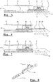
Figures 5-7 illustrate a different embodiment of the rollo assembly in three different positions; -
Figure 8 in a perspective view illustrates a detail of yet another embodiment of the rollo assembly, and -
Figures 9-11 illustrate yet a different embodiment of the rollo assembly in three different positions. - In
figure 1 a schematic representation is shown of an open roof construction with a rollo assembly, intended for use in a vehicle, with aroof opening 1 defined in astationary roof part 2. Amovable panel 3 is provided intended for closing and at least partially opening said roof opening 1 in a manner known per se. The rollo assembly comprises arotatable winding shaft 4, arollo screen 5 of which a rear end can be wound on or off said winding shaft and of which an opposite forward end is provided with anoperating beam 6. - Further, opposite stationary guide channels 7 (only one of which is visible) are provided at opposite longitudinal sides of and below the roof opening 1 for in a longitudinal direction L guiding opposite side edges of the
rollo screen 5 and opposite ends of theoperating beam 6.Drive cables 8 driven by, for example, an electric motor 9 (or alternatively manually by a hand crank) extend in saidguide channels 7 and are provided with connectingmembers 10 for drivingly engaging the operating beam 6 (more specifically counter connectingmembers 11 provided at opposite ends of the operating beam 6). - The
winding shaft 4,operating beam 6 androllo screen 5 are combined into a detachable unit 12 (schematically indicated by a broken line) which, when therollo screen 5 is substantially fully wound onto thewinding shaft 4 and thedrive cables 8 assume a position in which the connectingmembers 10 at least partially protrude from a longitudinal (here rear) end of theguide channels 7 facing the detachable unit 12 (as represented infigure 1 ), can be moved in a substantially vertical direction V substantially perpendicularly to said longitudinal direction L relative to saidstationary guide channels 7 for connecting or disconnecting thecounter connecting members 11 of theoperating beam 6 to or from the connectingmembers 10 of thedrive cables 8. - In the embodiment according to
figure 1 the connectingmembers 10 defineprojections 13, while thecounter connecting members 11 are shaped as recesses for receiving saidprojections 13. However, the connectingmembers 10 likewise may define recesses while thecounter connecting members 11 define projections. Also other mating members or provisions for connecting these parts are conceivable. - The rollo assembly further comprises supporting means for maintaining the connecting
members 10 of thedrive cables 8, when maximally protruding from said longitudinal end of theguide channels 7 as illustrated infigure 1 , in a well-defined position. Such supporting means may comprise at least onepart 14, preferably of thestationary roof part 2 of the vehicle for supporting the connectingmembers 10 in said vertical direction V. Said at least onepart 14 of the vehicle can be a transverse beam (in the present embodiment a rear beam) which defines part of the (boundary of the)roof opening 1. But also, for example, a middle beam is conceivable. - Said supporting means further may comprise
abutment members 15 for defining the longitudinal position of the connectingmembers 10 when maximally protruding from said longitudinal end of the guide channels 7 (figure 1 ).Such abutment members 15 may be provided on said at least onepart 14 of thestationary roof part 2 of the vehicle, but it also is conceivable that theseabutment members 15 are attached to, or are part of another part of the vehicle. For example, said abutment members also may be part of theguide channels 7. - As appears from
figure 1 , the connectingmember 10 in the illustrated embodiment has such a length that, when maximally protruding from itsguide channel 7, part of the connecting member still is housed in therespective guide channel 7. Further, referring tofigure 4 , said part of the connectingmember 10 and theguide channel 7 define such a tight fit that a rotation of the connecting member around a longitudinal direction as defined by therespective drive cable 8 is substantially prevented. - Thus, the
part 14, theabutment member 15 and the discussed tight fit between the connectingmember 10 andguide channel 7 assure that the position and orientation of the connectingmember 10 are maintained during a connecting operation as described below. - Starting from the position in
figure 1 in which the connecting member 10 (more precisely its projection 13) is still disengaged from the counter connecting member (recess) 11 of theoperating beam 6, thecounter connecting member 11 is lowered to the position illustrated infigure 2 . Next the connectingmember 10, through a movement of thedrive cable 8, is moved further into theguide channel 7, as illustrated infigure 3 . The rollo assembly now is ready for use. The manner in which thedetachable unit 12 is connected to the remainder of the rollo assembly is known per se and has not been illustrated. - In some situations, while mounting the
detachable unit 12 to the remainder of the rollo assembly, one wishes to avoid the need of moving the drive cables 8 (either by anelectric motor 9 or manually by a hand crank) for moving the connecting members 10 (further) into theguide channels 7. Thus an embodiment may be provided as illustrated infigures 5-7 which show consecutive positions thereof during a connecting operation. - In this embodiment each connecting
member 10 in a limited sense is slidable in the longitudinal direction L relative to therespective drive cable 8. As illustrated, thedrive cable 8 carries abase member 16 fixed thereto and the connectingmember 10 is shaped as a slide member which can slide on saidbase member 16 . Thebase member 16 comprises astop 17 which defines the outermost (rearmost) position of the connectingmember 10 as illustrated infigure 5 . In this position the connecting operation has started and has proceeded until the connecting member 10 (or its projection 13) and counter connecting member (recess) 11 of theoperating beam 6 have been engaged. - Next the connecting member (slide) 10 is slid over the
base member 16 in a direction (further) into theguide channel 7 without moving the drive cable (figure 6 ). Thus any activation of thedrive cable 8 can be avoided at this stage. - Starting from the position in
figure 6 , in which the connecting member has fully entered theguide channel 7, a movement of thedrive cable 8 to the left will lead to the situation illustrated infigure 7 in which thestop 17 again engages the connectingmember 10, such that latter will move along with the drive cable for an operation of the rollo assembly (that is, a movement of the rollo screen 5). - In some instances the winding
shaft 4 will be spring-loaded for winding on therollo screen 5 and as a result the connectingmember 10 will be kept in engagement with thestop 17 during a movement of thedrive cable 8 and therollo screen 5. - In
figure 8 an alternative embodiment is illustrated in which the connectingmember 10 is directly slidably connected to/mounted on thedrive cable 8 without the use of a base member. - Finally referring to
figures 9-11 , yet another embodiment is illustrated which also shows a connectingmember 10 which is slidable on abase member 16. However, in this particular embodiment thebase member 16 in a position in which the connectingmember 10 at least partially protrudes from a longitudinal end of theguide channel 7 facing the detachable unit 12 (as illustrated infigure 9 ) is housed completely within the guide channel without protruding from said longitudinal end. Such an embodiment allows to mount the detachable unit in the following manner: firstly the operating beam 6 (which, as discussed above, is provided with the counter connecting members 11) is lowered such that itscounter connecting members 11 engage the connecting members 10 (as represented infigure 9 as a movement from position 6' to position 6). The windingshaft 4 is kept stationary (this basically may apply for other parts of theunit 12 too, however with the exception of the operating beam 6). Next the connectingmember 10 is slid over thebase member 16 into the guide channel 7 (reaching the position indicated infigure 10 ), where after the windingshaft 4 is moved towards the guide channel 7 (as represented infigure 10 as the movement from position 4' to position 4). Finally, the winding shaft is lowered to its final position (movement from position 4' toposition 4 infigure 11 ). After the winding shaft 4 (or the detachable unit 12) is fixed in this final position, the rollo assembly is ready for use, meaning that thebase member 16 can move to the left, which eventually will lead to a corresponding movement of the connectingmember 10 and thus, via thecounter connecting member 11 of theoperating beam 6, of therollo screen 5. - The invention is not limited to the embodiments described before which may be varied widely within the scope of the invention as defined by the appending claims. Thus it will be clear that the part supporting the connecting member also may be part of another vehicle part and is not limited to being part of the stationary roof part.
Claims (15)
- Rollo assembly intended for use in an open roof construction for a vehicle with a roof opening (1) defined in a stationary roof part (2), comprising a rotatable winding shaft (4), a rollo screen (5) of which a rear end can be wound on or off said winding shaft and of which an opposite forward end is provided with an operating beam (6), opposite stationary guide channels (7) for in a longitudinal direction guiding opposite side edges of the rollo screen and opposite ends of the operating beam, and drive cables (8) extending in said guide channels and provided with connecting members (10) for drivingly engaging respective counter connecting members (11) provided at opposite ends of the operating beam, wherein the winding shaft (4), operating beam (6) and rollo screen (5) are combined into a detachable unit (12) which, when the rollo screen is substantially fully wound onto the winding shaft and the drive cables assume a position in which the connecting members at least partially protrude from a longitudinal end of the guide channels facing the detachable unit, can be moved in a substantially vertical direction substantially perpendicularly to said longitudinal direction relative to said stationary guide channels for connecting or disconnecting the counter connecting members of the operating beam to or from the connecting members of the drive cables, characterized in that the rollo assembly further comprises supporting means (14, 15) for maintaining the connecting members (10) of the drive cables (8), when maximally protruding from said longitudinal end of the guide channels (7), in a well-defined position.
- Rollo assembly according to claim 1, wherein the supporting means comprise at least one part (14) of, preferably the stationary roof part (2) of, the vehicle for supporting the connecting members (10) in said vertical direction.
- Rollo assembly according to claim 2, wherein said at least one part (14) of the vehicle is a transverse beam which preferably defines part of the roof opening (1).
- Rollo assembly according to claim 3, wherein said transverse beam is a rear beam of the roof opening (1).
- Rollo assembly according to any of the previous claims, wherein the supporting means comprise abutment members (15) for defining the longitudinal position of the connecting members (10) when maximally protruding from said longitudinal end of the guide channels (7).
- Rollo assembly according to claim 5, wherein said abutment members (15) are provided on at least one part (14), preferably of the stationary roof part (2), of the vehicle.
- Rollo assembly according to claim 6, wherein said at least one part (14) of the vehicle is a transverse beam which preferably defines part of the roof opening (1) and preferably is a rear beam of the roof opening (1).
- Rollo assembly according to claim 5, wherein said abutment members are part of the guide channels (7).
- Rollo assembly according to any of the previous claims, wherein each connecting member (10) has such a length that, when maximally protruding from the guide channel (7), part of the connecting member still is housed in the respective guide channel and wherein said part of the connecting member and the guide channel define such a tight fit that a rotation of the connecting member around the longitudinal direction as defined by the respective drive cable (8) is substantially prevented.
- Rollo assembly according to any of the previous claims, wherein each connecting member (10) in said longitudinal direction in a limited sense is slidable relative to the respective drive cable (8).
- Rollo assembly according to claim 10, wherein the connecting member (10) is directly slidably connected to the drive cable (8).
- Rollo assembly according to claim 10, wherein the drive cable (8) carries a base member (16) fixed thereto and wherein the connecting member (10) is defined by a slide member which can slide on said base member.
- Rollo assembly according to claim 12, wherein the base member (16) in a position in which the connecting member (10) at least partially protrudes from a longitudinal end of the guide channel (7) facing the detachable unit (12) is housed completely within the guide channel without protruding from said longitudinal end.
- Rollo assembly according to any of the previous claims, wherein each connecting member (10) defines a projecting member (13), whereas each counter connecting member (11) of the operating beam (6) defines a corresponding recess for receiving a connecting member.
- Open roof construction for a vehicle, comprising a roof opening (1) provided in a stationary roof part (2), a movable panel (3) intended for closing and at least partially opening said roof opening and with a rollo assembly according to any of the previous claim positioned below said roof opening.
Priority Applications (3)
| Application Number | Priority Date | Filing Date | Title |
|---|---|---|---|
| EP18196624.3A EP3628520B1 (en) | 2018-09-25 | 2018-09-25 | Rollo assembly and open roof construction provided therewith |
| CN201910807822.3A CN110936795B (en) | 2018-09-25 | 2019-08-29 | Rolling shutter assembly and open roof construction provided with same |
| US16/579,152 US11390148B2 (en) | 2018-09-25 | 2019-09-23 | Rollo assembly and open roof construction provided therewith |
Applications Claiming Priority (1)
| Application Number | Priority Date | Filing Date | Title |
|---|---|---|---|
| EP18196624.3A EP3628520B1 (en) | 2018-09-25 | 2018-09-25 | Rollo assembly and open roof construction provided therewith |
Publications (2)
| Publication Number | Publication Date |
|---|---|
| EP3628520A1 true EP3628520A1 (en) | 2020-04-01 |
| EP3628520B1 EP3628520B1 (en) | 2021-05-26 |
Family
ID=63683785
Family Applications (1)
| Application Number | Title | Priority Date | Filing Date |
|---|---|---|---|
| EP18196624.3A Active EP3628520B1 (en) | 2018-09-25 | 2018-09-25 | Rollo assembly and open roof construction provided therewith |
Country Status (3)
| Country | Link |
|---|---|
| US (1) | US11390148B2 (en) |
| EP (1) | EP3628520B1 (en) |
| CN (1) | CN110936795B (en) |
Citations (3)
| Publication number | Priority date | Publication date | Assignee | Title |
|---|---|---|---|---|
| DE102014005476A1 (en) * | 2014-04-15 | 2015-10-15 | Webasto SE | Roller blind device on a vehicle roof |
| DE102015109862A1 (en) | 2015-06-19 | 2016-12-22 | Webasto SE | Vehicle roof with roller blind arrangement |
| EP3176016A1 (en) * | 2015-12-03 | 2017-06-07 | Inalfa Roof Systems Group B.V. | Rollo assembly |
Family Cites Families (6)
| Publication number | Priority date | Publication date | Assignee | Title |
|---|---|---|---|---|
| US4159144A (en) | 1977-09-01 | 1979-06-26 | General Motors Corporation | Vehicle body sunroof |
| JPS5823248B2 (en) | 1979-01-22 | 1983-05-13 | マツダ株式会社 | Guide rail structure for automobile sliding grooves |
| DE19927234C1 (en) | 1999-06-15 | 2000-07-27 | Webasto Vehicle Sys Int Gmbh | Guide rail for accommodating displaceable vehicle roof part(s) has first section with centring element that interacts with complementary counter element on second section |
| DE102012019078A1 (en) | 2012-09-27 | 2013-03-21 | Daimler Ag | Roof module for roof of passenger car, has sun protection device held in pre-assembly position, where sun protection device is movable relative to roof module in final assembly position during assembly of roof module |
| WO2016107650A1 (en) * | 2014-12-30 | 2016-07-07 | Inalfa Roof Systems Group B.V. | Rollo assembly and open roof construction for a vehicle provided therewith |
| US10053909B2 (en) * | 2016-08-25 | 2018-08-21 | J. Paxton Enterprises, Inc. | Triple-shade roller blind |
-
2018
- 2018-09-25 EP EP18196624.3A patent/EP3628520B1/en active Active
-
2019
- 2019-08-29 CN CN201910807822.3A patent/CN110936795B/en active Active
- 2019-09-23 US US16/579,152 patent/US11390148B2/en active Active
Patent Citations (3)
| Publication number | Priority date | Publication date | Assignee | Title |
|---|---|---|---|---|
| DE102014005476A1 (en) * | 2014-04-15 | 2015-10-15 | Webasto SE | Roller blind device on a vehicle roof |
| DE102015109862A1 (en) | 2015-06-19 | 2016-12-22 | Webasto SE | Vehicle roof with roller blind arrangement |
| EP3176016A1 (en) * | 2015-12-03 | 2017-06-07 | Inalfa Roof Systems Group B.V. | Rollo assembly |
Also Published As
| Publication number | Publication date |
|---|---|
| US20200094659A1 (en) | 2020-03-26 |
| CN110936795A (en) | 2020-03-31 |
| CN110936795B (en) | 2023-10-31 |
| EP3628520B1 (en) | 2021-05-26 |
| US11390148B2 (en) | 2022-07-19 |
Similar Documents
| Publication | Publication Date | Title |
|---|---|---|
| US6119402A (en) | Power sliding rear window | |
| US4081926A (en) | Sunroof | |
| CA1045653A (en) | Sliding roof for automobiles | |
| US10569622B2 (en) | Vehicle roof having a roller blind arrangement | |
| US4671565A (en) | Cable guide for sliding roofs of motor vehicles | |
| EP2151339B1 (en) | Sunshade assembly and open roof construction provided therewith | |
| US4531777A (en) | Motor vehicle roof arrangement of the type interchangeably driveable by both motor and crank drives | |
| EP2883727B1 (en) | Drive mechanism and open roof construction provided therewith | |
| EP3176016B1 (en) | Rollo assembly | |
| EP3100883B1 (en) | Rollo assembly and open roof construction for a vehicle provided therewith | |
| US7665793B2 (en) | Roller blind system for a vehicle roof | |
| SE450234B (en) | FOR MOTOR VEHICLES PROVIDED SLIDE-LIFT ROOF WITH A LARGE ROOF COVER | |
| DE10110012A1 (en) | Vehicle roof with two movable covers | |
| EP2481618A2 (en) | Roof apparatus | |
| EP3628520B1 (en) | Rollo assembly and open roof construction provided therewith | |
| EP2845759B1 (en) | Sunroof apparatus for vehicle | |
| EP0754583B1 (en) | Tilt-sliding roof, and vehicle comprising such a tilt-sliding roof | |
| EP2711218B1 (en) | Drive mechanism and open roof construction provided therewith | |
| GB2232645A (en) | Air guide device for an automobile roof which has a sliding panel | |
| US8800635B2 (en) | Lateral guide for shading roller blind, and shading roller blind for motor vehicles | |
| EP2845760B1 (en) | Sunroof apparatus for vehicle | |
| JP3840350B2 (en) | Shielding device for vehicle opening | |
| JP2010201956A (en) | Automobile sun shade device | |
| EP2062766B1 (en) | Sunscreen assembly with two sunscreens | |
| CN109291772B (en) | Open roof construction for a vehicle |
Legal Events
| Date | Code | Title | Description |
|---|---|---|---|
| PUAI | Public reference made under article 153(3) epc to a published international application that has entered the european phase |
Free format text: ORIGINAL CODE: 0009012 |
|
| STAA | Information on the status of an ep patent application or granted ep patent |
Free format text: STATUS: THE APPLICATION HAS BEEN PUBLISHED |
|
| AK | Designated contracting states |
Kind code of ref document: A1 Designated state(s): AL AT BE BG CH CY CZ DE DK EE ES FI FR GB GR HR HU IE IS IT LI LT LU LV MC MK MT NL NO PL PT RO RS SE SI SK SM TR |
|
| AX | Request for extension of the european patent |
Extension state: BA ME |
|
| STAA | Information on the status of an ep patent application or granted ep patent |
Free format text: STATUS: REQUEST FOR EXAMINATION WAS MADE |
|
| 17P | Request for examination filed |
Effective date: 20200409 |
|
| RBV | Designated contracting states (corrected) |
Designated state(s): AL AT BE BG CH CY CZ DE DK EE ES FI FR GB GR HR HU IE IS IT LI LT LU LV MC MK MT NL NO PL PT RO RS SE SI SK SM TR |
|
| GRAP | Despatch of communication of intention to grant a patent |
Free format text: ORIGINAL CODE: EPIDOSNIGR1 |
|
| STAA | Information on the status of an ep patent application or granted ep patent |
Free format text: STATUS: GRANT OF PATENT IS INTENDED |
|
| RIC1 | Information provided on ipc code assigned before grant |
Ipc: B60J 7/00 20060101AFI20201210BHEP |
|
| INTG | Intention to grant announced |
Effective date: 20210113 |
|
| GRAS | Grant fee paid |
Free format text: ORIGINAL CODE: EPIDOSNIGR3 |
|
| GRAA | (expected) grant |
Free format text: ORIGINAL CODE: 0009210 |
|
| STAA | Information on the status of an ep patent application or granted ep patent |
Free format text: STATUS: THE PATENT HAS BEEN GRANTED |
|
| AK | Designated contracting states |
Kind code of ref document: B1 Designated state(s): AL AT BE BG CH CY CZ DE DK EE ES FI FR GB GR HR HU IE IS IT LI LT LU LV MC MK MT NL NO PL PT RO RS SE SI SK SM TR |
|
| REG | Reference to a national code |
Ref country code: GB Ref legal event code: FG4D |
|
| REG | Reference to a national code |
Ref country code: CH Ref legal event code: EP |
|
| REG | Reference to a national code |
Ref country code: AT Ref legal event code: REF Ref document number: 1395864 Country of ref document: AT Kind code of ref document: T Effective date: 20210615 |
|
| REG | Reference to a national code |
Ref country code: DE Ref legal event code: R096 Ref document number: 602018017581 Country of ref document: DE |
|
| REG | Reference to a national code |
Ref country code: IE Ref legal event code: FG4D |
|
| REG | Reference to a national code |
Ref country code: LT Ref legal event code: MG9D |
|
| REG | Reference to a national code |
Ref country code: AT Ref legal event code: MK05 Ref document number: 1395864 Country of ref document: AT Kind code of ref document: T Effective date: 20210526 |
|
| PG25 | Lapsed in a contracting state [announced via postgrant information from national office to epo] |
Ref country code: FI Free format text: LAPSE BECAUSE OF FAILURE TO SUBMIT A TRANSLATION OF THE DESCRIPTION OR TO PAY THE FEE WITHIN THE PRESCRIBED TIME-LIMIT Effective date: 20210526 Ref country code: LT Free format text: LAPSE BECAUSE OF FAILURE TO SUBMIT A TRANSLATION OF THE DESCRIPTION OR TO PAY THE FEE WITHIN THE PRESCRIBED TIME-LIMIT Effective date: 20210526 Ref country code: HR Free format text: LAPSE BECAUSE OF FAILURE TO SUBMIT A TRANSLATION OF THE DESCRIPTION OR TO PAY THE FEE WITHIN THE PRESCRIBED TIME-LIMIT Effective date: 20210526 Ref country code: BG Free format text: LAPSE BECAUSE OF FAILURE TO SUBMIT A TRANSLATION OF THE DESCRIPTION OR TO PAY THE FEE WITHIN THE PRESCRIBED TIME-LIMIT Effective date: 20210826 Ref country code: AT Free format text: LAPSE BECAUSE OF FAILURE TO SUBMIT A TRANSLATION OF THE DESCRIPTION OR TO PAY THE FEE WITHIN THE PRESCRIBED TIME-LIMIT Effective date: 20210526 |
|
| REG | Reference to a national code |
Ref country code: NL Ref legal event code: MP Effective date: 20210526 |
|
| PG25 | Lapsed in a contracting state [announced via postgrant information from national office to epo] |
Ref country code: IS Free format text: LAPSE BECAUSE OF FAILURE TO SUBMIT A TRANSLATION OF THE DESCRIPTION OR TO PAY THE FEE WITHIN THE PRESCRIBED TIME-LIMIT Effective date: 20210926 Ref country code: GR Free format text: LAPSE BECAUSE OF FAILURE TO SUBMIT A TRANSLATION OF THE DESCRIPTION OR TO PAY THE FEE WITHIN THE PRESCRIBED TIME-LIMIT Effective date: 20210827 Ref country code: RS Free format text: LAPSE BECAUSE OF FAILURE TO SUBMIT A TRANSLATION OF THE DESCRIPTION OR TO PAY THE FEE WITHIN THE PRESCRIBED TIME-LIMIT Effective date: 20210526 Ref country code: SE Free format text: LAPSE BECAUSE OF FAILURE TO SUBMIT A TRANSLATION OF THE DESCRIPTION OR TO PAY THE FEE WITHIN THE PRESCRIBED TIME-LIMIT Effective date: 20210526 Ref country code: NO Free format text: LAPSE BECAUSE OF FAILURE TO SUBMIT A TRANSLATION OF THE DESCRIPTION OR TO PAY THE FEE WITHIN THE PRESCRIBED TIME-LIMIT Effective date: 20210826 Ref country code: LV Free format text: LAPSE BECAUSE OF FAILURE TO SUBMIT A TRANSLATION OF THE DESCRIPTION OR TO PAY THE FEE WITHIN THE PRESCRIBED TIME-LIMIT Effective date: 20210526 Ref country code: PT Free format text: LAPSE BECAUSE OF FAILURE TO SUBMIT A TRANSLATION OF THE DESCRIPTION OR TO PAY THE FEE WITHIN THE PRESCRIBED TIME-LIMIT Effective date: 20210927 Ref country code: PL Free format text: LAPSE BECAUSE OF FAILURE TO SUBMIT A TRANSLATION OF THE DESCRIPTION OR TO PAY THE FEE WITHIN THE PRESCRIBED TIME-LIMIT Effective date: 20210526 |
|
| PG25 | Lapsed in a contracting state [announced via postgrant information from national office to epo] |
Ref country code: NL Free format text: LAPSE BECAUSE OF FAILURE TO SUBMIT A TRANSLATION OF THE DESCRIPTION OR TO PAY THE FEE WITHIN THE PRESCRIBED TIME-LIMIT Effective date: 20210526 |
|
| PG25 | Lapsed in a contracting state [announced via postgrant information from national office to epo] |
Ref country code: SK Free format text: LAPSE BECAUSE OF FAILURE TO SUBMIT A TRANSLATION OF THE DESCRIPTION OR TO PAY THE FEE WITHIN THE PRESCRIBED TIME-LIMIT Effective date: 20210526 Ref country code: SM Free format text: LAPSE BECAUSE OF FAILURE TO SUBMIT A TRANSLATION OF THE DESCRIPTION OR TO PAY THE FEE WITHIN THE PRESCRIBED TIME-LIMIT Effective date: 20210526 Ref country code: EE Free format text: LAPSE BECAUSE OF FAILURE TO SUBMIT A TRANSLATION OF THE DESCRIPTION OR TO PAY THE FEE WITHIN THE PRESCRIBED TIME-LIMIT Effective date: 20210526 Ref country code: ES Free format text: LAPSE BECAUSE OF FAILURE TO SUBMIT A TRANSLATION OF THE DESCRIPTION OR TO PAY THE FEE WITHIN THE PRESCRIBED TIME-LIMIT Effective date: 20210526 Ref country code: DK Free format text: LAPSE BECAUSE OF FAILURE TO SUBMIT A TRANSLATION OF THE DESCRIPTION OR TO PAY THE FEE WITHIN THE PRESCRIBED TIME-LIMIT Effective date: 20210526 Ref country code: CZ Free format text: LAPSE BECAUSE OF FAILURE TO SUBMIT A TRANSLATION OF THE DESCRIPTION OR TO PAY THE FEE WITHIN THE PRESCRIBED TIME-LIMIT Effective date: 20210526 Ref country code: RO Free format text: LAPSE BECAUSE OF FAILURE TO SUBMIT A TRANSLATION OF THE DESCRIPTION OR TO PAY THE FEE WITHIN THE PRESCRIBED TIME-LIMIT Effective date: 20210526 |
|
| REG | Reference to a national code |
Ref country code: DE Ref legal event code: R097 Ref document number: 602018017581 Country of ref document: DE |
|
| PLBE | No opposition filed within time limit |
Free format text: ORIGINAL CODE: 0009261 |
|
| STAA | Information on the status of an ep patent application or granted ep patent |
Free format text: STATUS: NO OPPOSITION FILED WITHIN TIME LIMIT |
|
| REG | Reference to a national code |
Ref country code: CH Ref legal event code: PL |
|
| 26N | No opposition filed |
Effective date: 20220301 |
|
| REG | Reference to a national code |
Ref country code: BE Ref legal event code: MM Effective date: 20210930 |
|
| PG25 | Lapsed in a contracting state [announced via postgrant information from national office to epo] |
Ref country code: IS Free format text: LAPSE BECAUSE OF FAILURE TO SUBMIT A TRANSLATION OF THE DESCRIPTION OR TO PAY THE FEE WITHIN THE PRESCRIBED TIME-LIMIT Effective date: 20210926 Ref country code: MC Free format text: LAPSE BECAUSE OF FAILURE TO SUBMIT A TRANSLATION OF THE DESCRIPTION OR TO PAY THE FEE WITHIN THE PRESCRIBED TIME-LIMIT Effective date: 20210526 Ref country code: AL Free format text: LAPSE BECAUSE OF FAILURE TO SUBMIT A TRANSLATION OF THE DESCRIPTION OR TO PAY THE FEE WITHIN THE PRESCRIBED TIME-LIMIT Effective date: 20210526 |
|
| PG25 | Lapsed in a contracting state [announced via postgrant information from national office to epo] |
Ref country code: LU Free format text: LAPSE BECAUSE OF NON-PAYMENT OF DUE FEES Effective date: 20210925 Ref country code: IT Free format text: LAPSE BECAUSE OF FAILURE TO SUBMIT A TRANSLATION OF THE DESCRIPTION OR TO PAY THE FEE WITHIN THE PRESCRIBED TIME-LIMIT Effective date: 20210526 Ref country code: IE Free format text: LAPSE BECAUSE OF NON-PAYMENT OF DUE FEES Effective date: 20210925 Ref country code: BE Free format text: LAPSE BECAUSE OF NON-PAYMENT OF DUE FEES Effective date: 20210930 |
|
| PG25 | Lapsed in a contracting state [announced via postgrant information from national office to epo] |
Ref country code: LI Free format text: LAPSE BECAUSE OF NON-PAYMENT OF DUE FEES Effective date: 20210930 Ref country code: CH Free format text: LAPSE BECAUSE OF NON-PAYMENT OF DUE FEES Effective date: 20210930 |
|
| GBPC | Gb: european patent ceased through non-payment of renewal fee |
Effective date: 20220925 |
|
| PG25 | Lapsed in a contracting state [announced via postgrant information from national office to epo] |
Ref country code: CY Free format text: LAPSE BECAUSE OF FAILURE TO SUBMIT A TRANSLATION OF THE DESCRIPTION OR TO PAY THE FEE WITHIN THE PRESCRIBED TIME-LIMIT Effective date: 20210526 |
|
| PG25 | Lapsed in a contracting state [announced via postgrant information from national office to epo] |
Ref country code: HU Free format text: LAPSE BECAUSE OF FAILURE TO SUBMIT A TRANSLATION OF THE DESCRIPTION OR TO PAY THE FEE WITHIN THE PRESCRIBED TIME-LIMIT; INVALID AB INITIO Effective date: 20180925 |
|
| PG25 | Lapsed in a contracting state [announced via postgrant information from national office to epo] |
Ref country code: GB Free format text: LAPSE BECAUSE OF NON-PAYMENT OF DUE FEES Effective date: 20220925 |
|
| PG25 | Lapsed in a contracting state [announced via postgrant information from national office to epo] |
Ref country code: MK Free format text: LAPSE BECAUSE OF FAILURE TO SUBMIT A TRANSLATION OF THE DESCRIPTION OR TO PAY THE FEE WITHIN THE PRESCRIBED TIME-LIMIT Effective date: 20210526 |
|
| PG25 | Lapsed in a contracting state [announced via postgrant information from national office to epo] |
Ref country code: MT Free format text: LAPSE BECAUSE OF FAILURE TO SUBMIT A TRANSLATION OF THE DESCRIPTION OR TO PAY THE FEE WITHIN THE PRESCRIBED TIME-LIMIT Effective date: 20210526 |
|
| PGFP | Annual fee paid to national office [announced via postgrant information from national office to epo] |
Ref country code: DE Payment date: 20250929 Year of fee payment: 8 |
|
| PGFP | Annual fee paid to national office [announced via postgrant information from national office to epo] |
Ref country code: FR Payment date: 20250925 Year of fee payment: 8 |
|
| PG25 | Lapsed in a contracting state [announced via postgrant information from national office to epo] |
Ref country code: TR Free format text: LAPSE BECAUSE OF FAILURE TO SUBMIT A TRANSLATION OF THE DESCRIPTION OR TO PAY THE FEE WITHIN THE PRESCRIBED TIME-LIMIT Effective date: 20210526 |