EP3628461A1 - Procede de fabrication de deux panneaux insonorisants dans un même moule et moule por la réalisation de deux paneaux insonorisants - Google Patents
Procede de fabrication de deux panneaux insonorisants dans un même moule et moule por la réalisation de deux paneaux insonorisants Download PDFInfo
- Publication number
- EP3628461A1 EP3628461A1 EP19198932.6A EP19198932A EP3628461A1 EP 3628461 A1 EP3628461 A1 EP 3628461A1 EP 19198932 A EP19198932 A EP 19198932A EP 3628461 A1 EP3628461 A1 EP 3628461A1
- Authority
- EP
- European Patent Office
- Prior art keywords
- soundproofing
- mold
- inner skin
- panels
- cavity
- Prior art date
- Legal status (The legal status is an assumption and is not a legal conclusion. Google has not performed a legal analysis and makes no representation as to the accuracy of the status listed.)
- Withdrawn
Links
- 238000004519 manufacturing process Methods 0.000 title claims abstract description 23
- 238000000034 method Methods 0.000 title claims abstract description 10
- 238000010411 cooking Methods 0.000 claims abstract description 14
- 210000003462 vein Anatomy 0.000 claims abstract description 14
- 238000009825 accumulation Methods 0.000 description 1
- 230000002238 attenuated effect Effects 0.000 description 1
- 239000002131 composite material Substances 0.000 description 1
- 238000000151 deposition Methods 0.000 description 1
- 238000005553 drilling Methods 0.000 description 1
- 238000009434 installation Methods 0.000 description 1
- 238000003754 machining Methods 0.000 description 1
- 239000000463 material Substances 0.000 description 1
Images

Classifications
-
- B—PERFORMING OPERATIONS; TRANSPORTING
- B29—WORKING OF PLASTICS; WORKING OF SUBSTANCES IN A PLASTIC STATE IN GENERAL
- B29D—PRODUCING PARTICULAR ARTICLES FROM PLASTICS OR FROM SUBSTANCES IN A PLASTIC STATE
- B29D99/00—Subject matter not provided for in other groups of this subclass
- B29D99/001—Producing wall or panel-like structures, e.g. for hulls, fuselages, or buildings
- B29D99/0021—Producing wall or panel-like structures, e.g. for hulls, fuselages, or buildings provided with plain or filled structures, e.g. cores, placed between two or more plates or sheets, e.g. in a matrix
-
- B—PERFORMING OPERATIONS; TRANSPORTING
- B29—WORKING OF PLASTICS; WORKING OF SUBSTANCES IN A PLASTIC STATE IN GENERAL
- B29C—SHAPING OR JOINING OF PLASTICS; SHAPING OF MATERIAL IN A PLASTIC STATE, NOT OTHERWISE PROVIDED FOR; AFTER-TREATMENT OF THE SHAPED PRODUCTS, e.g. REPAIRING
- B29C33/00—Moulds or cores; Details thereof or accessories therefor
- B29C33/0022—Multi-cavity moulds
-
- B—PERFORMING OPERATIONS; TRANSPORTING
- B29—WORKING OF PLASTICS; WORKING OF SUBSTANCES IN A PLASTIC STATE IN GENERAL
- B29C—SHAPING OR JOINING OF PLASTICS; SHAPING OF MATERIAL IN A PLASTIC STATE, NOT OTHERWISE PROVIDED FOR; AFTER-TREATMENT OF THE SHAPED PRODUCTS, e.g. REPAIRING
- B29C33/00—Moulds or cores; Details thereof or accessories therefor
- B29C33/42—Moulds or cores; Details thereof or accessories therefor characterised by the shape of the moulding surface, e.g. ribs or grooves
-
- B—PERFORMING OPERATIONS; TRANSPORTING
- B29—WORKING OF PLASTICS; WORKING OF SUBSTANCES IN A PLASTIC STATE IN GENERAL
- B29C—SHAPING OR JOINING OF PLASTICS; SHAPING OF MATERIAL IN A PLASTIC STATE, NOT OTHERWISE PROVIDED FOR; AFTER-TREATMENT OF THE SHAPED PRODUCTS, e.g. REPAIRING
- B29C70/00—Shaping composites, i.e. plastics material comprising reinforcements, fillers or preformed parts, e.g. inserts
- B29C70/04—Shaping composites, i.e. plastics material comprising reinforcements, fillers or preformed parts, e.g. inserts comprising reinforcements only, e.g. self-reinforcing plastics
- B29C70/28—Shaping operations therefor
- B29C70/30—Shaping by lay-up, i.e. applying fibres, tape or broadsheet on a mould, former or core; Shaping by spray-up, i.e. spraying of fibres on a mould, former or core
-
- B—PERFORMING OPERATIONS; TRANSPORTING
- B64—AIRCRAFT; AVIATION; COSMONAUTICS
- B64C—AEROPLANES; HELICOPTERS
- B64C1/00—Fuselages; Constructional features common to fuselages, wings, stabilising surfaces or the like
- B64C1/40—Sound or heat insulation, e.g. using insulation blankets
-
- B—PERFORMING OPERATIONS; TRANSPORTING
- B64—AIRCRAFT; AVIATION; COSMONAUTICS
- B64F—GROUND OR AIRCRAFT-CARRIER-DECK INSTALLATIONS SPECIALLY ADAPTED FOR USE IN CONNECTION WITH AIRCRAFT; DESIGNING, MANUFACTURING, ASSEMBLING, CLEANING, MAINTAINING OR REPAIRING AIRCRAFT, NOT OTHERWISE PROVIDED FOR; HANDLING, TRANSPORTING, TESTING OR INSPECTING AIRCRAFT COMPONENTS, NOT OTHERWISE PROVIDED FOR
- B64F5/00—Designing, manufacturing, assembling, cleaning, maintaining or repairing aircraft, not otherwise provided for; Handling, transporting, testing or inspecting aircraft components, not otherwise provided for
- B64F5/10—Manufacturing or assembling aircraft, e.g. jigs therefor
-
- F—MECHANICAL ENGINEERING; LIGHTING; HEATING; WEAPONS; BLASTING
- F02—COMBUSTION ENGINES; HOT-GAS OR COMBUSTION-PRODUCT ENGINE PLANTS
- F02C—GAS-TURBINE PLANTS; AIR INTAKES FOR JET-PROPULSION PLANTS; CONTROLLING FUEL SUPPLY IN AIR-BREATHING JET-PROPULSION PLANTS
- F02C7/00—Features, components parts, details or accessories, not provided for in, or of interest apart form groups F02C1/00 - F02C6/00; Air intakes for jet-propulsion plants
- F02C7/24—Heat or noise insulation
-
- B—PERFORMING OPERATIONS; TRANSPORTING
- B29—WORKING OF PLASTICS; WORKING OF SUBSTANCES IN A PLASTIC STATE IN GENERAL
- B29D—PRODUCING PARTICULAR ARTICLES FROM PLASTICS OR FROM SUBSTANCES IN A PLASTIC STATE
- B29D99/00—Subject matter not provided for in other groups of this subclass
- B29D99/001—Producing wall or panel-like structures, e.g. for hulls, fuselages, or buildings
-
- B—PERFORMING OPERATIONS; TRANSPORTING
- B29—WORKING OF PLASTICS; WORKING OF SUBSTANCES IN A PLASTIC STATE IN GENERAL
- B29L—INDEXING SCHEME ASSOCIATED WITH SUBCLASS B29C, RELATING TO PARTICULAR ARTICLES
- B29L2031/00—Other particular articles
- B29L2031/30—Vehicles, e.g. ships or aircraft, or body parts thereof
- B29L2031/3076—Aircrafts
-
- B—PERFORMING OPERATIONS; TRANSPORTING
- B32—LAYERED PRODUCTS
- B32B—LAYERED PRODUCTS, i.e. PRODUCTS BUILT-UP OF STRATA OF FLAT OR NON-FLAT, e.g. CELLULAR OR HONEYCOMB, FORM
- B32B3/00—Layered products comprising a layer with external or internal discontinuities or unevennesses, or a layer of non-planar shape; Layered products comprising a layer having particular features of form
- B32B3/10—Layered products comprising a layer with external or internal discontinuities or unevennesses, or a layer of non-planar shape; Layered products comprising a layer having particular features of form characterised by a discontinuous layer, i.e. formed of separate pieces of material
- B32B3/12—Layered products comprising a layer with external or internal discontinuities or unevennesses, or a layer of non-planar shape; Layered products comprising a layer having particular features of form characterised by a discontinuous layer, i.e. formed of separate pieces of material characterised by a layer of regularly- arranged cells, e.g. a honeycomb structure
-
- Y—GENERAL TAGGING OF NEW TECHNOLOGICAL DEVELOPMENTS; GENERAL TAGGING OF CROSS-SECTIONAL TECHNOLOGIES SPANNING OVER SEVERAL SECTIONS OF THE IPC; TECHNICAL SUBJECTS COVERED BY FORMER USPC CROSS-REFERENCE ART COLLECTIONS [XRACs] AND DIGESTS
- Y02—TECHNOLOGIES OR APPLICATIONS FOR MITIGATION OR ADAPTATION AGAINST CLIMATE CHANGE
- Y02T—CLIMATE CHANGE MITIGATION TECHNOLOGIES RELATED TO TRANSPORTATION
- Y02T50/00—Aeronautics or air transport
- Y02T50/40—Weight reduction
Definitions
- the present invention relates to a method of manufacturing two soundproofing panels for an aircraft propulsion unit, as well as a mold for implementing such a method.
- An aircraft turbine engine has a nacelle which has an air intake structure at the front which is provided with a lip which delimits the interior and the exterior of the nacelle.
- the lip extends towards the inside of the nacelle by a wall which is arranged around a vein which channels the air in the direction of the motorization comprising, inter alia, a blower.
- the wall is particularly equipped with soundproofing panels which attenuate the noises generated by the motorization.
- a first soundproofing panel 402 called acoustic panel, the front part of which is fixed at the lip and the rear part of which is fixed at the level of a fixing flange 404.
- a second soundproofing panel 406 located just in front of the blades of the turbine engine and inside the fan casing.
- the front part of the second soundproofing panel 406 is disposed at the rear of the first soundproofing panel 402 and is fixed at the level of the fixing flange 404.
- a deviation parallel to the longitudinal axis of the turbine engine may appear due to the architecture of the connection between the two soundproofing panels.
- An object of the present invention is to provide a method of manufacturing two soundproofing panels for an aircraft engine which eliminates the radial offset and the gap between the two soundproofing panels.
- the method comprises a step of placing a honeycomb core above each inner skin and then a step of placing in place above each core of an exterior panel.
- the manufacturing process comprises, after the cooking step, a step of placing a honeycomb core above each inner skin, then a step of placing it above each core of an exterior panel.
- the invention also provides a mold for producing two soundproofing panels for an aircraft nacelle comprising a vein where each soundproofing panel has an inner skin intended to be oriented towards the vein, where the mold has on the same face, a cavity for each soundproofing panel, where the bottom of each cavity materializes the surface of the inner skin.
- the Fig. 1 shows an aircraft 10 which comprises at least one turbine engine 20.
- the direction X corresponds to the longitudinal direction of the turbine engine 20, this direction being parallel to the longitudinal axis X of the turbine engine 20.
- the direction Y corresponds to the oriented direction transversely with respect to the turbine engine 20, and the direction Z corresponds to the vertical direction or height, these three directions X, Y, Z being orthogonal to one another.
- the turbine engine 20 conventionally comprises a nacelle 19 which comprises an air intake structure 22 comprising an internal structure 24 ( Fig. 2 ).
- the Fig. 2 shows a section of the internal structure 24 which allows acoustic treatment.
- the internal structure 24 is arranged around a stream 38 which channels the air towards a motorization which comprises inter alia a blower.
- the internal structure 24 successively comprises two soundproofing panels 26a and 26b which are fixed to a structure 28a, 28b of the nacelle 19.
- the fixing of the two soundproofing panels 26a and 26b is not described more precisely and for example uses the same elements as for a state-of-the-art turbine engine.
- Each soundproofing panel 26a, 26b takes the form of a multilayer structure which has a honeycomb core 30a, 30b which is fixed between a inner skin 32a, 32b oriented towards the vein 38 and an outer panel 34a, 34b oriented opposite.
- Each soundproofing panel 26a, 26b has a contact surface which is in contact with the contact surface of the other soundproofing panel 26b, 26a.
- Each inner skin 32a, 32b is porous allowing the sound waves to propagate in the core 30a, 30b to be attenuated there.
- the porosity is produced for example by holes (not shown) passing through each inner skin 32a, 32b.
- the Fig. 3 shows a tool 50 according to a first embodiment of the invention and which comprises a mold 52 having on the same face, a cavity 54a, 54b for each soundproofing panel 26a, 26b. Each cavity 54a, 54b is open on the same face.
- each cavity 54a, 54b is shaped to mold the inner skin 32a, 32b of the associated soundproofing panel 26a, 26b.
- the two inner skins 32a, 32b of the two soundproofing panels 26a, 26b are produced in the same mold 52 which avoids the accumulation of tolerances when different molds are used.
- the two cavities 54a and 54b are machined during the same process by the same machine which can keep the same reference throughout the machining. After mounting the two soundproofing panels 26a and 26b, the differences between them are reduced compared to those of the soundproofing panels of the prior art.
- the use of the same mold 52 makes it possible to follow the same cooking cycle for the two soundproofing panels 26a, 26b.
- the bottom of the cavity 54a, 54b materializes the surface of the inner skin 32a, 32b, the surface being that which is oriented towards the vein 38.
- each inner skin 32a, 32b is carried out conventionally by depositing, in the bottom of the cavity 54a, 54b, layers of materials, in particular composite, which are thus molded in the cavities 54a, 54b.
- the core 30a, 30b is then deposited on the corresponding inner skin 32a, 32b, and each outer panel 34a, 34b is then deposited on the associated core 30a, 30b.
- the cooking step is preferably carried out under an air vacuum which is produced by a vacuum circuit common to the two cavities 54a, 54b.
- the creation of the vacuum is carried out, for example, by placing a counter-mold which closes the two cavities 54a, 54b.
- the inner skins 32a, 32b are baked simultaneously in the mold 52, while the cores 30a, 30b and the outer panels 34a, 34b are baked independently and fixed later.
- the elements which undergo the cooking step are the inner skins 32a, 32b, the cores 30a, 30b and the outer panels 34a, 34b or only the inner skins 32a, 32b.
- the method comprises a step of placing a honeycomb core 30a, 30b above each inner skin 32a, 32b then a step of placing above each core 30a, 30b of an external panel 34a, 34b.
- the cores 30a, 30b and the outer panels 34a, 34b are thus fixed before cooking.
- the method comprises, after the cooking step, a step of placing a honeycomb core 30a, 30b above each inner skin 32a, 32b and then a step of placement above each core 30a, 30b of an outer panel 34a, 34b.
- the cores 30a, 30b and the outer panels 34a, 34b are thus fixed after cooking.
- each inner skin 32a, 32b can be carried out before or after the manufacture of the soundproofing panel 26a, 26b.
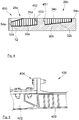
- the Fig. 4 shows a tool 450 according to a second embodiment of the invention.
- the difference between the tool 50 of the first embodiment and the tool 450 of the second embodiment lies in the fact that the contact surfaces of the two soundproofing panels 26a and 26b are not flat in the second embodiment.
- the contact surface of the soundproofing panel 26a has a housing 452 at the top and the contact surface of the soundproofing panel 26b has a projection 451 which is intended to accommodate in the housing 452 when the two soundproofing panels 26a and 26b are put in place.
- the mold 52 In order to produce the housing 452 during the production of the soundproofing panel 26a, the mold 52 includes a release key 453 which is fixed in the cavity 54a in place of the housing 452 and which is removable to allow the soundproofing panel 26a to be removed from the mold. .
- the invention is more particularly described in the context of a turbine engine, but it applies in the same way to all types of propulsion systems for an aircraft 10.
Landscapes
- Engineering & Computer Science (AREA)
- Mechanical Engineering (AREA)
- Chemical & Material Sciences (AREA)
- Combustion & Propulsion (AREA)
- Composite Materials (AREA)
- Architecture (AREA)
- Civil Engineering (AREA)
- Structural Engineering (AREA)
- Manufacturing & Machinery (AREA)
- Aviation & Aerospace Engineering (AREA)
- General Engineering & Computer Science (AREA)
- Transportation (AREA)
- Casting Or Compression Moulding Of Plastics Or The Like (AREA)
- Moulding By Coating Moulds (AREA)
- Moulds For Moulding Plastics Or The Like (AREA)
- Soundproofing, Sound Blocking, And Sound Damping (AREA)
Abstract
L'invention concerne un procédé de fabrication de deux panneaux insonorisants (26a, 26b) d'une nacelle d'un aéronef comportant une veine, le procédé de fabrication comportant :- une étape de fourniture d'un moule (52) présentant sur une même face, une cavité (54a, 54b) pour chaque panneau insonorisant (26a, 26b),- une étape de réalisation dans le fond de chaque cavité (54a, 54b) d'une peau intérieure (32a, 32b) destinée à être orientée vers la veine, et- une étape de cuisson au cours de laquelle les éléments présents dans le moule (52) sont cuits dans le moule (52).Un tel procédé permet de réaliser les deux panneaux insonorisants dans le même moule réduisant ainsi les écarts entre eux après leur mise en position.
Description
- La présente invention concerne un procédé de fabrication de deux panneaux insonorisants pour un ensemble propulsif d'aéronef, ainsi qu'un moule pour la mise en oeuvre d'un tel procédé.
- Un turbomoteur d'aéronef comporte une nacelle qui présente à l'avant une structure d'entrée d'air qui est pourvue d'une lèvre qui délimite l'intérieur et l'extérieur de la nacelle. La lèvre se prolonge vers l'intérieur de la nacelle par une paroi qui est disposée autour d'une veine qui canalise l'air en direction de la motorisation comportant entre autres une soufflante.
- La paroi est équipée en particulier de panneaux insonorisants qui atténuent les bruits générés par la motorisation.
- Dans le cas de l'état de la technique, il est connu d'utiliser deux panneaux insonorisants qui sont disposés l'un derrière l'autre par rapport au sens de l'écoulement de l'air dans la veine. La
Fig. 5 montre une telle installation 400 de l'état de la technique. - Un premier panneau insonorisant 402, dit panneau acoustique, dont la partie avant est fixée au niveau de la lèvre et dont la partie arrière est fixée au niveau d'une bride de fixation 404.
- Un deuxième panneau insonorisant 406, situé juste devant les pales du turbomoteur et à l'intérieur du carter de soufflante. La partie avant du deuxième panneau insonorisant 406 est disposée à l'arrière du premier panneau insonorisant 402 et est fixée au niveau de la bride de fixation 404.
- Bien qu'une telle architecture donne de bons résultats, le fait que ces deux panneaux insonorisants soient réalisés indépendamment l'un de l'autre, entraîne l'apparition d'un décalage radial entre les deux panneaux insonorisants et donc d'une marche qui engendre des perturbations aérodynamiques et une augmentation de la traînée.
- En outre, un écart parallèlement à l'axe longitudinal du turbomoteur peut apparaître du fait de l'architecture de la liaison entre les deux panneaux insonorisants.
- Un objet de la présente invention est de proposer un procédé de fabrication de deux panneaux insonorisants pour un moteur d'aéronef qui permet d'éliminer le décalage radial et l'écart entre les deux panneaux insonorisants.
- A cet effet, est proposé un procédé de fabrication de deux panneaux insonorisants d'une nacelle d'un aéronef comportant une veine où chaque panneau insonorisant comporte une peau intérieure destinée à être orientée vers la veine, le procédé de fabrication comportant :
- une étape de fourniture d'un moule présentant sur une même face, une cavité pour chaque panneau insonorisant,
- une étape de réalisation dans le fond de chaque cavité d'une peau intérieure, et
- une étape de cuisson au cours de laquelle les éléments présents dans le moule sont cuits dans le moule.
- Un tel procédé permet de réaliser les deux panneaux insonorisants dans le même moule réduisant ainsi les écarts entre eux après leur mise en position.
- Selon un mode de réalisation particulier, entre l'étape de réalisation et l'étape de cuisson, le procédé comporte une étape de mise en place d'une âme en nid d'abeilles au-dessus de chaque peau intérieure puis une étape de mise en place au-dessus de chaque âme d'un panneau extérieur.
- Selon un mode de réalisation particulier, le procédé de fabrication comporte après l'étape de cuisson, une étape de mise en place d'une âme en nid d'abeilles au-dessus de chaque peau intérieure puis une étape de mise en place au-dessus de chaque âme d'un panneau extérieur.
- L'invention propose également un moule pour la réalisation de deux panneaux insonorisants d'une nacelle d'un aéronef comportant une veine où chaque panneau insonorisant comporte une peau intérieure destinée à être orientée vers la veine, où le moule présente sur une même face, une cavité pour chaque panneau insonorisant, où le fond de chaque cavité matérialise la surface de la peau intérieure.
- Les caractéristiques de l'invention mentionnées ci-dessus, ainsi que d'autres, apparaîtront plus clairement à la lecture de la description suivante d'un exemple de réalisation, ladite description étant faite en relation avec les dessins joints, parmi lesquels :
- la
Fig. 1 représente une vue de côté d'un aéronef selon l'invention, - la
Fig. 2 est une vue de côté et en coupe d'un détail d'un turbomoteur selon l'invention, - la
Fig. 3 est une représentation schématique d'un outillage permettant la mise en oeuvre d'un procédé de fabrication selon un premier mode de réalisation de l'invention, - la
Fig. 4 est une représentation schématique d'un outillage permettant la mise en oeuvre d'un procédé de fabrication selon un deuxième mode de réalisation de l'invention, et - la
Fig. 5 montre une vue de côté de panneaux insonorisants selon l'état de la technique. - Dans la description qui suit, les termes relatifs à une position sont pris en référence à un aéronef en position d'avancement, c'est-à-dire comme il est représenté sur la
Fig. 1 . - La
Fig. 1 montre un aéronef 10 qui comporte au moins un turbomoteur 20. - Dans toute la description qui va suivre, par convention, la direction X correspond à la direction longitudinale du turbomoteur 20, cette direction étant parallèle à l'axe longitudinal X du turbomoteur 20. D'autre part, la direction Y correspond à la direction orientée transversalement par rapport au turbomoteur 20, et la direction Z correspond à la direction verticale ou hauteur, ces trois directions X, Y, Z étant orthogonales entre elles.
- Le turbomoteur 20 comporte classiquement une nacelle 19 qui comporte une structure d'entrée d'air 22 comportant une structure interne 24 (
Fig. 2 ). - La
Fig. 2 montre une coupe de la structure interne 24 qui permet un traitement acoustique. La structure interne 24 est disposée autour d'une veine 38 qui canalise l'air vers une motorisation qui comporte entre autres une soufflante. - La structure interne 24 comporte successivement deux panneaux insonorisants 26a et 26b qui sont fixés à une structure 28a, 28b de la nacelle 19. La fixation des deux panneaux insonorisants 26a et 26b n'est pas décrite plus précisément et reprend par exemple les mêmes éléments que pour un turbomoteur de l'état de la technique.
- Chaque panneau insonorisant 26a, 26b prend la forme d'une structure multicouche qui présente une âme en nid d'abeilles 30a, 30b qui est fixée entre une peau intérieure 32a, 32b orientée vers la veine 38 et un panneau extérieur 34a, 34b orienté à l'opposé. Chaque panneau insonorisant 26a, 26b présente une surface de contact qui est en contact avec la surface de contact de l'autre panneau insonorisant 26b, 26a.
- Chaque peau intérieure 32a, 32b est poreuse permettant aux ondes sonores de se propager dans l'âme 30a, 30b pour y être atténuées. La porosité est réalisée par exemple par des trous (non représentés) traversant chaque peau intérieure 32a, 32b.
- La
Fig. 3 montre un outillage 50 selon un premier mode de réalisation de l'invention et qui comporte un moule 52 présentant sur une même face, une cavité 54a, 54b pour chaque panneau insonorisant 26a, 26b. Chaque cavité 54a, 54b est ouverte sur la même face. - Le fond de chaque cavité 54a, 54b est conformé pour mouler la peau intérieure 32a, 32b du panneau insonorisant 26a, 26b associé. Ainsi, les deux peaux intérieures 32a, 32b des deux panneaux insonorisants 26a, 26b sont réalisées dans le même moule 52 ce qui évite les cumuls de tolérances lorsque des moules différents sont utilisés. En effet, les deux cavités 54a et 54b sont usinées au cours d'un même processus par une même machine qui peut garder la même référence tout le long de l'usinage. Après montage des deux panneaux insonorisants 26a et 26b, les écarts entre eux sont réduits par rapport à ceux des panneaux insonorisants de l'état de la technique. En outre, l'utilisation d'un même moule 52 permet de suivre le même cycle de cuisson pour les deux panneaux insonorisants 26a, 26b.
- Pour chaque cavité 54a, 54b, le fond de la cavité 54a, 54b matérialise la surface de la peau intérieure 32a, 32b, la surface étant celle qui est orientée vers la veine 38.
- La réalisation de chaque peau intérieure 32a, 32b s'effectue classiquement par la dépose, dans le fond de la cavité 54a, 54b, de couches de matériaux, en particulier composites, qui sont ainsi moulées dans les cavités 54a, 54b.
- L'âme 30a, 30b est ensuite déposée sur la peau intérieure 32a, 32b correspondante, et chaque panneau extérieur 34a, 34b est ensuite déposé sur l'âme 30a, 30b associée.
- Chaque ensemble ainsi réalisé est ensuite cuit pour prendre sa forme définitive. L'étape de cuisson s'effectue préférentiellement sous vide d'air qui est réalisé par un circuit de vide commun aux deux cavités 54a, 54b. La réalisation du vide s'effectue par exemple par mise en place d'un contre-moule qui vient obturer les deux cavités 54a, 54b.
- Selon un autre mode de réalisation, les peaux intérieures 32a, 32b sont cuites simultanément dans le moule 52, tandis que les âmes 30a, 30b et les panneaux extérieurs 34a, 34b sont cuits indépendamment et fixés postérieurement.
- Le procédé de fabrication selon l'invention des deux panneaux insonorisants 26a et 26b comporte :
- une étape de fourniture au cours de laquelle le moule 52 présentant une cavité 54a, 54b pour chaque panneau insonorisant 26a, 26b est fourni,
- une étape de réalisation au cours de laquelle, dans le fond de chaque cavité 54a, 54b, une peau intérieure 32a, 32b est réalisée, et
- une étape de cuisson au cours de laquelle les éléments présents dans le moule 52 sont cuits dans le moule 52.
- Selon le mode de réalisation mis en oeuvre, les éléments qui subissent l'étape de cuisson sont les peaux intérieures 32a, 32b, les âmes 30a, 30b et les panneaux extérieurs 34a, 34b ou uniquement les peaux intérieures 32a, 32b.
- Selon un mode de réalisation particulier, entre l'étape de réalisation et l'étape de cuisson, le procédé comporte une étape de mise en place d'une âme en nid d'abeilles 30a, 30b au-dessus de chaque peau intérieure 32a, 32b puis une étape de mise en place au-dessus de chaque âme 30a, 30b d'un panneau extérieur 34a, 34b. Les âmes 30a, 30b et les panneaux extérieurs 34a, 34b sont ainsi fixés avant cuisson.
- Selon un autre mode de réalisation particulier, le procédé comporte après l'étape de cuisson, une étape de mise en place d'une âme en nid d'abeilles 30a, 30b au-dessus de chaque peau intérieure 32a, 32b puis une étape de mise en place au-dessus de chaque âme 30a, 30b d'un panneau extérieur 34a, 34b. Les âmes 30a, 30b et les panneaux extérieurs 34a, 34b sont ainsi fixés après cuisson.
- Le perçage de chaque peau intérieure 32a, 32b peut s'effectuer avant ou après la fabrication du panneau insonorisant 26a, 26b.
- La
Fig. 4 montre un outillage 450 selon un deuxième mode de réalisation de l'invention. La différence entre l'outillage 50 du premier mode de réalisation et l'outillage 450 du deuxième mode de réalisation réside dans le fait que les surfaces de contact des deux panneaux insonorisants 26a et 26b ne sont pas planes dans le deuxième mode de réalisation. - Ainsi, dans le mode de réalisation de la
Fig. 4 , la surface de contact du panneau insonorisant 26a présente un logement 452 en partie haute et la surface de contact du panneau insonorisant 26b présente une excroissance 451 qui est prévue pour loger dans le logement 452 lorsque les deux panneaux insonorisants 26a et 26b sont mis en place. - Afin de réaliser le logement 452 lors de la réalisation du panneau insonorisant 26a, le moule 52 comporte une clé de démoulage 453 qui est fixée dans la cavité 54a en lieu et place du logement 452 et qui est amovible pour permettre le démoulage du panneau insonorisant 26a.
- L'invention est plus particulièrement décrite dans le cadre d'un turbomoteur, mais elle s'applique de la même manière à tous types d'ensembles propulsifs pour un aéronef 10.
Claims (4)
- Procédé de fabrication de deux panneaux insonorisants (26a, 26b) d'une nacelle (19) d'un aéronef (10) comportant une veine (38) où chaque panneau insonorisant (26a, 26b) comporte une peau intérieure (32a, 32b) destinée à être orientée vers la veine (38), le procédé de fabrication comportant :- une étape de fourniture d'un moule (52) présentant sur une même face, une cavité (54a, 54b) pour chaque panneau insonorisant (26a, 26b),- une étape de réalisation dans le fond de chaque cavité (54a, 54b) d'une peau intérieure (32a, 32b), et- une étape de cuisson au cours de laquelle les éléments présents dans le moule (52) sont cuits dans le moule (52).
- Procédé de fabrication selon la revendication 1, caractérisé en ce qu'entre l'étape de réalisation et l'étape de cuisson, le procédé comporte une étape de mise en place d'une âme en nid d'abeilles (30a, 30b) au-dessus de chaque peau intérieure (32a, 32b) puis une étape de mise en place au-dessus de chaque âme (30a, 30b) d'un panneau extérieur (34a, 34b).
- Procédé de fabrication selon la revendication 1, caractérisé en ce qu'il comporte après l'étape de cuisson, une étape de mise en place d'une âme en nid d'abeilles (30a, 30b) au-dessus de chaque peau intérieure (32a, 32b) puis une étape de mise en place au-dessus de chaque âme (30a, 30b) d'un panneau extérieur (34a, 34b).
- Moule (52) pour la réalisation de deux panneaux insonorisants (26a, 26b) d'une nacelle (19) d'un aéronef (10) comportant une veine (38) où chaque panneau insonorisant (26a, 26b) comporte une peau intérieure (32a, 32b) destinée à être orientée vers la veine (38), où le moule (52) présente sur une même face, une cavité (54a, 54b) pour chaque panneau insonorisant (26a, 26b), où le fond de chaque cavité (54a, 54b) matérialise la surface de la peau intérieure (32a, 32b).
Applications Claiming Priority (1)
| Application Number | Priority Date | Filing Date | Title |
|---|---|---|---|
| FR1858999A FR3086698B1 (fr) | 2018-09-28 | 2018-09-28 | Procede de fabrication de deux panneaux insonorisants dans un meme moule |
Publications (1)
| Publication Number | Publication Date |
|---|---|
| EP3628461A1 true EP3628461A1 (fr) | 2020-04-01 |
Family
ID=65244005
Family Applications (1)
| Application Number | Title | Priority Date | Filing Date |
|---|---|---|---|
| EP19198932.6A Withdrawn EP3628461A1 (fr) | 2018-09-28 | 2019-09-23 | Procede de fabrication de deux panneaux insonorisants dans un même moule et moule por la réalisation de deux paneaux insonorisants |
Country Status (4)
| Country | Link |
|---|---|
| US (1) | US11731381B2 (fr) |
| EP (1) | EP3628461A1 (fr) |
| CN (1) | CN110962257A (fr) |
| FR (1) | FR3086698B1 (fr) |
Citations (2)
| Publication number | Priority date | Publication date | Assignee | Title |
|---|---|---|---|---|
| JP2002321238A (ja) * | 2001-04-26 | 2002-11-05 | Kawasaki Heavy Ind Ltd | 航空機エンジンナセル吸音パネル用多孔板の製造方法 |
| US20100080980A1 (en) * | 2008-09-30 | 2010-04-01 | Mra Systems, Inc. | Molding process for core-containing composites and composites formed thereby |
Family Cites Families (11)
| Publication number | Priority date | Publication date | Assignee | Title |
|---|---|---|---|---|
| JP3855083B2 (ja) * | 2004-04-30 | 2006-12-06 | 株式会社日本製鋼所 | 中空成形品の成形方法および製造装置 |
| FR2928415B1 (fr) * | 2008-03-07 | 2010-12-03 | Aircelle Sa | Panneau acoustique d'une nacelle d'un aeronef |
| US8128775B2 (en) * | 2008-12-30 | 2012-03-06 | Mra Systems, Inc. | Process and apparatus for producing composite structures |
| FR2963469B1 (fr) * | 2010-07-27 | 2012-07-27 | Aircelle Sa | Panneau acoustique |
| FR2975943B1 (fr) * | 2011-06-01 | 2013-05-17 | Aircelle Sa | Procede de fabrication d'un panneau d'attenuation acoustique |
| FR2985682B1 (fr) * | 2012-01-18 | 2016-05-06 | Aircelle Sa | Ensemble d'outillage et procede de fabrication d’une piece en materiau composite |
| FR2989310B1 (fr) * | 2012-04-11 | 2014-04-04 | Aircelle Sa | Procede de fabrication d'un panneau sandwich composite a ame alveolaire |
| US9352822B2 (en) * | 2012-05-30 | 2016-05-31 | The Boeing Company | Bonded composite airfoil |
| KR102068312B1 (ko) * | 2013-10-18 | 2020-01-20 | 에스케이이노베이션 주식회사 | 활성화된 eu-2 제올라이트 및 이의 용도 |
| US10800117B2 (en) * | 2015-03-12 | 2020-10-13 | Rohr, Inc. | Method of forming an acoustic bond panel with insertable acoustic assemblies |
| FR3039147B1 (fr) * | 2015-07-24 | 2017-08-25 | Aircelle Sa | Panneau d’attenuation acoustique en materiau composite ceramique oxyde avec ame en materiau metallique converti electrochimiquement |
-
2018
- 2018-09-28 FR FR1858999A patent/FR3086698B1/fr active Active
-
2019
- 2019-09-23 EP EP19198932.6A patent/EP3628461A1/fr not_active Withdrawn
- 2019-09-24 US US16/580,942 patent/US11731381B2/en active Active
- 2019-09-29 CN CN201910932619.9A patent/CN110962257A/zh active Pending
Patent Citations (2)
| Publication number | Priority date | Publication date | Assignee | Title |
|---|---|---|---|---|
| JP2002321238A (ja) * | 2001-04-26 | 2002-11-05 | Kawasaki Heavy Ind Ltd | 航空機エンジンナセル吸音パネル用多孔板の製造方法 |
| US20100080980A1 (en) * | 2008-09-30 | 2010-04-01 | Mra Systems, Inc. | Molding process for core-containing composites and composites formed thereby |
Also Published As
| Publication number | Publication date |
|---|---|
| US11731381B2 (en) | 2023-08-22 |
| FR3086698B1 (fr) | 2021-01-22 |
| FR3086698A1 (fr) | 2020-04-03 |
| US20200101643A1 (en) | 2020-04-02 |
| CN110962257A (zh) | 2020-04-07 |
Similar Documents
| Publication | Publication Date | Title |
|---|---|---|
| EP3814622B1 (fr) | Panneau d'atténuation acoustique pour nacelle de turboréacteur d'aéronef | |
| EP3959135B1 (fr) | Entrée d'air de nacelle de turboréacteur | |
| CA3075234A1 (fr) | Procede de fabrication d'une ame alveolaire pour panneau acoustique | |
| EP3779961A1 (fr) | Elément acoustique à double enceinte et encombrement réduit, en particulier pour panneau acoustique d'aéronef | |
| EP3674530B1 (fr) | Procédé de fabrication d'une structure d'absorption acoustique comprenant un panneau alvéolaire intégrant des éléments acoustiques et structure d' absorption acoustique obtenue à partir dudit procédé | |
| EP3839238B1 (fr) | Cône de sortie d'un ensemble propulsif d'aéronef formant un système de traitement acoustique à au moins deux degrés de liberté | |
| EP3959138B1 (fr) | Entrée d'air de nacelle et nacelle comportant une telle entrée d'air | |
| FR3120732A1 (fr) | Procédé de fabrication d’une structure d’absorption acoustique, structure d’absorption acoustique ainsi obtenue | |
| FR3037974A1 (fr) | Procede de fabrication d'une aube comportant une baignoire integrant un muret | |
| EP3538752A1 (fr) | Panneau d'atténuation acoustique comprenant une peau avant et une structure centrale | |
| FR3055612A1 (fr) | Structure compartimentee pour le traitement acoustique et le degivrage d'une nacelle d'aeronef et nacelle d'aeronef incorporant ladite structure | |
| EP3628461A1 (fr) | Procede de fabrication de deux panneaux insonorisants dans un même moule et moule por la réalisation de deux paneaux insonorisants | |
| FR3027843A1 (fr) | Procede pour la reparation d'une peau perforee d'un panneau au moyen d'un doubleur | |
| FR3100917A1 (fr) | Panneau acoustique pour un ensemble propulsif d’aeronef, et son procede de fabrication | |
| EP2435685B1 (fr) | Turbomoteur comportant un cone de guidage des gaz d'echappement avec un attenuateur sonore | |
| EP3959134B1 (fr) | Entrée d'air de nacelle à panneau acoustique | |
| WO2023198715A1 (fr) | Élement de structure muni d'inserts rapportés pour une structure composite acoustique et procédé de fabrication associé | |
| WO2016092238A1 (fr) | Procédé pour la réparation d'un panneau acoustique en matériau composite | |
| EP3853465A1 (fr) | Gestion acoustique, sur une turbomachine ou une nacelle | |
| FR3144936A1 (fr) | Procédé de fabrication amélioré d’un complexe acoustique par fabrication additive et complexe acoustique obtenu par un tel procédé | |
| FR3105553A1 (fr) | Système de traitement acoustique à au moins deux degrés de liberté comportant un revêtement quart d’onde permettant le passage d’ondes acoustiques dans un résonateur à mode de cavité | |
| FR3166327A1 (fr) | Panneau sandwich acoustique a montage ameliore | |
| EP4482738A1 (fr) | Dispositif d'absorption acoustique | |
| EP4685787A1 (fr) | Structure d'absorption acoustique comprenant un système de cloisonnement pourvu d'au moins un pied |
Legal Events
| Date | Code | Title | Description |
|---|---|---|---|
| PUAI | Public reference made under article 153(3) epc to a published international application that has entered the european phase |
Free format text: ORIGINAL CODE: 0009012 |
|
| STAA | Information on the status of an ep patent application or granted ep patent |
Free format text: STATUS: THE APPLICATION HAS BEEN PUBLISHED |
|
| AK | Designated contracting states |
Kind code of ref document: A1 Designated state(s): AL AT BE BG CH CY CZ DE DK EE ES FI FR GB GR HR HU IE IS IT LI LT LU LV MC MK MT NL NO PL PT RO RS SE SI SK SM TR |
|
| AX | Request for extension of the european patent |
Extension state: BA ME |
|
| 18D | Application deemed to be withdrawn |
Effective date: 20201002 |