EP3627614B1 - Battery pack - Google Patents
Battery pack Download PDFInfo
- Publication number
- EP3627614B1 EP3627614B1 EP18884646.3A EP18884646A EP3627614B1 EP 3627614 B1 EP3627614 B1 EP 3627614B1 EP 18884646 A EP18884646 A EP 18884646A EP 3627614 B1 EP3627614 B1 EP 3627614B1
- Authority
- EP
- European Patent Office
- Prior art keywords
- contactor
- charging
- measurement
- control unit
- battery
- Prior art date
- Legal status (The legal status is an assumption and is not a legal conclusion. Google has not performed a legal analysis and makes no representation as to the accuracy of the status listed.)
- Active
Links
- 238000005259 measurement Methods 0.000 claims description 110
- 238000005286 illumination Methods 0.000 description 29
- 238000010586 diagram Methods 0.000 description 10
- 230000006870 function Effects 0.000 description 5
- PXHVJJICTQNCMI-UHFFFAOYSA-N Nickel Chemical compound [Ni] PXHVJJICTQNCMI-UHFFFAOYSA-N 0.000 description 4
- 238000003745 diagnosis Methods 0.000 description 4
- 238000000034 method Methods 0.000 description 4
- 238000012986 modification Methods 0.000 description 4
- 230000004048 modification Effects 0.000 description 4
- 230000008569 process Effects 0.000 description 3
- WHXSMMKQMYFTQS-UHFFFAOYSA-N Lithium Chemical compound [Li] WHXSMMKQMYFTQS-UHFFFAOYSA-N 0.000 description 2
- 238000007599 discharging Methods 0.000 description 2
- 230000000694 effects Effects 0.000 description 2
- 229910052744 lithium Inorganic materials 0.000 description 2
- 229910052759 nickel Inorganic materials 0.000 description 2
- 239000004065 semiconductor Substances 0.000 description 2
- UFHFLCQGNIYNRP-UHFFFAOYSA-N Hydrogen Chemical compound [H][H] UFHFLCQGNIYNRP-UHFFFAOYSA-N 0.000 description 1
- OJIJEKBXJYRIBZ-UHFFFAOYSA-N cadmium nickel Chemical compound [Ni].[Cd] OJIJEKBXJYRIBZ-UHFFFAOYSA-N 0.000 description 1
- 238000004891 communication Methods 0.000 description 1
- 238000013461 design Methods 0.000 description 1
- 238000001514 detection method Methods 0.000 description 1
- 238000004146 energy storage Methods 0.000 description 1
- 229910052739 hydrogen Inorganic materials 0.000 description 1
- 239000001257 hydrogen Substances 0.000 description 1
- 230000003446 memory effect Effects 0.000 description 1
- QELJHCBNGDEXLD-UHFFFAOYSA-N nickel zinc Chemical compound [Ni].[Zn] QELJHCBNGDEXLD-UHFFFAOYSA-N 0.000 description 1
- 230000003287 optical effect Effects 0.000 description 1
- 230000001151 other effect Effects 0.000 description 1
- 238000012545 processing Methods 0.000 description 1
- 230000004044 response Effects 0.000 description 1
- 238000006467 substitution reaction Methods 0.000 description 1
- 238000003466 welding Methods 0.000 description 1
Images


Classifications
-
- H—ELECTRICITY
- H02—GENERATION; CONVERSION OR DISTRIBUTION OF ELECTRIC POWER
- H02J—CIRCUIT ARRANGEMENTS OR SYSTEMS FOR SUPPLYING OR DISTRIBUTING ELECTRIC POWER; SYSTEMS FOR STORING ELECTRIC ENERGY
- H02J7/00—Circuit arrangements for charging or depolarising batteries or for supplying loads from batteries
- H02J7/0029—Circuit arrangements for charging or depolarising batteries or for supplying loads from batteries with safety or protection devices or circuits
- H02J7/0036—Circuit arrangements for charging or depolarising batteries or for supplying loads from batteries with safety or protection devices or circuits using connection detecting circuits
-
- H—ELECTRICITY
- H02—GENERATION; CONVERSION OR DISTRIBUTION OF ELECTRIC POWER
- H02J—CIRCUIT ARRANGEMENTS OR SYSTEMS FOR SUPPLYING OR DISTRIBUTING ELECTRIC POWER; SYSTEMS FOR STORING ELECTRIC ENERGY
- H02J7/00—Circuit arrangements for charging or depolarising batteries or for supplying loads from batteries
- H02J7/00032—Circuit arrangements for charging or depolarising batteries or for supplying loads from batteries characterised by data exchange
- H02J7/00038—Circuit arrangements for charging or depolarising batteries or for supplying loads from batteries characterised by data exchange using passive battery identification means, e.g. resistors or capacitors
- H02J7/00041—Circuit arrangements for charging or depolarising batteries or for supplying loads from batteries characterised by data exchange using passive battery identification means, e.g. resistors or capacitors in response to measured battery parameters, e.g. voltage, current or temperature profile
-
- H—ELECTRICITY
- H01—ELECTRIC ELEMENTS
- H01M—PROCESSES OR MEANS, e.g. BATTERIES, FOR THE DIRECT CONVERSION OF CHEMICAL ENERGY INTO ELECTRICAL ENERGY
- H01M10/00—Secondary cells; Manufacture thereof
- H01M10/42—Methods or arrangements for servicing or maintenance of secondary cells or secondary half-cells
- H01M10/425—Structural combination with electronic components, e.g. electronic circuits integrated to the outside of the casing
- H01M10/4257—Smart batteries, e.g. electronic circuits inside the housing of the cells or batteries
-
- G—PHYSICS
- G01—MEASURING; TESTING
- G01R—MEASURING ELECTRIC VARIABLES; MEASURING MAGNETIC VARIABLES
- G01R31/00—Arrangements for testing electric properties; Arrangements for locating electric faults; Arrangements for electrical testing characterised by what is being tested not provided for elsewhere
- G01R31/005—Testing of electric installations on transport means
- G01R31/006—Testing of electric installations on transport means on road vehicles, e.g. automobiles or trucks
-
- G—PHYSICS
- G01—MEASURING; TESTING
- G01R—MEASURING ELECTRIC VARIABLES; MEASURING MAGNETIC VARIABLES
- G01R31/00—Arrangements for testing electric properties; Arrangements for locating electric faults; Arrangements for electrical testing characterised by what is being tested not provided for elsewhere
- G01R31/327—Testing of circuit interrupters, switches or circuit-breakers
-
- H—ELECTRICITY
- H01—ELECTRIC ELEMENTS
- H01M—PROCESSES OR MEANS, e.g. BATTERIES, FOR THE DIRECT CONVERSION OF CHEMICAL ENERGY INTO ELECTRICAL ENERGY
- H01M10/00—Secondary cells; Manufacture thereof
- H01M10/42—Methods or arrangements for servicing or maintenance of secondary cells or secondary half-cells
- H01M10/46—Accumulators structurally combined with charging apparatus
-
- H—ELECTRICITY
- H01—ELECTRIC ELEMENTS
- H01M—PROCESSES OR MEANS, e.g. BATTERIES, FOR THE DIRECT CONVERSION OF CHEMICAL ENERGY INTO ELECTRICAL ENERGY
- H01M10/00—Secondary cells; Manufacture thereof
- H01M10/42—Methods or arrangements for servicing or maintenance of secondary cells or secondary half-cells
- H01M10/48—Accumulators combined with arrangements for measuring, testing or indicating the condition of cells, e.g. the level or density of the electrolyte
-
- H—ELECTRICITY
- H01—ELECTRIC ELEMENTS
- H01M—PROCESSES OR MEANS, e.g. BATTERIES, FOR THE DIRECT CONVERSION OF CHEMICAL ENERGY INTO ELECTRICAL ENERGY
- H01M50/00—Constructional details or processes of manufacture of the non-active parts of electrochemical cells other than fuel cells, e.g. hybrid cells
- H01M50/20—Mountings; Secondary casings or frames; Racks, modules or packs; Suspension devices; Shock absorbers; Transport or carrying devices; Holders
- H01M50/204—Racks, modules or packs for multiple batteries or multiple cells
-
- H—ELECTRICITY
- H01—ELECTRIC ELEMENTS
- H01M—PROCESSES OR MEANS, e.g. BATTERIES, FOR THE DIRECT CONVERSION OF CHEMICAL ENERGY INTO ELECTRICAL ENERGY
- H01M50/00—Constructional details or processes of manufacture of the non-active parts of electrochemical cells other than fuel cells, e.g. hybrid cells
- H01M50/20—Mountings; Secondary casings or frames; Racks, modules or packs; Suspension devices; Shock absorbers; Transport or carrying devices; Holders
- H01M50/249—Mountings; Secondary casings or frames; Racks, modules or packs; Suspension devices; Shock absorbers; Transport or carrying devices; Holders specially adapted for aircraft or vehicles, e.g. cars or trains
-
- H—ELECTRICITY
- H01—ELECTRIC ELEMENTS
- H01M—PROCESSES OR MEANS, e.g. BATTERIES, FOR THE DIRECT CONVERSION OF CHEMICAL ENERGY INTO ELECTRICAL ENERGY
- H01M50/00—Constructional details or processes of manufacture of the non-active parts of electrochemical cells other than fuel cells, e.g. hybrid cells
- H01M50/20—Mountings; Secondary casings or frames; Racks, modules or packs; Suspension devices; Shock absorbers; Transport or carrying devices; Holders
- H01M50/296—Mountings; Secondary casings or frames; Racks, modules or packs; Suspension devices; Shock absorbers; Transport or carrying devices; Holders characterised by terminals of battery packs
-
- H—ELECTRICITY
- H01—ELECTRIC ELEMENTS
- H01M—PROCESSES OR MEANS, e.g. BATTERIES, FOR THE DIRECT CONVERSION OF CHEMICAL ENERGY INTO ELECTRICAL ENERGY
- H01M50/00—Constructional details or processes of manufacture of the non-active parts of electrochemical cells other than fuel cells, e.g. hybrid cells
- H01M50/50—Current conducting connections for cells or batteries
- H01M50/569—Constructional details of current conducting connections for detecting conditions inside cells or batteries, e.g. details of voltage sensing terminals
-
- H—ELECTRICITY
- H02—GENERATION; CONVERSION OR DISTRIBUTION OF ELECTRIC POWER
- H02J—CIRCUIT ARRANGEMENTS OR SYSTEMS FOR SUPPLYING OR DISTRIBUTING ELECTRIC POWER; SYSTEMS FOR STORING ELECTRIC ENERGY
- H02J7/00—Circuit arrangements for charging or depolarising batteries or for supplying loads from batteries
- H02J7/14—Circuit arrangements for charging or depolarising batteries or for supplying loads from batteries for charging batteries from dynamo-electric generators driven at varying speed, e.g. on vehicle
- H02J7/1407—Circuit arrangements for charging or depolarising batteries or for supplying loads from batteries for charging batteries from dynamo-electric generators driven at varying speed, e.g. on vehicle on vehicles not being driven by a motor, e.g. bicycles
-
- H—ELECTRICITY
- H01—ELECTRIC ELEMENTS
- H01M—PROCESSES OR MEANS, e.g. BATTERIES, FOR THE DIRECT CONVERSION OF CHEMICAL ENERGY INTO ELECTRICAL ENERGY
- H01M10/00—Secondary cells; Manufacture thereof
- H01M10/42—Methods or arrangements for servicing or maintenance of secondary cells or secondary half-cells
- H01M10/425—Structural combination with electronic components, e.g. electronic circuits integrated to the outside of the casing
- H01M2010/4271—Battery management systems including electronic circuits, e.g. control of current or voltage to keep battery in healthy state, cell balancing
-
- H—ELECTRICITY
- H01—ELECTRIC ELEMENTS
- H01M—PROCESSES OR MEANS, e.g. BATTERIES, FOR THE DIRECT CONVERSION OF CHEMICAL ENERGY INTO ELECTRICAL ENERGY
- H01M2220/00—Batteries for particular applications
- H01M2220/20—Batteries in motive systems, e.g. vehicle, ship, plane
-
- H—ELECTRICITY
- H02—GENERATION; CONVERSION OR DISTRIBUTION OF ELECTRIC POWER
- H02J—CIRCUIT ARRANGEMENTS OR SYSTEMS FOR SUPPLYING OR DISTRIBUTING ELECTRIC POWER; SYSTEMS FOR STORING ELECTRIC ENERGY
- H02J2207/00—Indexing scheme relating to details of circuit arrangements for charging or depolarising batteries or for supplying loads from batteries
- H02J2207/10—Control circuit supply, e.g. means for supplying power to the control circuit
-
- Y—GENERAL TAGGING OF NEW TECHNOLOGICAL DEVELOPMENTS; GENERAL TAGGING OF CROSS-SECTIONAL TECHNOLOGIES SPANNING OVER SEVERAL SECTIONS OF THE IPC; TECHNICAL SUBJECTS COVERED BY FORMER USPC CROSS-REFERENCE ART COLLECTIONS [XRACs] AND DIGESTS
- Y02—TECHNOLOGIES OR APPLICATIONS FOR MITIGATION OR ADAPTATION AGAINST CLIMATE CHANGE
- Y02E—REDUCTION OF GREENHOUSE GAS [GHG] EMISSIONS, RELATED TO ENERGY GENERATION, TRANSMISSION OR DISTRIBUTION
- Y02E60/00—Enabling technologies; Technologies with a potential or indirect contribution to GHG emissions mitigation
- Y02E60/10—Energy storage using batteries
-
- Y—GENERAL TAGGING OF NEW TECHNOLOGICAL DEVELOPMENTS; GENERAL TAGGING OF CROSS-SECTIONAL TECHNOLOGIES SPANNING OVER SEVERAL SECTIONS OF THE IPC; TECHNICAL SUBJECTS COVERED BY FORMER USPC CROSS-REFERENCE ART COLLECTIONS [XRACs] AND DIGESTS
- Y02—TECHNOLOGIES OR APPLICATIONS FOR MITIGATION OR ADAPTATION AGAINST CLIMATE CHANGE
- Y02T—CLIMATE CHANGE MITIGATION TECHNOLOGIES RELATED TO TRANSPORTATION
- Y02T10/00—Road transport of goods or passengers
- Y02T10/60—Other road transportation technologies with climate change mitigation effect
- Y02T10/70—Energy storage systems for electromobility, e.g. batteries
-
- Y—GENERAL TAGGING OF NEW TECHNOLOGICAL DEVELOPMENTS; GENERAL TAGGING OF CROSS-SECTIONAL TECHNOLOGIES SPANNING OVER SEVERAL SECTIONS OF THE IPC; TECHNICAL SUBJECTS COVERED BY FORMER USPC CROSS-REFERENCE ART COLLECTIONS [XRACs] AND DIGESTS
- Y02—TECHNOLOGIES OR APPLICATIONS FOR MITIGATION OR ADAPTATION AGAINST CLIMATE CHANGE
- Y02T—CLIMATE CHANGE MITIGATION TECHNOLOGIES RELATED TO TRANSPORTATION
- Y02T10/00—Road transport of goods or passengers
- Y02T10/60—Other road transportation technologies with climate change mitigation effect
- Y02T10/7072—Electromobility specific charging systems or methods for batteries, ultracapacitors, supercapacitors or double-layer capacitors
-
- Y—GENERAL TAGGING OF NEW TECHNOLOGICAL DEVELOPMENTS; GENERAL TAGGING OF CROSS-SECTIONAL TECHNOLOGIES SPANNING OVER SEVERAL SECTIONS OF THE IPC; TECHNICAL SUBJECTS COVERED BY FORMER USPC CROSS-REFERENCE ART COLLECTIONS [XRACs] AND DIGESTS
- Y02—TECHNOLOGIES OR APPLICATIONS FOR MITIGATION OR ADAPTATION AGAINST CLIMATE CHANGE
- Y02T—CLIMATE CHANGE MITIGATION TECHNOLOGIES RELATED TO TRANSPORTATION
- Y02T90/00—Enabling technologies or technologies with a potential or indirect contribution to GHG emissions mitigation
- Y02T90/10—Technologies relating to charging of electric vehicles
- Y02T90/14—Plug-in electric vehicles
Definitions
- the present disclosure relates to a battery pack, and more particularly, to a battery pack for diagnosing a fault of a charging contactor based on a voltage applied to a measurement resistor connected to the charging contactor.
- Secondary batteries commercially available at the present include nickel-cadmium batteries, nickel hydrogen batteries, nickel-zinc batteries, lithium secondary batteries and the like.
- the lithium secondary batteries are in the limelight since they have almost no memory effect compared to nickel-based secondary batteries and also have very low self-discharging rate and high energy density.
- the battery pack includes a battery module in which a plurality of battery cells are electrically connected, thereby meeting a high-capacity and high-power design required for an electric vehicle.
- the battery pack applied to an electric vehicle may be electrically connected to a charger of a charging station to charge the electric power.
- the battery pack applied to an electric vehicle may include a battery contactor connected to a positive electrode terminal and a negative electrode terminal of the battery module to control the electrical connection of the output terminals of the battery module, and a charging contactor for controlling the electrical connection between the battery contactor and a charging terminal to which the power of the charger is input.
- the charging contactor is exposed to the outside and also controls the electrical connection of an input terminal connected to a power connector of the charger in order to monitor whether the charging contactor is currently in a turn-on state or a turn-off state and to diagnose whether the charging contactor is actually controlled in response to the control to the turn-on state or the turn-off state.
- Such diagnostic systems for the detection of welding faults in switch contacts are disclosed for example in DE 10 2011 004516 A1 .
- the present disclosure is directed to providing a battery pack, which may diagnose a fault of each of a first charging contactor and a second charging contactor based on a first measured voltage, a second measured voltage and a third measured voltage of a first measurement resistor, a second measurement resistor and a third measurement resistor electrically connected to the first charging contactor and the second charging contactor, when a first power connector of the battery pack and a second power connector of the charger are connected and charging is being performed.
- control unit refers to a unit that processes at least one function or operation, and may be implemented by hardware, software, or a combination of hardware and software.
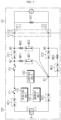
- FIGS. 1 and 2 are diagrams showing a functional configuration of the battery pack 100 according to embodiments of the present disclosure and a charger CS.
- the battery pack 100 includes a battery module B, a first battery contactor BC1, a second battery contactor BC2, a first charging contactor CC1, a second charging contactor CC2, a first measurement resistor MR1, a second measurement resistor MR2, a third measurement resistor MR3, a first power connector C1, a sensing unit 110, a memory unit 120 and a control unit 130.
- the battery module B may include at least one battery cell. If the battery module B includes a plurality of battery cells electrically connected, the plurality of battery cells may be connected to each other in series, in parallel or in series and parallel.
- the battery module B has a positive electrode terminal (+) and a negative electrode terminal (-).
- One end of the first battery contactor BC1 is electrically connected to the positive electrode terminal (+) of the battery module B, and one end of the second battery contactor BC2 is electrically connected to the negative electrode terminal (-) of the battery module B.
- the battery module B may output power or be charged according to a turn-on state or a turn-off state of the first battery contactor BC1 and the second battery contactor BC2.
- the first battery contactor BC1 and the second battery contactor BC2 may be controlled into a turn-on state or a turn-off state by the control unit 130, explained later.
- the turn-on state means a state where a contact point of the contactor is in contact to make one end and the other end of the contactor be electrically connected.
- the turn-off state means a state where the contact point of the contactor is separated to make one end and the other end of the contactor be electrically disconnected.
- One end of the first charging contactor CC1 is electrically connected to the other end of the first battery contactor BC1, and one end of the second charging contactor CC2 is electrically connected to the other end of the second battery contactor BC2.
- first charging contactor CC1 and the second charging contactor CC2 are electrically connected to the first power connector C1, respectively. More specifically, the other end of the first charging contactor CC1 is electrically connected to a first input terminal IT1 provided at the first power connector C1, and the other end of the second charging contactor CC2 is electrically connected to a second input terminal IT2 provided at the first power connector C1.
- a first output terminal OT1 and a second output terminal OT2 of the second power connector C2 may be electrically connected to the first input terminal IT1 and the second input terminal IT2, respectively.
- the first battery contactor BC1 the second battery contactor BC2
- the first charging contactor CC1 and the second charging contactor CC2 are in a turn-on state
- the second power connector C2 is connected to the first power connector C1
- the power of the charger CS is supplied to charge the battery module B.
- a second node N2 and a third node N3 are located at one end and the other end of the first charging contactor CC1, respectively, and a first node N1 and a fourth node N4 are located at one end and the other end of the second charging contactor CC2, respectively.
- the first measurement resistor MR1 is electrically connected between the first node N1 and the second node N2, and the second measurement resistor MR2 is electrically connected between the first node N1 and the third node N3. Also, the third measurement resistor MR3 is electrically connected between the first node N1 and the fourth node N4 and connected to the second charging contactor CC2 in parallel.
- the sensing unit 110 is operatively coupled to the control unit 130. That is, the sensing unit 110 may be connected to the control unit 130 to transmit an electrical signal to the control unit 130 or to receive an electrical signal from the control unit 130.
- the sensing unit 110 measures a battery voltage applied between the positive electrode terminal (+) and the negative electrode terminal (-) of the battery module B according to a preset cycle or the sensing control of the control unit 130.
- the sensing unit 110 measures a first measurement voltage, a second measurement voltage and a third measurement voltage applied to the first measurement resistor MR1, the second measurement resistor MR2 and the third measurement resistor MR3, respectively, according to the preset cycle or the sensing control of the control unit 130.
- the sensing unit 110 measures a charging voltage Vc of the charger CS applied between the first input terminal IT1 and the second input terminal IT2 or between the first output terminal OT1 and the second output terminal OT2 according to the preset cycle or the sensing control of the control unit 130.
- the sensing unit 110 repeatedly measures the battery current flowing into or out of the battery module B.
- the sensing unit 110 may provide the measured signal representing the measured battery voltage, the first measurement voltage, the second measurement voltage, the third measurement voltage, the charging voltage Vc and the battery current to the control unit 130.
- the sensing unit 110 includes a voltage sensor configured to measure the voltage of the battery module B.
- the sensing unit 110 may further include a current sensor configured to measure the current of the battery module B.
- control unit 130 may determine a digital value of each of the measured battery voltage, the first measurement voltage, the second measurement voltage, the third measurement voltage, the charging voltage Vc and the battery current, respectively, and store the digital value in the memory unit 120.
- the memory unit 120 is a semiconductor memory device that records, erases and updates data generated by the control unit 130, and stores a plurality of program codes for diagnosing faults of the first charging contactor CC1 and the second charging contactor CC2, respectively.
- the memory unit 120 may store settings used when the present disclosure is implemented.
- the memory unit 120 is not particularly limited as long as it is a semiconductor memory device known to be capable of recording, erasing and updating data.
- the memory unit 120 may be a DRAM, an SDRAM, a flash memory, a ROM, an EEPROM, a register, or the like.
- the memory unit 120 may further include a storage medium storing program codes that define the control logic of the control unit 130.
- the storage medium includes a non-volatile storage element such as a flash memory or a hard disk.
- the memory unit 120 may be physically separated from the control unit 130 or may be integrated with the control unit 130.
- the control unit 130 determines whether to perform a fault diagnosis of the first charging contactor CC1 and the second charging contactor CC2 based on a diagnosis condition.
- the diagnosis condition may include any one of whether the first power connector C1 and the second power connector C2 are coupled, whether charging is being performed, and whether the first battery contactor BC1 and the second battery contactor BC2 are in a turn-on state.
- control unit 130 determines that the diagnosis condition is satisfied if the first power connector C1 and the second power connector C2 are combined, charging is being performed, and the first battery contactor BC1 and the second battery contactor BC2 are in the turn-on state.
- the control unit 130 diagnoses whether the first charging contactor CC1 and the second charging contactor CC2 maintain the turn-on state to continue charging. More specifically, the control unit 130 diagnoses whether the first charging contactor CC 1 and the second charging contactor CC2 have a turn-on fault, respectively, and if a turn-on fault occurs in at least one of the first charging contactor CC 1 and the second charging contactor CC2, the control unit 130 diagnoses that charging is not performed.
- control unit 130 diagnoses a turn-on fault of the first charging contactor CC1 based on a measured voltage difference between the first measured voltage and the second measured voltage.
- the turn-on fault may mean a case where the contactor is controlled to turn on but is still in a turn-off state.
- the control unit 130 diagnoses that a turn-on fault occurs in the first charging contactor CC1.
- the first reference voltage may be a minimum voltage capable of identifying the measured voltage difference between the first measured voltage and the second measured voltage, which is generated due to the increase of the second measured voltage by the rise of the charging voltage Vs, when the charging voltage Vs is continuously output from the charger CS in a state where the first charging contact CC1 is in a turn-off state.
- the control unit 130 diagnoses that the first charging contactor CC1 is kept in the turn-on state.
- control unit 130 diagnoses a turn-on fault of the second charging contactor CC2 based on the third measured voltage.
- the control unit 130 diagnoses that a turn-on fault occurs in the second charging contactor CC2.
- the third measured voltage may have an absolute value.
- the second reference voltage may be a minimum voltage capable of identifying the rise of the third measured voltage, which is generated due to the increase of the voltage of the fourth node by the rise of the charging voltage Vs, when the charging voltage Vs is continuously output from the charger CS in a state where the second charging contactor CC2 is in a turn-off state.
- control unit 130 diagnoses that the second charging contactor CC2 is kept in the turn-on state.
- control unit 130 may selectively include a processor, an application-specific integrated circuit (ASIC), another chipset, a logic circuit, a register, a communication modem, a data processing device or the like in order to execute various control logics. At least one of the various control logics executable by the control unit 130 may be combined, and the combined control logic is written in a computer-readable code system and recorded on a computer-readable recording medium.
- the recording medium has no limitation as long as it can be accessed by the processor included in a computer.
- the recording medium includes at least one selected from the group consisting of a ROM, a RAM, a register, a CD-ROM, a magnetic tape, a hard disk, a floppy disk and an optical data recording device.
- a battery pack 100' according to another embodiment of the present disclosure will be described.
- some components may be further included and some components may have different functions, compared to the battery pack 100 according to the former embodiment of the present disclosure. Accordingly, the same features will not be described again.
- FIG. 3 is a diagram showing a functional configuration of the battery pack 100' according to another embodiment of the present disclosure in a state where the battery pack 100' is coupled to a charger CS
- FIG. 4 is a diagram showing a functional configuration of the battery pack 100' according to another embodiment of the present disclosure in a state where the battery pack 100' is separated from the charger CS.
- the battery pack 100' may further include a first measurement contactor MC1, a second measurement contactor MC2 and a third measurement contactor MC3, compared to the battery pack 100 according to the former embodiment of the present disclosure.
- the first measurement contactor MC1 is electrically connected between the first measurement resistor MR1 and the first node N1. More specifically, one end of the first measurement resistor MR1 is electrically connected to the second node N2, and the other end of the first measurement resistor MR1 is electrically connected to one end of the first measurement contactor MC1. Subsequently, the other end of the first measurement contactor MC1 is electrically connected to the first node N1. That is, the first measurement resistor MR1 and the first measurement contactor MC1 are electrically connected in series between the first node N1 and the second node N2.
- the second measurement contactor MC2 is electrically connected between the second measurement resistor MR2 and the first node N1. More specifically, one end of the second measurement resistor MR2 is electrically connected to the third node N3, and the other end of the second measurement resistor MR2 is electrically connected to one end of the second measurement contactor MC2. Subsequently, the other end of the second measurement contactor MC2 is electrically connected to the first node N1. That is, the second measurement resistor MR2 and the second measurement contactor MC2 are electrically connected in series between the first node N1 and the third node N3.
- the third measurement contactor MC3 is electrically connected between the third measurement resistor MR3 and the first node N1. More specifically, one end of the third measurement resistor MR3 is electrically connected to the fourth node N4, and the other end of the third measurement resistor MR3 is electrically connected to one end of the third measurement contactor MC3. Subsequently, the other end of the third measurement contactor MC3 is electrically connected to the first node N1. That is, the third measurement resistor MR3 and the third measurement contactor MC3 are electrically connected in series between the first node N1 and the fourth node N4.
- the measurement resistors MR1, ..., MR3 described above may be resistors used to measure the voltage applied to the first charging contactor CC 1 and the second charging contactor CC2.
- the measurement contactors MC1, ..., MC3 electrically connected to the measurement resistors may serve to conduct or interrupt the current flowing through the measurement resistors.
- the control unit 130 controls an operation state of at least one of the first measurement contactor MC1, the second measurement contactor MC2 and the third measurement contactor MC3 based on whether at least one of a charging start request signal and a charging end request signal is received.
- the charging start request signal and the charging end request signal may be signals output from an ECU of a vehicle that includes the battery pack according to the present disclosure.
- the first power connector C1 and the second power connector C2 of the charger CS may be in a coupled state in order to initiate charging.
- the control unit 130 controls the operation states of the first measurement contactor MC1, the second measurement contactor MC2 and the third measurement contactor MC3 to turn on. After that, the control unit 130 controls the operating states of the first charging contactor CC1 and the second charging contactor CC2 to turn on.
- the control unit 130 controls the operation states of the first measurement contactor MC1, the second measurement contactor MC2 and the third measurement contactor MC3 to turn on before the operation states of the first charging contactor CC1 and the second charging contactor CC2 come into the turn-on state.
- control unit 130 may monitor the voltage applied to the first charging contactor CC1 and the second charging contactor CC2 before a charging current is applied from the charger CS to the first charging contactor CC1 and the second charging contactor CC2.
- charging may be completed so that the first power connector C1 and the second power connector C2 of the charger CS may be in a state just before being separated.
- the control unit 130 receives firstly controls the operation state of the first charging contactor CC1 to turn off. After that, the control unit 130 controls the operation states of the first measurement contactor MC1 and the second measurement contactor MC2 based on a measurement voltage difference between the first measurement voltage and the second measurement voltage applied to the first measurement resistor MR1 and the second measurement resistor MR2, respectively.
- the control unit 130 controls the operation states of the first measurement contactor MC1 and the second measurement contactor MC2 to turn off.
- the control unit 130 controls the operation state of the first charging contactor CC1 to turn off, and if the operation state of the first charging contactor CC1 is controlled to turn off, the control unit 130 controls the operation states of the first measurement contactor MC1 and the second measurement contactor MC2 to turn off.
- control unit 130 may control only the operation state of the second measurement contactor MC2 to turn off.
- the control unit 130 may control the operation states of the first measurement contactor MC1 and the second measurement contactor MC2 to turn off so that no voltage is applied to the first input terminal IT1, thereby preventing a user from being electrically shocked by the first input terminal IT1 that may be exposed to the outside during the charging process.
- the control unit 130 firstly controls the operation state of the second charging contactor CC2 to turn off. After that, the control unit 130 controls the operation state of the third measurement contactor MC3 based on the third measurement voltage applied to the third measurement resistor MR3.
- control unit 130 controls the operation state of the third measurement contactor MC3 to turn off.
- the control unit 130 controls the operation state of the second charging contactor CC2 to turn off, and if the operation state of the second charging contactor CC2 is controlled to turn off, the control unit 130 controls the operation state of the third measurement contactor MC3 to turn off .
- control unit 130 may control the operation state of the third measurement contactor MC3 to turn off so that no voltage is applied to the second input terminal IT2, thereby preventing a user from being electrically shocked by the second input terminal IT2 that may be exposed to the outside during the charging process.
- a battery pack 100" according to still another embodiment of the present disclosure will be described.
- some components may be further included and some components may have different functions, compared to the battery pack 100' according to the former embodiment of the present disclosure. Accordingly, the same features will not be described again.
- FIG. 5 is a diagram showing a functional configuration of the battery pack 100" according to still another embodiment of the present disclosure in a state where the battery pack 100" is coupled to a charger CS
- FIG. 6 is a diagram showing a functional configuration of the battery pack 100" according to still another embodiment of the present disclosure in a state where the battery pack 100" is separated from the charger CS.
- the battery pack 100" may further include an illumination intensity sensing unit 140, compared to the battery pack 100' according to the former embodiment of the present disclosure.
- the illumination intensity sensing unit 140 is installed at an inner side of the first power connector C1 to sense an illumination intensity around the first power connector C1.
- the illumination intensity sensing unit 140 is installed on a surface of the first power connector C1 inside the space sealed by the first power connector C1 and the second power connector C2 of the charger CS.
- the first power connector C1 may include a connector cover.
- the illumination intensity sensing unit 140 is installed on the surface of the first power connector C1 inside the inner space of the first power connector C1 and the space sealed by the connector cover.
- the illumination intensity sensing unit 140 may be located in a sealed space into which no light is introduced, as shown in FIG. 5 .
- control unit 130 compares the illumination intensity around the first power connector C1 measured by the illumination intensity sensing unit 140 with a preset reference illumination intensity, and controls the operation state of at least one of the first measurement contactor MC1, the second measurement contactor MC2 and the third measurement contactor MC3 based on the comparison result.
- the preset reference illumination intensity may be an illumination intensity value for determining whether the first input terminal IT1 and the second input terminal IT2 of the first power connector C1 are exposed to the outside.
- the control unit 130 determines that the first power connector C1 is separated from the second power connector C2 of the charger CS or the connector cover of the first power connector C1 is opened.
- the control unit 130 determines that the first input terminal IT1 and the second input terminal IT2 of the first power connector C1 are exposed to the outside.
- the control unit 130 determines that the first power connector C1 is coupled to the second power connector C2 of the charger CS or the connector cover of the first power connector C1 is closed.
- the control unit 130 determines that the first input terminal IT1 and the second input terminal IT2 of the first power connector C1 are not exposed to the outside.
- the control unit 130 controls the operation states of the first measurement contactor MC1, the second measurement contactor MC2 and the third measurement contactor MC3 to turn off.
- control unit 130 controls the operation states of the first charging contactor CC1 and the second charging contactor CC2 to turn off.
- the control unit 130 controls the operation states of the first measurement contactor MC1, the second measurement contactor MC2 and the third measurement contactor MC3 to turn off, thereby preventing an accident that a user is electrically shocked by the first input terminal IT1 or the second input terminal IT2 exposed to the outside.
- a vehicle according to the present disclosure may include the battery pack according to the present disclosure described above.
Landscapes
- Engineering & Computer Science (AREA)
- Chemical & Material Sciences (AREA)
- Electrochemistry (AREA)
- General Chemical & Material Sciences (AREA)
- Chemical Kinetics & Catalysis (AREA)
- Manufacturing & Machinery (AREA)
- Power Engineering (AREA)
- Physics & Mathematics (AREA)
- General Physics & Mathematics (AREA)
- Microelectronics & Electronic Packaging (AREA)
- Combustion & Propulsion (AREA)
- Aviation & Aerospace Engineering (AREA)
- Charge And Discharge Circuits For Batteries Or The Like (AREA)
- Secondary Cells (AREA)
- Protection Of Static Devices (AREA)
- Direct Current Feeding And Distribution (AREA)
- Electric Propulsion And Braking For Vehicles (AREA)
Applications Claiming Priority (2)
| Application Number | Priority Date | Filing Date | Title |
|---|---|---|---|
| KR1020170162227A KR102256099B1 (ko) | 2017-11-29 | 2017-11-29 | 배터리 팩 |
| PCT/KR2018/014985 WO2019107983A1 (ko) | 2017-11-29 | 2018-11-29 | 배터리 팩 |
Publications (3)
| Publication Number | Publication Date |
|---|---|
| EP3627614A1 EP3627614A1 (en) | 2020-03-25 |
| EP3627614A4 EP3627614A4 (en) | 2020-06-03 |
| EP3627614B1 true EP3627614B1 (en) | 2023-03-01 |
Family
ID=66665697
Family Applications (1)
| Application Number | Title | Priority Date | Filing Date |
|---|---|---|---|
| EP18884646.3A Active EP3627614B1 (en) | 2017-11-29 | 2018-11-29 | Battery pack |
Country Status (6)
| Country | Link |
|---|---|
| US (1) | US11196267B2 (zh) |
| EP (1) | EP3627614B1 (zh) |
| JP (1) | JP6973879B2 (zh) |
| KR (1) | KR102256099B1 (zh) |
| CN (1) | CN110637390B (zh) |
| WO (1) | WO2019107983A1 (zh) |
Families Citing this family (2)
| Publication number | Priority date | Publication date | Assignee | Title |
|---|---|---|---|---|
| KR102256094B1 (ko) * | 2017-11-28 | 2021-05-25 | 주식회사 엘지에너지솔루션 | 배터리 팩 |
| KR102256598B1 (ko) * | 2017-11-29 | 2021-05-26 | 주식회사 엘지에너지솔루션 | 배터리 팩 |
Family Cites Families (43)
| Publication number | Priority date | Publication date | Assignee | Title |
|---|---|---|---|---|
| JP3671255B2 (ja) * | 1994-06-16 | 2005-07-13 | カシオ計算機株式会社 | 電源監視装置 |
| KR0162227B1 (ko) | 1995-05-20 | 1998-12-01 | 김상욱 | 광고판 |
| JP2003142162A (ja) * | 2001-10-31 | 2003-05-16 | Sanyo Electric Co Ltd | 電池パック |
| WO2004088696A1 (ja) | 2003-03-31 | 2004-10-14 | Nec Lamilion Energy Ltd. | リレー接点の溶着の検出方法及び装置 |
| JP2008037211A (ja) | 2006-08-03 | 2008-02-21 | Sanyo Electric Co Ltd | 車両用の電源装置 |
| JP4995030B2 (ja) * | 2006-12-22 | 2012-08-08 | プライムアースEvエナジー株式会社 | 開閉制御装置、突入電流制限回路、及び電池付き突入電流制限回路 |
| BRPI0814639A2 (pt) * | 2007-07-24 | 2015-07-14 | Panasonic Elec Works Co Ltd | Monitor de carregamento |
| FR2948461B1 (fr) | 2009-07-24 | 2011-07-01 | Renault Sa | Procede de diagnostic du fonctionnement d'un dispositif de coupure et de raccordement d'une batterie a un reseau de bord de vehicule automobile |
| JP5474463B2 (ja) | 2009-09-16 | 2014-04-16 | トヨタ自動車株式会社 | 非接触受電装置およびそれを備える電動車両 |
| EP2523248B1 (en) * | 2010-01-06 | 2017-01-25 | LG Chem, Ltd. | Battery control device and method |
| JP5471530B2 (ja) | 2010-02-03 | 2014-04-16 | トヨタ自動車株式会社 | 車両 |
| KR101256952B1 (ko) * | 2010-03-05 | 2013-04-25 | 주식회사 엘지화학 | 셀 밸런싱부의 고장 진단 장치 및 방법 |
| JP5393640B2 (ja) * | 2010-11-25 | 2014-01-22 | 三菱自動車工業株式会社 | 電動車両の充電制御装置 |
| KR101182890B1 (ko) * | 2010-12-01 | 2012-09-13 | 삼성에스디아이 주식회사 | 배터리 팩 충전 제어 시스템 |
| DE102011004516A1 (de) * | 2011-02-22 | 2012-08-23 | Sb Limotive Company Ltd. | Schaltung und Verfahren zur Diagnose von Schaltkontakten in einem batteriebetriebenen Straßenfahrzeug |
| KR101504274B1 (ko) * | 2011-11-09 | 2015-03-19 | 주식회사 엘지화학 | 전기 접촉기 진단 장치 및 방법 |
| KR101486626B1 (ko) * | 2012-03-08 | 2015-02-04 | 주식회사 엘지화학 | 절연 저항 검출 장치 및 이의 진단 장치 |
| PL2720056T3 (pl) * | 2012-04-04 | 2021-07-12 | Lg Chem, Ltd. | Urządzenie do mierzenia rezystancji izolacji, mające funkcję samodiagnozowania usterek, oraz wykorzystujący je sposób samodiagnozowania |
| DE102012213159A1 (de) * | 2012-07-26 | 2014-01-30 | Robert Bosch Gmbh | Batteriesystem mit Batterieschützen und einer Diagnosevorrichtung zum Überwachen des Funktionszustandes der Schütze sowie dazugehöriges Diagnoseverfahren |
| JP5955714B2 (ja) * | 2012-09-18 | 2016-07-20 | 株式会社東芝 | 電池パックおよび電気自動車 |
| JP5994652B2 (ja) | 2013-01-21 | 2016-09-21 | マツダ株式会社 | 車両用電源制御装置 |
| JP2014207766A (ja) | 2013-04-12 | 2014-10-30 | パナソニック株式会社 | 過電流検出装置、及び当該過電流検出装置を用いた充放電システム、分電盤、充電制御装置、車両用充放電装置、車両用電気機器 |
| JP5855608B2 (ja) * | 2013-07-01 | 2016-02-09 | 本田技研工業株式会社 | 車両用電源装置 |
| JP2015023762A (ja) * | 2013-07-23 | 2015-02-02 | トヨタ自動車株式会社 | 蓄電システム |
| JP5989620B2 (ja) * | 2013-09-17 | 2016-09-07 | 株式会社東芝 | 組電池モジュール及び断線検出方法 |
| JP6454466B2 (ja) | 2013-11-11 | 2019-01-16 | 三菱自動車工業株式会社 | 充電制御装置 |
| KR101551088B1 (ko) * | 2014-05-09 | 2015-09-07 | 현대자동차주식회사 | 배터리 승온 시스템 및 릴레이 고장 검출 장치 및 그 방법 |
| JP2016010263A (ja) | 2014-06-25 | 2016-01-18 | トヨタ自動車株式会社 | 蓄電システム |
| JP2016067149A (ja) | 2014-09-25 | 2016-04-28 | トヨタ自動車株式会社 | 非接触送受電システム |
| KR101716886B1 (ko) * | 2014-11-07 | 2017-03-15 | 주식회사 엘지화학 | 정확한 진단 전압의 측정이 가능한 전기 접촉기 진단 장치 |
| JP6417892B2 (ja) | 2014-11-21 | 2018-11-07 | 三菱自動車工業株式会社 | コンタクタ故障判定方法およびコンタクタ故障判定装置 |
| JP6110355B2 (ja) * | 2014-11-25 | 2017-04-05 | トヨタ自動車株式会社 | 車両および電圧センサの故障診断方法 |
| JP6139495B2 (ja) | 2014-11-25 | 2017-05-31 | トヨタ自動車株式会社 | 車両およびその制御方法 |
| JP6309886B2 (ja) | 2014-12-19 | 2018-04-11 | トヨタ自動車株式会社 | 車両および充電システム |
| JP6467971B2 (ja) * | 2015-02-18 | 2019-02-13 | 三菱自動車工業株式会社 | 接続検出回路 |
| MX363868B (es) | 2015-05-20 | 2019-04-05 | Nissan Motor | Dispositivo de control de suministro de energía y método de control de suministro de energía. |
| JP6503893B2 (ja) * | 2015-05-28 | 2019-04-24 | 三菱自動車工業株式会社 | 車両の充電制御装置 |
| US10377247B2 (en) * | 2015-07-27 | 2019-08-13 | Ford Global Technologies, Llc | High voltage battery contactor arrangement for DC fast charging |
| CN105137336B (zh) * | 2015-07-29 | 2018-07-24 | 南通大学 | 检测电动汽车高压继电器故障的诊断方法 |
| JP2017079496A (ja) | 2015-10-19 | 2017-04-27 | 三菱自動車工業株式会社 | コンタクタ故障判定装置およびコンタクタ故障判定方法 |
| KR102065737B1 (ko) | 2016-02-18 | 2020-01-13 | 주식회사 엘지화학 | 컨택터의 상태를 진단하는 충방전 시스템 및 방법 |
| KR102519118B1 (ko) | 2016-02-24 | 2023-04-05 | 삼성에스디아이 주식회사 | 배터리 보호 회로 |
| JP2018004470A (ja) * | 2016-07-04 | 2018-01-11 | 株式会社デンソーテン | 異常検出装置、および組電池システム |
-
2017
- 2017-11-29 KR KR1020170162227A patent/KR102256099B1/ko active IP Right Grant
-
2018
- 2018-11-29 CN CN201880031908.5A patent/CN110637390B/zh active Active
- 2018-11-29 JP JP2019561826A patent/JP6973879B2/ja active Active
- 2018-11-29 EP EP18884646.3A patent/EP3627614B1/en active Active
- 2018-11-29 US US16/614,887 patent/US11196267B2/en active Active
- 2018-11-29 WO PCT/KR2018/014985 patent/WO2019107983A1/ko unknown
Also Published As
| Publication number | Publication date |
|---|---|
| EP3627614A1 (en) | 2020-03-25 |
| EP3627614A4 (en) | 2020-06-03 |
| US11196267B2 (en) | 2021-12-07 |
| JP2020521414A (ja) | 2020-07-16 |
| KR102256099B1 (ko) | 2021-05-25 |
| CN110637390A (zh) | 2019-12-31 |
| KR20190063270A (ko) | 2019-06-07 |
| CN110637390B (zh) | 2022-09-20 |
| US20200112185A1 (en) | 2020-04-09 |
| JP6973879B2 (ja) | 2021-12-01 |
| WO2019107983A1 (ko) | 2019-06-06 |
Similar Documents
| Publication | Publication Date | Title |
|---|---|---|
| EP3624250B1 (en) | Battery pack | |
| EP3624249B1 (en) | Battery pack | |
| EP3624251B1 (en) | Battery pack | |
| EP3654440B1 (en) | Battery pack | |
| EP3627614B1 (en) | Battery pack | |
| EP3657593B1 (en) | Battery pack |
Legal Events
| Date | Code | Title | Description |
|---|---|---|---|
| STAA | Information on the status of an ep patent application or granted ep patent |
Free format text: STATUS: THE INTERNATIONAL PUBLICATION HAS BEEN MADE |
|
| PUAI | Public reference made under article 153(3) epc to a published international application that has entered the european phase |
Free format text: ORIGINAL CODE: 0009012 |
|
| STAA | Information on the status of an ep patent application or granted ep patent |
Free format text: STATUS: REQUEST FOR EXAMINATION WAS MADE |
|
| 17P | Request for examination filed |
Effective date: 20191219 |
|
| AK | Designated contracting states |
Kind code of ref document: A1 Designated state(s): AL AT BE BG CH CY CZ DE DK EE ES FI FR GB GR HR HU IE IS IT LI LT LU LV MC MK MT NL NO PL PT RO RS SE SI SK SM TR |
|
| AX | Request for extension of the european patent |
Extension state: BA ME |
|
| A4 | Supplementary search report drawn up and despatched |
Effective date: 20200504 |
|
| RIC1 | Information provided on ipc code assigned before grant |
Ipc: H01M 10/48 20060101ALI20200424BHEP Ipc: H02J 7/00 20060101ALI20200424BHEP Ipc: H01M 10/42 20060101AFI20200424BHEP Ipc: H01M 10/46 20060101ALI20200424BHEP Ipc: H01M 2/10 20060101ALI20200424BHEP Ipc: G01R 31/327 20060101ALI20200424BHEP |
|
| DAV | Request for validation of the european patent (deleted) | ||
| DAX | Request for extension of the european patent (deleted) | ||
| STAA | Information on the status of an ep patent application or granted ep patent |
Free format text: STATUS: EXAMINATION IS IN PROGRESS |
|
| 17Q | First examination report despatched |
Effective date: 20210604 |
|
| RAP1 | Party data changed (applicant data changed or rights of an application transferred) |
Owner name: LG ENERGY SOLUTION LTD. |
|
| RAP3 | Party data changed (applicant data changed or rights of an application transferred) |
Owner name: LG ENERGY SOLUTION, LTD. |
|
| GRAP | Despatch of communication of intention to grant a patent |
Free format text: ORIGINAL CODE: EPIDOSNIGR1 |
|
| STAA | Information on the status of an ep patent application or granted ep patent |
Free format text: STATUS: GRANT OF PATENT IS INTENDED |
|
| RIC1 | Information provided on ipc code assigned before grant |
Ipc: H02J 7/00 20060101ALI20220929BHEP Ipc: G01R 31/327 20060101ALI20220929BHEP Ipc: H01M 10/46 20060101ALI20220929BHEP Ipc: H01M 10/48 20060101ALI20220929BHEP Ipc: H01M 10/42 20060101AFI20220929BHEP |
|
| INTG | Intention to grant announced |
Effective date: 20221019 |
|
| GRAS | Grant fee paid |
Free format text: ORIGINAL CODE: EPIDOSNIGR3 |
|
| GRAA | (expected) grant |
Free format text: ORIGINAL CODE: 0009210 |
|
| STAA | Information on the status of an ep patent application or granted ep patent |
Free format text: STATUS: THE PATENT HAS BEEN GRANTED |
|
| AK | Designated contracting states |
Kind code of ref document: B1 Designated state(s): AL AT BE BG CH CY CZ DE DK EE ES FI FR GB GR HR HU IE IS IT LI LT LU LV MC MK MT NL NO PL PT RO RS SE SI SK SM TR |
|
| REG | Reference to a national code |
Ref country code: GB Ref legal event code: FG4D |
|
| REG | Reference to a national code |
Ref country code: CH Ref legal event code: EP Ref country code: AT Ref legal event code: REF Ref document number: 1551634 Country of ref document: AT Kind code of ref document: T Effective date: 20230315 |
|
| REG | Reference to a national code |
Ref country code: DE Ref legal event code: R096 Ref document number: 602018046815 Country of ref document: DE |
|
| REG | Reference to a national code |
Ref country code: IE Ref legal event code: FG4D |
|
| REG | Reference to a national code |
Ref country code: LT Ref legal event code: MG9D |
|
| P01 | Opt-out of the competence of the unified patent court (upc) registered |
Effective date: 20230525 |
|
| REG | Reference to a national code |
Ref country code: NL Ref legal event code: MP Effective date: 20230301 |
|
| PG25 | Lapsed in a contracting state [announced via postgrant information from national office to epo] |
Ref country code: RS Free format text: LAPSE BECAUSE OF FAILURE TO SUBMIT A TRANSLATION OF THE DESCRIPTION OR TO PAY THE FEE WITHIN THE PRESCRIBED TIME-LIMIT Effective date: 20230301 Ref country code: NO Free format text: LAPSE BECAUSE OF FAILURE TO SUBMIT A TRANSLATION OF THE DESCRIPTION OR TO PAY THE FEE WITHIN THE PRESCRIBED TIME-LIMIT Effective date: 20230601 Ref country code: LV Free format text: LAPSE BECAUSE OF FAILURE TO SUBMIT A TRANSLATION OF THE DESCRIPTION OR TO PAY THE FEE WITHIN THE PRESCRIBED TIME-LIMIT Effective date: 20230301 Ref country code: LT Free format text: LAPSE BECAUSE OF FAILURE TO SUBMIT A TRANSLATION OF THE DESCRIPTION OR TO PAY THE FEE WITHIN THE PRESCRIBED TIME-LIMIT Effective date: 20230301 Ref country code: HR Free format text: LAPSE BECAUSE OF FAILURE TO SUBMIT A TRANSLATION OF THE DESCRIPTION OR TO PAY THE FEE WITHIN THE PRESCRIBED TIME-LIMIT Effective date: 20230301 Ref country code: ES Free format text: LAPSE BECAUSE OF FAILURE TO SUBMIT A TRANSLATION OF THE DESCRIPTION OR TO PAY THE FEE WITHIN THE PRESCRIBED TIME-LIMIT Effective date: 20230301 |
|
| REG | Reference to a national code |
Ref country code: AT Ref legal event code: MK05 Ref document number: 1551634 Country of ref document: AT Kind code of ref document: T Effective date: 20230301 |
|
| PG25 | Lapsed in a contracting state [announced via postgrant information from national office to epo] |
Ref country code: SE Free format text: LAPSE BECAUSE OF FAILURE TO SUBMIT A TRANSLATION OF THE DESCRIPTION OR TO PAY THE FEE WITHIN THE PRESCRIBED TIME-LIMIT Effective date: 20230301 Ref country code: PL Free format text: LAPSE BECAUSE OF FAILURE TO SUBMIT A TRANSLATION OF THE DESCRIPTION OR TO PAY THE FEE WITHIN THE PRESCRIBED TIME-LIMIT Effective date: 20230301 Ref country code: NL Free format text: LAPSE BECAUSE OF FAILURE TO SUBMIT A TRANSLATION OF THE DESCRIPTION OR TO PAY THE FEE WITHIN THE PRESCRIBED TIME-LIMIT Effective date: 20230301 Ref country code: GR Free format text: LAPSE BECAUSE OF FAILURE TO SUBMIT A TRANSLATION OF THE DESCRIPTION OR TO PAY THE FEE WITHIN THE PRESCRIBED TIME-LIMIT Effective date: 20230602 Ref country code: FI Free format text: LAPSE BECAUSE OF FAILURE TO SUBMIT A TRANSLATION OF THE DESCRIPTION OR TO PAY THE FEE WITHIN THE PRESCRIBED TIME-LIMIT Effective date: 20230301 |
|
| PG25 | Lapsed in a contracting state [announced via postgrant information from national office to epo] |
Ref country code: SM Free format text: LAPSE BECAUSE OF FAILURE TO SUBMIT A TRANSLATION OF THE DESCRIPTION OR TO PAY THE FEE WITHIN THE PRESCRIBED TIME-LIMIT Effective date: 20230301 Ref country code: RO Free format text: LAPSE BECAUSE OF FAILURE TO SUBMIT A TRANSLATION OF THE DESCRIPTION OR TO PAY THE FEE WITHIN THE PRESCRIBED TIME-LIMIT Effective date: 20230301 Ref country code: PT Free format text: LAPSE BECAUSE OF FAILURE TO SUBMIT A TRANSLATION OF THE DESCRIPTION OR TO PAY THE FEE WITHIN THE PRESCRIBED TIME-LIMIT Effective date: 20230703 Ref country code: EE Free format text: LAPSE BECAUSE OF FAILURE TO SUBMIT A TRANSLATION OF THE DESCRIPTION OR TO PAY THE FEE WITHIN THE PRESCRIBED TIME-LIMIT Effective date: 20230301 Ref country code: CZ Free format text: LAPSE BECAUSE OF FAILURE TO SUBMIT A TRANSLATION OF THE DESCRIPTION OR TO PAY THE FEE WITHIN THE PRESCRIBED TIME-LIMIT Effective date: 20230301 Ref country code: AT Free format text: LAPSE BECAUSE OF FAILURE TO SUBMIT A TRANSLATION OF THE DESCRIPTION OR TO PAY THE FEE WITHIN THE PRESCRIBED TIME-LIMIT Effective date: 20230301 |
|
| PG25 | Lapsed in a contracting state [announced via postgrant information from national office to epo] |
Ref country code: SK Free format text: LAPSE BECAUSE OF FAILURE TO SUBMIT A TRANSLATION OF THE DESCRIPTION OR TO PAY THE FEE WITHIN THE PRESCRIBED TIME-LIMIT Effective date: 20230301 Ref country code: IS Free format text: LAPSE BECAUSE OF FAILURE TO SUBMIT A TRANSLATION OF THE DESCRIPTION OR TO PAY THE FEE WITHIN THE PRESCRIBED TIME-LIMIT Effective date: 20230701 |
|
| REG | Reference to a national code |
Ref country code: DE Ref legal event code: R097 Ref document number: 602018046815 Country of ref document: DE |
|
| PLBE | No opposition filed within time limit |
Free format text: ORIGINAL CODE: 0009261 |
|
| STAA | Information on the status of an ep patent application or granted ep patent |
Free format text: STATUS: NO OPPOSITION FILED WITHIN TIME LIMIT |
|
| PGFP | Annual fee paid to national office [announced via postgrant information from national office to epo] |
Ref country code: GB Payment date: 20231023 Year of fee payment: 6 |
|
| PG25 | Lapsed in a contracting state [announced via postgrant information from national office to epo] |
Ref country code: SI Free format text: LAPSE BECAUSE OF FAILURE TO SUBMIT A TRANSLATION OF THE DESCRIPTION OR TO PAY THE FEE WITHIN THE PRESCRIBED TIME-LIMIT Effective date: 20230301 Ref country code: DK Free format text: LAPSE BECAUSE OF FAILURE TO SUBMIT A TRANSLATION OF THE DESCRIPTION OR TO PAY THE FEE WITHIN THE PRESCRIBED TIME-LIMIT Effective date: 20230301 |
|
| PGFP | Annual fee paid to national office [announced via postgrant information from national office to epo] |
Ref country code: FR Payment date: 20231024 Year of fee payment: 6 Ref country code: DE Payment date: 20231023 Year of fee payment: 6 |
|
| 26N | No opposition filed |
Effective date: 20231204 |