EP3627220B1 - Support de réglage et projecteur - Google Patents
Support de réglage et projecteur Download PDFInfo
- Publication number
- EP3627220B1 EP3627220B1 EP17909744.9A EP17909744A EP3627220B1 EP 3627220 B1 EP3627220 B1 EP 3627220B1 EP 17909744 A EP17909744 A EP 17909744A EP 3627220 B1 EP3627220 B1 EP 3627220B1
- Authority
- EP
- European Patent Office
- Prior art keywords
- adjustment
- gear
- foot
- roller
- bracket according
- Prior art date
- Legal status (The legal status is an assumption and is not a legal conclusion. Google has not performed a legal analysis and makes no representation as to the accuracy of the status listed.)
- Active
Links
- 230000005540 biological transmission Effects 0.000 claims description 14
- 238000005034 decoration Methods 0.000 claims description 7
- 229920001296 polysiloxane Polymers 0.000 claims description 4
- 238000000034 method Methods 0.000 description 9
- 238000010586 diagram Methods 0.000 description 2
- 239000000428 dust Substances 0.000 description 1
- 230000000694 effects Effects 0.000 description 1
- 230000017525 heat dissipation Effects 0.000 description 1
- 238000012423 maintenance Methods 0.000 description 1
- 230000003287 optical effect Effects 0.000 description 1
- 238000010079 rubber tapping Methods 0.000 description 1
Images

Classifications
-
- G—PHYSICS
- G03—PHOTOGRAPHY; CINEMATOGRAPHY; ANALOGOUS TECHNIQUES USING WAVES OTHER THAN OPTICAL WAVES; ELECTROGRAPHY; HOLOGRAPHY
- G03B—APPARATUS OR ARRANGEMENTS FOR TAKING PHOTOGRAPHS OR FOR PROJECTING OR VIEWING THEM; APPARATUS OR ARRANGEMENTS EMPLOYING ANALOGOUS TECHNIQUES USING WAVES OTHER THAN OPTICAL WAVES; ACCESSORIES THEREFOR
- G03B21/00—Projectors or projection-type viewers; Accessories therefor
- G03B21/14—Details
- G03B21/145—Housing details, e.g. position adjustments thereof
-
- F—MECHANICAL ENGINEERING; LIGHTING; HEATING; WEAPONS; BLASTING
- F16—ENGINEERING ELEMENTS AND UNITS; GENERAL MEASURES FOR PRODUCING AND MAINTAINING EFFECTIVE FUNCTIONING OF MACHINES OR INSTALLATIONS; THERMAL INSULATION IN GENERAL
- F16M—FRAMES, CASINGS OR BEDS OF ENGINES, MACHINES OR APPARATUS, NOT SPECIFIC TO ENGINES, MACHINES OR APPARATUS PROVIDED FOR ELSEWHERE; STANDS; SUPPORTS
- F16M11/00—Stands or trestles as supports for apparatus or articles placed thereon ; Stands for scientific apparatus such as gravitational force meters
- F16M11/02—Heads
- F16M11/04—Means for attachment of apparatus; Means allowing adjustment of the apparatus relatively to the stand
- F16M11/043—Allowing translations
- F16M11/046—Allowing translations adapted to upward-downward translation movement
-
- F—MECHANICAL ENGINEERING; LIGHTING; HEATING; WEAPONS; BLASTING
- F16—ENGINEERING ELEMENTS AND UNITS; GENERAL MEASURES FOR PRODUCING AND MAINTAINING EFFECTIVE FUNCTIONING OF MACHINES OR INSTALLATIONS; THERMAL INSULATION IN GENERAL
- F16M—FRAMES, CASINGS OR BEDS OF ENGINES, MACHINES OR APPARATUS, NOT SPECIFIC TO ENGINES, MACHINES OR APPARATUS PROVIDED FOR ELSEWHERE; STANDS; SUPPORTS
- F16M11/00—Stands or trestles as supports for apparatus or articles placed thereon ; Stands for scientific apparatus such as gravitational force meters
- F16M11/02—Heads
- F16M11/04—Means for attachment of apparatus; Means allowing adjustment of the apparatus relatively to the stand
- F16M11/06—Means for attachment of apparatus; Means allowing adjustment of the apparatus relatively to the stand allowing pivoting
- F16M11/10—Means for attachment of apparatus; Means allowing adjustment of the apparatus relatively to the stand allowing pivoting around a horizontal axis
-
- F—MECHANICAL ENGINEERING; LIGHTING; HEATING; WEAPONS; BLASTING
- F16—ENGINEERING ELEMENTS AND UNITS; GENERAL MEASURES FOR PRODUCING AND MAINTAINING EFFECTIVE FUNCTIONING OF MACHINES OR INSTALLATIONS; THERMAL INSULATION IN GENERAL
- F16M—FRAMES, CASINGS OR BEDS OF ENGINES, MACHINES OR APPARATUS, NOT SPECIFIC TO ENGINES, MACHINES OR APPARATUS PROVIDED FOR ELSEWHERE; STANDS; SUPPORTS
- F16M11/00—Stands or trestles as supports for apparatus or articles placed thereon ; Stands for scientific apparatus such as gravitational force meters
- F16M11/02—Heads
- F16M11/18—Heads with mechanism for moving the apparatus relatively to the stand
-
- F—MECHANICAL ENGINEERING; LIGHTING; HEATING; WEAPONS; BLASTING
- F16—ENGINEERING ELEMENTS AND UNITS; GENERAL MEASURES FOR PRODUCING AND MAINTAINING EFFECTIVE FUNCTIONING OF MACHINES OR INSTALLATIONS; THERMAL INSULATION IN GENERAL
- F16M—FRAMES, CASINGS OR BEDS OF ENGINES, MACHINES OR APPARATUS, NOT SPECIFIC TO ENGINES, MACHINES OR APPARATUS PROVIDED FOR ELSEWHERE; STANDS; SUPPORTS
- F16M7/00—Details of attaching or adjusting engine beds, frames, or supporting-legs on foundation or base; Attaching non-moving engine parts, e.g. cylinder blocks
-
- F—MECHANICAL ENGINEERING; LIGHTING; HEATING; WEAPONS; BLASTING
- F16—ENGINEERING ELEMENTS AND UNITS; GENERAL MEASURES FOR PRODUCING AND MAINTAINING EFFECTIVE FUNCTIONING OF MACHINES OR INSTALLATIONS; THERMAL INSULATION IN GENERAL
- F16M—FRAMES, CASINGS OR BEDS OF ENGINES, MACHINES OR APPARATUS, NOT SPECIFIC TO ENGINES, MACHINES OR APPARATUS PROVIDED FOR ELSEWHERE; STANDS; SUPPORTS
- F16M2200/00—Details of stands or supports
- F16M2200/08—Foot or support base
Definitions
- the present disclosure relates to the technical field of electronic devices, and in particular, to an adjustment bracket and a projector.
- Projectors are more and more frequently used in education, home, and engineering demonstrations, and people use the projectors to project pictures or videos on a screen or wall to obtain a magnified display.
- Projectors are more and more frequently used in education, home, and engineering demonstrations, and people use the projectors to project pictures or videos on a screen or wall to obtain a magnified display.
- it is usually necessary to adjust a pitch angle or height of the projector to obtain a better display effect.
- the projector is provided with a supporting foot at a bottom position that can be rotated to adjust a height, and then the pitch angle or height of the projector can be adjusted by changing a telescopic length of the foot relative to the projector.
- a design generally requires the user to lift the projector before adjusting the foot, which results in an inconvenient and inaccurate adjustment, and it easily leads to deviation of a placement position of the projector, which is not conducive to adjustment during the projection process.
- a main purpose of the present disclosure is to provide an adjustment bracket and a projector, which can achieve an adjustment of a pitch angle or height of an electronic device such as projector by a combination of a gear transmission and threads, a simple structure, and a convenient operation.
- an adjustment bracket including: an adjustment roller; an adjustment foot; an adjustment foot gear with a first axis; and a lower case, wherein an adjustment gear is fixed to the adjustment roller, the adjustment gear is engaged with the adjustment foot gear, the adjustment foot gear is provided with internal threads at a center position thereof, the adjustment foot is provided with external threads on an outer wall thereof, and the adjustment foot and the adjustment foot gear are connected through a screw joint of the internal threads and the external threads; wherein the lower case is provided with a protruding arcuate structure, and the protruding arcuate structure is a lower limitation of the adjustment foot gear; the arcuate structure is formed in an arcuate shape, so as to provide a receiving space for the adjustment roller.
- the outer wall of the adjustment foot comprises a limit portion and a transmission portion, and the external threads are provided on the transmission portion, the lower case is provided with a second through hole whose shape is adapted to fit with a shape of the outer wall of the adjustment foot, and the adjustment foot penetrates the lower case via the second through hole.
- the limit portion is formed as two mutually parallel flat surfaces
- the transmission portion is formed as two arcuate surfaces connecting the two mutually parallel flat surfaces, so that the outer wall of the adjustment foot is formed as a non-circumferential structure.
- a first through hole is provided at the center position of the adjustment foot gear, the internal threads are provided on an inner wall of a lower portion of the first through hole, and a recessed portion is provided at an upper portion of the first through hole, and an upper portion of the adjustment foot gear is provided with a gear cover, the gear cover is provided with an indention structure adapted to the recessed portion, and the indention structure abuts against the recessed portion, and an upper end of the adjustment foot is connected to a first screw, and the first screw is movably arranged in the indention structure.
- the adjustment bracket further comprises a lower case, wherein the adjustment roller is arranged at a connection between the upper case and the lower case.
- the outer wall of a lower portion of the adjustment foot is provided with a limit protrusion.
- the lower case is provided with a fixation structure for fixing the adjustment roller, and the fixation structure comprises a circular base and a cylindrical support structure; a bottom end of the cylindrical support structure is fixed and connected to the circular base, and a top end of the cylindrical support structure is provided with a second screw.
- a through hole is provided at a center position of the adjustment roller, and an inner diameter of the through hole is in interference fit with an outer diameter of the cylindrical support structure
- a roller decoration part is provided outside the adjustment roller.
- a lower end of the adjustment foot is further provided with a silicone pad.
- the adjustment gear is arranged at an upper end of the adjustment roller and formed into one piece with the adjustment roller.
- the adjustment gear has a smaller diameter than the adjustment roller.
- the present disclosure provides a projector including the adjustment bracket described above.
- the present disclosure provides an adjustment bracket and a projector.
- the adjustment bracket includes: an adjustment roller; an adjustment foot; an adjustment foot gear with a first axis; and a lower case, wherein an adjustment gear is fixed to the adjustment roller, the adjustment gear is engaged with the adjustment foot gear, the adjustment foot gear is provided with internal threads at a center position thereof, the adjustment foot is provided with external threads on an outer wall thereof, and the adjustment foot and the adjustment foot gear are connected through a screw joint of the internal threads and the external threads; wherein the lower case is provided with a protruding arcuate structure, and the protruding arcuate structure is a lower limitation of the adjustment foot gear; the arcuate structure is formed in an arcuate shape, so as to provide a receiving space for the adjustment roller.
- a pitch angle or height of an electronic device such as a projector can be adjusted by a combination of a gear transmission and threads, and a structure thereof is simple and an operation thereof is convenient.
- module means merely for illustration, but not have specific meanings. Therefore, “module” and “component” can represent the same element.
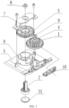
- an adjustment bracket is provided, and the adjustment bracket includes: an adjustment roller 1, an adjustment foot 2, and an adjustment foot gear 3.
- An adjustment gear 4 is fixed to the adjustment roller 1, and the adjustment gear 4 is engaged with the adjustment foot gear 3.
- the adjustment foot gear 3 is provided with internal threads at its central position, and the adjustment foot 2 is provided with external threads at its outer wall. The adjustment foot 2 and the adjustment foot gear 3 are connected through a screw joint of the internal and external threads.
- a pitch angle or height of an electronic device such as a projector can be adjusted by a combination of a gear transmission and threads, thereby achieving a simple structure and a convenient operation.
- the outer wall of the adjustment foot 2 is provided with a limit portion and a transmission portion, and the external threads are provided on the transmission portion.
- a first through hole is provided at the center position of the adjustment foot gear 3, the internal thread is provided on an inner wall of a lower portion of the first through hole, and a recessed portion is provided at an upper portion of the first through hole.
- the limit portion is formed as two mutually parallel flat surfaces
- the transmission portion is formed as two arcuate surfaces connecting the two mutually parallel flat surfaces, so that the outer wall of the adjustment foot is formed as a non-circumferential structure.
- Such a non-circumferential structure maintains the adjustment foot 2 in a non-rotation state, and the adjustment foot 2 is only allowed to move up and down through threads structure to adjust the height of the projector, thereby adjusting the pitch angle of the projector.
- the limit portion may be formed as a polygon surface, an arcuate surface, or the like, and the transmission portion may be formed as a spiral surface.
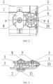
- an upper case (not shown) and a lower case 5 are provided, and the adjustment roller 1 is disposed at a connection between the upper case and the lower case 5, thereby avoiding a process of grooving and opening a hole in the case.
- such an arrangement is an aesthetic design, and blocks a dust entering path. In this way, a slot for receiving the adjustment roller 1 can be provided only in the lower case 5 or the upper case, thereby reducing a processing complexity.
- the adjustment roller 1 is disposed at a side wall of the projector. Most part of the adjustment roller 1 is disposed inside the case of the projector, while only a small part of the adjustment roller 1 is exposed to the operator who operates the roller to rotate, and the adjustment foot gear 3 is driven to rotate by the adjustment gear 4 that is formed in one piece with the adjustment roller 1.
- the adjustment foot gear 3 rotates, the adjustment foot gear 3 is fixed in a vertical direction, and thus the adjustment foot gear 3 can only rotate. Since the limit portion of adjustment foot 2 is limited and fixed, the adjustment foot 2 is fixed in a rotation direction and cannot rotate. Therefore, the adjustment foot gear 3 together with a bottom of the case move up and down relative to the adjustment foot 2, thereby adjusting the telescopic length of the adjustment foot 2.
- the lower case 5 is provided with a protruding arcuate structure 6, and the arcuate structure 6 is fixed and connected to a lower portion of the adjustment foot gear 3.
- An upper portion of the adjustment foot gear 3 is provided with a gear cover 7, the gear cover 7 is provided with an indention structure adapted to the recessed portion, and the indention structure abuts against the recessed portion.
- the lower case 5 is provided with a second through hole adapted to a shape of the outer wall of the adjustment foot 2, and the adjustment foot 2 penetrates the lower case 5 via the second through hole.
- the outer wall of the adjustment foot 2 is provided with a limit protrusion at a lower end thereof.
- An upper end of the adjustment foot 2 is connected to a first screw 8, and the first screw 8 is movably arranged in the indention structure by a shim.
- the first screw 8 is a mechanical flange nail.
- the shape of the outer wall of the adjustment foot 2 is respectively adapted to a lower portion of the first through hole and to the second through hole.
- the arcuate structure 6, limits the adjustment foot gear 3, and the arcuate structure 6 is formed in an arcuate shape instead of a circle shape, so as to provide a receiving space for the adjustment roller 1.
- the adjustment gear 4 drives the adjustment foot gear 3 to rotate relative to the adjustment foot 2 so as to move up and down along an axis of the adjustment foot 2.
- the adjustment foot gear 3 acts on the arcuate structure on the gear cover 7 or the lower case 5, such that the lower case 5 moves up and down relative to the adjustment foot 2 so as to adjust the telescopic length of the adjustment foot 2 relative to the lower case 5, thereby adjusting the pitch angle or height of electronic devices such as the projector.
- This recess design also provides the adjustment roller 1 with a rotating space, so that an adjustment roller portion of the adjustment roller 1 can be as close as possible to a lower position, close to the lower case 5 (i.e., the adjustment gear 4 is located at an upper position), so that a joint between the upper case and the lower case 5 of the projector is arranged as lower as possible.
- an aesthetic design is achieved, and it is convenient for maintenance and disassembly, as the lower case 5 is arranged lower and the parts close to a side of the projector can be maintained in an easier way.
- the lower case 5 is provided with a fixation structure for fixing the adjustment roller 1.
- the fixation structure includes a circular base and a cylindrical support structure. A bottom end of the cylindrical support structure is fixed and connected to the circular base. A top end of the cylindrical support structure is provided with a second screw 9.
- the second screw 9 is a flange self-tapping screw.
- a through hole is provided at a center position of the adjustment roller 1, and an inner diameter of the through hole is in interference fit with an outer diameter of the cylindrical support structure.
- a roller decoration part 10 is provided outside the adjustment roller 1, and the roller decoration part 10 partially covers a periphery of the adjustment roller 1. Moreover, the roller decoration part 10 is provided with an opening for exposing and adjusting the adjustment roller 1.
- the roller decoration part 10 has both decorative and dustproof functions.
- the lower end of the adjustment foot is further provided with a silicone pad 11.
- the adjustment bracket may be provided at left and right sides of the projector, respectively, or is merely provided at a front side.
- a projector is provided.
- the projector includes the adjustment bracket described in Example 1 and conventional structures of the projector, such as an optical structure, a light source structure, a heat dissipation structure and the like.
- adjustment of the pitch angle or height of an electronic device such as a projector is achieved by a combination of a gear transmission and threads, and a structure thereof is simple and an operation thereof is convenient.
Landscapes
- Engineering & Computer Science (AREA)
- General Engineering & Computer Science (AREA)
- Mechanical Engineering (AREA)
- Physics & Mathematics (AREA)
- General Physics & Mathematics (AREA)
- Projection Apparatus (AREA)
- Transforming Electric Information Into Light Information (AREA)
Claims (13)
- Support de réglage, comprenant :un rouleau de réglage (1) ;un pied de réglage (2) ; ;un pignon de pied de réglage (3) ; etun boîtier inférieur (5),dans lequel un pignon de réglage (4) est fixé au rouleau de réglage (1), le pignon de réglage (4) est engagé avec le pignon du pied de réglage (3), le pignon du pied de réglage (3) est pourvu de filets internes à une position centrale, le pied de réglage (2) est pourvu de filets externes sur une paroi extérieure de celui-ci, et le pied de réglage (2) et le pignon de pied de réglage (3) sont reliés par un joint à vis des filets internes et des filets externes ;caractérisé en ce quele boîtier inférieur (5) est pourvu d'une structure arquée saillante, et la structure arquée saillante est une limitation inférieure du pignon de pied de réglage (3) ;la structure arquée de cercle est formée en arc de cercle, de manière à fournir un espace de réception pour le rouleau de réglage (1).
- Support de réglage selon la revendication 1, dans lequel la paroi extérieure du pied de réglage (2) comprend une partie de limite et une partie de transmission, et les filets externes sont prévus sur la partie de transmission, le boîtier inférieur (5) est pourvu d'un deuxième trou traversant dont la forme est adaptée pour s'adapter à une forme de la paroi extérieure du pied de réglage (2), et le pied de réglage (2) pénètre dans le boîtier inférieur (5) via le deuxième trou traversant.
- Support de réglage selon la revendication 2, dans lequel la partie de limite est formée de deux surfaces plates mutuellement parallèles, et la partie de transmission est formée de deux surfaces arquées reliant les deux surfaces plates mutuellement parallèles, de sorte que la paroi extérieure du pied de réglage (2) est formée d'une structure non circonférentielle.
- Support de réglage selon la revendication 1, dans lequel un premier trou traversant est prévu à la position centrale du pignon du pied de réglage (3), les filets internes sont prévus sur une paroi intérieure d'une partie inférieure du premier trou traversant, et une partie évidée est prévue à une partie supérieure du premier trou traversant, etune partie supérieure du pignon de pied de réglage (3) est pourvue d'un couvercle de pignon (7), le couvercle de pignon (7) est pourvu d'une structure d'évidement adaptée à la partie évidée, et la structure d'évidement vient en butée contre la partie évidée, etune extrémité supérieure du pied de réglage (2) est reliée à une première vis (8), et la première vis (8) est disposée de manière mobile dans la structure d'indentation.
- Support de réglage selon la revendication 2, comprenant en outre un boîtier inférieur (5), dans lequel le rouleau de réglage (1) est disposé au niveau d'une connexion entre le boîtier supérieur et le boîtier inférieur (5).
- Support de réglage selon la revendication 4, dans lequel la paroi extérieure d'une partie inférieure du pied de réglage (2) est pourvue d'une saillie de limite.
- Support de réglage selon la revendication 2, dans lequel le boîtier inférieur (5) est pourvu d'une structure de fixation pour fixer le rouleau de réglage (1), et la structure de fixation comprend une base circulaire et une structure de support cylindrique ; une extrémité inférieure de la structure de support cylindrique est fixée et reliée à la base circulaire, et une extrémité supérieure de la structure de support cylindrique est pourvue d'une deuxième vis (9).
- Support de réglage selon la revendication 7, dans lequel un trou traversant est prévu à une position centrale du rouleau de réglage (1), et un diamètre intérieur du trou traversant est en ajustement serré avec un diamètre extérieur de la structure de support cylindrique.
- Support de réglage selon la revendication 1, dans lequel une partie de décoration de rouleau (10) est prévue à l'extérieur du rouleau de réglage (1).
- Support de réglage selon la revendication 1, dans lequel une extrémité inférieure du pied de réglage (2) est en outre pourvue d'un tampon de silicone (11).
- Support de réglage selon la revendication 1, dans lequel le pignon de réglage (4) est disposé à une extrémité supérieure du rouleau de réglage (1) et formé d'une seule pièce avec le rouleau de réglage (1).
- Support de réglage selon la revendication 1, dans lequel le pignon de réglage (4) a un diamètre inférieur à celui du rouleau de réglage (1).
- Projecteur, comprenant le support de réglage selon l'une quelconque des revendications 1 à 12.
Applications Claiming Priority (2)
| Application Number | Priority Date | Filing Date | Title |
|---|---|---|---|
| CN201710346632.7A CN108957915B (zh) | 2017-05-17 | 2017-05-17 | 一种调节支架及投影机 |
| PCT/CN2017/094805 WO2018209813A1 (fr) | 2017-05-17 | 2017-07-28 | Support de réglage et projecteur |
Publications (3)
| Publication Number | Publication Date |
|---|---|
| EP3627220A1 EP3627220A1 (fr) | 2020-03-25 |
| EP3627220A4 EP3627220A4 (fr) | 2020-06-03 |
| EP3627220B1 true EP3627220B1 (fr) | 2023-10-18 |
Family
ID=64273276
Family Applications (1)
| Application Number | Title | Priority Date | Filing Date |
|---|---|---|---|
| EP17909744.9A Active EP3627220B1 (fr) | 2017-05-17 | 2017-07-28 | Support de réglage et projecteur |
Country Status (5)
| Country | Link |
|---|---|
| US (1) | US11281079B2 (fr) |
| EP (1) | EP3627220B1 (fr) |
| JP (1) | JP6943980B2 (fr) |
| CN (1) | CN108957915B (fr) |
| WO (1) | WO2018209813A1 (fr) |
Families Citing this family (6)
| Publication number | Priority date | Publication date | Assignee | Title |
|---|---|---|---|---|
| CN108957915B (zh) * | 2017-05-17 | 2024-04-05 | 深圳光峰科技股份有限公司 | 一种调节支架及投影机 |
| CN111810789A (zh) * | 2020-07-15 | 2020-10-23 | 杨明清 | 一种显示屏角度可调的智能终端控制设备 |
| CN112327573A (zh) * | 2020-11-12 | 2021-02-05 | 洪达未 | 一种基于三维动画教学用的动画界面物理成像装置 |
| CN113623510A (zh) * | 2021-05-25 | 2021-11-09 | 国盾(山东)知识产权运营管理有限公司 | 一种便于调节的科技管理创新投影讲解仪 |
| CN113628481B (zh) * | 2021-08-15 | 2022-12-09 | 深圳华兆科技有限公司 | 一种便于调节的多媒体教学设备 |
| CN113932130B (zh) * | 2021-12-16 | 2022-03-18 | 国网山东省电力公司桓台县供电公司 | 一种激光测量距离校准设备 |
Family Cites Families (29)
| Publication number | Priority date | Publication date | Assignee | Title |
|---|---|---|---|---|
| US1417639A (en) * | 1921-03-19 | 1922-05-30 | Daniel L Sterner | Table leveler |
| US4991805A (en) * | 1989-05-17 | 1991-02-12 | Whirlpool Corporation | Refrigerator gear driven leveling system |
| JP2000241875A (ja) * | 1999-02-19 | 2000-09-08 | Fujitsu General Ltd | 画像表示装置 |
| JP4697999B2 (ja) * | 2000-05-31 | 2011-06-08 | 三菱電機株式会社 | 投射型映像表示装置 |
| US6485144B1 (en) | 2000-08-30 | 2002-11-26 | Jung-Huang Liao | Projector hanger frame |
| US6729590B2 (en) | 2002-01-23 | 2004-05-04 | Edward Gabriel | Leveling device |
| JP2004013028A (ja) * | 2002-06-10 | 2004-01-15 | Sony Corp | 画像投射装置 |
| JP2004085726A (ja) * | 2002-08-23 | 2004-03-18 | Seiko Epson Corp | プロジェクタ |
| DE102004022681B3 (de) * | 2004-05-05 | 2005-09-22 | Miele & Cie. Kg | Höhenverstellbarer Fuß für Hausgeräte, wie Wasch- oder Geschirrspülgerät mit einem Schaft der standseitig mit einem Fußteller bestückt ist |
| US7104511B2 (en) * | 2004-09-22 | 2006-09-12 | Hewlett-Packard Development Company, L.P. | Adjustable support for multimedia display device |
| JP2008116577A (ja) * | 2006-11-01 | 2008-05-22 | Sharp Corp | 高さ調整装置及び投射型映像表示装置 |
| JP2008275932A (ja) * | 2007-04-27 | 2008-11-13 | Sharp Corp | 高さ調整機構及び投射型映像表示装置 |
| CN101458437A (zh) * | 2007-12-14 | 2009-06-17 | 鸿富锦精密工业(深圳)有限公司 | 投影仪调整装置 |
| CN201199290Y (zh) * | 2008-05-06 | 2009-02-25 | 芯硕半导体(中国)有限公司 | 整体式精密五轴调整装置 |
| WO2011010354A1 (fr) * | 2009-07-21 | 2011-01-27 | Necディスプレイソリューションズ株式会社 | Dispositif électronique |
| CN102193282B (zh) * | 2010-03-12 | 2012-08-29 | 鸿富锦精密工业(深圳)有限公司 | 投影仪 |
| CN102478755A (zh) * | 2010-11-26 | 2012-05-30 | 中强光电股份有限公司 | 用于投影装置的升降机构 |
| CN102654724B (zh) * | 2011-03-01 | 2014-10-15 | 中强光电股份有限公司 | 投影机及其升降模组 |
| KR102030845B1 (ko) * | 2012-11-13 | 2019-10-11 | 삼성전자주식회사 | 냉장고 및 이에 구비되는 하부힌지모듈 |
| GB2510189A (en) * | 2013-01-29 | 2014-07-30 | Johnson Electric Sa | Vibration Safe Motor Fixation in an Actuator |
| CN106796078B (zh) * | 2015-06-11 | 2020-02-21 | Lg 电子株式会社 | 冰箱和用于冰箱的控制方法 |
| CN204705806U (zh) * | 2015-06-30 | 2015-10-14 | 济宁市技师学院 | 一种投影仪 |
| CN105093797B (zh) * | 2015-07-29 | 2017-02-01 | 海信集团有限公司 | 一种投影显示设备的可调底座及投影显示设备 |
| CN205229648U (zh) * | 2015-11-10 | 2016-05-11 | 海信集团有限公司 | 一种投影机 |
| ITUA20161495A1 (it) * | 2016-03-09 | 2017-09-09 | Leonardo Srl | Sistema di regolazione frontale compatto per piedi di livellamento per mobili |
| CN205923528U (zh) * | 2016-06-05 | 2017-02-08 | 康春生 | 一种学生双层床 |
| CN206056213U (zh) * | 2016-09-14 | 2017-03-29 | 深圳市保怡科技有限公司 | 一种双涡轮的吹地机 |
| CN108957915B (zh) * | 2017-05-17 | 2024-04-05 | 深圳光峰科技股份有限公司 | 一种调节支架及投影机 |
| CN207067634U (zh) * | 2017-05-17 | 2018-03-02 | 深圳市光峰光电技术有限公司 | 一种调节支架及投影机 |
-
2017
- 2017-05-17 CN CN201710346632.7A patent/CN108957915B/zh active Active
- 2017-07-28 EP EP17909744.9A patent/EP3627220B1/fr active Active
- 2017-07-28 WO PCT/CN2017/094805 patent/WO2018209813A1/fr unknown
- 2017-07-28 JP JP2019563500A patent/JP6943980B2/ja active Active
- 2017-07-28 US US16/613,136 patent/US11281079B2/en active Active
Also Published As
| Publication number | Publication date |
|---|---|
| US11281079B2 (en) | 2022-03-22 |
| CN108957915B (zh) | 2024-04-05 |
| EP3627220A1 (fr) | 2020-03-25 |
| EP3627220A4 (fr) | 2020-06-03 |
| US20210080813A1 (en) | 2021-03-18 |
| WO2018209813A1 (fr) | 2018-11-22 |
| CN108957915A (zh) | 2018-12-07 |
| JP6943980B2 (ja) | 2021-10-06 |
| JP2020520479A (ja) | 2020-07-09 |
Similar Documents
| Publication | Publication Date | Title |
|---|---|---|
| EP3627220B1 (fr) | Support de réglage et projecteur | |
| US8066233B2 (en) | Swivel, display device and electronic apparatus | |
| EP3490239B1 (fr) | Caméra vidéo sphérique | |
| WO2021127937A1 (fr) | Dispositif de photographie, appareil électronique et procédé d'utilisation d'appareil électronique | |
| CN203759382U (zh) | 一种确定棱镜片装配角度的设备 | |
| US8120715B2 (en) | Torque limiter, display screen turning apparatus comprising torque limiter and television set including torque limiter | |
| WO2020143462A1 (fr) | Dispositif d'affichage | |
| CN106958731B (zh) | 显示装置 | |
| WO2018076843A1 (fr) | Dispositif d'affichage | |
| CN211427016U (zh) | 一种激光投影设备 | |
| US10120269B2 (en) | Projection apparatus with device for adjusting projection angle of projection image | |
| CN111308837A (zh) | 一种光机引擎及投影设备 | |
| CN105791639A (zh) | 摄像头组件及具有该摄像头组件的电子装置 | |
| CN208207495U (zh) | 一种支撑装置以及投影机 | |
| CN208672893U (zh) | 薄型透镜马达 | |
| KR200390350Y1 (ko) | 회동되는 돔형 카메라 | |
| CN219933592U (zh) | 一种激光投影设备 | |
| AU2014100054A4 (en) | Quickly Assembled Fan | |
| TW201319444A (zh) | 監視器固定結構 | |
| CN208188571U (zh) | 一种支撑装置以及投影机 | |
| TW202042547A (zh) | 顯示裝置 | |
| CN205862001U (zh) | 一种观察镜 | |
| CN205353436U (zh) | 光学模组高度可调的固定装置 | |
| CN220105383U (zh) | 镜片安装组件以及光学装置 | |
| CN219639853U (zh) | 一种多目无级旋转结构光3d相机装置 |
Legal Events
| Date | Code | Title | Description |
|---|---|---|---|
| STAA | Information on the status of an ep patent application or granted ep patent |
Free format text: STATUS: THE INTERNATIONAL PUBLICATION HAS BEEN MADE |
|
| PUAI | Public reference made under article 153(3) epc to a published international application that has entered the european phase |
Free format text: ORIGINAL CODE: 0009012 |
|
| STAA | Information on the status of an ep patent application or granted ep patent |
Free format text: STATUS: REQUEST FOR EXAMINATION WAS MADE |
|
| 17P | Request for examination filed |
Effective date: 20191216 |
|
| AK | Designated contracting states |
Kind code of ref document: A1 Designated state(s): AL AT BE BG CH CY CZ DE DK EE ES FI FR GB GR HR HU IE IS IT LI LT LU LV MC MK MT NL NO PL PT RO RS SE SI SK SM TR |
|
| AX | Request for extension of the european patent |
Extension state: BA ME |
|
| A4 | Supplementary search report drawn up and despatched |
Effective date: 20200506 |
|
| RIC1 | Information provided on ipc code assigned before grant |
Ipc: F16M 11/04 20060101ALI20200428BHEP Ipc: F16M 11/10 20060101ALI20200428BHEP Ipc: G03B 21/14 20060101AFI20200428BHEP |
|
| DAV | Request for validation of the european patent (deleted) | ||
| DAX | Request for extension of the european patent (deleted) | ||
| STAA | Information on the status of an ep patent application or granted ep patent |
Free format text: STATUS: EXAMINATION IS IN PROGRESS |
|
| 17Q | First examination report despatched |
Effective date: 20210806 |
|
| STAA | Information on the status of an ep patent application or granted ep patent |
Free format text: STATUS: EXAMINATION IS IN PROGRESS |
|
| RIC1 | Information provided on ipc code assigned before grant |
Ipc: F16M 7/00 20060101ALI20230619BHEP Ipc: F16M 11/18 20060101ALI20230619BHEP Ipc: F16M 11/04 20060101ALI20230619BHEP Ipc: G03B 21/14 20060101AFI20230619BHEP |
|
| GRAP | Despatch of communication of intention to grant a patent |
Free format text: ORIGINAL CODE: EPIDOSNIGR1 |
|
| STAA | Information on the status of an ep patent application or granted ep patent |
Free format text: STATUS: GRANT OF PATENT IS INTENDED |
|
| INTG | Intention to grant announced |
Effective date: 20230807 |
|
| GRAS | Grant fee paid |
Free format text: ORIGINAL CODE: EPIDOSNIGR3 |
|
| GRAA | (expected) grant |
Free format text: ORIGINAL CODE: 0009210 |
|
| STAA | Information on the status of an ep patent application or granted ep patent |
Free format text: STATUS: THE PATENT HAS BEEN GRANTED |
|
| AK | Designated contracting states |
Kind code of ref document: B1 Designated state(s): AL AT BE BG CH CY CZ DE DK EE ES FI FR GB GR HR HU IE IS IT LI LT LU LV MC MK MT NL NO PL PT RO RS SE SI SK SM TR |
|
| REG | Reference to a national code |
Ref country code: GB Ref legal event code: FG4D |
|
| REG | Reference to a national code |
Ref country code: CH Ref legal event code: EP |
|
| REG | Reference to a national code |
Ref country code: IE Ref legal event code: FG4D |
|
| REG | Reference to a national code |
Ref country code: DE Ref legal event code: R096 Ref document number: 602017075560 Country of ref document: DE |
|
| REG | Reference to a national code |
Ref country code: LT Ref legal event code: MG9D |
|
| REG | Reference to a national code |
Ref country code: NL Ref legal event code: MP Effective date: 20231018 |
|
| REG | Reference to a national code |
Ref country code: AT Ref legal event code: MK05 Ref document number: 1622969 Country of ref document: AT Kind code of ref document: T Effective date: 20231018 |
|
| PG25 | Lapsed in a contracting state [announced via postgrant information from national office to epo] |
Ref country code: NL Free format text: LAPSE BECAUSE OF FAILURE TO SUBMIT A TRANSLATION OF THE DESCRIPTION OR TO PAY THE FEE WITHIN THE PRESCRIBED TIME-LIMIT Effective date: 20231018 |
|
| PG25 | Lapsed in a contracting state [announced via postgrant information from national office to epo] |
Ref country code: GR Free format text: LAPSE BECAUSE OF FAILURE TO SUBMIT A TRANSLATION OF THE DESCRIPTION OR TO PAY THE FEE WITHIN THE PRESCRIBED TIME-LIMIT Effective date: 20240119 |
|
| PG25 | Lapsed in a contracting state [announced via postgrant information from national office to epo] |
Ref country code: IS Free format text: LAPSE BECAUSE OF FAILURE TO SUBMIT A TRANSLATION OF THE DESCRIPTION OR TO PAY THE FEE WITHIN THE PRESCRIBED TIME-LIMIT Effective date: 20240218 |
|
| PG25 | Lapsed in a contracting state [announced via postgrant information from national office to epo] |
Ref country code: LT Free format text: LAPSE BECAUSE OF FAILURE TO SUBMIT A TRANSLATION OF THE DESCRIPTION OR TO PAY THE FEE WITHIN THE PRESCRIBED TIME-LIMIT Effective date: 20231018 |
|
| PG25 | Lapsed in a contracting state [announced via postgrant information from national office to epo] |
Ref country code: AT Free format text: LAPSE BECAUSE OF FAILURE TO SUBMIT A TRANSLATION OF THE DESCRIPTION OR TO PAY THE FEE WITHIN THE PRESCRIBED TIME-LIMIT Effective date: 20231018 |
|
| PG25 | Lapsed in a contracting state [announced via postgrant information from national office to epo] |
Ref country code: ES Free format text: LAPSE BECAUSE OF FAILURE TO SUBMIT A TRANSLATION OF THE DESCRIPTION OR TO PAY THE FEE WITHIN THE PRESCRIBED TIME-LIMIT Effective date: 20231018 |
|
| PG25 | Lapsed in a contracting state [announced via postgrant information from national office to epo] |
Ref country code: LT Free format text: LAPSE BECAUSE OF FAILURE TO SUBMIT A TRANSLATION OF THE DESCRIPTION OR TO PAY THE FEE WITHIN THE PRESCRIBED TIME-LIMIT Effective date: 20231018 Ref country code: IS Free format text: LAPSE BECAUSE OF FAILURE TO SUBMIT A TRANSLATION OF THE DESCRIPTION OR TO PAY THE FEE WITHIN THE PRESCRIBED TIME-LIMIT Effective date: 20240218 Ref country code: GR Free format text: LAPSE BECAUSE OF FAILURE TO SUBMIT A TRANSLATION OF THE DESCRIPTION OR TO PAY THE FEE WITHIN THE PRESCRIBED TIME-LIMIT Effective date: 20240119 Ref country code: ES Free format text: LAPSE BECAUSE OF FAILURE TO SUBMIT A TRANSLATION OF THE DESCRIPTION OR TO PAY THE FEE WITHIN THE PRESCRIBED TIME-LIMIT Effective date: 20231018 Ref country code: BG Free format text: LAPSE BECAUSE OF FAILURE TO SUBMIT A TRANSLATION OF THE DESCRIPTION OR TO PAY THE FEE WITHIN THE PRESCRIBED TIME-LIMIT Effective date: 20240118 Ref country code: AT Free format text: LAPSE BECAUSE OF FAILURE TO SUBMIT A TRANSLATION OF THE DESCRIPTION OR TO PAY THE FEE WITHIN THE PRESCRIBED TIME-LIMIT Effective date: 20231018 Ref country code: PT Free format text: LAPSE BECAUSE OF FAILURE TO SUBMIT A TRANSLATION OF THE DESCRIPTION OR TO PAY THE FEE WITHIN THE PRESCRIBED TIME-LIMIT Effective date: 20240219 |
|
| PG25 | Lapsed in a contracting state [announced via postgrant information from national office to epo] |
Ref country code: SE Free format text: LAPSE BECAUSE OF FAILURE TO SUBMIT A TRANSLATION OF THE DESCRIPTION OR TO PAY THE FEE WITHIN THE PRESCRIBED TIME-LIMIT Effective date: 20231018 Ref country code: RS Free format text: LAPSE BECAUSE OF FAILURE TO SUBMIT A TRANSLATION OF THE DESCRIPTION OR TO PAY THE FEE WITHIN THE PRESCRIBED TIME-LIMIT Effective date: 20231018 Ref country code: PL Free format text: LAPSE BECAUSE OF FAILURE TO SUBMIT A TRANSLATION OF THE DESCRIPTION OR TO PAY THE FEE WITHIN THE PRESCRIBED TIME-LIMIT Effective date: 20231018 Ref country code: NO Free format text: LAPSE BECAUSE OF FAILURE TO SUBMIT A TRANSLATION OF THE DESCRIPTION OR TO PAY THE FEE WITHIN THE PRESCRIBED TIME-LIMIT Effective date: 20240118 Ref country code: LV Free format text: LAPSE BECAUSE OF FAILURE TO SUBMIT A TRANSLATION OF THE DESCRIPTION OR TO PAY THE FEE WITHIN THE PRESCRIBED TIME-LIMIT Effective date: 20231018 Ref country code: HR Free format text: LAPSE BECAUSE OF FAILURE TO SUBMIT A TRANSLATION OF THE DESCRIPTION OR TO PAY THE FEE WITHIN THE PRESCRIBED TIME-LIMIT Effective date: 20231018 |
|
| PG25 | Lapsed in a contracting state [announced via postgrant information from national office to epo] |
Ref country code: DK Free format text: LAPSE BECAUSE OF FAILURE TO SUBMIT A TRANSLATION OF THE DESCRIPTION OR TO PAY THE FEE WITHIN THE PRESCRIBED TIME-LIMIT Effective date: 20231018 |
|
| REG | Reference to a national code |
Ref country code: DE Ref legal event code: R097 Ref document number: 602017075560 Country of ref document: DE |
|
| PG25 | Lapsed in a contracting state [announced via postgrant information from national office to epo] |
Ref country code: CZ Free format text: LAPSE BECAUSE OF FAILURE TO SUBMIT A TRANSLATION OF THE DESCRIPTION OR TO PAY THE FEE WITHIN THE PRESCRIBED TIME-LIMIT Effective date: 20231018 |
|
| PG25 | Lapsed in a contracting state [announced via postgrant information from national office to epo] |
Ref country code: SK Free format text: LAPSE BECAUSE OF FAILURE TO SUBMIT A TRANSLATION OF THE DESCRIPTION OR TO PAY THE FEE WITHIN THE PRESCRIBED TIME-LIMIT Effective date: 20231018 |
|
| PG25 | Lapsed in a contracting state [announced via postgrant information from national office to epo] |
Ref country code: SM Free format text: LAPSE BECAUSE OF FAILURE TO SUBMIT A TRANSLATION OF THE DESCRIPTION OR TO PAY THE FEE WITHIN THE PRESCRIBED TIME-LIMIT Effective date: 20231018 Ref country code: SK Free format text: LAPSE BECAUSE OF FAILURE TO SUBMIT A TRANSLATION OF THE DESCRIPTION OR TO PAY THE FEE WITHIN THE PRESCRIBED TIME-LIMIT Effective date: 20231018 Ref country code: RO Free format text: LAPSE BECAUSE OF FAILURE TO SUBMIT A TRANSLATION OF THE DESCRIPTION OR TO PAY THE FEE WITHIN THE PRESCRIBED TIME-LIMIT Effective date: 20231018 Ref country code: IT Free format text: LAPSE BECAUSE OF FAILURE TO SUBMIT A TRANSLATION OF THE DESCRIPTION OR TO PAY THE FEE WITHIN THE PRESCRIBED TIME-LIMIT Effective date: 20231018 Ref country code: EE Free format text: LAPSE BECAUSE OF FAILURE TO SUBMIT A TRANSLATION OF THE DESCRIPTION OR TO PAY THE FEE WITHIN THE PRESCRIBED TIME-LIMIT Effective date: 20231018 Ref country code: DK Free format text: LAPSE BECAUSE OF FAILURE TO SUBMIT A TRANSLATION OF THE DESCRIPTION OR TO PAY THE FEE WITHIN THE PRESCRIBED TIME-LIMIT Effective date: 20231018 Ref country code: CZ Free format text: LAPSE BECAUSE OF FAILURE TO SUBMIT A TRANSLATION OF THE DESCRIPTION OR TO PAY THE FEE WITHIN THE PRESCRIBED TIME-LIMIT Effective date: 20231018 |
|
| PGFP | Annual fee paid to national office [announced via postgrant information from national office to epo] |
Ref country code: FR Payment date: 20240619 Year of fee payment: 8 |
|
| PLBE | No opposition filed within time limit |
Free format text: ORIGINAL CODE: 0009261 |
|
| STAA | Information on the status of an ep patent application or granted ep patent |
Free format text: STATUS: NO OPPOSITION FILED WITHIN TIME LIMIT |
|
| 26N | No opposition filed |
Effective date: 20240719 |
|
| PGFP | Annual fee paid to national office [announced via postgrant information from national office to epo] |
Ref country code: DE Payment date: 20240712 Year of fee payment: 8 |
|
| PGFP | Annual fee paid to national office [announced via postgrant information from national office to epo] |
Ref country code: GB Payment date: 20240729 Year of fee payment: 8 |