EP3627220B1 - Adjusting support and projector - Google Patents
Adjusting support and projector Download PDFInfo
- Publication number
- EP3627220B1 EP3627220B1 EP17909744.9A EP17909744A EP3627220B1 EP 3627220 B1 EP3627220 B1 EP 3627220B1 EP 17909744 A EP17909744 A EP 17909744A EP 3627220 B1 EP3627220 B1 EP 3627220B1
- Authority
- EP
- European Patent Office
- Prior art keywords
- adjustment
- gear
- foot
- roller
- bracket according
- Prior art date
- Legal status (The legal status is an assumption and is not a legal conclusion. Google has not performed a legal analysis and makes no representation as to the accuracy of the status listed.)
- Active
Links
- 230000005540 biological transmission Effects 0.000 claims description 14
- 238000005034 decoration Methods 0.000 claims description 7
- 229920001296 polysiloxane Polymers 0.000 claims description 4
- 238000000034 method Methods 0.000 description 9
- 238000010586 diagram Methods 0.000 description 2
- 239000000428 dust Substances 0.000 description 1
- 230000000694 effects Effects 0.000 description 1
- 230000017525 heat dissipation Effects 0.000 description 1
- 238000012423 maintenance Methods 0.000 description 1
- 230000003287 optical effect Effects 0.000 description 1
- 238000010079 rubber tapping Methods 0.000 description 1
Images

Classifications
-
- G—PHYSICS
- G03—PHOTOGRAPHY; CINEMATOGRAPHY; ANALOGOUS TECHNIQUES USING WAVES OTHER THAN OPTICAL WAVES; ELECTROGRAPHY; HOLOGRAPHY
- G03B—APPARATUS OR ARRANGEMENTS FOR TAKING PHOTOGRAPHS OR FOR PROJECTING OR VIEWING THEM; APPARATUS OR ARRANGEMENTS EMPLOYING ANALOGOUS TECHNIQUES USING WAVES OTHER THAN OPTICAL WAVES; ACCESSORIES THEREFOR
- G03B21/00—Projectors or projection-type viewers; Accessories therefor
- G03B21/14—Details
- G03B21/145—Housing details, e.g. position adjustments thereof
-
- F—MECHANICAL ENGINEERING; LIGHTING; HEATING; WEAPONS; BLASTING
- F16—ENGINEERING ELEMENTS AND UNITS; GENERAL MEASURES FOR PRODUCING AND MAINTAINING EFFECTIVE FUNCTIONING OF MACHINES OR INSTALLATIONS; THERMAL INSULATION IN GENERAL
- F16M—FRAMES, CASINGS OR BEDS OF ENGINES, MACHINES OR APPARATUS, NOT SPECIFIC TO ENGINES, MACHINES OR APPARATUS PROVIDED FOR ELSEWHERE; STANDS; SUPPORTS
- F16M11/00—Stands or trestles as supports for apparatus or articles placed thereon Stands for scientific apparatus such as gravitational force meters
- F16M11/02—Heads
- F16M11/04—Means for attachment of apparatus; Means allowing adjustment of the apparatus relatively to the stand
- F16M11/043—Allowing translations
- F16M11/046—Allowing translations adapted to upward-downward translation movement
-
- F—MECHANICAL ENGINEERING; LIGHTING; HEATING; WEAPONS; BLASTING
- F16—ENGINEERING ELEMENTS AND UNITS; GENERAL MEASURES FOR PRODUCING AND MAINTAINING EFFECTIVE FUNCTIONING OF MACHINES OR INSTALLATIONS; THERMAL INSULATION IN GENERAL
- F16M—FRAMES, CASINGS OR BEDS OF ENGINES, MACHINES OR APPARATUS, NOT SPECIFIC TO ENGINES, MACHINES OR APPARATUS PROVIDED FOR ELSEWHERE; STANDS; SUPPORTS
- F16M11/00—Stands or trestles as supports for apparatus or articles placed thereon Stands for scientific apparatus such as gravitational force meters
- F16M11/02—Heads
- F16M11/04—Means for attachment of apparatus; Means allowing adjustment of the apparatus relatively to the stand
- F16M11/06—Means for attachment of apparatus; Means allowing adjustment of the apparatus relatively to the stand allowing pivoting
- F16M11/10—Means for attachment of apparatus; Means allowing adjustment of the apparatus relatively to the stand allowing pivoting around a horizontal axis
-
- F—MECHANICAL ENGINEERING; LIGHTING; HEATING; WEAPONS; BLASTING
- F16—ENGINEERING ELEMENTS AND UNITS; GENERAL MEASURES FOR PRODUCING AND MAINTAINING EFFECTIVE FUNCTIONING OF MACHINES OR INSTALLATIONS; THERMAL INSULATION IN GENERAL
- F16M—FRAMES, CASINGS OR BEDS OF ENGINES, MACHINES OR APPARATUS, NOT SPECIFIC TO ENGINES, MACHINES OR APPARATUS PROVIDED FOR ELSEWHERE; STANDS; SUPPORTS
- F16M11/00—Stands or trestles as supports for apparatus or articles placed thereon Stands for scientific apparatus such as gravitational force meters
- F16M11/02—Heads
- F16M11/18—Heads with mechanism for moving the apparatus relatively to the stand
-
- F—MECHANICAL ENGINEERING; LIGHTING; HEATING; WEAPONS; BLASTING
- F16—ENGINEERING ELEMENTS AND UNITS; GENERAL MEASURES FOR PRODUCING AND MAINTAINING EFFECTIVE FUNCTIONING OF MACHINES OR INSTALLATIONS; THERMAL INSULATION IN GENERAL
- F16M—FRAMES, CASINGS OR BEDS OF ENGINES, MACHINES OR APPARATUS, NOT SPECIFIC TO ENGINES, MACHINES OR APPARATUS PROVIDED FOR ELSEWHERE; STANDS; SUPPORTS
- F16M7/00—Details of attaching or adjusting engine beds, frames, or supporting-legs on foundation or base; Attaching non-moving engine parts, e.g. cylinder blocks
-
- F—MECHANICAL ENGINEERING; LIGHTING; HEATING; WEAPONS; BLASTING
- F16—ENGINEERING ELEMENTS AND UNITS; GENERAL MEASURES FOR PRODUCING AND MAINTAINING EFFECTIVE FUNCTIONING OF MACHINES OR INSTALLATIONS; THERMAL INSULATION IN GENERAL
- F16M—FRAMES, CASINGS OR BEDS OF ENGINES, MACHINES OR APPARATUS, NOT SPECIFIC TO ENGINES, MACHINES OR APPARATUS PROVIDED FOR ELSEWHERE; STANDS; SUPPORTS
- F16M2200/00—Details of stands or supports
- F16M2200/08—Foot or support base
Definitions
- the present disclosure relates to the technical field of electronic devices, and in particular, to an adjustment bracket and a projector.
- Projectors are more and more frequently used in education, home, and engineering demonstrations, and people use the projectors to project pictures or videos on a screen or wall to obtain a magnified display.
- Projectors are more and more frequently used in education, home, and engineering demonstrations, and people use the projectors to project pictures or videos on a screen or wall to obtain a magnified display.
- it is usually necessary to adjust a pitch angle or height of the projector to obtain a better display effect.
- the projector is provided with a supporting foot at a bottom position that can be rotated to adjust a height, and then the pitch angle or height of the projector can be adjusted by changing a telescopic length of the foot relative to the projector.
- a design generally requires the user to lift the projector before adjusting the foot, which results in an inconvenient and inaccurate adjustment, and it easily leads to deviation of a placement position of the projector, which is not conducive to adjustment during the projection process.
- a main purpose of the present disclosure is to provide an adjustment bracket and a projector, which can achieve an adjustment of a pitch angle or height of an electronic device such as projector by a combination of a gear transmission and threads, a simple structure, and a convenient operation.
- an adjustment bracket including: an adjustment roller; an adjustment foot; an adjustment foot gear with a first axis; and a lower case, wherein an adjustment gear is fixed to the adjustment roller, the adjustment gear is engaged with the adjustment foot gear, the adjustment foot gear is provided with internal threads at a center position thereof, the adjustment foot is provided with external threads on an outer wall thereof, and the adjustment foot and the adjustment foot gear are connected through a screw joint of the internal threads and the external threads; wherein the lower case is provided with a protruding arcuate structure, and the protruding arcuate structure is a lower limitation of the adjustment foot gear; the arcuate structure is formed in an arcuate shape, so as to provide a receiving space for the adjustment roller.
- the outer wall of the adjustment foot comprises a limit portion and a transmission portion, and the external threads are provided on the transmission portion, the lower case is provided with a second through hole whose shape is adapted to fit with a shape of the outer wall of the adjustment foot, and the adjustment foot penetrates the lower case via the second through hole.
- the limit portion is formed as two mutually parallel flat surfaces
- the transmission portion is formed as two arcuate surfaces connecting the two mutually parallel flat surfaces, so that the outer wall of the adjustment foot is formed as a non-circumferential structure.
- a first through hole is provided at the center position of the adjustment foot gear, the internal threads are provided on an inner wall of a lower portion of the first through hole, and a recessed portion is provided at an upper portion of the first through hole, and an upper portion of the adjustment foot gear is provided with a gear cover, the gear cover is provided with an indention structure adapted to the recessed portion, and the indention structure abuts against the recessed portion, and an upper end of the adjustment foot is connected to a first screw, and the first screw is movably arranged in the indention structure.
- the adjustment bracket further comprises a lower case, wherein the adjustment roller is arranged at a connection between the upper case and the lower case.
- the outer wall of a lower portion of the adjustment foot is provided with a limit protrusion.
- the lower case is provided with a fixation structure for fixing the adjustment roller, and the fixation structure comprises a circular base and a cylindrical support structure; a bottom end of the cylindrical support structure is fixed and connected to the circular base, and a top end of the cylindrical support structure is provided with a second screw.
- a through hole is provided at a center position of the adjustment roller, and an inner diameter of the through hole is in interference fit with an outer diameter of the cylindrical support structure
- a roller decoration part is provided outside the adjustment roller.
- a lower end of the adjustment foot is further provided with a silicone pad.
- the adjustment gear is arranged at an upper end of the adjustment roller and formed into one piece with the adjustment roller.
- the adjustment gear has a smaller diameter than the adjustment roller.
- the present disclosure provides a projector including the adjustment bracket described above.
- the present disclosure provides an adjustment bracket and a projector.
- the adjustment bracket includes: an adjustment roller; an adjustment foot; an adjustment foot gear with a first axis; and a lower case, wherein an adjustment gear is fixed to the adjustment roller, the adjustment gear is engaged with the adjustment foot gear, the adjustment foot gear is provided with internal threads at a center position thereof, the adjustment foot is provided with external threads on an outer wall thereof, and the adjustment foot and the adjustment foot gear are connected through a screw joint of the internal threads and the external threads; wherein the lower case is provided with a protruding arcuate structure, and the protruding arcuate structure is a lower limitation of the adjustment foot gear; the arcuate structure is formed in an arcuate shape, so as to provide a receiving space for the adjustment roller.
- a pitch angle or height of an electronic device such as a projector can be adjusted by a combination of a gear transmission and threads, and a structure thereof is simple and an operation thereof is convenient.
- module means merely for illustration, but not have specific meanings. Therefore, “module” and “component” can represent the same element.
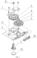
- an adjustment bracket is provided, and the adjustment bracket includes: an adjustment roller 1, an adjustment foot 2, and an adjustment foot gear 3.
- An adjustment gear 4 is fixed to the adjustment roller 1, and the adjustment gear 4 is engaged with the adjustment foot gear 3.
- the adjustment foot gear 3 is provided with internal threads at its central position, and the adjustment foot 2 is provided with external threads at its outer wall. The adjustment foot 2 and the adjustment foot gear 3 are connected through a screw joint of the internal and external threads.
- a pitch angle or height of an electronic device such as a projector can be adjusted by a combination of a gear transmission and threads, thereby achieving a simple structure and a convenient operation.
- the outer wall of the adjustment foot 2 is provided with a limit portion and a transmission portion, and the external threads are provided on the transmission portion.
- a first through hole is provided at the center position of the adjustment foot gear 3, the internal thread is provided on an inner wall of a lower portion of the first through hole, and a recessed portion is provided at an upper portion of the first through hole.
- the limit portion is formed as two mutually parallel flat surfaces
- the transmission portion is formed as two arcuate surfaces connecting the two mutually parallel flat surfaces, so that the outer wall of the adjustment foot is formed as a non-circumferential structure.
- Such a non-circumferential structure maintains the adjustment foot 2 in a non-rotation state, and the adjustment foot 2 is only allowed to move up and down through threads structure to adjust the height of the projector, thereby adjusting the pitch angle of the projector.
- the limit portion may be formed as a polygon surface, an arcuate surface, or the like, and the transmission portion may be formed as a spiral surface.
- an upper case (not shown) and a lower case 5 are provided, and the adjustment roller 1 is disposed at a connection between the upper case and the lower case 5, thereby avoiding a process of grooving and opening a hole in the case.
- such an arrangement is an aesthetic design, and blocks a dust entering path. In this way, a slot for receiving the adjustment roller 1 can be provided only in the lower case 5 or the upper case, thereby reducing a processing complexity.
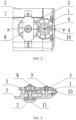
- the adjustment roller 1 is disposed at a side wall of the projector. Most part of the adjustment roller 1 is disposed inside the case of the projector, while only a small part of the adjustment roller 1 is exposed to the operator who operates the roller to rotate, and the adjustment foot gear 3 is driven to rotate by the adjustment gear 4 that is formed in one piece with the adjustment roller 1.
- the adjustment foot gear 3 rotates, the adjustment foot gear 3 is fixed in a vertical direction, and thus the adjustment foot gear 3 can only rotate. Since the limit portion of adjustment foot 2 is limited and fixed, the adjustment foot 2 is fixed in a rotation direction and cannot rotate. Therefore, the adjustment foot gear 3 together with a bottom of the case move up and down relative to the adjustment foot 2, thereby adjusting the telescopic length of the adjustment foot 2.
- the lower case 5 is provided with a protruding arcuate structure 6, and the arcuate structure 6 is fixed and connected to a lower portion of the adjustment foot gear 3.
- An upper portion of the adjustment foot gear 3 is provided with a gear cover 7, the gear cover 7 is provided with an indention structure adapted to the recessed portion, and the indention structure abuts against the recessed portion.
- the lower case 5 is provided with a second through hole adapted to a shape of the outer wall of the adjustment foot 2, and the adjustment foot 2 penetrates the lower case 5 via the second through hole.
- the outer wall of the adjustment foot 2 is provided with a limit protrusion at a lower end thereof.
- An upper end of the adjustment foot 2 is connected to a first screw 8, and the first screw 8 is movably arranged in the indention structure by a shim.
- the first screw 8 is a mechanical flange nail.
- the shape of the outer wall of the adjustment foot 2 is respectively adapted to a lower portion of the first through hole and to the second through hole.
- the arcuate structure 6, limits the adjustment foot gear 3, and the arcuate structure 6 is formed in an arcuate shape instead of a circle shape, so as to provide a receiving space for the adjustment roller 1.
- the adjustment gear 4 drives the adjustment foot gear 3 to rotate relative to the adjustment foot 2 so as to move up and down along an axis of the adjustment foot 2.
- the adjustment foot gear 3 acts on the arcuate structure on the gear cover 7 or the lower case 5, such that the lower case 5 moves up and down relative to the adjustment foot 2 so as to adjust the telescopic length of the adjustment foot 2 relative to the lower case 5, thereby adjusting the pitch angle or height of electronic devices such as the projector.
- This recess design also provides the adjustment roller 1 with a rotating space, so that an adjustment roller portion of the adjustment roller 1 can be as close as possible to a lower position, close to the lower case 5 (i.e., the adjustment gear 4 is located at an upper position), so that a joint between the upper case and the lower case 5 of the projector is arranged as lower as possible.
- an aesthetic design is achieved, and it is convenient for maintenance and disassembly, as the lower case 5 is arranged lower and the parts close to a side of the projector can be maintained in an easier way.
- the lower case 5 is provided with a fixation structure for fixing the adjustment roller 1.
- the fixation structure includes a circular base and a cylindrical support structure. A bottom end of the cylindrical support structure is fixed and connected to the circular base. A top end of the cylindrical support structure is provided with a second screw 9.
- the second screw 9 is a flange self-tapping screw.
- a through hole is provided at a center position of the adjustment roller 1, and an inner diameter of the through hole is in interference fit with an outer diameter of the cylindrical support structure.
- a roller decoration part 10 is provided outside the adjustment roller 1, and the roller decoration part 10 partially covers a periphery of the adjustment roller 1. Moreover, the roller decoration part 10 is provided with an opening for exposing and adjusting the adjustment roller 1.
- the roller decoration part 10 has both decorative and dustproof functions.
- the lower end of the adjustment foot is further provided with a silicone pad 11.
- the adjustment bracket may be provided at left and right sides of the projector, respectively, or is merely provided at a front side.
- a projector is provided.
- the projector includes the adjustment bracket described in Example 1 and conventional structures of the projector, such as an optical structure, a light source structure, a heat dissipation structure and the like.
- adjustment of the pitch angle or height of an electronic device such as a projector is achieved by a combination of a gear transmission and threads, and a structure thereof is simple and an operation thereof is convenient.
Description
- The present disclosure relates to the technical field of electronic devices, and in particular, to an adjustment bracket and a projector.
- Projectors are more and more frequently used in education, home, and engineering demonstrations, and people use the projectors to project pictures or videos on a screen or wall to obtain a magnified display. In practical applications, due to limitation of a use environment, it is usually necessary to adjust a pitch angle or height of the projector to obtain a better display effect.
- In the prior art, the projector is provided with a supporting foot at a bottom position that can be rotated to adjust a height, and then the pitch angle or height of the projector can be adjusted by changing a telescopic length of the foot relative to the projector. However, such a design generally requires the user to lift the projector before adjusting the foot, which results in an inconvenient and inaccurate adjustment, and it easily leads to deviation of a placement position of the projector, which is not conducive to adjustment during the projection process.
- Conventional devices are known from
US 2003/136887 A1 andJP 2008 275932 A CN 102 654 724 A andFR 2 809 828 A1US 2005/109896 A1 andJP 2004 085726 A - A main purpose of the present disclosure is to provide an adjustment bracket and a projector, which can achieve an adjustment of a pitch angle or height of an electronic device such as projector by a combination of a gear transmission and threads, a simple structure, and a convenient operation.
- In order to achieve the purpose described above, the present disclosure provides an adjustment bracket according to
claim 1, including: an adjustment roller; an adjustment foot; an adjustment foot gear with a first axis; and a lower case, wherein an adjustment gear is fixed to the adjustment roller, the adjustment gear is engaged with the adjustment foot gear, the adjustment foot gear is provided with internal threads at a center position thereof, the adjustment foot is provided with external threads on an outer wall thereof, and the adjustment foot and the adjustment foot gear are connected through a screw joint of the internal threads and the external threads; wherein the lower case is provided with a protruding arcuate structure, and the protruding arcuate structure is a lower limitation of the adjustment foot gear; the arcuate structure is formed in an arcuate shape, so as to provide a receiving space for the adjustment roller. - Optionally, the outer wall of the adjustment foot comprises a limit portion and a transmission portion, and the external threads are provided on the transmission portion, the lower case is provided with a second through hole whose shape is adapted to fit with a shape of the outer wall of the adjustment foot, and the adjustment foot penetrates the lower case via the second through hole.
- Optionally, the limit portion is formed as two mutually parallel flat surfaces, and the transmission portion is formed as two arcuate surfaces connecting the two mutually parallel flat surfaces, so that the outer wall of the adjustment foot is formed as a non-circumferential structure.
- Optionally, a first through hole is provided at the center position of the adjustment foot gear, the internal threads are provided on an inner wall of a lower portion of the first through hole, and a recessed portion is provided at an upper portion of the first through hole, and an upper portion of the adjustment foot gear is provided with a gear cover, the gear cover is provided with an indention structure adapted to the recessed portion, and the indention structure abuts against the recessed portion, and an upper end of the adjustment foot is connected to a first screw, and the first screw is movably arranged in the indention structure.
- Optionally, the adjustment bracket further comprises a lower case, wherein the adjustment roller is arranged at a connection between the upper case and the lower case.
- Optionally, the outer wall of a lower portion of the adjustment foot is provided with a limit protrusion.
- Optionally, the lower case is provided with a fixation structure for fixing the adjustment roller, and the fixation structure comprises a circular base and a cylindrical support structure; a bottom end of the cylindrical support structure is fixed and connected to the circular base, and a top end of the cylindrical support structure is provided with a second screw.
- Optionally, a through hole is provided at a center position of the adjustment roller, and an inner diameter of the through hole is in interference fit with an outer diameter of the cylindrical support structure
- Optionally, a roller decoration part is provided outside the adjustment roller.
- Optionally, a lower end of the adjustment foot is further provided with a silicone pad.
- Optionally, the adjustment gear is arranged at an upper end of the adjustment roller and formed into one piece with the adjustment roller.
- Optionally, the adjustment gear has a smaller diameter than the adjustment roller.
- In another aspect, the present disclosure provides a projector including the adjustment bracket described above.
- The present disclosure provides an adjustment bracket and a projector. The adjustment bracket includes: an adjustment roller; an adjustment foot; an adjustment foot gear with a first axis; and a lower case, wherein an adjustment gear is fixed to the adjustment roller, the adjustment gear is engaged with the adjustment foot gear, the adjustment foot gear is provided with internal threads at a center position thereof, the adjustment foot is provided with external threads on an outer wall thereof, and the adjustment foot and the adjustment foot gear are connected through a screw joint of the internal threads and the external threads; wherein the lower case is provided with a protruding arcuate structure, and the protruding arcuate structure is a lower limitation of the adjustment foot gear; the arcuate structure is formed in an arcuate shape, so as to provide a receiving space for the adjustment roller. According to the present disclosure, a pitch angle or height of an electronic device such as a projector can be adjusted by a combination of a gear transmission and threads, and a structure thereof is simple and an operation thereof is convenient.
-
-
FIG. 1 is a structural exploded view of an adjustment bracket provided by Example 1 of the present disclosure; -
FIG. 2 is a top view of the adjustment bracket provided by Example 1 of the present disclosure; -
FIG. 3 is a cross-sectional view along A-A ofFIG. 2 ; -
FIG. 4 is an assembly schematic diagram of an adjustment foot gear provided by Example 1 of the present disclosure; and -
FIG. 5 is a schematic diagram of a fixation structure provided by Example 1 of the present disclosure. - 1 adjustment roller; 2 adjustment foot; 3 adjustment foot gear; 4 adjustment gear; 5 lower case; 6 arcuate structure; 7 gear cover; 8 first screw; 9 second screw; 10 roller decoration part; 11 silicone pad.
- The purpose, functional characteristics and advantages of the present disclosure will be described in details with reference to the embodiments and accompanying drawings.
- It should be understood that the embodiments described herein are merely for illustrating the present disclosure and not intended to limit the present disclosure.
- In the following description, terms such as "module", "component", or "unit" used for indicating elements are merely for illustration, but not have specific meanings. Therefore, "module" and "component" can represent the same element.
- As shown in
FIG. 1 , in this embodiment, an adjustment bracket is provided, and the adjustment bracket includes: anadjustment roller 1, anadjustment foot 2, and anadjustment foot gear 3. Anadjustment gear 4 is fixed to theadjustment roller 1, and theadjustment gear 4 is engaged with theadjustment foot gear 3. Theadjustment foot gear 3 is provided with internal threads at its central position, and theadjustment foot 2 is provided with external threads at its outer wall. Theadjustment foot 2 and theadjustment foot gear 3 are connected through a screw joint of the internal and external threads. - In the present embodiment, a pitch angle or height of an electronic device such as a projector can be adjusted by a combination of a gear transmission and threads, thereby achieving a simple structure and a convenient operation.
- As shown in
FIG. 1 , taking a projector as an example, the outer wall of theadjustment foot 2 is provided with a limit portion and a transmission portion, and the external threads are provided on the transmission portion. A first through hole is provided at the center position of theadjustment foot gear 3, the internal thread is provided on an inner wall of a lower portion of the first through hole, and a recessed portion is provided at an upper portion of the first through hole. - As shown in
FIG. 1 , in the present embodiment, the limit portion is formed as two mutually parallel flat surfaces, and the transmission portion is formed as two arcuate surfaces connecting the two mutually parallel flat surfaces, so that the outer wall of the adjustment foot is formed as a non-circumferential structure. Such a non-circumferential structure maintains theadjustment foot 2 in a non-rotation state, and theadjustment foot 2 is only allowed to move up and down through threads structure to adjust the height of the projector, thereby adjusting the pitch angle of the projector. - In another embodiment, the limit portion may be formed as a polygon surface, an arcuate surface, or the like, and the transmission portion may be formed as a spiral surface.
- In this embodiment, an upper case (not shown) and a
lower case 5 are provided, and theadjustment roller 1 is disposed at a connection between the upper case and thelower case 5, thereby avoiding a process of grooving and opening a hole in the case. Moreover, such an arrangement is an aesthetic design, and blocks a dust entering path. In this way, a slot for receiving theadjustment roller 1 can be provided only in thelower case 5 or the upper case, thereby reducing a processing complexity. - As shown in
FIG. 2 and FIG. 3 , in this embodiment, theadjustment roller 1 is disposed at a side wall of the projector. Most part of theadjustment roller 1 is disposed inside the case of the projector, while only a small part of theadjustment roller 1 is exposed to the operator who operates the roller to rotate, and theadjustment foot gear 3 is driven to rotate by theadjustment gear 4 that is formed in one piece with theadjustment roller 1. When theadjustment foot gear 3 rotates, theadjustment foot gear 3 is fixed in a vertical direction, and thus theadjustment foot gear 3 can only rotate. Since the limit portion ofadjustment foot 2 is limited and fixed, theadjustment foot 2 is fixed in a rotation direction and cannot rotate. Therefore, theadjustment foot gear 3 together with a bottom of the case move up and down relative to theadjustment foot 2, thereby adjusting the telescopic length of theadjustment foot 2. - In the present embodiment, the
lower case 5 is provided with a protrudingarcuate structure 6, and thearcuate structure 6 is fixed and connected to a lower portion of theadjustment foot gear 3. An upper portion of theadjustment foot gear 3 is provided with agear cover 7, thegear cover 7 is provided with an indention structure adapted to the recessed portion, and the indention structure abuts against the recessed portion. - In this embodiment, the
lower case 5 is provided with a second through hole adapted to a shape of the outer wall of theadjustment foot 2, and theadjustment foot 2 penetrates thelower case 5 via the second through hole. The outer wall of theadjustment foot 2 is provided with a limit protrusion at a lower end thereof. An upper end of theadjustment foot 2 is connected to afirst screw 8, and thefirst screw 8 is movably arranged in the indention structure by a shim. - In this embodiment, the
first screw 8 is a mechanical flange nail. The shape of the outer wall of theadjustment foot 2 is respectively adapted to a lower portion of the first through hole and to the second through hole. - As shown in
FIG. 4 , in this embodiment, thearcuate structure 6, as a lower limitation, limits theadjustment foot gear 3, and thearcuate structure 6 is formed in an arcuate shape instead of a circle shape, so as to provide a receiving space for theadjustment roller 1. Thegear cover 7, as an upper limitation, limits theadjustment foot gear 3, and thegear cover 7 is provided with the indention structure and thus provided with a receiving space. Through a design of the recessed portion and the indention structure, there is some space which allows thefirst screw 8 connected to theadjustment foot 2 moves upward but not exceeds too much from a top surface of the recessed portion and the indention structure, thereby avoiding a design in which a lot of space is reserved for a protrusion of theadjustment foot 2 during a height adjustment process. Further, through the limitations at the lower portion and at the upper portion, when theadjustment roller 1 drives theadjustment gear 4 to rotate, theadjustment gear 4 drives theadjustment foot gear 3 to rotate relative to theadjustment foot 2 so as to move up and down along an axis of theadjustment foot 2. In this way, theadjustment foot gear 3 acts on the arcuate structure on thegear cover 7 or thelower case 5, such that thelower case 5 moves up and down relative to theadjustment foot 2 so as to adjust the telescopic length of theadjustment foot 2 relative to thelower case 5, thereby adjusting the pitch angle or height of electronic devices such as the projector. - This recess design also provides the
adjustment roller 1 with a rotating space, so that an adjustment roller portion of theadjustment roller 1 can be as close as possible to a lower position, close to the lower case 5 (i.e., theadjustment gear 4 is located at an upper position), so that a joint between the upper case and thelower case 5 of the projector is arranged as lower as possible. In this way, an aesthetic design is achieved, and it is convenient for maintenance and disassembly, as thelower case 5 is arranged lower and the parts close to a side of the projector can be maintained in an easier way. Without this recess design, under the same length of theadjustment foot 2 and the same adjustment range of theadjustment foot 2, it is inevitable that a gear surface of theadjustment foot gear 3 will move upward and then theadjustment roller 1 will also move upward. - As shown in
FIG. 5 , in this embodiment, thelower case 5 is provided with a fixation structure for fixing theadjustment roller 1. - In this embodiment, the fixation structure includes a circular base and a cylindrical support structure. A bottom end of the cylindrical support structure is fixed and connected to the circular base. A top end of the cylindrical support structure is provided with a
second screw 9. - In this embodiment, the
second screw 9 is a flange self-tapping screw. - In this embodiment, a through hole is provided at a center position of the
adjustment roller 1, and an inner diameter of the through hole is in interference fit with an outer diameter of the cylindrical support structure. - In this embodiment, a
roller decoration part 10 is provided outside theadjustment roller 1, and theroller decoration part 10 partially covers a periphery of theadjustment roller 1. Moreover, theroller decoration part 10 is provided with an opening for exposing and adjusting theadjustment roller 1. Theroller decoration part 10 has both decorative and dustproof functions. - In this embodiment, the lower end of the adjustment foot is further provided with a
silicone pad 11. - In this embodiment, the adjustment bracket may be provided at left and right sides of the projector, respectively, or is merely provided at a front side.
- In this embodiment, a projector is provided. The projector includes the adjustment bracket described in Example 1 and conventional structures of the projector, such as an optical structure, a light source structure, a heat dissipation structure and the like. In this embodiment, adjustment of the pitch angle or height of an electronic device such as a projector is achieved by a combination of a gear transmission and threads, and a structure thereof is simple and an operation thereof is convenient.
- It should be noted that, in the present disclosure, terms "including", "comprising" or any other variants thereof are intended to express non-exclusive inclusion. Therefore, a process, method, item or device including or comprising a series of elements includes or comprises not only the mentioned elements, but also other elements that are not explicitly listed, or elements inherent to such a process, method, item or device. Without specific restrictions, an element limited by an expression "including a/an ..." does not mean that there are no other identical elements in this process, method, item, or device that includes this element.
- The sequence numbers of the examples of the present disclosure described above are merely for description, and do not represent superiority or inferiority of these embodiments.
- The above descriptions are merely embodiments of the present disclosure, and shall not limit a scope of the present disclosure. The scope of the invention is defined by the claims.
Claims (13)
- An adjustment bracket, comprising:an adjustment roller (1);an adjustment foot (2); ;an adjustment foot gear (3); anda lower case (5),wherein an adjustment gear (4) is fixed to the adjustment roller (1), the adjustment gear (4) is engaged with the adjustment foot gear (3), the adjustment foot gear (3) is provided with internal threads at a center position thereof, the adjustment foot (2) is provided with external threads on an outer wall thereof, and the adjustment foot (2) and the adjustment foot gear (3) are connected through a screw joint of the internal threads and the external threads;characterized in thatthe lower case (5) is provided with a protruding arcuate structure, and the protruding arcuate structure is a lower limitation of the adjustment foot gear (3);the arcuate structure is formed in an arcuate shape, so as to provide a receiving space for the adjustment roller (1).
- The adjustment bracket according to claim 1, wherein the outer wall of the adjustment foot (2) comprises a limit portion and a transmission portion, and the external threads are provided on the transmission portion, the lower case (5) is provided with a second through hole whose shape is adapted to fit with a shape of the outer wall of the adjustment foot (2), and the adjustment foot (2) penetrates the lower case (5) via the second through hole.
- The adjustment bracket according to claim 2, wherein the limit portion is formed as two mutually parallel flat surfaces, and the transmission portion is formed as two arcuate surfaces connecting the two mutually parallel flat surfaces, so that the outer wall of the adjustment foot (2) is formed as a non-circumferential structure.
- The adjustment bracket according to claim 1, where a first through hole is provided at the center position of the adjustment foot gear (3), the internal threads are provided on an inner wall of a lower portion of the first through hole, and a recessed portion is provided at an upper portion of the first through hole, andan upper portion of the adjustment foot gear (3) is provided with a gear cover (7), the gear cover (7) is provided with an indention structure adapted to the recessed portion, and the indention structure abuts against the recessed portion, andan upper end of the adjustment foot (2) is connected to a first screw (8), and the first screw (8) is movably arranged in the indention structure.
- The adjustment bracket according to claim 2, further comprising a lower case (5), wherein the adjustment roller (1) is arranged at a connection between the upper case and the lower case (5).
- The adjustment bracket according to claim 4, wherein the outer wall of a lower portion of the adjustment foot (2) is provided with a limit protrusion.
- The adjustment bracket according to claim 2, wherein the lower case (5) is provided with a fixation structure for fixing the adjustment roller (1), and the fixation structure comprises a circular base and a cylindrical support structure; a bottom end of the cylindrical support structure is fixed and connected to the circular base, and a top end of the cylindrical support structure is provided with a second screw (9).
- The adjustment bracket according to claim 7, wherein a through hole is provided at a center position of the adjustment roller (1), and an inner diameter of the through hole is in interference fit with an outer diameter of the cylindrical support structure.
- The adjustment bracket according to claim 1, wherein a roller decoration part (10) is provided outside the adjustment roller (1).
- The adjustment bracket according to claim 1, wherein a lower end of the adjustment foot (2) is further provided with a silicone pad (11).
- The adjustment bracket according to claim 1, wherein the adjustment gear (4) is arranged at an upper end of the adjustment roller (1) and formed into one piece with the adjustment roller (1).
- The adjustment bracket according to claim 1, wherein the adjustment gear (4) has a smaller diameter than the adjustment roller (1).
- A projector, comprising the adjustment bracket according to any one of claims 1-12.
Applications Claiming Priority (2)
| Application Number | Priority Date | Filing Date | Title |
|---|---|---|---|
| CN201710346632.7A CN108957915B (en) | 2017-05-17 | 2017-05-17 | Adjusting bracket and projector |
| PCT/CN2017/094805 WO2018209813A1 (en) | 2017-05-17 | 2017-07-28 | Adjusting support and projector |
Publications (3)
| Publication Number | Publication Date |
|---|---|
| EP3627220A1 EP3627220A1 (en) | 2020-03-25 |
| EP3627220A4 EP3627220A4 (en) | 2020-06-03 |
| EP3627220B1 true EP3627220B1 (en) | 2023-10-18 |
Family
ID=64273276
Family Applications (1)
| Application Number | Title | Priority Date | Filing Date |
|---|---|---|---|
| EP17909744.9A Active EP3627220B1 (en) | 2017-05-17 | 2017-07-28 | Adjusting support and projector |
Country Status (5)
| Country | Link |
|---|---|
| US (1) | US11281079B2 (en) |
| EP (1) | EP3627220B1 (en) |
| JP (1) | JP6943980B2 (en) |
| CN (1) | CN108957915B (en) |
| WO (1) | WO2018209813A1 (en) |
Families Citing this family (6)
| Publication number | Priority date | Publication date | Assignee | Title |
|---|---|---|---|---|
| CN108957915B (en) * | 2017-05-17 | 2024-04-05 | 深圳光峰科技股份有限公司 | Adjusting bracket and projector |
| CN111810789A (en) * | 2020-07-15 | 2020-10-23 | 杨明清 | Intelligent terminal control device with angle-adjustable display screen |
| CN112327573A (en) * | 2020-11-12 | 2021-02-05 | 洪达未 | Animation interface physical imaging device based on three-dimensional animation teaching is used |
| CN113623510A (en) * | 2021-05-25 | 2021-11-09 | 国盾(山东)知识产权运营管理有限公司 | Scientific and technological management innovation projection explanation appearance convenient to adjust |
| CN113628481B (en) * | 2021-08-15 | 2022-12-09 | 深圳华兆科技有限公司 | Multimedia teaching equipment convenient to adjust |
| CN113932130B (en) * | 2021-12-16 | 2022-03-18 | 国网山东省电力公司桓台县供电公司 | Laser measurement distance calibration equipment |
Family Cites Families (29)
| Publication number | Priority date | Publication date | Assignee | Title |
|---|---|---|---|---|
| US1417639A (en) * | 1921-03-19 | 1922-05-30 | Daniel L Sterner | Table leveler |
| US4991805A (en) * | 1989-05-17 | 1991-02-12 | Whirlpool Corporation | Refrigerator gear driven leveling system |
| JP2000241875A (en) * | 1999-02-19 | 2000-09-08 | Fujitsu General Ltd | Image display device |
| JP4697999B2 (en) * | 2000-05-31 | 2011-06-08 | 三菱電機株式会社 | Projection-type image display device |
| US6485144B1 (en) * | 2000-08-30 | 2002-11-26 | Jung-Huang Liao | Projector hanger frame |
| US6729590B2 (en) * | 2002-01-23 | 2004-05-04 | Edward Gabriel | Leveling device |
| JP2004013028A (en) * | 2002-06-10 | 2004-01-15 | Sony Corp | Picture projector |
| JP2004085726A (en) * | 2002-08-23 | 2004-03-18 | Seiko Epson Corp | Projector |
| DE102004022681B3 (en) * | 2004-05-05 | 2005-09-22 | Miele & Cie. Kg | Height-adjustable foot for home appliances, such as washing or dishwashing machine with a shaft which is equipped on the stand side with a foot plate |
| US7104511B2 (en) * | 2004-09-22 | 2006-09-12 | Hewlett-Packard Development Company, L.P. | Adjustable support for multimedia display device |
| JP2008116577A (en) * | 2006-11-01 | 2008-05-22 | Sharp Corp | Height adjustment device and projection type video display device |
| JP2008275932A (en) * | 2007-04-27 | 2008-11-13 | Sharp Corp | Height adjusting mechanism and projection type image display apparatus |
| CN101458437A (en) * | 2007-12-14 | 2009-06-17 | 鸿富锦精密工业(深圳)有限公司 | Porjector adjustment device |
| CN201199290Y (en) * | 2008-05-06 | 2009-02-25 | 芯硕半导体(中国)有限公司 | Integral accurate five-shaft adjusting apparatus |
| US8876299B2 (en) * | 2009-07-21 | 2014-11-04 | Nec Display Solutions, Ltd. | Electronic device |
| CN102193282B (en) * | 2010-03-12 | 2012-08-29 | 鸿富锦精密工业(深圳)有限公司 | Projector |
| CN102478755A (en) * | 2010-11-26 | 2012-05-30 | 中强光电股份有限公司 | Lifting mechanism used for projector |
| CN102654724B (en) * | 2011-03-01 | 2014-10-15 | 中强光电股份有限公司 | Projector and lifting module thereof |
| KR102030845B1 (en) * | 2012-11-13 | 2019-10-11 | 삼성전자주식회사 | Refrigerator and lower hinge module of the same |
| GB2510189A (en) * | 2013-01-29 | 2014-07-30 | Johnson Electric Sa | Vibration Safe Motor Fixation in an Actuator |
| CN106796078B (en) * | 2015-06-11 | 2020-02-21 | Lg 电子株式会社 | Refrigerator and control method for refrigerator |
| CN204705806U (en) | 2015-06-30 | 2015-10-14 | 济宁市技师学院 | A kind of projector |
| CN105093797B (en) | 2015-07-29 | 2017-02-01 | 海信集团有限公司 | Adjustable pedestal for projection display equipment, and projection display equipment |
| CN205229648U (en) | 2015-11-10 | 2016-05-11 | 海信集团有限公司 | Projecting machine |
| ITUA20161495A1 (en) * | 2016-03-09 | 2017-09-09 | Leonardo Srl | COMPACT FRONTAL ADJUSTMENT SYSTEM FOR LEVELING FEET FOR FURNITURE |
| CN205923528U (en) * | 2016-06-05 | 2017-02-08 | 康春生 | Student's bunk beds |
| CN206056213U (en) * | 2016-09-14 | 2017-03-29 | 深圳市保怡科技有限公司 | A kind of pair of turbine blow ground machine |
| CN108957915B (en) * | 2017-05-17 | 2024-04-05 | 深圳光峰科技股份有限公司 | Adjusting bracket and projector |
| CN207067634U (en) * | 2017-05-17 | 2018-03-02 | 深圳市光峰光电技术有限公司 | A kind of adjusting bracket and projector |
-
2017
- 2017-05-17 CN CN201710346632.7A patent/CN108957915B/en active Active
- 2017-07-28 EP EP17909744.9A patent/EP3627220B1/en active Active
- 2017-07-28 WO PCT/CN2017/094805 patent/WO2018209813A1/en unknown
- 2017-07-28 US US16/613,136 patent/US11281079B2/en active Active
- 2017-07-28 JP JP2019563500A patent/JP6943980B2/en active Active
Also Published As
| Publication number | Publication date |
|---|---|
| EP3627220A1 (en) | 2020-03-25 |
| EP3627220A4 (en) | 2020-06-03 |
| US11281079B2 (en) | 2022-03-22 |
| JP6943980B2 (en) | 2021-10-06 |
| CN108957915A (en) | 2018-12-07 |
| JP2020520479A (en) | 2020-07-09 |
| WO2018209813A1 (en) | 2018-11-22 |
| US20210080813A1 (en) | 2021-03-18 |
| CN108957915B (en) | 2024-04-05 |
Similar Documents
| Publication | Publication Date | Title |
|---|---|---|
| EP3627220B1 (en) | Adjusting support and projector | |
| US8066233B2 (en) | Swivel, display device and electronic apparatus | |
| US10721400B2 (en) | Spherical camera | |
| CN203759382U (en) | Equipment for determining assembly angle of prism lenses | |
| US8120715B2 (en) | Torque limiter, display screen turning apparatus comprising torque limiter and television set including torque limiter | |
| WO2018076843A1 (en) | Display device | |
| CN111308837B (en) | Optical engine and projection equipment | |
| JP2006254255A (en) | Monitor camera | |
| CN201487495U (en) | Rotating base for television | |
| US10120269B2 (en) | Projection apparatus with device for adjusting projection angle of projection image | |
| JP5840721B2 (en) | LED lighting device | |
| CN106958731B (en) | Display device | |
| CN208672893U (en) | Slim lens motor | |
| KR200390350Y1 (en) | Swing and rotating dome type camera | |
| CN219933592U (en) | Laser projection equipment | |
| TW201319444A (en) | Fixed structure of monitor | |
| CN105791639A (en) | Camera assembly and electronic device with same | |
| CN208188571U (en) | A kind of support device and projector | |
| CN205862001U (en) | A kind of sight glass | |
| CN205353436U (en) | Optical modulex height -adjustable's fixing device | |
| CN208207495U (en) | A kind of support device and projector | |
| CN220105383U (en) | Lens mounting assembly and optical device | |
| CN217689615U (en) | Optical assembly for far image | |
| CN215450741U (en) | Height-adjustable's foot cup subassembly and ceramic tile screen | |
| JP6985835B2 (en) | Stands and television equipment |
Legal Events
| Date | Code | Title | Description |
|---|---|---|---|
| STAA | Information on the status of an ep patent application or granted ep patent |
Free format text: STATUS: THE INTERNATIONAL PUBLICATION HAS BEEN MADE |
|
| PUAI | Public reference made under article 153(3) epc to a published international application that has entered the european phase |
Free format text: ORIGINAL CODE: 0009012 |
|
| STAA | Information on the status of an ep patent application or granted ep patent |
Free format text: STATUS: REQUEST FOR EXAMINATION WAS MADE |
|
| 17P | Request for examination filed |
Effective date: 20191216 |
|
| AK | Designated contracting states |
Kind code of ref document: A1 Designated state(s): AL AT BE BG CH CY CZ DE DK EE ES FI FR GB GR HR HU IE IS IT LI LT LU LV MC MK MT NL NO PL PT RO RS SE SI SK SM TR |
|
| AX | Request for extension of the european patent |
Extension state: BA ME |
|
| A4 | Supplementary search report drawn up and despatched |
Effective date: 20200506 |
|
| RIC1 | Information provided on ipc code assigned before grant |
Ipc: F16M 11/04 20060101ALI20200428BHEP Ipc: F16M 11/10 20060101ALI20200428BHEP Ipc: G03B 21/14 20060101AFI20200428BHEP |
|
| DAV | Request for validation of the european patent (deleted) | ||
| DAX | Request for extension of the european patent (deleted) | ||
| STAA | Information on the status of an ep patent application or granted ep patent |
Free format text: STATUS: EXAMINATION IS IN PROGRESS |
|
| 17Q | First examination report despatched |
Effective date: 20210806 |
|
| STAA | Information on the status of an ep patent application or granted ep patent |
Free format text: STATUS: EXAMINATION IS IN PROGRESS |
|
| RIC1 | Information provided on ipc code assigned before grant |
Ipc: F16M 7/00 20060101ALI20230619BHEP Ipc: F16M 11/18 20060101ALI20230619BHEP Ipc: F16M 11/04 20060101ALI20230619BHEP Ipc: G03B 21/14 20060101AFI20230619BHEP |
|
| GRAP | Despatch of communication of intention to grant a patent |
Free format text: ORIGINAL CODE: EPIDOSNIGR1 |
|
| STAA | Information on the status of an ep patent application or granted ep patent |
Free format text: STATUS: GRANT OF PATENT IS INTENDED |
|
| INTG | Intention to grant announced |
Effective date: 20230807 |
|
| GRAS | Grant fee paid |
Free format text: ORIGINAL CODE: EPIDOSNIGR3 |
|
| GRAA | (expected) grant |
Free format text: ORIGINAL CODE: 0009210 |
|
| STAA | Information on the status of an ep patent application or granted ep patent |
Free format text: STATUS: THE PATENT HAS BEEN GRANTED |
|
| AK | Designated contracting states |
Kind code of ref document: B1 Designated state(s): AL AT BE BG CH CY CZ DE DK EE ES FI FR GB GR HR HU IE IS IT LI LT LU LV MC MK MT NL NO PL PT RO RS SE SI SK SM TR |
|
| REG | Reference to a national code |
Ref country code: GB Ref legal event code: FG4D |
|
| REG | Reference to a national code |
Ref country code: CH Ref legal event code: EP |
|
| REG | Reference to a national code |
Ref country code: IE Ref legal event code: FG4D |
|
| REG | Reference to a national code |
Ref country code: DE Ref legal event code: R096 Ref document number: 602017075560 Country of ref document: DE |
|
| REG | Reference to a national code |
Ref country code: LT Ref legal event code: MG9D |
|
| REG | Reference to a national code |
Ref country code: NL Ref legal event code: MP Effective date: 20231018 |
|
| REG | Reference to a national code |
Ref country code: AT Ref legal event code: MK05 Ref document number: 1622969 Country of ref document: AT Kind code of ref document: T Effective date: 20231018 |
|
| PG25 | Lapsed in a contracting state [announced via postgrant information from national office to epo] |
Ref country code: NL Free format text: LAPSE BECAUSE OF FAILURE TO SUBMIT A TRANSLATION OF THE DESCRIPTION OR TO PAY THE FEE WITHIN THE PRESCRIBED TIME-LIMIT Effective date: 20231018 |
|
| PG25 | Lapsed in a contracting state [announced via postgrant information from national office to epo] |
Ref country code: GR Free format text: LAPSE BECAUSE OF FAILURE TO SUBMIT A TRANSLATION OF THE DESCRIPTION OR TO PAY THE FEE WITHIN THE PRESCRIBED TIME-LIMIT Effective date: 20240119 |
|
| PG25 | Lapsed in a contracting state [announced via postgrant information from national office to epo] |
Ref country code: IS Free format text: LAPSE BECAUSE OF FAILURE TO SUBMIT A TRANSLATION OF THE DESCRIPTION OR TO PAY THE FEE WITHIN THE PRESCRIBED TIME-LIMIT Effective date: 20240218 |
|
| PG25 | Lapsed in a contracting state [announced via postgrant information from national office to epo] |
Ref country code: LT Free format text: LAPSE BECAUSE OF FAILURE TO SUBMIT A TRANSLATION OF THE DESCRIPTION OR TO PAY THE FEE WITHIN THE PRESCRIBED TIME-LIMIT Effective date: 20231018 |
|
| PG25 | Lapsed in a contracting state [announced via postgrant information from national office to epo] |
Ref country code: AT Free format text: LAPSE BECAUSE OF FAILURE TO SUBMIT A TRANSLATION OF THE DESCRIPTION OR TO PAY THE FEE WITHIN THE PRESCRIBED TIME-LIMIT Effective date: 20231018 |