EP3627143B1 - Alignment inspection apparatus for electrode assembly and alignment inspection method for electrode assembly using the same - Google Patents
Alignment inspection apparatus for electrode assembly and alignment inspection method for electrode assembly using the same Download PDFInfo
- Publication number
- EP3627143B1 EP3627143B1 EP19777062.1A EP19777062A EP3627143B1 EP 3627143 B1 EP3627143 B1 EP 3627143B1 EP 19777062 A EP19777062 A EP 19777062A EP 3627143 B1 EP3627143 B1 EP 3627143B1
- Authority
- EP
- European Patent Office
- Prior art keywords
- electrode assembly
- electrode
- alignment inspection
- separator
- central portion
- Prior art date
- Legal status (The legal status is an assumption and is not a legal conclusion. Google has not performed a legal analysis and makes no representation as to the accuracy of the status listed.)
- Active
Links
- 238000007689 inspection Methods 0.000 title claims description 37
- 238000000034 method Methods 0.000 title claims description 20
- 230000001678 irradiating effect Effects 0.000 claims description 6
- 238000005259 measurement Methods 0.000 claims description 5
- 239000011888 foil Substances 0.000 description 6
- 238000004519 manufacturing process Methods 0.000 description 3
- 239000000463 material Substances 0.000 description 3
- HBBGRARXTFLTSG-UHFFFAOYSA-N Lithium ion Chemical compound [Li+] HBBGRARXTFLTSG-UHFFFAOYSA-N 0.000 description 2
- 238000006243 chemical reaction Methods 0.000 description 2
- 229910001416 lithium ion Inorganic materials 0.000 description 2
- 239000000126 substance Substances 0.000 description 2
- 239000011149 active material Substances 0.000 description 1
- 238000007599 discharging Methods 0.000 description 1
- 230000000694 effects Effects 0.000 description 1
- 230000005611 electricity Effects 0.000 description 1
- 238000007254 oxidation reaction Methods 0.000 description 1
- 238000006722 reduction reaction Methods 0.000 description 1
Images


Classifications
-
- G—PHYSICS
- G01—MEASURING; TESTING
- G01B—MEASURING LENGTH, THICKNESS OR SIMILAR LINEAR DIMENSIONS; MEASURING ANGLES; MEASURING AREAS; MEASURING IRREGULARITIES OF SURFACES OR CONTOURS
- G01B11/00—Measuring arrangements characterised by the use of optical techniques
- G01B11/26—Measuring arrangements characterised by the use of optical techniques for measuring angles or tapers; for testing the alignment of axes
- G01B11/27—Measuring arrangements characterised by the use of optical techniques for measuring angles or tapers; for testing the alignment of axes for testing the alignment of axes
- G01B11/272—Measuring arrangements characterised by the use of optical techniques for measuring angles or tapers; for testing the alignment of axes for testing the alignment of axes using photoelectric detection means
-
- G—PHYSICS
- G01—MEASURING; TESTING
- G01N—INVESTIGATING OR ANALYSING MATERIALS BY DETERMINING THEIR CHEMICAL OR PHYSICAL PROPERTIES
- G01N21/00—Investigating or analysing materials by the use of optical means, i.e. using sub-millimetre waves, infrared, visible or ultraviolet light
- G01N21/84—Systems specially adapted for particular applications
- G01N21/88—Investigating the presence of flaws or contamination
- G01N21/8806—Specially adapted optical and illumination features
-
- G—PHYSICS
- G01—MEASURING; TESTING
- G01N—INVESTIGATING OR ANALYSING MATERIALS BY DETERMINING THEIR CHEMICAL OR PHYSICAL PROPERTIES
- G01N21/00—Investigating or analysing materials by the use of optical means, i.e. using sub-millimetre waves, infrared, visible or ultraviolet light
- G01N21/84—Systems specially adapted for particular applications
- G01N21/88—Investigating the presence of flaws or contamination
- G01N21/8851—Scan or image signal processing specially adapted therefor, e.g. for scan signal adjustment, for detecting different kinds of defects, for compensating for structures, markings, edges
-
- G—PHYSICS
- G01—MEASURING; TESTING
- G01N—INVESTIGATING OR ANALYSING MATERIALS BY DETERMINING THEIR CHEMICAL OR PHYSICAL PROPERTIES
- G01N21/00—Investigating or analysing materials by the use of optical means, i.e. using sub-millimetre waves, infrared, visible or ultraviolet light
- G01N21/84—Systems specially adapted for particular applications
- G01N21/88—Investigating the presence of flaws or contamination
- G01N21/95—Investigating the presence of flaws or contamination characterised by the material or shape of the object to be examined
-
- H—ELECTRICITY
- H01—ELECTRIC ELEMENTS
- H01M—PROCESSES OR MEANS, e.g. BATTERIES, FOR THE DIRECT CONVERSION OF CHEMICAL ENERGY INTO ELECTRICAL ENERGY
- H01M10/00—Secondary cells; Manufacture thereof
- H01M10/04—Construction or manufacture in general
- H01M10/0404—Machines for assembling batteries
-
- H—ELECTRICITY
- H01—ELECTRIC ELEMENTS
- H01M—PROCESSES OR MEANS, e.g. BATTERIES, FOR THE DIRECT CONVERSION OF CHEMICAL ENERGY INTO ELECTRICAL ENERGY
- H01M10/00—Secondary cells; Manufacture thereof
- H01M10/04—Construction or manufacture in general
- H01M10/0413—Large-sized flat cells or batteries for motive or stationary systems with plate-like electrodes
-
- H—ELECTRICITY
- H01—ELECTRIC ELEMENTS
- H01M—PROCESSES OR MEANS, e.g. BATTERIES, FOR THE DIRECT CONVERSION OF CHEMICAL ENERGY INTO ELECTRICAL ENERGY
- H01M10/00—Secondary cells; Manufacture thereof
- H01M10/04—Construction or manufacture in general
- H01M10/0436—Small-sized flat cells or batteries for portable equipment
-
- H—ELECTRICITY
- H04—ELECTRIC COMMUNICATION TECHNIQUE
- H04N—PICTORIAL COMMUNICATION, e.g. TELEVISION
- H04N23/00—Cameras or camera modules comprising electronic image sensors; Control thereof
- H04N23/50—Constructional details
- H04N23/54—Mounting of pick-up tubes, electronic image sensors, deviation or focusing coils
-
- H—ELECTRICITY
- H04—ELECTRIC COMMUNICATION TECHNIQUE
- H04N—PICTORIAL COMMUNICATION, e.g. TELEVISION
- H04N23/00—Cameras or camera modules comprising electronic image sensors; Control thereof
- H04N23/56—Cameras or camera modules comprising electronic image sensors; Control thereof provided with illuminating means
-
- Y—GENERAL TAGGING OF NEW TECHNOLOGICAL DEVELOPMENTS; GENERAL TAGGING OF CROSS-SECTIONAL TECHNOLOGIES SPANNING OVER SEVERAL SECTIONS OF THE IPC; TECHNICAL SUBJECTS COVERED BY FORMER USPC CROSS-REFERENCE ART COLLECTIONS [XRACs] AND DIGESTS
- Y02—TECHNOLOGIES OR APPLICATIONS FOR MITIGATION OR ADAPTATION AGAINST CLIMATE CHANGE
- Y02E—REDUCTION OF GREENHOUSE GAS [GHG] EMISSIONS, RELATED TO ENERGY GENERATION, TRANSMISSION OR DISTRIBUTION
- Y02E60/00—Enabling technologies; Technologies with a potential or indirect contribution to GHG emissions mitigation
- Y02E60/10—Energy storage using batteries
-
- Y—GENERAL TAGGING OF NEW TECHNOLOGICAL DEVELOPMENTS; GENERAL TAGGING OF CROSS-SECTIONAL TECHNOLOGIES SPANNING OVER SEVERAL SECTIONS OF THE IPC; TECHNICAL SUBJECTS COVERED BY FORMER USPC CROSS-REFERENCE ART COLLECTIONS [XRACs] AND DIGESTS
- Y02—TECHNOLOGIES OR APPLICATIONS FOR MITIGATION OR ADAPTATION AGAINST CLIMATE CHANGE
- Y02P—CLIMATE CHANGE MITIGATION TECHNOLOGIES IN THE PRODUCTION OR PROCESSING OF GOODS
- Y02P70/00—Climate change mitigation technologies in the production process for final industrial or consumer products
- Y02P70/50—Manufacturing or production processes characterised by the final manufactured product
Definitions
- the present invention relates to an alignment inspection apparatus for an electrode assembly and an alignment inspection method, and more particularly, to an alignment inspection apparatus for an electrode assembly, which inspects alignment quality of an internal electrode laminated in the form of a sandwich between separators in a mono cell, and an align inspection method for an electrode assembly using the same.
- Batteries (cells) that generate electric energy through physical or chemical reaction to supply the generated electric energy to the outside are used when AC power to be supplied to the building is not obtained, or DC power is required according to the living environments surrounded by various electric and electronic devices.
- primary batteries and secondary batteries which are chemical batteries using chemical reaction
- the primary batteries are consumable batteries which are collectively referred to as dry batteries.
- secondary batteries are rechargeable batteries that are manufactured by using a material in a redox process between current and a substance is repeatable several times. When the reduction reaction is performed on the material by the current, power is charged, and when the oxidation reaction is performed on the material, power is discharged. Such the charging-discharging is repeatedly performed to generate electricity.
- a lithium ion battery of the secondary batteries is manufactured through the following processes.
- An active material is applied to each of a positive electrode conductive foil and a negative electrode conductive foil at a predetermined thickness, and a separator is disposed between the positive electrode conductive foil and the negative electrode conductive foil, and then, an electrode assembly, in which the positive electrode conductive foil, the separator, and the negative electrode conductive foil are wound several times in a jelly-roll or cylindrical shape, is accommodated into a cylindrical or prismatic can, a pouch, and the like to seal the resultant product, thereby manufacturing the lithium ion battery.
- the two outermost electrodes have polarities different from each other.
- the plurality of electrodes are laminated with a separator therebetween, there is a problem in that it is difficult to inspect alignment quality of the internal electrode disposed at an intermediate layer because the separator is laminated on each of top and bottom surfaces of the internal electrode.
- JP 2010 257861 A Further prior art is described in JP 2015 176699 A .
- an object of the prevent invention is to provide an alignment inspection apparatus for an electrode assembly, which inspects alignment quality of a mono cell, and an alignment inspection method for an electrode assembly using the same.
- An alignment inspection apparatus for an electrode assembly including a laminate, in which a separator, an internal electrode, a separator, and an upper electrode are sequentially laminated includes a camera unit configured to be disposed above a central portion of the electrode assembly to photograph and inspect the electrode assembly, two side lighting units installed so as to be spaced a predetermined distance from the electrode assembly and configured to obliquely irradiate light onto each of both ends of the upper electrode, which are symmetrical to each other with respect to the central portion of the electrode assembly, and further includes a control unit configured to measure an alignment state of the electrode assembly through photographed information of the electrode assembly observed through the camera unit, wherein the control unit is configured to measure a distance between one end of a tab arranged at the internal electrode and one end of the upper electrode of the electrode assembly.
- an alignment inspection method for an electrode assembly through the alignment inspection apparatus of claim 1, the electrode assembly comprising a laminate in which a separator, an internal electrode, a separator, and an upper electrode are sequentially laminated includes an upper light irradiation step of obliquely irradiating light onto each of both ends of the electrode assembly, which are symmetrical to each other with respect to a central portion of the electrode assembly, by using the side lighting units and a photographing step of photographing the electrode assembly through the camera unit disposed above the central portion of the electrode assembly and further includes a measurement step of transmitting information observed through the camera unit to the control unit and measuring a distance between one end of an internal electrode tab and one end of an upper electrode through the control unit.
- the alignment inspection of the internal electrode of the mono cell may be enabled by using the distance between the internal electrode tab and the upper electrode.
- the lighting is illuminated onto each of both ends of the surface of the mono cell to measure the distance between the ends of the internal electrode and the upper electrode, thereby performing the alignment inspection of the internal electrode.
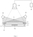
- FIG. 1 is a side view illustrating an inspection apparatus for an electrode assembly according to an embodiment of the present invention
- FIG. 2 is a plan view of only the electrode assembly of FIG. 1 .
- an inspection apparatus for an electrode assembly relates to an alignment inspection apparatus for an electrode assembly 10 including a laminate in which a separator 11, an internal electrode 13, a separator 11, and an upper electrode 15 are sequentially laminated.
- the inspection apparatus for the electrode assembly according to an embodiment of the present invention includes a camera unit disposed above a central portion of the electrode assembly 10 to photograph and inspect the electrode assembly 10 and side lighting units 30 that obliquely irradiate light onto both ends of the upper electrode 15, which are symmetrical to each other with respect to a central portion of the electrode assembly 10.
- the electrode assembly 10 may be a mono cell.
- the internal electrode 13 may be a positive electrode
- the upper electrode 15 may be a negative electrode having an opposite polarity to the internal electrode 13.
- the upper electrode 15 is the negative electrode having an opposite polarity to the internal electrode.
- the internal electrode 13 is disposed between the separators 11 in the form of a sandwich in which the separators are laminated on top and bottom surfaces of the internal electrode 13. Also, since each of the separators 11 has a size greater than that of the internal electrode 13, the internal electrode 13 is completely covered by the separators disposed on the top and bottom surfaces of the internal electrode 13 when viewed in the plan view of FIG. 2 .
- the upper electrode 15 may have a size less than that of the internal electrode 13.
- An electrode tab extending from each of opposite ends of the internal electrode 13 and the upper electrode 15 may be formed on each of the ends.
- the camera unit 20 is installed above a central portion of the electrode assembly 10 so as to be spaced a predetermined distance from the electrode assembly 10 to photograph the electrode assembly 10 from an upper side of the central portion of the electrode assembly 10.
- the two side lighting units 30 are installed above each of both ends of the electrode assembly 10 so as to be spaced upward from th electrode assembly 10.
- a spaced distance between the side lighting units 30 and the electrode assembly 10 is less than that between the camera unit 20 and the electrode assembly 10.
- the reason for which the camera unit 20 is installed to have a longer distance from the electrode assembly 10 than the side lighting units 30 is for photographing the entire shape of the electrode assembly 10.
- the two side lighting units 30 are provided on the ends of the electrode assembly, on which the electrode tab is not formed, of the ends of the electrode assembly 10 so that the pair of side lighting units 30 are symmetrical to each other with respect to the central portion of the electrode assembly 10.
- the side lighting units 30 obliquely irradiate light toward both the ends of the upper electrode 15 at a predetermined angle.
- the side lighting units 30 may be spaced a predetermined distance from the electrode assembly 10 so as to be symmetrical to each other with respect to the central portion of the electrode assembly 10, thereby obliquely irradiating light onto both the ends of the upper electrode 15.
- the light may be irradiated onto an area A of the electrode assembly 10, on which the light irradiated from the pair of side lighting units 30 overlap each other.
- the shaded portion by the irradiation may be removed on the electrode assembly 10 photographed by the camera that disposed above the central portion to photograph the electrode assembly to maximize brightness of the lighting that irradiates the electrode assembly 10.
- the camera unit 20 may photograph the electrode assembly 10 to transmit photographed image information to a control unit 50.
- control unit 50 may be a central processing unit (CPU).
- the control unit 50 may measure a length d1 between one end of a tab 13a of the internal electrode 13 and one end of the upper electrode 15 of the electrode assembly 10 from the image information transmitted from the camera unit 20. An alignment state between the upper electrode 15 and the internal electrode 13 may be inspected through the measured value.
- the tab 13a of the internal electrode is a component that is attached to the internal electrode 13, when the internal electrode moves, the tab 13a of the internal electrode may also move. Thus, a position of the internal electrode 13 may be grasped through a position of the tab 13a of the internal electrode.
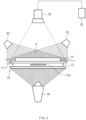
- FIG. 3 is a side view illustrating an inspection apparatus for an electrode assembly not covered by the claims of the present patent
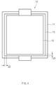
- FIG. 4 is a plan view of only the electrode assembly of FIG. 3 .
- an inspection apparatus for an electrode assembly not covered by the claims of the present invention includes a low lighting unit 40 that is installed below the electrode assembly 10 to irradiate light to a bottom surface of the electrode assembly 10.
- the low lighting unit 40 irradiates light to a separator 11 that forms the bottom surface of the electrode assembly 10 to project the internal electrode 13 laminated in the form of a sandwich between the two separators 11 to the separator 11.
- a boundary line of the internal electrode, which is hidden by the separator, may be seen on an upper surface of the separator due to the lower lighting unit 40.
- the camera unit 20 photographs the electrode assembly 10 from an upper side of a central portion of the electrode assembly 10 to transmit photographed image information to the control unit 50, and the control unit 50 measures a distance d2 between one end of the internal electrode 13 and one end of the upper electrode 15 on the basis of the transmitted image information.
- the distance d2 is a distance that is measured in a width direction.
- a distance d3 is measured in a length direction.
- An alignment state between the upper electrode 15 and the internal electrode 13 is inspected through the measured value.
- the distances may be more precisely measured when compared to the measurement through the internal electrode tab 13a according to an embodiment.
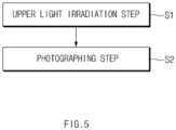
- FIG. 5 is a flowchart sequentially illustrating an inspection method for an electrode assembly according to an embodiment of the present invention.
- an inspection method for an electrode assembly includes an upper light irradiation step (S1) and a photographing step (S2).
- the upper light irradiation step (S1) is a step of irradiating light by using the side lighting units 30 installed to be spaced upward from the electrode assembly 10. Particularly, the upper light irradiation step (S1) is a step of installing each of the side lighting units 30 on another end, which are symmetrical to each other with respect to a central portion of the electrode assembly 10, to obliquely irradiate light to both ends of the upper electrode 15.
- the photographing step (S2) is a step of photographing the electrode assembly 10 through a camera unit 20 disposed above the central portion of the electrode assembly 10 when light of the side lighting units 30 is irradiated onto the electrode assembly 10 in the upper light irradiation step (S1).
- the inspection method may further include a measurement step of transmitting information of an image photographed by the camera unit 20 to a control unit 50 in the photographing step (S2) and allowing the control unit 50 to measure a distance d1 between one end of a tab 13a of an internal electrode and one end of an upper electrode 15 from the image information transmitted from the camera unit 20.
- FIG. 6 is a flowchart sequentially illustrating an inspection method for an electrode assembly according to another embodiment of the present invention.
- an inspection method for an electrode assembly not covered by the claims of the present patent includes an upper light irradiation step (S1), a lower light irradiation step (S1-1), and a photographing step (S2).
- the upper light irradiation step (S1) is a step of irradiating light by using the side lighting units 30 installed to be spaced upward from the electrode assembly 10. Particularly, the upper light irradiation step (S1) is a step of installing each of the side lighting unit 30 on another end, which are symmetrical to each other with respect to a central portion of the electrode assembly 10, to obliquely irradiate light to both ends of the upper electrode 15.
- the lower light irradiation step (S1-1) is a step of irradiating light onto a bottom surface of the electrode assembly 10 by using the lower lighting unit 40 installed below the central portion of the electrode assembly 10.
- the photographing step (S2) is a step of photographing the electrode assembly 10 by using a camera unit 20 disposed above the central portion of the electrode assembly 10 when light of the side lighting units 30 is irradiated onto the electrode assembly 10 in the upper light irradiation step (S1), and light of the lower lighting unit 40 is irradiated onto a bottom surface of the electrode assembly 10 in the lower light irradiation step (S1-1) so that an internal electrode 13 is projected to a separator 11.
- the inspection method may further include a measurement step of transmitting information of an image photographed by the camera unit 20 to a control unit 50 in the photographing step (S2) and allowing the control unit 50 to measure a distance d2 between one end of the internal electrode 13, which is projected to the separator 11, and one end of the upper electrode 15 from the image information transmitted from the camera unit 20.
- the alignment inspection of the internal electrode of the mono cell may be enabled by using the distance between the internal electrode tab and the upper electrode.
Description
- This application claims the priority of
Korean Patent Application No. 10-2018-0036851, filed on March 29, 2018 - The present invention relates to an alignment inspection apparatus for an electrode assembly and an alignment inspection method, and more particularly, to an alignment inspection apparatus for an electrode assembly, which inspects alignment quality of an internal electrode laminated in the form of a sandwich between separators in a mono cell, and an align inspection method for an electrode assembly using the same.
- Batteries (cells) that generate electric energy through physical or chemical reaction to supply the generated electric energy to the outside are used when AC power to be supplied to the building is not obtained, or DC power is required according to the living environments surrounded by various electric and electronic devices.
- Among such batteries, primary batteries and secondary batteries, which are chemical batteries using chemical reaction, are being generally used. The primary batteries are consumable batteries which are collectively referred to as dry batteries. Also, secondary batteries are rechargeable batteries that are manufactured by using a material in a redox process between current and a substance is repeatable several times. When the reduction reaction is performed on the material by the current, power is charged, and when the oxidation reaction is performed on the material, power is discharged. Such the charging-discharging is repeatedly performed to generate electricity.
- A lithium ion battery of the secondary batteries is manufactured through the following processes. An active material is applied to each of a positive electrode conductive foil and a negative electrode conductive foil at a predetermined thickness, and a separator is disposed between the positive electrode conductive foil and the negative electrode conductive foil, and then, an electrode assembly, in which the positive electrode conductive foil, the separator, and the negative electrode conductive foil are wound several times in a jelly-roll or cylindrical shape, is accommodated into a cylindrical or prismatic can, a pouch, and the like to seal the resultant product, thereby manufacturing the lithium ion battery.
- An electrode assembly according to the related art is disclosed in
Korean Patent Publication No. 10-2017-0057778 - There is a method, in which mono cells are produced to be laminated so as to manufacture a finished cell, as one method for manufacturing an electrode assembly according to the related art.
- In the mono cell, the two outermost electrodes have polarities different from each other. When the plurality of electrodes are laminated with a separator therebetween, there is a problem in that it is difficult to inspect alignment quality of the internal electrode disposed at an intermediate layer because the separator is laminated on each of top and bottom surfaces of the internal electrode.
- Further prior art is described in
JP 2010 257861 A JP 2015 176699 A - Therefore, the present invention has been made to solve the abovementioned problem, and an object of the prevent invention is to provide an alignment inspection apparatus for an electrode assembly, which inspects alignment quality of a mono cell, and an alignment inspection method for an electrode assembly using the same.
- An alignment inspection apparatus for an electrode assembly including a laminate, in which a separator, an internal electrode, a separator, and an upper electrode are sequentially laminated, according to an embodiment of the present invention includes a camera unit configured to be disposed above a central portion of the electrode assembly to photograph and inspect the electrode assembly, two side lighting units installed so as to be spaced a predetermined distance from the electrode assembly and configured to obliquely irradiate light onto each of both ends of the upper electrode, which are symmetrical to each other with respect to the central portion of the electrode assembly, and further includes a control unit configured to measure an alignment state of the electrode assembly through photographed information of the electrode assembly observed through the camera unit, wherein the control unit is configured to measure a distance between one end of a tab arranged at the internal electrode and one end of the upper electrode of the electrode assembly.
- According to an embodiment of the present invention an alignment inspection method for an electrode assembly through the alignment inspection apparatus of
claim 1, the electrode assembly comprising a laminate in which a separator, an internal electrode, a separator, and an upper electrode are sequentially laminated, includes an upper light irradiation step of obliquely irradiating light onto each of both ends of the electrode assembly, which are symmetrical to each other with respect to a central portion of the electrode assembly, by using the side lighting units and a photographing step of photographing the electrode assembly through the camera unit disposed above the central portion of the electrode assembly and further includes a measurement step of transmitting information observed through the camera unit to the control unit and measuring a distance between one end of an internal electrode tab and one end of an upper electrode through the control unit. - According to the present invention, the alignment inspection of the internal electrode of the mono cell may be enabled by using the distance between the internal electrode tab and the upper electrode.
- According to the present invention, the lighting is illuminated onto each of both ends of the surface of the mono cell to measure the distance between the ends of the internal electrode and the upper electrode, thereby performing the alignment inspection of the internal electrode.
-
-
FIG. 1 is a side view illustrating an inspection apparatus for an electrode assembly according to an embodiment of the present invention. -
FIG. 2 is a plan view of only the electrode assembly ofFIG. 1 . -
FIG. 3 is a side view of an inspection apparatus for an electrode assembly not covered by the claims of the present patent. -
FIG. 4 is a plan view of only the electrode assembly ofFIG. 3 . -
FIG. 5 is a flowchart sequentially illustrating an inspection method for an electrode assembly according to an embodiment of the present invention. -
FIG. 6 is a flowchart sequentially illustrating an inspection method for an electrode assembly not covered by the claims of the present patent. - Hereinafter, an alignment inspection apparatus for an electrode assembly according to a preferred embodiment of the present invention will be described in detail with reference to the accompanying drawings.
- Terms or words used in the specification and claims should not be construed as limited to a lexical meaning, and should be understood as appropriate notions by the inventor based on that he/she is able to define terms to describe his/her invention in the best way to be seen by others. Therefore, embodiments and drawings described herein are simply exemplary and not exhaustive, and it will be understood that various equivalents may be made to take the place of the embodiments.
- In the drawings, the dimension of each of components or a specific portion constituting the component is exaggerated, omitted, or schematically illustrated for convenience in description and clarity. Thus, the dimension of each element does not entirely reflect an actual size. Moreover, detailed descriptions related to well-known functions or configurations will be ruled out in order not to unnecessarily obscure subject matters of the present invention.
-
FIG. 1 is a side view illustrating an inspection apparatus for an electrode assembly according to an embodiment of the present invention, andFIG. 2 is a plan view of only the electrode assembly ofFIG. 1 . - As illustrated in
FIGS. 1 to 2 , an inspection apparatus for an electrode assembly according to an embodiment of the present invention relates to an alignment inspection apparatus for anelectrode assembly 10 including a laminate in which aseparator 11, aninternal electrode 13, aseparator 11, and anupper electrode 15 are sequentially laminated. The inspection apparatus for the electrode assembly according to an embodiment of the present invention includes a camera unit disposed above a central portion of theelectrode assembly 10 to photograph and inspect theelectrode assembly 10 andside lighting units 30 that obliquely irradiate light onto both ends of theupper electrode 15, which are symmetrical to each other with respect to a central portion of theelectrode assembly 10. - The
electrode assembly 10 may be a mono cell. Theinternal electrode 13 may be a positive electrode, and theupper electrode 15 may be a negative electrode having an opposite polarity to theinternal electrode 13. When theinternal electrode 13 is the positive electrode, theupper electrode 15 is the negative electrode having an opposite polarity to the internal electrode. - The
internal electrode 13 is disposed between theseparators 11 in the form of a sandwich in which the separators are laminated on top and bottom surfaces of theinternal electrode 13. Also, since each of theseparators 11 has a size greater than that of theinternal electrode 13, theinternal electrode 13 is completely covered by the separators disposed on the top and bottom surfaces of theinternal electrode 13 when viewed in the plan view ofFIG. 2 . - The
upper electrode 15 may have a size less than that of theinternal electrode 13. - An electrode tab extending from each of opposite ends of the
internal electrode 13 and theupper electrode 15 may be formed on each of the ends. - The
camera unit 20 is installed above a central portion of theelectrode assembly 10 so as to be spaced a predetermined distance from theelectrode assembly 10 to photograph theelectrode assembly 10 from an upper side of the central portion of theelectrode assembly 10. - The two
side lighting units 30 are installed above each of both ends of theelectrode assembly 10 so as to be spaced upward from thelectrode assembly 10. A spaced distance between theside lighting units 30 and theelectrode assembly 10 is less than that between thecamera unit 20 and theelectrode assembly 10. The reason for which thecamera unit 20 is installed to have a longer distance from theelectrode assembly 10 than theside lighting units 30 is for photographing the entire shape of theelectrode assembly 10. - The two
side lighting units 30 are provided on the ends of the electrode assembly, on which the electrode tab is not formed, of the ends of theelectrode assembly 10 so that the pair ofside lighting units 30 are symmetrical to each other with respect to the central portion of theelectrode assembly 10. Thus, theside lighting units 30 obliquely irradiate light toward both the ends of theupper electrode 15 at a predetermined angle. - The
side lighting units 30 may be spaced a predetermined distance from theelectrode assembly 10 so as to be symmetrical to each other with respect to the central portion of theelectrode assembly 10, thereby obliquely irradiating light onto both the ends of theupper electrode 15. Thus, the light may be irradiated onto an area A of theelectrode assembly 10, on which the light irradiated from the pair ofside lighting units 30 overlap each other. As a result, the shaded portion by the irradiation may be removed on theelectrode assembly 10 photographed by the camera that disposed above the central portion to photograph the electrode assembly to maximize brightness of the lighting that irradiates theelectrode assembly 10. - The
camera unit 20 may photograph theelectrode assembly 10 to transmit photographed image information to acontrol unit 50. - For example, the
control unit 50 may be a central processing unit (CPU). Thecontrol unit 50 may measure a length d1 between one end of atab 13a of theinternal electrode 13 and one end of theupper electrode 15 of theelectrode assembly 10 from the image information transmitted from thecamera unit 20. An alignment state between theupper electrode 15 and theinternal electrode 13 may be inspected through the measured value. - Since the
tab 13a of the internal electrode is a component that is attached to theinternal electrode 13, when the internal electrode moves, thetab 13a of the internal electrode may also move. Thus, a position of theinternal electrode 13 may be grasped through a position of thetab 13a of the internal electrode. -
FIG. 3 is a side view illustrating an inspection apparatus for an electrode assembly not covered by the claims of the present patent, andFIG. 4 is a plan view of only the electrode assembly ofFIG. 3 . - Referring to
FIGS. 3 and4 , an inspection apparatus for an electrode assembly not covered by the claims of the present invention includes alow lighting unit 40 that is installed below theelectrode assembly 10 to irradiate light to a bottom surface of theelectrode assembly 10. - The
low lighting unit 40 irradiates light to aseparator 11 that forms the bottom surface of theelectrode assembly 10 to project theinternal electrode 13 laminated in the form of a sandwich between the twoseparators 11 to theseparator 11. A boundary line of the internal electrode, which is hidden by the separator, may be seen on an upper surface of the separator due to thelower lighting unit 40. - Here, the
camera unit 20 photographs theelectrode assembly 10 from an upper side of a central portion of theelectrode assembly 10 to transmit photographed image information to thecontrol unit 50, and thecontrol unit 50 measures a distance d2 between one end of theinternal electrode 13 and one end of theupper electrode 15 on the basis of the transmitted image information. The distance d2 is a distance that is measured in a width direction. Also, a distance d3 is measured in a length direction. - An alignment state between the
upper electrode 15 and theinternal electrode 13 is inspected through the measured value. When the distances are measured through the above-described manner, the distances may be more precisely measured when compared to the measurement through theinternal electrode tab 13a according to an embodiment. - Hereinafter, an inspection method for an electrode assembly will be described in detail with reference to the accompanying drawings.
-
FIG. 5 is a flowchart sequentially illustrating an inspection method for an electrode assembly according to an embodiment of the present invention. - As illustrated in
FIG. 5 , an inspection method for an electrode assembly according to an embodiment of the present invention includes an upper light irradiation step (S1) and a photographing step (S2). - The upper light irradiation step (S1) is a step of irradiating light by using the
side lighting units 30 installed to be spaced upward from theelectrode assembly 10. Particularly, the upper light irradiation step (S1) is a step of installing each of theside lighting units 30 on another end, which are symmetrical to each other with respect to a central portion of theelectrode assembly 10, to obliquely irradiate light to both ends of theupper electrode 15. - The photographing step (S2) is a step of photographing the
electrode assembly 10 through acamera unit 20 disposed above the central portion of theelectrode assembly 10 when light of theside lighting units 30 is irradiated onto theelectrode assembly 10 in the upper light irradiation step (S1). - The inspection method may further include a measurement step of transmitting information of an image photographed by the
camera unit 20 to acontrol unit 50 in the photographing step (S2) and allowing thecontrol unit 50 to measure a distance d1 between one end of atab 13a of an internal electrode and one end of anupper electrode 15 from the image information transmitted from thecamera unit 20. -
FIG. 6 is a flowchart sequentially illustrating an inspection method for an electrode assembly according to another embodiment of the present invention. - As illustrated in
FIG. 6 , an inspection method for an electrode assembly not covered by the claims of the present patent includes an upper light irradiation step (S1), a lower light irradiation step (S1-1), and a photographing step (S2). - The upper light irradiation step (S1) is a step of irradiating light by using the
side lighting units 30 installed to be spaced upward from theelectrode assembly 10. Particularly, the upper light irradiation step (S1) is a step of installing each of theside lighting unit 30 on another end, which are symmetrical to each other with respect to a central portion of theelectrode assembly 10, to obliquely irradiate light to both ends of theupper electrode 15. - The lower light irradiation step (S1-1) is a step of irradiating light onto a bottom surface of the
electrode assembly 10 by using thelower lighting unit 40 installed below the central portion of theelectrode assembly 10. - The photographing step (S2) is a step of photographing the
electrode assembly 10 by using acamera unit 20 disposed above the central portion of theelectrode assembly 10 when light of theside lighting units 30 is irradiated onto theelectrode assembly 10 in the upper light irradiation step (S1), and light of thelower lighting unit 40 is irradiated onto a bottom surface of theelectrode assembly 10 in the lower light irradiation step (S1-1) so that aninternal electrode 13 is projected to aseparator 11. - The inspection method may further include a measurement step of transmitting information of an image photographed by the
camera unit 20 to acontrol unit 50 in the photographing step (S2) and allowing thecontrol unit 50 to measure a distance d2 between one end of theinternal electrode 13, which is projected to theseparator 11, and one end of theupper electrode 15 from the image information transmitted from thecamera unit 20. - As described above, according to an embodiment of the present invention, the alignment inspection of the internal electrode of the mono cell may be enabled by using the distance between the internal electrode tab and the upper electrode.
Claims (2)
- An alignment inspection apparatus for an electrode assembly (10) comprising a laminate in which a separator (11), an internal electrode (13), a separator (11), and an upper electrode (15) are sequentially laminated, the alignment inspection apparatus comprising:a camera unit (20) configured to be disposed above a central portion of the electrode assembly (10) to photograph and inspect the electrode assembly (10);two side lighting units (30) installed so as to be spaced a predetermined distance from the electrode assembly (10), and configured to obliquely irradiate light onto each of both ends of the upper electrode (15), which are symmetrical to each other with respect to the central portion of the electrode assembly (10); anda control unit (50) configured to measure an alignment state of the electrode assembly (10) through photographed information of the electrode assembly (10) observed through the camera unit (20),wherein the control unit (50) is configured to measure a distance between one end of a tab (13a) arranged at the internal electrode and one end of the upper electrode (15) of the electrode assembly (10).
- An alignment inspection method for an electrode assembly (10) through the alignment inspection apparatus of claim 1, the electrode assembly (10) comprising a laminate in which a separator (11), an internal electrode (13), a separator (11), and an upper electrode (15) are sequentially laminated, the alignment inspection method comprising:an upper light irradiation step (S1) of obliquely irradiating light onto each of both ends of the electrode assembly (10), which are symmetrical to each other with respect to a central portion of the electrode assembly (10), by using the side lighting units (30);a photographing step (S2) of photographing the electrode assembly (10) through the camera unit (20) disposed above the central portion of the electrode assembly (10); anda measurement step of transmitting information observed through the camera unit (20) to the control unit (50) and measuring a distance between one end of a tab (13a) of an internal electrode and one end of an upper electrode (15) through the control unit (50).
Applications Claiming Priority (2)
| Application Number | Priority Date | Filing Date | Title |
|---|---|---|---|
| KR1020180036851A KR102217201B1 (en) | 2018-03-29 | 2018-03-29 | Apparatus for inspecting alignment of electrode assembly and method of inspecting electrode assembly using the same |
| PCT/KR2019/003406 WO2019190129A1 (en) | 2018-03-29 | 2019-03-22 | Electrode assembly alignment inspection device and electrode assembly alignment inspection method using same |
Publications (3)
| Publication Number | Publication Date |
|---|---|
| EP3627143A1 EP3627143A1 (en) | 2020-03-25 |
| EP3627143A4 EP3627143A4 (en) | 2020-10-21 |
| EP3627143B1 true EP3627143B1 (en) | 2023-06-14 |
Family
ID=68060629
Family Applications (1)
| Application Number | Title | Priority Date | Filing Date |
|---|---|---|---|
| EP19777062.1A Active EP3627143B1 (en) | 2018-03-29 | 2019-03-22 | Alignment inspection apparatus for electrode assembly and alignment inspection method for electrode assembly using the same |
Country Status (8)
| Country | Link |
|---|---|
| US (2) | US11307026B2 (en) |
| EP (1) | EP3627143B1 (en) |
| KR (1) | KR102217201B1 (en) |
| CN (1) | CN110832308B (en) |
| ES (1) | ES2949018T3 (en) |
| HU (1) | HUE062100T2 (en) |
| PL (1) | PL3627143T3 (en) |
| WO (1) | WO2019190129A1 (en) |
Families Citing this family (13)
| Publication number | Priority date | Publication date | Assignee | Title |
|---|---|---|---|---|
| KR102629119B1 (en) * | 2018-05-02 | 2024-01-26 | 에스케이온 주식회사 | Electrode plate position inspection system and inspection method |
| DE102020104668A1 (en) | 2020-02-21 | 2021-08-26 | Volkswagen Aktiengesellschaft | Battery electrode inspection system |
| KR102343421B1 (en) | 2020-04-25 | 2021-12-27 | 주식회사 클레버 | Device for aligning pouch type secondary battery |
| JPWO2021230245A1 (en) * | 2020-05-11 | 2021-11-18 | ||
| CN112018453B (en) * | 2020-09-08 | 2022-02-01 | 深圳吉阳智能科技有限公司 | Composite laminated battery cell manufacturing control method, composite laminated battery cell and lithium battery |
| CN112249795B (en) * | 2020-10-19 | 2021-10-29 | 广东利元亨智能装备股份有限公司 | Real-time correction method and device for rubberizing process, electronic equipment and readable storage medium |
| KR102569188B1 (en) * | 2020-12-29 | 2023-08-21 | 안보혁 | An apparatus for inspecting secondary battery and the inspection method |
| KR20220114978A (en) | 2021-02-09 | 2022-08-17 | 주식회사 클레버 | Vacuum absorbtion auxiliary device for pouch type secondary battery |
| KR102478650B1 (en) | 2021-02-09 | 2022-12-19 | 주식회사 클레버 | Device for aligning pouch type secondary battery |
| KR102413822B1 (en) | 2021-03-02 | 2022-06-29 | 주식회사 클레버 | Hot press device for folding surface of pouch type secondary battery |
| KR102375302B1 (en) | 2021-03-09 | 2022-03-17 | 주식회사 클레버 | Hot press system for folding surface of pouch type secondary battery |
| KR20240042524A (en) * | 2022-04-12 | 2024-04-02 | 컨템포러리 엠퍼렉스 테크놀로지 씨오., 리미티드 | Method and device for detection of material strip feeding for laminators, laminators, devices and media |
| KR20240041226A (en) * | 2022-09-22 | 2024-03-29 | 주식회사 엘지화학 | Measurement apparatus and method of thermal shrinkage ratio of a separator |
Family Cites Families (17)
| Publication number | Priority date | Publication date | Assignee | Title |
|---|---|---|---|---|
| KR100315117B1 (en) * | 1999-09-30 | 2001-11-24 | 김순택 | Glass Alignment Inspection System |
| KR100841662B1 (en) * | 2006-06-23 | 2008-06-26 | 주식회사 고영테크놀러지 | System and Method for Measuring Three Dimension Shape Using Moire and Stereo |
| KR101190122B1 (en) * | 2008-10-13 | 2012-10-11 | 주식회사 고영테크놀러지 | Apparatus and method for measuring three dimension shape using multi-wavelength |
| KR101015808B1 (en) * | 2009-03-27 | 2011-02-22 | 한국영상기술(주) | Apparatus and method for measuring line width of bonding electrode |
| JP5438368B2 (en) * | 2009-04-28 | 2014-03-12 | Ckd株式会社 | Inspection equipment used in the manufacturing process of laminated batteries |
| KR101334121B1 (en) | 2009-10-26 | 2013-11-29 | 에스케이이노베이션 주식회사 | Electrode Inspection Device for Battery and Method of the Same. |
| JP6022177B2 (en) * | 2011-04-07 | 2016-11-09 | 日産自動車株式会社 | Electrode position detection device and electrode position detection method |
| JP2013161580A (en) | 2012-02-02 | 2013-08-19 | Toyota Motor Corp | Electrode substrate checking method |
| JP5988474B2 (en) | 2012-03-01 | 2016-09-07 | 東レエンジニアリング株式会社 | Equipment for inspecting the end face of laminated sheet material |
| JP5696076B2 (en) * | 2012-03-21 | 2015-04-08 | 株式会社東芝 | Semiconductor device inspection apparatus and semiconductor device inspection method |
| KR101609425B1 (en) * | 2013-09-26 | 2016-04-05 | 주식회사 엘지화학 | Method of manufacturing electrode assembly using magazine |
| JP6237362B2 (en) * | 2014-03-14 | 2017-11-29 | 株式会社豊田自動織機 | Sheet stacking device |
| KR101956348B1 (en) | 2015-01-13 | 2019-03-08 | 에리 파워 가부시키가이샤 | Method and apparatus for detecting displacement of electrode plate in electrode laminate |
| KR102079233B1 (en) | 2015-11-17 | 2020-02-19 | 주식회사 엘지화학 | Electrode assembly |
| KR101730469B1 (en) * | 2015-12-21 | 2017-04-27 | 주식회사 디에이테크놀로지 | Apparatus for Manufacturing Cell Stack for Secondary Battery |
| CN105929460A (en) * | 2016-05-07 | 2016-09-07 | 合肥国轩高科动力能源有限公司 | Electrode subassembly alignment detection apparatus and detection method thereof |
| US10346969B1 (en) * | 2018-01-02 | 2019-07-09 | Amazon Technologies, Inc. | Detecting surface flaws using computer vision |
-
2018
- 2018-03-29 KR KR1020180036851A patent/KR102217201B1/en active IP Right Grant
-
2019
- 2019-03-22 PL PL19777062.1T patent/PL3627143T3/en unknown
- 2019-03-22 WO PCT/KR2019/003406 patent/WO2019190129A1/en unknown
- 2019-03-22 HU HUE19777062A patent/HUE062100T2/en unknown
- 2019-03-22 US US16/636,244 patent/US11307026B2/en active Active
- 2019-03-22 EP EP19777062.1A patent/EP3627143B1/en active Active
- 2019-03-22 CN CN201980003295.9A patent/CN110832308B/en active Active
- 2019-03-22 ES ES19777062T patent/ES2949018T3/en active Active
-
2022
- 2022-03-22 US US17/701,418 patent/US11781859B2/en active Active
Also Published As
| Publication number | Publication date |
|---|---|
| US11307026B2 (en) | 2022-04-19 |
| CN110832308A (en) | 2020-02-21 |
| KR102217201B1 (en) | 2021-02-18 |
| HUE062100T2 (en) | 2023-09-28 |
| CN110832308B (en) | 2023-04-11 |
| WO2019190129A1 (en) | 2019-10-03 |
| US20200370882A1 (en) | 2020-11-26 |
| US20220214164A1 (en) | 2022-07-07 |
| PL3627143T3 (en) | 2023-10-02 |
| ES2949018T3 (en) | 2023-09-25 |
| EP3627143A1 (en) | 2020-03-25 |
| US11781859B2 (en) | 2023-10-10 |
| EP3627143A4 (en) | 2020-10-21 |
| KR20190114322A (en) | 2019-10-10 |
Similar Documents
| Publication | Publication Date | Title |
|---|---|---|
| EP3627143B1 (en) | Alignment inspection apparatus for electrode assembly and alignment inspection method for electrode assembly using the same | |
| US11296326B2 (en) | Energy storage device and method for manufacturing the same | |
| TWI660536B (en) | Method for detecting the positional deviation of electrode plate in an electrode stacked body and device therefor | |
| KR101676407B1 (en) | Test method for thermal pad and method of fabricating battery module using the same | |
| EP3001493A1 (en) | Electrode assembly production method | |
| KR20150061825A (en) | Inspection Device for Secondary Battery Unit Cell | |
| CN111566862B (en) | Method of manufacturing electrode assembly and method of manufacturing secondary battery | |
| KR20150089448A (en) | Electrode assembly having partly folded function and battery cell including the same | |
| EP3840098B1 (en) | Electrode assembly and inspection method therefor | |
| EP4027424A1 (en) | Apparatus for inspecting stacking of electrodes of secondary battery and inspection method thereof | |
| KR20210025404A (en) | Thickness measurement apparatus and thickness measurement apparatus for unit cell | |
| KR20170093377A (en) | Device for Welding Electrode Tabs Comprising Vision Inspection Part | |
| JP2002198097A (en) | Method for inspecting cell | |
| JP6819449B2 (en) | Inspection method of power storage device | |
| US10777853B2 (en) | Apparatus for measuring variation in thickness of electrode of secondary battery and secondary battery with the same mounted therein | |
| KR102055721B1 (en) | Thickness measurement device for electrode assembly and thickness measurement method for electrode assembly | |
| KR102537425B1 (en) | Stacked electrode body, resin-fixed stacked electrode body, and all-solid-state battery | |
| KR20230013863A (en) | Electrode laminate heating unit and lamination device including the same | |
| KR101821454B1 (en) | Apparatus for leakage test of secondary battery | |
| KR20220010167A (en) | Electrode assembly manufacturing equipment and mauufacturing method of electrode assembly | |
| KR20230047817A (en) | Apparatus for measuring of electrode camber | |
| JP2019008977A (en) | Welding inspection method for power storage device | |
| JP2017016735A (en) | Manufacturing apparatus of thickness adjustment film, and manufacturing method of thickness adjustment film |
Legal Events
| Date | Code | Title | Description |
|---|---|---|---|
| STAA | Information on the status of an ep patent application or granted ep patent |
Free format text: STATUS: THE INTERNATIONAL PUBLICATION HAS BEEN MADE |
|
| PUAI | Public reference made under article 153(3) epc to a published international application that has entered the european phase |
Free format text: ORIGINAL CODE: 0009012 |
|
| STAA | Information on the status of an ep patent application or granted ep patent |
Free format text: STATUS: REQUEST FOR EXAMINATION WAS MADE |
|
| 17P | Request for examination filed |
Effective date: 20191220 |
|
| AK | Designated contracting states |
Kind code of ref document: A1 Designated state(s): AL AT BE BG CH CY CZ DE DK EE ES FI FR GB GR HR HU IE IS IT LI LT LU LV MC MK MT NL NO PL PT RO RS SE SI SK SM TR |
|
| AX | Request for extension of the european patent |
Extension state: BA ME |
|
| A4 | Supplementary search report drawn up and despatched |
Effective date: 20200921 |
|
| RIC1 | Information provided on ipc code assigned before grant |
Ipc: G01N 21/88 20060101AFI20200915BHEP Ipc: H01M 10/04 20060101ALI20200915BHEP |
|
| STAA | Information on the status of an ep patent application or granted ep patent |
Free format text: STATUS: EXAMINATION IS IN PROGRESS |
|
| 17Q | First examination report despatched |
Effective date: 20210421 |
|
| DAV | Request for validation of the european patent (deleted) | ||
| DAX | Request for extension of the european patent (deleted) | ||
| RAP1 | Party data changed (applicant data changed or rights of an application transferred) |
Owner name: LG ENERGY SOLUTION LTD. |
|
| RAP3 | Party data changed (applicant data changed or rights of an application transferred) |
Owner name: LG ENERGY SOLUTION, LTD. |
|
| GRAP | Despatch of communication of intention to grant a patent |
Free format text: ORIGINAL CODE: EPIDOSNIGR1 |
|
| STAA | Information on the status of an ep patent application or granted ep patent |
Free format text: STATUS: GRANT OF PATENT IS INTENDED |
|
| INTG | Intention to grant announced |
Effective date: 20230216 |
|
| GRAS | Grant fee paid |
Free format text: ORIGINAL CODE: EPIDOSNIGR3 |
|
| GRAA | (expected) grant |
Free format text: ORIGINAL CODE: 0009210 |
|
| STAA | Information on the status of an ep patent application or granted ep patent |
Free format text: STATUS: THE PATENT HAS BEEN GRANTED |
|
| AK | Designated contracting states |
Kind code of ref document: B1 Designated state(s): AL AT BE BG CH CY CZ DE DK EE ES FI FR GB GR HR HU IE IS IT LI LT LU LV MC MK MT NL NO PL PT RO RS SE SI SK SM TR |
|
| REG | Reference to a national code |
Ref country code: CH Ref legal event code: EP |
|
| P01 | Opt-out of the competence of the unified patent court (upc) registered |
Effective date: 20230516 |
|
| REG | Reference to a national code |
Ref country code: DE Ref legal event code: R096 Ref document number: 602019031093 Country of ref document: DE |
|
| REG | Reference to a national code |
Ref country code: AT Ref legal event code: REF Ref document number: 1579576 Country of ref document: AT Kind code of ref document: T Effective date: 20230715 |
|
| REG | Reference to a national code |
Ref country code: SE Ref legal event code: TRGR |
|
| REG | Reference to a national code |
Ref country code: ES Ref legal event code: FG2A Ref document number: 2949018 Country of ref document: ES Kind code of ref document: T3 Effective date: 20230925 |
|
| REG | Reference to a national code |
Ref country code: HU Ref legal event code: AG4A Ref document number: E062100 Country of ref document: HU |
|
| REG | Reference to a national code |
Ref country code: LT Ref legal event code: MG9D |
|
| REG | Reference to a national code |
Ref country code: NL Ref legal event code: MP Effective date: 20230614 |
|
| PG25 | Lapsed in a contracting state [announced via postgrant information from national office to epo] |
Ref country code: NO Free format text: LAPSE BECAUSE OF FAILURE TO SUBMIT A TRANSLATION OF THE DESCRIPTION OR TO PAY THE FEE WITHIN THE PRESCRIBED TIME-LIMIT Effective date: 20230914 |
|
| REG | Reference to a national code |
Ref country code: AT Ref legal event code: MK05 Ref document number: 1579576 Country of ref document: AT Kind code of ref document: T Effective date: 20230614 |
|
| PG25 | Lapsed in a contracting state [announced via postgrant information from national office to epo] |
Ref country code: RS Free format text: LAPSE BECAUSE OF FAILURE TO SUBMIT A TRANSLATION OF THE DESCRIPTION OR TO PAY THE FEE WITHIN THE PRESCRIBED TIME-LIMIT Effective date: 20230614 Ref country code: NL Free format text: LAPSE BECAUSE OF FAILURE TO SUBMIT A TRANSLATION OF THE DESCRIPTION OR TO PAY THE FEE WITHIN THE PRESCRIBED TIME-LIMIT Effective date: 20230614 Ref country code: LV Free format text: LAPSE BECAUSE OF FAILURE TO SUBMIT A TRANSLATION OF THE DESCRIPTION OR TO PAY THE FEE WITHIN THE PRESCRIBED TIME-LIMIT Effective date: 20230614 Ref country code: LT Free format text: LAPSE BECAUSE OF FAILURE TO SUBMIT A TRANSLATION OF THE DESCRIPTION OR TO PAY THE FEE WITHIN THE PRESCRIBED TIME-LIMIT Effective date: 20230614 Ref country code: HR Free format text: LAPSE BECAUSE OF FAILURE TO SUBMIT A TRANSLATION OF THE DESCRIPTION OR TO PAY THE FEE WITHIN THE PRESCRIBED TIME-LIMIT Effective date: 20230614 Ref country code: GR Free format text: LAPSE BECAUSE OF FAILURE TO SUBMIT A TRANSLATION OF THE DESCRIPTION OR TO PAY THE FEE WITHIN THE PRESCRIBED TIME-LIMIT Effective date: 20230915 |
|
| PG25 | Lapsed in a contracting state [announced via postgrant information from national office to epo] |
Ref country code: FI Free format text: LAPSE BECAUSE OF FAILURE TO SUBMIT A TRANSLATION OF THE DESCRIPTION OR TO PAY THE FEE WITHIN THE PRESCRIBED TIME-LIMIT Effective date: 20230614 |
|
| PG25 | Lapsed in a contracting state [announced via postgrant information from national office to epo] |
Ref country code: SK Free format text: LAPSE BECAUSE OF FAILURE TO SUBMIT A TRANSLATION OF THE DESCRIPTION OR TO PAY THE FEE WITHIN THE PRESCRIBED TIME-LIMIT Effective date: 20230614 |
|
| PG25 | Lapsed in a contracting state [announced via postgrant information from national office to epo] |
Ref country code: IS Free format text: LAPSE BECAUSE OF FAILURE TO SUBMIT A TRANSLATION OF THE DESCRIPTION OR TO PAY THE FEE WITHIN THE PRESCRIBED TIME-LIMIT Effective date: 20231014 |
|
| PG25 | Lapsed in a contracting state [announced via postgrant information from national office to epo] |
Ref country code: SM Free format text: LAPSE BECAUSE OF FAILURE TO SUBMIT A TRANSLATION OF THE DESCRIPTION OR TO PAY THE FEE WITHIN THE PRESCRIBED TIME-LIMIT Effective date: 20230614 Ref country code: SK Free format text: LAPSE BECAUSE OF FAILURE TO SUBMIT A TRANSLATION OF THE DESCRIPTION OR TO PAY THE FEE WITHIN THE PRESCRIBED TIME-LIMIT Effective date: 20230614 Ref country code: RO Free format text: LAPSE BECAUSE OF FAILURE TO SUBMIT A TRANSLATION OF THE DESCRIPTION OR TO PAY THE FEE WITHIN THE PRESCRIBED TIME-LIMIT Effective date: 20230614 Ref country code: PT Free format text: LAPSE BECAUSE OF FAILURE TO SUBMIT A TRANSLATION OF THE DESCRIPTION OR TO PAY THE FEE WITHIN THE PRESCRIBED TIME-LIMIT Effective date: 20231016 Ref country code: IS Free format text: LAPSE BECAUSE OF FAILURE TO SUBMIT A TRANSLATION OF THE DESCRIPTION OR TO PAY THE FEE WITHIN THE PRESCRIBED TIME-LIMIT Effective date: 20231014 Ref country code: EE Free format text: LAPSE BECAUSE OF FAILURE TO SUBMIT A TRANSLATION OF THE DESCRIPTION OR TO PAY THE FEE WITHIN THE PRESCRIBED TIME-LIMIT Effective date: 20230614 Ref country code: CZ Free format text: LAPSE BECAUSE OF FAILURE TO SUBMIT A TRANSLATION OF THE DESCRIPTION OR TO PAY THE FEE WITHIN THE PRESCRIBED TIME-LIMIT Effective date: 20230614 Ref country code: AT Free format text: LAPSE BECAUSE OF FAILURE TO SUBMIT A TRANSLATION OF THE DESCRIPTION OR TO PAY THE FEE WITHIN THE PRESCRIBED TIME-LIMIT Effective date: 20230614 |