EP3626970A1 - Vacuum pump, magnetic bearing device for use with vacuum pump, and annularly-arranged electromagnets - Google Patents
Vacuum pump, magnetic bearing device for use with vacuum pump, and annularly-arranged electromagnets Download PDFInfo
- Publication number
- EP3626970A1 EP3626970A1 EP18802404.6A EP18802404A EP3626970A1 EP 3626970 A1 EP3626970 A1 EP 3626970A1 EP 18802404 A EP18802404 A EP 18802404A EP 3626970 A1 EP3626970 A1 EP 3626970A1
- Authority
- EP
- European Patent Office
- Prior art keywords
- flange portion
- electromagnet
- vacuum pump
- bobbins
- coil
- Prior art date
- Legal status (The legal status is an assumption and is not a legal conclusion. Google has not performed a legal analysis and makes no representation as to the accuracy of the status listed.)
- Granted
Links
Images








Classifications
-
- F—MECHANICAL ENGINEERING; LIGHTING; HEATING; WEAPONS; BLASTING
- F04—POSITIVE - DISPLACEMENT MACHINES FOR LIQUIDS; PUMPS FOR LIQUIDS OR ELASTIC FLUIDS
- F04D—NON-POSITIVE-DISPLACEMENT PUMPS
- F04D19/00—Axial-flow pumps
- F04D19/02—Multi-stage pumps
- F04D19/04—Multi-stage pumps specially adapted to the production of a high vacuum, e.g. molecular pumps
-
- F—MECHANICAL ENGINEERING; LIGHTING; HEATING; WEAPONS; BLASTING
- F04—POSITIVE - DISPLACEMENT MACHINES FOR LIQUIDS; PUMPS FOR LIQUIDS OR ELASTIC FLUIDS
- F04D—NON-POSITIVE-DISPLACEMENT PUMPS
- F04D19/00—Axial-flow pumps
- F04D19/02—Multi-stage pumps
- F04D19/04—Multi-stage pumps specially adapted to the production of a high vacuum, e.g. molecular pumps
- F04D19/042—Turbomolecular vacuum pumps
-
- F—MECHANICAL ENGINEERING; LIGHTING; HEATING; WEAPONS; BLASTING
- F04—POSITIVE - DISPLACEMENT MACHINES FOR LIQUIDS; PUMPS FOR LIQUIDS OR ELASTIC FLUIDS
- F04D—NON-POSITIVE-DISPLACEMENT PUMPS
- F04D19/00—Axial-flow pumps
- F04D19/02—Multi-stage pumps
- F04D19/04—Multi-stage pumps specially adapted to the production of a high vacuum, e.g. molecular pumps
- F04D19/048—Multi-stage pumps specially adapted to the production of a high vacuum, e.g. molecular pumps comprising magnetic bearings
-
- F—MECHANICAL ENGINEERING; LIGHTING; HEATING; WEAPONS; BLASTING
- F04—POSITIVE - DISPLACEMENT MACHINES FOR LIQUIDS; PUMPS FOR LIQUIDS OR ELASTIC FLUIDS
- F04D—NON-POSITIVE-DISPLACEMENT PUMPS
- F04D29/00—Details, component parts, or accessories
- F04D29/05—Shafts or bearings, or assemblies thereof, specially adapted for elastic fluid pumps
- F04D29/056—Bearings
- F04D29/058—Bearings magnetic; electromagnetic
-
- F—MECHANICAL ENGINEERING; LIGHTING; HEATING; WEAPONS; BLASTING
- F16—ENGINEERING ELEMENTS AND UNITS; GENERAL MEASURES FOR PRODUCING AND MAINTAINING EFFECTIVE FUNCTIONING OF MACHINES OR INSTALLATIONS; THERMAL INSULATION IN GENERAL
- F16C—SHAFTS; FLEXIBLE SHAFTS; ELEMENTS OR CRANKSHAFT MECHANISMS; ROTARY BODIES OTHER THAN GEARING ELEMENTS; BEARINGS
- F16C32/00—Bearings not otherwise provided for
- F16C32/04—Bearings not otherwise provided for using magnetic or electric supporting means
-
- F—MECHANICAL ENGINEERING; LIGHTING; HEATING; WEAPONS; BLASTING
- F16—ENGINEERING ELEMENTS AND UNITS; GENERAL MEASURES FOR PRODUCING AND MAINTAINING EFFECTIVE FUNCTIONING OF MACHINES OR INSTALLATIONS; THERMAL INSULATION IN GENERAL
- F16C—SHAFTS; FLEXIBLE SHAFTS; ELEMENTS OR CRANKSHAFT MECHANISMS; ROTARY BODIES OTHER THAN GEARING ELEMENTS; BEARINGS
- F16C32/00—Bearings not otherwise provided for
- F16C32/04—Bearings not otherwise provided for using magnetic or electric supporting means
- F16C32/0406—Magnetic bearings
- F16C32/044—Active magnetic bearings
- F16C32/0459—Details of the magnetic circuit
- F16C32/0461—Details of the magnetic circuit of stationary parts of the magnetic circuit
-
- F—MECHANICAL ENGINEERING; LIGHTING; HEATING; WEAPONS; BLASTING
- F16—ENGINEERING ELEMENTS AND UNITS; GENERAL MEASURES FOR PRODUCING AND MAINTAINING EFFECTIVE FUNCTIONING OF MACHINES OR INSTALLATIONS; THERMAL INSULATION IN GENERAL
- F16C—SHAFTS; FLEXIBLE SHAFTS; ELEMENTS OR CRANKSHAFT MECHANISMS; ROTARY BODIES OTHER THAN GEARING ELEMENTS; BEARINGS
- F16C32/00—Bearings not otherwise provided for
- F16C32/04—Bearings not otherwise provided for using magnetic or electric supporting means
- F16C32/0406—Magnetic bearings
- F16C32/044—Active magnetic bearings
- F16C32/047—Details of housings; Mounting of active magnetic bearings
-
- H—ELECTRICITY
- H01—ELECTRIC ELEMENTS
- H01F—MAGNETS; INDUCTANCES; TRANSFORMERS; SELECTION OF MATERIALS FOR THEIR MAGNETIC PROPERTIES
- H01F5/00—Coils
- H01F5/02—Coils wound on non-magnetic supports, e.g. formers
-
- H—ELECTRICITY
- H01—ELECTRIC ELEMENTS
- H01F—MAGNETS; INDUCTANCES; TRANSFORMERS; SELECTION OF MATERIALS FOR THEIR MAGNETIC PROPERTIES
- H01F7/00—Magnets
- H01F7/06—Electromagnets; Actuators including electromagnets
-
- H—ELECTRICITY
- H01—ELECTRIC ELEMENTS
- H01F—MAGNETS; INDUCTANCES; TRANSFORMERS; SELECTION OF MATERIALS FOR THEIR MAGNETIC PROPERTIES
- H01F7/00—Magnets
- H01F7/06—Electromagnets; Actuators including electromagnets
- H01F7/20—Electromagnets; Actuators including electromagnets without armatures
-
- H—ELECTRICITY
- H02—GENERATION; CONVERSION OR DISTRIBUTION OF ELECTRIC POWER
- H02K—DYNAMO-ELECTRIC MACHINES
- H02K1/00—Details of the magnetic circuit
- H02K1/06—Details of the magnetic circuit characterised by the shape, form or construction
- H02K1/12—Stationary parts of the magnetic circuit
- H02K1/14—Stator cores with salient poles
- H02K1/146—Stator cores with salient poles consisting of a generally annular yoke with salient poles
-
- H—ELECTRICITY
- H02—GENERATION; CONVERSION OR DISTRIBUTION OF ELECTRIC POWER
- H02K—DYNAMO-ELECTRIC MACHINES
- H02K7/00—Arrangements for handling mechanical energy structurally associated with dynamo-electric machines, e.g. structural association with mechanical driving motors or auxiliary dynamo-electric machines
- H02K7/08—Structural association with bearings
- H02K7/09—Structural association with bearings with magnetic bearings
-
- H—ELECTRICITY
- H02—GENERATION; CONVERSION OR DISTRIBUTION OF ELECTRIC POWER
- H02K—DYNAMO-ELECTRIC MACHINES
- H02K7/00—Arrangements for handling mechanical energy structurally associated with dynamo-electric machines, e.g. structural association with mechanical driving motors or auxiliary dynamo-electric machines
- H02K7/14—Structural association with mechanical loads, e.g. with hand-held machine tools or fans
-
- F—MECHANICAL ENGINEERING; LIGHTING; HEATING; WEAPONS; BLASTING
- F05—INDEXING SCHEMES RELATING TO ENGINES OR PUMPS IN VARIOUS SUBCLASSES OF CLASSES F01-F04
- F05D—INDEXING SCHEME FOR ASPECTS RELATING TO NON-POSITIVE-DISPLACEMENT MACHINES OR ENGINES, GAS-TURBINES OR JET-PROPULSION PLANTS
- F05D2240/00—Components
- F05D2240/50—Bearings
- F05D2240/51—Magnetic
-
- F—MECHANICAL ENGINEERING; LIGHTING; HEATING; WEAPONS; BLASTING
- F16—ENGINEERING ELEMENTS AND UNITS; GENERAL MEASURES FOR PRODUCING AND MAINTAINING EFFECTIVE FUNCTIONING OF MACHINES OR INSTALLATIONS; THERMAL INSULATION IN GENERAL
- F16C—SHAFTS; FLEXIBLE SHAFTS; ELEMENTS OR CRANKSHAFT MECHANISMS; ROTARY BODIES OTHER THAN GEARING ELEMENTS; BEARINGS
- F16C2360/00—Engines or pumps
-
- F—MECHANICAL ENGINEERING; LIGHTING; HEATING; WEAPONS; BLASTING
- F16—ENGINEERING ELEMENTS AND UNITS; GENERAL MEASURES FOR PRODUCING AND MAINTAINING EFFECTIVE FUNCTIONING OF MACHINES OR INSTALLATIONS; THERMAL INSULATION IN GENERAL
- F16C—SHAFTS; FLEXIBLE SHAFTS; ELEMENTS OR CRANKSHAFT MECHANISMS; ROTARY BODIES OTHER THAN GEARING ELEMENTS; BEARINGS
- F16C2360/00—Engines or pumps
- F16C2360/44—Centrifugal pumps
-
- H—ELECTRICITY
- H02—GENERATION; CONVERSION OR DISTRIBUTION OF ELECTRIC POWER
- H02K—DYNAMO-ELECTRIC MACHINES
- H02K11/00—Structural association of dynamo-electric machines with electric components or with devices for shielding, monitoring or protection
- H02K11/20—Structural association of dynamo-electric machines with electric components or with devices for shielding, monitoring or protection for measuring, monitoring, testing, protecting or switching
- H02K11/21—Devices for sensing speed or position, or actuated thereby
- H02K11/215—Magnetic effect devices, e.g. Hall-effect or magneto-resistive elements
-
- H—ELECTRICITY
- H02—GENERATION; CONVERSION OR DISTRIBUTION OF ELECTRIC POWER
- H02K—DYNAMO-ELECTRIC MACHINES
- H02K11/00—Structural association of dynamo-electric machines with electric components or with devices for shielding, monitoring or protection
- H02K11/20—Structural association of dynamo-electric machines with electric components or with devices for shielding, monitoring or protection for measuring, monitoring, testing, protecting or switching
- H02K11/21—Devices for sensing speed or position, or actuated thereby
- H02K11/22—Optical devices
-
- H—ELECTRICITY
- H02—GENERATION; CONVERSION OR DISTRIBUTION OF ELECTRIC POWER
- H02K—DYNAMO-ELECTRIC MACHINES
- H02K11/00—Structural association of dynamo-electric machines with electric components or with devices for shielding, monitoring or protection
- H02K11/20—Structural association of dynamo-electric machines with electric components or with devices for shielding, monitoring or protection for measuring, monitoring, testing, protecting or switching
- H02K11/21—Devices for sensing speed or position, or actuated thereby
- H02K11/225—Detecting coils
-
- H—ELECTRICITY
- H02—GENERATION; CONVERSION OR DISTRIBUTION OF ELECTRIC POWER
- H02K—DYNAMO-ELECTRIC MACHINES
- H02K11/00—Structural association of dynamo-electric machines with electric components or with devices for shielding, monitoring or protection
- H02K11/20—Structural association of dynamo-electric machines with electric components or with devices for shielding, monitoring or protection for measuring, monitoring, testing, protecting or switching
- H02K11/27—Devices for sensing current, or actuated thereby
-
- H—ELECTRICITY
- H02—GENERATION; CONVERSION OR DISTRIBUTION OF ELECTRIC POWER
- H02K—DYNAMO-ELECTRIC MACHINES
- H02K2203/00—Specific aspects not provided for in the other groups of this subclass relating to the windings
- H02K2203/12—Machines characterised by the bobbins for supporting the windings
-
- H—ELECTRICITY
- H02—GENERATION; CONVERSION OR DISTRIBUTION OF ELECTRIC POWER
- H02K—DYNAMO-ELECTRIC MACHINES
- H02K2213/00—Specific aspects, not otherwise provided for and not covered by codes H02K2201/00 - H02K2211/00
- H02K2213/03—Machines characterised by numerical values, ranges, mathematical expressions or similar information
Definitions
- the present invention relates to a vacuum pump, and a magnetic bearing device and an annular electromagnet used in the vacuum pump. Particularly, the present invention relates to a vacuum pump that is small and capable of improving the attractive force of an electromagnet, and a magnetic bearing device and an annular electromagnet used in the vacuum pump.
- a magnetic bearing device for supporting a rotating body in a non-contact manner is often used as a bearing device (see Japanese Patent Application Laid-open No. 2006-83923 , for example).
- the magnetic bearing device is typically configured to support the load of the rotating body in a non-contact manner by attracting a target provided on the rotating body by means of a plurality of electromagnets provided around the rotating body. Therefore, in a case where the electromagnets do not attract the target of the rotating body with appropriate attracting force (magnetic force), bearing accuracy may be lowered.
- Japanese Patent Application Laid-open No. 2006-83923 discloses a structure in which a rotating body shaft is attached to the center of a rotor having rotor blades, and an annular electromagnet is disposed outside the rotor shaft in a radial direction thereof, thereby levitating and supporting the rotor shaft using the annular electromagnet.
- FIG. 13 is a diagram showing a horizontal cross section of a magnetic bearing device 100, viewed from above, in which a rotor shaft 102 is levitated and supported in the air by an annular electromagnet 101.
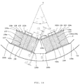
- FIG. 14 is an enlarged view of a part of FIG. 13 .
- the bearing device 100 illustrated in FIGS. 13 and 14 has a structure in which the annular electromagnet 101 is disposed in a non-contact manner and concentrically with the rotor shaft 102 on the radially outer side of the rotor shaft 102.
- the annular electromagnet 101 has a stator core 103 in an annular shape (referred to as "annular stator core 103" hereinafter) and a plurality of coil portions 104 attached to an inner peripheral wall 103a of the annular stator core 103.
- This bearing device 100 constitutes a magnetic bearing, and the rotor shaft 102 is configured to have only the degree of freedom of rotation around the axis.
- the annular stator core 103 is provided with eight teeth 103b that protrude from the inner peripheral wall 103a toward a center O, with predetermined intervals in a circumferential direction, at a phase angle of, in the illustrated embodiment, 2 ⁇ and 90° - 2 ⁇ .
- the cross-sectional shape of each tooth 103b is a rectangular shape.
- the coil portions 104 are attached to the teeth 103b respectively.
- Flat core bearing surfaces 103c for placing second flange portions 109 of bobbins 105 in close contact with the inner peripheral wall 103a are each provided in a base portion of each of the teeth 103b on which the respective coil portions 104 are mounted, that is, a part of the inner peripheral wall 103a of the annular stator core 103,
- the coil portions 104 include, respectively, the bobbins 105 and coils 106 formed by winding coil wires 106a around respective outer peripheries of the bobbins 105 a predetermined number of times.
- the bobbins 105 are each formed of an insulating material such as resin and each have a bobbin body 107, a first flange portion 108, and a second flange portion 109.
- the bobbin body 107 has a rectangular insertion hole 110 through which the corresponding tooth 103b can be inserted, and is a cylindrical body penetrating in in a front-rear direction and having a rectangular cross-sectional shape.
- the coil wire 106a of the coil 106 is wound around an outer peripheral surface of the bobbin body 107 the predetermined number of times.
- the first flange portion 108 is a rectangular flange portion having a rectangular hollow shape when viewed from the front, i.e., having a hole in the center thereof, and is provided on one end surface of the bobbin body 107 located near the center O of the annular stator core 103 so as to project from the outer peripheral surface of the bobbin body 107 to the outside at a substantially right angle.
- the second flange portion 109 is a rectangular flange portion having a rectangular hollow shape when viewed from the front, i.e., having a hole in the center thereof as with the first flange portion 108, and is provided on an end surface of the bobbin body 107, opposite to the first flange portion 108, so as to project from the outer peripheral surface of the bobbin body 107 to the outside at a substantially right angle.
- FIG. 13 shows the magnetic bearing device 100 in which the bobbins 105 having the coils 106 wound therearound are attached to the respective teeth 103b of the annular stator core 103 as described above.
- the magnetic bearing device 100 illustrated in FIG. 13 has a structure in which the annular electromagnet 101 is disposed in a non-contact manner and concentrically with the rotor shaft 102 on the radially outer side of the rotor shaft 102.
- the annular electromagnet 101 is a uniaxial electromagnet by using a pair of coil portions 104 illustrated in FIG. 13 .
- Four pairs of the uniaxial electromagnets are provided at a phase angle of 90 degrees, in which the rotor shaft 102 is attracted by the magnetic force generated by each of these electromagnets and supported in a non-contact manner.
- electromagnet 101 In the annular electromagnet 101 illustrated in FIG. 13 , four electromagnets are arranged in pairs along an X axis and a Y axis, as well as in a + direction and a - direction (if necessary, these electromagnets arranged in pairs these pairs are referred to as "electromagnet +X,” “electromagnet -X,” “electromagnet +Y,” and “electromagnet - Y").
- circumferential end surfaces 108a of the first flange portion 108 and circumferential end surfaces 108b of the second flange portion 109 are formed at right angles. Furthermore, the coil wire 106a of each of the coils 106 is wound from the first flange portion 108 to the second flange portion 109 of each bobbin 105 in such a manner that the cross-sectional shape of the bobbin 105 is a substantially rectangular shape. Specifically, rectangular winding is formed.
- An attractive force F of each uniaxial electromagnet can be obtained by the following equation (1).
- N is the number of turns of the coil wire 106a, i a current flowing through the coil wire 106a, R a magnetic resistance, S a magnetic pole area, u a magnetic permeability of an air gap, ⁇ a half angle, and k a constant.
- an interval L6 between the first flange portions 108 of the bobbins 105 adjacent to each other is equivalent to an interval between outer edges 108c, as illustrated in FIG. 14 .
- the interval L6 between these adjacent bobbins 105 is required as an interval for preventing the bobbins 105 from interfering with each other during assembly.
- a technical problem occurs for providing a vacuum pump, and a magnetic bearing device used for such a vacuum pump, and an annular electromagnet, the vacuum pump being capable of increasing the attractive force of electromagnets by increasing the number of turns of a coil wire wound around each bobbin, without changing the shape of the conventional annular stator core 103, i.e., the size of the conventional annular stator core such as, as illustrated in FIGS.
- magnetic pole half angle ⁇ thickness L1 of the coil 106, coil width L2, plate thickness L3 of the first flange portion 108, plate thickness L4 of the second flange portion 109, distance between the outermost periphery of the coil 106 and the outermost ends of the flange portions 108, 109 of each bobbin 105, which is the amount of projection L5 of the flange portions 108, 109 from the coil 106, interval L6 between the bobbins 105, interval L7 between the bobbins 105 and the core bearing surface end portions, and magnetic pole connecting thickness L8.
- An object of the present invention is to solve such a technical problem.
- an invention according claim 1 is a vacuum pump having a magnetic bearing device that is disposed radially outside of a rotor shaft and rotatably holds the rotor shaft, wherein the magnetic bearing device has an annular stator core having, on an inner peripheral wall thereof, a plurality of teeth provided at predetermined intervals in a circumferential direction of the rotor shaft, and an annular electromagnet having a plurality of bobbins attached to the teeth respectively, the plurality of bobbins having coil wires wound around outer peripheries thereof, the bobbins each having a rectangular cylindrical bobbin body that has the coil wire wound around the outer periphery thereof and is attached to each of the teeth, a first flange portion provided on an end surface of the bobbin body so as to face the rotor shaft and formed into a rectangular hallow shape as viewed from the front, a second flange portion provided on an end surface of the bobbin body so as to be opposite
- the coil winding amount increasing means for increasing the amount of winding of the coil wire wound around the bobbin body is provided at least on the first flange portion or the second flange portion, a vacuum pump can be realized in which the attractive force of the annular electromagnet is increased by increasing the number of turns of the coil wire wound around each bobbin, without changing the size of the annular stator core of the prior art, so that the vacuum pump can be operated while keeping the rotating rotor shaft stable.
- An invention according to claim 2 provides, in the configuration described in claim 1, a vacuum pump in which the coil winding amount increasing means has, on circumferential end faces of the first flange portion, chamfers that are inclined inward from outer edges of the first flange portion in the plate thickness direction.
- the distance between the inner edges of the first flange portions of the adjacent bobbins can be increased by providing the circumferential end surfaces of each of the first flange portions with chamfers that are inclined inward from the outer edges of each first flange portion in the plate thickness direction. Therefore, even when the adjacent bobbins that are arranged on the inner peripheral wall of the annular stator core face the center, the inner edges do not interfere with each other, keeping the distance between the outer edges of the first flange portions wide. Thus, even when the amount of projection of each first flange portion is increased so that the outer edges of the first flange portions of the adjacent bobbins come close to each other, the first flange portions of the adjacent bobbins do not interfere with each other during assembly.
- the vacuum pump can be realized by increasing the distance between the circumferential end surfaces of the first flange portions of the bobbins (the amount of projection of the first flange portion) and increasing and the number of turns of the coil wires to enhance the attractive force of the annular electromagnet, which enables an operation of the vacuum pump while keeping the rotating rotor shaft stable.
- An invention according to claim 3 provides, in the configuration described in claim 1 or 2, a vacuum pump in which the coil winding amount increasing means has, on the circumferential end faces of at least the first flange portion of each of the plurality of bobbins adjacent to each other, notches that accommodate parts of the plurality of adjacent bobbins adjacent to each other.
- the first flange portions of the adjacent bobbins do not interfere with each other during assembly even when the amount of projection of the first flange portions of the adjacent bobbins is increased to shorten the distance between the inner edges of the first flange portions. Therefore, by increasing the amount of projection of the flange portions to bring the inner edges of the first flange portions of the adjacent bobbins closer to each other, the coil wire is wound as much as possible around each of the adjacent bobbins, to further enhance the attractive force of the annular electromagnet. Consequently, the vacuum pump can be operated while keeping the rotating rotor shaft more stable. Note that better results can be expected by providing these notches in both the first and second flange portions.
- An invention according to claim 4 provides, in the configuration described in claim 1, 2, or 3, a vacuum pump in which the coil winding amount increasing means has, on circumferential end faces of the second flange portion, chamfers that are inclined inward from inner edges of the second flange portion in the plate thickness direction.
- the present invention can realize a vacuum pump in which the attractive force of the annular electromagnet is increased by increasing the amount of circumferential projection of the second flange portion of each bobbin and increasing the number of turns of the coil wire, so that the vacuum pump can be operated while keeping the rotating rotor shaft stable.
- An invention described in claim 5 provides a magnetic bearing device that is used in the vacuum pump described in any one of claims 1 to 4.
- the present invention can realize a magnetic bearing device in which the attractive force of the annular electromagnet is increased by increasing the number of turns of the coil wire wound around the bobbin body, so that the magnetic bearing device can be operated while keeping the rotating rotor shaft stable.
- An invention described in claim 6 provides an annular electromagnet that is used in the vacuum pump described in any one of claims 1 to 4.
- the present invention can realize an annular electromagnet in which the attractive force thereof is increased by increasing the number of turns of the coil wire wound around the bobbin body, so that the annular electromagnet can be operated while keeping the rotating rotor shaft stable.
- the present invention can achieve a vacuum pump capable of increasing the attractive force of electromagnets by increasing the number of turns of a coil wire wound around each bobbin without changing the shape of the annular stator core of the prior art, and a magnetic bearing device and an annular electromagnet that are used in the vacuum pump.
- the present invention achieved the object with a vacuum pump having a magnetic bearing device that is disposed radially outside of a rotor shaft and rotatably holds the rotor shaft, wherein the magnetic bearing device has an annular stator core having, on an inner peripheral wall thereof, a plurality of teeth provided at predetermined intervals in a circumferential direction of the rotor shaft, and an annular electromagnet having a plurality of bobbins attached to the teeth respectively, the plurality of bobbins having coil wires wound around outer peripheries thereof, the bobbins each having a rectangular cylindrical bobbin body that has the coil wire wound around the outer periphery thereof and is attached to each of the teeth, a first flange portion provided on an end surface of the bobbin body so as to face the rotor shaft and formed into a rectangular hall
- FIG. 1 is a diagram showing a schematic configuration of a vacuum pump 10 according to the present embodiment. Note that FIG. 1 shows a cross section of the vacuum pump 10 along an axial direction thereof. In this embodiment, a so-called composite blade type vacuum pump having a vacuum pump portion T and a thread groove pump portion S is described as an embodiment of the vacuum pump 10. Note that the present embodiment may be applied to a pump having only the vacuum pump portion T or a pump in which a thread groove is provided on the rotating body side.
- a casing 11 configuring a housing of the vacuum pump 10 has a cylindrical shape and constitutes the housing of the vacuum pump 10 together with a base 12 provided in a bottom portion of the casing 11.
- a gas transfer mechanism which is a structure bringing about exhaust functions of the vacuum pump 10, is stored inside the housing of the vacuum pump 10.
- the gas transfer mechanism in the vacuum pump 10 includes the vacuum pump portion T provided on the inlet port 13 side and the thread groove pump portion S provided on the outlet port 14 side.
- the structure bringing about these exhaust functions is composed mainly of a rotating portion supported rotatably and a stator portion fixed to the casing 11. Furthermore, a controller 28 for controlling the operation of the vacuum pump 10 is connected to the outside of the housing of the vacuum pump 10.
- the rotating portion is composed of a rotor shaft (shaft) 16 rotated by a motor portion 15 described hereinafter, and a rotor portion 17.
- the rotor shaft 16 is a rotating shaft of a cylindrical member.
- the rotor portion 17 is attached to an upper end of the rotor shaft 16 by a plurality of bolts 18.
- the rotor portion 17 is a rotating member disposed on the rotor shaft 16.
- the rotor portion 17 includes rotor blades 19 provided on the inlet port 13 side (the vacuum pump portion T), a cylindrical member 20 provided on the outlet port 14 side (the thread groove pump portion S), and the like.
- the rotor portion 17 is made of a metal such as stainless steel or an aluminum alloy.
- the rotor blades 19 are configured by a plurality of blades extending radially from the rotor portion 17 at a predetermined angle from a plane perpendicular to an axis of the rotor shaft 16. In the vacuum pump 10, the rotor blades 19 are provided in a plurality of stages in the axial direction.
- the cylindrical member 20 is composed of a member, an outer peripheral surface of which has a cylindrical shape.
- the motor portion 15 for rotating the rotor shaft 16 is provided in the middle of the rotor shaft 16 in the axial direction thereof.
- the present embodiment assumes that the motor portion 15 is configured by, for example, a DC brushless motor.
- a permanent magnet 15a is fixed to a part of the rotor shaft 16 that configures the motor portion 15.
- the permanent magnet 15a is fixed in such a manner that, for example, the N pole and the S pole thereof are arranged 180 degrees apart around the rotor shaft 16.
- electromagnets 15b are arranged 60 degrees apart around the permanent magnet 15a, with a predetermined gap (air gap) from the rotor shaft 16 in such a manner as to be symmetrical with respect to the axis of the rotor shaft 16 and to be opposed to one another.
- the permanent magnet 15a functions as a rotor portion (rotating portion) of the motor portion 15, and the electromagnets 15b function as a stator portion (stationary portion) of the motor portion 15.
- the vacuum pump 10 has a sensor for detecting a rotation speed and a rotation angle (phase) of the rotor shaft 16, and by means of this sensor, the controller 28 can detect the positions of the magnetic poles of the permanent magnet 15a fixed to the rotor shaft 16.
- the controller 28 switches currents of the electromagnets 15b of the motor portion 15 successively, to generate a rotating magnetic field around the permanent magnet 15a of the rotor shaft 16.
- the permanent magnet 15a fixed to the rotor shaft 16 follows this rotating magnetic field, thereby rotating the rotor shaft 16.
- a radial magnetic bearing portion 21 and a radial magnetic bearing portion 22 that support the rotor shaft 16 in a radial direction, that is, support a load of the rotating portion in the radial direction.
- a lower end of the rotor shaft 16 is provided with a thrust magnetic bearing portion 23 that supports the rotor shaft 16 in the axial direction (thrust direction), that is, supports the load of the rotating portion in the thrust direction.
- the rotor shaft 16 (rotating portion) is supported by the radial magnetic bearing portions 21 and 22 in a non-contact manner in the radial direction (radial direction of the rotor shaft 16), and is supported by the thrust magnetic bearing portion 23 in a non-contact manner in the thrust direction (axial direction of the rotor shaft 16).
- These magnetic bearings constitute a so-called five-axis control type magnetic bearing, and the rotor shaft 16 only has a degree of freedom of rotation around the axis.
- the radial magnetic bearing portion 21 for example, four electromagnets 21b are arranged 90 degrees apart around the rotor shaft 16 in such a manner as to face each other. These electromagnets 21b are arranged, with a gap (air gap) from the rotor shaft 16. Note that this gap value takes into consideration the amount of vibration (swing amount) of the rotor shaft 16 in a steady state, the spatial distance between the rotor portion 17 and the stator portion (stationary portion), the performance of the radial magnetic bearing portion 21, and the like. Also, a target 21a is formed on the rotor shaft 16 facing the electromagnets 21b.
- the target 21a is attracted by the magnetic force of the electromagnets 21b of the radial magnetic bearing portion 21, whereby the rotor shaft 16 is supported in a non-contact manner in the radial direction.
- the target 21a functions as a rotor portion of the radial magnetic bearing portion 21, and the electromagnets 21b function as stator portions of the radial magnetic bearing portion 21.
- the radial magnetic bearing portion 22, too, has the same configuration as the radial magnetic bearing portion 21. Specifically, a target 22a is attracted by the magnetic force of electromagnets 22b of the radial magnetic bearing portion 22, whereby the rotor shaft 16 is supported in a non-contact manner in the radial direction.
- the thrust magnetic bearing portion 23 causes the rotor shaft 16 to levitate in the axial direction via a disc-shaped metal armature 24 that is provided perpendicular to the rotor shaft 16.
- a disc-shaped metal armature 24 that is provided perpendicular to the rotor shaft 16.
- two electromagnets 23a, 23b are arranged so as to face each other via the armature 24. These electromagnets 23a, 23b are arranged, with a gap from the armature 24. Note that this gap value takes into consideration the amount of vibration of the rotor shaft 16 in a steady state, the spatial distance between the rotor portion 17 and the stator portion, the performance of the thrust magnetic bearing portion 23, and the like.
- the armature 24 is attracted by the magnetic force of the electromagnets of the thrust magnetic bearing portion 23, whereby the rotor shaft 16 is supported in a non-contact manner in the thrust direction (axial direction).
- displacement sensors 25, 26 are formed in the vicinity of the radial magnetic bearing portions 21, 22, respectively, so that displacement of the rotor shaft 16 in the radial direction can be detected.
- a displacement sensor 27 is formed at the lower end of the rotor shaft 16, so that displacement of the rotor shaft 16 in the axial direction can be detected.
- the displacement sensors 25, 26 are elements for detecting displacement of the rotor shaft 16 in the radial direction and, in the present embodiment, are configured by inductance-type sensors such as eddy current sensors having coils 25b, 26b.
- the coils 25b, 26b of the displacement sensors 25, 26 are part of an oscillation circuit, not illustrated, which is formed in the controller installed outside the vacuum pump 10.
- the displacement sensor 25 is configured to have a high-frequency current flow therein as the oscillation circuit oscillates, thereby generating a high-frequency magnetic field on the rotor shaft 16. Then, the oscillation amplitude of the oscillation circuit changes when the distance between the displacement sensors 25, 26 and the targets 25a, 26a changes, whereby the displacement of the rotor shaft 16 can be detected.
- the sensors for detecting displacement of the rotor shaft 16 are not limited to the foregoing sensors, and, for example, capacitive sensors or optical sensors may be used.
- the controller 28 adjusts the magnetic force of each of the electromagnets 21b, 22b of the radial magnetic bearing portions 21, 22 to bring the rotor shaft 16 back to a predetermined position. In this manner, the controller 28 performs feedback control on the radial magnetic bearing portions 21, 22 on the basis of the signals from the displacement sensors 25, 26. As a result, the rotor shaft 16 is magnetically levitated in the radial direction, via a predetermined air gap from the electromagnets 21b, 22b in the radial magnetic bearing portions 21, 22, and held in the air in a non-contact manner.
- the displacement sensor 27 is configured to have a coil 27b.
- the displacement sensor 27 detects displacement of the rotor shaft 16 in the thrust direction by detecting the distance between the coil 27b and a coil 27a that is provided on the rotor shaft 16 side so as to face the coil 27b.
- the controller 28 adjusts the magnetic force of each of the electromagnets 23a 23b of the thrust magnetic bearing portion 23 to bring the rotor shaft 16 back to a predetermined position. In this manner, the controller 28 performs feedback control on the thrust magnetic bearing portion 23 on the basis of the signal from the displacement sensor 27.
- the rotor shaft 16 is magnetically levitated in the thrust direction, via a predetermined air gap from each of the electromagnets 23a, 23b in the thrust magnetic bearing portion 23, and held in the air in a non-contact manner.
- the rotor shaft 16 Since the rotor shaft 16 is held by the radial magnetic bearing portions 21, 22 in the radial direction and held by the thrust magnetic bearing portion 23 in the thrust direction as described above, the rotor shaft 16 can rotate about the axis.
- the motor portion 15 and each of the magnetic bearing portions 21, 22 of the present embodiment function as the annular electromagnets 21b according to the present invention that use the actions of electromagnet force.
- FIGS. 2 and 3 Configurations of the magnetic bearing portions 21, 22 are further described using FIGS. 2 and 3 . Since the magnetic bearing portions 21, 22 share the same configuration, the structure of the magnetic bearing portion 21 is mainly described. Therefore, although FIGS. 2 and 3 each show the cross section of the part corresponding to line D-D of FIG. 1 , the illustration of the hatched sections is omitted in order to simplify the drawings.
- the magnetic bearing portion 21, which is a magnetic bearing device, has a structure in which the electromagnets 21b, which are annular electromagnets (referred to as “annular electromagnets 21b” hereinafter), are arranged in a non-contact manner and concentrically with the rotor shaft 16 on the radially outer side of the rotor shaft 16.
- the annular electromagnets 21b each have a stator core 31 in an annular shape (referred to as “annular stator core 31" hereinafter) and a plurality of coil portions 32 attached to an inner peripheral wall 31a of the annular stator core 31.
- the annular stator core 31 is formed from a laminated silicon steel sheet and is provided with eight teeth 31b that protrude so as to project from an inner peripheral wall 31a toward a center O of the annular stator core 31 (which is also the center O of the rotor shaft 16), with predetermined intervals in the circumferential direction, at a phase angle of, in the illustrated embodiment, 2 ⁇ and 90°-2 ⁇ .
- the cross-sectional shape of each of the teeth 31b is a rectangular shape.
- the coil portions 32 are attached to the teeth 31b respectively.
- Flat core bearing surfaces 31c for placing second flange portions 37 of bobbins 33 in close contact with the inner peripheral wall 31a are provided at base portions of the respective teeth 31b on which the respective coil portions 32 are mounted, the base portions being part of the inner peripheral wall 31a of the annular stator core 31.
- the coil portions 32 include, respectively, the bobbins 33 and coils 34 formed by winding coil wires 34a around the outer peripheries of the bobbins 33 a predetermined number of times.
- the bobbins 33 are each formed of an insulating material such as resin and each integrally have a bobbin body 35, a first flange portion 36, and a second flange portion 37.
- the bobbin body 35 is a cylindrical body having a rectangular cross section, which penetrates in a front-rear direction and has a rectangular insertion hole 38 through which the corresponding tooth 31b can be inserted.
- the bobbin body 35 is a rectangular cylindrical body (so-called square tube).
- the coil wire 34a of the coil 34 is wound around an outer peripheral surface of the bobbin body 35 the predetermined number of times.
- the first flange portion 36 is a flat flange portion having a rectangular hollow shape when viewed from the front, i.e., having a hole in the center thereof, and is provided on one end surface of the bobbin body 35 located near the center O of the annular stator core 31 in such a manner as to protrude from the outer peripheral surface of the bobbin body 35 to the outside at a substantially right angle.
- the second flange portion 37 is a flat flange portion having a rectangular hollow shape when viewed from the front, i.e., having a hole in the center thereof as with the first flange portion 36, and is provided on an end surface of the bobbin body 35, opposite to the first flange portion 36, in such a manner as to protrude from the outer peripheral surface of the bobbin body 35 to the outside at a substantially right angle.
- each of the bobbins 33 formed as described above after winding the coil wire 34a around the outer peripheral surface of the bobbin body 35 the predetermined number of times, the tooth 31b of the corresponding annular stator core 31 is inserted from the other end side of the bobbin body 35 that is provided with the second flange portion 37, to mount the bobbin 33 onto the tooth 31b. Then, the second flange portion 37 of the bobbin 33 is placed in close contact with the core bearing surface 31c and fixed to the tooth 31b by a means which is not illustrated (e.g., by means of fitting, bonding, etc.).
- each annular electromagnet 21b is a uniaxial electromagnet using a pair of coil portions 32 illustrated in FIG. 3 .
- Four pairs of the uniaxial electromagnets are provided at a phase angle of 90 degrees, in which the rotor shaft 16 is attracted by the magnetic force generated by each of these electromagnets and supported in a non-contact manner.
- FIGS. 2 and 3 In the annular electromagnet 21b illustrated in FIGS. 2 and 3 , four electromagnets are arranged in pairs along the X axis and the Y axis, as well as in the + direction and the - direction (if necessary, these electromagnets arranged in pairs are referred to as "electromagnet +X,” “electromagnet -X,” “electromagnet +Y,” and “electromagnet -Y”). Since these electromagnets +X, -X, +Y, and -Y share the same structure, FIG. 3 only shows the electromagnet -Y. Thus, the configuration of the electromagnet -Y described below is applied to the electromagnets +X, -X, and +Y as well.
- the electromagnet -Y of the embodiment illustrated in FIG. 3 is a uniaxial electromagnet configured by an electromagnet -Y1 and an electromagnet -Y2.
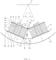
- the bobbin 33 attached to the tooth 31b of the electromagnet -Y1 and the bobbin 33 attached to the tooth 31b of the electromagnet -Y2 circumferential end surfaces 36a of the first flange portion 36 and circumferential end surfaces 37a of the second flange portion 37 are chamfered into coil winding amount increasing means 30.
- the electromagnet -Y1 and the electromagnet -Y2 are symmetrical with respect to ⁇ angle and that the parts of the electromagnet -Y1 and the parts of the electromagnet -Y2 share the same structure. Therefore, in FIG. 3 , the detailed reference numerals corresponding to the description are given only to the electromagnet -Y1, but for the electromagnet -Y2, reference numerals are given generically and omitted accordingly.
- each end surface 36a of the first flange portion 36 is chamfered to have a width L9 so as to be inclined inward at a chamfer angle ⁇ from an outer edge 36b to an inner edge 36c in the direction of a plate thickness L3 of the first flange portion 36.
- ⁇ 90° - 2 ⁇ , L9 ⁇ L3.
- This chamfering of each end surface 36a of the first flange portion 36 reduces a protrusion amount L61 of the inner edge 36c to effectively increase the interval L6 between the first flange portions 36.
- the protrusion amount L61 contributes to increasing the interval between the bobbins 33, that is, the amount of projection of the first flange portion 36, and allows the first flange portion 36 to project to both sides in the circumferential direction, to contribute to increasing the number of turns of the coil wire 34a.
- This interval increase L6 between the bobbins 33 is obtained by the following equation (2).
- L 61 L 9 ⁇ sin 2 ⁇ ⁇
- Each end surface 37a of the second flange portion 37 is chamfered to have a width L10 so as to be inclined inward at a chamfer angle ⁇ from an inner edge 37c to an inner edge 37b in the direction of a plate thickness L4 of the second flange portion 37.
- L10 ⁇ L4.
- This chamfering of each end surface 37a of the second flange portion 37 reduces a protrusion amount L71 of the inner edge 37c to effectively increase an interval L7 between an end portion of the corresponding core bearing surface 31c and the bobbin 33 (L7 + L71).
- the protrusion amount L71 contributes to increasing the amount of projection of the second flange portion 37, and allows the second flange portion 37 to project to both sides in the circumferential direction, to contribute to increasing the number of turns of the coil wire 34a.
- the interval L71 between the end portion of the core bearing surface 31c and the bobbin 33 is obtained by the following equation (3).
- L 71 L 10 / tan ⁇ ⁇
- a magnetic pole connecting thickness L81 between the bobbins 33 can also be increased.
- L8 represents a magnetic pole connecting thickness obtained by not chamfering each end surface 37a of the second flange portion 37 according to the illustrated embodiment
- the magnetic pole connecting thickness L81 of the illustrated embodiment is expressed by the following equation (4), in which it is clear that the magnetic pole connecting thickness L81 according to the illustrated embodiment is greater than the magnetic pole connecting thickness L8 of the structure of the prior art.
- L 81 L 8 + L 7 ⁇ sin ⁇ ⁇ > L 8
- a thickness L11 of each coil 34 is expressed by the following equation (5), and the number of turns of the coil wire 34a can be made greater than the thickness L1 of the coil 34 when the interval L61 between the bobbins 33 illustrated in FIG. 3 is not narrowed.
- L 11 L 1 + L 9 ⁇ tan 2 ⁇ ⁇ > L 1
- circumferential end surfaces 37a of the second flange portion 37 are each chamfered at an angle from the inner edge 37c toward the inside in the direction of the plate thickness L4 of the second flange portion 37, these inclined chamfered surfaces function as the coil winding amount increasing means 30 and dodge the curved shape (magnetic pole connecting part) of the inner peripheral wall 31a of the annular stator core 31, resulting in an increase of the amount of projection between the circumferential end surfaces of the second flange portions 37 of the bobbins 33. Therefore, the number of turns of each coil wire 34a can be increased and thereby the attractive force of the annular electromagnet 21b can be enhanced. Moreover, a magnetic pole connecting thickness L82 according to the present embodiment and the conventional magnetic pole thickness L8 of the prior art establish the chamfer angle ⁇ so as to satisfy L82 ⁇ L8.
- L71 ⁇ L7 + L9 ⁇ tan2 ⁇ /2 tan ⁇ ⁇ L10/(L7 + L9 ⁇ tan 2 ⁇ /2) are established, in which the number of turns of each coil wire 34a and the attractive force of the annular electromagnet 21b can be increased by increasing ⁇ .
- the bobbins 33 of the annular electromagnet 21b of the foregoing embodiment adopt the structure in which the circumferential end surfaces 36a of each of the first flange portions 36 and the circumferential end surfaces 37a of each of the second flange portions 37 of the electromagnets -Y1 and -Y2 are chamfered.
- chamfering does not need to be performed on the end surfaces of the both electromagnets but may be performed as in the following (a) to (c) or by combining them, as illustrated in FIGS. 2 and 3 .
- FIGS. 5 to 7 each show a first modification of the annular stator core 31.
- FIGS. 5 and 6 correspond to the electromagnet -Y illustrated in FIGS. 3 and 4 and omit the illustration of the hatched section for the purpose of simplification.
- FIGS. 7A and 7B show the bobbins 33 of the annular stator core 31 of FIGS. 5 and 6 .
- FIGS. 7A and 7B are a plan view taken along arrows A and B of FIG. 5 .
- the same reference numerals are given to the parts corresponding to the annular stator core 31 illustrated in FIG. 2 to 4 , and redundant explanations are omitted accordingly. Thus, only the parts having different configurations are described.
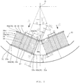
- the electromagnet -Y1 and the electromagnet -Y2 illustrated in the first modification are symmetrical with respect to the ⁇ angle, and the parts of the electromagnet -Y1 and the parts of the electromagnet -Y2 share the same structure. Therefore, in FIGS. 5 and 6 , the detailed reference numerals corresponding to the description are given only to the electromagnet -Y1, but for the electromagnet -Y2, reference numerals are given generically and omitted accordingly.
- the electromagnet -Y illustrated in FIGS. 5 and 6 is a uniaxial electromagnet having the electromagnet -Y1 and the electromagnet -Y2.
- a plurality of recess portions 40a that function as notches for accommodating portions 39a of these adjacent bobbins 33 are arranged as the coil winding amount increasing means, at a predetermined pitch along a vertical direction, on the circumferential end surfaces 36a of the respective first flange portions 36.
- the recess portion 40a on the right side and the left side of the first flange portion 36 of the bobbin 33 attached to the tooth 31b of the electromagnet -Y1 are shifted by approximately 1 pitch in the vertical direction in relation to the recess portions 40a on the left side and right side of the first flange portion 36 of the bobbin 33 attached to the tooth 31b of the electromagnet -Y2.
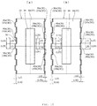
- the circumferential end surfaces 37a of the second flange portions 37 of the bobbin 33 attached to the tooth 31b of the electromagnet -Y1 and of the bobbin 33 attached to the tooth 31b of the electromagnet -Y2, too, are provided with a plurality of recess portions 40b as notches which are arranged at approximately the same pitch as in the both circumferential end surfaces 36a of the first flange portions 36 and accommodate the portions 39b of the bobbins 33, as indicated by the parenthesized reference numerals illustrated in FIGS. 7A and 7B .
- each recess portion 40a in the first flange portions 36 and the width L24 of each recess portion 40b in the second flange portion 37 are configured to be greater than the distance L21 between the recess portions 40a of each first flange portion 36 and the distance L25 between the recess portions 40b of each second flange portion 37 (L20 > L21, L24 ⁇ L25).
- the portions 39b and 39a of the second flange portion 37 in the bobbin 33 of the electromagnet -Y2 are sequentially fitted in the recess portions 40a on the right hand side of the bobbin 33 of the electromagnet -Y1 and are dodged when the bobbin 33 of the electromagnet -Y1 and the bobbin 33 of the electromagnet -Y2 are attached to the respective teeth 31b.
- the bobbins 33 adjacent to each other can be attached to the respective teeth 31b so as not to interfere with each other.
- increasing the amount of projection of the first flange portion 36 and the amount of projection of the second flange portion 37 in the bobbins 33 allows the coil wires 34a to be wound up to approximately 1/2 the notch depth L15 of the recess portions 40a. Therefore, the number of turns of the coil wires 34a can be increased and thereby the thickness L1 of the coils 34 can be increased.
- a thickness L12 of each coil 34 illustrated in FIG. 6 is L1 + L15/2 > L1, with L15 being the notch depth of each first flange portion 36, the coils 34 having a higher number of turns of the coil wires 34a can be obtained.
- FIGS. 8 to 12 each show a second modification of the annular stator core 31.
- FIGS. 8 and 9 correspond to the electromagnet -Y illustrated in FIGS. 3 and 4 and omit the illustration of the hatched section for the purpose of simplification.
- FIGS. 10 to 12 each show the bobbins 33 of the annular stator core 31 of FIGS. 8 and 9 .
- FIGS. 10A and 10B are a plan view taken along arrows A and B of FIG. 8 .
- FIG. 11 is a schematic perspective view showing the bobbins 33 from the center of the annular stator core 31.
- FIG. 12 is a schematic perspective view showing the bobbins 33 from the outer periphery side of the annular stator core 31.
- the second modification illustrated in FIGS. 8 to 12 is a modification that is further developed by combining the embodiment illustrated in FIGS. 2 to 4 and the first modification illustrated in FIGS. 5 to 7 . Therefore, the same reference numerals are given to the parts corresponding to the annular stator core 31 illustrated in FIGS. 2 to 7 , and redundant explanations are omitted accordingly. Thus, only the parts having different configurations are described.
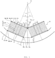
- the electromagnet -Y1 and the electromagnet -Y2 illustrated in the second modification are symmetrical with respect to the ⁇ angle, and the parts of the electromagnet -Y1 and the parts of the electromagnet -Y2 share the same structure. Therefore, in FIGS. 8 and 9 , the detailed reference numerals corresponding to the description are given only to the electromagnet -Y1, but for the electromagnet -Y2, reference numerals are given generically and omitted accordingly.
- the electromagnet -Y illustrated in FIGS. 8 and 9 is a uniaxial electromagnet having the electromagnet -Y1 and the electromagnet -Y2.
- circumferential end surfaces 36a, 36a1 of the first flange portion 36 and circumferential end surfaces 37a, 37a1 of the second flange portion 37 are chamfered to have widths L9, L91, L10, L17 that are inclined at chamfer angles ⁇ , ⁇ 1, ⁇ , ⁇ 1 and are provided with a plurality of recess portions 40a, 40b that function as notches for accommodating the portions 39a, 39b of these adjacent bobbins 33.
- the chamfers and the recess portions 40a, 40b function as the coil winding amount increasing means 30.
- FIG. 11 and 12 each show the bobbins 33 that are provided with the chamfers and recess portions 40a, 40b formed on the circumferential end surfaces 36a, 36a1, 37a of the first flange portions 36 and the second flange portions 37.
- FIG. 11 is a schematic perspective view showing the bobbins from the center of the annular stator core 31
- FIG. 12 is a schematic perspective view showing the bobbins from the outer periphery of the annular stator core 31.
- the interval L6 between the first flange portions 36 can be narrowed in such a manner that the amount of projection of the first flange portions 36 is increased so that the first flange portions 36 come close to each other, as illustrated in FIG. 9 , from the state in which the first flange portions 36 of the adjacent bobbins 33 are separated from each other as illustrated in FIG. 8 .
- the thickness of the coil wires 34a can be increased from L1 to L13, thereby making the number of turns of the coil wires 34a greater than the thickness L1 of the coil 34.
- L 13 L 1 + L 15 / 2 + L 9 ⁇ tan 2 ⁇ ⁇ / 2 > L 1
- the circumferential end surfaces 37a of the second flange portion 37 are chamfered so as to be inclined inward from the inner edge 37c in the direction of the plate thickness L4 of the second flange portion 37, this chamfering functions as the coil winding amount increasing means 30, and these inclined chamfered surfaces dodge the curved shape (magnetic pole connecting part) of the inner peripheral wall 31a of the annular stator core 31, increasing the amount of circumferential projection of the second flange portions 37 of the bobbins 33 and the number of turns of the coil wires 34a.
- the chamfer angle ⁇ is set so that the magnetic pole connecting thickness L83 becomes greater than the magnetic pole connecting thickness L8 of the prior art (L83 ⁇ L8).
- the recess portions 40b that function as the notches for accommodating the portions 39b of the bobbins 33 are provided in the bobbin 33 attached to the tooth 31b of the electromagnet -Y1 and the bobbin 33 attached to the tooth 31b of the electromagnet -Y2, the first flange portions 36 of these adjacent bobbins 33 do not interfere with each other at the time of assembly. Accordingly, the distance between the circumferential end surfaces (the amount of projection) of the first flange portions 36 of the bobbins 33 can be increased, and, with the resultant coil winding amount increasing means 30, the number of turns of the coil wires 34a can be increased and thereby the attractive force of the annular electromagnet 21b can be enhanced.
- the present invention can also be applied to a bobbin of a coil having a rectangular winding or a trapezoidal winding with an offset illustrated in FIGS. 15 and 16 .
- Various modifications can be made to the present invention without departing from the spirit of the present invention, and it goes without saying that the present invention extends to such modifications.
Landscapes
- Engineering & Computer Science (AREA)
- General Engineering & Computer Science (AREA)
- Power Engineering (AREA)
- Mechanical Engineering (AREA)
- Physics & Mathematics (AREA)
- Electromagnetism (AREA)
- Magnetic Bearings And Hydrostatic Bearings (AREA)
- Non-Positive Displacement Air Blowers (AREA)
- Connection Of Motors, Electrical Generators, Mechanical Devices, And The Like (AREA)
Abstract
Description
- The present invention relates to a vacuum pump, and a magnetic bearing device and an annular electromagnet used in the vacuum pump. Particularly, the present invention relates to a vacuum pump that is small and capable of improving the attractive force of an electromagnet, and a magnetic bearing device and an annular electromagnet used in the vacuum pump.
- In a rotating machine or the like under a special environment such as a vacuum pump, a magnetic bearing device for supporting a rotating body in a non-contact manner is often used as a bearing device (see Japanese Patent Application Laid-open No.
2006-83923 - The magnetic bearing device is typically configured to support the load of the rotating body in a non-contact manner by attracting a target provided on the rotating body by means of a plurality of electromagnets provided around the rotating body. Therefore, in a case where the electromagnets do not attract the target of the rotating body with appropriate attracting force (magnetic force), bearing accuracy may be lowered.
- Japanese Patent Application Laid-open No.
2006-83923 - A schematic structure of the magnetic bearing device of the prior art is explained using
FIGS. 13 and14 .FIG. 13 is a diagram showing a horizontal cross section of a magnetic bearingdevice 100, viewed from above, in which arotor shaft 102 is levitated and supported in the air by anannular electromagnet 101.FIG. 14 is an enlarged view of a part ofFIG. 13 . - The
bearing device 100 illustrated inFIGS. 13 and14 has a structure in which theannular electromagnet 101 is disposed in a non-contact manner and concentrically with therotor shaft 102 on the radially outer side of therotor shaft 102. Theannular electromagnet 101 has astator core 103 in an annular shape (referred to as "annular stator core 103" hereinafter) and a plurality ofcoil portions 104 attached to an innerperipheral wall 103a of theannular stator core 103. This bearingdevice 100 constitutes a magnetic bearing, and therotor shaft 102 is configured to have only the degree of freedom of rotation around the axis. - The
annular stator core 103 is provided with eightteeth 103b that protrude from the innerperipheral wall 103a toward a center O, with predetermined intervals in a circumferential direction, at a phase angle of, in the illustrated embodiment, 2α and 90° - 2α. The cross-sectional shape of eachtooth 103b is a rectangular shape. Thecoil portions 104 are attached to theteeth 103b respectively. Flat core bearingsurfaces 103c for placingsecond flange portions 109 ofbobbins 105 in close contact with the innerperipheral wall 103a are each provided in a base portion of each of theteeth 103b on which therespective coil portions 104 are mounted, that is, a part of the innerperipheral wall 103a of theannular stator core 103, - The
coil portions 104 include, respectively, thebobbins 105 andcoils 106 formed by windingcoil wires 106a around respective outer peripheries of the bobbins 105 a predetermined number of times. - The
bobbins 105 are each formed of an insulating material such as resin and each have abobbin body 107, afirst flange portion 108, and asecond flange portion 109. - The
bobbin body 107 has arectangular insertion hole 110 through which thecorresponding tooth 103b can be inserted, and is a cylindrical body penetrating in in a front-rear direction and having a rectangular cross-sectional shape. Thecoil wire 106a of thecoil 106 is wound around an outer peripheral surface of thebobbin body 107 the predetermined number of times. - The
first flange portion 108 is a rectangular flange portion having a rectangular hollow shape when viewed from the front, i.e., having a hole in the center thereof, and is provided on one end surface of thebobbin body 107 located near the center O of theannular stator core 103 so as to project from the outer peripheral surface of thebobbin body 107 to the outside at a substantially right angle. - The
second flange portion 109 is a rectangular flange portion having a rectangular hollow shape when viewed from the front, i.e., having a hole in the center thereof as with thefirst flange portion 108, and is provided on an end surface of thebobbin body 107, opposite to thefirst flange portion 108, so as to project from the outer peripheral surface of thebobbin body 107 to the outside at a substantially right angle. - In each of the
bobbins 105 formed as described above, after winding thecoil wire 106a around the outer peripheral surface of thebobbin body 107 the predetermined number of times, thecorresponding tooth 103b of theannular stator core 103 is inserted from the other end side of thebobbin body 107 provided with thesecond flange portion 109, to mount thebobbin 105 onto thetooth 103b. Then, thesecond flange portion 109 of thebobbin 105 is placed in close contact with thecore bearing surface 103c and fixed to thetooth 103b by a means which is not illustrated (e.g., by means of fitting, bonding, etc.).FIG. 13 shows the magnetic bearingdevice 100 in which thebobbins 105 having thecoils 106 wound therearound are attached to therespective teeth 103b of theannular stator core 103 as described above. - The magnetic bearing
device 100 illustrated inFIG. 13 has a structure in which theannular electromagnet 101 is disposed in a non-contact manner and concentrically with therotor shaft 102 on the radially outer side of therotor shaft 102. Theannular electromagnet 101 is a uniaxial electromagnet by using a pair ofcoil portions 104 illustrated inFIG. 13 . Four pairs of the uniaxial electromagnets are provided at a phase angle of 90 degrees, in which therotor shaft 102 is attracted by the magnetic force generated by each of these electromagnets and supported in a non-contact manner. - In the
annular electromagnet 101 illustrated inFIG. 13 , four electromagnets are arranged in pairs along an X axis and a Y axis, as well as in a + direction and a - direction (if necessary, these electromagnets arranged in pairs these pairs are referred to as "electromagnet +X," "electromagnet -X," "electromagnet +Y," and "electromagnet - Y"). - According to the structure of the
annular electromagnet 101, as illustrated inFIG. 14 , in thebobbin 105 attached to each of therespective teeth 103b of a pair of electromagnets -Y1, -Y2,circumferential end surfaces 108a of thefirst flange portion 108 andcircumferential end surfaces 108b of thesecond flange portion 109 are formed at right angles. Furthermore, thecoil wire 106a of each of thecoils 106 is wound from thefirst flange portion 108 to thesecond flange portion 109 of eachbobbin 105 in such a manner that the cross-sectional shape of thebobbin 105 is a substantially rectangular shape. Specifically, rectangular winding is formed. - An attractive force F of each uniaxial electromagnet can be obtained by the following equation (1).

coil wire 106a, i a current flowing through thecoil wire 106a, R a magnetic resistance, S a magnetic pole area, u a magnetic permeability of an air gap, α a half angle, and k a constant. - From the equation (1), it is clear that the attractive force F of each uniaxial electromagnet (electromagnet +X, electromagnet -X, electromagnet +Y, electromagnet -Y) is proportional to the square of the number of turns of the
coil wire 106a. - Therefore, it is important to improve the number of turns of the
coil wire 106a wound around eachbobbin 105, in order to increase the attractive force F of each uniaxial electromagnet without changing the sizes of components other than thecoil 106. - However, regaridng the
bobbins 105 attached to therespective teeth 103b of theannular stator core 103 illustrated inFIGS. 13 and14 , an interval L6 between thefirst flange portions 108 of thebobbins 105 adjacent to each other is equivalent to an interval betweenouter edges 108c, as illustrated inFIG. 14 . The interval L6 between theseadjacent bobbins 105 is required as an interval for preventing thebobbins 105 from interfering with each other during assembly. Thus, it is considered that a winding space of eachcoil 106 is limited and that improving the attractive force by increasing the number of turns of eachcoil wire 106a by using thebobbins 105 of the same size has already reached its limit. - Moreover, in the prior art, as a method for increasing the attractive force by increasing the number of turns of the
coil wires 106a under the restriction of the coil winding space, for example, as illustrated inFIG. 15 , there have been known a structure in which theteeth 103b of theannular stator core 103 are sequentially offset from the center O to the outside by a dimension e and then thebobbin 105 that has thecoil 106 wound therearound into a rectangular shape as planarly viewed is attached to each of theteeth 103b, and a structure illustrated inFIG. 16 in which theteeth 103b of theannular stator core 103 are sequentially offset from the center O to the outside by the dimension e and then the bobbin that has thecoil wire 106a of thecoil 106 wound therearound into a trapezoidal shape as planarly viewed is attached to each of the teeth. Unfortunately, these structures are not sufficient. - Therefore, a technical problem occurs for providing a vacuum pump, and a magnetic bearing device used for such a vacuum pump, and an annular electromagnet, the vacuum pump being capable of increasing the attractive force of electromagnets by increasing the number of turns of a coil wire wound around each bobbin, without changing the shape of the conventional
annular stator core 103, i.e., the size of the conventional annular stator core such as, as illustrated inFIGS. 13 and14 , for example, magnetic pole half angle α, thickness L1 of thecoil 106, coil width L2, plate thickness L3 of thefirst flange portion 108, plate thickness L4 of thesecond flange portion 109, distance between the outermost periphery of thecoil 106 and the outermost ends of theflange portions bobbin 105, which is the amount of projection L5 of theflange portions coil 106, interval L6 between thebobbins 105, interval L7 between thebobbins 105 and the core bearing surface end portions, and magnetic pole connecting thickness L8. An object of the present invention is to solve such a technical problem. - The present invention is proposed in order to achieve the foregoing object, and an
invention according claim 1 is a vacuum pump having a magnetic bearing device that is disposed radially outside of a rotor shaft and rotatably holds the rotor shaft, wherein the magnetic bearing device has an annular stator core having, on an inner peripheral wall thereof, a plurality of teeth provided at predetermined intervals in a circumferential direction of the rotor shaft, and an annular electromagnet having a plurality of bobbins attached to the teeth respectively, the plurality of bobbins having coil wires wound around outer peripheries thereof, the bobbins each having a rectangular cylindrical bobbin body that has the coil wire wound around the outer periphery thereof and is attached to each of the teeth, a first flange portion provided on an end surface of the bobbin body so as to face the rotor shaft and formed into a rectangular hallow shape as viewed from the front, a second flange portion provided on an end surface of the bobbin body so as to be opposite to the first flange portion and formed into a rectangular hallow shape as viewed from the front, and coil winding amount increasing means formed at least on the first flange portion or the second flange portion and increasing the amount of winding of the coil wire wound around the bobbin body. - According to this configuration, since the coil winding amount increasing means for increasing the amount of winding of the coil wire wound around the bobbin body is provided at least on the first flange portion or the second flange portion, a vacuum pump can be realized in which the attractive force of the annular electromagnet is increased by increasing the number of turns of the coil wire wound around each bobbin, without changing the size of the annular stator core of the prior art, so that the vacuum pump can be operated while keeping the rotating rotor shaft stable.
- An invention according to claim 2 provides, in the configuration described in
claim 1, a vacuum pump in which the coil winding amount increasing means has, on circumferential end faces of the first flange portion, chamfers that are inclined inward from outer edges of the first flange portion in the plate thickness direction. - According to this configuration, the distance between the inner edges of the first flange portions of the adjacent bobbins can be increased by providing the circumferential end surfaces of each of the first flange portions with chamfers that are inclined inward from the outer edges of each first flange portion in the plate thickness direction. Therefore, even when the adjacent bobbins that are arranged on the inner peripheral wall of the annular stator core face the center, the inner edges do not interfere with each other, keeping the distance between the outer edges of the first flange portions wide. Thus, even when the amount of projection of each first flange portion is increased so that the outer edges of the first flange portions of the adjacent bobbins come close to each other, the first flange portions of the adjacent bobbins do not interfere with each other during assembly. Consequently, the vacuum pump can be realized by increasing the distance between the circumferential end surfaces of the first flange portions of the bobbins (the amount of projection of the first flange portion) and increasing and the number of turns of the coil wires to enhance the attractive force of the annular electromagnet, which enables an operation of the vacuum pump while keeping the rotating rotor shaft stable.
- An invention according to
claim 3 provides, in the configuration described inclaim 1 or 2, a vacuum pump in which the coil winding amount increasing means has, on the circumferential end faces of at least the first flange portion of each of the plurality of bobbins adjacent to each other, notches that accommodate parts of the plurality of adjacent bobbins adjacent to each other. - According to this configuration, since the circumferential end surfaces of at least the first flange portions of the adjacent bobbins are provided with the notches for accommodating the parts of the adjacent bobbins, the first flange portions of the adjacent bobbins do not interfere with each other during assembly even when the amount of projection of the first flange portions of the adjacent bobbins is increased to shorten the distance between the inner edges of the first flange portions. Therefore, by increasing the amount of projection of the flange portions to bring the inner edges of the first flange portions of the adjacent bobbins closer to each other, the coil wire is wound as much as possible around each of the adjacent bobbins, to further enhance the attractive force of the annular electromagnet. Consequently, the vacuum pump can be operated while keeping the rotating rotor shaft more stable. Note that better results can be expected by providing these notches in both the first and second flange portions.
- An invention according to
claim 4 provides, in the configuration described inclaim - According to this configuration, the chamfers inclined inward from the inner edges dodge the curved shape of the inner peripheral wall of the annular stator core even if the amount of circumferential protrusion of the second flange portion of each bobbin is increased, that is, even if the distance between the circumferential end surfaces is increased. Therefore, the present invention can realize a vacuum pump in which the attractive force of the annular electromagnet is increased by increasing the amount of circumferential projection of the second flange portion of each bobbin and increasing the number of turns of the coil wire, so that the vacuum pump can be operated while keeping the rotating rotor shaft stable.
- An invention described in claim 5 provides a magnetic bearing device that is used in the vacuum pump described in any one of
claims 1 to 4. - According to this configuration, since the coil winding amount increasing means capable of increasing the amount of winding of the coil wire wound around the bobbin body is provided, the present invention can realize a magnetic bearing device in which the attractive force of the annular electromagnet is increased by increasing the number of turns of the coil wire wound around the bobbin body, so that the magnetic bearing device can be operated while keeping the rotating rotor shaft stable.
- An invention described in
claim 6 provides an annular electromagnet that is used in the vacuum pump described in any one ofclaims 1 to 4. - According to this configuration, since the coil winding amount increasing means capable of increasing the amount of winding of the coil wire wound around the bobbin body is provided, the present invention can realize an annular electromagnet in which the attractive force thereof is increased by increasing the number of turns of the coil wire wound around the bobbin body, so that the annular electromagnet can be operated while keeping the rotating rotor shaft stable.
- The present invention can achieve a vacuum pump capable of increasing the attractive force of electromagnets by increasing the number of turns of a coil wire wound around each bobbin without changing the shape of the annular stator core of the prior art, and a magnetic bearing device and an annular electromagnet that are used in the vacuum pump.
-
-
FIG. 1 is a diagram showing a schematic configuration of a vacuum pump according to an embodiment of the present invention; -
FIG. 2 is a diagram showing a schematic configuration of a magnetic bearing portion ofFIG. 1 ; -
FIG. 3 is a schematic configuration diagram showing an enlargement of a part of an annular electromagnet illustrated inFIG. 2 ; -
FIG. 4 is a schematic configuration diagram showing a state in which the amount of projection of flange portions illustrated inFIG. 3 is increased to shorten the distance between bobbins; -
FIG. 5 is a schematic configuration diagram showing a first modification of the annular electromagnet ofFIG. 2 ; -
FIG. 6 is a schematic configuration diagram showing a state in which the amount of projection of the flange portions of the annular electromagnet illustrated inFIG. 5 is increased to shorten the distance between the bobbins; -
FIGS. 7A and 7B are a plan view of the bobbins taken along arrows A and B illustrated inFIG. 5 , where FIG. 17A is a diagram taken along arrow A andFIG. 7B a diagram taken along arrow B; -
FIG. 8 is a schematic configuration diagram showing a second modification of the annular electromagnet; -
FIG. 9 is a schematic configuration diagram showing a state in which the distance of projection of the flange portion of the annular electromagnet illustrated inFIG. 8 is increased to shorten the distance between the bobbins; -
FIGS. 10A and 10B are a plan view of the bobbins taken along arrows A and B illustrated inFIG. 8 , whereFIG. 10A is a diagram taken along arrow A andFIG. 10B a diagram taken along arrow B; -
FIG. 11 is a schematic perspective view of the bobbins ofFIG. 8 , viewed from the center of the annular stator core; -
FIG. 12 is a schematic perspective view of the bobbins ofFIG. 8 , viewed from an outer periphery of the annular stator core; -
FIG. 13 is a schematic configuration diagram for explaining an embodiment of the magnetic bearing device of the prior art; -
FIG. 14 is a partial enlarged view ofFIG. 13 ; -
FIG. 15 is a schematic configuration diagram for explaining another embodiment of the magnetic bearing device of the prior art; and -
FIG. 16 is a schematic configuration diagram for explaining yet another embodiment of the magnetic bearing device of the prior art. - In order to achieve the object of increasing the attractive force of electromagnets by increasing the number of turns of a coil wire wound around each bobbin, without changing the shape of the conventional annular stator core, the present invention achieved the object with a vacuum pump having a magnetic bearing device that is disposed radially outside of a rotor shaft and rotatably holds the rotor shaft, wherein the magnetic bearing device has an annular stator core having, on an inner peripheral wall thereof, a plurality of teeth provided at predetermined intervals in a circumferential direction of the rotor shaft, and an annular electromagnet having a plurality of bobbins attached to the teeth respectively, the plurality of bobbins having coil wires wound around outer peripheries thereof, the bobbins each having a rectangular cylindrical bobbin body that has the coil wire wound around the outer periphery thereof and is attached to each of the teeth, a first flange portion provided on an end surface of the bobbin body so as to face the rotor shaft and formed into a rectangular hallow shape as viewed from the front, a second flange portion provided on an end surface of the bobbin body so as to be opposite to the first flange portion and formed into a rectangular hallow shape as viewed from the front, and coil winding amount increasing means formed at least on the first flange portion or the second flange portion and increasing the amount of winding of the coil wire wound around the bobbin body.
- The best mode for carrying out the present invention is now described hereinafter in detail with reference to the accompanying drawings. Note that in the following description, the same reference numerals are given to the same elements throughout the description of the embodiment. In the following description, expressions indicating directions such as up, down, left, and right are not absolute and are appropriate when the parts of a vacuum pump of the present invention are depicted, but when the positions of the parts are changed, the expressions should be interpreted according to such changes.
-
FIG. 1 is a diagram showing a schematic configuration of avacuum pump 10 according to the present embodiment. Note thatFIG. 1 shows a cross section of thevacuum pump 10 along an axial direction thereof. In this embodiment, a so-called composite blade type vacuum pump having a vacuum pump portion T and a thread groove pump portion S is described as an embodiment of thevacuum pump 10. Note that the present embodiment may be applied to a pump having only the vacuum pump portion T or a pump in which a thread groove is provided on the rotating body side. - A
casing 11 configuring a housing of thevacuum pump 10 has a cylindrical shape and constitutes the housing of thevacuum pump 10 together with a base 12 provided in a bottom portion of thecasing 11. A gas transfer mechanism, which is a structure bringing about exhaust functions of thevacuum pump 10, is stored inside the housing of thevacuum pump 10. - The gas transfer mechanism in the
vacuum pump 10 includes the vacuum pump portion T provided on theinlet port 13 side and the thread groove pump portion S provided on theoutlet port 14 side. The structure bringing about these exhaust functions is composed mainly of a rotating portion supported rotatably and a stator portion fixed to thecasing 11. Furthermore, acontroller 28 for controlling the operation of thevacuum pump 10 is connected to the outside of the housing of thevacuum pump 10. - The rotating portion is composed of a rotor shaft (shaft) 16 rotated by a
motor portion 15 described hereinafter, and arotor portion 17. - The
rotor shaft 16 is a rotating shaft of a cylindrical member. Therotor portion 17 is attached to an upper end of therotor shaft 16 by a plurality ofbolts 18. - The
rotor portion 17 is a rotating member disposed on therotor shaft 16. Therotor portion 17 includesrotor blades 19 provided on theinlet port 13 side (the vacuum pump portion T), acylindrical member 20 provided on theoutlet port 14 side (the thread groove pump portion S), and the like. Note that therotor portion 17 is made of a metal such as stainless steel or an aluminum alloy. - The
rotor blades 19 are configured by a plurality of blades extending radially from therotor portion 17 at a predetermined angle from a plane perpendicular to an axis of therotor shaft 16. In thevacuum pump 10, therotor blades 19 are provided in a plurality of stages in the axial direction. Thecylindrical member 20 is composed of a member, an outer peripheral surface of which has a cylindrical shape. - The
motor portion 15 for rotating therotor shaft 16 is provided in the middle of therotor shaft 16 in the axial direction thereof. The present embodiment assumes that themotor portion 15 is configured by, for example, a DC brushless motor. Apermanent magnet 15a is fixed to a part of therotor shaft 16 that configures themotor portion 15. Thepermanent magnet 15a is fixed in such a manner that, for example, the N pole and the S pole thereof are arranged 180 degrees apart around therotor shaft 16. Also, sixelectromagnets 15b, for example, are arranged 60 degrees apart around thepermanent magnet 15a, with a predetermined gap (air gap) from therotor shaft 16 in such a manner as to be symmetrical with respect to the axis of therotor shaft 16 and to be opposed to one another. Thepermanent magnet 15a functions as a rotor portion (rotating portion) of themotor portion 15, and theelectromagnets 15b function as a stator portion (stationary portion) of themotor portion 15. - The
vacuum pump 10 has a sensor for detecting a rotation speed and a rotation angle (phase) of therotor shaft 16, and by means of this sensor, thecontroller 28 can detect the positions of the magnetic poles of thepermanent magnet 15a fixed to therotor shaft 16. - On the basis of the detected positions of the magnetic poles, the
controller 28 switches currents of theelectromagnets 15b of themotor portion 15 successively, to generate a rotating magnetic field around thepermanent magnet 15a of therotor shaft 16. Thepermanent magnet 15a fixed to therotor shaft 16 follows this rotating magnetic field, thereby rotating therotor shaft 16. - On the
inlet port 13 side and theoutlet port 14 side of themotor portion 15 are, respectively, a radialmagnetic bearing portion 21 and a radialmagnetic bearing portion 22 that support therotor shaft 16 in a radial direction, that is, support a load of the rotating portion in the radial direction. - Furthermore, a lower end of the
rotor shaft 16 is provided with a thrustmagnetic bearing portion 23 that supports therotor shaft 16 in the axial direction (thrust direction), that is, supports the load of the rotating portion in the thrust direction. - The rotor shaft 16 (rotating portion) is supported by the radial
magnetic bearing portions magnetic bearing portion 23 in a non-contact manner in the thrust direction (axial direction of the rotor shaft 16). These magnetic bearings constitute a so-called five-axis control type magnetic bearing, and therotor shaft 16 only has a degree of freedom of rotation around the axis. - In the radial
magnetic bearing portion 21, for example, fourelectromagnets 21b are arranged 90 degrees apart around therotor shaft 16 in such a manner as to face each other. Theseelectromagnets 21b are arranged, with a gap (air gap) from therotor shaft 16. Note that this gap value takes into consideration the amount of vibration (swing amount) of therotor shaft 16 in a steady state, the spatial distance between therotor portion 17 and the stator portion (stationary portion), the performance of the radialmagnetic bearing portion 21, and the like. Also, atarget 21a is formed on therotor shaft 16 facing theelectromagnets 21b. Thetarget 21a is attracted by the magnetic force of theelectromagnets 21b of the radialmagnetic bearing portion 21, whereby therotor shaft 16 is supported in a non-contact manner in the radial direction. Thetarget 21a functions as a rotor portion of the radialmagnetic bearing portion 21, and theelectromagnets 21b function as stator portions of the radialmagnetic bearing portion 21. - The radial
magnetic bearing portion 22, too, has the same configuration as the radialmagnetic bearing portion 21. Specifically, atarget 22a is attracted by the magnetic force ofelectromagnets 22b of the radialmagnetic bearing portion 22, whereby therotor shaft 16 is supported in a non-contact manner in the radial direction. - The thrust
magnetic bearing portion 23 causes therotor shaft 16 to levitate in the axial direction via a disc-shapedmetal armature 24 that is provided perpendicular to therotor shaft 16. In the thrustmagnetic bearing portion 23, for example, twoelectromagnets armature 24. Theseelectromagnets armature 24. Note that this gap value takes into consideration the amount of vibration of therotor shaft 16 in a steady state, the spatial distance between therotor portion 17 and the stator portion, the performance of the thrustmagnetic bearing portion 23, and the like. Thearmature 24 is attracted by the magnetic force of the electromagnets of the thrustmagnetic bearing portion 23, whereby therotor shaft 16 is supported in a non-contact manner in the thrust direction (axial direction). - Moreover,
displacement sensors magnetic bearing portions rotor shaft 16 in the radial direction can be detected. In addition, adisplacement sensor 27 is formed at the lower end of therotor shaft 16, so that displacement of therotor shaft 16 in the axial direction can be detected. - The
displacement sensors rotor shaft 16 in the radial direction and, in the present embodiment, are configured by inductance-type sensors such as eddy currentsensors having coils coils displacement sensors vacuum pump 10. Thedisplacement sensor 25 is configured to have a high-frequency current flow therein as the oscillation circuit oscillates, thereby generating a high-frequency magnetic field on therotor shaft 16. Then, the oscillation amplitude of the oscillation circuit changes when the distance between thedisplacement sensors targets rotor shaft 16 can be detected. The sensors for detecting displacement of therotor shaft 16 are not limited to the foregoing sensors, and, for example, capacitive sensors or optical sensors may be used. - Also, once the displacement of the
rotor shaft 16 in the radial direction is detected on the basis of signals from thedisplacement sensors controller 28 adjusts the magnetic force of each of theelectromagnets magnetic bearing portions rotor shaft 16 back to a predetermined position. In this manner, thecontroller 28 performs feedback control on the radialmagnetic bearing portions displacement sensors rotor shaft 16 is magnetically levitated in the radial direction, via a predetermined air gap from theelectromagnets magnetic bearing portions - As with the
displacement sensors displacement sensor 27 is configured to have acoil 27b. Thedisplacement sensor 27 detects displacement of therotor shaft 16 in the thrust direction by detecting the distance between thecoil 27b and acoil 27a that is provided on therotor shaft 16 side so as to face thecoil 27b. Once the displacement of therotor shaft 16 in the thrust direction is detected on the basis of a signal from thedisplacement sensor 27, thecontroller 28 adjusts the magnetic force of each of theelectromagnets 23amagnetic bearing portion 23 to bring therotor shaft 16 back to a predetermined position. In this manner, thecontroller 28 performs feedback control on the thrustmagnetic bearing portion 23 on the basis of the signal from thedisplacement sensor 27. As a result, therotor shaft 16 is magnetically levitated in the thrust direction, via a predetermined air gap from each of theelectromagnets magnetic bearing portion 23, and held in the air in a non-contact manner. - Since the
rotor shaft 16 is held by the radialmagnetic bearing portions magnetic bearing portion 23 in the thrust direction as described above, therotor shaft 16 can rotate about the axis. - The
motor portion 15 and each of themagnetic bearing portions annular electromagnets 21b according to the present invention that use the actions of electromagnet force. - Configurations of the
magnetic bearing portions FIGS. 2 and3 . Since themagnetic bearing portions magnetic bearing portion 21 is mainly described. Therefore, althoughFIGS. 2 and3 each show the cross section of the part corresponding to line D-D ofFIG. 1 , the illustration of the hatched sections is omitted in order to simplify the drawings. - In
FIGS. 2 and3 , themagnetic bearing portion 21, which is a magnetic bearing device, has a structure in which theelectromagnets 21b, which are annular electromagnets (referred to as "annular electromagnets 21b" hereinafter), are arranged in a non-contact manner and concentrically with therotor shaft 16 on the radially outer side of therotor shaft 16. Theannular electromagnets 21b each have astator core 31 in an annular shape (referred to as "annular stator core 31" hereinafter) and a plurality ofcoil portions 32 attached to an innerperipheral wall 31a of theannular stator core 31. - The
annular stator core 31 is formed from a laminated silicon steel sheet and is provided with eightteeth 31b that protrude so as to project from an innerperipheral wall 31a toward a center O of the annular stator core 31 (which is also the center O of the rotor shaft 16), with predetermined intervals in the circumferential direction, at a phase angle of, in the illustrated embodiment, 2α and 90°-2α. The cross-sectional shape of each of theteeth 31b is a rectangular shape. Thecoil portions 32 are attached to theteeth 31b respectively. Flat core bearing surfaces 31c for placingsecond flange portions 37 ofbobbins 33 in close contact with the innerperipheral wall 31a are provided at base portions of therespective teeth 31b on which therespective coil portions 32 are mounted, the base portions being part of the innerperipheral wall 31a of theannular stator core 31. - The
coil portions 32 include, respectively, thebobbins 33 and coils 34 formed by windingcoil wires 34a around the outer peripheries of the bobbins 33 a predetermined number of times. - The
bobbins 33 are each formed of an insulating material such as resin and each integrally have abobbin body 35, afirst flange portion 36, and asecond flange portion 37. - The
bobbin body 35 is a cylindrical body having a rectangular cross section, which penetrates in a front-rear direction and has arectangular insertion hole 38 through which thecorresponding tooth 31b can be inserted. In other words, thebobbin body 35 is a rectangular cylindrical body (so-called square tube). Thecoil wire 34a of thecoil 34 is wound around an outer peripheral surface of thebobbin body 35 the predetermined number of times. - The
first flange portion 36 is a flat flange portion having a rectangular hollow shape when viewed from the front, i.e., having a hole in the center thereof, and is provided on one end surface of thebobbin body 35 located near the center O of theannular stator core 31 in such a manner as to protrude from the outer peripheral surface of thebobbin body 35 to the outside at a substantially right angle. - The
second flange portion 37 is a flat flange portion having a rectangular hollow shape when viewed from the front, i.e., having a hole in the center thereof as with thefirst flange portion 36, and is provided on an end surface of thebobbin body 35, opposite to thefirst flange portion 36, in such a manner as to protrude from the outer peripheral surface of thebobbin body 35 to the outside at a substantially right angle. - In each of the
bobbins 33 formed as described above, after winding thecoil wire 34a around the outer peripheral surface of thebobbin body 35 the predetermined number of times, thetooth 31b of the correspondingannular stator core 31 is inserted from the other end side of thebobbin body 35 that is provided with thesecond flange portion 37, to mount thebobbin 33 onto thetooth 31b. Then, thesecond flange portion 37 of thebobbin 33 is placed in close contact with thecore bearing surface 31c and fixed to thetooth 31b by a means which is not illustrated (e.g., by means of fitting, bonding, etc.).FIG. 2 shows the radialmagnetic bearing device 21 in which thebobbins 33 are attached to therespective teeth 31b of theannular stator core 31 as described above. Eachannular electromagnet 21b is a uniaxial electromagnet using a pair ofcoil portions 32 illustrated inFIG. 3 . Four pairs of the uniaxial electromagnets are provided at a phase angle of 90 degrees, in which therotor shaft 16 is attracted by the magnetic force generated by each of these electromagnets and supported in a non-contact manner. - In the
annular electromagnet 21b illustrated inFIGS. 2 and3 , four electromagnets are arranged in pairs along the X axis and the Y axis, as well as in the + direction and the - direction (if necessary, these electromagnets arranged in pairs are referred to as "electromagnet +X," "electromagnet -X," "electromagnet +Y," and "electromagnet -Y"). Since these electromagnets +X, -X, +Y, and -Y share the same structure,FIG. 3 only shows the electromagnet -Y. Thus, the configuration of the electromagnet -Y described below is applied to the electromagnets +X, -X, and +Y as well. - The electromagnet -Y of the embodiment illustrated in
FIG. 3 is a uniaxial electromagnet configured by an electromagnet -Y1 and an electromagnet -Y2. In thebobbin 33 attached to thetooth 31b of the electromagnet -Y1 and thebobbin 33 attached to thetooth 31b of the electromagnet -Y2, circumferential end surfaces 36a of thefirst flange portion 36 and circumferential end surfaces 37a of thesecond flange portion 37 are chamfered into coil windingamount increasing means 30. Note that the electromagnet -Y1 and the electromagnet -Y2 are symmetrical with respect to α angle and that the parts of the electromagnet -Y1 and the parts of the electromagnet -Y2 share the same structure. Therefore, inFIG. 3 , the detailed reference numerals corresponding to the description are given only to the electromagnet -Y1, but for the electromagnet -Y2, reference numerals are given generically and omitted accordingly. - Specifically, each
end surface 36a of thefirst flange portion 36 is chamfered to have a width L9 so as to be inclined inward at a chamfer angle β from anouter edge 36b to aninner edge 36c in the direction of a plate thickness L3 of thefirst flange portion 36. Here, β ≤ 90° - 2α, L9 ≤ L3. This chamfering of eachend surface 36a of thefirst flange portion 36 reduces a protrusion amount L61 of theinner edge 36c to effectively increase the interval L6 between thefirst flange portions 36. In other words, the protrusion amount L61 contributes to increasing the interval between thebobbins 33, that is, the amount of projection of thefirst flange portion 36, and allows thefirst flange portion 36 to project to both sides in the circumferential direction, to contribute to increasing the number of turns of thecoil wire 34a. This interval increase L6 between thebobbins 33 is obtained by the following equation (2).
- Each
end surface 37a of thesecond flange portion 37, on the other hand, is chamfered to have a width L10 so as to be inclined inward at a chamfer angle γ from aninner edge 37c to aninner edge 37b in the direction of a plate thickness L4 of thesecond flange portion 37. Here, L10 ≤ L4. This chamfering of eachend surface 37a of thesecond flange portion 37 reduces a protrusion amount L71 of theinner edge 37c to effectively increase an interval L7 between an end portion of the correspondingcore bearing surface 31c and the bobbin 33 (L7 + L71). In other words, as with thefirst flange portion 36, the protrusion amount L71 contributes to increasing the amount of projection of thesecond flange portion 37, and allows thesecond flange portion 37 to project to both sides in the circumferential direction, to contribute to increasing the number of turns of thecoil wire 34a. The interval L71 between the end portion of thecore bearing surface 31c and thebobbin 33 is obtained by the following equation (3).
- A magnetic pole connecting thickness L81 between the
bobbins 33 can also be increased. Specifically, when L8 represents a magnetic pole connecting thickness obtained by not chamfering eachend surface 37a of thesecond flange portion 37 according to the illustrated embodiment, the magnetic pole connecting thickness L81 of the illustrated embodiment is expressed by the following equation (4), in which it is clear that the magnetic pole connecting thickness L81 according to the illustrated embodiment is greater than the magnetic pole connecting thickness L8 of the structure of the prior art.
- Therefore, in the
annular electromagnet 21b illustrated inFIGS. 2 and3 , because the circumferential end surfaces 36a of thefirst flange portion 36 are each chamfered at an angle from theouter edge 36b toward the inside in the plate thickness direction of thefirst flange portion 36, the distance between theouter edges 36b of thefirst flange portions 36 of theadjacent bobbins 33 is increased, contributing to increasing the amount of projection of thefirst flange portions 36. - As a result, as illustrated in
FIG. 4 , for example, even when the amount of projection of thefirst flange portions 36 is increased so that theouter edges 36b of thefirst flange portions 36 of theadjacent bobbins 33 come close to each other, thefirst flange portions 36 of theadjacent bobbins 33 do not interfere with each other at the time of assembly. Therefore, increasing the amount of projection of the circumferential end surfaces 36a of thefirst flange portion 36 of thebobbin 33 can increase the number of turns of thecoil wire 34a, thereby enhancing the attractive force of theannular electromagnet 21b. In other words, in a case where the amount of projection of thebobbins 33 illustrated inFIG. 3 is increased to narrow the interval L61, a thickness L11 of eachcoil 34 is expressed by the following equation (5), and the number of turns of thecoil wire 34a can be made greater than the thickness L1 of thecoil 34 when the interval L61 between thebobbins 33 illustrated inFIG. 3 is not narrowed.
- Furthermore, since the circumferential end surfaces 37a of the
second flange portion 37 are each chamfered at an angle from theinner edge 37c toward the inside in the direction of the plate thickness L4 of thesecond flange portion 37, these inclined chamfered surfaces function as the coil windingamount increasing means 30 and dodge the curved shape (magnetic pole connecting part) of the innerperipheral wall 31a of theannular stator core 31, resulting in an increase of the amount of projection between the circumferential end surfaces of thesecond flange portions 37 of thebobbins 33. Therefore, the number of turns of eachcoil wire 34a can be increased and thereby the attractive force of theannular electromagnet 21b can be enhanced. Moreover, a magnetic pole connecting thickness L82 according to the present embodiment and the conventional magnetic pole thickness L8 of the prior art establish the chamfer angle γ so as to satisfy L82 ≥ L8. - Specifically, L71 ≥ L7 + L9 × tan2α/2
tanγ ≤ L10/(L7 + L9 × tan 2α/2) are established, in which the number of turns of eachcoil wire 34a and the attractive force of theannular electromagnet 21b can be increased by increasing γ. - The
bobbins 33 of theannular electromagnet 21b of the foregoing embodiment adopt the structure in which the circumferential end surfaces 36a of each of thefirst flange portions 36 and the circumferential end surfaces 37a of each of thesecond flange portions 37 of the electromagnets -Y1 and -Y2 are chamfered. However, chamfering does not need to be performed on the end surfaces of the both electromagnets but may be performed as in the following (a) to (c) or by combining them, as illustrated inFIGS. 2 and3 . - (a) Of the
first flange portion 36 of the electromagnet -Y1 and thefirst flange portion 36 of the electromagnet -Y2, chamfering on the bothend surfaces 36a of thefirst flange portion 36 side is performed at least on theend surface 36a on the left side of the electromagnet -Y2 or on the right side of the electromagnet -Y1. - (b) Of the
first flange portion 36 of the electromagnet -Y1 and thefirst flange portion 36 of the electromagnet -Y2, chamfering on the bothend surfaces 36a of thefirst flange portion 36 side is performed at least on the end surfaces 36a on the left side and the right side of the electromagnet -Y2 or on the left side and the right side of the electromagnet -Y1. - (c) Of the
second flange portion 37 of the electromagnet -Y1 and thesecond flange portion 37 of the electromagnet -Y2, chamfering on the bothend surfaces 37a of thesecond flange portion 37 side is performed at least on the end surfaces 37a on the right side of the electromagnet -Y1 and the left side of the electromagnet -Y2. In this case, the coil width is L2 + L71 × tanγ > L2, obtaining thecoil 34 having a large number of turns of thecoil wires 34a. Further, the magnetic pole connecting thickness L81 is L8 + L71 × sinγ > L8, in which magnetic saturation hardly occurs. -
FIGS. 5 to 7 each show a first modification of theannular stator core 31.FIGS. 5 and6 correspond to the electromagnet -Y illustrated inFIGS. 3 and4 and omit the illustration of the hatched section for the purpose of simplification. Also,FIGS. 7A and 7B show thebobbins 33 of theannular stator core 31 ofFIGS. 5 and6 .FIGS. 7A and 7B are a plan view taken along arrows A and B ofFIG. 5 . In the following description, the same reference numerals are given to the parts corresponding to theannular stator core 31 illustrated inFIG. 2 to 4 , and redundant explanations are omitted accordingly. Thus, only the parts having different configurations are described. In addition, the electromagnet -Y1 and the electromagnet -Y2 illustrated in the first modification are symmetrical with respect to the α angle, and the parts of the electromagnet -Y1 and the parts of the electromagnet -Y2 share the same structure. Therefore, inFIGS. 5 and6 , the detailed reference numerals corresponding to the description are given only to the electromagnet -Y1, but for the electromagnet -Y2, reference numerals are given generically and omitted accordingly. - The electromagnet -Y illustrated in
FIGS. 5 and6 is a uniaxial electromagnet having the electromagnet -Y1 and the electromagnet -Y2. In thebobbin 33 attached to thetooth 31b of the electromagnet -Y1 and thebobbin 33 attached to thetooth 31b of the electromagnet -Y2, as illustrated inFIGS. 7A and 7B , a plurality ofrecess portions 40a that function as notches for accommodatingportions 39a of theseadjacent bobbins 33 are arranged as the coil winding amount increasing means, at a predetermined pitch along a vertical direction, on the circumferential end surfaces 36a of the respectivefirst flange portions 36. - The
recess portion 40a on the right side and the left side of thefirst flange portion 36 of thebobbin 33 attached to thetooth 31b of the electromagnet -Y1 are shifted by approximately 1 pitch in the vertical direction in relation to therecess portions 40a on the left side and right side of thefirst flange portion 36 of thebobbin 33 attached to thetooth 31b of the electromagnet -Y2. - On the other hand, the circumferential end surfaces 37a of the
second flange portions 37 of thebobbin 33 attached to thetooth 31b of the electromagnet -Y1 and of thebobbin 33 attached to thetooth 31b of the electromagnet -Y2, too, are provided with a plurality ofrecess portions 40b as notches which are arranged at approximately the same pitch as in the both circumferential end surfaces 36a of thefirst flange portions 36 and accommodate theportions 39b of thebobbins 33, as indicated by the parenthesized reference numerals illustrated inFIGS. 7A and 7B . - Note that a notch depth L15 of each of the
recess portions 40a of thefirst flange portions 36 is equal to a notch depth L16 of each of therecess portions 40b (L15 = L16). Also, a width L20 of each of therecess portions 40a of thefirst flange portions 36 is equal to a width L24 of each of therecess portions 40b of the second flange portions 37 (L20 = L24), and a distance L21 between therecess portions 40a of eachfirst flange portion 36 is equal to a distance L25 between therecess portions 40b of each second flange portion 37 (L21 = L25). Furthermore, the width L20 of eachrecess portion 40a in thefirst flange portions 36 and the width L24 of eachrecess portion 40b in thesecond flange portion 37 are configured to be greater than the distance L21 between therecess portions 40a of eachfirst flange portion 36 and the distance L25 between therecess portions 40b of each second flange portion 37 (L20 > L21, L24 < L25). - Therefore, according to this structure, even when the amounts of projection of the
first flange portion 36 and thesecond flange portion 37 are increased and thereby thebobbin 33 of the electromagnet -Y1 and thebobbin 33 of the electromagnet -Y2 are arranged close to each other, theportions second flange portion 37 in thebobbin 33 of the electromagnet -Y2 are sequentially fitted in therecess portions 40a on the right hand side of thebobbin 33 of the electromagnet -Y1 and are dodged when thebobbin 33 of the electromagnet -Y1 and thebobbin 33 of the electromagnet -Y2 are attached to therespective teeth 31b. Consequently, thebobbins 33 adjacent to each other can be attached to therespective teeth 31b so as not to interfere with each other. In this case, increasing the amount of projection of thefirst flange portion 36 and the amount of projection of thesecond flange portion 37 in thebobbins 33 allows thecoil wires 34a to be wound up to approximately 1/2 the notch depth L15 of therecess portions 40a. Therefore, the number of turns of thecoil wires 34a can be increased and thereby the thickness L1 of thecoils 34 can be increased. Specifically, when a thickness L12 of eachcoil 34 illustrated inFIG. 6 is L1 + L15/2 > L1, with L15 being the notch depth of eachfirst flange portion 36, thecoils 34 having a higher number of turns of thecoil wires 34a can be obtained. -
FIGS. 8 to 12 each show a second modification of theannular stator core 31.FIGS. 8 and9 correspond to the electromagnet -Y illustrated inFIGS. 3 and4 and omit the illustration of the hatched section for the purpose of simplification. Also,FIGS. 10 to 12 each show thebobbins 33 of theannular stator core 31 ofFIGS. 8 and9 .FIGS. 10A and 10B are a plan view taken along arrows A and B ofFIG. 8 .FIG. 11 is a schematic perspective view showing thebobbins 33 from the center of theannular stator core 31.FIG. 12 is a schematic perspective view showing thebobbins 33 from the outer periphery side of theannular stator core 31. - The second modification illustrated in
FIGS. 8 to 12 is a modification that is further developed by combining the embodiment illustrated inFIGS. 2 to 4 and the first modification illustrated inFIGS. 5 to 7 . Therefore, the same reference numerals are given to the parts corresponding to theannular stator core 31 illustrated inFIGS. 2 to 7 , and redundant explanations are omitted accordingly. Thus, only the parts having different configurations are described. In addition, the electromagnet -Y1 and the electromagnet -Y2 illustrated in the second modification are symmetrical with respect to the α angle, and the parts of the electromagnet -Y1 and the parts of the electromagnet -Y2 share the same structure. Therefore, inFIGS. 8 and9 , the detailed reference numerals corresponding to the description are given only to the electromagnet -Y1, but for the electromagnet -Y2, reference numerals are given generically and omitted accordingly. - The electromagnet -Y illustrated in
FIGS. 8 and9 is a uniaxial electromagnet having the electromagnet -Y1 and the electromagnet -Y2. In thebobbin 33 attached to thetooth 31b of the electromagnet -Y1 and thebobbin 33 attached to thetooth 31b of the electromagnet -Y2, as illustrated inFIG. 8 ,circumferential end surfaces 36a, 36a1 of thefirst flange portion 36 andcircumferential end surfaces 37a, 37a1 of thesecond flange portion 37 are chamfered to have widths L9, L91, L10, L17 that are inclined at chamfer angles β, β1, γ, γ1 and are provided with a plurality ofrecess portions portions adjacent bobbins 33. The chamfers and therecess portions amount increasing means 30. - Therefore, in the
annular electromagnet 21b illustrated inFIGS. 8 and9 , because thecircumferential end surfaces 36a, 36a1 of thefirst flange portion 36 are chamfered so as to be inclined inward fromouter edges 36b, 36b1 in the plate thickness direction of thefirst flange portion 36, the distance between theinner edges 36c, 36c1 of thefirst flange portions 36 of theadjacent bobbins 33 can be increased, contributing to increasing the amount of projection of thefirst flange portions 36. Note thatFIGS. 11 and12 each show thebobbins 33 that are provided with the chamfers andrecess portions circumferential end surfaces 36a, 36a1, 37a of thefirst flange portions 36 and thesecond flange portions 37.FIG. 11 is a schematic perspective view showing the bobbins from the center of theannular stator core 31, andFIG. 12 is a schematic perspective view showing the bobbins from the outer periphery of theannular stator core 31. - Therefore, in this modification as well, the interval L6 between the
first flange portions 36 can be narrowed in such a manner that the amount of projection of thefirst flange portions 36 is increased so that thefirst flange portions 36 come close to each other, as illustrated inFIG. 9 , from the state in which thefirst flange portions 36 of theadjacent bobbins 33 are separated from each other as illustrated inFIG. 8 . Specifically, by increasing the amount of projection of thefirst flange portions 36 of theadjacent bobbins 33 so as to bring theouter edges 36b of thefirst flange portions 36 close to each other, the thickness of thecoil wires 34a can be increased from L1 to L13, thereby making the number of turns of thecoil wires 34a greater than the thickness L1 of thecoil 34.
- Furthermore, since the circumferential end surfaces 37a of the
second flange portion 37 are chamfered so as to be inclined inward from theinner edge 37c in the direction of the plate thickness L4 of thesecond flange portion 37, this chamfering functions as the coil windingamount increasing means 30, and these inclined chamfered surfaces dodge the curved shape (magnetic pole connecting part) of the innerperipheral wall 31a of theannular stator core 31, increasing the amount of circumferential projection of thesecond flange portions 37 of thebobbins 33 and the number of turns of thecoil wires 34a. Moreover, the chamfer angle γ is set so that the magnetic pole connecting thickness L83 becomes greater than the magnetic pole connecting thickness L8 of the prior art (L83 ≥ L8). - That is, L71 ≥ L7 + L15/2+ L9 × tan2α/2
tanγ ≤ L10/(L7 + L15/2 + L9 × tan2α/2) are satisfied, where the chamfer angle γ can be set at L83 ≥ L8. - In addition, since the
recess portions 40b that function as the notches for accommodating theportions 39b of thebobbins 33 are provided in thebobbin 33 attached to thetooth 31b of the electromagnet -Y1 and thebobbin 33 attached to thetooth 31b of the electromagnet -Y2, thefirst flange portions 36 of theseadjacent bobbins 33 do not interfere with each other at the time of assembly. Accordingly, the distance between the circumferential end surfaces (the amount of projection) of thefirst flange portions 36 of thebobbins 33 can be increased, and, with the resultant coil windingamount increasing means 30, the number of turns of thecoil wires 34a can be increased and thereby the attractive force of theannular electromagnet 21b can be enhanced. - The present invention can also be applied to a bobbin of a coil having a rectangular winding or a trapezoidal winding with an offset illustrated in
FIGS. 15 and16 . Various modifications can be made to the present invention without departing from the spirit of the present invention, and it goes without saying that the present invention extends to such modifications. - 10 Vacuum pump
- 11 Casing
- 12 Base
- 13 Inlet port
- 14 Outlet port
- 15 Motor portion
- 15a Permanent magnet
- 15b Electromagnet (annular electromagnet)
- 16 Rotor shaft (shaft)
- 17 Rotor portion
- 18 Bolt
- 19 Rotor blade
- 20 Cylindrical member
- 21 Radial magnetic bearing portion (magnetic bearing device)
- 21a Target
- 21b Electromagnet (annular electromagnet)
- 22 Radial magnetic bearing portion (magnetic bearing device)
- 22a Target
- 22b Electromagnet (annular electromagnet)
- 23 Thrust magnetic bearing portion
- 23a Electromagnet
- 23b Electromagnet
- 24 Armature
- 25 Displacement sensor
- 25a Target
- 25b Coil
- 26 Displacement sensor
- 26a Target
- 26b Coil
- 27 Displacement sensor
- 27a Target
- 27b Coil
- 28 Controller
- 30 Coil winding amount increasing means
- 31 Annular stator core
- 31a Inner peripheral wall
- 31b Teeth
- 31c Core bearing surface
- 32 Coil portion
- 33 Bobbin
- 34 Coil
- 34a Coil wire
- 35 Bobbin body
- 36 First flange portion
- 36a, 36a1 Circumferential end surface (chamfer)
- 36b, 36b1 Outer edge
- 36c, 36c1 Inner edge
- 36d Notch
- 37 Second flange portion
- 37a Circumferential end surface (chamfer)
- 37b Outer edge
- 37c Inner edge
- 38 Insertion hole
- 39a Portion of bobbin in first flange portion
- 39b Portion of bobbin in second flange portion
- 40a Recess portion in first flange portion (notch)
- 40b Recess portion in second flange portion (notch)
- T Vacuum pump portion
- S Thread groove pump portion
- L1 Conventional coil thickness
- L11, L12, L13 Coil thickness
- L2 Coil width
- L3 Plate thickness of first flange portion
- L4 Plate thickness of second flange portion
- L5 Amount of projection from outermost circumference of coil
- L6 Interval between bobbins
- L61, L62, L63 Amount of projection (increase in interval between bobbins)
- L7 Interval between end portion of conventional core bearing surface and bobbin
- L71 Interval between end portion of core bearing surface and bobbin
- L8 Conventional magnetic pole connecting thickness
- L81, L82, L83 Magnetic pole connecting thickness
- L9, L91, L10, L17 Projection amount chamfer width
- L15 Depth of notch in first flange portion
- L16 Depth of notch in second flange portion
- L20, L24 Width of recess portion
- L21, L25 Distance between recess portions
- β, β1 Chamfer angle of end surface in first flange portion
- γ, γ1 Chamfer angle of end surface in second flange portion
- F Attractive force
- N Number of turns of coil wire
- i Current flowing through coil wire
- R Magnetic resistance
- S Magnetic pole area
- u Magnetic permeability of air gap
- α Half angle
- k Constant
- O Center
Claims (6)
- A vacuum pump comprising:a magnetic bearing device that is disposed radially outside of a rotor shaft and rotatably holds the rotor shaft, whereinthe magnetic bearing device has an annular stator core having, on an inner peripheral wall thereof, a plurality of teeth provided at predetermined intervals in a circumferential direction of the rotor shaft, and an annular electromagnet having a plurality of bobbins attached to the teeth respectively, the plurality of bobbins having coil wires wound around outer peripheries thereof,the plurality of bobbins each having:a rectangular cylindrical bobbin body that has the coil wire wound around the outer periphery thereof and is attached to each of the teeth;a first flange portion provided on an end surface of the bobbin body so as to face the rotor shaft and formed into a rectangular hallow shape as viewed from the front;a second flange portion provided on an end surface of the bobbin body so as to be opposite to the first flange portion and formed into a rectangular hallow shape as viewed from the front; andcoil winding amount increasing means formed at least on the first flange portion or the second flange portion and increasing the amount of winding of the coil wire wound around the bobbin body.
- The vacuum pump according to claim 1, wherein
the coil winding amount increasing means has, on circumferential end faces of the first flange portion, chamfers that are inclined inward from outer edges of the first flange portion in the plate thickness direction. - The vacuum pump according to claim 1 or 2, wherein
the coil winding amount increasing means has, on the circumferential end faces of two first flange portions of each of the plurality of bobbins adjacent to each other, notches that accommodate parts of the plurality of adjacent bobbins adjacent to each other. - The vacuum pump according to claim 1, 2, or 3, wherein
the coil winding amount increasing means has, on circumferential end faces of the second flange portion, chamfers that are inclined inward from inner edges of the second flange portion in the plate thickness direction. - A magnetic bearing device used in the vacuum pump according to any one of claims 1 to 4.
- An annular electromagnet that is used in the vacuum pump according to any one of claims 1 to 4.
Applications Claiming Priority (2)
| Application Number | Priority Date | Filing Date | Title |
|---|---|---|---|
| JP2017099451A JP6932546B2 (en) | 2017-05-19 | 2017-05-19 | A vacuum pump, a magnetic bearing device used in the vacuum pump, and an annular electromagnet. |
| PCT/JP2018/016366 WO2018211913A1 (en) | 2017-05-19 | 2018-04-20 | Vacuum pump, magnetic bearing device for use with vacuum pump, and annularly-arranged electromagnets |
Publications (3)
| Publication Number | Publication Date |
|---|---|
| EP3626970A1 true EP3626970A1 (en) | 2020-03-25 |
| EP3626970A4 EP3626970A4 (en) | 2021-02-24 |
| EP3626970B1 EP3626970B1 (en) | 2024-12-18 |
Family
ID=64274478
Family Applications (1)
| Application Number | Title | Priority Date | Filing Date |
|---|---|---|---|
| EP18802404.6A Active EP3626970B1 (en) | 2017-05-19 | 2018-04-20 | Vacuum pump with magnetic bearing device comprising annularly-arranged electromagnets |
Country Status (6)
| Country | Link |
|---|---|
| US (1) | US11204038B2 (en) |
| EP (1) | EP3626970B1 (en) |
| JP (1) | JP6932546B2 (en) |
| KR (1) | KR102530773B1 (en) |
| CN (1) | CN110691912B (en) |
| WO (1) | WO2018211913A1 (en) |
Families Citing this family (6)
| Publication number | Priority date | Publication date | Assignee | Title |
|---|---|---|---|---|
| JP2021175263A (en) * | 2020-04-24 | 2021-11-01 | セイコーエプソン株式会社 | Axial gap motor |
| US11677303B2 (en) * | 2021-10-21 | 2023-06-13 | National Cheng Kung University | Motor and coreless stator coil winding unit thereof |
| GB2616461A (en) * | 2022-03-10 | 2023-09-13 | Protean Electric Ltd | A bobbin |
| CN114962466B (en) * | 2022-06-30 | 2023-11-10 | 中国铁建重工集团股份有限公司 | Easy-to-assemble and disassemble shaft-driven slewing bearing structure, assembling method and working performance detection method thereof |
| US12326172B2 (en) * | 2023-04-21 | 2025-06-10 | Rtx Corporation | Magnetic-foil bearing with cooling system |
| JP2026036945A (en) * | 2024-08-21 | 2026-03-06 | 多摩川精機株式会社 | Rotating electric machine bobbin, rotating electric machine, rotating electric machine manufacturing method, rotating electric machine manufacturing device, and resin injection molding mechanism |
Family Cites Families (11)
| Publication number | Priority date | Publication date | Assignee | Title |
|---|---|---|---|---|
| JPH10327545A (en) * | 1997-05-23 | 1998-12-08 | Toshiba Corp | Rotating electric machine stator |
| JP3421251B2 (en) * | 1998-08-21 | 2003-06-30 | ミネベア株式会社 | Rotating electric machine and its bobbin |
| JP3099001B1 (en) * | 1999-06-17 | 2000-10-16 | 松下精工株式会社 | Motor stator and method of manufacturing the same |
| JP2002276587A (en) * | 2001-03-19 | 2002-09-25 | Boc Edwards Technologies Ltd | Turbo molecular drag pump |
| JP3930340B2 (en) * | 2002-02-25 | 2007-06-13 | ミネベア株式会社 | Rotating electric machine |
| JP4077687B2 (en) * | 2002-08-28 | 2008-04-16 | 本田技研工業株式会社 | Rotating electric machine |
| JP4481124B2 (en) | 2004-09-15 | 2010-06-16 | エドワーズ株式会社 | Magnetic bearing device and turbomolecular pump equipped with the magnetic bearing device |
| JP5319069B2 (en) * | 2007-01-25 | 2013-10-16 | エドワーズ株式会社 | Electromagnetic actuator and vacuum pump |
| JP5785863B2 (en) * | 2011-12-02 | 2015-09-30 | 株式会社日立産機システム | Electric motor stator and permanent magnet rotating electric machine |
| CN203233291U (en) * | 2013-05-27 | 2013-10-09 | 浙江建达电器有限公司 | High-speed permanent magnet motor for molecular pump |
| EP3026278B1 (en) * | 2014-11-27 | 2020-03-18 | Skf Magnetic Mechatronics | Magnetic bearing, rotary apparatus comprising such a magnetic bearing and method for manufacturing such a magnetic bearing |
-
2017
- 2017-05-19 JP JP2017099451A patent/JP6932546B2/en active Active
-
2018
- 2018-04-20 KR KR1020197032757A patent/KR102530773B1/en active Active
- 2018-04-20 US US16/612,911 patent/US11204038B2/en active Active
- 2018-04-20 WO PCT/JP2018/016366 patent/WO2018211913A1/en not_active Ceased
- 2018-04-20 CN CN201880029802.1A patent/CN110691912B/en active Active
- 2018-04-20 EP EP18802404.6A patent/EP3626970B1/en active Active
Also Published As
| Publication number | Publication date |
|---|---|
| JP2018194115A (en) | 2018-12-06 |
| JP6932546B2 (en) | 2021-09-08 |
| EP3626970A4 (en) | 2021-02-24 |
| US20200166041A1 (en) | 2020-05-28 |
| CN110691912A (en) | 2020-01-14 |
| KR20200009000A (en) | 2020-01-29 |
| EP3626970B1 (en) | 2024-12-18 |
| WO2018211913A1 (en) | 2018-11-22 |
| US11204038B2 (en) | 2021-12-21 |
| CN110691912B (en) | 2022-03-01 |
| KR102530773B1 (en) | 2023-05-10 |
Similar Documents
| Publication | Publication Date | Title |
|---|---|---|
| EP3626970B1 (en) | Vacuum pump with magnetic bearing device comprising annularly-arranged electromagnets | |
| US11876431B2 (en) | Magnetic bearing, drive device equipped with the same, and pump | |
| JP5700033B2 (en) | Magnetic bearing | |
| CN209389792U (en) | Brushless motor and its C-shaped stator core | |
| JP4616122B2 (en) | Magnetic bearing | |
| JP2010110110A (en) | Resolver-integrated rotating electric machine and rotor core | |
| US20200251964A1 (en) | Motor and air blowing device | |
| KR100567482B1 (en) | Brushless motor | |
| CN110520627B (en) | Vacuum pump, magnetic bearing device and rotor | |
| CN110829668B (en) | Sensor, electromagnet unit, and vacuum pump | |
| JP7461967B2 (en) | Rotating electric machines, rotors and electromagnetic steel sheets | |
| US6362549B1 (en) | Magnetic bearing device | |
| CN113632341A (en) | Motor | |
| JP2015046966A (en) | Stepping motor | |
| JP2005076792A (en) | Magnetic bearing device | |
| CN109328428B (en) | Electrical device | |
| US20260121470A1 (en) | Magnetic levitation motor | |
| JP4427828B2 (en) | Magnetic bearing | |
| JP2014087209A (en) | Motor | |
| JPH08121479A (en) | Magnetic bearing | |
| JP2019205266A (en) | Brushless motor | |
| JP2020089101A (en) | Motor and motor drive device | |
| JP2019164067A (en) | Rotation angle detector | |
| JPH04114770U (en) | brushless motor |
Legal Events
| Date | Code | Title | Description |
|---|---|---|---|
| STAA | Information on the status of an ep patent application or granted ep patent |
Free format text: STATUS: THE INTERNATIONAL PUBLICATION HAS BEEN MADE |
|
| PUAI | Public reference made under article 153(3) epc to a published international application that has entered the european phase |
Free format text: ORIGINAL CODE: 0009012 |
|
| STAA | Information on the status of an ep patent application or granted ep patent |
Free format text: STATUS: REQUEST FOR EXAMINATION WAS MADE |
|
| 17P | Request for examination filed |
Effective date: 20191205 |
|
| AK | Designated contracting states |
Kind code of ref document: A1 Designated state(s): AL AT BE BG CH CY CZ DE DK EE ES FI FR GB GR HR HU IE IS IT LI LT LU LV MC MK MT NL NO PL PT RO RS SE SI SK SM TR |
|
| A4 | Supplementary search report drawn up and despatched |
Effective date: 20210126 |
|
| RIC1 | Information provided on ipc code assigned before grant |
Ipc: F04D 19/04 20060101AFI20210120BHEP Ipc: H01F 7/06 20060101ALI20210120BHEP Ipc: F16C 32/04 20060101ALI20210120BHEP Ipc: F04D 29/058 20060101ALI20210120BHEP |
|
| STAA | Information on the status of an ep patent application or granted ep patent |
Free format text: STATUS: EXAMINATION IS IN PROGRESS |
|
| 17Q | First examination report despatched |
Effective date: 20221208 |
|
| GRAP | Despatch of communication of intention to grant a patent |
Free format text: ORIGINAL CODE: EPIDOSNIGR1 |
|
| STAA | Information on the status of an ep patent application or granted ep patent |
Free format text: STATUS: GRANT OF PATENT IS INTENDED |
|
| INTG | Intention to grant announced |
Effective date: 20240729 |
|
| GRAS | Grant fee paid |
Free format text: ORIGINAL CODE: EPIDOSNIGR3 |
|
| GRAA | (expected) grant |
Free format text: ORIGINAL CODE: 0009210 |
|
| STAA | Information on the status of an ep patent application or granted ep patent |
Free format text: STATUS: THE PATENT HAS BEEN GRANTED |
|
| P01 | Opt-out of the competence of the unified patent court (upc) registered |
Free format text: CASE NUMBER: APP_55957/2024 Effective date: 20241011 |
|
| AK | Designated contracting states |
Kind code of ref document: B1 Designated state(s): AL AT BE BG CH CY CZ DE DK EE ES FI FR GB GR HR HU IE IS IT LI LT LU LV MC MK MT NL NO PL PT RO RS SE SI SK SM TR |
|
| REG | Reference to a national code |
Ref country code: GB Ref legal event code: FG4D |
|
| REG | Reference to a national code |
Ref country code: CH Ref legal event code: EP |
|
| REG | Reference to a national code |
Ref country code: DE Ref legal event code: R096 Ref document number: 602018077766 Country of ref document: DE |
|
| REG | Reference to a national code |
Ref country code: IE Ref legal event code: FG4D |
|
| REG | Reference to a national code |
Ref country code: LT Ref legal event code: MG9D |
|
| PG25 | Lapsed in a contracting state [announced via postgrant information from national office to epo] |
Ref country code: HR Free format text: LAPSE BECAUSE OF FAILURE TO SUBMIT A TRANSLATION OF THE DESCRIPTION OR TO PAY THE FEE WITHIN THE PRESCRIBED TIME-LIMIT Effective date: 20241218 |
|
| PG25 | Lapsed in a contracting state [announced via postgrant information from national office to epo] |
Ref country code: FI Free format text: LAPSE BECAUSE OF FAILURE TO SUBMIT A TRANSLATION OF THE DESCRIPTION OR TO PAY THE FEE WITHIN THE PRESCRIBED TIME-LIMIT Effective date: 20241218 |
|
| PG25 | Lapsed in a contracting state [announced via postgrant information from national office to epo] |
Ref country code: BG Free format text: LAPSE BECAUSE OF FAILURE TO SUBMIT A TRANSLATION OF THE DESCRIPTION OR TO PAY THE FEE WITHIN THE PRESCRIBED TIME-LIMIT Effective date: 20241218 |
|
| PG25 | Lapsed in a contracting state [announced via postgrant information from national office to epo] |
Ref country code: NO Free format text: LAPSE BECAUSE OF FAILURE TO SUBMIT A TRANSLATION OF THE DESCRIPTION OR TO PAY THE FEE WITHIN THE PRESCRIBED TIME-LIMIT Effective date: 20250318 |
|
| REG | Reference to a national code |
Ref country code: NL Ref legal event code: MP Effective date: 20241218 |
|
| PG25 | Lapsed in a contracting state [announced via postgrant information from national office to epo] |
Ref country code: GR Free format text: LAPSE BECAUSE OF FAILURE TO SUBMIT A TRANSLATION OF THE DESCRIPTION OR TO PAY THE FEE WITHIN THE PRESCRIBED TIME-LIMIT Effective date: 20250319 Ref country code: LV Free format text: LAPSE BECAUSE OF FAILURE TO SUBMIT A TRANSLATION OF THE DESCRIPTION OR TO PAY THE FEE WITHIN THE PRESCRIBED TIME-LIMIT Effective date: 20241218 |
|
| PG25 | Lapsed in a contracting state [announced via postgrant information from national office to epo] |
Ref country code: RS Free format text: LAPSE BECAUSE OF FAILURE TO SUBMIT A TRANSLATION OF THE DESCRIPTION OR TO PAY THE FEE WITHIN THE PRESCRIBED TIME-LIMIT Effective date: 20250318 |
|
| PG25 | Lapsed in a contracting state [announced via postgrant information from national office to epo] |
Ref country code: NL Free format text: LAPSE BECAUSE OF FAILURE TO SUBMIT A TRANSLATION OF THE DESCRIPTION OR TO PAY THE FEE WITHIN THE PRESCRIBED TIME-LIMIT Effective date: 20241218 |
|
| REG | Reference to a national code |
Ref country code: AT Ref legal event code: MK05 Ref document number: 1752417 Country of ref document: AT Kind code of ref document: T Effective date: 20241218 |
|
| PG25 | Lapsed in a contracting state [announced via postgrant information from national office to epo] |
Ref country code: SM Free format text: LAPSE BECAUSE OF FAILURE TO SUBMIT A TRANSLATION OF THE DESCRIPTION OR TO PAY THE FEE WITHIN THE PRESCRIBED TIME-LIMIT Effective date: 20241218 |
|
| PG25 | Lapsed in a contracting state [announced via postgrant information from national office to epo] |
Ref country code: PL Free format text: LAPSE BECAUSE OF FAILURE TO SUBMIT A TRANSLATION OF THE DESCRIPTION OR TO PAY THE FEE WITHIN THE PRESCRIBED TIME-LIMIT Effective date: 20241218 |
|
| PGFP | Annual fee paid to national office [announced via postgrant information from national office to epo] |
Ref country code: DE Payment date: 20250429 Year of fee payment: 8 |
|
| PG25 | Lapsed in a contracting state [announced via postgrant information from national office to epo] |
Ref country code: ES Free format text: LAPSE BECAUSE OF FAILURE TO SUBMIT A TRANSLATION OF THE DESCRIPTION OR TO PAY THE FEE WITHIN THE PRESCRIBED TIME-LIMIT Effective date: 20241218 |
|
| PGFP | Annual fee paid to national office [announced via postgrant information from national office to epo] |
Ref country code: GB Payment date: 20250428 Year of fee payment: 8 |
|
| PG25 | Lapsed in a contracting state [announced via postgrant information from national office to epo] |
Ref country code: IS Free format text: LAPSE BECAUSE OF FAILURE TO SUBMIT A TRANSLATION OF THE DESCRIPTION OR TO PAY THE FEE WITHIN THE PRESCRIBED TIME-LIMIT Effective date: 20250418 |
|
| PG25 | Lapsed in a contracting state [announced via postgrant information from national office to epo] |
Ref country code: PT Free format text: LAPSE BECAUSE OF FAILURE TO SUBMIT A TRANSLATION OF THE DESCRIPTION OR TO PAY THE FEE WITHIN THE PRESCRIBED TIME-LIMIT Effective date: 20250421 |
|
| PG25 | Lapsed in a contracting state [announced via postgrant information from national office to epo] |
Ref country code: EE Free format text: LAPSE BECAUSE OF FAILURE TO SUBMIT A TRANSLATION OF THE DESCRIPTION OR TO PAY THE FEE WITHIN THE PRESCRIBED TIME-LIMIT Effective date: 20241218 |
|
| PGFP | Annual fee paid to national office [announced via postgrant information from national office to epo] |
Ref country code: FR Payment date: 20250425 Year of fee payment: 8 |
|
| PG25 | Lapsed in a contracting state [announced via postgrant information from national office to epo] |
Ref country code: AT Free format text: LAPSE BECAUSE OF FAILURE TO SUBMIT A TRANSLATION OF THE DESCRIPTION OR TO PAY THE FEE WITHIN THE PRESCRIBED TIME-LIMIT Effective date: 20241218 Ref country code: RO Free format text: LAPSE BECAUSE OF FAILURE TO SUBMIT A TRANSLATION OF THE DESCRIPTION OR TO PAY THE FEE WITHIN THE PRESCRIBED TIME-LIMIT Effective date: 20241218 |
|
| PG25 | Lapsed in a contracting state [announced via postgrant information from national office to epo] |
Ref country code: SK Free format text: LAPSE BECAUSE OF FAILURE TO SUBMIT A TRANSLATION OF THE DESCRIPTION OR TO PAY THE FEE WITHIN THE PRESCRIBED TIME-LIMIT Effective date: 20241218 |
|
| PG25 | Lapsed in a contracting state [announced via postgrant information from national office to epo] |
Ref country code: CZ Free format text: LAPSE BECAUSE OF FAILURE TO SUBMIT A TRANSLATION OF THE DESCRIPTION OR TO PAY THE FEE WITHIN THE PRESCRIBED TIME-LIMIT Effective date: 20241218 |
|
| PG25 | Lapsed in a contracting state [announced via postgrant information from national office to epo] |
Ref country code: IT Free format text: LAPSE BECAUSE OF FAILURE TO SUBMIT A TRANSLATION OF THE DESCRIPTION OR TO PAY THE FEE WITHIN THE PRESCRIBED TIME-LIMIT Effective date: 20241218 |
|
| PG25 | Lapsed in a contracting state [announced via postgrant information from national office to epo] |
Ref country code: SE Free format text: LAPSE BECAUSE OF FAILURE TO SUBMIT A TRANSLATION OF THE DESCRIPTION OR TO PAY THE FEE WITHIN THE PRESCRIBED TIME-LIMIT Effective date: 20241218 |
|
| REG | Reference to a national code |
Ref country code: DE Ref legal event code: R097 Ref document number: 602018077766 Country of ref document: DE |
|
| PG25 | Lapsed in a contracting state [announced via postgrant information from national office to epo] |
Ref country code: DK Free format text: LAPSE BECAUSE OF FAILURE TO SUBMIT A TRANSLATION OF THE DESCRIPTION OR TO PAY THE FEE WITHIN THE PRESCRIBED TIME-LIMIT Effective date: 20241218 |
|
| PLBE | No opposition filed within time limit |
Free format text: ORIGINAL CODE: 0009261 |
|
| STAA | Information on the status of an ep patent application or granted ep patent |
Free format text: STATUS: NO OPPOSITION FILED WITHIN TIME LIMIT |
|
| REG | Reference to a national code |
Ref country code: CH Ref legal event code: L10 Free format text: ST27 STATUS EVENT CODE: U-0-0-L10-L00 (AS PROVIDED BY THE NATIONAL OFFICE) Effective date: 20251029 |
|
| REG | Reference to a national code |
Ref country code: CH Ref legal event code: H13 Free format text: ST27 STATUS EVENT CODE: U-0-0-H10-H13 (AS PROVIDED BY THE NATIONAL OFFICE) Effective date: 20251125 |
|
| 26N | No opposition filed |
Effective date: 20250919 |
|
| PG25 | Lapsed in a contracting state [announced via postgrant information from national office to epo] |
Ref country code: LU Free format text: LAPSE BECAUSE OF NON-PAYMENT OF DUE FEES Effective date: 20250420 |
|
| PG25 | Lapsed in a contracting state [announced via postgrant information from national office to epo] |
Ref country code: MC Free format text: LAPSE BECAUSE OF FAILURE TO SUBMIT A TRANSLATION OF THE DESCRIPTION OR TO PAY THE FEE WITHIN THE PRESCRIBED TIME-LIMIT Effective date: 20241218 |
|
| REG | Reference to a national code |
Ref country code: BE Ref legal event code: MM Effective date: 20250430 |
|
| PG25 | Lapsed in a contracting state [announced via postgrant information from national office to epo] |
Ref country code: BE Free format text: LAPSE BECAUSE OF NON-PAYMENT OF DUE FEES Effective date: 20250430 |
|
| PG25 | Lapsed in a contracting state [announced via postgrant information from national office to epo] |
Ref country code: CH Free format text: LAPSE BECAUSE OF NON-PAYMENT OF DUE FEES Effective date: 20250430 |
|
| PG25 | Lapsed in a contracting state [announced via postgrant information from national office to epo] |
Ref country code: IE Free format text: LAPSE BECAUSE OF NON-PAYMENT OF DUE FEES Effective date: 20250420 |