JP2005076792A - Magnetic bearing device - Google Patents
Magnetic bearing device Download PDFInfo
- Publication number
- JP2005076792A JP2005076792A JP2003309497A JP2003309497A JP2005076792A JP 2005076792 A JP2005076792 A JP 2005076792A JP 2003309497 A JP2003309497 A JP 2003309497A JP 2003309497 A JP2003309497 A JP 2003309497A JP 2005076792 A JP2005076792 A JP 2005076792A
- Authority
- JP
- Japan
- Prior art keywords
- magnetic pole
- magnetic
- coil
- radial
- axial
- Prior art date
- Legal status (The legal status is an assumption and is not a legal conclusion. Google has not performed a legal analysis and makes no representation as to the accuracy of the status listed.)
- Pending
Links
Images


Classifications
-
- F—MECHANICAL ENGINEERING; LIGHTING; HEATING; WEAPONS; BLASTING
- F16—ENGINEERING ELEMENTS AND UNITS; GENERAL MEASURES FOR PRODUCING AND MAINTAINING EFFECTIVE FUNCTIONING OF MACHINES OR INSTALLATIONS; THERMAL INSULATION IN GENERAL
- F16C—SHAFTS; FLEXIBLE SHAFTS; ELEMENTS OR CRANKSHAFT MECHANISMS; ROTARY BODIES OTHER THAN GEARING ELEMENTS; BEARINGS
- F16C32/00—Bearings not otherwise provided for
- F16C32/04—Bearings not otherwise provided for using magnetic or electric supporting means
- F16C32/0406—Magnetic bearings
- F16C32/044—Active magnetic bearings
- F16C32/0459—Details of the magnetic circuit
- F16C32/0461—Details of the magnetic circuit of stationary parts of the magnetic circuit
-
- F—MECHANICAL ENGINEERING; LIGHTING; HEATING; WEAPONS; BLASTING
- F16—ENGINEERING ELEMENTS AND UNITS; GENERAL MEASURES FOR PRODUCING AND MAINTAINING EFFECTIVE FUNCTIONING OF MACHINES OR INSTALLATIONS; THERMAL INSULATION IN GENERAL
- F16C—SHAFTS; FLEXIBLE SHAFTS; ELEMENTS OR CRANKSHAFT MECHANISMS; ROTARY BODIES OTHER THAN GEARING ELEMENTS; BEARINGS
- F16C32/00—Bearings not otherwise provided for
- F16C32/04—Bearings not otherwise provided for using magnetic or electric supporting means
- F16C32/0406—Magnetic bearings
- F16C32/044—Active magnetic bearings
- F16C32/0444—Details of devices to control the actuation of the electromagnets
- F16C32/0446—Determination of the actual position of the moving member, e.g. details of sensors
- F16C32/0448—Determination of the actual position of the moving member, e.g. details of sensors by using the electromagnet itself as sensor, e.g. sensorless magnetic bearings
-
- F—MECHANICAL ENGINEERING; LIGHTING; HEATING; WEAPONS; BLASTING
- F16—ENGINEERING ELEMENTS AND UNITS; GENERAL MEASURES FOR PRODUCING AND MAINTAINING EFFECTIVE FUNCTIONING OF MACHINES OR INSTALLATIONS; THERMAL INSULATION IN GENERAL
- F16C—SHAFTS; FLEXIBLE SHAFTS; ELEMENTS OR CRANKSHAFT MECHANISMS; ROTARY BODIES OTHER THAN GEARING ELEMENTS; BEARINGS
- F16C2360/00—Engines or pumps
- F16C2360/44—Centrifugal pumps
- F16C2360/45—Turbo-molecular pumps
Abstract
Description
本発明は、回転軸を磁気浮上させることによって非接触で支持する磁気軸受装置に関する。 The present invention relates to a magnetic bearing device that supports a rotating shaft in a non-contact manner by magnetically levitating.
磁気軸受装置によって回転軸が支持されている装置には、例えば半導体製造装置のクリーンルームに設置される分子ポンプがある。
このような分子ポンプ等の軸受装置に用いられている磁気軸受装置には、回転軸の変位を検出するためのセンサが設けられており、このセンサによって検出された回転軸の位置情報に基づいて制御を行っている。
一般に、上述したような分子ポンプでは、電磁型の変位センサが用いられている。電磁型の変位センサは、磁極に巻回されたコイルのインダクタンスの変化を測定することによって回転軸の変位を検出している。
従来、変位センサを構成するセンサ用の磁極は、回転軸を浮上させるために用いられる電磁石の磁極とは別に設けられていた。
As an apparatus in which a rotating shaft is supported by a magnetic bearing device, for example, there is a molecular pump installed in a clean room of a semiconductor manufacturing apparatus.
The magnetic bearing device used in such a bearing device such as a molecular pump is provided with a sensor for detecting the displacement of the rotating shaft, and based on the position information of the rotating shaft detected by this sensor. Control is in progress.
Generally, in the molecular pump as described above, an electromagnetic displacement sensor is used. The electromagnetic displacement sensor detects the displacement of the rotating shaft by measuring the change in the inductance of the coil wound around the magnetic pole.
Conventionally, the magnetic pole for the sensor constituting the displacement sensor has been provided separately from the magnetic pole of the electromagnet used for levitating the rotating shaft.
このような変位センサと電磁石とをそれぞれ専用の磁極を用いて構成された磁気軸受装置では、次のような不具合が生じる場合があった。
専用の磁極をそれぞれ配置しなければならないため、各磁極を配置するスペースを確保する必要があり小型化が困難であった。
そのため、回転軸の長さの縮小化を図るにしても制限が課せられてしまうため、回転軸の固有振動数を高くすることが困難となり、回転軸を高速回転させることができなかった。
さらに、変位センサと電磁石とを同一の位置に配置することができないため、回転軸の位置の検出点と電磁石による磁力の作用点とにずれが生じ、回転軸の安定浮上を阻害するおそれがあった。
In a magnetic bearing device in which such a displacement sensor and an electromagnet are configured using dedicated magnetic poles, the following problems may occur.
Since dedicated magnetic poles have to be arranged, it is necessary to secure a space for arranging the magnetic poles, which makes it difficult to reduce the size.
Therefore, even if the length of the rotating shaft is reduced, a restriction is imposed, so that it is difficult to increase the natural frequency of the rotating shaft, and the rotating shaft cannot be rotated at high speed.
Furthermore, since the displacement sensor and the electromagnet cannot be arranged at the same position, there is a possibility that the detection point of the position of the rotating shaft and the point of action of the magnetic force by the electromagnet will be displaced, which may hinder the stable floating of the rotating shaft. It was.
このような不具合を解消するために、変位センサを電磁石の磁極上に構成した磁気軸受装置が下記の特許文献に開示されている。
特許文献1には、電磁石の磁極の一部を変位センサの磁極と共用した径方向の磁気軸受装置が提案されている。
詳しくは、電磁石の矩形状の磁極の両端に平行に設けられた溝に変位センサのコイルを巻回することによって、電磁石の磁極上に変位センサを構成している。このように、電磁石の磁極の一部を共用することにより専用の磁極を設けることなく変位センサを構成することができる。これにより、回転軸の位置の検出点と電磁石による磁力の作用点を同位置にすることができるため、回転軸の磁気浮上の安定性を確保することができる。
Patent Document 1 proposes a radial magnetic bearing device in which a part of a magnetic pole of an electromagnet is shared with a magnetic pole of a displacement sensor.
Specifically, the displacement sensor is configured on the magnetic pole of the electromagnet by winding a coil of the displacement sensor in a groove provided in parallel to both ends of the rectangular magnetic pole of the electromagnet. Thus, by sharing a part of the magnetic pole of the electromagnet, it is possible to configure the displacement sensor without providing a dedicated magnetic pole. Thereby, since the detection point of the position of a rotating shaft and the action point of the magnetic force by an electromagnet can be made into the same position, the magnetic levitation stability of a rotating shaft can be ensured.
しかしながら、上記特許文献1で提案されている磁気軸受装置では、電磁石の磁極の両端部の一部分を変位センサのコイルの磁極として用いるようにしているため、十分な磁極面積を確保することができなかった。
このような狭い磁極面積の変位センサにおいてセンサ感度を高めるためには、変位センサのコイルの巻き数を増やす必要性があった。ところが、磁気軸受装置の構造によりコイルの巻き数は制限されてしまっていた。
また、変位センサの磁極面積が狭い場合には、磁性体である磁極が磁気飽和状態に達しやすくなるため、センサの感度を向上させることが困難であった。
However, in the magnetic bearing device proposed in Patent Document 1, a part of both ends of the magnetic pole of the electromagnet is used as the magnetic pole of the coil of the displacement sensor, so that a sufficient magnetic pole area cannot be secured. It was.
In order to increase the sensor sensitivity in such a displacement sensor having a narrow magnetic pole area, it is necessary to increase the number of turns of the coil of the displacement sensor. However, the number of turns of the coil has been limited by the structure of the magnetic bearing device.
In addition, when the magnetic pole area of the displacement sensor is small, the magnetic pole, which is a magnetic material, easily reaches a magnetic saturation state, and it is difficult to improve the sensitivity of the sensor.
そこで本発明は、電磁石と変位センサの磁極を共用した磁気軸受装置において、変位センサの感度を向上させることができる磁気軸受装置を提供することを目的とする。 Accordingly, an object of the present invention is to provide a magnetic bearing device that can improve the sensitivity of the displacement sensor in a magnetic bearing device that shares the magnetic poles of the electromagnet and the displacement sensor.
請求項1記載の発明によれば、回転軸を磁力を用いて磁気浮上させることにより非接触で支持する磁気軸受装置であって、磁力を発生させる電磁石を構成する電磁コイルと、前記電磁コイルと共に前記電磁石を構成し、前記電磁コイルが巻回された、少なくとも2つの磁極部を有する電磁極と、前記磁極部に巻回された、前記回転軸の変位を検出する変位センサを構成する変位センサコイルと、を具備し、前記電磁コイルが巻回された電磁極の磁極端面の面積と、前記変位センサコイルが巻回された磁極部の磁極端面の面積とが等しくすることにより前記目的を達成する。
請求項2記載の発明によれば、請求項1記載の発明において、前記回転軸を軸方向に支持する磁気軸受装置であって、前記回転軸に対して垂直に固着された円板状のアーマチュアを具備し、前記電磁極に、前記アーマチュアと対向する面に設けられた、環状溝と、径方向に延びる複数の放射溝と、を設け、前記磁極部を、隣接する前記放射溝の間に形成し、前記電磁コイルを、前記環状溝に沿って巻回し、前記変位センサコイルの一部を、前記放射溝に配設することにより前記目的を達成する。
請求項3記載の発明によれば、請求項1記載の発明において、前記回転軸を半径方向に支持する磁気軸受装置であって、前記電磁極に、円周方向または軸方向に延びる溝を設け、前記磁極部を、前記溝の両側に形成し、前記変位センサコイルの一部を、前記溝に配設することにより前記目的を達成する。
請求項4記載の発明によれば、請求項3記載の発明において、前記電磁石は、異なる電磁極性を有する一対の前記電磁極を備え、前記変位センサコイルを、それぞれ異なる電磁極性を有する前記電磁極に設けられた2つの前記磁極部に渡って巻回することにより前記目的を達成する。
請求項5記載の発明によれば、請求項1記載の発明において、前記回転軸を半径方向に支持する磁気軸受装置であって、軸方向に隣接する前記磁極部の間に配置された非磁性体部材を具備し、前記電磁石に、異なる電磁極性を有する一対の前記電磁極を備え、前記変位センサコイルを、それぞれ異なる電磁極性を有する前記電磁極に設けられた円周方向に隣接する前記磁極部において、それぞれ異なるセンサ磁極性を有するように巻回することにより前記目的を達成する。
請求項6記載の発明によれば、請求項5記載の発明において、前記変位センサコイルを覆うように、前記磁極部の側面に配設された電磁遮蔽部材を具備し、前記電磁コイルを、電磁遮蔽部材を介して前記電磁極に巻回することにより前記目的を達成する。
請求項7記載の発明によれば、請求項1から請求項6までのうちの何れか1の請求項に記載の発明において、前記電磁石を、少なくとも2つ設け、前記変位センサを、前記電磁石ごとに設け、同一の前記変位センサを構成する前記変位センサコイルを、並列に接続することにより前記目的を達成する。
請求項8の発明によれば、請求項1から請求項7までのうちの何れか1の請求項において、前記磁極部の前記回転軸側端部、または、前記電磁コイルと前記センサコイルとの間の少なくとも一方に配置された、外縁部が短絡されたシールド部材を具備することにより前記目的を達成する。
According to the first aspect of the present invention, there is provided a magnetic bearing device that supports a rotating shaft in a non-contact manner by magnetically levitating using a magnetic force, the electromagnetic coil constituting an electromagnet that generates magnetic force, and the electromagnetic coil together A displacement sensor that constitutes the electromagnet and has an electromagnetic pole around which the electromagnetic coil is wound and has at least two magnetic pole portions, and a displacement sensor that is wound around the magnetic pole portion and detects a displacement of the rotating shaft. And achieving the object by making the area of the magnetic pole end face of the electromagnetic pole wound with the electromagnetic coil equal to the area of the magnetic pole end face of the magnetic pole portion wound with the displacement sensor coil. To do.
According to a second aspect of the present invention, there is provided a magnetic bearing device for supporting the rotating shaft in the axial direction according to the first aspect of the invention, wherein the disk-shaped armature is fixed perpendicularly to the rotating shaft. The electromagnetic pole is provided with an annular groove and a plurality of radial grooves extending in a radial direction provided on a surface facing the armature, and the magnetic pole portion is disposed between the adjacent radiation grooves. The object is achieved by forming, winding the electromagnetic coil along the annular groove, and disposing a part of the displacement sensor coil in the radiation groove.
According to a third aspect of the present invention, in the first aspect of the present invention, the magnetic bearing device supports the rotating shaft in a radial direction, and the electromagnetic pole is provided with a groove extending in a circumferential direction or an axial direction. The object is achieved by forming the magnetic pole portions on both sides of the groove and disposing a part of the displacement sensor coil in the groove.
According to a fourth aspect of the present invention, in the third aspect of the present invention, the electromagnet includes a pair of the electromagnetic poles having different electromagnetic polarities, and the displacement sensor coils are each of the electromagnetic poles having different electromagnetic polarities. The object is achieved by winding over the two magnetic pole portions provided on the surface.
According to a fifth aspect of the present invention, in the first aspect of the present invention, the magnetic bearing device supports the rotating shaft in the radial direction, and is nonmagnetic disposed between the magnetic pole portions adjacent in the axial direction. The magnetic poles comprising body members, the electromagnet having a pair of electromagnetic poles having different electromagnetic polarities, and the displacement sensor coils being adjacent to each other in the circumferential direction provided on the electromagnetic poles having different electromagnetic polarities The above-mentioned object is achieved by winding each of the parts so as to have different sensor magnetic polarities.
According to a sixth aspect of the invention, in the fifth aspect of the invention, the electromagnetic sensor includes an electromagnetic shielding member disposed on a side surface of the magnetic pole portion so as to cover the displacement sensor coil. The object is achieved by winding around the electromagnetic pole through a shielding member.
According to the invention described in claim 7, in the invention described in any one of claims 1 to 6, at least two of the electromagnets are provided, and the displacement sensor is provided for each of the electromagnets. The object is achieved by connecting the displacement sensor coils constituting the same displacement sensor in parallel.
According to an eighth aspect of the present invention, in any one of the first to seventh aspects, the rotating shaft side end of the magnetic pole portion or the electromagnetic coil and the sensor coil The object is achieved by providing a shield member disposed at least in the middle and whose outer edge is short-circuited.
本発明によれば、電磁石と変位センサの磁極を共用した磁気軸受装置において、変位センサに用いられる磁極面の面積を十分に確保することにより、変位センサの感度を向上させることができる。 According to the present invention, the sensitivity of the displacement sensor can be improved by sufficiently securing the area of the magnetic pole surface used for the displacement sensor in the magnetic bearing device that shares the magnetic poles of the electromagnet and the displacement sensor.
以下、本発明の磁気軸受装置における好適な実施の形態について、図1から図9を参照して詳細に説明する。
本実施の形態に示す磁気軸受装置は、例えば、クリーンルームの排気処理に用いられている分子ポンプの回転軸の軸受装置として使用されている。このような分子ポンプの回転軸は、5軸制御型または3軸制御型と呼ばれる制御方式が採用されている。
Hereinafter, preferred embodiments of the magnetic bearing device of the present invention will be described in detail with reference to FIGS. 1 to 9.
The magnetic bearing device shown in the present embodiment is used, for example, as a bearing device for a rotary shaft of a molecular pump used for clean room exhaust processing. A control system called a 5-axis control type or a 3-axis control type is adopted for the rotation axis of such a molecular pump.
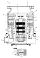
図1は、本実施の形態に係る磁気軸受装置を用いた分子ポンプ1の構成を示した図である。
ここで5軸制御型磁気軸受装置の構造例として分子ポンプ1の構造について説明する。なお、本実施の形態では、分子ポンプ1の一例としてターボ分子ポンプ部とねじ溝式ポンプ部を備えた、いわゆる複合翼タイプの分子ポンプを例に説明する。
FIG. 1 is a diagram showing a configuration of a molecular pump 1 using a magnetic bearing device according to the present embodiment.
Here, the structure of the molecular pump 1 will be described as an example of the structure of the 5-axis control type magnetic bearing device. In the present embodiment, as an example of the molecular pump 1, a so-called composite wing type molecular pump including a turbo molecular pump unit and a thread groove type pump unit will be described as an example.
分子ポンプ1の外装体を形成するケーシング2は、略円筒状の形状をしており、ケーシング2の底部に設けられた円盤状のベース3と共に分子ポンプ1の筐体を構成している。そして、ケーシング2の内部には、分子ポンプ1に排気機能を発揮させる構造物が収納されている。
これら排気機能を発揮する構造物は、大きく分けて回転自在に軸支されたロータ部4とケーシング2に対して固定されたステータ部から構成されている。
また、ポンプの種類から見た場合、吸気口5側がターボ分子ポンプ部により構成され、排気口6側がねじ溝式ポンプ部から構成されている。
The casing 2 forming the exterior body of the molecular pump 1 has a substantially cylindrical shape, and constitutes a housing of the molecular pump 1 together with a disc-shaped base 3 provided at the bottom of the casing 2. In the casing 2, a structure that allows the molecular pump 1 to perform an exhaust function is housed.
These structures that exhibit the exhaust function are roughly composed of a rotor portion 4 that is rotatably supported and a stator portion that is fixed to the casing 2.
Further, when viewed from the type of pump, the
ロータ部4は、モータによって回転されるシャフト7に配設された回転部材であり、吸気口5側(ターボ分子ポンプ部)に設けられたロータ翼8と、排気口6側(ねじ溝式ポンプ部)に設けられた円筒部材9、およびシャフト7などから構成されている。
シャフト7は、回転軸、つまり、ロータ部4の軸を構成する円柱部材であって、その上端部にはロータ翼8と円筒部材9からなる部材がボルト等により取り付けられている。
The rotor unit 4 is a rotating member disposed on a shaft 7 rotated by a motor, and includes a rotor blade 8 provided on the
The shaft 7 is a columnar member that constitutes the rotation axis, that is, the axis of the rotor portion 4, and a member composed of the rotor blade 8 and the cylindrical member 9 is attached to the upper end portion thereof by a bolt or the like.
シャフト7の軸線方向中程には、外周面に永久磁石が固着してあり、モータ部10のロータを構成している。この永久磁石がシャフト7の外周に形成する磁極は、外周面の半周に渡ってN極となり、残り半周に渡ってS極となるようになっている。
さらに、シャフト7のモータ部10に対して吸気口5側、および排気口6側には、シャフト7をラジアル方向(径方向)に軸支するための径方向磁気軸受装置11、12、シャフト7の下端には、シャフト7を軸線方向(アキシャル方向)に軸支するための軸方向磁気軸受装置13が設けられている。
In the middle of the shaft 7 in the axial direction, a permanent magnet is fixed to the outer peripheral surface, and the rotor of the
Further, on the
ケーシング2の内周側には、ステータ部が形成されている。このステータ部は、吸気口5側(ターボ分子ポンプ部)に設けられたステータ翼14と、排気口6側(ねじ溝式ポンプ)に設けられたねじ溝スペーサ18などから構成されている。
ターボ分子ポンプ部では、ステータ翼14が軸線方向に、ロータ翼8と互い違いに複数段形成されている。
各段のステータ翼14は、円筒形状をしたスペーサ15により互いに隔てられている。
A stator portion is formed on the inner peripheral side of the casing 2. This stator portion is composed of a
In the turbo molecular pump section, the
The
ねじ溝スペーサ18は、内周面にらせん溝16が形成された円柱部材である。ねじ溝スペーサの内周面は、所定のクリアランス(間隙)を隔てて円筒部材9の外周面に対面するようになっている。ねじ溝スペーサ18に形成されたらせん溝16の方向は、らせん溝16内をロータ部4の回転方向にガスが輸送された場合、排気口6に向かう方向である。
らせん溝16の深さは、排気口6に近づくにつれ浅くなるようになっており、らせん溝16を輸送されるガスは排気口6に近づくにつれて圧縮されるようになっている。
これらステータ部は、ステンレスやアルミニウム合金などの金属を用いて構成されている。
The
The depth of the
These stator portions are made of a metal such as stainless steel or aluminum alloy.
ベース3は、円盤形状を有した部材であって、ラジアル方向中央には、ロータの回転軸線と同心に円筒形状を有するステータコラム17が、吸気口5方向に取り付けられている。
ステータコラム17は、モータ部10、径方向磁気軸受装置11、12を支持している。
モータ部10では、所定の極数のステータコイルがステータコイルの内周側に等間隔で配設され、シャフト7に形成された磁極の周囲に回転磁界を発生できるようになっている。
The base 3 is a member having a disk shape, and a
The
In the
径方向磁気軸受装置11、12は、回転軸線の回りの90度ごとに配設された制御磁極部から構成されている。そして、径方向磁気軸受装置11、12は、これらコイルの発生する磁界でシャフト7を吸引することにより、シャフト7をラジアル方向に磁気浮上させている。この径方向磁気軸受装置11、12の詳細については後述する。
ステータコラム17の底部には、軸方向磁気軸受装置13が形成されている。軸方向磁気軸受装置13は、シャフト7から垂直に張り出した円板状のアーマチュア19と、このアーマチュア19の上下に配設されたコイルから構成されている。これらコイルが発生する磁界がアーマチュア19を吸引することにより、シャフト7が軸線方向に磁気浮上する。
The radial
An axial
上述したように、5軸制御型の磁気軸受装置には、軸方向の磁気浮上を制御する軸方向磁気軸受装置13と、径方向の磁気浮上を制御する径方向磁気軸受装置11、12とが設けられている。
そこで、本実施の形態に係る磁気軸受装置を軸方向磁気軸受装置13と、径方向磁気軸受装置11、12とに分けて説明する。
As described above, the 5-axis control type magnetic bearing device includes the axial
Therefore, the magnetic bearing device according to the present embodiment will be described separately for the axial
軸方向磁気軸受装置13は、図1に示すように、シャフト7に対して垂直に設けられたアーマチュア19を介してシャフト7を軸方向に浮上させるための装置である。
軸方向磁気軸受装置13は、軸方向電磁石が形成された一対の軸方向磁気軸受部20によって構成されている。
アーマチュア19には、軸方向磁気軸受部20の軸方向電磁石の磁力により、各軸方向磁気軸受部20方向に吸引される吸引力が作用する。
そして、軸方向磁気軸受装置13は、これらの吸引力を制御することによってアーマチュア19を介してシャフト7を軸方向に非接触状態で支持している。
As shown in FIG. 1, the axial
The axial
The
The axial
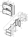
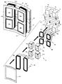
図2は、軸方向磁気軸受装置13を構成する軸方向磁気軸受部20の構成を示した図である。
軸方向磁気軸受部20は、軸方向電磁石部21と軸方向センサ部22とから構成されている。
軸方向電磁石部21は、アーマチュア19に対して吸引力を作用させるための磁力を発生させる電磁石を構成している。
FIG. 2 is a diagram showing the configuration of the axial
The axial
The
軸方向センサ部22は、アーマチュア19の変位、つまりシャフト7の軸方向の変位を検出する軸方向センサを構成する。
軸方向センサ部22では、アーマチュア19と軸方向磁気軸受部20との距離(ギャップ長)を検出することによってアーマチュア19の変位を認識している。
軸方向センサ部22では、インダクタンス形変位センサを用いてアーマチュア19の変位量を測定している。
なお、インダクタンス形変位センサとは、磁極に巻回されたコイルのインダクタンスが磁極のエアギャップと連動して変化する特性を利用し、インダクタンスの変化から変位を検出する変位センサである。
軸方向磁気軸受装置13には、一対の軸方向磁気軸受部20の軸方向センサ部22同士が互いに対面するように配置されている。
The axial
The
The
The inductance-type displacement sensor is a displacement sensor that detects a displacement from a change in inductance by using a characteristic that the inductance of a coil wound around the magnetic pole changes in conjunction with the air gap of the magnetic pole.
In the axial
軸方向電磁石部21は、第1軸方向電磁ヨーク23と軸方向電磁コイル24とから構成されている。
第1軸方向電磁ヨーク23は、軸方向電磁石部21の電磁石を形成する鉄心つまり電磁極を構成している。
第1軸方向電磁ヨーク23は、同心的な円孔が形成された円板部231、円板部231の周縁部を底面とする円筒状の外縁部232、円板部231に形成された円孔を底面とする円筒状の内縁部233とからなる。
The
The first axial
The first axial
円板部231を底面とした場合、内縁部233は、後述する第2軸方向電磁ヨーク25の高さ分だけ外縁部232よりも高くなっている。
第1軸方向電磁ヨーク23には、円板部231、外縁部232および内縁部233によって断面コの字型の溝234が形成されている。つまり溝234は、開放端部がアーマチュア19と対向するように設けられた環状溝である。
内縁部233の端面には、放射方向に延びる4つの溝235a〜dが、90度間隔に形成されている。
溝235a〜dによって内縁部233の端部は、4つの磁極部236a〜dに区分されている。
When the
The first axial
On the end face of the
The end portions of the
軸方向電磁コイル24は、内縁部233を軸芯として数ターン巻回された巻線である。軸方向電磁コイル24は、溝234の内部に配置されている。
従って、軸方向電磁コイル24の巻き上がりの最大外径寸法は、少なくとも外縁部232の内周の径寸よりも小さい。
軸方向電磁コイル24が通電状態になると、軸方向電磁コイル24の内部に電流が流れ磁束27が発生する。
すると、第1軸方向電磁ヨーク23が電磁石の磁極として機能し、軸方向電磁石部21に磁力が発生する。この磁力によってアーマチュア19に吸引力が作用するようになっている。
The axial
Accordingly, the maximum outer diameter dimension of the axial
When the axial
Then, the first axial
軸方向センサ部22は、第2軸方向電磁ヨーク25と軸方向センサコイル26とから構成されている。
第2軸方向電磁ヨーク25は、第1軸方向電磁ヨーク23と同様に軸方向電磁石部21の電磁石を形成する鉄心つまり電磁極を構成している。従って、第2軸方向電磁ヨーク25は、軸方向電磁コイル24が通電状態になると第1軸方向電磁ヨーク23と同様に電磁石の磁極として機能する。
第2軸方向電磁ヨーク25は、同心的な円孔が形成された円板部251、円板部251の周縁部を底面とする円筒状の外縁部252、円板部251に形成された円孔を底面とする円筒状の内縁部253とからなる。
なお、円板部251は、軸方向電磁コイル24の漏れ磁束が、軸方向センサコイル26に及ぼす影響を低減させるための遮蔽機能を担っている。
The
Similar to the first axial
The second axial
The
第1軸方向電磁ヨーク23と第2軸方向電磁ヨーク25とは、内縁部253の中空部に、第1軸方向電磁ヨーク23の内縁部233を嵌め込むようして組合せられている。
そのため、第2軸方向電磁ヨーク25の内縁部253の内径は、少なくとも第1軸方向電磁ヨーク23の内縁部233の外径よりも大きい。
内縁部253および外縁部252の高さは、第1軸方向電磁ヨーク23と第2軸方向電磁ヨーク25とを組み合わせた際に、第1軸方向電磁ヨーク23の内縁部233の端面の高さと等しくなっている。
The first axial
Therefore, the inner diameter of the
The height of the
第2軸方向電磁ヨーク25には、円板部251、外縁部252および内縁部253によって断面コの字型の溝254が形成されている。
内縁部253の端面には、放射方向に延びる4つの溝255a〜dが、90度間隔に設けられている。
溝255a〜dによって内縁部253の端部は、4つの磁極部256a〜dに分割されている。
なお、第1軸方向電磁ヨーク23と第2軸方向電磁ヨーク25とを組み合わせた場合、溝255a〜dは、溝235a〜dの放射方向の延長線上に配置されている。ここでは、溝255aの延長上に溝235a、溝255bの延長上に溝235b、溝255cの延長上に溝235c、溝255dの延長上に溝235dが設けられている。
In the second axial
On the end surface of the
The end portions of the
When the first axial
軸方向センサコイル26は、コイル261a〜dから構成されている。
コイル261aは、磁極部236aと磁極部256aの2つの磁極部を軸芯として、つまり磁極部236aと磁極部256aに渡って数ターン巻回された巻線である。
コイル261aは、磁極部236aと磁極部256aの側面に形成されている溝235a、235b、255a、255b、磁極部236aの内側面、磁極部256aの外側面に配置されるように巻回されている。
コイル261b〜dもコイル261aと同様の構成である。
なお、図中のコイル261a〜dに記されている極性は、コイル261a〜dが巻回される磁極部の端部に生じる極性の一例を示したものである。
The
The
The
The
Note that the polarities described in the
軸方向センサコイル26のコイル261a〜dは、全て並列に接続されている。
軸方向センサコイル26は、高周波電流が通電されることによって磁束28が発生し、第2軸方向電磁ヨーク25を伴って、軸方向変位センサを構成する。
コイル261a〜dに高周波電流が流れると各磁極部236a〜dおよび磁極部256a〜dが軸方向変位センサの磁極として作用する。つまり各磁極部236a〜dおよび磁極部256aに磁極が形成される。すると、各磁極部236a〜dおよび磁極部256aにおいて磁束28が発生する。
インダクタンス形の軸方向変位センサは、この磁束28の変化量を検出することによってアーマチュア19の変位つまりシャフト7の軸方向の変位を検出する。
The
The
When a high frequency current flows through the
The inductance type axial displacement sensor detects the displacement of the
本実施の形態では、軸方向センサコイル26を溝235a〜dおよび溝255a〜dによって4つに区分された部分に配置するようにしている。軸方向センサコイル26は、一対のコイルによって磁路を形成することが可能な範囲において、2区分、6区分等、即ち偶数部に区分された磁極部に軸方向センサコイル26を配置して変位センサコイルを構成するようにしてもよい。
In the present embodiment, the
次に、軸方向磁気軸受部20の変形例について説明する。
図3は、軸方向磁気軸受部20の変形例を示した図である。
なお、上述した図2に示す実施の形態と同一部分(重複する箇所)には、同一の符号を用い詳細な説明を省略する。
第1軸方向電磁ヨーク23’の外縁部232’および内縁部233に放射方向に延びる4つの溝237a〜dを90度間隔に形成する。溝237a〜dによって、外縁部232および内縁部233の先端部は、4つの磁極部238a〜dに分割される。
そして、コイル261aを、磁極部238aと磁極部236aの2つの磁極部を軸芯として、つまり磁極部238aと磁極部236aに渡ってを巻回す。コイル261b〜dもコイル261aと同様に構成されている。
Next, a modified example of the axial
FIG. 3 is a view showing a modification of the axial
In addition, the same code | symbol is used for the same part (overlapping part) as embodiment shown in FIG. 2 mentioned above, and detailed description is abbreviate | omitted.
Four
Then, the
このように、第1軸方向電磁ヨーク23’の内縁部233と外縁部232’に直接軸方向センサコイル26を巻回すことにより、第2軸方向電磁ヨーク25を設けることなく軸方向センサコイル26を配設することができる。
この場合、軸方向電磁コイル24の漏れ磁束の影響を抑制するために、軸方向電磁コイル24と軸方向センサコイル26との間にシールド部材29を配置するようにする。
図3に示すように、シールド部材29は、円環状のシールド部291とシールド部292から構成されている。
シールド部291は、第1軸方向電磁ヨーク23’の外縁部232’に沿うように配置されている。また、シールド部291には、溝237a〜dに沿うように方形の遮蔽部291a〜dがシールド部291の内周から中心方向へ延びるように設けられている。
シールド部292は、第1軸方向電磁ヨーク23’の内縁部233の内周に沿うように配置されている。
シールド部材29としては、例えば、銅などの金属板または金属泊、金属粉等を固化した部材などを用いることが好ましい。
このように、シールド部材29を円環状(短絡環状)のシールド部291とシールド部292を構成することによって、鎖交する磁束(漏れ磁束等)を短絡電流として消費させることができる。
Thus, the
In this case, a
As shown in FIG. 3, the
The
The
As the
In this way, by forming the
従来の軸方向センサは、シャフト7の下端付近に配置されていた。
詳しくは、軸方向センサは、シャフト7の下端に取り付けられたフェライトなどの磁性体からなるターゲットと、ベース3側のターゲットと対向する位置に設けられたのセンサコイルから構成されていた。そして、ターゲットとセンサコイルにおけるインダクタンスの変化を検出することによって、シャフト7の軸方向の変位を検出していた。
センサのインダクタンスの変化量とエアギャップの変化量の関係は、非線形であり、エアギャップが小さくなる程、インダクタンスの変化量が急激に増加する特性を有している。
そのため、適正な感度を得るためには、エアギャップを特定の範囲において、高い精度で調整する必要があった。これを実現させるためには、高精度の部品の使用、調整精度の向上等が要求されるためコストの低減が困難であった。
そこで、本実施形態では、アーマチュア19を挟み込むように、2つのセンサコイルを対向させて配置するようにしている。このように配置したセンサコイルにおいて、従来と同様の差動構成を用いることにより、センサのインダクタンスの変化量とエアギャップの変化量の関係の非線形特性が緩和されて、線形特性に近づく。従って、エアギャップを高精度で調整する必要がなくなるためセンサの位置調整が不要となる。
The conventional axial sensor has been arranged near the lower end of the shaft 7.
Specifically, the axial sensor is composed of a target made of a magnetic material such as ferrite attached to the lower end of the shaft 7 and a sensor coil provided at a position facing the target on the base 3 side. And the displacement of the axial direction of the shaft 7 was detected by detecting the change of the inductance in a target and a sensor coil.
The relationship between the change amount of the inductance of the sensor and the change amount of the air gap is non-linear, and has a characteristic that the change amount of the inductance increases rapidly as the air gap becomes smaller.
Therefore, in order to obtain appropriate sensitivity, it is necessary to adjust the air gap with high accuracy in a specific range. In order to realize this, it is difficult to reduce costs because it is required to use high-precision parts, improve adjustment accuracy, and the like.
Therefore, in the present embodiment, the two sensor coils are arranged to face each other so as to sandwich the
また、本実施の形態によれば、ロータ軸の変位、具体的にはアーマチュア19の変位の検出を、対象物に近接した位置で行うことができるため、変位センサの検出感度を向上させることができる。
さらに、このように第1軸方向電磁ヨーク23または第2軸方向電磁ヨーク25に軸方向センサコイル26を配置することにより、軸方向電磁石を作用させる磁極を軸方向センサと共用することができる。
これにより軸方向センサによる対象物の検出点と、軸方向磁気軸受の電磁石の作用点とを一致させることができるため、軸方向磁気軸受装置13の制御精度を向上させることができる。
Further, according to the present embodiment, the displacement of the rotor shaft, specifically the displacement of the
Furthermore, by arranging the
As a result, the detection point of the object by the axial sensor and the action point of the electromagnet of the axial magnetic bearing can be matched, so that the control accuracy of the axial
次に、径方向磁気軸受装置11、12の詳細について説明する。
図4は、本実施の形態に係る径方向磁気軸受装置11、12の断面図を示した図である。なお、径方向磁気軸受装置11および径方向磁気軸受装置12は、同一構造であるため、ここでは、径方向磁気軸受装置11の構造について説明する。
径方向磁気軸受装置11には、4つの制御磁極部31a〜dが回転軸線の回りに90度間隔に配設されている。
各制御磁極部31a〜dは、シャフト7と同心の円筒状の環状鉄心30の内周壁に設けられた鉄心片32と鉄心片33とが対となった鉄心対を備えている。環状鉄心30、鉄心片32および鉄心片33は、磁性体の部材によって構成されている。
磁性体部材としては、例えば、積層珪素鋼板やフェライトなどが用いられている。
Next, details of the radial
FIG. 4 is a cross-sectional view of the radial
In the radial
Each of the control
As the magnetic member, for example, a laminated silicon steel plate or ferrite is used.
鉄心片32および鉄心片33は電磁極であり、径方向電磁コイル34が巻回されている。そして、径方向電磁コイル34に通電することによって鉄心片32および鉄心片33は磁化されそれぞれ異なる極性を有する磁極となり、シャフト7を吸引する吸引力を作用させる電磁石の磁極として作用する。
鉄心片32および鉄心片33の先端部には両鉄心片に渡って径方向センサコイル36が巻回されている。そして、径方向センサコイル36に通電することによって鉄心片32および鉄心片33は、シャフト7の変位を検出する径方向変位センサとしても作用する。
径方向電磁コイル34と径方向センサコイル36との間には、シールド板35が設けられている。
なお、制御磁極部31a〜dの詳細については後述する。
The
A
A
Details of the control
シャフト7は、制御磁極部31bによってX軸方向の正方向に、制御磁極部31dによってX軸の負方向に吸引し、さらに、制御磁極部31aによってY軸方向の正方向に、制御磁極部31cによってY軸の負方向に吸引されている。
このようにしてシャフト7と制御磁極部31a〜dとのギャップ長(隙間距離)が均一となるように電磁石の磁力を制御することによってシャフト7を径方向に非接触状態で支持している。
なお、シャフト7と制御磁極部31a〜dとのギャップ長の変位は、径方向変位センサによって検出する。
The shaft 7 is attracted in the positive direction in the X-axis direction by the control
Thus, the shaft 7 is supported in a non-contact state in the radial direction by controlling the magnetic force of the electromagnet so that the gap length (gap distance) between the shaft 7 and the control
Note that the displacement of the gap length between the shaft 7 and the control
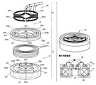
図5は、制御磁極部31a〜dの構成を示した図である。
なお、制御磁極部31a〜dは、全て同一構造であるため、ここでは、制御磁極部31aの構造について説明する。
制御磁極部31aは、径方向磁極部43、径方向電磁コイル34、シールド板35、および径方向センサコイル36によって構成されている。
径方向磁極部43には、矩形状の鉄心片32および鉄心片33が、環状鉄心30の内周壁からシャフト7の方向に突出するように、隣接して形成されている。
鉄心片32および鉄心片33は、軸方向に延びた矩形状の磁性体の部材によって形成されている。
FIG. 5 is a diagram showing the configuration of the control
Since the control
The control
A rectangular
The
鉄心片32および鉄心片33には、軸方向の中心部に1本の溝37、38がそれぞれ円周方向に延びる向きに設けられている。
溝37によって鉄心片32は、磁極部39と磁極部40に分割され、同様に、溝38によって鉄心片33は、磁極部41と磁極部42に分割されている。
なお、磁極部39〜42の先端部のシャフト7と対向する面を磁極面39a、40a、41a、42aとする。
The
The
In addition, let the surface which opposes the shaft 7 of the front-end | tip part of the magnetic pole parts 39-42 be
径方向電磁コイル34は、コイル34aおよびコイル34bから構成されている。
コイル34aは、鉄心片32を軸芯として数ターン巻回され、また。コイル34bは、鉄心片33を軸芯として数ターン巻回されている。
なお、コイル34aおよびコイル34bは、並列に接続されている。
このようにして、径方向電磁コイル34は径方向磁極部43に配置されている。
コイル34aおよびコイル34bに通電することによって鉄心片32および鉄心片33は磁化されそれぞれ異なる極性を有する磁極となり、シャフト7を吸引する吸引力を作用させる電磁石の磁極として作用する。
The radial
The
The
In this way, the radial
When the
シールド板35は、径方向電磁コイル34の漏れ磁束をシールド(遮断)するための電磁遮蔽板である。シールド板35を設けることにより径方向電磁コイル34から発生する磁束が他の部分に及ぼす影響を低減させることができる。
シールド板35は、導体板または導体網などで形成され、磁気軸受装置に設けられた制御回路のグラウンドレベルの電位に接地されている。
シールド板35は、鉄心片32、33を囲むように形成された、縁部に切れ目がない一続きの環状の部材によって構成されている。つまり、外縁部が短絡された部材によって構成されている。
つまりシールド板35は、ショートリング(短絡環)を構成することによって、鎖交する磁束(漏れ磁束等)を短絡電流として消費させることができるようになっている。
The
The
The
That is, the
シールド板35の内縁は、鉄心片32、33の側面に沿った形状となっている。さらに、シールド板35には、鉄心片32と鉄心片33との隙間に沿うように外縁部から中央方向に延びた方形の遮蔽部35a、35bが設けられている。
このように遮蔽部35a、35bを設けることにより鉄心片32と鉄心片33との間から漏れる磁束を適切に遮蔽することができる。
シールド板35は、例えば銅箔や銅板などによって形成されることが望ましく、強度の高い磁束を遮蔽する場合には、これらの部材を数枚重ねて用いるようにする。
The inner edge of the
Thus, by providing the
The
径方向センサコイル36は、コイル36aおよびコイル36bから構成されている。
コイル36aは、磁極部39と磁極部41の2つの磁極部を軸芯として、つまり磁極部39と磁極部41に渡って数ターン巻回されている。
コイル36bは、磁極部40と磁極部42の2つの磁極部を軸芯として、つまり磁極部40と磁極部42に渡って数ターン巻回されている。コイル36a、36bは、溝37、38に配置されるように巻回されている。
従って、コイル36aおよびコイル36bの両巻線は、それぞれ共通の溝37、38を用いて各磁極部39〜42の側面に配置されている。
なお、コイル36aおよびコイル36bは、並列に接続されている。
The
The
The
Therefore, both windings of the
The
コイル36a、36bは、磁極部39〜42の先端部分に配置されている。磁極部39〜42上の径方向センサコイル36の配置部分と径方向電磁コイル34の配置部分とは重複しないように配置されている。
なお、シールド板35は、径方向センサコイル36と径方向電磁コイル34との間に配置されている。
The
The
このようにして、径方向センサコイル36は、シールド板35を介して径方向電磁コイル34が配置された径方向磁極部43に配置されている。
径方向センサコイル36は、高周波電流が通電されることによって磁束が発生し、磁極部39〜42を伴って、径方向変位センサを構成する。
コイル36a、36bに高周波電流が流れると各磁極部39〜42が径方向変位センサの磁極として作用する。つまり各磁極部39〜42に磁極が形成される。すると、各磁極部39〜42において磁束が発生する。
In this way, the
The
When a high frequency current flows through the
インダクタンス形の径方向変位センサは、この磁束の変化量を検出することによってシャフト7の軸方向の変位を検出する。
径方向センサコイル36に高周波電流が流れることによって、磁極部39〜42の表面にうず電流が発生し損失が増加してしまう。
このうず電流の発生を抑制するために、磁極部39〜42の磁極面39a、40a、41a、42aに軸方向に延びる溝(スリット)を、磁極面39a、40a、41a、42aの軸方向の磁極面に放射方向に延びる溝(スリット)を設けている。
また、このようなスリット加工を施す代わりに、磁極部39〜42つまり鉄心片32と鉄心片33を鉄粉を焼結させて形成された部材を用いるようにしてもよい。
なお、本実施の形態に係る径方向磁気軸受装置11、12の磁極の極性の詳細については、後述する。
The inductance-type radial displacement sensor detects the axial displacement of the shaft 7 by detecting the amount of change in the magnetic flux.
When a high-frequency current flows through the
In order to suppress the generation of this eddy current, grooves (slits) extending in the axial direction are formed on the
Moreover, you may make it use the member formed by sintering the magnetic pole parts 39-42, ie, the
The details of the polarities of the magnetic poles of the radial
本実施の形態によれば、径方向電磁コイル34と径方向センサコイル36を溝37、38を用いて鉄心片32、33上に配置することにより、鉄心片32、33を電磁石の磁極と径方向変位センサの磁極と共用することができる。つまり、電磁石の磁極を同時に径方向変位センサの磁極として用いることができる。従って、径方向変位センサを専用の磁極を別に設けることなく構成することができる。
According to the present embodiment, by arranging the radial
本実施の形態では、吸引力をシャフト7に作用させるための電磁石の磁極32、33の溝37、38を除く全ての部分を径方向変位センサの磁極と共用している。そのため、変位センサに用いられる磁極39〜42の磁極面39a、40a、41a、42aの面積を十分に確保することができる。
径方向変位センサに対して、このように広い磁極面を確保することができるため、センサの検出感度を高めることが容易にできる。さらに、広い磁極面を確保することにより、磁極39〜42が飽和しにくくなり、径方向変位センサの検出感度の調整範囲を拡大することができる。
In the present embodiment, all portions except for the
Since such a wide magnetic pole surface can be ensured for the radial displacement sensor, the detection sensitivity of the sensor can be easily increased. Furthermore, by ensuring a wide magnetic pole surface, the
また、このように広い磁極面を確保することにより、径方向磁気軸受部に各磁極39〜42のばらつき(磁極面積や磁極体積などのばらつき)が存在しても、十分にその誤差を吸収することができる。つまり、これらのばらつきを無視することが可能な程度にまで抑えることができる。
In addition, by securing such a wide magnetic pole surface, even if there are variations in the
さらに、このように広い磁極面を確保することにより、所定のインダクタンスを得るための径方向センサコイル36の巻数を低減させることができる。径方向センサコイル36の巻数を減らすことにより、径方向センサコイル36をシート状のプリント基板、例えばフレキシブル基板に形成することができる。これにより、製造工程の削減を図ることが可能となる。
Furthermore, by securing such a wide magnetic pole surface, the number of turns of the
本実施の形態によれば、吸引力をシャフト7に作用させるための電磁石の磁束と径方向変位センサの磁束とが異なる方向に発生するためそれぞれの磁束が干渉しないようにすることができる。
詳しくは、径方向電磁コイル34により発生する磁束は、シャフト7を経由し鉄心片32と鉄心片33の間を流れる。それに対し、径方向センサコイル36は、鉄心片と32と鉄心片33をまたぐように配置されている。径方向センサコイル36には、径方向電磁コイル34により発生する磁束が鎖交しない。そのため、径方向電磁コイル34により発生する磁束がノイズとして径方向センサコイル36に混入することがない。
つまり、変位センサコイルに入る電磁石の磁束と出る磁束の値がほぼ一致する。従って、電磁石の磁束が径方向変位センサの磁束にほとんど重畳することがないため、電磁石の磁束の影響を受けることなく径方向変位センサを作用させることが可能となる。
According to the present embodiment, since the magnetic flux of the electromagnet for causing the attractive force to act on the shaft 7 and the magnetic flux of the radial displacement sensor are generated in different directions, the respective magnetic fluxes can be prevented from interfering with each other.
Specifically, the magnetic flux generated by the radial
That is, the value of the magnetic flux of the electromagnet entering the displacement sensor coil and the value of the magnetic flux exiting are substantially the same. Therefore, since the magnetic flux of the electromagnet hardly overlaps the magnetic flux of the radial displacement sensor, the radial displacement sensor can be operated without being affected by the magnetic flux of the electromagnet.
また、本実施の形態によれば、径方向センサコイル36を構成するコイル36aおよびコイル36bを並列に接続されている。
ここで、コイル36aとコイル36bの巻き数を共にN、端子電圧をEa、Eb、磁束をφa、φb、時間をtと仮定すると、Ea=Ndφa/dt、Eb=Ndφb/dtの関係が成り立つ。両コイルは並列接続されているので、Ea=Ebとなる。従って、dφa=dφbとなり、コイル36aとコイル36bの磁束の変化量が等しくなる。このため、コイル36の磁束が他のコイルへ干渉することを抑制することができる。
このように、径方向センサコイル36を構成するコイル36aおよびコイル36bを並列に接続することにより、変位センサの磁束が他に及ぼす影響を低減させることができ、径方向磁気軸受装置11、12の精度を向上させることができる。
Moreover, according to this Embodiment, the
Here, assuming that the number of turns of the
Thus, by connecting the
次に、制御磁極部31a〜dの変形例1〜3について説明する。
(変形例1)
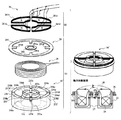
図6は、制御磁極部31aの変形例1の構成を示した図である。
なお、上述した図5に示す実施の形態と同一部分(重複する箇所)には、同一の符号を用い詳細な説明を省略する。
制御磁極部31a(変形例1)は、径方向磁極部50、径方向電磁コイル34、シールド板35および径方向センサコイル58によって構成されている。
Next, modified examples 1 to 3 of the control
(Modification 1)
FIG. 6 is a diagram showing a configuration of Modification 1 of the control
In addition, the same code | symbol is used for the same part (overlapping location) as Embodiment shown in FIG. 5 mentioned above, and detailed description is abbreviate | omitted.
The control
径方向磁極部50は、環状スペーサ57、環状鉄心30を円周方向に2分割した環状鉄心51および環状鉄心52によって構成されている。
環状スペーサ57は、非磁性体の円環状の部材によって形成され、環状鉄心51と環状鉄心52とによって挟持されている。
環状スペーサ57を形成する非磁性体の部材としては、例えば、アルミニウムや強化プラスチックなどが用いられている。
環状鉄心51には、内周壁からシャフト7の方向に突出するように、矩形状の磁極部53および磁極部54が隣接して形成されている。
同様に環状鉄心52には、内周壁からシャフト7の方向に突出するように、矩形状の磁極部55および磁極部56が隣接して形成されている。
なお、磁極部53〜56の先端部のシャフト7と対向する面を磁極面53a、54a、55a、56aとする。
The radial
The
As the nonmagnetic member forming the
A rectangular
Similarly, a rectangular
In addition, let the surface which opposes the shaft 7 of the front-end | tip part of the magnetic pole parts 53-56 be the
径方向電磁コイル34は、コイル34aおよびコイル34bから構成されている。
コイル34aは、磁極部53と磁極部55の2つの磁極部を軸芯として、つまり磁極部53と磁極部55に渡って数ターン巻回されている。磁極部53と磁極部55によってコイル34aが巻回される電磁極が構成されている。
コイル34bは、磁極部54と磁極部56の2つの磁極部を軸芯として、つまり磁極部54と磁極部56に渡って数ターン巻回されている。磁極部54と磁極部56によってコイル34bが巻回される電磁極が構成されている。
なお、コイル34aおよびコイル34bは、並列に接続されている。
このようにして、径方向電磁コイル34は径方向磁極部50に配置されている。
コイル34aおよびコイル34bに通電することによって磁極部53、55および磁極部54、56は、磁化されそれぞれ異なる極性を有する磁極となり、シャフト7を吸引する吸引力を作用させる電磁石の磁極として作用する。
The radial
The
The
The
In this way, the radial
By energizing the
シールド板35は、導体板または導体網などで形成された電磁遮蔽板であり、図5で示した実施の形態で用いたものと同様のシールド板35によって構成されている。
シールド板35の内縁は、磁極部53〜56の側面に沿った形状となっている。さらに、シールド板35には、磁極部53と磁極部54、磁極部55と磁極部56との隙間に沿うように中央方向に延びた方形の遮蔽部35a、35bが設けられている。
このように遮蔽部35a、35bを設けることにより磁極部53と磁極部54、磁極部55と磁極部56との間から漏れる磁束を適切に遮蔽することができる。
The
The inner edge of the
By providing the
径方向センサコイル58は、コイル58a、コイル58b、コイル58cおよびコイル58dから構成されている。
コイル58aは、磁極部53を軸芯として数ターン巻回されている。
同様に、コイル58bは磁極部55、コイル58cは磁極部54、コイル58dは磁極部56を軸芯として数ターン巻回されている。
なお、コイル58a、コイル58b、コイル58cおよびコイル58dは、全て並列に接続されている。
コイル58a、コイル58b、コイル58cおよびコイル58dは、磁極部53〜56の先端部分に配置されている。磁極部53〜56上の径方向センサコイル36の配置部分と径方向電磁コイル34の配置部分とは重複しないように配置されている。
なお、シールド板35は、径方向センサコイル58と径方向電磁コイル34との間に配置されている。
The
The
Similarly, the
The
The
The
(変形例2)
図7は、制御磁極部31aの変形例2の構成を示した図である。
なお、上述した図5に示す実施の形態または変形例1と同一部分(重複する箇所)には、同一の符号を用い詳細な説明を省略する。
制御磁極部31a(変形例2)は、径方向磁極部50、径方向センサコイル58、シールド部61、径方向電磁コイル34、およびシールド板62によって構成されている。
(Modification 2)
FIG. 7 is a diagram showing a configuration of Modification 2 of the control
In addition, the same code | symbol is used for the same part (overlapping location) as Embodiment or the modification 1 shown in FIG. 5 mentioned above, and detailed description is abbreviate | omitted.
The control
径方向磁極部50は、変形例1と同一の構造である。
径方向センサコイル58は、コイル58a、コイル58b、コイル58cおよびコイル58dから構成されている。コイル58aは、磁極部53を軸芯として数ターン巻回されている。
同様に、コイル58bは磁極部55、コイル58cは磁極部54、コイル58dは磁極部56を軸芯として数ターン巻回されている。
このようにして、径方向センサコイル58は径方向磁極部50に配置されている。
なお、変形例2では、コイル58a、コイル58b、コイル58cおよびコイル58dの配置場所は、磁極部53〜56の先端部に限定されるものではなく、磁極部53〜56の側面の任意の場所に配置するようにしてもよい。例えば、磁極部53〜56の側面の中央部、または側面の全域に渡るように配置するようにしてもよい。
The radial
The
Similarly, the
In this manner, the
In the second modification, the arrangement location of the
シールド部61は、シールドリング61a、61b、61cおよび61dから構成されている。
シールドリング61a、61b、61cおよび61dは、径方向センサコイル58から漏れる磁束をシールドするための電磁遮蔽部材であり、帯状のシールド効果の高い金属板(例えば銅板)を加工した部材によって形成されている。なお、帯状のシールドリングの巻きはじめと巻き終わりの端部は、重なり合うようになっているが、電気的には接触していない。
シールドリング61aは、巻回されたコイル58aを覆うように磁極部53の側面に配置されている。
同様に、シールドリング61bはコイル58bを覆うように磁極部55の側面、シールドリング61cはコイル58cを覆うように磁極部54の側面、シールドリング61dはコイル58dを覆うように磁極部56の側面に配置されている。
The shield part 61 is composed of
The shield rings 61a, 61b, 61c and 61d are electromagnetic shielding members for shielding magnetic flux leaking from the
The shield ring 61a is disposed on the side surface of the
Similarly, the shield ring 61b covers the
また、シールドリング61a、61b、61cおよび61dは、金属板を加工した部材を用いるようにしているが、金属板の代わりに金属箔(銅箔)を用いるようにしてもよい。
このような金属箔を用いた場合、形状の変形や加工は容易になるが、部材が大変薄いため十分なシールド効果を得るために複数重ねて配置するようにする。
Moreover, although the
When such a metal foil is used, the shape can be easily deformed and processed. However, since the member is very thin, a plurality of layers are arranged in order to obtain a sufficient shielding effect.
径方向電磁コイル34は、コイル34aおよびコイル34bから構成されている。
コイル34aは、磁極部53と磁極部55の2つの磁極部を軸芯として、つまり磁極部53と磁極部55に渡って、シールドリング61a、61bを介して数ターン巻回されている。磁極部53と磁極部55によってコイル34aが巻回される電磁極が構成されている。
コイル34bは、磁極部54と磁極部56の2つの磁極部を軸芯として、つまり磁極部54と磁極部56に渡って、シールドリング61c、61dを介して数ターン巻回されている。磁極部54と磁極部56によってコイル34bが巻回される電磁極が構成されている。
なお、コイル34aおよびコイル34bは、並列に接続されている。
The radial
The
The
The
このようにして、径方向電磁コイル34は、径方向センサコイル58およびシールド部61を介して径方向磁極部50に配置されている。
径方向電磁コイル34と径方向センサコイル58との間にシールド部61を介することにより、径方向電磁コイル34と径方向センサコイル58の両コイルを磁極部53〜56の先端部に配置することが可能になる。これにより、径方向磁気軸受装置11、12の制御精度を向上させることができる。
また、径方向電磁コイル34と径方向センサコイル58との間にシールド部61を介することにより、径方向電磁コイル34と径方向センサコイル58の両コイルの配置位置が制限されることがない、つまり、両コイルを任意の位置に配置することができるため、設計の自由度を向上させることができる。
コイル34aおよびコイル34bに通電することによって磁極部53、55および磁極部54、56は、磁化されそれぞれ異なる極性を有する磁極となり、シャフト7を吸引する吸引力を作用させる電磁石の磁極として作用する。
In this way, the radial
By disposing a shield portion 61 between the radial
Further, by arranging the shield part 61 between the radial
By energizing the
シールド板62は、導体板または導体網などで形成された電磁遮蔽板であり、磁気軸受装置に設けられた制御回路のグラウンドレベルの電位に接地されている。
シールド板62は、磁極部53〜56を囲むように形成された、縁部に切れ目がない一続きの環状の部材によって構成されている。外縁部が短絡された部材によって構成されている。つまり、シールド板62の内縁は、磁極部53〜56の側面に沿った形状となっている。
即ち、シールド板62によってショートリング(短絡環)を構成することにより、鎖交する磁束(漏れ磁束等)を短絡電流として消費させることができるようになっている。
The
The
That is, by forming a short ring (short-circuit ring) with the
このようにシールド板62を磁極部53〜56の先端部に配置することにより、漏れ磁束がシャフト7に及ぼす影響を低減させることができる。
シールド板62は、例えば銅箔や銅板などによって形成されることが望ましく、強度の高い磁束を遮蔽する場合には、これらの部材を数枚重ねて用いるようにする。
By arranging the
The
(変形例3)
図8は、制御磁極部31aの変形例3の構成を示した図である。
なお、上述した図5に示す実施の形態または変形例1、2と同一部分(重複する箇所)には、同一の符号を用い詳細な説明を省略する。
制御磁極部31a(変形例3)は、径方向磁極部70、径方向電磁コイル34、シールド板72径方向およびセンサコイル36によって構成されている。
(Modification 3)
FIG. 8 is a diagram showing a configuration of Modification 3 of the control
In addition, the same code | symbol is used for the same part (overlapping part) as Embodiment or the modification 1, 2 shown in FIG. 5 mentioned above, and detailed description is abbreviate | omitted.
The control
径方向磁極部70は、環状スペーサ57、環状鉄心30を円周方向に2分割した環状鉄心51および環状鉄心52、磁性部材71、72によって構成されている。
環状スペーサ57は、非磁性体の円環状の部材によって形成され、環状鉄心51と環状鉄心52とによって挟持されている。
環状鉄心51には、内周壁からシャフト7の方向に突出するように、矩形状の磁極部53および磁極部54が隣接して形成されている。
同様に環状鉄心52には、内周壁からシャフト7の方向に突出するように、矩形状の磁極部55および磁極部56が隣接して形成されている。
The radial magnetic pole portion 70 includes an
The
A rectangular
Similarly, a rectangular
磁性部材71は、磁性体の矩形状の部材によって形成され、磁極部53と磁極部55とによって挟持されている。
同様に、磁性部材72は、磁性体の矩形状の部材によって形成され、磁極部54と磁極部56とによって挟持されている。
磁性部材71、72は、例えば、積層珪素鋼板やフェライトなどで形成されている。
なお、磁極部53〜56の先端部のシャフト7と対向する面を磁極面53a、54a、55a、56aとする。
The
Similarly, the magnetic member 72 is formed of a rectangular member made of a magnetic material, and is sandwiched between the
The
In addition, let the surface which opposes the shaft 7 of the front-end | tip part of the magnetic pole parts 53-56 be the
径方向電磁コイル34は、コイル34aおよびコイル34bから構成されている。
コイル34aは、磁極部53と磁極部55の2つの磁極部を軸芯として、つまり磁極部53と磁極部55に渡って数ターン巻回されている。磁極部53と磁極部55によってコイル34aが巻回される電磁極が構成されている。
コイル34bは、磁極部54と磁極部56の2つの磁極部を軸芯として、つまり磁極部54と磁極部56に渡って数ターン巻回されている。磁極部54と磁極部56によってコイル34aが巻回される電磁極が構成されている。
なお、コイル34aおよびコイル34bは、並列に接続されている。
このようにして、径方向電磁コイル34は径方向磁極部70に配置されている。
コイル34aおよびコイル34bに通電することによって磁極部53、55および磁極部54、56は、磁化されそれぞれ異なる極性を有する磁極となり、シャフト7を吸引する吸引力を作用させる電磁石の磁極として作用する。
The radial
The
The
The
In this manner, the radial
By energizing the
シールド板72は、径方向電磁コイル34の漏れ磁束をシールド(遮断)するための電磁遮蔽板である。シールド板72を設けることにより径方向電磁コイル34から発生する磁束が他の部分に及ぼす影響を低減させることができる。
シールド板35は、導体板または導体網などで形成され、磁気軸受装置に設けられた制御回路のグラウンドレベルの電位に接地されている。
シールド板72は、磁極部53〜56を囲むように形成された、縁部に切れ目がない一続きの環状の部材によって構成されている。
つまりシールド板72は、ショートリング(短絡環)を構成することによって、鎖交する磁束(漏れ磁束等)を短絡電流として消費させることができるようになっている。
The shield plate 72 is an electromagnetic shielding plate for shielding (blocking) the leakage magnetic flux of the radial
The
The shield plate 72 is configured by a continuous annular member that is formed so as to surround the
That is, the shield plate 72 constitutes a short ring (short-circuit ring), so that interlinkage magnetic flux (leakage magnetic flux or the like) can be consumed as a short-circuit current.
シールド板72の内縁は、磁極部53〜56の側面に沿った形状となっている。さらに、シールド板72には、磁極部53と磁極部55との隙間、および磁極部54と磁極部56との隙間に沿うように中央方向に延びた方形の遮蔽部72a、72bが設けられている。
このように遮蔽部72a、72bを設けることにより磁極部53と磁極部55との隙間、および磁極部54と磁極部56との隙間から漏れる磁束を適切に遮蔽することができる。
シールド板72は、例えば銅箔や銅板などによって形成されることが望ましく、強度の高い磁束を遮蔽する場合には、これらの部材を数枚重ねて用いるようにする。
The inner edge of the shield plate 72 has a shape along the side surfaces of the
Thus, by providing the
The shield plate 72 is desirably formed of, for example, a copper foil or a copper plate. When shielding a high-strength magnetic flux, several of these members are used.
径方向センサコイル36は、コイル36aおよびコイル36bから構成されている。
コイル36aは、磁極部53と磁極部54の2つの磁極部を軸芯として、つまり磁極部53と磁極部54に渡って数ターン巻回されている。
コイル36bは、磁極部55と磁極部56の2つの磁極部を軸芯として、つまり磁極部55と磁極部56に渡って数ターン巻回されている。
なお、コイル36aおよびコイル36bは、並列に接続されている。
The
The
The
The
コイル36a、36bは、磁極部53〜56の先端部分に配置されている。磁極部53〜56上の径方向センサコイル36の配置部分と径方向電磁コイル34の配置部分とは重複しないように配置されている。
なお、シールド板72は、径方向センサコイル36と径方向電磁コイル34との間に配置されている。
The
The shield plate 72 is disposed between the
このようにして、径方向センサコイル36は、シールド板72を介して径方向電磁コイル34が配置された径方向磁極部70に配置されている。
径方向センサコイル36は、高周波電流が通電されることによって磁束が発生し、磁極部53〜56を伴って、径方向変位センサを構成する。
コイル36a、36bに高周波電流が流れると各磁極部53〜56が径方向変位センサの磁極として作用する。つまり各磁極部53〜56に磁極が形成される。すると、各磁極部53〜456において磁束が発生する。
インダクタンス形の径方向変位センサは、この磁束の変化量を検出することによってシャフト7の軸方向の変位を検出する。
In this way, the
The
When a high frequency current flows through the
The inductance-type radial displacement sensor detects the axial displacement of the shaft 7 by detecting the amount of change in the magnetic flux.
このような径方向磁気軸受部の変形例1、変形例2および変形例3によれば、制御磁極部31aを構成する4つの磁極部を、磁極に溝を設けることなく単純な形状の部材によって構成することができるため、製造コストを低減させることができる。
特に、径方向磁気軸受装置では、珪素鋼板などによって磁極を構成することが多い。この珪素鋼板は、とても薄い部材であるため形状の加工時にバリや変形を起こしやすいが、このような単純な形状の磁極部によって磁極を構成することによりこのような不具合の発生を抑制することができる。
According to the first, second, and third modifications of the radial magnetic bearing portion, the four magnetic pole portions constituting the control
In particular, in a radial magnetic bearing device, the magnetic pole is often constituted by a silicon steel plate or the like. Since this silicon steel plate is a very thin member, it is easy to cause burrs and deformations when processing the shape, but by forming the magnetic pole with such a simple magnetic pole part, it is possible to suppress the occurrence of such problems. it can.
次に、本実施の形態に係る径方向磁気軸受装置11、12、および変形例1〜3に示す径方向磁気軸受装置11、12の制御磁極部31a〜dにおける磁極の極性にいて説明する。
図9は、図4に示すA−A’部において径方向磁気軸受装置11、12を展開した場合の各磁極の極性の状態を示した図である。なお、径方向磁気軸受装置11、12は、対象構造となっているため、ここでは、径方向磁気軸受装置11、12の半分について説明する。
Next, the polarity of the magnetic poles in the control
FIG. 9 is a diagram showing the polarity state of each magnetic pole when the radial
図9には、各磁極の先端部における磁極性のみを簡易的に示し、電磁石の極性については、上下段とも同一の極性を有しているため吸気口5の方向から見た展開図のみを示す。 また、変位センサの極性については、シャフト7の方向から見た展開図を記載している。なお、図5に示す本実施の形態を変形例1〜3と区別するために「代表形態」と示す。
図9では、径方向磁気軸受部の吸気口5側に設けられている磁極を上段、排気口6側に設けられている磁極を下段と表現する。
FIG. 9 simply shows only the magnetic polarity at the tip of each magnetic pole, and the polarity of the electromagnet has the same polarity in both the upper and lower stages, so only a development view seen from the direction of the
In FIG. 9, the magnetic pole provided on the
図9(a)は、本実施の形態に係る径方向磁気軸受装置11、12、および変形例3に示した径方向磁気軸受装置11、12における径方向磁気軸受部(以下「代表形態と変形例3」と示す)の各磁極の極性の状態を示した図である。
図9(b)は、変形例1および変形例2に示した径方向磁気軸受装置11、12における径方向磁気軸受部(以下「変形例1および変形例2」と示す)の各磁極の極性の状態を示した図である。
また、変位センサは、高周波電流によって駆動されているため、磁極は一定ではなく常に変化、つまり極性が入れ替わっている。そのため、図中では、ある時点における状態を示している。
9A shows the radial
FIG. 9B shows the polarities of the magnetic poles of the radial magnetic bearing portions (hereinafter referred to as “Modification 1 and Modification 2”) in the radial
Further, since the displacement sensor is driven by a high frequency current, the magnetic pole is not constant but always changes, that is, the polarity is switched. Therefore, the state at a certain time is shown in the figure.
図9(a)、(b)に示すように、本実施の形態に係る径方向磁気軸受装置11、12、および変形例1〜3に示した径方向磁気軸受装置11、12の制御磁極部31a〜dにおいては、電磁石は共通の磁極性の特性を有し、磁束の発生する向きつまり電磁石の磁路93および磁路94の形成される向きも同一となっている。
As shown in FIGS. 9A and 9B, the radial
一方、径方向変位センサの磁極特性は、図9(a)と(b)とで異なる特性を有し、磁束の発生する向きつまり磁路の形成される向きもことなっている。
図9(a)に示すように、代表形態と変形例3における径方向変位センサは、各段における磁極性が同一になるようにコイルが巻回されている。そして、上段と下段は、常に異なる磁極性を有し、変位センサの磁束は、上下方向に隣接する磁極間に径方向変位センサの磁路95〜98が形成されるように発生するようになっている。
なお、変形例3においては、磁極間に介在している磁性部材71、72を介して磁路95〜98が形成されるようになっている。
図9(b)に示すように、変形例1と変形例2における変位センサは、上下方向に隣接する磁極の極性が、常に異なるようにコイルが巻回されている。そして、変位センサの磁束は、同一段上の隣接する磁極間に磁路99〜102が形成されるように発生するようになっている。
On the other hand, the magnetic pole characteristics of the radial displacement sensor have different characteristics in FIGS. 9A and 9B, and the direction in which the magnetic flux is generated, that is, the direction in which the magnetic path is formed, is also different.
As shown to Fig.9 (a), the coil is wound so that the magnetic pole property in each step may become the same in the radial direction displacement sensor in a representative form and the modification 3. FIG. The upper and lower stages always have different magnetic polarities, and the magnetic flux of the displacement sensor is generated so that the
In the third modification,
As shown in FIG. 9B, in the displacement sensors in the first and second modifications, the coils are wound so that the polarities of the magnetic poles adjacent in the vertical direction are always different. The magnetic flux of the displacement sensor is generated so that
上述した変形例1および変形例2においては、径方向センサコイル58をコイル58a、58b、58c、58dによって構成し、これらの4つのコイルを並列に接続するようにしている。しかし、これらの4つのコイルを全て並列に接続するのではなく、コイル58aと58bを直列に接続したものと、コイル58cと58dを直列に接続したものと、を並列に接続するようにしてもよい。
このように4つのコイルを直並列に接続することにより、所定のインダクタンス値を得るために必要な各コイルの巻き数を、全て並列に接続した場合の巻き数の4分の1にすることができる。
In the first and second modifications described above, the
By connecting the four coils in series and parallel in this way, the number of turns of each coil necessary to obtain a predetermined inductance value can be reduced to one-fourth of the number of turns when all the coils are connected in parallel. it can.
1 分子ポンプ
2 ケーシング
3 ベース
4 ロータ部
5 吸気口
6 排気口
7 シャフト
8 ロータ翼
9 円筒部材
10 モータ部
11 径方向磁気軸受装置
12 径方向磁気軸受装置
13 軸方向磁気軸受装置
DESCRIPTION OF SYMBOLS 1 Molecular pump 2 Casing 3 Base 4
Claims (5)
前記磁気的な力を発生させる電磁石を構成する、先端部が複数の磁極部に分割された電磁極と、
前記磁極部の全ての領域に配設されたセンサコイルと、
を具備し、
前記磁極部の全ての領域を前記回転軸の変位量を検出する変位センサを構成するセンサ磁極と共用することを特徴とする磁気軸受装置。 A magnetic bearing device that supports a rotary shaft in a non-contact manner by magnetically levitating using a magnetic force,
An electromagnetic pole that constitutes an electromagnet that generates the magnetic force, and whose tip is divided into a plurality of magnetic poles,
A sensor coil disposed in all regions of the magnetic pole portion;
Comprising
A magnetic bearing device characterized in that all regions of the magnetic pole portion are shared with a sensor magnetic pole constituting a displacement sensor for detecting a displacement amount of the rotating shaft.
前記電磁石は、一対の2分割された前記電磁極によって構成され、
前記センサコイルは、前記2分割された前記電磁極のそれぞれを、前記変位センサの異極性の磁極として作用するように配設されていることを特徴とする請求項1記載の磁気軸受装置。 A magnetic bearing device for supporting the rotating shaft in a radial direction,
The electromagnet is constituted by a pair of two divided electromagnetic poles,
2. The magnetic bearing device according to claim 1, wherein the sensor coil is disposed so that each of the two divided electromagnetic poles acts as a magnetic pole of a different polarity of the displacement sensor.
前記電磁極は、円形状に形成され、半径方向に延びる溝によって複数の領域に分割されていることを特徴とする請求項1記載の磁気軸受装置。 A magnetic bearing device for supporting the rotating shaft in the axial direction,
The magnetic bearing device according to claim 1, wherein the electromagnetic pole is formed in a circular shape and divided into a plurality of regions by a groove extending in a radial direction.
Priority Applications (1)
| Application Number | Priority Date | Filing Date | Title |
|---|---|---|---|
| JP2003309497A JP2005076792A (en) | 2003-09-02 | 2003-09-02 | Magnetic bearing device |
Applications Claiming Priority (1)
| Application Number | Priority Date | Filing Date | Title |
|---|---|---|---|
| JP2003309497A JP2005076792A (en) | 2003-09-02 | 2003-09-02 | Magnetic bearing device |
Publications (2)
| Publication Number | Publication Date |
|---|---|
| JP2005076792A true JP2005076792A (en) | 2005-03-24 |
| JP2005076792A5 JP2005076792A5 (en) | 2006-10-12 |
Family
ID=34411617
Family Applications (1)
| Application Number | Title | Priority Date | Filing Date |
|---|---|---|---|
| JP2003309497A Pending JP2005076792A (en) | 2003-09-02 | 2003-09-02 | Magnetic bearing device |
Country Status (1)
| Country | Link |
|---|---|
| JP (1) | JP2005076792A (en) |
Cited By (7)
| Publication number | Priority date | Publication date | Assignee | Title |
|---|---|---|---|---|
| DE102005032675A1 (en) * | 2005-07-13 | 2007-01-25 | Renk Ag | Active magnetic bearing has four sensors mounted in cross in stator plates which detect position of rotor and control bearing to maintain it in position, sensors being mounted in plane of bearing force |
| CN101975221A (en) * | 2010-10-26 | 2011-02-16 | 中国人民解放军国防科学技术大学 | Hybrid magnetic bearing of rotor inside vertical coil and assembled structure thereof |
| EP2887022A1 (en) * | 2013-12-20 | 2015-06-24 | Skf Magnetic Mechatronics | Rotor sensor target for magnetic bearings |
| US9506475B2 (en) | 2012-01-06 | 2016-11-29 | Shimadzu Corporation | Sensorless magnetic levitation vacuum pump and sensorless magnetic levitation device |
| WO2017006844A1 (en) * | 2015-07-07 | 2017-01-12 | エドワーズ株式会社 | Electromagnet unit, magnetic bearing device, and vacuum pump |
| CN107387561A (en) * | 2017-08-29 | 2017-11-24 | 南京磁谷科技有限公司 | A kind of chair type magnetic pole mounting structure of sloping magnetic poles magnetic bearing |
| JP2018132166A (en) * | 2017-02-17 | 2018-08-23 | 株式会社島津製作所 | Magnetic bearing device and vacuum pump |
-
2003
- 2003-09-02 JP JP2003309497A patent/JP2005076792A/en active Pending
Cited By (17)
| Publication number | Priority date | Publication date | Assignee | Title |
|---|---|---|---|---|
| DE102005032675A1 (en) * | 2005-07-13 | 2007-01-25 | Renk Ag | Active magnetic bearing has four sensors mounted in cross in stator plates which detect position of rotor and control bearing to maintain it in position, sensors being mounted in plane of bearing force |
| CN101975221A (en) * | 2010-10-26 | 2011-02-16 | 中国人民解放军国防科学技术大学 | Hybrid magnetic bearing of rotor inside vertical coil and assembled structure thereof |
| US9506475B2 (en) | 2012-01-06 | 2016-11-29 | Shimadzu Corporation | Sensorless magnetic levitation vacuum pump and sensorless magnetic levitation device |
| US9841294B2 (en) | 2013-12-20 | 2017-12-12 | Skf Magnetic Mechatronics | Rotor sensor target for magnetic bearings |
| EP2887022A1 (en) * | 2013-12-20 | 2015-06-24 | Skf Magnetic Mechatronics | Rotor sensor target for magnetic bearings |
| CN104729393A (en) * | 2013-12-20 | 2015-06-24 | Skf磁性机械技术公司 | Rotor sensor target for magnetic bearings |
| CN107683376B (en) * | 2015-07-07 | 2020-08-11 | 埃地沃兹日本有限公司 | Electromagnet unit, magnetic bearing device, and vacuum pump |
| JP2017020520A (en) * | 2015-07-07 | 2017-01-26 | エドワーズ株式会社 | Electromagnet unit, magnetic bearing device and vacuum pump |
| CN107683376A (en) * | 2015-07-07 | 2018-02-09 | 埃地沃兹日本有限公司 | Electromagnet unit, magnetic bearing device and vavuum pump |
| KR20180026667A (en) * | 2015-07-07 | 2018-03-13 | 에드워즈 가부시키가이샤 | Electromagnet unit, magnetic bearing device and vacuum pump |
| WO2017006844A1 (en) * | 2015-07-07 | 2017-01-12 | エドワーズ株式会社 | Electromagnet unit, magnetic bearing device, and vacuum pump |
| US11028853B2 (en) * | 2015-07-07 | 2021-06-08 | Edwards Japan Limited | Electromagnetic unit, magnetic bearing device, and vacuum pump |
| KR102596222B1 (en) * | 2015-07-07 | 2023-11-01 | 에드워즈 가부시키가이샤 | Electromagnet unit, magnetic bearing device and vacuum pump |
| JP2018132166A (en) * | 2017-02-17 | 2018-08-23 | 株式会社島津製作所 | Magnetic bearing device and vacuum pump |
| US10683893B2 (en) | 2017-02-17 | 2020-06-16 | Shimadzu Corporation | Magnetic bearing device and vacuum pump |
| JP7003418B2 (en) | 2017-02-17 | 2022-01-20 | 株式会社島津製作所 | Magnetic bearing equipment and vacuum pump |
| CN107387561A (en) * | 2017-08-29 | 2017-11-24 | 南京磁谷科技有限公司 | A kind of chair type magnetic pole mounting structure of sloping magnetic poles magnetic bearing |
Similar Documents
| Publication | Publication Date | Title |
|---|---|---|
| US10177627B2 (en) | Homopolar, flux-biased hysteresis bearingless motor | |
| US5325005A (en) | Motor commutation | |
| JPH04219496A (en) | Vacuum pump for clean molecular vacuum | |
| JP2005127222A (en) | Magnetic levitating pump | |
| JP6193856B2 (en) | Miniature positioning assembly with an actuator and a sensor embedded in the yoke of the actuator | |
| JP2015108434A (en) | Protection bearing, bearing device and vacuum pump | |
| JP2005061578A (en) | Magnetic bearing | |
| US6570285B2 (en) | Magnetic bearing apparatus having a protective non-magnetic can | |
| JP2005076792A (en) | Magnetic bearing device | |
| US11204038B2 (en) | Vacuum pump, and magnetic bearing device and annular electromagnet used in vacuum pump | |
| JP6052258B2 (en) | Linear rotary actuator | |
| JP4918406B2 (en) | Electromagnetic clutch | |
| US7679246B2 (en) | Actuator | |
| JP6681802B2 (en) | Diskless thrust magnetic bearing and 3-axis active control magnetic bearing | |
| US7719152B2 (en) | Magnetic levitation actuator | |
| JP2005076792A5 (en) | ||
| JP2004316756A (en) | Five-axis control magnetic bearing | |
| JPS61128763A (en) | Stepping motor | |
| JP2012175788A (en) | Motor | |
| JP2003090339A (en) | Magnetic bearing device | |
| JP2557479Y2 (en) | Magnetic bearing device | |
| JPS631345A (en) | Spindle motor | |
| JPH0332349A (en) | Brushless motor | |
| JP2008032623A (en) | Finite angle detector | |
| KR20180138323A (en) | Flux Concentrate Type Motor |
Legal Events
| Date | Code | Title | Description |
|---|---|---|---|
| A521 | Written amendment |
Free format text: JAPANESE INTERMEDIATE CODE: A523 Effective date: 20060829 |
|
| A621 | Written request for application examination |
Free format text: JAPANESE INTERMEDIATE CODE: A621 Effective date: 20060829 |
|
| A711 | Notification of change in applicant |
Free format text: JAPANESE INTERMEDIATE CODE: A712 Effective date: 20080925 |
|
| A977 | Report on retrieval |
Free format text: JAPANESE INTERMEDIATE CODE: A971007 Effective date: 20090216 |
|
| A131 | Notification of reasons for refusal |
Free format text: JAPANESE INTERMEDIATE CODE: A131 Effective date: 20090303 |
|
| A02 | Decision of refusal |
Free format text: JAPANESE INTERMEDIATE CODE: A02 Effective date: 20090629 |