EP3626546A1 - Side air bag device - Google Patents
Side air bag device Download PDFInfo
- Publication number
- EP3626546A1 EP3626546A1 EP18802631.4A EP18802631A EP3626546A1 EP 3626546 A1 EP3626546 A1 EP 3626546A1 EP 18802631 A EP18802631 A EP 18802631A EP 3626546 A1 EP3626546 A1 EP 3626546A1
- Authority
- EP
- European Patent Office
- Prior art keywords
- chamber
- cushion
- occupant
- airbag apparatus
- seat
- Prior art date
- Legal status (The legal status is an assumption and is not a legal conclusion. Google has not performed a legal analysis and makes no representation as to the accuracy of the status listed.)
- Granted
Links
- 230000000452 restraining effect Effects 0.000 abstract description 14
- 230000001788 irregular Effects 0.000 description 4
- 230000000694 effects Effects 0.000 description 2
- 239000004744 fabric Substances 0.000 description 1
- 230000014509 gene expression Effects 0.000 description 1
- 238000009434 installation Methods 0.000 description 1
- 239000000463 material Substances 0.000 description 1
- 238000000034 method Methods 0.000 description 1
Images

Classifications
-
- B—PERFORMING OPERATIONS; TRANSPORTING
- B60—VEHICLES IN GENERAL
- B60R—VEHICLES, VEHICLE FITTINGS, OR VEHICLE PARTS, NOT OTHERWISE PROVIDED FOR
- B60R21/00—Arrangements or fittings on vehicles for protecting or preventing injuries to occupants or pedestrians in case of accidents or other traffic risks
- B60R21/02—Occupant safety arrangements or fittings, e.g. crash pads
- B60R21/16—Inflatable occupant restraints or confinements designed to inflate upon impact or impending impact, e.g. air bags
- B60R21/20—Arrangements for storing inflatable members in their non-use or deflated condition; Arrangement or mounting of air bag modules or components
- B60R21/207—Arrangements for storing inflatable members in their non-use or deflated condition; Arrangement or mounting of air bag modules or components in vehicle seats
-
- B—PERFORMING OPERATIONS; TRANSPORTING
- B60—VEHICLES IN GENERAL
- B60R—VEHICLES, VEHICLE FITTINGS, OR VEHICLE PARTS, NOT OTHERWISE PROVIDED FOR
- B60R21/00—Arrangements or fittings on vehicles for protecting or preventing injuries to occupants or pedestrians in case of accidents or other traffic risks
- B60R21/02—Occupant safety arrangements or fittings, e.g. crash pads
- B60R21/16—Inflatable occupant restraints or confinements designed to inflate upon impact or impending impact, e.g. air bags
- B60R21/23—Inflatable members
- B60R21/231—Inflatable members characterised by their shape, construction or spatial configuration
- B60R21/23138—Inflatable members characterised by their shape, construction or spatial configuration specially adapted for side protection
-
- B—PERFORMING OPERATIONS; TRANSPORTING
- B60—VEHICLES IN GENERAL
- B60R—VEHICLES, VEHICLE FITTINGS, OR VEHICLE PARTS, NOT OTHERWISE PROVIDED FOR
- B60R21/00—Arrangements or fittings on vehicles for protecting or preventing injuries to occupants or pedestrians in case of accidents or other traffic risks
- B60R21/02—Occupant safety arrangements or fittings, e.g. crash pads
- B60R21/16—Inflatable occupant restraints or confinements designed to inflate upon impact or impending impact, e.g. air bags
- B60R21/23—Inflatable members
- B60R21/231—Inflatable members characterised by their shape, construction or spatial configuration
- B60R21/233—Inflatable members characterised by their shape, construction or spatial configuration comprising a plurality of individual compartments; comprising two or more bag-like members, one within the other
-
- B—PERFORMING OPERATIONS; TRANSPORTING
- B60—VEHICLES IN GENERAL
- B60R—VEHICLES, VEHICLE FITTINGS, OR VEHICLE PARTS, NOT OTHERWISE PROVIDED FOR
- B60R21/00—Arrangements or fittings on vehicles for protecting or preventing injuries to occupants or pedestrians in case of accidents or other traffic risks
- B60R21/02—Occupant safety arrangements or fittings, e.g. crash pads
- B60R21/16—Inflatable occupant restraints or confinements designed to inflate upon impact or impending impact, e.g. air bags
- B60R21/23—Inflatable members
- B60R21/239—Inflatable members characterised by their venting means
-
- B—PERFORMING OPERATIONS; TRANSPORTING
- B60—VEHICLES IN GENERAL
- B60R—VEHICLES, VEHICLE FITTINGS, OR VEHICLE PARTS, NOT OTHERWISE PROVIDED FOR
- B60R21/00—Arrangements or fittings on vehicles for protecting or preventing injuries to occupants or pedestrians in case of accidents or other traffic risks
- B60R21/02—Occupant safety arrangements or fittings, e.g. crash pads
- B60R21/16—Inflatable occupant restraints or confinements designed to inflate upon impact or impending impact, e.g. air bags
- B60R21/26—Inflatable occupant restraints or confinements designed to inflate upon impact or impending impact, e.g. air bags characterised by the inflation fluid source or means to control inflation fluid flow
- B60R21/264—Inflatable occupant restraints or confinements designed to inflate upon impact or impending impact, e.g. air bags characterised by the inflation fluid source or means to control inflation fluid flow using instantaneous generation of gas, e.g. pyrotechnic
-
- B—PERFORMING OPERATIONS; TRANSPORTING
- B60—VEHICLES IN GENERAL
- B60R—VEHICLES, VEHICLE FITTINGS, OR VEHICLE PARTS, NOT OTHERWISE PROVIDED FOR
- B60R21/00—Arrangements or fittings on vehicles for protecting or preventing injuries to occupants or pedestrians in case of accidents or other traffic risks
- B60R2021/003—Arrangements or fittings on vehicles for protecting or preventing injuries to occupants or pedestrians in case of accidents or other traffic risks characterised by occupant or pedestian
- B60R2021/0039—Body parts of the occupant or pedestrian affected by the accident
- B60R2021/0044—Chest
-
- B—PERFORMING OPERATIONS; TRANSPORTING
- B60—VEHICLES IN GENERAL
- B60R—VEHICLES, VEHICLE FITTINGS, OR VEHICLE PARTS, NOT OTHERWISE PROVIDED FOR
- B60R21/00—Arrangements or fittings on vehicles for protecting or preventing injuries to occupants or pedestrians in case of accidents or other traffic risks
- B60R2021/003—Arrangements or fittings on vehicles for protecting or preventing injuries to occupants or pedestrians in case of accidents or other traffic risks characterised by occupant or pedestian
- B60R2021/0039—Body parts of the occupant or pedestrian affected by the accident
- B60R2021/0048—Head
-
- B—PERFORMING OPERATIONS; TRANSPORTING
- B60—VEHICLES IN GENERAL
- B60R—VEHICLES, VEHICLE FITTINGS, OR VEHICLE PARTS, NOT OTHERWISE PROVIDED FOR
- B60R21/00—Arrangements or fittings on vehicles for protecting or preventing injuries to occupants or pedestrians in case of accidents or other traffic risks
- B60R2021/003—Arrangements or fittings on vehicles for protecting or preventing injuries to occupants or pedestrians in case of accidents or other traffic risks characterised by occupant or pedestian
- B60R2021/0039—Body parts of the occupant or pedestrian affected by the accident
- B60R2021/0058—Shoulders
-
- B—PERFORMING OPERATIONS; TRANSPORTING
- B60—VEHICLES IN GENERAL
- B60R—VEHICLES, VEHICLE FITTINGS, OR VEHICLE PARTS, NOT OTHERWISE PROVIDED FOR
- B60R21/00—Arrangements or fittings on vehicles for protecting or preventing injuries to occupants or pedestrians in case of accidents or other traffic risks
- B60R21/02—Occupant safety arrangements or fittings, e.g. crash pads
- B60R21/16—Inflatable occupant restraints or confinements designed to inflate upon impact or impending impact, e.g. air bags
- B60R21/23—Inflatable members
- B60R21/231—Inflatable members characterised by their shape, construction or spatial configuration
- B60R21/23138—Inflatable members characterised by their shape, construction or spatial configuration specially adapted for side protection
- B60R2021/23146—Inflatable members characterised by their shape, construction or spatial configuration specially adapted for side protection seat mounted
-
- B—PERFORMING OPERATIONS; TRANSPORTING
- B60—VEHICLES IN GENERAL
- B60R—VEHICLES, VEHICLE FITTINGS, OR VEHICLE PARTS, NOT OTHERWISE PROVIDED FOR
- B60R21/00—Arrangements or fittings on vehicles for protecting or preventing injuries to occupants or pedestrians in case of accidents or other traffic risks
- B60R21/02—Occupant safety arrangements or fittings, e.g. crash pads
- B60R21/16—Inflatable occupant restraints or confinements designed to inflate upon impact or impending impact, e.g. air bags
- B60R21/23—Inflatable members
- B60R21/231—Inflatable members characterised by their shape, construction or spatial configuration
- B60R2021/23161—Inflatable members characterised by their shape, construction or spatial configuration specially adapted for protecting at least two passengers, e.g. preventing them from hitting each other
-
- B—PERFORMING OPERATIONS; TRANSPORTING
- B60—VEHICLES IN GENERAL
- B60R—VEHICLES, VEHICLE FITTINGS, OR VEHICLE PARTS, NOT OTHERWISE PROVIDED FOR
- B60R21/00—Arrangements or fittings on vehicles for protecting or preventing injuries to occupants or pedestrians in case of accidents or other traffic risks
- B60R21/02—Occupant safety arrangements or fittings, e.g. crash pads
- B60R21/16—Inflatable occupant restraints or confinements designed to inflate upon impact or impending impact, e.g. air bags
- B60R21/23—Inflatable members
- B60R21/231—Inflatable members characterised by their shape, construction or spatial configuration
- B60R21/233—Inflatable members characterised by their shape, construction or spatial configuration comprising a plurality of individual compartments; comprising two or more bag-like members, one within the other
- B60R2021/23324—Inner walls crating separate compartments, e.g. communicating with vents
-
- B—PERFORMING OPERATIONS; TRANSPORTING
- B60—VEHICLES IN GENERAL
- B60R—VEHICLES, VEHICLE FITTINGS, OR VEHICLE PARTS, NOT OTHERWISE PROVIDED FOR
- B60R21/00—Arrangements or fittings on vehicles for protecting or preventing injuries to occupants or pedestrians in case of accidents or other traffic risks
- B60R21/02—Occupant safety arrangements or fittings, e.g. crash pads
- B60R21/16—Inflatable occupant restraints or confinements designed to inflate upon impact or impending impact, e.g. air bags
- B60R21/26—Inflatable occupant restraints or confinements designed to inflate upon impact or impending impact, e.g. air bags characterised by the inflation fluid source or means to control inflation fluid flow
- B60R21/264—Inflatable occupant restraints or confinements designed to inflate upon impact or impending impact, e.g. air bags characterised by the inflation fluid source or means to control inflation fluid flow using instantaneous generation of gas, e.g. pyrotechnic
- B60R2021/2642—Inflatable occupant restraints or confinements designed to inflate upon impact or impending impact, e.g. air bags characterised by the inflation fluid source or means to control inflation fluid flow using instantaneous generation of gas, e.g. pyrotechnic comprising a plurality of combustion chambers or sub-chambers
Definitions
- the present invention relates to a side airbag apparatus that inflates and expands upward from a side surface of a vehicle seat.
- Airbags are standard equipment in almost all recent vehicles.
- a side airbag apparatus is a safety apparatus which is operated in case of an emergency such as a vehicle collision and, for example, includes a bag shaped cushion.
- One example thereof is a side airbag apparatus that inflates and expands right by a side of an occupant from a side surface of a seat in order to protect the occupant from a side-impact collision or subsequent rollover.
- Patent Document 1 discloses a side airbag apparatus that is expanded between a side surface of a vehicle interior and an occupant.
- an airbag is configured from a chest portion inflating chamber corresponding to a chest portion of an occupant and a head portion inflating chamber corresponding to a head portion of the occupant.
- the side airbag apparatus that protects both the head portion and chest portion of the occupant has a large airbag volume. Therefore, time is required until complete inflation and expansion, and thus a large inflator having a long gas generating time must be adopted.
- Patent Document 1 expansion in a direction where inner surfaces of the airbag separate from each other is limited by a limiting part. As a result, the airbag volume when inflated is suppressed, and therefore, the size of the inflator can be reduced. Additionally, in Patent Document 1, expansion in a direction where inner surfaces of the airbag separate from each other is limited by making the limiting part to have a curved shape relative to the flow direction of the gas flowing from the head portion inflating chamber to the chest portion inflating chamber. Based thereon, it is said that damage of the limiting part due to gas pressure during inflation and expansion can be suppressed, and thus the reliability of the airbag can be improved.
- the airbag apparatus is designed such that a maximum performance can be demonstrated when an occupant is in a normal occupant posture (regular seating posture) in the event of a collision.
- a normal occupant posture normal seating posture
- the airbag apparatus to not provide an excessive impact even when the occupant is in an irregular seating posture. Therefore, an OOP (Out Of Position) test, which confirms that there is no hazardability in an irregular seating posture, in other words, OOP performance, is performed for airbag apparatuses.
- OOP Out Of Position
- an object of the present invention is to provide a side airbag apparatus which can protect a head portion and chest portion by an appropriate restraining force while favorably inflating and expanding even a cushion that protects a head portion and chest portion with a small inflator, and which can ensure high OOP performance.
- a representative configuration of a side airbag apparatus is a side airbag apparatus that inflates and expands upward from a side surface of a vehicle seat.
- the side airbag apparatus contains: a bag-like cushion; an inflator that supplies a gas to the cushion to inflate and expand; a first demarcating part that demarcates the cushion extending upward from a lower edge of the cushion when inflated and expanded into a first chamber on a vehicle rearward side and a second chamber on a vehicle forward side; and a second demarcating part that extends from a front edge to a rear edge of the cushion when inflated and expanded through an upper end of the first demarcating part to demarcate a third chamber on an upper side of the first chamber and second chamber.
- the first chamber is internally provided in the inflator and has a longitudinal shape in a vertical direction along a side surface of the seat.
- the side airbag apparatus further contains: a first inner vent disposed above the first demarcating part and that flows the gas supplied from the inflator from the first chamber to the second chamber; and a second inner vent disposed above the second demarcating part, which flows the gas flowing into the second chamber to the third chamber, and which is provided with a check valve structure that prevents reverse flow of the gas from the third chamber to the second chamber.
- the cushion of the side airbag apparatus is demarcated into three chambers by the first demarcating part and second demarcating part.
- the second chamber restrains a shoulder portion and chest portion of an occupant
- the third chamber restrains a head portion of the occupant.
- the entire upper body of the occupant can be sufficiently protected during a collision.
- the second chamber and third chamber are demarcated by the second demarcating part such that internal pressures in the chambers can be appropriately set. Therefore, the head portion and chest portion of the occupant can be protected by an appropriate restraining force.
- the first chamber has a longitudinal shape in a vertical direction along a side surface of the seat, Therefore, the first chamber contacts the side surface of the seat during inflation and expansion, however, the first chamber does not contact the occupant. Therefore, even if the occupant is in an irregular seating posture during inflation and expansion, an impact on the occupant can be drastically reduced, and high OOP performance can be secured.
- the gas supplied from the inflator during inflation and expansion flows from the first chamber to the second chamber through the first inner vent.
- the gas supplied to the second chamber flows to the third chamber through the second inner vent.
- the second inner vent has a check valve structure such that a reverse flow into the second chamber of the gas flowing into the third chamber is prevented. Therefore, the internal pressure in the third chamber can be kept high, and the restraining force of the head portion of the occupant can be increased.
- a third inner vent is disposed above the second demarcating part, which flows the gas supplied from the inflator into the third chamber from the first chamber, and which is provided with a check valve structure that prevents reverse flow of the gas from the third chamber to the first chamber.
- the gas can flow in from the first chamber to the third chamber through the third inner vent when the cushion is inflated and expanded.
- the gas is supplied to the third chamber without passing through the second chamber.
- the third chamber can be rapidly inflated and expanded, and thus the head portion of the occupant can be quickly restrained.
- the check valve structure is also provided in the third inner vent, and therefore, a reverse flow of the gas from the third chamber into the first chamber is prevented. Therefore, the head portion and chest portion of the occupant can be protected by an appropriate restraining force.
- the cushion may be made to inflate and expand at a seat far side.
- a side airbag apparatus that, for example, inflates and expands between a driver's seat and front passenger's seat, in other words, a so-called far side airbag apparatus.
- the second chamber is preferably positioned to protect a shoulder portion and chest portion of an occupant
- the second demarcating part is preferably positioned at a height corresponding to a neck portion of the occupant
- the third chamber is preferably positioned to protect a head portion of the occupant.
- the second chamber restrains a shoulder portion and chest portion of an occupant
- the third chamber restrains a head portion of the occupant.
- an object of the present invention is to provide a side airbag apparatus which can protect a head portion and chest portion by an appropriate restraining force while favorably inflating and expanding even a cushion that protects a head portion and chest portion with a small inflator, and which can ensure high OOP performance.
- FIG. 1 is a view illustrating a side airbag apparatus 100 according to the present embodiment.
- FIG. 2 is view describing positional relationship between an occupant and cushion during an inflation collision. Note that in order to facilitate understanding, an inflator 150 and a seat 102 of a vehicle (not entirely illustrated) are illustrated by imaginary lines.
- a side airbag apparatus 100 of the present embodiment is configured such that a cushion 110 inflates and expands upward from a side surface 102a of a seat 102 of a vehicle.
- the cushion 110 is a bag-like site that receives an occupant 104 during an emergency such as when an impact occurs on the vehicle or the like.
- the cushion 110 inflates and expands in a flat shape on a vehicle center side of the seat 102, in other words, a so-called far side.
- the cushion 110 is formed to be bag-like by overlaying a plurality of base fabrics and the stitching or adhering.
- the cushion 110 is stored by being wound or folded into a housing (omitted from the drawings) provided on the side surface 102a of the seat 102. Note that a top of the cushion 110 in a stored condition is covered by a seat cover or the like, and therefore cannot be visually recognized from the outside.
- the cushion 110 cleaves a seat cover or the like and inflates and expands in front of the occupant 104 to restrain the occupant from the side. Thereby, in the event of a side collision of the vehicle, the occupant moving in a center direction of the vehicle is received by the cushion 110.
- An inflator 150 is installed along with the cushion 110 on the side surface 102a of the seat 102.
- the inflator 150 is a gas generating device, which receives an operation signal transmitted from a vehicle side when an impact occurs, and performs inflation and expansion by supplying a gas inside the cushion 110.
- the inflator 150 used in the present embodiment is a cylinder type, and is installed in the cushion 110 such that a longitudinal direction is included in a vertical direction.
- the inflator 150 is fastened to the housing or the like of the side surface 102a of the seat 102 with a stud bolt (omitted from the drawings) integrated with a surface and that is exposed from the inside of the cushion 110 to the outside.
- inflators 150 include: types where a gas generating agent is filled and combusted to generate a gas; types where compressed gas is filled to supply a gas without generating heat; hybrid types using both the combusted gas and compressed gas; and the like. Any type of the inflator 150 can be used.
- the cushion is demarcated into three chambers in the side airbag apparatus 100 of the present embodiment.
- a first demarcating part 130a extends upward from a lower edge 110a of the cushion 110 when inflated and expanded.
- the inside of the cushion 110 is demarcated into a first chamber 132 on a vehicle rearward side and a second chamber 134 on a vehicle forward side by the first demarcating part 130a.
- a second demarcating part 130b extends through an upper end of the first demarcating part 130a from a front edge 110b to a rear edge 110c of the cushion 110 when inflated and expanded.
- "occupant" is equivalent to a physique based on World SID established based on human body data of an adult male, for example, an international unified side collision dummy developed under ISO/TC22/SC12/WG5.
- the second demarcating part is positioned at a height corresponding to a neck portion of the occupant.
- the inside of the cushion 110 is demarcated into a first chamber 132 on a vehicle rearward side and a second chamber 136 on a vehicle forward side by the first demarcating part 130a.
- the first chamber is internally provided in the inflator and has a longitudinal shape in a vertical direction along a side surface of the seat,
- the second chamber 134 is disposed at a position for protecting a shoulder portion 104b and chest portion 104c of the occupant 104.
- the second demarcating part 130b is positioned at a height corresponding to the neck portion 104a of the occupant 104, and therefore, the third chamber 136 is disposed at a position for protecting the head portion 104d of the occupant 104.
- the second chamber 134 restrains the shoulder portion 104b and chest portion 104c of the occupant 104
- the third chamber 136 restrains the head portion 104d of the occupant 104.
- the first chamber 132 along the side surface of the seat 102 contacts the side surface 102a of the seat 102, while hardly contacting the occupant 104.
- the first chamber 132 functions as an LRD (low risk deployment: for OOP) chamber that does not provide excessive impact on the occupant 104 at an initial stage during inflation and expansion. Therefore, even if the occupant is in an irregular seating posture during inflation and expansion, an impact on the occupant can be drastically reduced, and high OOP performance can be secured.
- LRD low risk deployment: for OOP
- the second chamber and third chamber are demarcated by the second demarcating part such that internal pressures in the chambers can be appropriately set. Therefore, the head portion and chest portion of the occupant can be protected by an appropriate restraining force.
- the inside of the cushion is demarcated into three chambers by the first demarcating part 130a and second demarcating part 130b, and an inner vent having a check valve structure described later is provided. Therefore, the internal volume of the cushion 110 is reduced as compared to the cushion is not demarcated. Thereby, a large cushion 110 that protects the head portion 104d, shoulder portion 104b, and chest portion 104c of the occupant 104 can also be sufficiently inflated and expanded by the small inflator 150. Therefore, the small inflator 150 can be used in the side airbag apparatus 100, and thus the cost and size of the apparatus can be reduced.
- a first inner vent 142 is disposed above the first demarcating part 130a. Gas supplied from the inflator 150 flows to the second chamber 134 from the first chamber 132 through the first inner vent 142.
- a second inner vent 144 provided with a check valve structure is disposed above the second demarcating part 130b. Gas supplied from the inflator 150 flows to the second chamber 136 from the first chamber 132 through the first inner vent 144.
- the gas supplied from the inflator 150 flows through the cushion 110 such that the first chamber 132, second chamber 134, and third chamber 136 are inflated in this order.
- the shoulder portion can be restrained at initial inflation and expansion, and the second inner vent 144 is provided with a check valve structure such that the gas flowing into the third chamber 136 can be prevented from reverse flowing into the second chamber 134. Therefore, the internal pressure in the third chamber can be kept high, and the restraining force of the head portion of the occupant can be increased.
- a second inner vent 146 provided with a check valve structure is disposed above the second demarcating part 130b. Gas supplied from the inflator 150 flows to the second chamber 136 from the first chamber 132 through the first inner vent 146. In other words, the gas is supplied to the third chamber without passing through the second chamber. Thereby, the third chamber can be rapidly inflated and expanded, and thus the head portion of the occupant can be quickly restrained.
- the first inner vent 142 is provided such that an expanding force of the cushion 110 to the vehicle forward side can be increased. Furthermore, the first inner vent 146 is provided such that an expanding force of the cushion 110 to the vehicle forward side can be increased. Therefore, based on the configuration, the side surface 102a of the seat 102 during inflation and expansion can be cleaved, and the cushion 110 can be efficiently inflated and expanded as a whole.
- the check valve structure is also provided in the third inner vent, and therefore, a reverse flow of the gas from the third chamber into the first chamber is prevented. Therefore, the head portion and chest portion of the occupant can be protected by an appropriate restraining force.
- a configuration is exemplified where the third inner vent 146 is provided above the second demarcating part 130b, but is not limited thereto, and a configuration is possible where the third inner vent 146 is not provided.
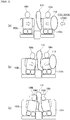
- FIG. 2 is view describing positional relationship between an occupant and cushion during an inflation collision.
- FIG. 2(a) to (c) illustrates conditions where vehicle seats and occupants seated therein are viewed from the front. Note that in FIG. 2(a) to (c) , only the cushion 110, which is observable in appearance, of the side airbag apparatus 100 is illustrated. Furthermore, for convenience of describing, a seat on a left side of the drawing of the two seats disposed side-by-side is referred to as a driver's seat 102b, and a seat on a right side of the drawing is referred to a front passenger's seat 102c.
- the cushion 110 cleaves the side surface 102a (refer to FIG. 1 ) on a far side of the front passenger's seat 102c, and the cushion 110 begins to inflate and expand.
- a cushion 210 of another side airbag apparatus expands on a near side of the front passenger's seat 102c of an occupant 106c such that the occupant 106c of the front passenger's seat 102c is pushed toward a center side in a vehicle width direction.
- an upper body (shoulder portion 104b and chest 104c) of the occupant of the front passenger's seat 102c moving toward the center side in the vehicle width direction by the cushion 110 on the near side is restrained by the cushion 110.
- an upper body (shoulder portion 104b and chest portion 104c) of the occupant 106b of the driver's seat 102b pushed to the center side in the vehicle width direction by the collision load is also restrained by the cushion 110.
- the head portions 104d of the occupants 106b/106c of the driver's seat 102b and front passenger's seat 102c are restrained by the cushion 110.
- the upper bodies of the occupant 106b of the driver's seat 102b and occupant 106c of the front passenger's seat 102 are restrained such that flow of the gas in the second chamber 134 to the third chamber 136 is promoted. Therefore, the restraining force of the head portion 104d by the cushion 110 (strictly, the third chamber 136) can be increased while absorbing energy near the shoulder portions of the occupants 106b/106c. Therefore, a high restraining force can be secured by the small inflator 150 even in the side airbag apparatus 100 that restrains both an upper body and head portion of an occupant.
- the side airbag apparatus 100 where the cushion 110 inflates and expands at a far side of the seat 102, in other words, a so-called far side airbag was exemplified, but the present invention is not limited thereto.
- the present invention can be applied in a side airbag apparatus where the cushion 110 inflates from a near side on a side surface on an opposite side of the seat 102.
- FIG. 2 a case where occupants are seated in both the driver's seat 102b and front passenger's seat 102c was exemplified and described, but the present invention is not limited thereto.
- the head portion and upper body of the occupant 106b in the driver's seat 102b can be suitably restrained by the side airbag apparatus of the present embodiment.
- the present invention relates to a side airbag apparatus that inflates and expands upward from a side surface of a vehicle seat.
Landscapes
- Engineering & Computer Science (AREA)
- Mechanical Engineering (AREA)
- Physics & Mathematics (AREA)
- Fluid Mechanics (AREA)
- Air Bags (AREA)
Abstract
Description
- The present invention relates to a side airbag apparatus that inflates and expands upward from a side surface of a vehicle seat.
- Airbags are standard equipment in almost all recent vehicles. A side airbag apparatus is a safety apparatus which is operated in case of an emergency such as a vehicle collision and, for example, includes a bag shaped cushion. There are various types of airbags depending on an installation point and application. One example thereof is a side airbag apparatus that inflates and expands right by a side of an occupant from a side surface of a seat in order to protect the occupant from a side-impact collision or subsequent rollover.
- For example, Patent Document 1 discloses a side airbag apparatus that is expanded between a side surface of a vehicle interior and an occupant. In the side airbag apparatus of Patent Document 1, an airbag is configured from a chest portion inflating chamber corresponding to a chest portion of an occupant and a head portion inflating chamber corresponding to a head portion of the occupant. As is also described in Patent Document 1, the side airbag apparatus that protects both the head portion and chest portion of the occupant has a large airbag volume. Therefore, time is required until complete inflation and expansion, and thus a large inflator having a long gas generating time must be adopted.
- Therefore, in Patent Document 1, expansion in a direction where inner surfaces of the airbag separate from each other is limited by a limiting part. As a result, the airbag volume when inflated is suppressed, and therefore, the size of the inflator can be reduced. Additionally, in Patent Document 1, expansion in a direction where inner surfaces of the airbag separate from each other is limited by making the limiting part to have a curved shape relative to the flow direction of the gas flowing from the head portion inflating chamber to the chest portion inflating chamber. Based thereon, it is said that damage of the limiting part due to gas pressure during inflation and expansion can be suppressed, and thus the reliability of the airbag can be improved.
- [Patent Document 1]
JP 10-175497 A - With the side airbag apparatus of Patent Document 1, a limiting part is provided between the chest portion inflating chamber and head portion inflating chamber, however, the chest portion inflating chamber and head portion inflating chamber are connected. Therefore, internal pressures of the chest portion inflating chamber and head portion inflating chamber when an airbag inflates and expands are essentially the same. Thereupon, restraining forces in a region restraining a head portion and region restraining a chest portion cannot be individually adjusted.
- Furthermore, the airbag apparatus is designed such that a maximum performance can be demonstrated when an occupant is in a normal occupant posture (regular seating posture) in the event of a collision. However, there is demand for the airbag apparatus to not provide an excessive impact even when the occupant is in an irregular seating posture). Therefore, an OOP (Out Of Position) test, which confirms that there is no hazardability in an irregular seating posture, in other words, OOP performance, is performed for airbag apparatuses. However, with the side airbag apparatus of Patent Document 1, no consideration is given for OOP performance, and there is room for further improvement.
- In view of the foregoing, an object of the present invention is to provide a side airbag apparatus which can protect a head portion and chest portion by an appropriate restraining force while favorably inflating and expanding even a cushion that protects a head portion and chest portion with a small inflator, and which can ensure high OOP performance.
- In order to solve the aforementioned problem, a representative configuration of a side airbag apparatus according to the present invention is a side airbag apparatus that inflates and expands upward from a side surface of a vehicle seat. The side airbag apparatus contains: a bag-like cushion; an inflator that supplies a gas to the cushion to inflate and expand; a first demarcating part that demarcates the cushion extending upward from a lower edge of the cushion when inflated and expanded into a first chamber on a vehicle rearward side and a second chamber on a vehicle forward side; and a second demarcating part that extends from a front edge to a rear edge of the cushion when inflated and expanded through an upper end of the first demarcating part to demarcate a third chamber on an upper side of the first chamber and second chamber. The first chamber is internally provided in the inflator and has a longitudinal shape in a vertical direction along a side surface of the seat. The side airbag apparatus further contains: a first inner vent disposed above the first demarcating part and that flows the gas supplied from the inflator from the first chamber to the second chamber; and a second inner vent disposed above the second demarcating part, which flows the gas flowing into the second chamber to the third chamber, and which is provided with a check valve structure that prevents reverse flow of the gas from the third chamber to the second chamber.
- In the aforementioned configuration, the cushion of the side airbag apparatus is demarcated into three chambers by the first demarcating part and second demarcating part. Of the three chambers, the second chamber restrains a shoulder portion and chest portion of an occupant, and the third chamber restrains a head portion of the occupant. Thereby, the entire upper body of the occupant can be sufficiently protected during a collision. In particular, the second chamber and third chamber are demarcated by the second demarcating part such that internal pressures in the chambers can be appropriately set. Therefore, the head portion and chest portion of the occupant can be protected by an appropriate restraining force.
- the first chamber has a longitudinal shape in a vertical direction along a side surface of the seat, Therefore, the first chamber contacts the side surface of the seat during inflation and expansion, however, the first chamber does not contact the occupant. Therefore, even if the occupant is in an irregular seating posture during inflation and expansion, an impact on the occupant can be drastically reduced, and high OOP performance can be secured.
- The gas supplied from the inflator during inflation and expansion flows from the first chamber to the second chamber through the first inner vent. The gas supplied to the second chamber flows to the third chamber through the second inner vent. At this time, the second inner vent has a check valve structure such that a reverse flow into the second chamber of the gas flowing into the third chamber is prevented. Therefore, the internal pressure in the third chamber can be kept high, and the restraining force of the head portion of the occupant can be increased.
- In this side airbag apparatus, a third inner vent is disposed above the second demarcating part, which flows the gas supplied from the inflator into the third chamber from the first chamber, and which is provided with a check valve structure that prevents reverse flow of the gas from the third chamber to the first chamber.
- According to the configuration, the gas can flow in from the first chamber to the third chamber through the third inner vent when the cushion is inflated and expanded. In other words, the gas is supplied to the third chamber without passing through the second chamber. Thereby, the third chamber can be rapidly inflated and expanded, and thus the head portion of the occupant can be quickly restrained. Furthermore, the check valve structure is also provided in the third inner vent, and therefore, a reverse flow of the gas from the third chamber into the first chamber is prevented. Therefore, the head portion and chest portion of the occupant can be protected by an appropriate restraining force.
- The cushion may be made to inflate and expand at a seat far side. Thereby, the aforementioned effect can be achieved in a side airbag apparatus that, for example, inflates and expands between a driver's seat and front passenger's seat, in other words, a so-called far side airbag apparatus.
- The second chamber is preferably positioned to protect a shoulder portion and chest portion of an occupant, the second demarcating part is preferably positioned at a height corresponding to a neck portion of the occupant, and the third chamber is preferably positioned to protect a head portion of the occupant. Of the three chambers, the second chamber restrains a shoulder portion and chest portion of an occupant, and the third chamber restrains a head portion of the occupant.
- In view of the foregoing, an object of the present invention is to provide a side airbag apparatus which can protect a head portion and chest portion by an appropriate restraining force while favorably inflating and expanding even a cushion that protects a head portion and chest portion with a small inflator, and which can ensure high OOP performance.
-
-
FIG. 1 is a view illustrating a side airbag apparatus according to the present embodiment. -
FIG. 2 is view describing positional relationship between an occupant and cushion during an inflation collision. - 100... Side airbag apparatus, 102... Seat, 102a... Side surface, 102b... Driver's seat, 102c... Front passenger's seat, 104... Occupant, 104a... Neck portion, 104b... Shoulder portion, 104c... Chest portion, 104d... Head portion, 106b... Occupant, 106c... Occupant, 110... Cushion, 110a... Lower edge, 110b... Front edge, 110c... Rear edge, 130a... First demarcating part, 130b... Second demarcating part, 132... First chamber, 134... Second chamber, 136... Third chamber, 142... First inner vent, 144... Second inner vent, 146... Third inner vent, 150... Inflator, 210... Cushion
- Preferred embodiments according to the present invention will hereinafter be described in detail with reference to the appended drawings. The dimensions, materials, other specific numerical values, etc. indicated in such embodiments are mere exemplifications for ease of understanding of the invention and do not limit the present invention unless otherwise noted. Note that in the present specification and drawings, elements having substantially identical functions and configurations are labeled with identical symbols to omit redundant descriptions along with the illustration of elements not directly related to the present invention.
-
FIG. 1 is a view illustrating aside airbag apparatus 100 according to the present embodiment.FIG. 2 is view describing positional relationship between an occupant and cushion during an inflation collision. Note that in order to facilitate understanding, aninflator 150 and aseat 102 of a vehicle (not entirely illustrated) are illustrated by imaginary lines. - As illustrated in
FIG. 1 , aside airbag apparatus 100 of the present embodiment is configured such that acushion 110 inflates and expands upward from aside surface 102a of aseat 102 of a vehicle. Thecushion 110 is a bag-like site that receives anoccupant 104 during an emergency such as when an impact occurs on the vehicle or the like. In the present embodiment, as illustrated inFIG. 2 , thecushion 110 inflates and expands in a flat shape on a vehicle center side of theseat 102, in other words, a so-called far side. - The
cushion 110 is formed to be bag-like by overlaying a plurality of base fabrics and the stitching or adhering. Thecushion 110 is stored by being wound or folded into a housing (omitted from the drawings) provided on theside surface 102a of theseat 102. Note that a top of thecushion 110 in a stored condition is covered by a seat cover or the like, and therefore cannot be visually recognized from the outside. Furthermore, when theside airbag apparatus 100 is operated, thecushion 110 cleaves a seat cover or the like and inflates and expands in front of theoccupant 104 to restrain the occupant from the side. Thereby, in the event of a side collision of the vehicle, the occupant moving in a center direction of the vehicle is received by thecushion 110. - An inflator 150 is installed along with the
cushion 110 on theside surface 102a of theseat 102. Theinflator 150 is a gas generating device, which receives an operation signal transmitted from a vehicle side when an impact occurs, and performs inflation and expansion by supplying a gas inside thecushion 110. The inflator 150 used in the present embodiment is a cylinder type, and is installed in thecushion 110 such that a longitudinal direction is included in a vertical direction. Theinflator 150 is fastened to the housing or the like of theside surface 102a of theseat 102 with a stud bolt (omitted from the drawings) integrated with a surface and that is exposed from the inside of thecushion 110 to the outside. - Currently
popular inflators 150 include: types where a gas generating agent is filled and combusted to generate a gas; types where compressed gas is filled to supply a gas without generating heat; hybrid types using both the combusted gas and compressed gas; and the like. Any type of the inflator 150 can be used. - As illustrated in
FIG. 1 , the cushion is demarcated into three chambers in theside airbag apparatus 100 of the present embodiment. Afirst demarcating part 130a extends upward from alower edge 110a of thecushion 110 when inflated and expanded. The inside of thecushion 110 is demarcated into afirst chamber 132 on a vehicle rearward side and asecond chamber 134 on a vehicle forward side by thefirst demarcating part 130a. - A
second demarcating part 130b extends through an upper end of thefirst demarcating part 130a from afront edge 110b to arear edge 110c of thecushion 110 when inflated and expanded. In the present invention, "occupant" is equivalent to a physique based on World SID established based on human body data of an adult male, for example, an international unified side collision dummy developed under ISO/TC22/SC12/WG5. The second demarcating part is positioned at a height corresponding to a neck portion of the occupant. The inside of thecushion 110 is demarcated into afirst chamber 132 on a vehicle rearward side and asecond chamber 136 on a vehicle forward side by thefirst demarcating part 130a. - The first chamber is internally provided in the inflator and has a longitudinal shape in a vertical direction along a side surface of the seat, The
second chamber 134 is disposed at a position for protecting ashoulder portion 104b andchest portion 104c of theoccupant 104. Thesecond demarcating part 130b is positioned at a height corresponding to theneck portion 104a of theoccupant 104, and therefore, thethird chamber 136 is disposed at a position for protecting thehead portion 104d of theoccupant 104. - Based on the configuration, of the three chambers demarcated by the
first demarcating part 130a and second demarcatingpart 130b, thesecond chamber 134 restrains theshoulder portion 104b andchest portion 104c of theoccupant 104, and thethird chamber 136 restrains thehead portion 104d of theoccupant 104. Thereby, the entire upper body of the occupant can be sufficiently protected during a collision. - Meanwhile, the
first chamber 132 along the side surface of theseat 102 contacts theside surface 102a of theseat 102, while hardly contacting theoccupant 104. In other words, thefirst chamber 132 functions as an LRD (low risk deployment: for OOP) chamber that does not provide excessive impact on theoccupant 104 at an initial stage during inflation and expansion. Therefore, even if the occupant is in an irregular seating posture during inflation and expansion, an impact on the occupant can be drastically reduced, and high OOP performance can be secured. - In particular, the second chamber and third chamber are demarcated by the second demarcating part such that internal pressures in the chambers can be appropriately set. Therefore, the head portion and chest portion of the occupant can be protected by an appropriate restraining force.
- Furthermore, the inside of the cushion is demarcated into three chambers by the
first demarcating part 130a and second demarcatingpart 130b, and an inner vent having a check valve structure described later is provided. Therefore, the internal volume of thecushion 110 is reduced as compared to the cushion is not demarcated. Thereby, alarge cushion 110 that protects thehead portion 104d,shoulder portion 104b, andchest portion 104c of theoccupant 104 can also be sufficiently inflated and expanded by thesmall inflator 150. Therefore, thesmall inflator 150 can be used in theside airbag apparatus 100, and thus the cost and size of the apparatus can be reduced. - Refer again to
FIG. 1 . As illustrated inFIG. 1 , a firstinner vent 142 is disposed above thefirst demarcating part 130a. Gas supplied from the inflator 150 flows to thesecond chamber 134 from thefirst chamber 132 through the firstinner vent 142. A secondinner vent 144 provided with a check valve structure is disposed above thesecond demarcating part 130b. Gas supplied from the inflator 150 flows to thesecond chamber 136 from thefirst chamber 132 through the firstinner vent 144. - Based on the configuration, the gas supplied from the inflator 150 flows through the
cushion 110 such that thefirst chamber 132,second chamber 134, andthird chamber 136 are inflated in this order. Thereby, the shoulder portion can be restrained at initial inflation and expansion, and the secondinner vent 144 is provided with a check valve structure such that the gas flowing into thethird chamber 136 can be prevented from reverse flowing into thesecond chamber 134. Therefore, the internal pressure in the third chamber can be kept high, and the restraining force of the head portion of the occupant can be increased. - A second
inner vent 146 provided with a check valve structure is disposed above thesecond demarcating part 130b. Gas supplied from the inflator 150 flows to thesecond chamber 136 from thefirst chamber 132 through the firstinner vent 146. In other words, the gas is supplied to the third chamber without passing through the second chamber. Thereby, the third chamber can be rapidly inflated and expanded, and thus the head portion of the occupant can be quickly restrained. - Furthermore, the first
inner vent 142 is provided such that an expanding force of thecushion 110 to the vehicle forward side can be increased. Furthermore, the firstinner vent 146 is provided such that an expanding force of thecushion 110 to the vehicle forward side can be increased. Therefore, based on the configuration, theside surface 102a of theseat 102 during inflation and expansion can be cleaved, and thecushion 110 can be efficiently inflated and expanded as a whole. - Furthermore, the check valve structure is also provided in the third inner vent, and therefore, a reverse flow of the gas from the third chamber into the first chamber is prevented. Therefore, the head portion and chest portion of the occupant can be protected by an appropriate restraining force. Note that in the present embodiment, a configuration is exemplified where the third
inner vent 146 is provided above thesecond demarcating part 130b, but is not limited thereto, and a configuration is possible where the thirdinner vent 146 is not provided. -
FIG. 2 is view describing positional relationship between an occupant and cushion during an inflation collision.FIG. 2(a) to (c) illustrates conditions where vehicle seats and occupants seated therein are viewed from the front. Note that inFIG. 2(a) to (c) , only thecushion 110, which is observable in appearance, of theside airbag apparatus 100 is illustrated. Furthermore, for convenience of describing, a seat on a left side of the drawing of the two seats disposed side-by-side is referred to as a driver'sseat 102b, and a seat on a right side of the drawing is referred to a front passenger'sseat 102c. - As illustrated in
FIG. 2(a) , when a collision load is applied on the front passenger'sseat 102c of the vehicle due to a side collision of the vehicle, thecushion 110 cleaves theside surface 102a (refer toFIG. 1 ) on a far side of the front passenger'sseat 102c, and thecushion 110 begins to inflate and expand. At this time, acushion 210 of another side airbag apparatus expands on a near side of the front passenger'sseat 102c of anoccupant 106c such that theoccupant 106c of the front passenger'sseat 102c is pushed toward a center side in a vehicle width direction. - As illustrated in
FIG. 2(b) , when thecushion 110 inflates and expands, an upper body (shoulder portion 104b andchest 104c) of the occupant of the front passenger'sseat 102c moving toward the center side in the vehicle width direction by thecushion 110 on the near side is restrained by thecushion 110. At this time, an upper body (shoulder portion 104b andchest portion 104c) of theoccupant 106b of the driver'sseat 102b pushed to the center side in the vehicle width direction by the collision load is also restrained by thecushion 110. - Thereafter, as illustrated in
FIG. 2(c) , thehead portions 104d of theoccupants 106b/106c of the driver'sseat 102b and front passenger'sseat 102c are restrained by thecushion 110. At this time, as illustrated inFIG. 2(b) , the upper bodies of theoccupant 106b of the driver'sseat 102b andoccupant 106c of the front passenger'sseat 102 are restrained such that flow of the gas in thesecond chamber 134 to thethird chamber 136 is promoted. Therefore, the restraining force of thehead portion 104d by the cushion 110 (strictly, the third chamber 136) can be increased while absorbing energy near the shoulder portions of theoccupants 106b/106c. Therefore, a high restraining force can be secured by thesmall inflator 150 even in theside airbag apparatus 100 that restrains both an upper body and head portion of an occupant. - Note that in the embodiment described above, the
side airbag apparatus 100 where thecushion 110 inflates and expands at a far side of theseat 102, in other words, a so-called far side airbag was exemplified, but the present invention is not limited thereto. The present invention can be applied in a side airbag apparatus where thecushion 110 inflates from a near side on a side surface on an opposite side of theseat 102. - Furthermore, in
FIG. 2 , a case where occupants are seated in both the driver'sseat 102b and front passenger'sseat 102c was exemplified and described, but the present invention is not limited thereto. For example, if an occupant is only seated in the driver'sseat 102b, the head portion and upper body of theoccupant 106b in the driver'sseat 102b can be suitably restrained by the side airbag apparatus of the present embodiment. - A preferred example of the present invention was described above while referring the accompanying drawings. However, the embodiment described above is a preferred example of the present invention, and other embodiments may be implemented or performed by various methods. In particular, unless described otherwise in the specification of the present application, the invention is not restricted to a shape, a size, configurational disposition, and the like of parts illustrated in detail in the accompanying drawings. Furthermore, expressions and terms used in the specification of the present application are used for providing the description, and thus the invention is not limited thereto, unless particularly described otherwise.
- Therefore, it is obvious that a person with ordinary skill in the art can conceive various changed examples or modified examples within a scope described in the scope of the claims, which is understood to naturally belong to the technical scope of the present invention.
- The present invention relates to a side airbag apparatus that inflates and expands upward from a side surface of a vehicle seat.
Claims (4)
- A side airbag apparatus that inflates and expands upward from a side surface of a vehicle seat,
the side airbag apparatus comprising:a bag-shaped cushion;an inflator that supplies a gas to the cushion to inflate and expand;a first demarcating part that demarcates the cushion extending upward from a lower edge of the cushion when inflated and expanded into a first chamber on a vehicle rearward side and a second chamber on a vehicle forward side; anda second demarcating part that extends from a front edge to a rear edge of the cushion when inflated and expanded through an upper end of the first demarcating part to demarcate a third chamber on an upper side of the first chamber and second chamber;the first chamber being internally provided in the inflator and having a longitudinal shape in a vertical direction along a side surface of the seat; and
the side airbag apparatus further comprising:a first inner vent disposed above the first demarcating part and that flows the gas supplied from the inflator from the first chamber to the second chamber; anda second inner vent disposed above the second demarcating part, which flows the gas flowing into the second chamber to the third chamber, and which is provided with a check valve structure that prevents reverse flow of the gas from the third chamber to the second chamber. - The airbag apparatus according to claim 1, further comprising a second inner vent disposed above the second demarcating part, which flows the gas flowing into the second chamber to the third chamber, and which is provided with a check valve structure that prevents reverse flow of the gas from the third chamber to the second chamber.
- The airbag apparatus according to claim 1 or 2, wherein the cushion inflates and expands at a seat far side.
- The side airbag apparatus according to any one of claims 1 through 3, wherein:the second chamber is positioned to protect a shoulder portion and chest portion of an occupant,the second demarcating part is positioned at a height corresponding to a neck portion of the occupant, andthe third chamber is positioned to protect a head portion of the occupant.
Applications Claiming Priority (2)
| Application Number | Priority Date | Filing Date | Title |
|---|---|---|---|
| JP2017100010 | 2017-05-19 | ||
| PCT/JP2018/015829 WO2018211894A1 (en) | 2017-05-19 | 2018-04-17 | Side air bag device |
Publications (3)
| Publication Number | Publication Date |
|---|---|
| EP3626546A1 true EP3626546A1 (en) | 2020-03-25 |
| EP3626546A4 EP3626546A4 (en) | 2020-11-18 |
| EP3626546B1 EP3626546B1 (en) | 2021-10-13 |
Family
ID=64273548
Family Applications (1)
| Application Number | Title | Priority Date | Filing Date |
|---|---|---|---|
| EP18802631.4A Active EP3626546B1 (en) | 2017-05-19 | 2018-04-17 | Side air bag device |
Country Status (6)
| Country | Link |
|---|---|
| US (1) | US11104288B2 (en) |
| EP (1) | EP3626546B1 (en) |
| JP (1) | JP6768943B2 (en) |
| KR (1) | KR102352139B1 (en) |
| CN (1) | CN110546043A (en) |
| WO (1) | WO2018211894A1 (en) |
Families Citing this family (6)
| Publication number | Priority date | Publication date | Assignee | Title |
|---|---|---|---|---|
| JP6789606B2 (en) * | 2017-08-01 | 2020-11-25 | オートリブ ディベロップメント エービー | Crew protection device |
| DE102019107364A1 (en) * | 2019-03-22 | 2020-09-24 | Audi Ag | Side gas bag module, vehicle seat and vehicle |
| US20230034054A1 (en) * | 2020-01-23 | 2023-02-02 | Autoliv Development Ab | Airbag device |
| KR20210158485A (en) * | 2020-06-24 | 2021-12-31 | 현대모비스 주식회사 | Side air bag apparatus for vehicle |
| US11858446B2 (en) * | 2021-04-22 | 2024-01-02 | Ford Global Technologies, Llc | Seatback-mounted airbag |
| WO2023200032A1 (en) * | 2022-04-15 | 2023-10-19 | 아우토리브 디벨롭먼트 아베 | Side airbag device for vehicle |
Family Cites Families (28)
| Publication number | Priority date | Publication date | Assignee | Title |
|---|---|---|---|---|
| KR0175497B1 (en) | 1996-07-26 | 1999-02-01 | 담철곤 | Process for preparing xylitol by oxidation reduction potential control |
| JPH10100827A (en) | 1996-09-26 | 1998-04-21 | Mitsubishi Motors Corp | Air bag device |
| JP3760537B2 (en) | 1996-12-20 | 2006-03-29 | マツダ株式会社 | Side airbag device |
| US6270113B1 (en) * | 1998-10-06 | 2001-08-07 | Breed Automotive Technology, Inc. | Side air bag system |
| JP3900765B2 (en) * | 1999-12-08 | 2007-04-04 | タカタ株式会社 | Airbag device |
| JP4285633B2 (en) * | 2003-01-31 | 2009-06-24 | 芦森工業株式会社 | Airbag device |
| DE102005028702A1 (en) * | 2004-06-28 | 2006-03-16 | Mazda Motor Corp. | Airbag device |
| JP4453966B2 (en) | 2004-06-28 | 2010-04-21 | マツダ株式会社 | Airbag device |
| JP4846595B2 (en) * | 2004-11-04 | 2011-12-28 | オートリブ ディベロップメント エービー | Side airbag device for vehicle |
| EP1829755A4 (en) * | 2004-11-05 | 2009-04-01 | Autoliv Dev | Side air bag device and side air bag system |
| US7338070B2 (en) * | 2005-03-14 | 2008-03-04 | Ford Global Technologies, Llc | Multi-chambered air bag for a motor vehicle |
| DE202006010362U1 (en) * | 2006-06-29 | 2006-09-14 | Takata-Petri Ag | Side airbag, comprising functional band for successive inflating and retaining position of chambers |
| US7770921B2 (en) * | 2007-05-25 | 2010-08-10 | Autoliv Development Ab | Airbag for protection of a vehicle occupant |
| US20090200774A1 (en) * | 2008-02-13 | 2009-08-13 | Cis Tech, Llc | Low risk deployment side airbag system |
| KR101619390B1 (en) * | 2009-06-10 | 2016-05-10 | 아우토리브 디벨롭먼트 아베 | Air bag system |
| US8480124B2 (en) * | 2011-01-18 | 2013-07-09 | Autoliv Asp, Inc. | Seat bolster chamber |
| JP5918621B2 (en) | 2012-05-09 | 2016-05-18 | 芦森工業株式会社 | Side airbag device |
| US9254811B2 (en) * | 2012-06-06 | 2016-02-09 | Toyota Jidosha Kabushiki Kaisha | Vehicle side-airbag device |
| KR101406409B1 (en) * | 2012-11-16 | 2014-06-13 | 현대자동차주식회사 | Side airbag |
| WO2014098027A1 (en) * | 2012-12-20 | 2014-06-26 | オートリブ ディベロップメント エービー | Airbag device |
| JP5696748B2 (en) * | 2013-07-31 | 2015-04-08 | トヨタ自動車株式会社 | Side airbag device for vehicle and vehicle seat |
| US9598043B2 (en) * | 2013-08-06 | 2017-03-21 | Autoliv Development Ab | Side airbag device for vehicles |
| JP6222008B2 (en) * | 2013-12-26 | 2017-11-01 | 豊田合成株式会社 | Side airbag device |
| US9580039B2 (en) | 2014-04-22 | 2017-02-28 | Autoliv Asp, Inc. | Multi-chamber airbag with unidirectional vent |
| JP6115542B2 (en) | 2014-10-10 | 2017-04-19 | トヨタ自動車株式会社 | Side airbag device for vehicle |
| JP6454404B2 (en) * | 2015-03-23 | 2019-01-16 | オートリブ ディベロップメント エービー | Airbag device |
| JP6354044B2 (en) * | 2015-04-27 | 2018-07-11 | オートリブ ディベロップメント エービー | Side airbag device |
| US10124759B2 (en) | 2016-09-20 | 2018-11-13 | Autoliv Asp, Inc. | Aspirating airbag assemblies |
-
2018
- 2018-04-17 CN CN201880027894.XA patent/CN110546043A/en active Pending
- 2018-04-17 US US16/615,008 patent/US11104288B2/en active Active
- 2018-04-17 EP EP18802631.4A patent/EP3626546B1/en active Active
- 2018-04-17 WO PCT/JP2018/015829 patent/WO2018211894A1/en unknown
- 2018-04-17 KR KR1020197035843A patent/KR102352139B1/en active IP Right Grant
- 2018-04-17 JP JP2019519135A patent/JP6768943B2/en active Active
Also Published As
| Publication number | Publication date |
|---|---|
| JPWO2018211894A1 (en) | 2020-01-16 |
| KR20200003413A (en) | 2020-01-09 |
| US20200180540A1 (en) | 2020-06-11 |
| EP3626546A4 (en) | 2020-11-18 |
| CN110546043A (en) | 2019-12-06 |
| US11104288B2 (en) | 2021-08-31 |
| JP6768943B2 (en) | 2020-10-14 |
| KR102352139B1 (en) | 2022-01-18 |
| EP3626546B1 (en) | 2021-10-13 |
| WO2018211894A1 (en) | 2018-11-22 |
Similar Documents
| Publication | Publication Date | Title |
|---|---|---|
| EP3626546B1 (en) | Side air bag device | |
| JP6504296B2 (en) | Occupant protection device | |
| US10093269B2 (en) | Passenger protecting device for vehicle | |
| US7350811B2 (en) | Side airbag apparatus | |
| US10166945B2 (en) | Far side airbag device for vehicle | |
| EP3173295B1 (en) | Side air-bag device | |
| US9545893B2 (en) | Far side airbag device for vehicle | |
| KR20100120400A (en) | Airbag module | |
| JP2003285713A (en) | Side air bag device | |
| JP6475150B2 (en) | Crew protection device | |
| KR20200029022A (en) | Passenger protection | |
| US20120292897A1 (en) | Dual depth airbag | |
| JP2005231504A (en) | Occupant crash protection device | |
| JP2008037276A (en) | Side airbag device | |
| US11433843B2 (en) | Occupant restraining device | |
| WO2020017280A1 (en) | Passenger restraint device | |
| JP5549577B2 (en) | Side airbag device for rear seats | |
| JP2019172029A (en) | Air bag device for vehicle | |
| CN111886161B (en) | Airbag device | |
| CN110871765B (en) | Airbag device | |
| WO2023282017A1 (en) | Airbag device | |
| WO2024053518A1 (en) | Occupant protection device |
Legal Events
| Date | Code | Title | Description |
|---|---|---|---|
| STAA | Information on the status of an ep patent application or granted ep patent |
Free format text: STATUS: THE INTERNATIONAL PUBLICATION HAS BEEN MADE |
|
| PUAI | Public reference made under article 153(3) epc to a published international application that has entered the european phase |
Free format text: ORIGINAL CODE: 0009012 |
|
| STAA | Information on the status of an ep patent application or granted ep patent |
Free format text: STATUS: REQUEST FOR EXAMINATION WAS MADE |
|
| 17P | Request for examination filed |
Effective date: 20191216 |
|
| AK | Designated contracting states |
Kind code of ref document: A1 Designated state(s): AL AT BE BG CH CY CZ DE DK EE ES FI FR GB GR HR HU IE IS IT LI LT LU LV MC MK MT NL NO PL PT RO RS SE SI SK SM TR |
|
| AX | Request for extension of the european patent |
Extension state: BA ME |
|
| DAV | Request for validation of the european patent (deleted) | ||
| DAX | Request for extension of the european patent (deleted) | ||
| A4 | Supplementary search report drawn up and despatched |
Effective date: 20201019 |
|
| RIC1 | Information provided on ipc code assigned before grant |
Ipc: B60R 21/26 20110101ALI20201013BHEP Ipc: B60R 21/233 20060101ALI20201013BHEP Ipc: B60R 21/207 20060101AFI20201013BHEP |
|
| GRAP | Despatch of communication of intention to grant a patent |
Free format text: ORIGINAL CODE: EPIDOSNIGR1 |
|
| STAA | Information on the status of an ep patent application or granted ep patent |
Free format text: STATUS: GRANT OF PATENT IS INTENDED |
|
| INTG | Intention to grant announced |
Effective date: 20210604 |
|
| RIN1 | Information on inventor provided before grant (corrected) |
Inventor name: FUMA, MAKOTO Inventor name: KOBAYASHI, YUTO |
|
| GRAS | Grant fee paid |
Free format text: ORIGINAL CODE: EPIDOSNIGR3 |
|
| GRAA | (expected) grant |
Free format text: ORIGINAL CODE: 0009210 |
|
| STAA | Information on the status of an ep patent application or granted ep patent |
Free format text: STATUS: THE PATENT HAS BEEN GRANTED |
|
| AK | Designated contracting states |
Kind code of ref document: B1 Designated state(s): AL AT BE BG CH CY CZ DE DK EE ES FI FR GB GR HR HU IE IS IT LI LT LU LV MC MK MT NL NO PL PT RO RS SE SI SK SM TR |
|
| REG | Reference to a national code |
Ref country code: GB Ref legal event code: FG4D |
|
| REG | Reference to a national code |
Ref country code: CH Ref legal event code: EP |
|
| REG | Reference to a national code |
Ref country code: DE Ref legal event code: R096 Ref document number: 602018025092 Country of ref document: DE |
|
| REG | Reference to a national code |
Ref country code: IE Ref legal event code: FG4D |
|
| REG | Reference to a national code |
Ref country code: AT Ref legal event code: REF Ref document number: 1437972 Country of ref document: AT Kind code of ref document: T Effective date: 20211115 |
|
| REG | Reference to a national code |
Ref country code: LT Ref legal event code: MG9D |
|
| REG | Reference to a national code |
Ref country code: NL Ref legal event code: MP Effective date: 20211013 |
|
| REG | Reference to a national code |
Ref country code: AT Ref legal event code: MK05 Ref document number: 1437972 Country of ref document: AT Kind code of ref document: T Effective date: 20211013 |
|
| PG25 | Lapsed in a contracting state [announced via postgrant information from national office to epo] |
Ref country code: RS Free format text: LAPSE BECAUSE OF FAILURE TO SUBMIT A TRANSLATION OF THE DESCRIPTION OR TO PAY THE FEE WITHIN THE PRESCRIBED TIME-LIMIT Effective date: 20211013 Ref country code: LT Free format text: LAPSE BECAUSE OF FAILURE TO SUBMIT A TRANSLATION OF THE DESCRIPTION OR TO PAY THE FEE WITHIN THE PRESCRIBED TIME-LIMIT Effective date: 20211013 Ref country code: FI Free format text: LAPSE BECAUSE OF FAILURE TO SUBMIT A TRANSLATION OF THE DESCRIPTION OR TO PAY THE FEE WITHIN THE PRESCRIBED TIME-LIMIT Effective date: 20211013 Ref country code: BG Free format text: LAPSE BECAUSE OF FAILURE TO SUBMIT A TRANSLATION OF THE DESCRIPTION OR TO PAY THE FEE WITHIN THE PRESCRIBED TIME-LIMIT Effective date: 20220113 Ref country code: AT Free format text: LAPSE BECAUSE OF FAILURE TO SUBMIT A TRANSLATION OF THE DESCRIPTION OR TO PAY THE FEE WITHIN THE PRESCRIBED TIME-LIMIT Effective date: 20211013 |
|
| PG25 | Lapsed in a contracting state [announced via postgrant information from national office to epo] |
Ref country code: IS Free format text: LAPSE BECAUSE OF FAILURE TO SUBMIT A TRANSLATION OF THE DESCRIPTION OR TO PAY THE FEE WITHIN THE PRESCRIBED TIME-LIMIT Effective date: 20220213 Ref country code: SE Free format text: LAPSE BECAUSE OF FAILURE TO SUBMIT A TRANSLATION OF THE DESCRIPTION OR TO PAY THE FEE WITHIN THE PRESCRIBED TIME-LIMIT Effective date: 20211013 Ref country code: PT Free format text: LAPSE BECAUSE OF FAILURE TO SUBMIT A TRANSLATION OF THE DESCRIPTION OR TO PAY THE FEE WITHIN THE PRESCRIBED TIME-LIMIT Effective date: 20220214 Ref country code: PL Free format text: LAPSE BECAUSE OF FAILURE TO SUBMIT A TRANSLATION OF THE DESCRIPTION OR TO PAY THE FEE WITHIN THE PRESCRIBED TIME-LIMIT Effective date: 20211013 Ref country code: NO Free format text: LAPSE BECAUSE OF FAILURE TO SUBMIT A TRANSLATION OF THE DESCRIPTION OR TO PAY THE FEE WITHIN THE PRESCRIBED TIME-LIMIT Effective date: 20220113 Ref country code: NL Free format text: LAPSE BECAUSE OF FAILURE TO SUBMIT A TRANSLATION OF THE DESCRIPTION OR TO PAY THE FEE WITHIN THE PRESCRIBED TIME-LIMIT Effective date: 20211013 Ref country code: LV Free format text: LAPSE BECAUSE OF FAILURE TO SUBMIT A TRANSLATION OF THE DESCRIPTION OR TO PAY THE FEE WITHIN THE PRESCRIBED TIME-LIMIT Effective date: 20211013 Ref country code: HR Free format text: LAPSE BECAUSE OF FAILURE TO SUBMIT A TRANSLATION OF THE DESCRIPTION OR TO PAY THE FEE WITHIN THE PRESCRIBED TIME-LIMIT Effective date: 20211013 Ref country code: GR Free format text: LAPSE BECAUSE OF FAILURE TO SUBMIT A TRANSLATION OF THE DESCRIPTION OR TO PAY THE FEE WITHIN THE PRESCRIBED TIME-LIMIT Effective date: 20220114 Ref country code: ES Free format text: LAPSE BECAUSE OF FAILURE TO SUBMIT A TRANSLATION OF THE DESCRIPTION OR TO PAY THE FEE WITHIN THE PRESCRIBED TIME-LIMIT Effective date: 20211013 |
|
| REG | Reference to a national code |
Ref country code: DE Ref legal event code: R097 Ref document number: 602018025092 Country of ref document: DE |
|
| PG25 | Lapsed in a contracting state [announced via postgrant information from national office to epo] |
Ref country code: SM Free format text: LAPSE BECAUSE OF FAILURE TO SUBMIT A TRANSLATION OF THE DESCRIPTION OR TO PAY THE FEE WITHIN THE PRESCRIBED TIME-LIMIT Effective date: 20211013 Ref country code: SK Free format text: LAPSE BECAUSE OF FAILURE TO SUBMIT A TRANSLATION OF THE DESCRIPTION OR TO PAY THE FEE WITHIN THE PRESCRIBED TIME-LIMIT Effective date: 20211013 Ref country code: RO Free format text: LAPSE BECAUSE OF FAILURE TO SUBMIT A TRANSLATION OF THE DESCRIPTION OR TO PAY THE FEE WITHIN THE PRESCRIBED TIME-LIMIT Effective date: 20211013 Ref country code: EE Free format text: LAPSE BECAUSE OF FAILURE TO SUBMIT A TRANSLATION OF THE DESCRIPTION OR TO PAY THE FEE WITHIN THE PRESCRIBED TIME-LIMIT Effective date: 20211013 Ref country code: DK Free format text: LAPSE BECAUSE OF FAILURE TO SUBMIT A TRANSLATION OF THE DESCRIPTION OR TO PAY THE FEE WITHIN THE PRESCRIBED TIME-LIMIT Effective date: 20211013 Ref country code: CZ Free format text: LAPSE BECAUSE OF FAILURE TO SUBMIT A TRANSLATION OF THE DESCRIPTION OR TO PAY THE FEE WITHIN THE PRESCRIBED TIME-LIMIT Effective date: 20211013 |
|
| PLBE | No opposition filed within time limit |
Free format text: ORIGINAL CODE: 0009261 |
|
| STAA | Information on the status of an ep patent application or granted ep patent |
Free format text: STATUS: NO OPPOSITION FILED WITHIN TIME LIMIT |
|
| 26N | No opposition filed |
Effective date: 20220714 |
|
| PG25 | Lapsed in a contracting state [announced via postgrant information from national office to epo] |
Ref country code: AL Free format text: LAPSE BECAUSE OF FAILURE TO SUBMIT A TRANSLATION OF THE DESCRIPTION OR TO PAY THE FEE WITHIN THE PRESCRIBED TIME-LIMIT Effective date: 20211013 |
|
| PG25 | Lapsed in a contracting state [announced via postgrant information from national office to epo] |
Ref country code: SI Free format text: LAPSE BECAUSE OF FAILURE TO SUBMIT A TRANSLATION OF THE DESCRIPTION OR TO PAY THE FEE WITHIN THE PRESCRIBED TIME-LIMIT Effective date: 20211013 |
|
| REG | Reference to a national code |
Ref country code: CH Ref legal event code: PL |
|
| REG | Reference to a national code |
Ref country code: BE Ref legal event code: MM Effective date: 20220430 |
|
| PG25 | Lapsed in a contracting state [announced via postgrant information from national office to epo] |
Ref country code: MC Free format text: LAPSE BECAUSE OF FAILURE TO SUBMIT A TRANSLATION OF THE DESCRIPTION OR TO PAY THE FEE WITHIN THE PRESCRIBED TIME-LIMIT Effective date: 20211013 Ref country code: LU Free format text: LAPSE BECAUSE OF NON-PAYMENT OF DUE FEES Effective date: 20220417 Ref country code: CH Free format text: LAPSE BECAUSE OF NON-PAYMENT OF DUE FEES Effective date: 20220430 Ref country code: LI Free format text: LAPSE BECAUSE OF NON-PAYMENT OF DUE FEES Effective date: 20220430 |
|
| PG25 | Lapsed in a contracting state [announced via postgrant information from national office to epo] |
Ref country code: BE Free format text: LAPSE BECAUSE OF NON-PAYMENT OF DUE FEES Effective date: 20220430 |
|
| PG25 | Lapsed in a contracting state [announced via postgrant information from national office to epo] |
Ref country code: IE Free format text: LAPSE BECAUSE OF NON-PAYMENT OF DUE FEES Effective date: 20220417 |
|
| PG25 | Lapsed in a contracting state [announced via postgrant information from national office to epo] |
Ref country code: IT Free format text: LAPSE BECAUSE OF FAILURE TO SUBMIT A TRANSLATION OF THE DESCRIPTION OR TO PAY THE FEE WITHIN THE PRESCRIBED TIME-LIMIT Effective date: 20211013 |
|
| P01 | Opt-out of the competence of the unified patent court (upc) registered |
Effective date: 20230507 |
|
| PG25 | Lapsed in a contracting state [announced via postgrant information from national office to epo] |
Ref country code: MK Free format text: LAPSE BECAUSE OF FAILURE TO SUBMIT A TRANSLATION OF THE DESCRIPTION OR TO PAY THE FEE WITHIN THE PRESCRIBED TIME-LIMIT Effective date: 20211013 Ref country code: CY Free format text: LAPSE BECAUSE OF FAILURE TO SUBMIT A TRANSLATION OF THE DESCRIPTION OR TO PAY THE FEE WITHIN THE PRESCRIBED TIME-LIMIT Effective date: 20211013 |
|
| PG25 | Lapsed in a contracting state [announced via postgrant information from national office to epo] |
Ref country code: HU Free format text: LAPSE BECAUSE OF FAILURE TO SUBMIT A TRANSLATION OF THE DESCRIPTION OR TO PAY THE FEE WITHIN THE PRESCRIBED TIME-LIMIT; INVALID AB INITIO Effective date: 20180417 |
|
| PGFP | Annual fee paid to national office [announced via postgrant information from national office to epo] |
Ref country code: GB Payment date: 20240423 Year of fee payment: 7 |
|
| PGFP | Annual fee paid to national office [announced via postgrant information from national office to epo] |
Ref country code: DE Payment date: 20240429 Year of fee payment: 7 |
|
| PGFP | Annual fee paid to national office [announced via postgrant information from national office to epo] |
Ref country code: FR Payment date: 20240430 Year of fee payment: 7 |