EP3626525B1 - Fahrzeugsitz mit bedienungseinrichtung - Google Patents
Fahrzeugsitz mit bedienungseinrichtung Download PDFInfo
- Publication number
- EP3626525B1 EP3626525B1 EP19196573.0A EP19196573A EP3626525B1 EP 3626525 B1 EP3626525 B1 EP 3626525B1 EP 19196573 A EP19196573 A EP 19196573A EP 3626525 B1 EP3626525 B1 EP 3626525B1
- Authority
- EP
- European Patent Office
- Prior art keywords
- armrest
- axis
- along
- vehicle seat
- lever element
- Prior art date
- Legal status (The legal status is an assumption and is not a legal conclusion. Google has not performed a legal analysis and makes no representation as to the accuracy of the status listed.)
- Active
Links
Images


Classifications
-
- B—PERFORMING OPERATIONS; TRANSPORTING
- B60—VEHICLES IN GENERAL
- B60N—SEATS SPECIALLY ADAPTED FOR VEHICLES; VEHICLE PASSENGER ACCOMMODATION NOT OTHERWISE PROVIDED FOR
- B60N2/00—Seats specially adapted for vehicles; Arrangement or mounting of seats in vehicles
- B60N2/75—Arm-rests
- B60N2/79—Adaptations for additional use of the arm-rests
- B60N2/797—Adaptations for additional use of the arm-rests for use as electrical control means, e.g. switches
-
- B—PERFORMING OPERATIONS; TRANSPORTING
- B60—VEHICLES IN GENERAL
- B60N—SEATS SPECIALLY ADAPTED FOR VEHICLES; VEHICLE PASSENGER ACCOMMODATION NOT OTHERWISE PROVIDED FOR
- B60N2/00—Seats specially adapted for vehicles; Arrangement or mounting of seats in vehicles
- B60N2/90—Details or parts not otherwise provided for
- B60N2/919—Positioning and locking mechanisms
- B60N2/929—Positioning and locking mechanisms linear
Definitions
- the invention relates to a vehicle seat with an operating device for operating vehicle functions, the operating device being arranged by means of a guide device on an armrest of the vehicle seat and firmly connected to it and comprising an operating element arranged on a lever element, according to the preamble of claim 1.
- Vehicle seats particularly in the commercial vehicle sector, often have joysticks and various operating elements arranged in an area of the right armrest. This is especially true for tractors and the like.
- operating elements are usually not arranged directly on the vehicle seat or armrest, but in the dashboard area, as is known from the automotive sector.
- the object of the invention is accordingly to provide an operating device which enables various vehicle functions to be operated and which is arranged to save space and to be easily accessible to the operator at the same time.
- a vehicle seat in particular a truck seat
- an operating device for operating vehicle functions the operating device being arranged by means of a guide device on an armrest of the vehicle seat and firmly connected to it and comprising an operating element arranged on a lever element.
- the lever element is movable by means of the guide device along a longitudinal axis of the armrest relative to the armrest, the lever element being moved forward from a retracted state to an extended state by a first translational movement along the longitudinal axis and from the retracted state to the rear by a second translational movement along the longitudinal axis extended state can be converted into the retracted state.
- an operating device which is arranged on the armrest and which can be pulled in and out, provides a non-disruptive operating device which is at hand at all times to the person using this vehicle seat, i.e. can be operated without the person using the Take your arm off the armrest.
- the vehicle seat is preferably a commercial vehicle seat and particularly preferably a truck seat.
- the vehicle seat is preferably arranged within a vehicle cabin, preferably a utility vehicle cabin and particularly preferably a truck cabin.
- the vehicle seat or the armrest extend along a height axis Z, a width axis Y and a length axis X, two directions being assigned to the respective axes.
- the height axis Z thus includes the directions Z1 (upwards) and Z2 (downwards).
- the latitude axis Y includes the directions Y1 (to the right) and Y2 (to the left).
- the length axis X comprises the directions X1 (to the front) and X2 (to the rear).
- the expression "essentially” used should be interpreted in such a way that even slight tolerance deviations are also claimed.
- the deviation can thus be an angle of preferably less than 10 °, more preferably less than 7.5 °, even more preferably be less than 5 °. This also applies to the terms "essentially” used below.
- a vehicle function is understood to mean those functions which relate to devices in and / or on the vehicle or devices connected to the vehicle for signaling purposes.
- This can be, for example, a multimedia system, an air conditioning system, a telephone or mobile phone / smartphone connected to the vehicle, vehicle seat functions, in particular a seat height adjustment, as well as a vertical seat cushioning, a seat length adjustment, a backrest inclination, a seat inclination, a seat air conditioning device, a seat contour adjustment device and / or a massage device, or the like.
- vehicle seat functions in particular a seat height adjustment, as well as a vertical seat cushioning, a seat length adjustment, a backrest inclination, a seat inclination, a seat air conditioning device, a seat contour adjustment device and / or a massage device, or the like.
- This list is only intended to be exemplary and not to be understood as being conclusive.
- the retracted state is a storage state or a non-use state and the extended state is a state of use or a state of use in which the corresponding vehicle functions can be set by the operating device or control element.
- a fixed connection is a permanent connection, such as a welded connection, an adhesive connection, a plug connection, a rivet connection, a screw connection, a bolt connection or the like.
- the vehicle functions can preferably be operated by means of the operating element of the operating device. Furthermore, the operating element can also be moved in an analogous manner by moving the lever element connected to it.
- the operating device is signal-connected to the vehicle, the vehicle seat or the vehicle electronics in order to ensure that the corresponding vehicle functions are operated.
- the operating device is arranged along the longitudinal axis at the front of the armrest.
- An arm of an operator of the operating device or of the vehicle seat is preferably arranged on the armrest in such a way that one hand is located along the longitudinal axis at the front of the armrest and an elbow joint is located along the longitudinal axis at the rear of the armrest.
- the preferred arrangement of the operating device means that it is particularly easy for an operator to reach.
- the operating element is designed like a disk.
- the operating element according to claim 1 extends essentially in the length axis and in a width axis of the armrest, the operating element being arranged on an upper surface of the lever element in relation to a height axis of the armrest. Due to the flat, disk-like configuration of the operating element, the required installation space is reduced along the height axis.
- the operating element is cylindrical, with an axial direction of the cylinder being arranged parallel to the height axis.
- the arrangement of the operating element on the lever element makes it particularly easy for an operator to operate.
- An upper surface of the operating element which is directed upwards along the height axis, is designed to be touch-sensitive and thus enables various characters to be entered and various functions to be actuated by means of a finger on the operator or the driver. Furthermore, the upper surface of the operating element has a display and in particular a touchscreen, so that direct operation is guaranteed.
- the operating device in the front area of the dashboard displays the vehicle functions that have been carried out and / or operated.
- the settings made are easier to see for the driver and he does not have to direct his gaze to the operating device.
- the operating element is rotatably connected to the lever element about a first axis of rotation and the first axis of rotation is arranged essentially perpendicular to the longitudinal axis.
- various functions can be selected and / or one Operation of a navigation system, such as entering an address using individual letters, can be carried out.
- the lever element and the operating element are arranged essentially inside the armrest in the retracted state and at least partially outside the armrest in the extended state, the operating element being arranged in the extended state along the longitudinal axis in front of the armrest. In this way, the lever element and the operating element cannot hinder the driver in a retracted state when not in use and the operating element can be easily operated in the extended state without the driver having to change his position.
- the guide device has an elongated guide element for performing the first and second translational movement of the lever element, a first axial end of the guide element being firmly connected to the armrest and a second axial end of the guide element being firmly connected to the lever element.
- the lever element is thus arranged to be guided by the guide device or the guide element.
- the first translational movement is preferably limited to the front in the longitudinal direction by the guide element.
- the guide element is also preferably acted upon by force, preferably spring-loaded and in particular designed as a spring pressure rod, the spring force acting along the longitudinal axis and the first translational movement being able to be carried out automatically as a result.
- the guide element is arranged within the armrest to extend along the longitudinal axis of the armrest.
- the guide element is thus arranged in a space-saving and secure manner within the armrest.
- the operating device has a locking device comprising a locking means and a holding means, the locking means being fixedly connected to the lever element and the holding means being fixedly connected to the armrest.
- the locking device By means of the locking device, the mobility of the lever element can be restricted if necessary, as a result of which an undesired transition from the retracted state to the extended state can be prevented.
- the locking device is preferably designed in such a way that locking can be carried out reversibly.
- the locking means is elongated and extends backwards along the longitudinal axis, the holding means being arranged on a lower surface of the armrest in relation to the height axis. Due to the claimed arrangement, the locking device does not affect a driver.
- the first translational movement can be locked by the locking means engaging in the holding means.
- the lever element can be locked within the armrest and the first translational movement is prevented.
- the operating device can thus be locked in the space-saving retracted state and can only be extended when required.
- lever element is pivotably connected to the armrest about an axis, this axis running parallel to the height axis.
- a rotational movement of the lever element in the extended state relative to the armrest in a plane in the latitudinal axis and the longitudinal axis to the left and right would thus be possible. In this way, the operator or the driver could reach the operating device better and adapt it to his needs.
- the lever element prefferably has a further axis which is arranged parallel to the width axis and perpendicular to the length axis. This axis is arranged outside the armrest in the extended state and enables a rotational movement of the lever element in the plane of the length axis and the height axis up and down. As a result, the operator or the driver can reach the operating device more easily and adapt it to his arm length or his sitting position.
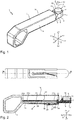
- the Figure 1 shows the operating device 2, which is arranged on the armrest 3, comprising a lever element 4 and an operating element 5, in an extended state.
- the vehicle seat 1 and the armrest 3 extend along a height axis Z, a width axis Y and a length axis X, two directions being assigned to the respective axes.
- the height axis Z thus includes the directions Z1 (upwards) and Z2 (downwards).
- the latitude axis Y includes the directions Y1 (to the right) and Y2 (to the left).
- the length axis X comprises the directions X1 (to the front) and X2 (to the rear).
- the images are each provided with a corresponding Cartesian coordinate system.
- the control element 5 is disc-like or cylindrical, with an upper surface 10, which is arranged along the height axis Z above (direction Z1) on the control element 5 (base of the cylinder) and in the length axis X and the width axis Y (radial direction of the cylinder), and a side surface 11, which is circular and represents a lateral surface of the cylinder, has.
- the operating element 5 is rotatably connected to the lever element 4 about a first axis of rotation 12 via a surface which is arranged opposite the upper surface, the first axis of rotation 12 being arranged essentially perpendicular to the length axis X and parallel to the height axis Z and a Direction of rotation 13 clockwise and counterclockwise .
- the operating element 5 is arranged on an upper surface 6 of the lever element 4, which extends in the length axis X and the width axis Y and is directed upwards along the height axis Z (direction Z1).
- a central surface 9 of the lever element 4 is arranged adjacent to the upper surface 6 along the longitudinal axis to the rear (direction X2), the central surface 9 being inclined relative to the longitudinal axis X and extending in the longitudinal direction X2 (to the rear) relative to the height axis Z extends below (direction Z2). That is again in the Figures 2 and 3 shown.
- the lever element 4 further comprises a lower surface 17, which is arranged parallel to the upper surface 6 and along the height axis Z below (direction Z2) on the lever element 4.
- the lever element 4 has a side surface 8 which extends in the height axis Z and the length axis X.
- a front surface 7 of the lever element 4 is arranged adjacent to the side surface 8, the front surface 7 having an arcuate design and being arranged in the longitudinal direction X at the front (direction X1) on the lever element.
- the arc shape of the front surface 7 is designed to be complementary to the cylindrical operating element 5.
- the operating element 5 is offset from the front surface 7 of the lever element 4 along the longitudinal axis X to the rear (direction X2).
- the armrest 3, with which the operating device 2 or the lever element 4 is firmly connected, has an upper surface 14 and a lower surface 16, which extend parallel in the longitudinal axis X and the width axis Y, and a side surface 15 extending perpendicular thereto, which extends in the height axis Z and the length axis X.
- the upper surface 14 and the lower surface 16 extend parallel to the upper surface 10 of the operating element 5.
- the further configuration of the armrest 3 is variable and also depends on the construction of the vehicle seat 1 and the vehicle itself.
- FIGS. 2 , 3 , 5, 6. 7 and 8 show a locking device 18 comprising a locking device 19 and a holding device 20, the locking device 18 being arranged essentially on the lower surface 16 of the armrest 3 and the lower surface 17 of the lever element 4. Furthermore, the locking means 19 is connected to the lever element 4 by a tension spring 21.
- the Figure 2 shows a sectional view along AA of the armrest 3 and the operating device 2 in the extended state.
- the lever element 4 additionally has a rear section 25, which extends essentially in the height axis X and the width axis Y and is arranged adjacent to the central surface 9 and the lower surface 17 and along the length axis X at the rear (direction X2) on the lever element 4 .
- the rear section 25 extends upwards along the height axis Z (direction Z1).
- the cylindrical control element 5 is arranged along the height axis Z partially inside the lever element 4, the control element 5 protruding upwards along the height axis Z (direction Z1) from the lever element and the side surface 11 partially and the upper surface 10 completely outside the lever element 4 are.
- a guide device 22 which has an elongated guide element 23 extending in the longitudinal axis X.
- the guide element 23 is connected by a first axial end 26a to the armrest 3 and a second axial end 26b to the lever element 4 or the rear section 25.
- the guide element 23 is designed as a spring pressure rod.
- An inner rod element 23b is arranged movably along the length axis X partially within an outer rod element 23a.
- the first axial end 26a is arranged on the outer rod element 23a and the second axial end 26b is arranged on the inner rod element 23b.
- a compression spring 24 is arranged at the first axial end 26a within the outer rod element 23a, the axial direction of the compression spring 24 running parallel to the longitudinal axis X and the compression spring 24 applying force to the first forward translational movement of the lever element 4 along the longitudinal axis X (direction X1) .
- the compression spring 24 In the extended state, the compression spring 24 has its maximum extension.
- the inner rod element 23b is displaced relative to the outer rod element 23a along the longitudinal axis X forwards (direction X1) out of the outer rod element 23a.
- the operating element 5 is arranged completely outside the armrest 3, the rear section 25 of the lever element 4 remaining inside the armrest 3.
- the Figure 3 shows a sectional view along BB of the armrest 3 and the operating device 2 in the retracted state.
- the lever element 4 and the operating element 5 in the retracted state are arranged completely within the armrest 3, essentially between the upper surface 14 and the lower surface 16.
- the front surface 7 of the lever element 4 is arranged along the longitudinal axis X flush with the upper surface 14 and the lower surface 16 of the lever element 4, the front surface 7 of the lever element 4 at least partially forming a front surface of the armrest 3.
- the upper surface 10 of the operating element 5 is arranged adjacent to the upper surface 14 or an inner side of the upper surface 14 of the armrest, the lower surface 17 of the lever element 4 being arranged adjacent to the lower surface 16 of the armrest 3.
- the inner rod element 23b is mainly arranged inside the outer rod element 23a and is offset to the rear along the longitudinal axis X (direction X2) compared to the retracted state.
- the compression spring 24 is compressed in the retracted state.
- the locking means 19 is elongated and has a guide section 30 and a latching section 31, the guide section 30 being arranged along the longitudinal axis X in the longitudinal direction X1 (towards the front) in front of the latching section 31. Furthermore, the latching section 31 is arranged offset downwards (direction Z2) in relation to the guide section 30 along the height axis Z. The latching section 31 is pivotably connected to the guide section 30 by means of a third axis 32.
- the second axis 28 and the third axis 32 extend parallel to one another in the height axis Z perpendicular to the length axis X, the second axis 28 and the third axis 32 being arranged spaced apart along the length axis X on the latching section 31.
- a first pin element 29 is arranged on the latching section 31 between the second axis 28 and the third axis 32 and extends downward along the height axis Z (direction Z2).
- the latching element 27 is essentially triangular.
- the Figure 5 shows a view from below along the height axis Z of the armrest 3 and the holding means 20.
- the operating device 2 and the locking means 19 are not shown.
- the holding means 20 is arranged on the lower surface 16 of the armrest 3 and is firmly connected to it.
- the holding means 20 comprises an outer link element 33a and an inner link element 33b at least partially surrounded by the outer link element 33a.
- the locking means 19 or the latching element 27 can be guided through the outer link element 38a, whereby it can be locked by the inner link element 33b.
- the outer link element 33a has an elongated first section 34a extending along the longitudinal axis X, starting from this first section 34a at its rear (direction X2) end region, a second section 34b tapering to the right (direction Y1) extends along the width axis Y . It also extends from to this second section 34b a third section 34c tapering to the right (direction Y1) along the width axis Y, the second section 34b and the third section 34c forming a step-shaped projection 35 at their junction.
- a fourth section 34d extends forwards along the longitudinal axis X (direction X1), the extension of the fourth section 34d along the longitudinal axis X corresponding to the extension of the first section 34a along the longitudinal axis X.
- the inner link element 33b is arranged offset to the front (direction X1) along the longitudinal axis X with respect to the second section 34b and the third section 34c of the outer link element 33a. Furthermore, the inner link element 33b is arranged along the width axis Y between the first section 34a and the fourth section 34d of the outer link element 33a.
- the inner link element 33b is essentially polygonal and has a recess 36 facing the second 34b and third section 34c. This recess 36 is designed to be essentially complementary to the latching element 27.
- the tension spring 21 has a first axial end with the locking means 19, more precisely with the first pin element 29, and with a second axial end with the lever element 4, more precisely with a second pin element 44, which is arranged on the lower surface 17 and is extends along the vertical axis Z downwards (direction Z2).
- the lower surface 16 of the armrest 3 at the front has an essentially T-shaped recess 37 which comprises a wide receiving area 37a and a narrow guide area 37b, the guide area 37b along the length axis behind (direction X2) the receiving area 37a is arranged.
- the receiving area 37a does not extend in the width direction Y over the entire width of the lower surface 16, as a result of which edge sections 38a, 38b are retained on the left and right, the lever element 4 resting or sliding on these edge sections 38a, 38b.
- the receiving area 37a of the recess 37 reduces friction and the translational movements can take place unhindered.
- the guide area 37b of the recess 37 receives the guide section 30 of the locking means 19 in the retracted state.
- the guide region 37b of the recess 37 guides the guide section 30 of the locking means 19.
- the locking means 19 or the locking element 27 is guided by the second section 34b of the outer link element 33a along the width axis Y to the right (width direction Y1) until the locking element 27 is arranged in contact with the stepped projection 35 and the movement in the width direction Y1 is limited , wherein the locking element 27 can engage in the complementary recess 36 after a movement in the direction of arrow 41.
- the latching element 27 engages in the recess 36 of the inner link element 33b of the holding means 20.
- a translational shift for example triggered by an operator or driver by applying force to the front surface 7 of the lever element 4 in the direction of the arrow 39 (along the length axis X to the rear, length direction X2) causes a translational movement of the locking means 19 in the direction of the arrow 39 along the length axis X in the length direction X2 (to the rear).
- the engagement of the latching element 27 in the recess 35 of the inner link element 33b is released and the locking means 19 is guided via the latching element 27 through the third section 34c of the outer link element 33a along the arrow direction 42 to the right (width direction Y1), whereby the pivotable
- the locking element 27 mounted about the second axis 28 and the locking section 31 mounted pivotably about the third axis 32 can adapt to the respective inclination of the sections 34a-c.
- the locking means 19 can be moved past the inner link element 33b along the direction of the arrow 43 in the longitudinal direction X1 (forward) with respect to the width axis Y to the right (direction Y1), which corresponds to the first translational movement of the lever element 4. The first translational movement of the lever element 4 is thus released.
- FIGS 7 and 8 show the armrest 3 with the operating device 2 and the locking device 18.
- the Figure 7 shows the transition from the extended state to the retracted state (transition to the locked state).
- the latching element 27 is guided past the inner link element 33b by the first section 34a in the latitudinal axis on the left (direction Y2), the tension spring 21 ensuring the positioning of the latching element 27 in contact with the first section 34a.
- a rotation of the locking section 31 about the third axis 32 also enables locking.
- the operating device 2 which is arranged on an armrest 3 of a vehicle seat 1 comprising a seat surface 47, is reproduced again.
- this includes an operating element 5 arranged on a lever element 4.
- the lever element 4 can be displaced along the longitudinal axis X forwards (direction X1) and backwards (direction X2) according to arrow 45 relative to the armrest 3.
- lever element 4 in the extended state can also be pivoted in relation to the armrest 3 in the width axis Y, as shown by a double arrow 46. Pivoting the lever element 4 up and down along the vertical axis Z is also conceivable.
- the operating element 5 is rotatably arranged in the lever element 4, so that various functions, such as actuating a navigation system, such as entering an address using individual letters, are carried out by a rotary movement can be.
- the control element 5 is the same as in Figure 9 shown, equipped on the top 10 with a control surface which is designed to be touch-sensitive and enables the input of various characters and the actuation of various functions by actuation by means of a finger of the driver.
- the upper surface 10 of the operating element 5 can be designed with a display device, for example with a touchscreen in the form of a display, so that direct operation is possible on this operating surface.
- functions that have been performed and operated can be displayed on the operating element 5 in the front area of the dashboard, that is to say on a display.
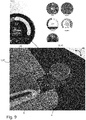
- Figure 9 various representations of possible functions that can be operated with the control element 5 and, if necessary, can also be displayed on this, are shown. For example, the volume of a radio or a telephone to be operated can be adjusted.
- the temperature in the interior area can also be set by turning or by touching the touch-sensitive upper surface 10 of the operating element 5. Ventilation in the interior and for the windows can also be set.
Landscapes
- Engineering & Computer Science (AREA)
- Aviation & Aerospace Engineering (AREA)
- Transportation (AREA)
- Mechanical Engineering (AREA)
- Seats For Vehicles (AREA)
Description
- Die Erfindung betrifft einen Fahrzeugsitz mit einer Bedienungseinrichtung zum Bedienen von Fahrzeugfunktionen, wobei die Bedienungseinrichtung mittels einer Führungseinrichtung an einer Armlehne des Fahrzeugsitzes angeordnet und fest mit dieser verbunden ist und ein an einem Hebelelement angeordnetes Bedienelement umfasst, gemäß dem Oberbegriff des Patentanspruches 1.
- Fahrzeugsitze haben, insbesondere im Nutzfahrzeugbereich, häufig Joysticks und verschiedene Bedienelemente in einem Bereich der rechten Armlehne angeordnet. Dies trifft insbesondere für Traktoren und dergleichen zu. Im Lastkraftwagen-Bereich sind Bedienelemente in der Regel nicht direkt am Fahrzeugsitz bzw. der Armlehne angeordnet, sondern im Armaturenbereich, wie es aus dem Automotive-Bereich bekannt ist.
- Um im Armaturenbereich oder links und rechts vom Lenkrad Bedieninstrumente zu bedienen, ist entweder eine Veränderung der Haltung des Fahrers und damit eine Beeinträchtigung der Fahrsicherheit durch ein Nach-Vorne-Beugen erforderlich, oder das Problem vorhanden, dass zu viele Bedienelemente oder Bedienhebel im Lenkradbereich angeordnet sind, um bei einer Vielzahl von erwünschten zu bedienenden Funktionen zuverlässig den richtigen Hebel oder den richtigen Knopf betätigen zu können.
- Ferner ist der beanspruchbare Bauraum im Armaturenbereich oder links und rechts vom Lenkrad bei der Vielzahl an zu bedienenden Funktionen knapp bemessen Aufgabe der Erfindung ist es demnach, eine Bedieneinrichtung zur Verfügung zu stellen, welche die Bedienung verschiedener Fahrzeugfunktionen ermöglicht und zugleich platzsparend sowie für Bediener einfach erreichbar angeordnet ist.
- Diese Aufgabe wird gelöst von einem Fahrzeugsitz, insbesondere einem Lastkraftwagensitz, mit einer Bedienungseinrichtung zum Bedienen von Fahrzeugfunktionen, wobei die Bedienungseinrichtung mittels einer Führungseinrichtung an einer Armlehne des Fahrzeugsitzes angeordnet und fest mit dieser verbunden ist und ein an einem Hebelelement angeordnetes Bedienelement umfasst. Erfindungsgemäß ist das Hebelelement mittels der Führungseinrichtung entlang einer Längenachse der Armlehne relativ zu der Armlehne bewegbar, wobei das Hebelelement durch eine erste Translationsbewegung entlang der Längenachse nach vorne von einem eingefahrenen Zustand in einen ausgefahrenen Zustand und durch eine zweite Translationsbewegung entlang der Längenachse nach hinten von dem ausgefahrenen Zustand in den eingefahrenen Zustand überführbar ist.
- Durch die an der Armlehne angeordnete erfindungsgemäße Ausbildung einer Bedienungseinrichtung, die ein- und ausziehbar sein kann, ist eine nicht störende Bedienungseinrichtung gegeben, welche jederzeit der Person, die diesen Fahrzeugsitz benutzt, zur Hand ist, also bedient werden kann, ohne dass die Person den Arm von der Armlehne nehmen muss.
- Bei dem Fahrzeugsitz handelt es sich bevorzugt um einen Nutzfahrzeugsitz und besonders bevorzugt um einen Lastkraftwagensitz. Der Fahrzeugsitz ist dabei bevorzugt innerhalb einer Fahrzeugkabine, bevorzugt einer Nutzfahrzeugkabine und besonders bevorzugt einer Lastkraftwagenkabine angeordnet.
- Der Fahrzeugsitz bzw. die Armlehne erstrecken sich entlang einer Höhenachse Z, einer Breitenachse Y und einer Längenachse X, wobei den jeweiligen Achsen jeweils zwei Richtungen zuzuordnen sind. So umfasst die Höhenachse Z die Richtungen Z1 (nach oben) und Z2 (nach unten). Die Breitenachse Y umfasst die Richtungen Y1 (nach rechts) und Y2 (nach links). Die Längenachse X umfasst die Richtungen X1 (nach vorne) und X2 (nach hinten).
- Der verwendete Ausdruck "im Wesentlichen" soll dahingehend auszulegen sein, dass auch geringfügige Toleranzabweichungen mit beansprucht werden. So kann die Abweichung einen Winkel von bevorzugt kleiner 10° weiter bevorzugt kleiner 7,5°, noch weiter bevorzugt kleiner 5° betragen. Dies gilt auch für die im Folgenden verwendeten Ausdrücke "im Wesentlichen".
- Unter Fahrzeugfunktion werden erfindungsgemäß solche Funktionen verstanden, welche Einrichtungen in und/oder am Fahrzeug bzw. mit dem Fahrzeug signaltechnisch verbundene Einrichtungen betreffen. Dabei kann es sich beispielsweise um ein Multimediasystem, eine Klimaanlage, ein mit dem Fahrzeug verbundenes Telefon bzw. Mobiltelefon/Smartphone, Fahrzeugsitzfunktionen, insbesondere eine Sitzhöheneinstellung, sowie eine vertikale Sitzdämpfung, eine Sitzlängsverstellung, eine Rückenlehnenneigung, eine Sitzneigung, eine Sitzklimatisierungseinrichtung, eine Sitzkontureinstellungseinrichtung und/oder eine Massageeinrichtung, oder dergleichen handeln. Diese Aufzählung soll nur beispielhaft sein und nicht als abschließend verstanden werden.
- Erfindungsgemäß handelt es sich bei dem eingefahrenen Zustand um einen Lagerzustand bzw. einen nicht-Verwendungszustand und bei dem ausgefahrenen Zustand um einen Gebrauchszustand bzw. ein Verwendungszustand, in welchem durch die Bedienungseinrichtung bzw. das Bedienelement die entsprechenden Fahrzeugfunktionen eingestellt werden können.
- Bevorzugt ist die Bedienungseinrichtung in die Armlehne des Fahrzeugsitzes integriert, wobei die Bedienungseinrichtung in dem eingefahrenen Zustand einem entsprechenden Oberflächenverlauf der Armlehne angepasst ist. Erfindungsgemäß handelt es sich bei einer festen Verbindung um eine dauerhafte Verbindung, wie eine Schweißverbindung, eine Klebeverbindung, eine Steckverbindung, eine Nietenverbindung, eine Schraubverbindung, eine Bolzenverbindung oder dergleichen.
- Bevorzugt ist die Bedienung der Fahrzeugfunktionen mittels des Bedienelements der Bedienungseinrichtung möglich. Weiterhin ist das Bedienelement durch die Bewegung des damit verbundenen Hebelelements ebenfalls in analoger Weise bewegbar.
- Außerdem ist die Bedienungseinrichtung signaltechnisch mit dem Fahrzeug, dem Fahrzeugsitz bzw. der Fahrzeugelektronik verbunden, um das Bedienen der entsprechenden Fahrzeugfunktionen zu gewährleisten.
- Gemäß einer bevorzugten Ausführungsform ist die Bedienungseinrichtung entlang der Längenachse vorne an der Armlehne angeordnet. Vorzugsweise ist ein Arm eines Bedieners der Bedieneinrichtung bzw. des Fahrzeugsitzes so auf der Armlehne angeordnet, dass sich eine Hand entlang der Längenachse vorne auf der Armlehne und sich ein Ellbogengelenk entlang der Längenachse hinten auf der Armlehne befindet. Durch die bevorzugte Anordnung der Bedienungseinrichtung ist diese für einen Bediener besonders einfach erreichbar.
- Gemäß einer bevorzugten Ausführungsform ist das Bedienelement scheibenartig ausgebildet. Das Bedienelement gemäß Anspruch 1 erstreckt sich im Wesentlichen in der Längenachse und in einer Breitenachse der Armlehne, wobei das Bedienelement bezogen auf eine Höhenachse der Armlehne auf einer oberen Fläche des Hebelelements angeordnet ist. Durch die flache scheibenartige Ausgestaltung des Bedienelements wird der benötigte Bauraum entlang der Höhenachse reduziert.
- Das Bedienelement ist zylinderförmig ausgebildet, wobei eine axiale Richtung des Zylinders parallel zu der Höhenachse angeordnet ist. Die Anordnung des Bedienelements auf dem Hebelelement macht es für einen Bediener besonders einfach bedienbar.
- Eine obere Fläche des Bedienelements welche entlang der Höhenachse nach oben gerichtet ist, ist berührungssensitiv ausgebildet und somit eine Eingabe von verschiedenen Zeichen und das Betätigen verschiedener Funktionen durch Betätigung mittels eines Fingers des Bedieners bzw. des Fahrers ermöglicht. Ferner weist die obere Fläche des Bedienelements ein Display und insbesondere einen Touchscreen, auf, sodass eine direkte Bedienung gewährleistet ist.
- Außerdem ist es denkbar, dass eine Anzeige von getätigten und/oder bedienten Fahrzeugfunktionen durch die Bedienungseinrichtung im vorderen Bereich des Armaturenbrettes, beispielsweise auf einem Display, erfolgt. Dadurch sind die getätigten Einstellungen für den Fahrer leichter ersichtlich und er muss seinen Blick nicht auf die Bedienungseinrichtung richten.
- Gemäß einer bevorzugten Ausführungsform ist das Bedienelement um eine erste Drehachse drehbar mit dem Hebelelement verbunden und die erste Drehachse ist im Wesentlichen senkrecht zu der Längenachse angeordnet. Durch die Drehbewegung des Bedienelements können beispielsweise verschiedene Funktionen ausgewählt werden und/oder eine Betätigung eines Navigationssystems, wie eine Adresseingabe mittels einzelner Buchstaben, durchgeführt werden.
- Gemäß einer bevorzugten Ausführungsform sind das Hebelelement und das Bedienelement in dem eingefahrenen Zustand im Wesentlichen innerhalb der Armlehne und in dem ausgefahrenen Zustand zumindest teilweise außerhalb der Armlehne angeordnet, wobei das Bedienelement im ausgefahrenen Zustand entlang der Längenachse vor der Armlehne angeordnet ist. Auf diese Weise können das Hebelelement und das Bedienelement den Fahrer in einem eingefahrenen Zustand bei nicht-Verwendung nicht behindern und das Bedienelement in dem ausgefahrenen Zustand leicht bedient werden ohne dass der Fahrer seine Position ändern muss.
- Gemäß einer bevorzugten Ausführungsform weist die Führungseinrichtung ein länglich ausgebildetes Führungselement zum Durchführen der ersten und zweiten Translationsbewegung des Hebelelements auf, wobei ein erstes axiales Ende des Führungselements fest mit der Armlehne und ein zweites axiales Ende des Führungselements fest mit dem Hebelelement verbunden ist. Somit ist das Hebelelement durch die Führungseinrichtung bzw. das Führungselement geführt angeordnet. Bevorzugt wird die erste Translationsbewegung in der Längenrichtung nach vorne durch das Führungselement begrenzt. Ebenfalls bevorzugt ist das Führungselement kraftbeaufschlagt, bevorzugt federbeaufschlagt und insbesondere als Federdruckstange, ausgebildet, wobei die Federkraft entlang der Längenachse wirkt und die erste Translationsbewegung dadurch automatisiert ausführbar ist.
- Gemäß einer bevorzugten Ausführungsform ist das Führungselement sich innerhalb der Armlehne entlang des Längenachse der Armlehne erstreckend angeordnet. Somit ist das Führungselement platzsparend und sicher innerhalb der Armlehne angeordnet.
- Gemäß einer bevorzugten Ausführungsform weist die Bedienungseinrichtung eine, ein Arretiermittel und ein Haltemittel umfassende, Arretierungseinrichtung auf, wobei das Arretiermittel fest mit dem Hebelelement und das Haltemittel fest mit der Armlehne verbunden ist. Durch die Arretierungseinrichtung ist die Bewegbarkeit des Hebelelements bei Bedarf einschränkbar, wodurch ein ungewollter Übergang des von dem eingefahrenen Zustand in den ausgefahrenen Zustand verhindert werden kann. Bevorzugt ist die Arretierungseinrichtung so ausgebildet, dass eine Arretierung reversibel durchführbar ist.
- Gemäß einer bevorzugten Ausführungsform ist das Arretiermittel länglich ausgebildet und erstreckt sich entlang der Längenachse nach hinten, wobei das Haltemittel bezogen auf die Höhenachse an einer unteren Fläche der Armlehne angeordnet ist. Durch die beanspruchte Anordnung beeinträchtigt die Arretierungseinrichtung einen Fahrer nicht.
- Gemäß einer bevorzugten Ausführungsform ist die erste Translationsbewegung durch ein Eingreifen des Arretiermittels in das Haltemittel arretierbar. Auf diese Weise ist das Hebelelement innerhalb der Armlehne arretierbar und die erste Translationsbewegung ist unterbunden. Somit ist die Bedienungseinrichtung in dem platzsparenden eingefahrenen Zustand feststellbar und kann erst bei Bedarf ausgefahren werden.
- Es ist ferner denkbar, dass das Hebelelement schwenkbar um eine Achse mit der Armlehne verbunden ist, wobei diese Achse parallel zu der Höhenachse verläuft. Somit wäre eine Rotationsbewegung des Hebelelements in dem ausgefahrenen Zustand relativ zu der Armlehne in einer Ebene in der Breitenachse und der Längenachse nach links und rechts möglich. Auf diese Weise könnte der Bediener bzw. der Fahrer die Bedienungseinrichtung besser erreichen und an seine Bedürfnisse anpassen.
- Ebenso wäre es denkbar, dass das Hebelelement eine weitere Achse aufweist, welche parallel zu der Breitenachse und senkrecht zu der Längenachse angeordnet ist. Diese Achse ist dem Ausgefahrenen Zustand außerhalb der Armlehne angeordnet und ermöglicht eine Rotationsbewegung des Hebelelements in der Ebene der Längenachse und der Höhenachse nach oben und unten. Dadurch kann der Bediener bzw. der Fahrer die Bedienungseinrichtung einfacher erreichen und an seine Armlänge bzw. seine Sitzposition anpassen.
- Weitere Vorteile, Ziele und Eigenschaften der vorliegenden Erfindung werden anhand der anliegenden Figuren und nachfolgender Beschreibung erläutert.
- In den Figuren zeigen:
- Fig. 1
- eine perspektivische Ansicht von schräg hinten einer Armlehne mit der Bedienungseinrichtung in einem ausgefahrenen Zustand nach einer Ausführungsform;
- Fig. 2
- eine Schnittansicht einer Armlehne mit der Bedienungseinrichtung in dem ausgefahrenen Zustand nach einer Ausführungsform;
- Fig. 3
- eine Schnittansicht einer Armlehne mit der Bedienungseinrichtung in dem eingefahrenen Zustand nach einer Ausführungsform;
- Fig. 4
- eine Detailansicht des Arretiermittels nach einer Ausführungsform;
- Fig. 5
- eine Ansicht von unten einer Armlehne mit dem Haltemittel nach einer Ausführungsform;
- Fig. 6
- eine Ansicht von unten einer Armlehne mit der Bedienungseinrichtung und der Arretierungseinrichtung in einem ausgefahrenen Zustand nach einer Ausführungsform;
- Fig. 7
- eine Ansicht von unten einer Armlehne mit der Bedienungseinrichtung und der Arretierungseinrichtung in einem Übergangszustand nach einer Ausführungsform;
- Fig. 8
- eine Ansicht von unten einer Armlehne mit der Bedienungseinrichtung und der Arretierungseinrichtung in einem eingefahrenen Zustand nach einer Ausführungsform;
- Fig. 9
- eine schematische Darstellung der Bedienungseinrichtung an einer Armlehne des Fahrzeugsitzes in einem ausgefahrenen Zustand nach einer Ausführungsform;
- In den
Figuren 1 bis 8 ist eine an eine Armlehne 3 angeordnete Bedienungseinrichtung 2 dargestellt, wobei aus Gründen der Übersichtlichkeit die weiteren Elemente eines Fahrzeugsitzes 1 nicht dargestellt sind. - Die
Figur 1 zeigt die Bedienungseinrichtung 2, welche an der Armlehne 3 angeordnet ist, umfassend ein Hebelelement 4 und ein Bedienelement 5, in einem ausgefahrenen Zustand. - Der Fahrzeugsitz 1 bzw. die Armlehne 3 erstrecken sich entlang einer Höhenachse Z, einer Breitenachse Y und einer Längenachse X, wobei den jeweiligen Achsen jeweils zwei Richtungen zuzuordnen sind. So umfasst die Höhenachse Z die Richtungen Z1 (nach oben) und Z2 (nach unten). Die Breitenachse Y umfasst die Richtungen Y1 (nach rechts) und Y2 (nach links). Die Längenachse X umfasst die Richtungen X1 (nach vorne) und X2 (nach hinten). Außerdem sind die Abbildungen jeweils mit einem entsprechenden kartesischen Koordinatensystem versehen.
- Das Bedienelement 5 ist scheibenartig bzw. zylinder-förmig ausgebildet, wobei es eine obere Fläche 10, welche entlang der Höhenachse Z oben (Richtung Z1) an dem Bedienelement 5 angeordnet ist (Grundfläche des Zylinders) und sich in der Längenachse X und der Breitenachse Y (radiale Richtung des Zylinders) erstreckt, und eine Seitenfläche 11, welche kreisförmig ausgebildet ist und eine Mantelfläche des Zylinders darstellt, aufweist. Das Bedienelement 5 ist über eine Fläche, die der oberen Fläche gegenüberliegend angeordnet ist, drehbar um eine erste Drehachse 12 mit dem Hebelelement 4 verbunden, wobei die erste Drehachse 12 im Wesentlichen senkrecht zu der Längenachse X und parallel zu der Höhenachse Z angeordnet ist und eine Rotationsrichtung 13 im und gegen den Uhrzeigersinn aufweist..
- Dabei ist das Bedienelement 5 auf einer oberen Fläche 6 des Hebelelements 4 angeordnet, welche sich in der Längenachse X und der Breitenachse Y erstreckt und entlang der Höhenachse Z nach oben (Richtung Z1) gerichtet ist. Entlang der Längenachse nach hinten (Richtung X2) ist eine Mittelfläche 9 des Hebelelements 4 benachbart zu der oberen Fläche 6 angeordnet, wobei die Mittelfläche 9 gegenüber der Längenachse X geneigt verläuft und sich in der Längenrichtung X2 (nach hinten) bezogen auf die Höhenachse Z nach unten (Richtung Z2) erstreckt. Die ist nochmals in den
Figuren 2 und3 dargestellt. Das Hebelelement 4 umfasst ferner eine untere Fläche 17, welche parallel zu der oberen Fläche 6 und entlang der Höhenachse Z unten (Richtung Z2) an dem Hebelelement 4 angeordnet ist. - Weiterhin weist das Hebelelement 4 eine Seitenfläche 8 auf, welche sich in der Höhenachse Z und der Längenachse X erstreckt. Benachbart zu der Seitenfläche 8 ist eine Frontfläche 7 des Hebelelements 4 angeordnet, wobei die Frontfläche 7 bogenförmig ausgebildet ist und in der Längenrichtung X vorne (Richtung X1) am Hebelelement angeordnet ist. Die Bogenform der Frontfläche 7 ist komplementär zu dem zylinderförmigen Bedienelement 5 ausgestaltet. Das Bedienelement 5 ist gegenüber der Frontfläche 7 des Hebelelements 4 entlang der Längenachse X nach hinten (Richtung X2) versetzt angeordnet.
- Die Armlehne 3, mit welcher die Bedienungseinrichtung 2 bzw. das Hebelelement 4 fest verbunden ist, weist eine obere Fläche 14 und eine untere Fläche 16, welche sich parallel in der Längenachse X und der Breitenachse Y erstrecken, und eine senkrecht dazu verlaufende Seitenfläche 15, welche sich in der Höhenachse Z und der Längenachse X erstreckt. Die obere Fläche 14 und die untere Fläche 16 erstrecken sich parallel zu der oberen Fläche 10 des Bedienelements 5.
- Die weitere Ausgestaltung der Armlehne 3 ist variabel und richtet sich auch nach der Konstruktion des Fahrzeugsitzes 1 und dem Fahrzeug selbst.
- Die
Figuren 2 ,3 ,5, 6. 7 und 8 zeigen eine Arretierungseinrichtung 18, umfassend ein Arretiermittel 19 und ein Haltemittel 20, wobei die Arretierungseinrichtung 18 im Wesentlichen an der unteren Fläche 16 der Armlehne 3 und der unteren Fläche 17 des Hebelelements 4 angeordnet ist. Ferner ist das Arretiermittel 19 durch eine Zugfeder 21 mit dem Hebelelement 4 verbunden. - In den
Figuren 2 und3 ist jeweils eine Schnittansicht entlang der Längenachse X mittig durch die Armlehne 3 und die Bedienungseinrichtung 2 gezeigt. - Die
Figur 2 zeigt eine Schnittansicht entlang A-A der Armlehne 3 und der Bedienungseinrichtung 2 in dem ausgefahrenen Zustand. - Das Hebelelement 4 weist zusätzlich einen hintere Abschnitt 25 auf, welcher sich im Wesentlichen in der Höhenachse X und der Breitenachse Y erstreckt und benachbart zu der Mittelfläche 9 und der untere Fläche 17 und entlang der Längenachse X hinten (Richtung X2) am Hebelelement 4 angeordnet ist. Ausgehend von der Mittelfläche 9 erstreckt sich der hintere Abschnitt 25 entlang der Höhenachse Z nach oben (Richtung Z1).
- Das zylinderförmige Bedienelement 5 ist entlang der Höhenachse Z teilweise innerhalb des Hebelelements 4 angeordnet, wobei das Bedienelement 5 entlang der Höhenachse Z nach oben (Richtung Z1) aus dem Hebelelement herausragt und die Seitenfläche 11 teilweise sowie die obere Fläche 10 vollständig außerhalb des Hebelelements 4 angeordnet sind. Weiterhin ist eine Führungseinrichtung 22 gezeigt, welche ein längliches sich in der Längenachse X erstreckendes Führungselement 23 aufweist. Das Führungselement 23 ist mit einem ersten axialen Ende 26a mit der Armlehne 3 und einem zweiten axialen Ende 26b mit dem Hebelelement 4 bzw. dem hinteren Abschnitt 25 verbunden. Gemäß der Ausführungsform ist das Führungselement 23 als Federdruckstab ausgebildet. Dabei ist ein inneres Stabelement 23b bewegbar entlang der Längenachse X teilweise innerhalb eines äußeren Stabelements 23a angeordnet. Das erste axiale Ende 26a ist an dem äußeren Stabelement 23a und das zweite axiale Ende 26b an dem inneren Stabelement 23b angeordnet. Eine Druckfeder 24 ist am ersten axialen Ende 26a innerhalb des äußeren Stabelements 23a angeordnet, wobei die axiale Richtung der Druckfeder 24 parallel zu der Längenachse X verläuft und die Druckfeder 24 die erste Translationsbewegung des Hebelelements 4 entlang der Längenachse X nach vorne (Richtung X1) kraftbeaufschlagt. In dem ausgefahrenen Zustand weist die Druckfeder 24 ihre maximale Ausdehnung auf. Beim Übergang von dem eingefahrenen Zustand in den ausgefahrenen Zustand verschiebt sich das innere Stabelement 23b relativ zu dem äußeren Stabelement 23a entlang der Längenachse X nach vorne (Richtung X1) aus dem äußeren Stabelement 23a hinaus.
- In dem ausgefahrenen Zustand ist das Bedienelement 5 vollständig außerhalb der Armlehne 3 angeordnet, wobei der hintere Abschnitt 25 des Hebelelements 4 innerhalb der Armlehne 3 verbleibt.
- Die
Figur 3 zeigt eine Schnittansicht entlang B-B der Armlehne 3 und der Bedienungseinrichtung 2 in dem eingefahrenen Zustand. - Wie gezeigt, sind das Hebelelement 4 und das Bedienelement 5 in dem eingefahrenen Zustand vollständig innerhalb der Armlehne 3, im Wesentlichen zwischen der oberen Fläche 14 und der unteren Fläche 16, angeordnet. In dem eingefahrenen Zustand ist die Frontfläche 7 des Hebelelements 4 entlang der Längenachse X bündig zu der oberen Fläche 14 und der unteren Fläche 16 des Hebelelements 4 angeordnet, wobei die Frontfläche 7 des Hebelelements 4 zumindest teilweise eine Frontfläche der Armlehne 3 ausbildet. Die obere Fläche 10 des Bedienelements 5 ist in dem eingefahrenen Zustand benachbart zu der oberen Fläche 14 bzw. einer Innenseite der oberen Fläche 14 der Armlehne angeordnet, wobei die untere Fläche 17 des Hebelelements 4 benachbart zu der untere Fläche 16 der Armlehne 3 angeordnet ist.
- Ferner ist das innere Stabelement 23b in dem eingefahrenen Zustand hauptsächlich innerhalb dem äußeren Stabelement 23a angeordnet und im Vergleich zu dem eingefahrenen Zustand entlang der Längenachse X nach hinten (Richtung X2) versetzt. Die Druckfeder 24 ist im eingefahrenen Zustand komprimiert.
- In der
Figur 4 ist eine Detailansicht des Arretiermittels 19 dargestellt. Das Arretiermittel 19 ist länglich ausgebildet weist einen Führungsabschnitt 30 und einen Rastabschnitt 31 aus, wobei der Führungsabschnitt 30 entlang der Längenachse X in der Längenrichtung X1 (nach vorne) vor dem Rastabschnitt 31 angeordnet ist. Ferner ist das Rastabschnitt 31 entlang der Höhenachse Z nach unten (Richtung Z2) versetzt zu dem Führungsabschnitt 30 angeordnet. Der Rastabschnitt 31 ist mittels einer dritten Achse 32 schwenkbar mit dem Führungsabschnitt 30 verbunden. - An dem Rastabschnitt 31 ist ferner ein mittels einer zweiten Achse 28 schwenkbar angeordnetes Rastelement 27 vorgesehen. Die zweite Achse 28 und die dritte Achse 32 erstrecken sich parallel zueinander in der Höhenachse Z senkrecht zu der Längenachse X, wobei die zweite Achse 28 und die dritte Achse 32 entlang der Längenachse X beabstandet auf dem Rastabschnitt 31 angeordnet sind. Weiterhin ist ein erstes Stiftelement 29 auf dem Rastabschnitt 31 zwischen der zweiten Achse 28 und der dritten Achse 32 angeordnet, der sich entlang der Höhenachse Z nach unten (Richtung Z2) erstreckt. Das Rastelement 27 ist im Wesentlichen dreieckig ausgebildet.
- Die
Figur 5 zeigt eine Ansicht von unten entlang der Höhenachse Z der Armlehne 3 und des Haltemittels 20. Die Bedienungseinrichtung 2 und das Arretiermittel 19 sind nicht dargestellt. - Das Haltemittel 20 ist an der unteren Fläche 16 der Armlehne 3 angeordnet und fest mit dieser verbunden. Das Haltemittel 20 umfasst ein äußeres Kulissenelement 33a und ein von dem äußeren Kulissenelement 33a zumindest teilweise umgebenes inneres Kulissenelement 33b. Durch das äußere Kulissenelement 38a ist das Arretiermittel 19 bzw. das Rastelement 27 führbar, wobei es durch das innere Kulissenelement 33b arretierbar ist.
- Das äußere Kulissenelement 33a weist einen sich entlang der Längenachse X erstreckenden länglichen ersten Abschnitt 34a auf, wobei sich ausgehend von diesem ersten Abschnitt 34a an dessen hinteren (Richtung X2) Endbereich ein zweiter Abschnitt 34b nach rechts (Richtung Y1) verjüngend entlang der Breitenachse Y erstreckt. Ferner erstreckt sich von diesem zweiten Abschnitt 34b ein dritter Abschnitt 34c nach rechts (Richtung Y1) verjüngend entlang der Breitenachse Y, wobei der zweite Abschnitt 34b und der dritte Abschnitt 34c an ihrer Verbindungsstelle einen stufenförmigen Vorsprung 35 ausbilden. Ausgehend von dem dritten Abschnitt 34c erstreckt sich ein vierter Abschnitt 34d entlang der Längenachse X nach vorne (Richtung X1), wobei die Erstreckung des vierten Abschnitts 34d entlang der Längenachse X der Erstreckung des ersten Abschnitts 34a entlang der Längenachse X entspricht.
- Das innere Kulissenelement 33b ist in Bezug auf den zweiten Abschnitt 34b und den dritten Abschnitt 34c des äußeren Kulissenelements 33a entlang der Längenachse X nach vorne (Richtung X1) versetzt angeordnet. Weiterhin ist das innere Kulissenelement 33b entlang der Breitenachse Y zwischen dem ersten Abschnitt 34a und dem vierten Abschnitt 34d des äußeren Kulissenelements 33a angeordnet. Das innere Kulissenelement 33b ist im Wesentlichen polygon-förmig ausgebildet und weist eine dem zweiten 34b und dritten Abschnitt 34c zugewandte Aussparung 36 auf. Diese Aussparung 36 ist im Wesentlichen komplementär zu dem Rastelement 27 ausgebildet.
- Außerdem ist die Zugfeder 21 mit einem ersten axialen Ende mit dem Arretiermittel 19, genauer mit dem ersten Stiftelement 29, und mit einem zweiten axialen Ende mit dem Hebelelement 4, genauer mit einem zweiten Stiftelement 44, welches an der unteren Fläche 17 angeordnet ist und sich entlang der Höhenachse Z nach unten (Richtung Z2) erstreckt, verbunden.
- Weiterhin weist die untere Fläche 16 der Armlehne 3 vorne (Richtung X1) eine im Wesentlichen T-förmige Aussparung 37 auf, welche einen breiten Aufnahmebereich 37a und einen schmalen Führungsbereich 37b umfasst, wobei der Führungsbereich 37b entlang der Längenachse hinter (Richtung X2) dem Aufnahmebereich 37a angeordnet ist. Der Aufnahmebereich 37a erstreckt sich in der Breitenrichtung Y nicht über die gesamte Breite der unteren Fläche 16, wodurch links und rechts Randabschnitte 38a, 38b erhalten bleiben, wobei das Hebelelement 4 auf diesen Randabschnitten 38a, 38b ruht bzw. gleitet. Durch den Aufnahmebereich 37a der Aussparung 37 wird eine Reibung verringert und die Translationsbewegungen können ungehindert stattfinden. Der Führungsbereich 37b der Aussparung 37 nimmt in dem eingefahrenen Zustand den Führungsabschnitt 30 des Arretiermittels 19 auf. Der Führungsbereich 37b der Aussparung 37 führt den Führungsabschnitt 30 des Arretiermittels 19.
- In der
Figur 6 ist der Arretierungsvorgang durch die Arretierungseinrichtung 18 dargestellt, wobei eine Bewegung der Elemente durch Pfeile 39-43 angedeutet ist. - Um eine Arretierung der Bedienungseinrichtung 2 bzw. des Hebelelements 4 zu erreichen, erfolgt eine translatorische Verschiebung (zweite Translationsbewegung) des Hebelelements 4 in Pfeilrichtung 39 (Längenrichtung X2), wobei das Arretiermittel 20 bzw. der Rastabschnitt 31 durch die Zugfeder 21, welche den Rastabschnitt 31 in Breitenrichtung Y2 (nach links) um die dritte Achse 32 verschwenkt bis die Rotation durch den ersten Abschnitt 34a des äußeren Kulissenelements 33a begrenzt wird, bezogen auf die Breitenachse Y links des inneren Kulissenelements 33b, geführt durch den ersten Abschnitt 34a des äußeren Kulissenelements 33a, in der Längen-richtung X2 (nach hinten) an dem inneren Kulissenelement 33b vorbeigeführt wird. Ferner wird das Arretiermittel 19 bzw. das Rastelement 27 durch den zweiten Abschnitt 34b des äußeren Kulissenelements 33a entlang der Breitenachse Y nach rechts (Breitenrichtung Y1) geführt bis das Rastelement 27 kontaktierend zu dem stufenförmigen Vorsprung 35 angeordnet ist und die Bewegung in Breitenrichtung Y1 begrenzt wird, wobei das Rastelement 27 nach einer Bewegung in Pfeilrichtung 41 in die komplementäre Aussparung 36 eingreifen kann.
- Das Rastelement 27 greift in einem arretierenden Zustand in die Aussparung 36 des inneren Kulissenelements 33b des Haltemittels 20 ein.
- Eine translatorische Verschiebung (erste Translationsbewegung), beispielsweise ausgelöst durch einen Bediener bzw. Fahrer durch eine Kraftbeaufschlagung der Frontfläche 7 des Hebelelements 4 entlang der Pfeilrichtung 39 (entlang der Längenachse X nach hinten, Längenrichtung X2) verursacht eine translatorische Verschiebung des Arretiermittels 19 entlang der Pfeilrichtung 39 entlang der Längenachse X in Längenrichtung X2 (nach hinten). Dadurch wird der Eingriff des Rastelements 27 in die Aussparung 35 des inneren Kulissenelementes 33b gelöst und das Arretiermittel 19 wird über das Rastelement 27 durch den dritten Abschnitt 34c des äußeren Kulissenelements 33a entlang der Pfeilrichtung 42 nach rechts (Breitenrichtung Y1) geführt, wobei sich das schwenkbar um die zweite Achse 28 gelagerte Rastelement 27 und der schwenkbar um die dritte Achse 32 gelagerte Rastabschnitt 31 der jeweiligen Neigung der Abschnitte 34a-c anpassen kann. Folglich ist das Arretiermittel 19 entlang der Pfeilrichtung 43 in Längenrichtung X1 (nach vorne) in Bezug auf die Breitenachse Y rechts (Richtung Y1) an dem inneren Kulissenelement 33b vorbeibewegbar, was der ersten Translationsbewegung des Hebelelements 4 entspricht. Somit ist die erste Translationsbewegung des Hebelelements 4 freigegeben.
- Die
Figuren 7 und 8 zeigen die Armlehne 3 mit der Bedienungseinrichtung 2 und der Arretierungseinrichtung 18. - Die
Figur 7 zeigt dabei den Übergang von dem ausgefahrenen Zustand in den eingefahrenen Zustand (Übergang in den arretierten Zustand). Das Rastelement 27 wird durch den ersten Abschnitt 34a in der Breitenachse links (Richtung Y2) an dem inneren Kulissenelement 33b vorbeigeführt, wobei die Zugfeder 21 die Positionierung des Rastelements 27 kontaktierend zu dem ersten Abschnitt 34a gewährleiste. Eine Rotation des Rastabschnittes 31 um die dritte Achse 32 ermöglicht die Arretierung zusätzlich. - In
Figur 8 wird hingegen der Übergang aus dem eingefahrenen Zustand in den ausgefahrenen Zustand (Übergang in den nicht-arretierten Zustand) dargestellt, wobei das Rastelement 27 bezogen auf die Breitenachse Y rechts an dem inneren Kulissenelement 33a vorbeigeführt wird. Zum Lösen der Arretierung wird das Hebelelement 4 in der Längenrichtung X nach hinten in die Armlehne gedrückt, wobei die Frontfläche 7 gegenüber der oberen Fläche 14 und der unteren Fläche 16 der Armlehne 3 in der Längenrichtung X nach hinten versetzt ist. - In
Figur 9 ist die Bedienungseinrichtung 2, welche an einer Armlehne 3 eines eine Sitzfläche 47 umfassenden Fahrzeugsitzes 1 angeordnet ist, nochmals wiedergegeben. Diese umfasst, wie bereits erwähnt, ein an einem Hebelelement 4 angeordnetes Bedienelement 5. Das Hebelelement 4 ist entlang der Längenachse X nach vorne (Richtung X1) und nach hinten (Richtung X2) gemäß Pfeil 45 gegenüber der Armlehne 3 verschiebbar. - Es ist denkbar, dass das Hebelelement 4 in dem ausgefahrenen Zustand auch gegenüber der Armlehne 3 in der Breitenachse Y verschwenkt werden kann, wie es durch einen Doppelpfeil 46 wiedergegeben wird. Denkbar ist auch ein Verschwenken des Hebelelements 4 nach oben und unten entlang der Höhenachse Z. Das Bedienelement 5 ist drehbar in dem Hebelelement 4 angeordnet, sodass durch eine Drehbewegung verschiedene Funktionen, wie beispielsweise die Betätigung eines Navigationssystems, wie eine Adresseingabe mittels einzelner Buchstaben, durchgeführt werden kann.
- Das Bedienelement 5 ist ebenso, wie in
Figur 9 dargestellt, oberseitig 10 mit einer Bedienfläche ausgestattet, die berührungssensitiv ausgebildet ist und die Eingabe von verschiedenen Zeichen und das Betätigen verschiedener Funktionen durch Betätigung mittels eines Fingers des Fahrers ermöglicht. - Ebenso kann die obere Fläche 10 des Bedienelementes 5 mit einer Anzeigeeinrichtung, beispielsweise mit einem Touchscreen in Form eines Displays ausgebildet sein, sodass eine direkte Bedienung auf dieser Bedienfläche möglich ist.
- Alternativ oder zusätzlich kann eine Anzeige von getätigten und bedienten Funktionen auf dem Bedienelement 5 im vorderen Bereich des Armaturenbrettes, also auf einem Display, erfolgen.
- In
Figur 9 sind verschiedene Darstellungen möglicher Funktionen, die mit dem Bedienelement 5 bedient werden können und gegebenenfalls auch auf diesem angezeigt werden können, dargestellt. Beispielsweise kann die Lautstärke eines Radios oder eines zu bedienenden Telefons eingestellt werden. - Es kann auch die Temperatur im Innenbereich durch Drehen oder durch Berührung der Touch-sensitiven oberen Fläche 10 des Bedienelementes 5 eingestellt werden. Ebenso ist eine Lüftung im Innenraum und für die Scheiben einstellbar.
- Es können auch weitere Einstellungen, wie eine Armlehnenveränderung, insbesondere eine Höheneinstellung oder ein Nach-Vorne-Schieben oder Nach-Hinten-Schieben oder ein Verschwenken des Fahrzeugsitzes denkbar sein.
- Aus Gründen der Übersicht können in den Figuren jeweils nur die relevanten Merkmale mit Bezugszeichen versehen sein.
- Die Ausführungen und Beschreibungen zu Merkmalen/Elementen, welche in einer der Figuren gezeigt werden, sollen mutatis mutandis auch für das entsprechende Merkmal/Element gelten, falls es in einer anderen Figur gezeigt ist.
- Es versteht sich, dass es sich bei den vorstehend erläuterten Ausführungsbeispielen lediglich um eine erste Ausgestaltung des erfindungsgemäßen Fahrzeugsitzes bzw. der Bedienungseinrichtung handelt. Insofern beschränkt sich die Ausgestaltung der Erfindung nicht auf diese Ausführungsbeispiele.
-
- 1
- Fahrzeugsitz
- 2
- Bedienungseinrichtung
- 3
- Armlehne
- 4
- Hebelelement
- 5
- Bedienelement
- 6
- obere Fläche des Hebelelements
- 7
- Frontfläche des Hebelelements
- 8
- Seitenfläche des Hebelelements
- 9
- Mittelfläche des Hebelelements
- 10
- obere Fläche des Bedienelements
- 11
- Seitenfläche des Bedienelements
- 12
- erste Drehachse
- 13
- Rotationsrichtung
- 14
- obere Fläche der Armlehne
- 15
- Seitenfläche der Armlehne
- 16
- untere Fläche der Armlehne
- 17
- untere Fläche des Hebelelements
- 18
- Arretierungseinrichtung
- 19
- Arretiermittel
- 20
- Haltemittel
- 21
- Zugfeder
- 22
- Führungseinrichtung
- 23
- Führungselement
- 24
- Druckfeder
- 25
- hinterer Abschnitt
- 26a
- erster axiales Ende
- 26b
- zweites axiales Ende
- 27
- Rastelement
- 28
- zweite Achse
- 29
- erstes Stiftelement
- 30
- Führungsabschnitt
- 31
- Rastabschnitt
- 32
- dritte Achse
- 33a
- äußeres Kulissenelement
- 33b
- inneres Kulissenelement
- 34a-d
- erster bis vierter Abschnitt
- 35
- stufenförmiger Abschnitt
- 36
- Aussparung
- 37
- T-förmige Aussparung
- 37a
- Aufnahmebereich
- 37b
- Führungsbereich
- 38a,b
- Randabschnitt
- 39
- Pfeil
- 40
- Pfeil
- 41
- Pfeil
- 42
- Pfeil
- 43
- Pfeil
- 44
- zweites Stiftelement
- 45
- Pfeil
- 46
- Pfeil
- 47
- Sitzfläche
Claims (8)
- Fahrzeugsitz (1), insbesondere ein Lastkraftwagensitz, mit einer Bedienungseinrichtung (2) zum Bedienen von Fahrzeugfunktionen, wobei die Bedienungseinrichtung (2) mittels einer Führungseinrichtung (22) an einer Armlehne (3) des Fahrzeugsitzes (1) angeordnet und fest mit dieser verbunden ist und ein an einem Hebelelement (4) angeordnetes Bedienelement (5) umfasst, wobei das Hebelelement (4) mittels der Führungseinrichtung (22) entlang einer Längenachse (X) der Armlehne (3) relativ zu der Armlehne (3) bewegbar ist, wobei das Hebelelement (4) durch eine erste Translationsbewegung entlang der Längenachse (X) nach vorne (X1) von einem eingefahrenen Zustand in einen ausgefahrenen Zustand und durch eine zweite Translationsbewegung entlang der Längenachse (X) nach hinten (X2) von dem ausgefahrenen Zustand in den eingefahrenen Zustand überführbar ist,
dadurch gekennzeichnet, dass
das Bedienelement (5) kreiszylinderförmig ausgebildet ist und sich im Wesentlichen in der Längenachse (X) und in einer Breitenachse (Y) der Armlehne (3) erstreckt, wobei das Bedienelement (5) bezogen auf eine Höhenachse (Z) der Armlehne (3) auf einer oberen Fläche (6) des Hebelelements (4) angeordnet ist, wobei das Bedienelement (5) um eine erste Drehachse (12) drehbar mit dem Hebelelement (4) verbunden ist und die erste Drehachse (12) im Wesentlichen parallel zu der Höhenachse (Z) angeordnet ist, wobei durch eine Drehbewegung des Bedienelements (5) eine Auswahl einer Funktion erfolgen kann, wobei eine obere Fläche (10) des Bedienelements (5) ein Display und eine berührungssensitive Bedienfläche umfasst. - Fahrzeugsitz nach Anspruch 1,
dadurch gekennzeichnet, dass
die Bedienungseinrichtung (2) entlang der Längenachse (X) vorne (X1) an der Armlehne (3) angeordnet ist. - Fahrzeugsitz nach einem der vorangegangenen Ansprüche,
dadurch gekennzeichnet, dass
das Hebelelement (4) und das Bedienelement (5) in dem eingefahrenen Zustand im Wesentlichen innerhalb der Armlehne (3) und in dem ausgefahrenen Zustand zumindest teilweise außerhalb der Armlehne (3) angeordnet sind, wobei das Bedienelement (5) im ausgefahrenen Zustand entlang der Längenachse (X) vor der Armlehne (3) angeordnet ist. - Fahrzeugsitz nach einem der vorangegangenen Ansprüche,
dadurch gekennzeichnet, dass
die Führungseinrichtung (22) ein länglich ausgebildetes Führungselement (23) zum Durchführen der ersten und zweiten Translationsbewegung des Hebelelements (4) aufweist, wobei ein erstes axiales Ende (26a) des Führungselements (23) fest mit der Armlehne (3) und ein zweites axiales Ende (26b) des Führungselements (23) fest mit dem Hebelelement (4) verbunden ist. - Fahrzeugsitz nach Anspruch 4,
dadurch gekennzeichnet, dass
das Führungselement (23) sich innerhalb der Armlehne entlang des Längenachse (X) der Armlehne (3) erstreckend angeordnet ist. - Fahrzeugsitz nach einem der vorangegangenen Ansprüche,
dadurch gekennzeichnet, dass
die Bedienungseinrichtung (2) eine, ein Arretiermittel (19) und ein Haltemittel (20) umfassende, Arretierungseinrichtung (18) aufweist, wobei das Arretiermittel (19) fest mit dem Hebelelement (4) und das Haltemittel (20) fest mit der Armlehne (3) verbunden ist. - Fahrzeugsitz nach Anspruch 6,
dadurch gekennzeichnet, dass
das Arretiermittel (19) länglich ausgebildet ist und sich entlang der Längenachse (X) nach hinten (X2) erstreckt, wobei das Haltemittel (20) in der Höhenachse (Z) an einer unteren Fläche (16) der Armlehne (3) angeordnet ist. - Fahrzeugsitz nach Anspruch 6 oder 7,
dadurch gekennzeichnet, dass
die erste Translationsbewegung durch ein Eingreifen des Arretiermittels (19) in das Haltemittel (20) arretierbar ist.
Applications Claiming Priority (2)
| Application Number | Priority Date | Filing Date | Title |
|---|---|---|---|
| DE102018123009 | 2018-09-19 | ||
| DE102019122539.6A DE102019122539A1 (de) | 2018-09-19 | 2019-08-21 | Fahrzeugsitz mit Bedienungseinrichtung |
Publications (2)
| Publication Number | Publication Date |
|---|---|
| EP3626525A1 EP3626525A1 (de) | 2020-03-25 |
| EP3626525B1 true EP3626525B1 (de) | 2021-12-29 |
Family
ID=67953550
Family Applications (1)
| Application Number | Title | Priority Date | Filing Date |
|---|---|---|---|
| EP19196573.0A Active EP3626525B1 (de) | 2018-09-19 | 2019-09-10 | Fahrzeugsitz mit bedienungseinrichtung |
Country Status (1)
| Country | Link |
|---|---|
| EP (1) | EP3626525B1 (de) |
Families Citing this family (2)
| Publication number | Priority date | Publication date | Assignee | Title |
|---|---|---|---|---|
| DE102019213846A1 (de) * | 2019-09-11 | 2021-03-11 | Zf Friedrichshafen Ag | Kraftfahrzeug |
| DE102020117691A1 (de) * | 2020-07-06 | 2022-01-13 | Grammer Aktiengesellschaft | Lenkvorrichtung für Fahrzeuge |
Family Cites Families (2)
| Publication number | Priority date | Publication date | Assignee | Title |
|---|---|---|---|---|
| US4669780A (en) * | 1984-07-31 | 1987-06-02 | Nippon Soken, Inc. | Device for controlling power seats in vehicle |
| FI77334C (fi) * | 1987-03-03 | 1989-02-10 | Teopros Oy | Styranordning. |
-
2019
- 2019-09-10 EP EP19196573.0A patent/EP3626525B1/de active Active
Also Published As
| Publication number | Publication date |
|---|---|
| EP3626525A1 (de) | 2020-03-25 |
Similar Documents
| Publication | Publication Date | Title |
|---|---|---|
| DE102019122539A1 (de) | Fahrzeugsitz mit Bedienungseinrichtung | |
| EP2834099B1 (de) | Verstellvorrichtung für ein schwenkbares komfortelement, insbesondere für eine armlehne eines fahrzeugs | |
| DE102014224560A1 (de) | Anordnung für einen Fahrzeuginnenraum, Kraftfahrzeug | |
| DE102013221925B3 (de) | Beschlag mit einem Vorschwenkmechanismus und einer Easy-Entry-Klinke, Easy-Entry-Klinke für einen solchen Beschlag sowie Fahrzeugsitz mit einem solchen Beschlag | |
| EP3626525B1 (de) | Fahrzeugsitz mit bedienungseinrichtung | |
| EP3381725B1 (de) | Luftausströmer | |
| WO2021214127A1 (de) | Fahrzeugsitz mit einem kinematikhebel | |
| EP2769282B1 (de) | Bedieneinrichtung für fahrzeuge | |
| EP1295753B1 (de) | Gelenkbeschlag für einen Kraftfahrzeugsitz mit vorkippbarer Rückenlehne | |
| EP3140154B1 (de) | Entriegelungshebel für eine sitzverstellung eines fahrzeugsitzes und fahrzeugsitz | |
| WO2014090736A1 (de) | Verschwenkbare armlehne, insbesondere mittelarmlehne für ein kraftfahrzeug | |
| DE102010020633A1 (de) | Lenksäule für ein Kraftfahrzeug | |
| DE102004005705B4 (de) | Rückenlehne für einen Fahrzeugsitz und Fahrzeugsitz | |
| WO2007118505A1 (de) | Verstellsystem für einen fahrzeugsitz | |
| EP3835120B1 (de) | Sitzvorrichtung für eine baumaschine | |
| DE19513249C1 (de) | Kraftfahrzeug-Türgriff | |
| DE102017206414A1 (de) | Bedienvorrichtung für ein Kraftfahrzeug und Verfahren zum Betreiben eines Kraftfahrzeugs mittels einer Bedienvorrichtung | |
| DE102011120881A1 (de) | Verstaueinrichtung für einen Innenraum eines Kraftwagens | |
| DE102018110137B4 (de) | Innenraumkomponente für ein Kraftfahrzeug | |
| EP3118046B1 (de) | Bedienvorrichtung eines kraftfahrzeugs für die manuelle betätigung eines gaspedals und eines bremspedals | |
| DE102014212598B4 (de) | Verstellbarer Fahrzeugsitz | |
| EP1968815B1 (de) | Kraftfahrzeugsitz mit einer kopplung zwischen der rückenlehnen- und der sitzteilbewegung und kraftfahrzeug mit einem solchen kraftfahrzeugsitz | |
| EP3626538B1 (de) | Konsoleneinrichtung für nutzfahrzeugkabine | |
| DE102023001993B3 (de) | Steer-by-Wire-Lenkrad für einen Kraftwagen sowie Verfahren | |
| EP2353949A2 (de) | Betätigungsvorrichtung für eine Feststellbremse |
Legal Events
| Date | Code | Title | Description |
|---|---|---|---|
| PUAI | Public reference made under article 153(3) epc to a published international application that has entered the european phase |
Free format text: ORIGINAL CODE: 0009012 |
|
| STAA | Information on the status of an ep patent application or granted ep patent |
Free format text: STATUS: THE APPLICATION HAS BEEN PUBLISHED |
|
| AK | Designated contracting states |
Kind code of ref document: A1 Designated state(s): AL AT BE BG CH CY CZ DE DK EE ES FI FR GB GR HR HU IE IS IT LI LT LU LV MC MK MT NL NO PL PT RO RS SE SI SK SM TR |
|
| AX | Request for extension of the european patent |
Extension state: BA ME |
|
| STAA | Information on the status of an ep patent application or granted ep patent |
Free format text: STATUS: REQUEST FOR EXAMINATION WAS MADE |
|
| RAP1 | Party data changed (applicant data changed or rights of an application transferred) |
Owner name: GRAMMER AG |
|
| 17P | Request for examination filed |
Effective date: 20200914 |
|
| RBV | Designated contracting states (corrected) |
Designated state(s): AL AT BE BG CH CY CZ DE DK EE ES FI FR GB GR HR HU IE IS IT LI LT LU LV MC MK MT NL NO PL PT RO RS SE SI SK SM TR |
|
| GRAP | Despatch of communication of intention to grant a patent |
Free format text: ORIGINAL CODE: EPIDOSNIGR1 |
|
| STAA | Information on the status of an ep patent application or granted ep patent |
Free format text: STATUS: GRANT OF PATENT IS INTENDED |
|
| INTG | Intention to grant announced |
Effective date: 20210916 |
|
| GRAS | Grant fee paid |
Free format text: ORIGINAL CODE: EPIDOSNIGR3 |
|
| GRAA | (expected) grant |
Free format text: ORIGINAL CODE: 0009210 |
|
| STAA | Information on the status of an ep patent application or granted ep patent |
Free format text: STATUS: THE PATENT HAS BEEN GRANTED |
|
| AK | Designated contracting states |
Kind code of ref document: B1 Designated state(s): AL AT BE BG CH CY CZ DE DK EE ES FI FR GB GR HR HU IE IS IT LI LT LU LV MC MK MT NL NO PL PT RO RS SE SI SK SM TR |
|
| REG | Reference to a national code |
Ref country code: GB Ref legal event code: FG4D Free format text: NOT ENGLISH |
|
| REG | Reference to a national code |
Ref country code: CH Ref legal event code: EP |
|
| REG | Reference to a national code |
Ref country code: AT Ref legal event code: REF Ref document number: 1458442 Country of ref document: AT Kind code of ref document: T Effective date: 20220115 |
|
| REG | Reference to a national code |
Ref country code: IE Ref legal event code: FG4D Free format text: LANGUAGE OF EP DOCUMENT: GERMAN |
|
| REG | Reference to a national code |
Ref country code: DE Ref legal event code: R096 Ref document number: 502019003095 Country of ref document: DE |
|
| REG | Reference to a national code |
Ref country code: LT Ref legal event code: MG9D |
|
| PG25 | Lapsed in a contracting state [announced via postgrant information from national office to epo] |
Ref country code: RS Free format text: LAPSE BECAUSE OF FAILURE TO SUBMIT A TRANSLATION OF THE DESCRIPTION OR TO PAY THE FEE WITHIN THE PRESCRIBED TIME-LIMIT Effective date: 20211229 Ref country code: LT Free format text: LAPSE BECAUSE OF FAILURE TO SUBMIT A TRANSLATION OF THE DESCRIPTION OR TO PAY THE FEE WITHIN THE PRESCRIBED TIME-LIMIT Effective date: 20211229 Ref country code: FI Free format text: LAPSE BECAUSE OF FAILURE TO SUBMIT A TRANSLATION OF THE DESCRIPTION OR TO PAY THE FEE WITHIN THE PRESCRIBED TIME-LIMIT Effective date: 20211229 Ref country code: BG Free format text: LAPSE BECAUSE OF FAILURE TO SUBMIT A TRANSLATION OF THE DESCRIPTION OR TO PAY THE FEE WITHIN THE PRESCRIBED TIME-LIMIT Effective date: 20220329 |
|
| REG | Reference to a national code |
Ref country code: NL Ref legal event code: MP Effective date: 20211229 |
|
| PG25 | Lapsed in a contracting state [announced via postgrant information from national office to epo] |
Ref country code: SE Free format text: LAPSE BECAUSE OF FAILURE TO SUBMIT A TRANSLATION OF THE DESCRIPTION OR TO PAY THE FEE WITHIN THE PRESCRIBED TIME-LIMIT Effective date: 20211229 Ref country code: NO Free format text: LAPSE BECAUSE OF FAILURE TO SUBMIT A TRANSLATION OF THE DESCRIPTION OR TO PAY THE FEE WITHIN THE PRESCRIBED TIME-LIMIT Effective date: 20220329 Ref country code: LV Free format text: LAPSE BECAUSE OF FAILURE TO SUBMIT A TRANSLATION OF THE DESCRIPTION OR TO PAY THE FEE WITHIN THE PRESCRIBED TIME-LIMIT Effective date: 20211229 Ref country code: HR Free format text: LAPSE BECAUSE OF FAILURE TO SUBMIT A TRANSLATION OF THE DESCRIPTION OR TO PAY THE FEE WITHIN THE PRESCRIBED TIME-LIMIT Effective date: 20211229 Ref country code: GR Free format text: LAPSE BECAUSE OF FAILURE TO SUBMIT A TRANSLATION OF THE DESCRIPTION OR TO PAY THE FEE WITHIN THE PRESCRIBED TIME-LIMIT Effective date: 20220330 |
|
| PG25 | Lapsed in a contracting state [announced via postgrant information from national office to epo] |
Ref country code: NL Free format text: LAPSE BECAUSE OF FAILURE TO SUBMIT A TRANSLATION OF THE DESCRIPTION OR TO PAY THE FEE WITHIN THE PRESCRIBED TIME-LIMIT Effective date: 20211229 |
|
| PG25 | Lapsed in a contracting state [announced via postgrant information from national office to epo] |
Ref country code: SM Free format text: LAPSE BECAUSE OF FAILURE TO SUBMIT A TRANSLATION OF THE DESCRIPTION OR TO PAY THE FEE WITHIN THE PRESCRIBED TIME-LIMIT Effective date: 20211229 Ref country code: SK Free format text: LAPSE BECAUSE OF FAILURE TO SUBMIT A TRANSLATION OF THE DESCRIPTION OR TO PAY THE FEE WITHIN THE PRESCRIBED TIME-LIMIT Effective date: 20211229 Ref country code: RO Free format text: LAPSE BECAUSE OF FAILURE TO SUBMIT A TRANSLATION OF THE DESCRIPTION OR TO PAY THE FEE WITHIN THE PRESCRIBED TIME-LIMIT Effective date: 20211229 Ref country code: PT Free format text: LAPSE BECAUSE OF FAILURE TO SUBMIT A TRANSLATION OF THE DESCRIPTION OR TO PAY THE FEE WITHIN THE PRESCRIBED TIME-LIMIT Effective date: 20220429 Ref country code: ES Free format text: LAPSE BECAUSE OF FAILURE TO SUBMIT A TRANSLATION OF THE DESCRIPTION OR TO PAY THE FEE WITHIN THE PRESCRIBED TIME-LIMIT Effective date: 20211229 Ref country code: EE Free format text: LAPSE BECAUSE OF FAILURE TO SUBMIT A TRANSLATION OF THE DESCRIPTION OR TO PAY THE FEE WITHIN THE PRESCRIBED TIME-LIMIT Effective date: 20211229 Ref country code: CZ Free format text: LAPSE BECAUSE OF FAILURE TO SUBMIT A TRANSLATION OF THE DESCRIPTION OR TO PAY THE FEE WITHIN THE PRESCRIBED TIME-LIMIT Effective date: 20211229 |
|
| PG25 | Lapsed in a contracting state [announced via postgrant information from national office to epo] |
Ref country code: PL Free format text: LAPSE BECAUSE OF FAILURE TO SUBMIT A TRANSLATION OF THE DESCRIPTION OR TO PAY THE FEE WITHIN THE PRESCRIBED TIME-LIMIT Effective date: 20211229 |
|
| PG25 | Lapsed in a contracting state [announced via postgrant information from national office to epo] |
Ref country code: IS Free format text: LAPSE BECAUSE OF FAILURE TO SUBMIT A TRANSLATION OF THE DESCRIPTION OR TO PAY THE FEE WITHIN THE PRESCRIBED TIME-LIMIT Effective date: 20220429 |
|
| REG | Reference to a national code |
Ref country code: DE Ref legal event code: R097 Ref document number: 502019003095 Country of ref document: DE |
|
| PG25 | Lapsed in a contracting state [announced via postgrant information from national office to epo] |
Ref country code: DK Free format text: LAPSE BECAUSE OF FAILURE TO SUBMIT A TRANSLATION OF THE DESCRIPTION OR TO PAY THE FEE WITHIN THE PRESCRIBED TIME-LIMIT Effective date: 20211229 Ref country code: AL Free format text: LAPSE BECAUSE OF FAILURE TO SUBMIT A TRANSLATION OF THE DESCRIPTION OR TO PAY THE FEE WITHIN THE PRESCRIBED TIME-LIMIT Effective date: 20211229 |
|
| PLBE | No opposition filed within time limit |
Free format text: ORIGINAL CODE: 0009261 |
|
| STAA | Information on the status of an ep patent application or granted ep patent |
Free format text: STATUS: NO OPPOSITION FILED WITHIN TIME LIMIT |
|
| 26N | No opposition filed |
Effective date: 20220930 |
|
| PG25 | Lapsed in a contracting state [announced via postgrant information from national office to epo] |
Ref country code: SI Free format text: LAPSE BECAUSE OF FAILURE TO SUBMIT A TRANSLATION OF THE DESCRIPTION OR TO PAY THE FEE WITHIN THE PRESCRIBED TIME-LIMIT Effective date: 20211229 |
|
| PG25 | Lapsed in a contracting state [announced via postgrant information from national office to epo] |
Ref country code: MC Free format text: LAPSE BECAUSE OF FAILURE TO SUBMIT A TRANSLATION OF THE DESCRIPTION OR TO PAY THE FEE WITHIN THE PRESCRIBED TIME-LIMIT Effective date: 20211229 |
|
| REG | Reference to a national code |
Ref country code: CH Ref legal event code: PL |
|
| REG | Reference to a national code |
Ref country code: BE Ref legal event code: MM Effective date: 20220930 |
|
| PG25 | Lapsed in a contracting state [announced via postgrant information from national office to epo] |
Ref country code: IT Free format text: LAPSE BECAUSE OF FAILURE TO SUBMIT A TRANSLATION OF THE DESCRIPTION OR TO PAY THE FEE WITHIN THE PRESCRIBED TIME-LIMIT Effective date: 20211229 |
|
| PG25 | Lapsed in a contracting state [announced via postgrant information from national office to epo] |
Ref country code: LU Free format text: LAPSE BECAUSE OF NON-PAYMENT OF DUE FEES Effective date: 20220910 |
|
| PG25 | Lapsed in a contracting state [announced via postgrant information from national office to epo] |
Ref country code: LI Free format text: LAPSE BECAUSE OF NON-PAYMENT OF DUE FEES Effective date: 20220930 Ref country code: IE Free format text: LAPSE BECAUSE OF NON-PAYMENT OF DUE FEES Effective date: 20220910 Ref country code: FR Free format text: LAPSE BECAUSE OF NON-PAYMENT OF DUE FEES Effective date: 20220930 Ref country code: CH Free format text: LAPSE BECAUSE OF NON-PAYMENT OF DUE FEES Effective date: 20220930 |
|
| PG25 | Lapsed in a contracting state [announced via postgrant information from national office to epo] |
Ref country code: BE Free format text: LAPSE BECAUSE OF NON-PAYMENT OF DUE FEES Effective date: 20220930 |
|
| PG25 | Lapsed in a contracting state [announced via postgrant information from national office to epo] |
Ref country code: HU Free format text: LAPSE BECAUSE OF FAILURE TO SUBMIT A TRANSLATION OF THE DESCRIPTION OR TO PAY THE FEE WITHIN THE PRESCRIBED TIME-LIMIT; INVALID AB INITIO Effective date: 20190910 |
|
| PG25 | Lapsed in a contracting state [announced via postgrant information from national office to epo] |
Ref country code: CY Free format text: LAPSE BECAUSE OF FAILURE TO SUBMIT A TRANSLATION OF THE DESCRIPTION OR TO PAY THE FEE WITHIN THE PRESCRIBED TIME-LIMIT Effective date: 20211229 |
|
| GBPC | Gb: european patent ceased through non-payment of renewal fee |
Effective date: 20230910 |
|
| PG25 | Lapsed in a contracting state [announced via postgrant information from national office to epo] |
Ref country code: MK Free format text: LAPSE BECAUSE OF FAILURE TO SUBMIT A TRANSLATION OF THE DESCRIPTION OR TO PAY THE FEE WITHIN THE PRESCRIBED TIME-LIMIT Effective date: 20211229 |
|
| PG25 | Lapsed in a contracting state [announced via postgrant information from national office to epo] |
Ref country code: GB Free format text: LAPSE BECAUSE OF NON-PAYMENT OF DUE FEES Effective date: 20230910 |
|
| PG25 | Lapsed in a contracting state [announced via postgrant information from national office to epo] |
Ref country code: GB Free format text: LAPSE BECAUSE OF NON-PAYMENT OF DUE FEES Effective date: 20230910 |
|
| PG25 | Lapsed in a contracting state [announced via postgrant information from national office to epo] |
Ref country code: MT Free format text: LAPSE BECAUSE OF FAILURE TO SUBMIT A TRANSLATION OF THE DESCRIPTION OR TO PAY THE FEE WITHIN THE PRESCRIBED TIME-LIMIT Effective date: 20211229 |
|
| PGFP | Annual fee paid to national office [announced via postgrant information from national office to epo] |
Ref country code: DE Payment date: 20250919 Year of fee payment: 7 |
|
| REG | Reference to a national code |
Ref country code: AT Ref legal event code: MM01 Ref document number: 1458442 Country of ref document: AT Kind code of ref document: T Effective date: 20240910 |
|
| PG25 | Lapsed in a contracting state [announced via postgrant information from national office to epo] |
Ref country code: TR Free format text: LAPSE BECAUSE OF FAILURE TO SUBMIT A TRANSLATION OF THE DESCRIPTION OR TO PAY THE FEE WITHIN THE PRESCRIBED TIME-LIMIT Effective date: 20211229 |
|
| PG25 | Lapsed in a contracting state [announced via postgrant information from national office to epo] |
Ref country code: AT Free format text: LAPSE BECAUSE OF NON-PAYMENT OF DUE FEES Effective date: 20240910 |
|
| PGFP | Annual fee paid to national office [announced via postgrant information from national office to epo] |
Ref country code: AT Payment date: 20260410 Year of fee payment: 5 |