EP3626392A1 - Machining centre for timepiece components - Google Patents
Machining centre for timepiece components Download PDFInfo
- Publication number
- EP3626392A1 EP3626392A1 EP18195543.6A EP18195543A EP3626392A1 EP 3626392 A1 EP3626392 A1 EP 3626392A1 EP 18195543 A EP18195543 A EP 18195543A EP 3626392 A1 EP3626392 A1 EP 3626392A1
- Authority
- EP
- European Patent Office
- Prior art keywords
- machining
- stage
- machining center
- station
- gripper
- Prior art date
- Legal status (The legal status is an assumption and is not a legal conclusion. Google has not performed a legal analysis and makes no representation as to the accuracy of the status listed.)
- Granted
Links
- 238000003754 machining Methods 0.000 title claims abstract description 166
- 239000000203 mixture Substances 0.000 claims abstract description 13
- 230000033001 locomotion Effects 0.000 claims abstract description 10
- 229910003460 diamond Inorganic materials 0.000 claims description 19
- 239000010432 diamond Substances 0.000 claims description 19
- 238000000227 grinding Methods 0.000 claims description 16
- 230000008859 change Effects 0.000 claims description 9
- 238000001914 filtration Methods 0.000 claims description 5
- 238000005461 lubrication Methods 0.000 claims description 5
- 230000000051 modifying effect Effects 0.000 claims description 3
- 239000011248 coating agent Substances 0.000 claims description 2
- 238000000576 coating method Methods 0.000 claims description 2
- 238000011068 loading method Methods 0.000 claims description 2
- 238000004519 manufacturing process Methods 0.000 description 8
- 238000005259 measurement Methods 0.000 description 5
- 238000007514 turning Methods 0.000 description 5
- 238000005520 cutting process Methods 0.000 description 4
- 230000000670 limiting effect Effects 0.000 description 4
- 238000011084 recovery Methods 0.000 description 4
- 238000012546 transfer Methods 0.000 description 4
- 238000013519 translation Methods 0.000 description 4
- 238000010586 diagram Methods 0.000 description 3
- 230000001965 increasing effect Effects 0.000 description 3
- 238000005299 abrasion Methods 0.000 description 2
- 238000013461 design Methods 0.000 description 2
- 238000003780 insertion Methods 0.000 description 2
- 230000037431 insertion Effects 0.000 description 2
- 230000009021 linear effect Effects 0.000 description 2
- 239000000314 lubricant Substances 0.000 description 2
- 239000011159 matrix material Substances 0.000 description 2
- 241000287107 Passer Species 0.000 description 1
- 240000008042 Zea mays Species 0.000 description 1
- 230000008901 benefit Effects 0.000 description 1
- 229910052799 carbon Inorganic materials 0.000 description 1
- 230000015556 catabolic process Effects 0.000 description 1
- 238000007600 charging Methods 0.000 description 1
- 238000010276 construction Methods 0.000 description 1
- 238000002788 crimping Methods 0.000 description 1
- 238000007599 discharging Methods 0.000 description 1
- 238000009826 distribution Methods 0.000 description 1
- 229940082150 encore Drugs 0.000 description 1
- 230000009975 flexible effect Effects 0.000 description 1
- 239000012530 fluid Substances 0.000 description 1
- 238000000034 method Methods 0.000 description 1
- 238000003801 milling Methods 0.000 description 1
- 238000012544 monitoring process Methods 0.000 description 1
- 238000002360 preparation method Methods 0.000 description 1
- 230000008569 process Effects 0.000 description 1
- 239000002994 raw material Substances 0.000 description 1
- 238000010079 rubber tapping Methods 0.000 description 1
- 238000000926 separation method Methods 0.000 description 1
- 230000003068 static effect Effects 0.000 description 1
- 238000003466 welding Methods 0.000 description 1
Images


Classifications
-
- B—PERFORMING OPERATIONS; TRANSPORTING
- B23—MACHINE TOOLS; METAL-WORKING NOT OTHERWISE PROVIDED FOR
- B23P—METAL-WORKING NOT OTHERWISE PROVIDED FOR; COMBINED OPERATIONS; UNIVERSAL MACHINE TOOLS
- B23P23/00—Machines or arrangements of machines for performing specified combinations of different metal-working operations not covered by a single other subclass
- B23P23/04—Machines or arrangements of machines for performing specified combinations of different metal-working operations not covered by a single other subclass for both machining and other metal-working operations
-
- B—PERFORMING OPERATIONS; TRANSPORTING
- B23—MACHINE TOOLS; METAL-WORKING NOT OTHERWISE PROVIDED FOR
- B23Q—DETAILS, COMPONENTS, OR ACCESSORIES FOR MACHINE TOOLS, e.g. ARRANGEMENTS FOR COPYING OR CONTROLLING; MACHINE TOOLS IN GENERAL CHARACTERISED BY THE CONSTRUCTION OF PARTICULAR DETAILS OR COMPONENTS; COMBINATIONS OR ASSOCIATIONS OF METAL-WORKING MACHINES, NOT DIRECTED TO A PARTICULAR RESULT
- B23Q39/00—Metal-working machines incorporating a plurality of sub-assemblies, each capable of performing a metal-working operation
- B23Q39/02—Metal-working machines incorporating a plurality of sub-assemblies, each capable of performing a metal-working operation the sub-assemblies being capable of being brought to act at a single operating station
- B23Q39/021—Metal-working machines incorporating a plurality of sub-assemblies, each capable of performing a metal-working operation the sub-assemblies being capable of being brought to act at a single operating station with a plurality of toolheads per workholder, whereby the toolhead is a main spindle, a multispindle, a revolver or the like
-
- B—PERFORMING OPERATIONS; TRANSPORTING
- B23—MACHINE TOOLS; METAL-WORKING NOT OTHERWISE PROVIDED FOR
- B23Q—DETAILS, COMPONENTS, OR ACCESSORIES FOR MACHINE TOOLS, e.g. ARRANGEMENTS FOR COPYING OR CONTROLLING; MACHINE TOOLS IN GENERAL CHARACTERISED BY THE CONSTRUCTION OF PARTICULAR DETAILS OR COMPONENTS; COMBINATIONS OR ASSOCIATIONS OF METAL-WORKING MACHINES, NOT DIRECTED TO A PARTICULAR RESULT
- B23Q39/00—Metal-working machines incorporating a plurality of sub-assemblies, each capable of performing a metal-working operation
- B23Q39/02—Metal-working machines incorporating a plurality of sub-assemblies, each capable of performing a metal-working operation the sub-assemblies being capable of being brought to act at a single operating station
- B23Q39/028—Metal-working machines incorporating a plurality of sub-assemblies, each capable of performing a metal-working operation the sub-assemblies being capable of being brought to act at a single operating station with a plurality of workholder per toolhead in operating position
-
- B—PERFORMING OPERATIONS; TRANSPORTING
- B23—MACHINE TOOLS; METAL-WORKING NOT OTHERWISE PROVIDED FOR
- B23Q—DETAILS, COMPONENTS, OR ACCESSORIES FOR MACHINE TOOLS, e.g. ARRANGEMENTS FOR COPYING OR CONTROLLING; MACHINE TOOLS IN GENERAL CHARACTERISED BY THE CONSTRUCTION OF PARTICULAR DETAILS OR COMPONENTS; COMBINATIONS OR ASSOCIATIONS OF METAL-WORKING MACHINES, NOT DIRECTED TO A PARTICULAR RESULT
- B23Q39/00—Metal-working machines incorporating a plurality of sub-assemblies, each capable of performing a metal-working operation
- B23Q39/04—Metal-working machines incorporating a plurality of sub-assemblies, each capable of performing a metal-working operation the sub-assemblies being arranged to operate simultaneously at different stations, e.g. with an annular work-table moved in steps
- B23Q39/042—Metal-working machines incorporating a plurality of sub-assemblies, each capable of performing a metal-working operation the sub-assemblies being arranged to operate simultaneously at different stations, e.g. with an annular work-table moved in steps with circular arrangement of the sub-assemblies
- B23Q39/044—Metal-working machines incorporating a plurality of sub-assemblies, each capable of performing a metal-working operation the sub-assemblies being arranged to operate simultaneously at different stations, e.g. with an annular work-table moved in steps with circular arrangement of the sub-assemblies having at least one tool station cooperating with each work holder, e.g. multi-spindle lathes
-
- B—PERFORMING OPERATIONS; TRANSPORTING
- B23—MACHINE TOOLS; METAL-WORKING NOT OTHERWISE PROVIDED FOR
- B23Q—DETAILS, COMPONENTS, OR ACCESSORIES FOR MACHINE TOOLS, e.g. ARRANGEMENTS FOR COPYING OR CONTROLLING; MACHINE TOOLS IN GENERAL CHARACTERISED BY THE CONSTRUCTION OF PARTICULAR DETAILS OR COMPONENTS; COMBINATIONS OR ASSOCIATIONS OF METAL-WORKING MACHINES, NOT DIRECTED TO A PARTICULAR RESULT
- B23Q39/00—Metal-working machines incorporating a plurality of sub-assemblies, each capable of performing a metal-working operation
- B23Q39/04—Metal-working machines incorporating a plurality of sub-assemblies, each capable of performing a metal-working operation the sub-assemblies being arranged to operate simultaneously at different stations, e.g. with an annular work-table moved in steps
- B23Q39/042—Metal-working machines incorporating a plurality of sub-assemblies, each capable of performing a metal-working operation the sub-assemblies being arranged to operate simultaneously at different stations, e.g. with an annular work-table moved in steps with circular arrangement of the sub-assemblies
- B23Q39/046—Metal-working machines incorporating a plurality of sub-assemblies, each capable of performing a metal-working operation the sub-assemblies being arranged to operate simultaneously at different stations, e.g. with an annular work-table moved in steps with circular arrangement of the sub-assemblies including a loading and/or unloading station
-
- B—PERFORMING OPERATIONS; TRANSPORTING
- B23—MACHINE TOOLS; METAL-WORKING NOT OTHERWISE PROVIDED FOR
- B23Q—DETAILS, COMPONENTS, OR ACCESSORIES FOR MACHINE TOOLS, e.g. ARRANGEMENTS FOR COPYING OR CONTROLLING; MACHINE TOOLS IN GENERAL CHARACTERISED BY THE CONSTRUCTION OF PARTICULAR DETAILS OR COMPONENTS; COMBINATIONS OR ASSOCIATIONS OF METAL-WORKING MACHINES, NOT DIRECTED TO A PARTICULAR RESULT
- B23Q39/00—Metal-working machines incorporating a plurality of sub-assemblies, each capable of performing a metal-working operation
- B23Q39/04—Metal-working machines incorporating a plurality of sub-assemblies, each capable of performing a metal-working operation the sub-assemblies being arranged to operate simultaneously at different stations, e.g. with an annular work-table moved in steps
- B23Q39/048—Metal-working machines incorporating a plurality of sub-assemblies, each capable of performing a metal-working operation the sub-assemblies being arranged to operate simultaneously at different stations, e.g. with an annular work-table moved in steps the work holder of a work station transfers directly its workpiece to the work holder of a following work station
-
- G—PHYSICS
- G04—HOROLOGY
- G04D—APPARATUS OR TOOLS SPECIALLY DESIGNED FOR MAKING OR MAINTAINING CLOCKS OR WATCHES
- G04D3/00—Watchmakers' or watch-repairers' machines or tools for working materials
-
- G—PHYSICS
- G04—HOROLOGY
- G04D—APPARATUS OR TOOLS SPECIALLY DESIGNED FOR MAKING OR MAINTAINING CLOCKS OR WATCHES
- G04D3/00—Watchmakers' or watch-repairers' machines or tools for working materials
- G04D3/0002—Watchmakers' or watch-repairers' machines or tools for working materials for mechanical working other than with a lathe
-
- Y—GENERAL TAGGING OF NEW TECHNOLOGICAL DEVELOPMENTS; GENERAL TAGGING OF CROSS-SECTIONAL TECHNOLOGIES SPANNING OVER SEVERAL SECTIONS OF THE IPC; TECHNICAL SUBJECTS COVERED BY FORMER USPC CROSS-REFERENCE ART COLLECTIONS [XRACs] AND DIGESTS
- Y10—TECHNICAL SUBJECTS COVERED BY FORMER USPC
- Y10T—TECHNICAL SUBJECTS COVERED BY FORMER US CLASSIFICATION
- Y10T29/00—Metal working
- Y10T29/51—Plural diverse manufacturing apparatus including means for metal shaping or assembling
- Y10T29/5124—Plural diverse manufacturing apparatus including means for metal shaping or assembling with means to feed work intermittently from one tool station to another
- Y10T29/5125—Stock turret
-
- Y—GENERAL TAGGING OF NEW TECHNOLOGICAL DEVELOPMENTS; GENERAL TAGGING OF CROSS-SECTIONAL TECHNOLOGIES SPANNING OVER SEVERAL SECTIONS OF THE IPC; TECHNICAL SUBJECTS COVERED BY FORMER USPC CROSS-REFERENCE ART COLLECTIONS [XRACs] AND DIGESTS
- Y10—TECHNICAL SUBJECTS COVERED BY FORMER USPC
- Y10T—TECHNICAL SUBJECTS COVERED BY FORMER US CLASSIFICATION
- Y10T29/00—Metal working
- Y10T29/51—Plural diverse manufacturing apparatus including means for metal shaping or assembling
- Y10T29/5124—Plural diverse manufacturing apparatus including means for metal shaping or assembling with means to feed work intermittently from one tool station to another
- Y10T29/5127—Blank turret
- Y10T29/5128—Rotary work - vertical axis
-
- Y—GENERAL TAGGING OF NEW TECHNOLOGICAL DEVELOPMENTS; GENERAL TAGGING OF CROSS-SECTIONAL TECHNOLOGIES SPANNING OVER SEVERAL SECTIONS OF THE IPC; TECHNICAL SUBJECTS COVERED BY FORMER USPC CROSS-REFERENCE ART COLLECTIONS [XRACs] AND DIGESTS
- Y10—TECHNICAL SUBJECTS COVERED BY FORMER USPC
- Y10T—TECHNICAL SUBJECTS COVERED BY FORMER US CLASSIFICATION
- Y10T29/00—Metal working
- Y10T29/51—Plural diverse manufacturing apparatus including means for metal shaping or assembling
- Y10T29/519—Turret
Definitions
- the invention relates to a machining center for timepiece components in medium series, comprising a fixed base, on which are coaxially superposed several stages, at least one of which is movable relative to said fixed base, and each said stage movable relative to said fixed base can be indexed in position relative to said fixed base, each said stage comprising, on its periphery, a plurality of distinct stations arranged at a constant angular pitch, said stations comprising machining units and / or grippers whose movements are controlled by control means, said machining center comprising a plurality of machining stations each consisting of a combination between said stations of two said adjacent stages, each said machining station combining on the one hand at least one said machining unit of a said station of one of said adjacent floors, and on the other hand at least one gripper of another said the station on the other of said adjacent stages, and where each relative movement between two indexing positions of two said stages is capable of modifying the composition of each of said machining stations, said machining center comprising, among said stages, at least
- the invention relates to the field of machine tools for the manufacture of watch components.
- the invention proposes to implement a versatile machine tool, capable of making a wide variety of timepiece components, which is easier to implement than previous machines, and in particular with shorter setting times, and allowing short cycle times.
- the invention relates to a machining center according to claim 1.
- the invention relates to a machining center 100 for timepiece components in medium series.
- This machining center comprises a fixed base 60, on which are superimposed, substantially coaxially, several stages 10.
- At least one of these stages is movable relative to the fixed base 60, as in most transfer machines.
- Each stage 10 which is movable relative to the fixed base 60 is indexable in position relative to this fixed base 60, in particular indexable in angular position.
- Each stage 10 comprises, on its periphery, a plurality of distinct stations 50, which are arranged at a constant angular pitch.
- stage 10 has facets, on which the different stations are arranged: four stations on a cube or the like, six stations on a prism of hexagonal section, or the like. More particularly, each station extends in a substantially planar fashion, along a plane defining two linear axes. More particularly still, this plane is substantially vertical, or vertical.
- this pitch is not necessarily equal from one stage to another. It can in particular be multiple, submultiple, or other.
- the invention is illustrated here in the particular and non-limiting case of equal angular steps at the level of the different stages.
- the invention is illustrated here in the non-limiting case of five-axis machining, it is understood that there is no constructive limitation to the number of axes, except at the level of the electrical, hydraulic and pneumatic harnesses, which impose de facto limitations on angular and linear strokes.
- These stations 50 include machining units 3, and / or grippers 4, the movements of which are controlled by control means 90 which the machining center 100 includes for controlling all the movements and motors of axes, the motors spindle, tool change, diamond coating systems, and the like, tool life, tool and workpiece measurement systems, force measurement means, collision avoidance systems , the handling means in particular the changers of parts and possible pallets, the lubrication means, and all the conventional easements of a machine tool.
- a gripper 4 is arranged to hold at least one component to be machined, and / or to be controlled, during its machining and / or its control, either directly, or by means of at least one setting.
- the machining center 100 includes a plurality of machining stations 2. As visible on the figures 14 to 18 , each machining station 2 is in fact a non-permanent configuration, which results from a relative positioning of different stations 50 which face one another for a limited period which must allow the execution of the longest machining operation on the machining center 100, and which allows the realization of a particular type of machining in relation to a particular laying.
- machining is to be interpreted broadly, since it may include operations other than the traditional cutting and abrasion, and in particular laser machining or welding, bonding, crimping, or the like.
- Each machining station 2 is thus constituted by a temporary combination between stations 50, 51, 52, 53, 54, 501, 502, 503, 504, of two adjacent stages 10.
- the movement of a movable stage 10, in particular a rotation, is thus capable of modifying the relative positioning of the stations present, and substitutes, at the same geometrical location in space, a new machining station 2 for the previous one.
- the relative movement of the stages can allow, either to replace a machining station 2 according to a particular composition, another machining station of the same composition, or else to substitute a machining with another composition, the machining station 2 is then of variable composition: at least one relative movement between two indexing positions of two stages 10 is then able to modify the composition of each of the machining stations 2 to obtain at least two separate compositions from these machining stations 2.
- the machining center 2 it is possible to arrange the machining center 2 so as to mix these two modes of composition of the machining stations, so as to have, in a same production cycle, some machining stations identical to each other, and others that are different.
- cycle here is meant the path of a product to be machined on several successive machining stations 2, obtained by the rotation of at least one stage 10 relative to the base 60. Depending on the work to be performed, the complete machining may require a course of this product on all the machining stations 2 that can be formed, or only part. Certain machining stations 2 can be duplicated identically, in order to balance the transit time in each angular position, with the shortest possible duration.
- the product to be machined, assembled on a setting of the gripper 4, or on the gripper 4 itself is not necessarily unique: it can be a panoply of components.
- This panoply can include several identical components for the same operation, or several identical components but for different operations on the same machining station such as duplex machining, or even different components, the objective being to make the production of the machining center, while balancing the machining time on each work station 2. More particularly, each workpiece is loaded / pushed in a clamping, and all on a cleat which is indexed in the spindle.
- Each machining station 2 combines on the one hand at least one machining unit 3 of a station 50 of one of these adjacent floors 10, and on the other hand at least one gripper 4 of another station 50 on the other of the adjacent floors 10.
- each relative movement between two indexing positions of two stages 10 modifies the composition of each of the machining stations 2.
- This machining center 100 comprises, among the stages 10, at least a first stage 30 and a second stage 40 which are superimposed and adjacent, at least one of the first stage 30 and second stage 40 of which is movable relative to the 'fixed base 60.
- the first stage 30 and the second stage 40 are arranged so that, in any relative indexing position of the first stage 30 relative to the second stage 40, each machining station 2 formed in this indexing comprises at least one machining unit 3 belonging to one of these two stages 30 and 40 adjacent, and comprises at least one gripper 4 belonging to the other of these two stages 30 and 40 adjacent.
- each gripper 4 has at least one degree of freedom in rotation relative to the stage which carries it.
- each stage 10 comprising at least one gripper 4 has at least two degrees of freedom in rotation relative to the stage 10 which carries it. More particularly still, in each stage 10 comprising at least one gripper 4, each gripper 4 has at least two degrees of freedom in rotation relative to the stage 10 which carries it.
- At least the first stage 30 and the second stage 40 are each movable relative to the fixed base 60.
- This configuration makes it possible to reduce the return to no load at the end of the cycle, imposed by the various technical beams, as explained above, and in particular if these two stages move in opposite directions to one another.
- a first stage 30 and the second stage 40 can be extrapolated to a higher number of stages.
- the only real limitations are those due to the supply of technical fluids, and the supply of means specific to machining, in particular tools and lubricants.
- At least one station 50 comprises both at least one machining unit 3 and at least one gripper 4.
- at least one station of a adjacent and opposing stage also includes at least one machining unit 3 and at least one gripper 4, which allows unloading of a roughened part, for machining in recovery of the zone by which it was held in its initial gripper .
- At least one machining unit 3 is movable in position relative to the stage 10 which carries it. More particularly still, in at least one stage 10, each machining unit 3 is movable in position relative to the stage 10 which carries it. More particularly still, in any stage 10 comprising at least one machining unit 3, each machining unit 3 is movable in position relative to the stage 10 which carries it.
- At least one gripper 4 is movable in position relative to the stage 10 which carries it. More particularly still, in at least one stage 10, each gripper 4 is movable in position relative to the stage 10 which carries it. More particularly still, in any floor 10 comprising at least one gripper 4, each gripper 4 is movable in position relative to the stage 10 which carries it.
- At least one station 50 comprises several machining units 3, the races of which overlap, and the control means 90 are arranged to control each of them so as to avoid any collision with the others and the tools. they wear.
- One of these units 3 can thus continue a machining started by another unit 3 of the same station 50 during the execution of a cycle of tool change, or tool measurement, or diamond cutting, or other , of the machining unit 3 which has started the machining work; and the latter can resume machining work while the second unit in turn receives technical assistance.
- machining on the workpiece is not, or very little, interrupted during the presence of the gripper carrying this part facing this station 50 which carries several machining units 3.
- machining units 3 are independent of each other, and, more particularly, have separate guides.
- the machining center 100 advantageously comprises, among, or in addition to the machining stations 2, at least one automation station 6 for loading or unloading components to be machined or machined. More particularly, at least one such automation station 6 constitutes all or part of one of the stages 10. More particularly still, at least one such automation station 6 is a part, or all, of a mobile stage 10 relative to the fixed base 60.
- the figures illustrate stages all coaxial and mobile in rotation, substantially around the same vertical axis, relative to the fixed base 60, this particular case does not prevent other configurations where at least one of the stages is rotating around a horizontal axis, as are often the tool magazines of horizontal machining centers, it can be the configuration of the machining easements ; supply of parts, tools, part measurement, tool measurement, diamond dressing, and others.
- the machining center 100 can also have a complex structure of the “Rubik's cube” type with crossed rotational movements.
- control means 90 are arranged to control the stations 50 so as to pass successively each machining unit 3 and / or each gripper 4 in front of a fixed point in the vicinity of a fixed base 60 that the machining center 100, which can be the fixed base carrying the stages 10, or another base arranged laterally so as to clear the space around the work areas to allow monitoring by an operator.
- the machining center 100 comprises at least one diamond dressing station 8, which is arranged to proceed in masked time to diamond dressing of grinding wheels or tools carried by one of the machining 3. More particularly, the diamond dressing station 8 is distinct from the machining units 3.
- the machining center 100 includes at least one diamond tool machining station, which is arranged to diamond a workpiece held in a gripper 4.
- the machining center 100 comprises at least one tool changing station 9, which is arranged to proceed in masked time to the exchange of grinding wheels or tools carried by one of the machining units 3. More particularly , the tool changing station 9 is separate from the machining units 3. The tool changing station 9 is advantageously arranged to cooperate with a tool magazine 80, which comprises the machining center 100, and which may constitute one of the stages 10. More particularly, the tool changing station 9 is a stage 10 movable relative to the fixed base 60.
- At least one machining unit 3 comprises at least one stationary tool 341, and is arranged to cooperate with at least one gripper 4 of a stage adjacent to its own, which gripper 4 is movable according to at least one degree freedom with respect to the station 50 which carries it; it is thus possible to perform operations of turning, boring, whirling, or the like.
- At least one gripper 4 comprises at least one spindle 401 for driving a component to be machined at its machining speed.
- At least one gripper 4 comprises at least one clamp 402 for holding with clamping a component to be machined, to allow its machining, or its two-sided machining when the clamp is with jaws as on the figure 8 .
- At least one machining unit 3 comprises a plurality of spindles 301 suitable for machining the same component fixed on a gripper 4 with minimization of the tool change time.
- the machining center 100 comprises, in addition to the machining stations 2, at least one control station 11 for the geometric control of the machined components and / or of the tools used. More particularly, this control station 11 constitutes one of the stages 10. More particularly still, this control station 11 is a stage 10 movable relative to the fixed base 60.
- the control means 90 are preferably arranged to correct the trajectories and / or the dynamic tool correctors, and / or to manage tool replacements, or even to stop the machining cycle, as a function of the information coming from this control station 11.
- the machining center 100 comprises at least one lubrication and filtration unit capable of filtering the residues of at least one type of machining, in particular of rectification, diamond dressing, and satin finishing.
- the lubrication and filtration circuits can be separated, according to the lubricants to be used, in distinct geometrical zones: a circuit for machining with a cutting tool, another circuit for abrasive machining.
- the stages 10 which are movable relative to the fixed base 60 are movable in coaxial rotation around a single axis. More particularly, this single axis is vertical.
- the figures illustrate a particular, non-limiting variant, comprising four machining stations, each combining two zones 50, a first upper stage 30 static, and a second lower stage 40 dynamic.
- the machining center 100 comprises four stations: three reserved for machining, and a fourth machining designed for machining and / or for automation.
- the number of operational machining stations depends on the elementary cycle time, the breakdown of the overall cycle time, and the handling time of the part.
- a machining unit 3 can comprise one or more degrees of freedom in rotation, as a gripper 4 can also include one or more degrees of freedom in translation.
- Some of these additional degrees of freedom, in particular in translation, can be semi-axes, to carry out a palletization in abutment on extreme positions without stopping on intermediate positions, or a rotation of a plate between indexed positions without stopping on intermediate positions.
- the entire second stage 40 comprising the dividers is indexed, from station to station.
- This compactness allows short force loops, and allows to have rigid structural parts, combined with kinematics easy to protect.
- an even number of layings allows a machining concept according to which where the six faces of the piece in recovery are worked (for example twice on a first laying on face A, twice on a second laying on side B), making two passes through the machine.
- the machine also allows an application for the machining of horological blanks, with the possibility of turning the workpiece using the C axis to machine the two faces in a single clamping, as well as the machining on the edge, and with the possibility of hiding the tool change time with the double-spindle principle.
- the application to grinding can be done with a single grinding wheel, for example of diameter 300mm, or else with several smaller grinding wheels, for example two grinding wheels of diameter 200mm.
- the machine remains versatile enough to allow other types of machining than those for which the machine is designed.
- the machining center 100 is more particularly designed for work from a stock, or in recovery.
- at least one stage 10 carrying machining units 3 may be provided with a bar feeder, or else with a mini-bar feeder, of length close to that of the spindle, at a level of these machining units 3, which supposes that the corresponding machining unit 3 is fixed.
- this bar feeder is unique because, if it is theoretically possible to set up several machining units 3 with such feed by bar feeder, the footprint is then greatly increased, which reduces one of the advantages of this machine, which is its compactness. More particularly, this bar feeder is fixed to the base 60.
- the advantage of a machining center as described and illustrated is the complete machining of finished components, without rework.
- this machining is carried out in a single clamping, with work only on five sides.
- this machining is carried out with part turning, and change of clamping, for machining on the whole of this component, on all its faces.
- the machining center according to the invention allows very short operating times.
- the cycle of supply of crude to be machined and of unloading of the machined components is far from being negligible compared to the machining times on each of the work stations 2, and in front of the time of the complete cycle, and this duration of charge / discharge can in certain cases constitute the time leading from the global cycle.
- the invention makes it possible to increase performance in different watchmaking applications, while making it possible to standardize production equipment. In addition, thanks to its relatively modest number of stations, this machine is more suited to current watch production batches than to large series of yesteryear.
Landscapes
- Engineering & Computer Science (AREA)
- Mechanical Engineering (AREA)
- Physics & Mathematics (AREA)
- General Physics & Mathematics (AREA)
- Optics & Photonics (AREA)
- Machine Tool Units (AREA)
Abstract
Centre d'usinage (100) comportant une embase (60) supportant plusieurs étages (10) superposés, au moins un étage (10) étant mobile et indexable en position par rapport à ladite embase (60), chaque étage (10) comportant des stations (50) distinctes selon un pas angulaire constant comportant des unités d'usinage (3) ou des préhenseurs (4), la combinaison entre stations (50) d'étages (10) adjacents définissant une pluralité de postes d'usinage (2) combinant chacun une unité (3) et un préhenseur (4), où chaque mouvement relatif entre deux positions d'indexation de deux étages (10) modifie la composition des postes (2), où chaque t préhenseur (4) a au moins un degré de liberté en rotation par rapport à l'étage qui le porte.Machining center (100) comprising a base (60) supporting several superposed stages (10), at least one stage (10) being movable and indexable in position relative to said base (60), each stage (10) comprising stations (50) distinct at a constant angular pitch comprising machining units (3) or grippers (4), the combination between stations (50) of adjacent stages (10) defining a plurality of machining stations (2 ) each combining a unit (3) and a gripper (4), where each relative movement between two indexing positions of two stages (10) modifies the composition of the stations (2), where each t gripper (4) has at least a degree of freedom in rotation relative to the stage which carries it.
Description
L'invention concerne un centre d'usinage pour composants d'horlogerie en moyennes séries, comportant une embase fixe, sur laquelle sont superposés coaxialement plusieurs étages dont au moins l'un est mobile par rapport à ladite embase fixe, et dont chaque dit étage mobile par rapport à ladite embase fixe est indexable en position par rapport à ladite embase fixe, chaque dit étage comportant, sur sa périphérie, une pluralité de stations distinctes disposées selon un pas angulaire constant, lesdites stations comportant des unités d'usinage et/ou des préhenseurs dont les mouvements sont commandés par des moyens de pilotage, ledit centre d'usinage comportant une pluralité de postes d'usinage chacun constitué par une combinaison entre des dites stations de deux dits étages adjacents, chaque dit poste d'usinage combinant d'une part au moins une dite unité d'usinage d'une dite station de l'un desdits étages adjacents, et d'autre part au moins un préhenseur d'une autre dite station de l'autre desdits étages adjacents, et où chaque mouvement relatif entre deux positions d'indexation de deux dits étages est apte à modifier la composition de chacun desdits postes d'usinage, ledit centre d'usinage comportant, parmi lesdits étages, au moins un premier étage et un deuxième étage qui sont superposés et adjacents, dont au moins l'un desdits premier étage et deuxième étage est mobile par rapport à ladite embase fixe, ledit premier étage et ledit deuxième étage étant agencés de façon à ce que, dans toute position relative d'indexation dudit premier étage par rapport audit deuxième étage, chaque dit poste d'usinage constitué dans cette indexation comporte au moins une dite unité d'usinage appartenant à l'un desdits premier étage et deuxième étage adjacents, et au moins un dit préhenseur appartenant à l'autre desdits premier étage et deuxième étage adjacents.The invention relates to a machining center for timepiece components in medium series, comprising a fixed base, on which are coaxially superposed several stages, at least one of which is movable relative to said fixed base, and each said stage movable relative to said fixed base can be indexed in position relative to said fixed base, each said stage comprising, on its periphery, a plurality of distinct stations arranged at a constant angular pitch, said stations comprising machining units and / or grippers whose movements are controlled by control means, said machining center comprising a plurality of machining stations each consisting of a combination between said stations of two said adjacent stages, each said machining station combining on the one hand at least one said machining unit of a said station of one of said adjacent floors, and on the other hand at least one gripper of another said the station on the other of said adjacent stages, and where each relative movement between two indexing positions of two said stages is capable of modifying the composition of each of said machining stations, said machining center comprising, among said stages, at least a first stage and a second stage which are superimposed and adjacent, of which at least one of said first stage and second stage is movable relative to said fixed base, said first stage and said second stage being arranged so that , in any relative position of indexing of said first stage with respect to said second stage, each said machining station formed in this indexing comprises at least one said machining unit belonging to one of said adjacent first and second stages and second, and at least one said gripper belonging to the other of said first and second adjacent floors.
L'invention concerne le domaine des machines-outils pour la fabrication de composants horlogers.The invention relates to the field of machine tools for the manufacture of watch components.
Le contexte de la production horlogère a changé : les très grandes séries ont disparu, et les tailles de séries sont désormais moyennes, voire petites. De ce fait, les grandes machines-transfert avec dix à quarante unités sont trop contraignantes au niveau des mises en route, par rapport à des tailles de lots petites ou moyennes, le temps de mise en route étant trop important par rapport aux temps de cycle, et de telles machines n'autorisent pas la flexibilité demandée par les marchés, qui exigent une personnalisation accrue des montres, en même temps qu'une disponibilité rapide des nouvelles fabrications.The context of watchmaking production has changed: very large series have disappeared, and series sizes are now medium, even small. Therefore, large transfer machines with ten to forty units are too restrictive at the start-up level, compared to small or medium batch sizes, the start-up time being too long compared to the cycle times, and such machines do not allow the flexibility demanded by the markets, which require increased customization of watches, as well as rapid availability of new products.
De plus, la séparation traditionnelle entre usinages à l'outil et usinages par abrasion allonge les cycles de production, et augmente les temps de préparation.In addition, the traditional separation between tool machining and abrasion machining lengthens production cycles, and increases preparation times.
L'invention se propose de mettre en oeuvre une machine-outil polyvalente, apte à la confection de composants d'horlogerie très variés, qui soit plus facile à mettre en oeuvre que les machines antérieures, et en particulier avec des temps de réglage moindres, et autorisant des temps de cycle courts.The invention proposes to implement a versatile machine tool, capable of making a wide variety of timepiece components, which is easier to implement than previous machines, and in particular with shorter setting times, and allowing short cycle times.
A cet effet, l'invention concerne un centre d'usinage selon la revendication 1.To this end, the invention relates to a machining center according to
D'autres caractéristiques et avantages de l'invention apparaîtront à la lecture de la description détaillée qui va suivre, en référence aux dessins annexés, où :
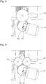
- la
figure 1 représente, de façon schématisée, et en perspective, un centre d'usinage selon l'invention, comportant, au-dessus d'une embase fixe, un premier étage fixe en partie supérieure, comportant des unités d'usinage sur trois de ses quatre stations latérales supérieures dont deux sont visibles, et, entre l'embase et le premier étage, un deuxième étage mobile en rotation autour d'un axe vertical, comportant quatre stations latérales inférieures, ici chacune équipée d'un préhenseur rotatif, ou doublement rotatif; un premier poste d'usinage, et un deuxième poste d'usinage, d'agencement différent, sont visibles sur cette figure ; ce centre d'usinage est dans une position instantanée où une première station supérieure du premier étage surmonte une première station inférieure, et ainsi de suite; au cours du cycle d'usinage, les autres stations inférieures vont passer ensuite, successivement, sous la première station supérieure, et de la même façon les coopérations sont incrémentées d'un pas à chaque rotation du deuxième étage inférieur ; - la
figure 2 représente, de façon similaire à lafigure 1 , et au même instant que lafigure 1 , un détail du premier poste d'usinage où coopèrent cette première station supérieure, laquelle comporte un disque de diamantage à axe vertical, et une tourelle oblique d'usinage à l'outil, et une première station inférieure, avec un préhenseur birotatif combinant un axe B et un axe C qui se croisent sensiblement au niveau de la zone à usiner ; le prisme rectangulaire représente le volume usinable ;
- la
figure 3 représente, de façon schématisée et en vue de dessus, le centre d'usinage de lafigure 1 , et au même instant que lafigure 1 , dans la même position relative du premier étage supérieur et du deuxième étage inférieur ; dans cette configuration particulière et non limitative, le premier étage supérieur ne comporte que trois stations supérieures occupées par des unités d'usinage : la première et la deuxième stations supérieures visibles sur lafigure 1 , et une troisième station supérieure sur la face opposée à la première station, et qui comporte deux barillets obliques d'usinage à l'outil ; la quatrième station supérieure, opposée à la deuxième station, ne comporte pas d'unité d'usinage, ce qui autorise l'insertion d'un manipulateur pour effectuer un contrôle et/ou un échange de pièce dans la broche du préhenseur du deuxième étage inférieur seul visible sous cette quatrième station supérieure ; une zone externe d'alimentation visible en partie droite de la figure permet les échanges de pièces et/ou d'outils avec la zone machine ; - la
figure 4 montre, de façon similaire à lafigure 1 , et au même instant que lafigure 1 , une autre vue, où sont visibles le premier poste, le quatrième poste, et la zone externe d'alimentation ; - la
figure 5 illustre, de façon similaire à lafigure 2 , et au même instant que lafigure 1 , le deuxième poste d'usinage, qui comporte deux unités d'usinage en deuxième station supérieure : une meule, et un support fixe comportant des burins de tournage, agencés pour tourner la pièce maintenue en pince dans une broche portée par le préhenseur de l'étage inférieur, qui est du type birotatif ; - la
figure 6 illustre, de façon similaire à lafigure 2 , mais à un autre instant postérieur à celui de lafigure 1 , un troisième poste d'usinage, qui comporte deux unités d'usinage en troisième station supérieure, chacune constituée par une tourelle d'usinage à l'outil, qui coopère avec un préhenseur inférieur birotatif ; - la
figure 7 est similaire à lafigure 6 , et montre un troisième poste d'usinage, et au même instant que lafigure 1 , et dans une configuration différente de lafigure 6 , où les deux mêmes unités d'usinage en troisième station supérieure, coopèrent avec un autre préhenseur inférieur qui est rotatif et comporte une pince à mâchoires porteuse de la pièce à usiner, qui est ainsi usinable recto-verso ou sur une tranche; - la
figure 8 illustre, de façon similaire à lafigure 2 , un autre centre d'usinage que celui des figures précédentes, ou du moins comportant un équipement différent d'une de ses stations supérieures, avec une meule d'axe horizontal agencée pour coopérer avec un préhenseur de l'étage inférieur, du type birotatif ; - la
figure 9 illustre une variante de lafigure 8 , avec une station supérieure, comportant deux meules d'axe horizontal, chacune agencée pour coopérer avec un préhenseur de l'étage inférieur, du type birotatif ; - la
figure 10 est une vue similaire à lafigure 1 , tournée d'un quart de tour ; - la
figure 11 est un schéma en vue de côté illustrant un centre d'usinage dont les différentes fonctions sont assurées à des niveaux différents, empilés l'un sur l'autre, de façon sensiblement coaxiale : du bas vers le haut, l'embase fixe formant le bâti de la machine, puis une station d'automation pour le contrôle et/ou l'échange de pièces, puis un deuxième étage inférieur, puis un premier étage supérieur, puis un troisième étage supérieur de même type que le deuxième étage inférieur, puis une station de contrôle et/ou changement d'outils et/ou de diamantage de meules, puis un magasin d'outils ; - la
figure 12 est un schéma illustrant l'agencement relatif des cinq axes de travail dans l'espace ; - les
figures 13 à 17 illustrent, pas par pas, le changement de coopération entre les stations de l'étage inférieur qui sont mobiles, avec les stations de l'étage supérieur qui sont fixes ; - la figure 18 est un schéma-blocs représentant certains éléments fonctionnels du centre d'usinage.
- the
figure 1 shows schematically, and in perspective, a machining center according to the invention, comprising, above a fixed base, a first fixed stage in the upper part, comprising machining units on three of its four upper side stations, two of which are visible, and, between the base and the first stage, a second stage movable in rotation about a vertical axis, comprising four lower side stations, each here equipped with a rotary or double rotary gripper ; a first machining station, and a second machining station, of different arrangement, are visible in this figure; this machining center is in an instant position where a first upper station of the first stage surmounts a first lower station, and so on; during the machining cycle, the other lower stations will then pass, successively, under the first upper station, and in the same way the cooperations are incremented by one step at each rotation of the second lower stage; - the
figure 2 represents, similarly to thefigure 1 , and at the same time as thefigure 1 , a detail of the first machining station where this first upper station cooperates, which comprises a diamond disk with vertical axis, and an oblique turret for machining with the tool, and a first lower station, with a birotative gripper combining an axis B and an axis C which substantially intersect at the level of the area to be machined; the rectangular prism represents the machinable volume;
- the
figure 3 shows, schematically and in top view, the machining center of thefigure 1 , and at the same time as thefigure 1 , in the same relative position of the first upper stage and the second lower stage; in this particular and non-limiting configuration, the first upper stage comprises only three upper stations occupied by machining units: the first and the second upper stations visible on thefigure 1 , and a third upper station on the face opposite to the first station, and which comprises two oblique barrels for machining with the tool; the fourth upper station, opposite the second station, does not have a machining unit, which allows the insertion of a manipulator to perform a control and / or a part exchange in the spindle of the second stage gripper lower only visible under this fourth upper station; an external feeding zone visible in the right part of the figure allows the exchange of parts and / or tools with the machine zone; - the
figure 4 shows, similarly to thefigure 1 , and at the same time as thefigure 1 , another view, where the first station, the fourth station, and the external feeding area are visible; - the
figure 5 illustrates, similarly to thefigure 2 , and at the same time as thefigure 1 , the second machining station, which comprises two machining units in the second upper station: a grinding wheel, and a fixed support comprising turning chisels, arranged to turn the workpiece held in clamp in a spindle carried by the gripper of the 'lower stage, which is of the birotative type; - the
figure 6 illustrates, similarly to thefigure 2 , but at another time after that of thefigure 1 , a third machining station, which comprises two machining units in the third upper station, each consisting of a tool machining turret, which cooperates with a lower rotary gripper; - the
figure 7 is similar to thefigure 6 , and shows a third machining station, and at the same time as thefigure 1 , and in a different configuration from thefigure 6 , where the same two machining units in the third upper station, cooperate with another lower gripper which is rotary and comprises a jaw clamp carrying the workpiece, which is thus machinable recto-verso or on a wafer; - the
figure 8 illustrates, similarly to thefigure 2 , another machining center than that of the preceding figures, or at least comprising equipment different from one of its upper stations, with a grinding wheel of horizontal axis arranged to cooperate with a gripper of the lower stage, of the birotative type ; - the
figure 9 illustrates a variant of thefigure 8 , with an upper station, comprising two grinding wheels of horizontal axis, each arranged to cooperate with a gripper of the lower stage, of the birotative type; - the
figure 10 is a view similar to thefigure 1 , quarter turn tour; - the
figure 11 is a diagram in side view illustrating a machining center whose different functions are performed at different levels, stacked one on the other, in a substantially coaxial manner: from bottom to top, the fixed base forming the machine frame, then an automation station for checking and / or exchanging parts, then a second lower stage, then a first upper stage, then a third upper stage of the same type as the second lower stage, then a control station and / or change of tools and / or grinding of wheels, then a tool magazine; - the
figure 12 is a diagram illustrating the relative arrangement of the five axes of work in space; - the
Figures 13 to 17 illustrate, step by step, the change in cooperation between the stations on the lower floor which are mobile, with the stations on the upper floor which are fixed; - Figure 18 is a block diagram showing certain functional elements of the machining center.
L'invention concerne un centre d'usinage 100 pour composants d'horlogerie en moyennes séries.The invention relates to a
Ce centre d'usinage comporte une embase fixe 60, sur laquelle sont superposés, sensiblement coaxialement, plusieurs étages 10.This machining center comprises a
Au moins un de ces étages est mobile par rapport à l'embase fixe 60, comme dans la plupart des machines-transfert.At least one of these stages is movable relative to the
Chaque étage 10 qui est mobile par rapport à l'embase fixe 60 est indexable en position par rapport à cette embase fixe 60, notamment indexable en position angulaire.Each
Chaque étage 10 comporte, sur sa périphérie, une pluralité de stations 50 distinctes, qui sont disposées selon un pas angulaire constant. Par exemple l'étage 10 comporte des facettes, sur lesquelles sont agencées les différentes stations : quatre stations sur un cube ou similaire, six stations sur un prisme de section hexagonale, ou autre. De façon plus particulière, chaque station s'étend de façon sensiblement plane, selon un plan définissant deux axes linéaires. Plus particulièrement encore, ce plan est sensiblement vertical, ou vertical. On connaît aussi des mécanismes en tourelles, apparus sur les premiers centres d'usinage des années 1960 et 1970, qui toutefois limitent les possibilités de course des unités qu'elles portent, tandis qu'une structure à facettes planes autorise pratiquement tous les degrés de liberté, et permet de concevoir, facilement, des moyens d'usinage à quatre, cinq axes, ou davantage. Si dans la pratique on sait réaliser des centres d'usinage comportant six à huit axes, on se heurte très vite à la difficulté de la gestion des collisions, qui doit prendre en compte le mouvement sur chaque axe, et l'encombrement des pièces en cours d'usinage et des outils ; de plus il est délicat d'assurer une lubrification efficace de la zone de coupe.Each
On remarque que, si les stations 50 sont agencées, au niveau de chaque étage avec un pas constant, ce pas n'est pas nécessairement égal d'un étage à l'autre. Il peut notamment être multiple, sous-multiple, ou autre. L'invention est ici illustrée dans le cas particulier et non limitatif de pas angulaires égaux au niveau des différents étages.It is noted that, if the
L'invention est illustrée ici dans le cas non limitatif d'usinages cinq axes, on comprend qu'il n'existe pas de limitation constructive au nombre d'axes, si ce n'est au niveau des faisceaux électriques, hydrauliques et pneumatiques, qui imposent des limitations de fait des courses angulaires et linéaires.The invention is illustrated here in the non-limiting case of five-axis machining, it is understood that there is no constructive limitation to the number of axes, except at the level of the electrical, hydraulic and pneumatic harnesses, which impose de facto limitations on angular and linear strokes.
Ces stations 50 comportent des unités d'usinage 3, et/ou des préhenseurs 4, dont les mouvements sont commandés par des moyens de pilotage 90 que comporte le centre d'usinage 100 pour piloter tous les mouvements et moteurs d'axes, les moteurs de broche, les systèmes de changement d'outil, de diamantage, et similaires, les durées de vie d'outil, les systèmes de mesure d'outil et de pièces usinées, les moyens de mesure d'effort, les systèmes anti-collisions, les moyens de manutention notamment les changeurs de pièces et de palettes éventuels, les moyens de lubrification, et toutes les servitudes classiques d'une machine-outil d'usinage.These
Un préhenseur 4 est agencé pour maintenir au moins un composant à usiner, et/ou à contrôler, pendant son usinage et/ou son contrôle, soit directement, soit par l'intermédiaire d'au moins un posage.A
Le centre d'usinage 100 comporte une pluralité de postes d'usinage 2. Tel que visible sur les
On notera que le terme « usinage » est à interpréter largement, puisqu'il peut comporter des opérations autres que les traditionnelles coupe et abrasion, et en particulier des usinages ou soudages laser, des collages, des sertissages, ou autres.It will be noted that the term "machining" is to be interpreted broadly, since it may include operations other than the traditional cutting and abrasion, and in particular laser machining or welding, bonding, crimping, or the like.
Chaque poste d'usinage 2 est ainsi constitué par une combinaison, temporaire, entre des stations 50, 51, 52, 53, 54, 501, 502, 503, 504, de deux étages 10 adjacents. Le mouvement d'un étage 10 mobile, en particulier une rotation, est ainsi apte à modifier le positionnement relatif des stations en présence, et substitue, au même emplacement géométrique dans l'espace, un nouveau poste d'usinage 2 au précédent.Each
Selon le type de production à effectuer, le mouvement relatif des étages peut permettre, ou bien de substituer à un poste d'usinage 2 selon une composition particulière, un autre poste d'usinage de même composition, ou bien de lui substituer un poste d'usinage avec une autre composition, le poste d'usinage 2 est alors à composition variable : au moins un mouvement relatif entre deux positions d'indexation de deux étages 10 est alors apte à modifier la composition de chacun des postes d'usinage 2 pour obtenir au moins deux compositions distinctes de ces postes d'usinage 2. Naturellement, il est possible d'agencer le centre d'usinage 2 de façon à panacher ces deux modes de composition des postes d'usinage, de façon à avoir, dans un même cycle de production, certains postes d'usinage identiques entre eux, et d'autres qui sont différents.Depending on the type of production to be carried out, the relative movement of the stages can allow, either to replace a
Par « cycle » on entend ici le parcours d'un produit à usiner sur plusieurs postes d'usinage 2 successifs, obtenu par la rotation d'au moins un étage 10 par rapport à l'embase 60. Selon le travail à effectuer, l'usinage complet peut nécessiter un parcours de ce produit sur la totalité des postes d'usinage 2 constituables, ou une partie seulement. Certains postes d'usinage 2 peuvent être dupliqués à l'identique, dans le but d'équilibrer le temps de transit dans chaque position angulaire, avec la durée la plus faible possible.By “cycle” here is meant the path of a product to be machined on several
Bien entendu, le produit à usiner, assemblé sur un posage du préhenseur 4, ou sur le préhenseur 4 lui-même, n'est pas nécessairement unique: il peut s'agir d'une panoplie de composants. Cette panoplie peut comporter plusieurs composants identiques pour la même opération, ou plusieurs composants identiques mais pour des opérations différentes sur le même poste d'usinage comme des usinages recto-verso, ou encore des composants différents, l'objectif étant de rentabiliser la production du centre d'usinage, tout en équilibrant la durée d'usinage sur chaque poste de travail 2. Plus particulièrement, chaque pièce à usiner est chargée/poussée dans un serrage, et le tout sur un tasseau qui s'indexe dans la broche.Of course, the product to be machined, assembled on a setting of the
Chaque poste d'usinage 2 combine d'une part au moins une unité d'usinage 3 d'une station 50 de l'un de ces étages 10 adjacents, et d'autre part au moins un préhenseur 4 d'une autre station 50 de l'autre des étages 10 adjacents.Each
Et chaque mouvement relatif entre deux positions d'indexation de deux étages 10 modifie la composition de chacun des postes d'usinage 2.And each relative movement between two indexing positions of two
Ce centre d'usinage 100 comporte, parmi les étages 10, au moins un premier étage 30 et un deuxième étage 40 qui sont superposés et adjacents, dont au moins l'un des premier étage 30 et deuxième étage 40 est mobile par rapport à l'embase fixe 60. Le premier étage 30 et le deuxième étage 40 sont agencés de façon à ce que, dans toute position relative d'indexation du premier étage 30 par rapport au deuxième étage 40, chaque poste d'usinage 2 constitué dans cette indexation comporte au moins une unité d'usinage 3 appartenant à l'un de ces deux étages 30 et 40 adjacents, et comporte au moins un préhenseur 4 appartenant à l'autre de ces deux étages 30 et 40 adjacents.This
Selon l'invention, chaque préhenseur 4 a au moins un degré de liberté en rotation par rapport à l'étage qui le porte.According to the invention, each
Plus particulièrement, dans une configuration avantageuse, dans chaque étage 10 comportant au moins un préhenseur 4, au moins un préhenseur 4 a au moins deux degrés de liberté en rotation par rapport à l'étage 10 qui le porte. Plus particulièrement encore, dans chaque étage 10 comportant au moins un préhenseur 4, chaque préhenseur 4 a au moins deux degrés de liberté en rotation par rapport à l'étage 10 qui le porte.More particularly, in an advantageous configuration, in each
Dans une configuration particulière du centre d'usinage 100, au moins le premier étage 30 et le deuxième étage 40 sont chacun mobile par rapport à l'embase fixe 60.In a particular configuration of the
Cette configuration permet de réduire le retour à vide en fin de cycle, imposé par les différents faisceaux technique, tel qu'exposé plus haut, et notamment si ces deux étages se meuvent en sens inverse l'un de l'autre.This configuration makes it possible to reduce the return to no load at the end of the cycle, imposed by the various technical beams, as explained above, and in particular if these two stages move in opposite directions to one another.
Naturellement, ce qui est exposé ici de façon simplifiée avec deux étages seulement, un premier étage 30 et le deuxième étage 40, est extrapolable à un nombre d'étages supérieur. On peut, par exemple, imaginer un étage intermédiaire ne comportant que des préhenseurs 4, intercalé entre deux étages comportant des unités d'usinage 3, conçues pour usiner de part et d'autre les pièces que portent les préhenseurs de l'étage intermédiaire. Les seules vraies limitations sont celles dues aux fournitures de fluides techniques, et aux fournitures de moyens propres à l'usinage, en particulier outils et lubrifiants.Naturally, what is explained here in a simplified manner with only two stages, a
Dans un cas particulier avantageux, en particulier pour des usinages en reprise, au moins une station 50 comporte à la fois au moins une unité d'usinage 3 et au moins un préhenseur 4. Et, de préférence, au moins une station d'un étage adjacent et antagoniste comporte également au moins une unité d'usinage 3 et au moins un préhenseur 4, ce qui autorise un déchargement d'une pièce ébauchée, pour l'usinage en reprise de la zone par laquelle elle était maintenue dans son préhenseur initial.In a particular advantageous case, in particular for repeat machining, at least one
Plus particulièrement, dans au moins un étage 10, au moins une unité d'usinage 3 est mobile en position par rapport à l'étage 10 qui la porte. Plus particulièrement encore, dans au moins un étage 10, chaque unité d'usinage 3 est mobile en position par rapport à l'étage 10 qui la porte. Plus particulièrement encore, dans tout étage 10 comportant au moins une unité d'usinage 3, chaque unité d'usinage 3 est mobile en position par rapport à l'étage 10 qui la porte.More particularly, in at least one
Plus particulièrement, dans au moins un étage 10, au moins un préhenseur 4 est mobile en position par rapport à l'étage 10 qui le porte. Plus particulièrement encore, dans au moins un étage 10, chaque préhenseur 4 est mobile en position par rapport à l'étage 10 qui le porte. Plus particulièrement encore, dans tout étage 10 comportant au moins un préhenseur 4, chaque préhenseur 4 est mobile en position par rapport à l'étage 10 qui le porte.More particularly, in at least one
De façon particulière, au moins une station 50 comporte plusieurs unités d'usinage 3, dont les courses se recouvrent, et les moyens de pilotage 90 sont agencés pour piloter chacune d'entre elles de façon à éviter toute collision avec les autres et les outils qu'elles portent. Une de ces unités 3 peut, ainsi, poursuivre un usinage commencé par une autre unité 3 de la même station 50 pendant l'exécution d'un cycle de changement d'outil, ou de mesure d'outil, ou de diamantage, ou autre, de l'unité d'usinage 3 qui a commencé le travail d'usinage ; et celle-ci peut reprendre le travail d'usinage pendant que la deuxième unité bénéficie à son tour d'une assistance technique. Ainsi l'usinage sur la pièce à usiner n'est pas, ou très peu, interrompu pendant la présence du préhenseur portant cette pièce face à cette station 50 qui porte plusieurs unités d'usinage 3.In particular, at least one
Dans une variante, dans une telle station 50 comportant plusieurs unités d'usinage 3 dont les courses se recouvrent, certaines de ces unités d'usinage 3 sont indépendantes les unes des autres, et, plus particulièrement, ont des guidages distincts.In a variant, in such a
Dans une autre variante, dans une telle station 50 comportant plusieurs unités d'usinage 3 dont les courses se recouvrent, plusieurs unités d'usinage 3 utilisent les mêmes guidages.In another variant, in such a
Le centre d'usinage 100 comporte avantageusement, parmi, ou en plus des postes d'usinage 2, au moins une station d'automation 6 pour le chargement ou le déchargement de composants à usiner ou usinés. Plus particulièrement, au moins une telle station d'automation 6 constitue tout ou partie d'un des étages 10. Plus particulièrement encore, au moins une telle station d'automation 6 est une partie, ou la totalité, d'un étage 10 mobile par rapport à l'embase fixe 60.The
Pour revenir aux étages 10 qui sont mobiles par rapport à l'embase fixe 60, les figures illustrent des étages tous coaxiaux et mobiles en rotation, sensiblement autour d'un même axe vertical, par rapport à l'embase fixe 60, ce cas particulier n'empêche nullement d'autres configurations où au moins un des étages est en rotation autour d'un axe horizontal, comme le sont souvent les magasins d'outils de centres d'usinage horizontaux, ce peut être la configuration des servitudes d'usinage ; approvisionnement en pièces, en outils, mesure pièce, mesure outil, diamantage, et autres. Le centre d'usinage 100 peut aussi avoir une structure complexe de type « Rubik's cube » avec des mouvements de rotation croisés.To return to the
Dans une exécution particulière, les moyens de pilotage 90 sont agencés pour piloter les stations 50 de façon à faire passer successivement chaque unité d'usinage 3 et/ou chaque préhenseur 4 devant un point fixe au voisinage d'une embase fixe 60 que comporte le centre d'usinage 100, laquelle peut être l'embase fixe porteuse des étages 10, ou une autre embase disposée latéralement de façon à dégager l'espace autour des zones de travail pour permettre la surveillance par un opérateur.In a particular embodiment, the control means 90 are arranged to control the
Plus particulièrement, quand des opérations de rectification sont à effectuer, le centre d'usinage 100 comporte au moins une station de diamantage 8, qui est agencée pour procéder en temps masqué au diamantage de meules ou d'outils portés par une des unités d'usinage 3. Plus particulièrement, la station de diamantage 8 est distincte des unités d'usinage 3.More particularly, when grinding operations are to be carried out, the
Dans une variante particulière, le centre d'usinage 100 comporte au moins une station d'usinage à l'outil diamant, qui est agencée pour diamanter une pièce maintenue dans un préhenseur 4.In a particular variant, the
Avantageusement, le centre d'usinage 100 comporte au moins une station de changement d'outil 9, qui est agencée pour procéder en temps masqué à l'échange de meules ou d'outils portés par une des unités d'usinage 3. Plus particulièrement, la station de changement d'outil 9 est distincte des unités d'usinage 3. La station de changement d'outil 9 est avantageusement agencée pour coopérer avec un magasin d'outils 80, que comporte le centre d'usinage 100, et qui peut constituer un des étages 10. Plus particulièrement, la station de changement d'outil 9 est un étage 10 mobile par rapport à l'embase fixe 60.Advantageously, the
Dans une configuration particulière, au moins une unité d'usinage 3 comporte au moins un outil fixe 341, et est agencée pour coopérer avec au moins un préhenseur 4 d'un étage adjacent au sien, lequel préhenseur 4 est mobile selon au moins un degré de liberté par rapport à la station 50 qui le porte ; il est ainsi possible de réaliser des opérations de tournage, alésage, tourillonnage, ou similaire.In a particular configuration, at least one
Avantageusement, au moins un préhenseur 4 comporte au moins une broche 401 pour l'entraînement d'un composant à usiner à sa vitesse d'usinage.Advantageously, at least one
Plus particulièrement, au moins un préhenseur 4 comporte au moins une pince 402 pour le maintien avec serrage d'un composant à usiner, pour autoriser son usinage, ou encore son usinage recto-verso quand la pince est à mâchoires comme sur la
Plus particulièrement, au moins une unité d'usinage 3 comporte une pluralité de broches 301 aptes à l'usinage d'un même composant fixé sur un préhenseur 4 avec minimisation du temps de changement d'outil.More particularly, at least one
De façon avantageuse, le centre d'usinage 100 comporte, en plus des postes d'usinage 2, au moins une station de contrôle 11 pour le contrôle géométrique des composants usinés et/ou des outils utilisés. Plus particulièrement, cette station de contrôle 11 constitue un des étages 10. Plus particulièrement encore, cette station de contrôle 11 est un étage 10 mobile par rapport à l'embase fixe 60.Advantageously, the
Les moyens de pilotage 90 sont de préférence agencés pour corriger les trajectoires et/ou les correcteurs dynamiques d'outils, et/ou pour gérer des remplacements d'outils, voire pour stopper le cycle d'usinage, en fonction des informations en provenance de cette station de contrôle 11.The control means 90 are preferably arranged to correct the trajectories and / or the dynamic tool correctors, and / or to manage tool replacements, or even to stop the machining cycle, as a function of the information coming from this
Le centre d'usinage 100 comporte au moins une centrale de lubrification et de filtration apte à filtrer les résidus d'au moins un type d'usinage, notamment de rectification, de diamantage, et de satinage. Dans le cas où des opérations de différentes natures sont à effectuer, les circuits de lubrification et de filtration peuvent être séparés, selon les lubrifiants à utiliser, dans des zones géométriques distinctes : un circuit pour l'usinage à l'outil coupant, un autre circuit pour l'usinage à l'abrasif.The
Plus particulièrement, les étages 10 qui sont mobiles par rapport à l'embase fixe 60 sont mobiles en rotation coaxiale autour d'un axe unique. Plus particulièrement, cet axe unique est vertical.More particularly, the
Les figures illustrent une variante particulière, non limitative, comportant quatre postes d'usinage, combinant chacun deux zones 50, d'un premier étage supérieur 30 statique, et d'un deuxième étage 40 inférieur dynamique.The figures illustrate a particular, non-limiting variant, comprising four machining stations, each combining two
Dans une variante particulière, le centre d'usinage 100 comporte quatre postes: trois réservés à l'usinage, et un quatrième d'usinage conçu pour l'usinage et/ou pour l'automation. Le nombre de postes d'usinage opérationnels dépend du temps de cycle élémentaire, de la décomposition du temps de cycle global, et du temps de manipulation de la pièce.In a particular variant, the
Dans la variante illustrée, chaque poste de travail combine :
- trois degrés de liberté en translation, selon les axes X-Y-Z, plus particulièrement au niveau des unités d'usinage 3 ;
- au moins un degré de liberté en rotation, notamment axe C, ou encore axe B, ou bien deux degrés de liberté en rotation, selon les axes C et B ; plus particulièrement les degrés de liberté en rotation sont au niveau du préhenseur 4.
- three degrees of freedom in translation, along the XYZ axes, more particularly at the level of the
machining units 3; - at least one degree of freedom in rotation, in particular axis C, or even axis B, or else two degrees of freedom in rotation, along axes C and B; more particularly the degrees of freedom in rotation are at the level of the
gripper 4.
Naturellement, en plus de cette configuration minimale, une unité d'usinage 3 peut comporter un ou plusieurs degrés de liberté en rotation, comme un préhenseur 4 peut comporter encore un ou plusieurs degrés de liberté en translation. Certains de ces degrés de liberté supplémentaires, notamment en translation, peuvent être des semi-axes, pour effectuer une palettisation en butée sur des positions extrêmes sans arrêt sur des positions intermédiaires, ou une rotation d'un plateau entre des positions indexées sans arrêt sur des positions intermédiaires.Naturally, in addition to this minimum configuration, a
Sur la machine de transfert ainsi illustrée, tout le deuxième étage 40, comportant les diviseurs s'indexe, de station en station.On the transfer machine thus illustrated, the entire
En raison des liaisons flexibles, la rotation de chaque étage mobile est nécessairement limitée angulairement. De façon pratique, cette limitation angulaire est fixée à une valeur raisonnable, notamment 360°, et, tous les 360° la machine doit, après l'achèvement d'un cycle, se rembobiner sur un tour pour se remettre dans une configuration de départ d'un nouveau cycle.Due to the flexible connections, the rotation of each movable stage is necessarily limited angularly. In practical terms, this angular limitation is fixed at a reasonable value, in particular 360 °, and, every 360 ° the machine must, after the completion of a cycle, rewind on one turn to return to a starting configuration. of a new cycle.
Une telle distribution des axes permet une construction rigide, avec de très courtes boucles de force.Such a distribution of the axes allows a rigid construction, with very short force loops.
Cette compacité autorise des boucles de force courtes, et permet d'avoir des pièces structurelles rigides, conjuguées avec une cinématique facile à protéger.This compactness allows short force loops, and allows to have rigid structural parts, combined with kinematics easy to protect.
La configuration retenue permet différentes possibilités d'outillage, et en particulier, en plus des configurations les plus usuelles :
- une station avec disque de diamantage et avec tourelle d'outils, notamment aptes à de l'usinage à grande vitesse traditionnel;
- station avec peigne de tournage avec burins fixes, emplacements pour broches haute fréquence, et un disque de diamantage.
- a station with diamond disk and with tool turret, in particular suitable for traditional high-speed machining;
- station with turning comb with fixed chisels, locations for high frequency spindles, and a diamond blade.
De manière générale, l'utilisation d'une table rainurée permet un équipement avec différents types d'outils, voire de combinaisons d'outils, tant qu'il n'y a pas de collisions lors de l'usinage.In general, the use of a grooved table allows equipment with different types of tools, or even combinations of tools, as long as there are no collisions during machining.
La possibilité d'équiper la machine avec différents outils/broches/burins sur une machine de transfert de taille moyenne rend le concept intéressant pour différentes applications horlogères.The possibility of equipping the machine with different tools / spindles / chisels on a medium-sized transfer machine makes the concept interesting for different watchmaking applications.
L'emploi d'un nombre de posages pair (notamment quatre) permet un concept d'usinage selon lequel où on travaille les six faces de la pièce en reprise (par exemple deux fois sur un premier posage sur face A, deux fois sur un deuxième posage sur face B), en faisant deux passages à travers la machine.The use of an even number of layings (in particular four) allows a machining concept according to which where the six faces of the piece in recovery are worked (for example twice on a first laying on face A, twice on a second laying on side B), making two passes through the machine.
La machine permet encore une application pour l'usinage d'ébauches horlogères, avec la possibilité de tourner la pièce en utilisation de l'axe C pour usiner les deux faces en un seul serrage, ainsi que l'usinage sur la tranche, et avec la possibilité de masquer le temps de changement d'outil avec le principe double-broche.The machine also allows an application for the machining of horological blanks, with the possibility of turning the workpiece using the C axis to machine the two faces in a single clamping, as well as the machining on the edge, and with the possibility of hiding the tool change time with the double-spindle principle.
L'application à la rectification, dite aussi meulage, peut se faire avec une meule unique, par exemple de diamètre 300mm, ou bien avec plusieurs meules plus petites, par exemple deux meules de diamètre 200mm.The application to grinding, also called grinding, can be done with a single grinding wheel, for example of diameter 300mm, or else with several smaller grinding wheels, for example two grinding wheels of diameter 200mm.
Le centre d'usinage illustré présente bien des avantages en ce qui concerne le process:
- l'usinage avec 5 axes CNC, et plus particulièrement 5 axes continus. De préférence les deux rotations sont centrées dans le centre de la pièce: ainsi il y peu de mouvements de compensation à faire ;
- de nouvelles possibilités sont offertes pour des usinages et en particulier des usinages de décors, notamment de type guillochage ou similaire, sont possibles grâce à l'usinage 5 axes et au changement d'outil, réalisable facilement même pour une tourelle à outils multiples;
- grand nombre d'outils utilisables, et grande diversité des opérations possibles grâce aux trois, voire quatre, stations d'usinage.
- machining with 5 CNC axes, and more particularly 5 continuous axes. Preferably the two rotations are centered in the center of the room: thus there are few compensation movements to be made;
- new possibilities are offered for machining operations and in particular machining of decorations, in particular of guilloche type or similar, are possible thanks to 5-axis machining and tool change, easily achievable even for a turret with multiple tools;
- large number of usable tools, and wide variety of operations possible thanks to the three or even four machining stations.
D'autres avantages concernent le service et l'utilisation de la machine :
- facilité de récupération des matières premières, chute des copeaux ;
- accès aisé pour l'utilisateur-régleur, réglage facilité.
- easy recovery of raw materials, falling chips;
- easy access for the user-adjuster, easy adjustment.
Les avantages en termes de productivité, grâce aux trois stations d'usinage et la station pour la charge/décharge sont d'autant meilleurs que le temps de passage est équilibré sur chacune des stations.The advantages in terms of productivity, thanks to the three machining stations and the station for charging / discharging, are all the better as the passage time is balanced on each of the stations.
D'autres avantages concernent la conception des outillages, facilitée si on standardise des tables X-Z, avec une matrice de taraudages et/ou une matrice de rainurage en té, afin de permettre une grande modularité sur l'outillage.Other advantages relate to the design of the tools, facilitated if we standardize X-Z tables, with a tapping matrix and / or a tee grooving matrix, in order to allow a great modularity on the tooling.
La machine reste suffisamment polyvalente, pour permettre d'autres types d'usinage que ceux pour lesquels la machine est conçue.The machine remains versatile enough to allow other types of machining than those for which the machine is designed.
Le centre d'usinage 100 selon l'invention est plus particulièrement conçu pour des travaux à partir d'un brut, ou en reprise. Toutefois, au moins un étage 10 porteur d'unités d'usinage 3 peut être muni d'un avance-barres, ou bien d'un ravitailleur de mini-barres, de longueur proche de celle de la broche, au niveau d'une de ces unités d'usinage 3, ce qui suppose que l'unité d'usinage correspondante 3 soit fixe. De préférence cet avance-barres est unique, car, s'il est en théorie possible d'implanter alors plusieurs unités d'usinage 3 avec une telle alimentation par avance-barres, l'emprise au sol est alors très fortement augmentée, ce qui réduit un des avantages de cette machine, qui est sa compacité. Plus particulièrement, cet avance-barres est fixé à l'embase 60.The
L'avantage d'un centre d'usinage tel que décrit et illustré est l'usinage complet de composants terminés, sans reprise.The advantage of a machining center as described and illustrated is the complete machining of finished components, without rework.
Dans une variante particulière de mise en oeuvre, cet usinage est réalisé en un seul serrage, avec travail uniquement sur cinq faces.In a particular variant of implementation, this machining is carried out in a single clamping, with work only on five sides.
Dans une autre variante particulière de mise en oeuvre, cet usinage est réalisé avec retournement de pièce, et changement de serrage, pour usinage sur l'ensemble de ce composant, sur toutes ses faces.In another particular variant of implementation, this machining is carried out with part turning, and change of clamping, for machining on the whole of this component, on all its faces.
Le centre d'usinage selon l'invention autorise des temps opératoires très courts. De ce fait le cycle d'alimentation en bruts à usiner et de déchargement des composants usinés est loin d'être négligeable devant les temps d'usinage sur chacun des postes de travail 2, et devant le temps du cycle complet, et cette durée de charge/décharge peut dans certains cas constituer le temps menant du cycle global. On peut estimer les différents temps de cycle élémentaires dans une fourchette de 10 à 15 secondes environ, ce qui incite à augmenter le nombre de composants au niveau de chaque préhenseur, et/ou de faire coopérer une même unité d'usinage 3 avec deux préhenseurs 4 distincts, par exemple au niveau de deux étages 10 distincts, situés de part et d'autre de l'étage comportant cette unité d'usinage, l'un inférieur, et l'autre supérieur.The machining center according to the invention allows very short operating times. As a result, the cycle of supply of crude to be machined and of unloading of the machined components is far from being negligible compared to the machining times on each of the
En somme, l'originalité de cette machine réside dans la combinaison entre :
- le nombre de postes de travail, qui est relativement réduit, quatre dans l'exemple illustré par les figures ;
- la disposition des axes machine, avec une cinématique avantageuse en raison de la proximité des unités d'usinage et des préhenseurs, qui permet de réduire drastiquement les courses à vide ;
- la polyvalence pour la réalisation d'applications horlogères très différentes par simple échange des outillages : diamantage, tournage-fraisage, meulage, et autres.
- the number of work stations, which is relatively small, four in the example illustrated by the figures;
- the arrangement of the machine axes, with an advantageous kinematics due to the proximity of the machining units and the grippers, which makes it possible to drastically reduce the empty strokes;
- versatility for the realization of very different watchmaking applications by simple exchange of tools: diamond dressing, turning-milling, grinding, and others.
L'invention permet l'augmentation des performances dans différentes applications horlogères, tout en permettant de standardiser les équipements de production. De plus, à travers son nombre de postes relativement modeste, cette machine est plus adaptée aux lots de production actuels en horlogerie qu'aux grandes séries d'autrefois.The invention makes it possible to increase performance in different watchmaking applications, while making it possible to standardize production equipment. In addition, thanks to its relatively modest number of stations, this machine is more suited to current watch production batches than to large series of yesteryear.
Claims (35)
Priority Applications (4)
| Application Number | Priority Date | Filing Date | Title |
|---|---|---|---|
| EP18195543.6A EP3626392B1 (en) | 2018-09-19 | 2018-09-19 | Machining centre for timepiece components |
| US16/543,805 US11524381B2 (en) | 2018-09-19 | 2019-08-19 | Machining centre for timepiece components |
| JP2019157717A JP6936285B2 (en) | 2018-09-19 | 2019-08-30 | Machining center for timekeeping parts |
| CN201910885132.XA CN110919372B (en) | 2018-09-19 | 2019-09-19 | Machining center for timepiece components |
Applications Claiming Priority (1)
| Application Number | Priority Date | Filing Date | Title |
|---|---|---|---|
| EP18195543.6A EP3626392B1 (en) | 2018-09-19 | 2018-09-19 | Machining centre for timepiece components |
Publications (2)
| Publication Number | Publication Date |
|---|---|
| EP3626392A1 true EP3626392A1 (en) | 2020-03-25 |
| EP3626392B1 EP3626392B1 (en) | 2021-07-28 |
Family
ID=63642897
Family Applications (1)
| Application Number | Title | Priority Date | Filing Date |
|---|---|---|---|
| EP18195543.6A Active EP3626392B1 (en) | 2018-09-19 | 2018-09-19 | Machining centre for timepiece components |
Country Status (4)
| Country | Link |
|---|---|
| US (1) | US11524381B2 (en) |
| EP (1) | EP3626392B1 (en) |
| JP (1) | JP6936285B2 (en) |
| CN (1) | CN110919372B (en) |
Families Citing this family (3)
| Publication number | Priority date | Publication date | Assignee | Title |
|---|---|---|---|---|
| EP3797733A1 (en) * | 2019-09-24 | 2021-03-31 | DENTSPLY SIRONA Inc. | Method of planning free-form tool paths for simultaneous two-sided machining with kinematic axis coupling |
| IT202100007280A1 (en) * | 2021-03-25 | 2022-09-25 | Dan Di De Antoni S R L | EQUIPMENT FOR SURFACE PROCESSING OF PIECES |
| EP4082718A1 (en) * | 2021-04-26 | 2022-11-02 | ETA SA Manufacture Horlogère Suisse | Timepiece holder |
Citations (5)
| Publication number | Priority date | Publication date | Assignee | Title |
|---|---|---|---|---|
| JPS5682149A (en) * | 1980-11-21 | 1981-07-04 | Hitachi Seiki Co Ltd | Collecting apparatus of waste for machine module |
| EP2306253A1 (en) * | 2008-07-10 | 2011-04-06 | Citizen Machinery Co., Ltd. | Interference check device, interference check method, and machine tool having the interference check device |
| CH706794B1 (en) * | 2013-01-11 | 2014-02-14 | Bumotec Sa | Processing unit for use in manufacturing line for processing of e.g. small sized components in watch-and-clock-making industry, has spindles whose axes are horizontally spaced at distance that is smaller than half of traverse path |
| US20160346888A1 (en) * | 2014-01-23 | 2016-12-01 | Martin Huber | Machining Device for Machine-Assisted Production and Machining of Dental Workpieces |
| WO2017182839A1 (en) * | 2016-04-18 | 2017-10-26 | Metotecna Sagl | Transfer machine with a rotary table |
Family Cites Families (32)
| Publication number | Priority date | Publication date | Assignee | Title |
|---|---|---|---|---|
| US1360175A (en) * | 1917-10-25 | 1920-11-23 | Bullard Machine Tool Co | Multiple-spindle machine-tool |
| US1508974A (en) * | 1921-07-30 | 1924-09-16 | Reading Automatic Machine Comp | Automatic multiple-spindle-machine tool |
| US1804971A (en) * | 1925-05-02 | 1931-05-12 | Bullard Co | Multiple spindle center turning machine |
| US1911303A (en) * | 1930-11-08 | 1933-05-30 | Jr John Wilson Brown | Bossed arm drilling machine |
| US1967689A (en) * | 1930-12-16 | 1934-07-24 | Cincinnati Bickford Tool Co | Cam controlled multispindle machine |
| US2182799A (en) * | 1938-05-28 | 1939-12-12 | Budd Wheel Co | Heat treating machine tool |
| US2358389A (en) * | 1940-08-04 | 1944-09-19 | Carter Carburetor Corp | Indexing type multiple station drilling machine |
| US2628413A (en) * | 1947-05-16 | 1953-02-17 | Baker Bros Inc | Turret control mechanism |
| US3203316A (en) * | 1963-04-30 | 1965-08-31 | Saginaw Machine And Tool Compa | Machine tool construction |
| US3792633A (en) * | 1973-04-02 | 1974-02-19 | V Kogtev | Vertical multispindle continuous lathe |
| US4642861A (en) * | 1983-09-12 | 1987-02-17 | Saginaw Machine Systems, Inc. | Machine tool construction |
| CH671723A5 (en) * | 1988-03-08 | 1989-09-29 | Azypatent Ag | |
| JPH0755417B2 (en) * | 1989-12-21 | 1995-06-14 | 南精工株式会社 | Mold processing machine |
| JP2678838B2 (en) * | 1991-07-24 | 1997-11-19 | オークマ株式会社 | Combined processing NC lathe |
| JPH05147062A (en) | 1991-11-28 | 1993-06-15 | Yamada Seisakusho Co Ltd | Transfer mold device |
| JP3961214B2 (en) | 2000-11-24 | 2007-08-22 | オークマ株式会社 | Combined processing machine |
| DE10153807A1 (en) * | 2001-11-05 | 2003-05-28 | Emag Maschfab Gmbh | machine tool |
| JP2004174627A (en) | 2002-11-25 | 2004-06-24 | Matsushita Refrigeration Industries (S) Pte Ltd | Cutting and grinding method and device for it |
| ATE393418T1 (en) | 2004-01-26 | 2008-05-15 | Nivarox Sa | METHOD OF PRODUCTION OF TIME INDEXES AND APPARATUS FOR IMPLEMENTING IT |
| JP4624030B2 (en) | 2004-08-05 | 2011-02-02 | 株式会社岡本工作機械製作所 | Machine frame of metal machine tool and casting method thereof |
| EP1775050A1 (en) | 2005-10-14 | 2007-04-18 | Eric Bouille | Set of watch cases |
| JP2009297861A (en) * | 2008-06-16 | 2009-12-24 | Makino J Kk | Machining system |
| CN201464830U (en) | 2009-03-26 | 2010-05-12 | 上海大学 | Multifunctional minitype precise horologe machine tool |
| JP5456500B2 (en) | 2010-02-01 | 2014-03-26 | 小島プレス工業株式会社 | Processing equipment |
| JP6059947B2 (en) | 2012-10-24 | 2017-01-11 | Dmg森精機株式会社 | Combined processing machine and processing method |
| DE102014100212B4 (en) | 2013-01-11 | 2018-04-05 | Bumotec Sa | Machining unit with two spindles and production line |
| IN2013MU04099A (en) * | 2013-12-30 | 2015-08-07 | N Kelkar Nitin | |
| JP5799119B2 (en) | 2014-02-07 | 2015-10-21 | 本田技研工業株式会社 | Shaft workpiece processing equipment |
| CN204094461U (en) * | 2014-08-06 | 2015-01-14 | 烟台环球机床装备股份有限公司 | A kind of building-block machine |
| DE102015009017A1 (en) | 2015-07-10 | 2017-01-12 | Liebherr-Verzahntechnik Gmbh | Method for producing a toothed workpiece with a modified surface geometry |
| WO2017054130A1 (en) | 2015-09-29 | 2017-04-06 | Abb Schweiz Ag | Method and system for machining |
| CN107193203B (en) | 2017-04-20 | 2020-01-07 | 浙江卓越电子有限公司 | Automatic drilling and punching machine for electronic watch watchband and using method |
-
2018
- 2018-09-19 EP EP18195543.6A patent/EP3626392B1/en active Active
-
2019
- 2019-08-19 US US16/543,805 patent/US11524381B2/en active Active
- 2019-08-30 JP JP2019157717A patent/JP6936285B2/en active Active
- 2019-09-19 CN CN201910885132.XA patent/CN110919372B/en active Active
Patent Citations (5)
| Publication number | Priority date | Publication date | Assignee | Title |
|---|---|---|---|---|
| JPS5682149A (en) * | 1980-11-21 | 1981-07-04 | Hitachi Seiki Co Ltd | Collecting apparatus of waste for machine module |
| EP2306253A1 (en) * | 2008-07-10 | 2011-04-06 | Citizen Machinery Co., Ltd. | Interference check device, interference check method, and machine tool having the interference check device |
| CH706794B1 (en) * | 2013-01-11 | 2014-02-14 | Bumotec Sa | Processing unit for use in manufacturing line for processing of e.g. small sized components in watch-and-clock-making industry, has spindles whose axes are horizontally spaced at distance that is smaller than half of traverse path |
| US20160346888A1 (en) * | 2014-01-23 | 2016-12-01 | Martin Huber | Machining Device for Machine-Assisted Production and Machining of Dental Workpieces |
| WO2017182839A1 (en) * | 2016-04-18 | 2017-10-26 | Metotecna Sagl | Transfer machine with a rotary table |
Also Published As
| Publication number | Publication date |
|---|---|
| CN110919372A (en) | 2020-03-27 |
| JP6936285B2 (en) | 2021-09-15 |
| CN110919372B (en) | 2021-11-09 |
| EP3626392B1 (en) | 2021-07-28 |
| US11524381B2 (en) | 2022-12-13 |
| US20200086447A1 (en) | 2020-03-19 |
| JP2020044646A (en) | 2020-03-26 |
Similar Documents
| Publication | Publication Date | Title |
|---|---|---|
| EP3626392B1 (en) | Machining centre for timepiece components | |
| JP6652839B2 (en) | Gear or profile grinder and method of operation of the grinder | |
| FR2563454A1 (en) | MULTI-FUNCTION MACHINE-TOOL WITH TWO PINS | |
| EP2033725A1 (en) | Universal automatic device for supplying and unloading parts for a machine tool | |
| CN110099767B (en) | Method for machining workpiece by machine tool and machine tool thereof | |
| EP1314512B1 (en) | Holding unit for the automatic machining of workpieces, and device and procedure incorporating such a device | |
| EP0799104A1 (en) | Machine tool for machining crankshafts for engines with four in-line cylinders, method for operating same, and machining line comprising said machine tool | |
| FR3004371A1 (en) | DOUBLE-PIN TOOL MACHINE-TOOL | |
| EP0032890A1 (en) | Machining centre-type machine tools | |
| FR2495983A1 (en) | DEVICE FOR INVERTING THE CLAMPING OF PARALLEL PLANE PARTS | |
| CN103826797B (en) | Machine tool | |
| FR2983104A1 (en) | DEVICE AND METHOD FOR GRINDING EXTERNALLY BILLED THREAD | |
| CH715355A2 (en) | Machining center for watch components. | |
| FR2641998A1 (en) | PROCESS FOR THE MACHINING OF PARTS USING DIGITAL-CONTROLLED MACHINING CENTERS, AND MACHINING CENTER FOR CARRYING OUT SAID METHOD | |
| FR2702165A1 (en) | Single-point loading / unloading system for a dual ram rotary blind spline broaching machine. | |
| JP2007175852A (en) | Compound nc lathe with inverted main spindle | |
| FR2833198A1 (en) | DEVICE FOR THE TREATMENT OF MECHANICAL SURFACES OF MACHINED PARTS | |
| FR2809649A1 (en) | Transfer machine has several workstations, drive arrangement for stepwise rotation of rotary table in one direction and continuous rotation without stopping in opposite direction | |
| FR2976199A1 (en) | Press arrangement for pressing parts manufactured in production line for manufacturing cars, has presses established in predetermined order, so that each press takes part in manufacturing of different parts | |
| EP0638007A1 (en) | Automatic multi-spindle lathe | |
| FR2612052A1 (en) | Installation for the automated manufacture of shoes | |
| FR2534837A1 (en) | DIVIDER PLATE FOR MAINTAINING A WORKPIECE DURING ITS MACHINING | |
| JP6677366B1 (en) | Work changer, work transfer device, processing device, method for manufacturing ring bearing, method for manufacturing machine, method for manufacturing vehicle | |
| JP5901415B2 (en) | Grinding machine line and grinding machine line production system | |
| FR2806952A1 (en) | Machining center including a gripping and supporting member adapted to firmly hold the workpiece from the top during the machining operation and to facilitate the removal of chips from the machining area |
Legal Events
| Date | Code | Title | Description |
|---|---|---|---|
| PUAI | Public reference made under article 153(3) epc to a published international application that has entered the european phase |
Free format text: ORIGINAL CODE: 0009012 |
|
| STAA | Information on the status of an ep patent application or granted ep patent |
Free format text: STATUS: THE APPLICATION HAS BEEN PUBLISHED |
|
| AK | Designated contracting states |
Kind code of ref document: A1 Designated state(s): AL AT BE BG CH CY CZ DE DK EE ES FI FR GB GR HR HU IE IS IT LI LT LU LV MC MK MT NL NO PL PT RO RS SE SI SK SM TR |
|
| AX | Request for extension of the european patent |
Extension state: BA ME |
|
| STAA | Information on the status of an ep patent application or granted ep patent |
Free format text: STATUS: REQUEST FOR EXAMINATION WAS MADE |
|
| 17P | Request for examination filed |
Effective date: 20200925 |
|
| RBV | Designated contracting states (corrected) |
Designated state(s): AL AT BE BG CH CY CZ DE DK EE ES FI FR GB GR HR HU IE IS IT LI LT LU LV MC MK MT NL NO PL PT RO RS SE SI SK SM TR |
|
| GRAP | Despatch of communication of intention to grant a patent |
Free format text: ORIGINAL CODE: EPIDOSNIGR1 |
|
| STAA | Information on the status of an ep patent application or granted ep patent |
Free format text: STATUS: GRANT OF PATENT IS INTENDED |
|
| RIC1 | Information provided on ipc code assigned before grant |
Ipc: B23Q 39/02 20060101AFI20210212BHEP Ipc: B23Q 39/04 20060101ALI20210212BHEP |
|
| INTG | Intention to grant announced |
Effective date: 20210319 |
|
| GRAS | Grant fee paid |
Free format text: ORIGINAL CODE: EPIDOSNIGR3 |
|
| GRAA | (expected) grant |
Free format text: ORIGINAL CODE: 0009210 |
|
| STAA | Information on the status of an ep patent application or granted ep patent |
Free format text: STATUS: THE PATENT HAS BEEN GRANTED |
|
| AK | Designated contracting states |
Kind code of ref document: B1 Designated state(s): AL AT BE BG CH CY CZ DE DK EE ES FI FR GB GR HR HU IE IS IT LI LT LU LV MC MK MT NL NO PL PT RO RS SE SI SK SM TR |
|
| REG | Reference to a national code |
Ref country code: GB Ref legal event code: FG4D Free format text: NOT ENGLISH |
|
| REG | Reference to a national code |
Ref country code: CH Ref legal event code: EP |
|
| REG | Reference to a national code |
Ref country code: DE Ref legal event code: R096 Ref document number: 602018020702 Country of ref document: DE |
|
| REG | Reference to a national code |
Ref country code: AT Ref legal event code: REF Ref document number: 1414287 Country of ref document: AT Kind code of ref document: T Effective date: 20210815 |
|
| REG | Reference to a national code |
Ref country code: IE Ref legal event code: FG4D Free format text: LANGUAGE OF EP DOCUMENT: FRENCH |
|
| REG | Reference to a national code |
Ref country code: LT Ref legal event code: MG9D |
|
| REG | Reference to a national code |
Ref country code: NL Ref legal event code: MP Effective date: 20210728 |
|
| REG | Reference to a national code |
Ref country code: AT Ref legal event code: MK05 Ref document number: 1414287 Country of ref document: AT Kind code of ref document: T Effective date: 20210728 |
|
| PG25 | Lapsed in a contracting state [announced via postgrant information from national office to epo] |
Ref country code: FI Free format text: LAPSE BECAUSE OF FAILURE TO SUBMIT A TRANSLATION OF THE DESCRIPTION OR TO PAY THE FEE WITHIN THE PRESCRIBED TIME-LIMIT Effective date: 20210728 Ref country code: ES Free format text: LAPSE BECAUSE OF FAILURE TO SUBMIT A TRANSLATION OF THE DESCRIPTION OR TO PAY THE FEE WITHIN THE PRESCRIBED TIME-LIMIT Effective date: 20210728 Ref country code: HR Free format text: LAPSE BECAUSE OF FAILURE TO SUBMIT A TRANSLATION OF THE DESCRIPTION OR TO PAY THE FEE WITHIN THE PRESCRIBED TIME-LIMIT Effective date: 20210728 Ref country code: SE Free format text: LAPSE BECAUSE OF FAILURE TO SUBMIT A TRANSLATION OF THE DESCRIPTION OR TO PAY THE FEE WITHIN THE PRESCRIBED TIME-LIMIT Effective date: 20210728 Ref country code: RS Free format text: LAPSE BECAUSE OF FAILURE TO SUBMIT A TRANSLATION OF THE DESCRIPTION OR TO PAY THE FEE WITHIN THE PRESCRIBED TIME-LIMIT Effective date: 20210728 Ref country code: BG Free format text: LAPSE BECAUSE OF FAILURE TO SUBMIT A TRANSLATION OF THE DESCRIPTION OR TO PAY THE FEE WITHIN THE PRESCRIBED TIME-LIMIT Effective date: 20211028 Ref country code: AT Free format text: LAPSE BECAUSE OF FAILURE TO SUBMIT A TRANSLATION OF THE DESCRIPTION OR TO PAY THE FEE WITHIN THE PRESCRIBED TIME-LIMIT Effective date: 20210728 Ref country code: LT Free format text: LAPSE BECAUSE OF FAILURE TO SUBMIT A TRANSLATION OF THE DESCRIPTION OR TO PAY THE FEE WITHIN THE PRESCRIBED TIME-LIMIT Effective date: 20210728 Ref country code: NL Free format text: LAPSE BECAUSE OF FAILURE TO SUBMIT A TRANSLATION OF THE DESCRIPTION OR TO PAY THE FEE WITHIN THE PRESCRIBED TIME-LIMIT Effective date: 20210728 Ref country code: PT Free format text: LAPSE BECAUSE OF FAILURE TO SUBMIT A TRANSLATION OF THE DESCRIPTION OR TO PAY THE FEE WITHIN THE PRESCRIBED TIME-LIMIT Effective date: 20211129 Ref country code: NO Free format text: LAPSE BECAUSE OF FAILURE TO SUBMIT A TRANSLATION OF THE DESCRIPTION OR TO PAY THE FEE WITHIN THE PRESCRIBED TIME-LIMIT Effective date: 20211028 |
|
| PG25 | Lapsed in a contracting state [announced via postgrant information from national office to epo] |
Ref country code: PL Free format text: LAPSE BECAUSE OF FAILURE TO SUBMIT A TRANSLATION OF THE DESCRIPTION OR TO PAY THE FEE WITHIN THE PRESCRIBED TIME-LIMIT Effective date: 20210728 Ref country code: LV Free format text: LAPSE BECAUSE OF FAILURE TO SUBMIT A TRANSLATION OF THE DESCRIPTION OR TO PAY THE FEE WITHIN THE PRESCRIBED TIME-LIMIT Effective date: 20210728 Ref country code: GR Free format text: LAPSE BECAUSE OF FAILURE TO SUBMIT A TRANSLATION OF THE DESCRIPTION OR TO PAY THE FEE WITHIN THE PRESCRIBED TIME-LIMIT Effective date: 20211029 |
|
| PG25 | Lapsed in a contracting state [announced via postgrant information from national office to epo] |
Ref country code: DK Free format text: LAPSE BECAUSE OF FAILURE TO SUBMIT A TRANSLATION OF THE DESCRIPTION OR TO PAY THE FEE WITHIN THE PRESCRIBED TIME-LIMIT Effective date: 20210728 |
|
| REG | Reference to a national code |
Ref country code: DE Ref legal event code: R097 Ref document number: 602018020702 Country of ref document: DE |
|
| REG | Reference to a national code |
Ref country code: BE Ref legal event code: MM Effective date: 20210930 |
|
| PG25 | Lapsed in a contracting state [announced via postgrant information from national office to epo] |
Ref country code: SM Free format text: LAPSE BECAUSE OF FAILURE TO SUBMIT A TRANSLATION OF THE DESCRIPTION OR TO PAY THE FEE WITHIN THE PRESCRIBED TIME-LIMIT Effective date: 20210728 Ref country code: SK Free format text: LAPSE BECAUSE OF FAILURE TO SUBMIT A TRANSLATION OF THE DESCRIPTION OR TO PAY THE FEE WITHIN THE PRESCRIBED TIME-LIMIT Effective date: 20210728 Ref country code: RO Free format text: LAPSE BECAUSE OF FAILURE TO SUBMIT A TRANSLATION OF THE DESCRIPTION OR TO PAY THE FEE WITHIN THE PRESCRIBED TIME-LIMIT Effective date: 20210728 Ref country code: MC Free format text: LAPSE BECAUSE OF FAILURE TO SUBMIT A TRANSLATION OF THE DESCRIPTION OR TO PAY THE FEE WITHIN THE PRESCRIBED TIME-LIMIT Effective date: 20210728 Ref country code: EE Free format text: LAPSE BECAUSE OF FAILURE TO SUBMIT A TRANSLATION OF THE DESCRIPTION OR TO PAY THE FEE WITHIN THE PRESCRIBED TIME-LIMIT Effective date: 20210728 Ref country code: CZ Free format text: LAPSE BECAUSE OF FAILURE TO SUBMIT A TRANSLATION OF THE DESCRIPTION OR TO PAY THE FEE WITHIN THE PRESCRIBED TIME-LIMIT Effective date: 20210728 Ref country code: AL Free format text: LAPSE BECAUSE OF FAILURE TO SUBMIT A TRANSLATION OF THE DESCRIPTION OR TO PAY THE FEE WITHIN THE PRESCRIBED TIME-LIMIT Effective date: 20210728 |
|
| PLBE | No opposition filed within time limit |
Free format text: ORIGINAL CODE: 0009261 |
|
| STAA | Information on the status of an ep patent application or granted ep patent |
Free format text: STATUS: NO OPPOSITION FILED WITHIN TIME LIMIT |
|
| 26N | No opposition filed |
Effective date: 20220429 |
|
| PG25 | Lapsed in a contracting state [announced via postgrant information from national office to epo] |
Ref country code: LU Free format text: LAPSE BECAUSE OF NON-PAYMENT OF DUE FEES Effective date: 20210919 Ref country code: IT Free format text: LAPSE BECAUSE OF FAILURE TO SUBMIT A TRANSLATION OF THE DESCRIPTION OR TO PAY THE FEE WITHIN THE PRESCRIBED TIME-LIMIT Effective date: 20210728 Ref country code: IE Free format text: LAPSE BECAUSE OF NON-PAYMENT OF DUE FEES Effective date: 20210919 Ref country code: BE Free format text: LAPSE BECAUSE OF NON-PAYMENT OF DUE FEES Effective date: 20210930 |
|
| PG25 | Lapsed in a contracting state [announced via postgrant information from national office to epo] |
Ref country code: CY Free format text: LAPSE BECAUSE OF FAILURE TO SUBMIT A TRANSLATION OF THE DESCRIPTION OR TO PAY THE FEE WITHIN THE PRESCRIBED TIME-LIMIT Effective date: 20210728 |
|
| PG25 | Lapsed in a contracting state [announced via postgrant information from national office to epo] |
Ref country code: HU Free format text: LAPSE BECAUSE OF FAILURE TO SUBMIT A TRANSLATION OF THE DESCRIPTION OR TO PAY THE FEE WITHIN THE PRESCRIBED TIME-LIMIT; INVALID AB INITIO Effective date: 20180919 |
|
| P01 | Opt-out of the competence of the unified patent court (upc) registered |
Effective date: 20230701 |
|
| PGFP | Annual fee paid to national office [announced via postgrant information from national office to epo] |
Ref country code: GB Payment date: 20230823 Year of fee payment: 6 |
|
| PGFP | Annual fee paid to national office [announced via postgrant information from national office to epo] |
Ref country code: FR Payment date: 20230822 Year of fee payment: 6 Ref country code: DE Payment date: 20230822 Year of fee payment: 6 |
|
| PGFP | Annual fee paid to national office [announced via postgrant information from national office to epo] |
Ref country code: CH Payment date: 20231001 Year of fee payment: 6 |
|
| PG25 | Lapsed in a contracting state [announced via postgrant information from national office to epo] |
Ref country code: MK Free format text: LAPSE BECAUSE OF FAILURE TO SUBMIT A TRANSLATION OF THE DESCRIPTION OR TO PAY THE FEE WITHIN THE PRESCRIBED TIME-LIMIT Effective date: 20210728 |