EP3624909B1 - Vorrichtung zum biegen von schlittschuhkufen - Google Patents
Vorrichtung zum biegen von schlittschuhkufen Download PDFInfo
- Publication number
- EP3624909B1 EP3624909B1 EP17857578.3A EP17857578A EP3624909B1 EP 3624909 B1 EP3624909 B1 EP 3624909B1 EP 17857578 A EP17857578 A EP 17857578A EP 3624909 B1 EP3624909 B1 EP 3624909B1
- Authority
- EP
- European Patent Office
- Prior art keywords
- lever arm
- blade
- bending apparatus
- main body
- skate
- Prior art date
- Legal status (The legal status is an assumption and is not a legal conclusion. Google has not performed a legal analysis and makes no representation as to the accuracy of the status listed.)
- Active
Links
Images






Classifications
-
- A—HUMAN NECESSITIES
- A63—SPORTS; GAMES; AMUSEMENTS
- A63C—SKATES; SKIS; ROLLER SKATES; DESIGN OR LAYOUT OF COURTS, RINKS OR THE LIKE
- A63C1/00—Skates
- A63C1/22—Skates with special foot-plates of the boot
- A63C1/28—Pivotally-mounted plates
-
- A—HUMAN NECESSITIES
- A63—SPORTS; GAMES; AMUSEMENTS
- A63C—SKATES; SKIS; ROLLER SKATES; DESIGN OR LAYOUT OF COURTS, RINKS OR THE LIKE
- A63C1/00—Skates
- A63C1/30—Skates with special blades
-
- A—HUMAN NECESSITIES
- A63—SPORTS; GAMES; AMUSEMENTS
- A63C—SKATES; SKIS; ROLLER SKATES; DESIGN OR LAYOUT OF COURTS, RINKS OR THE LIKE
- A63C1/00—Skates
- A63C1/30—Skates with special blades
- A63C1/32—Special constructions of the simple blade
-
- A—HUMAN NECESSITIES
- A63—SPORTS; GAMES; AMUSEMENTS
- A63C—SKATES; SKIS; ROLLER SKATES; DESIGN OR LAYOUT OF COURTS, RINKS OR THE LIKE
- A63C1/00—Skates
- A63C1/38—Skates of the tubular type
-
- A—HUMAN NECESSITIES
- A63—SPORTS; GAMES; AMUSEMENTS
- A63C—SKATES; SKIS; ROLLER SKATES; DESIGN OR LAYOUT OF COURTS, RINKS OR THE LIKE
- A63C1/00—Skates
- A63C1/40—Skates manufactured of one piece of material
-
- B—PERFORMING OPERATIONS; TRANSPORTING
- B21—MECHANICAL METAL-WORKING WITHOUT ESSENTIALLY REMOVING MATERIAL; PUNCHING METAL
- B21D—WORKING OR PROCESSING OF SHEET METAL OR METAL TUBES, RODS OR PROFILES WITHOUT ESSENTIALLY REMOVING MATERIAL; PUNCHING METAL
- B21D11/00—Bending not restricted to forms of material mentioned in only one of groups B21D5/00, B21D7/00, B21D9/00; Bending not provided for in groups B21D5/00 - B21D9/00; Twisting
- B21D11/10—Bending specially adapted to produce specific articles, e.g. leaf springs
-
- B—PERFORMING OPERATIONS; TRANSPORTING
- B21—MECHANICAL METAL-WORKING WITHOUT ESSENTIALLY REMOVING MATERIAL; PUNCHING METAL
- B21D—WORKING OR PROCESSING OF SHEET METAL OR METAL TUBES, RODS OR PROFILES WITHOUT ESSENTIALLY REMOVING MATERIAL; PUNCHING METAL
- B21D7/00—Bending rods, profiles, or tubes
- B21D7/06—Bending rods, profiles, or tubes in press brakes or between rams and anvils or abutments; Pliers with forming dies
Definitions
- the invention discussed herein relates to the general field of ice skating accessories and describes a skate blade bending device.
- the most popular long track blades are designed to be mounted in a fixed position in the forefoot of the blade on a hinged arm (34) that is not fixed to the heel of the boot as shown in Fig. 2A , commonly referred to as a "clap skate” named after the clapping sound that occurs when the hinge closes while skating.
- Fig. 2B illustrates the movement of the clap arm. This design allows for longer contact with the ice and more speed to be generated by the skater.
- the hinged clap arm design on the long track skate is not allowed to be used on a short track skate under regulation by the International Skating Union, the governing body for the sport.
- Speed skate racing is generally performed with turns only in the counter-clockwise direction.
- skate boots and blades are typically configured to take advantage of the counter-clockwise turns.
- Blades are mounted on boots with an offset to the left, and some blades are positioned to the left in their support structure.
- the blade runner surface is also generally adjusted with a radius or "rocker" that complements the dimensions of the skating rink and the experience level of the skater.
- the radius applied to a beginning skater is normally a single radius, whereas expert level skaters might use a complex curve made of multiple radii varying over the length of the blade surface, also referred to as a compound radius.
- the chosen rocker is more curved at the heel and toe areas of the blade, and flatter toward the center of the blade. The center section of the blade tends to be more curved than the turn radius of the racing course.
- the blades of expert skaters can be also bent to the left to take advantage of skating only in a counter-clockwise direction.
- the bend applied to the blades can be varied according to the radius to increase the contact area of the blade with the surface of the ice, thereby increasing grip as well as allowing the skater to turn more sharply as they apply weight to that section of the blade.
- skate blades historically was done with a mallet, vise, or similar tool until the blade "looked right" or "felt right.”
- the bending process was usually applied to the blade's tube, rather than the blade runner because the blade runner is more delicate and the tube tends to retain the applied curve better.
- the toe of the blade may be bent so the blade turns more sharply when a skater's weight moves forward.
- the heel of the blade may be bent so the blade turns more sharply when the skater's weight moves back.
- the entire blade can be bent in a smooth arc for increased ice contact and stability, or it may have variable curvature to allow the skater to increase or decrease their turning efficiency depending on the portion of blade they apply pressure to. There was little predictability in this process when performed with mallets and vices, and as a result, skaters were often hesitant to skate on blades bent in this manner.
- the Pennington Blade Bender brought with it a more predictable method of applying the bend to a blade. It allowed the user to apply pressure to a lever arm and flex a portion of the blade between two anvil-like surfaces.
- the anvils were permanently mounted in a sliding track and could be adjusted for width to increase or decrease the size of the area being bent.
- Attached to the lever-arm, mounted above the anvils, was a round disk with a radius on the edge, which is like the round surface of the blades tube holder. When the lever was pushed down, the presser disc was pressed against the blade's tube, and a bend in that section of the blade resulted. The more pressure that was applied to the lever arm, the more bend was applied to the blade.
- the benefits of the Pennington bender included easier repeatability of bending operations, more consistent bending results, the device was portable, and the device was relatively inexpensive.
- the Pennington design which is still in use today, has a main structure which is made of bolted together parts which flex and wear over time because they do not have sufficient torsional rigidity to support the pressure loads applied to the fixture when in use. This results in the device prematurely degrading and becoming unreliable and difficult to use.
- the shape of the main structure also results in easy contact of the blade runner surface against the frame potentially damaging the blades edge.
- the shape of the anvils is angular with an area containing a very small radius in the center which the blade tube sits in. When bending a blade beyond the radius of the anvil, the blade's tube contacts the edge of the anvil and the tube is kinked which weakens the strength of the tube and is aesthetically unsightly.
- the mounting system for the anvils makes adjusting the location of the anvils difficult and does not allow for the use of alternate shaped anvils to accommodate the different tube shapes that are in use on current skate blades, or future skate blades. Additionally, the most current embodiment of the Pennington Bender has a longer lever arm that results in instability when used, in that it causes the bender to tip on the longitudinal plane of the main structure, making the intended use of the bender difficult.
- the Zandstra Blade Bender was not designed for use on short track type blades.
- the anvil mounting design makes it easier to adjust the anvils, but the anvils cannot be replaced with alternate shapes, and the shape of the anvil is flat since it was designed specifically to work on the blade runner and not the tube.
- the flat design could result in blade damage if too much force was applied to the lever arm.
- Mr. Michel Beaudoin discussed a new skate bending device in PCT Application number PCT/CA02/00974 .
- Mr. Beaudoin's invention was a significant departure from the Pennington Blade Bender and the Zandstra Blade Bender in that it was more complex.
- Mr. Beaudoin's design used roller wheels, knobs, levers, hand cranks, and dial indicators, and made it possible to apply smooth bends across the entire length of the blade in one operation. It was also possible to adjust the bend in specific areas of the blade with the Zandstra design. However, in addition to being more complex, the design was heavier, and costlier than other available benders.
- the design did not allow for bending long track blades because there was no clearance on the roller wheels for the long track blade's hinge mount mechanism that holds the boot mounting arm. Additionally, the design removed the user's ability to feel how the blade flexed as pressure was applied. Since blades vary from manufacturer to manufacturer, and even from batch to batch by the same manufacturer, merely having a dial indicator number for identifying what the device is doing to the blade is, counter-intuitively, insufficient for providing uniformity in outcome in this scenario. To illustrate this, the Pennington Bender has a facility to install a dial indicator to measure pressure, but very few users ever did so for the reasons mentioned. Furthermore, Mr. Beaudoin's design requires that the blade be separated from the boot to be passed through his machine.
- a skate blade having a generally elongated configuration, is defined as a blade runner which provides a contacting section for contacting a gliding surface such as ice, and a blade attachment section for attaching the blade to a skate boot.
- the skate blade also defines a blade longitudinal axis, a blade first side surface, and a blade second side surface.
- the bending apparatus is comprised of: a one-piece frame; a pressure exerting means attached to the frame for exerting bending pressure on a skate blade in a pressure direction generally perpendicular to the blades longitudinal axis at a predetermined pressure location; an integrated shape within the frame design which allows the user to more precisely apply force to the pressure exerting means, and a blade securing means attached to the frame for locally securing the skate blade so as to allow the bending pressure exerted by the pressure exerting means to bend the skate blade about the pressure location.
- the blade securing means is a pair of longitudinally adjustable restraining locations which are positioned opposite the pressure location in a vertical orientation.
- the securing means can be adjusted to specify the area upon which pressure will be applied to the skate blade's longitudinal plane.
- the securing means locally restrains blade movement of the skate blade, generally parallel to the pressure direction, allowing for the skate blade to deflect in a perpendicular direction between the blade restraint locations.
- the result of the securing action and blade deflection allows for the bending of the skate blade.
- the securing means allows for movement of the skate blade along the blade attachment surface during the application of pressure allowing for precise application of bending pressure without damage to the blade attachment surface.
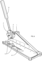
- the skate blade bending apparatus is shown in an exploded view in FIG. 4 .
- a main body bearing (rear) (2) and a main body bearing (front) (4) are inserted into a main body (1).
- a main assembly pin (3) is inserted into the main body (1).
- a lever arm mount washer (5) is placed onto the main assembly pin (3).
- a dowel pin (7) is inserted into dowel pin hole (17) in a lever arm mount (6).
- a lever arm (12) is installed into a lever arm handle (13) to form an adjustable lever arm assembly (14).
- the lever arm mount (6) is installed onto the main assembly pin (3) such that lever arm hole (20) is aligned with main assembly pin alignment slot (21).
- the adjustable lever arm assembly (14) is installed into the lever arm mount (6) at lever arm hole (20) until it is tightened against main assembly pin alignment slot (21).
- a presser wheel bearing (9) is installed into a presser wheel (8) to form a presser wheel assembly (10).
- Attach the presser wheel assembly (10) to the lever arm mount (6) by inserting a presser wheel assembly pin (11) through the presser wheel bearing (9) and into presser wheel assembly pin hole (19).
- a line of graduation marks (29) is placed adjacent to anvil track (23) to assist with placement and use of the anvils (15).
- a recessed area (27) on the face of the main body aids in preventing contact between the skate blade runner surface and the main body (1).
- the main body (1) of this embodiment be made of aluminum and Computerized Numerical Control machined from a solid block of material, but other materials and methods are also suitable including, but not limited, to alloys, plastics, composites such as carbon fiber, etc.
- bearings (2), (4), and (9) be made of bronze and solid in design, but other materials are suitable as are other types of bearings including ball, needle, etc.
- lever arm (12), the lever arm mount (6), the dowel pin (7), the presser wheel assembly pin (11), and the main assembly pin (3) be made of steel, but other materials also suitable.
- lever arm handle (13) be made of plastic, but other materials are also suitable.
- lever arm assembly (14) can be adjusted to increase or decrease the effective length of the lever arm by using threaded component parts (12) and (13), but other mechanisms such as set screws, spring loaded detent assemblies, servo motors, etc. are also possible.
- presser wheel assembly (10) be operated manually with the lever arm assembly (14), but other mechanically controlled means of delivering force through the presser wheel assembly (10) would also be suitable, including but not limited to, pneumatic, hydraulic, and screw driven mechanisms.
- anvil(s) (15, 15a, 15b) be made of heat treated steel, but other materials are also suitable.
- main body feet (16) be made of rubber and affixed with threaded fasteners, but other materials and fastening mechanisms are suitable.
- the recessed area (27) include a thin protective rubber coating to further protect against damage to the blade runner surface, but other materials such as PTFE, urethane, silicone, etc. are also suitable. Further, the addition of this coating can be considered optional but beneficial.
- the main body structure comprises a generally concave area horizontally adjacent to the means for exerting downward force and the securement structure to prevent contact and damage to the skate blade.
- the graduation marks (29) be etched into the aluminum surface of main body (1), but these marks can also be included by CNC machining, screen printing, surface labeling, etc., or other suitable means. Further, the graduation marks are purely for making the procedure a repeatable process and they can be designated by letters, numerals, or other symbols as appropriate.
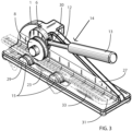
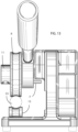
- the blade bending apparatus achieves its results in the following ways ( FIGS. 3 , 14-16 ):
- the user first locates two positionable anvils (15) along the anvil rail track (23) with each anvil (15) placed on opposing sides of the centerline of presser wheel (8).
- Graduation marks (29), are used to choose repeatable positions for placement of the anvils (15) to achieve the user's desired result.
- a skate blade can be inserted between the anvils (15) and the presser wheel (8) orientated so that the blade runner is facing recessed area (27), and the blade tube (33) is positioned atop the anvils (15) with the area of the blade to be bent centered under the presser wheel (8).
- the user of the blade bending apparatus applies a bending force to a skate blade tube in a horizontal plane by the user applying pressure to the adjustable lever arm assembly (14), which in turn presses the presser wheel assembly (10) against the skate blade tube (33) in the user specified area.
- the two positionable anvils (15) are placed on opposite sides of the center line of the presser wheel (8) in user determined locations.
- the two positionable anvils (15) support the underside of the skate blade tube (33) as well as preventing horizontal movement during the application of pressure. The further apart the two positionable anvils (15) are placed, the broader the area of the skate blade tube is bent. The closer together the two positionable anvils (15) are placed, the narrower an area of the skate blade tube is bent.
- the user can increase or decrease the adjustable lever arm assembly (14) length to adjust the amount of force generated by the lever arm.
- the adjustable lever arm assembly (14) length is adjusted by placing a suitable tool on tool fitting area (30) on the lever arm (12), and then turning lever handle (13). Turning lever handle (13) clockwise will decrease the length of the assembly. Turning lever handle (13) counter-clockwise will increase the length of the assembly ( FIG 7 ).
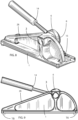
- a hand grip rail (28) on the top back side of main body (1), as shown in FIGS. 8, 9 , and 10 .
- the hand grip rail allows for additional feedback to the user with respect to the amount of force being applied to the lever arm.
- the hand grip rail (28) can also be used to carry the blade bender apparatus.
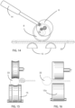
- Anvils (15) and presser wheel (8) with a concave profile may be exchanged with profiles that are smooth and flat (15a) as shown in FIG. 16 to allow bending operations on the flat blade runner attachment surface to allow easier bending of the skate blade across the entire length of the blade if desired.
- FIG. 16-18 If a user has blades that do not properly fit in the radius of the anvils (15) and presser wheel (8), these parts can be easily exchanged for alternate components with different radii, half radius, flat shapes, etc. as shown in FIG. 16-18 .
- the examples shown in FIG. 17 (15a) and FIG. 18 (15b) are only a subset of possible shapes and should in no way be viewed as limiting.
- the anvils (15) and presser wheel (8) can be surfaced with a different material, for example, rubber, plastic, etc. so as not to mar or damage the skate blades surface finish.
- the anvils (15) and the presser wheel (8) can be of diverse sizes and shapes. Varied materials, sizes, and interconnections can be used for all components.
- the blade bending apparatus of the various embodiments can be used to provide an easy, precise, convenient, and repeatable method to bend skate blades of various shapes and configurations, over as much, or as little, of the blades length as the user desires, that does not damage the skate blades, that is easily adjusted for bending operation and user configuration preferences, that is easily transported, that can be easily adapted to new blade designs without requiring replacement of the apparatus, and that has an attractive appearance.
- the main body can have other shapes, such as circular, trapezoidal, triangular, etc.; the lever arm mount and anvils can likewise have other shapes, etc.
- the scope of the embodiments should be determined by the appended claims rather than by the examples given.
- the present invention may be manufactured and used in industry, with a primary purpose of being used in the ice skating industry.
Landscapes
- Engineering & Computer Science (AREA)
- Mechanical Engineering (AREA)
- Footwear And Its Accessory, Manufacturing Method And Apparatuses (AREA)
Claims (10)
- Biegevorrichtung (35) zum Biegen einer Schlittschuhkufe, wobei die Schlittschuhkufe eine verlängerte schienenartige Stütze und eine Kufenläufer-Komponente umfasst, wobei die Biegevorrichtung Folgendes umfasst:eine einteilige Hauptkörperstruktur (1) mit einer Oberseite, einer Unterseite, einer Vorderseite und einer Rückseite mit einer Handgriffschiene (28), die an einer oberen Rückseite der Hauptkörperstruktur (1) angeordnet ist;eine variabel positionierbare Befestigungsstruktur (10, 15) entlang der Vorderseite der Hauptkörperstruktur (1), um die Schlittschuhkufe selektiv an der Hauptkörperstruktur (1) so zu befestigen, dass eine Längsachse der Schlittschuhkufe im Wesentlichen parallel zu der Unterseite verläuft, wobei die Befestigungsstruktur (10, 15) wiederholt relativ zu der Hauptkörperstruktur (1) positionierbar ist; undein Mittel zum Ausüben von Abwärtskraft (8), das an der Hauptkörperstruktur (1) angebracht ist, sodass Biegedruck auf die Schlittschuhkufe in einer Kraftrichtung ausgeübt wird, die im Allgemeinen senkrecht zu der Längsachse der Kufe an einer vorbestimmten Position ist,wobei die Handgriffschiene (28) eine Struktur zum Bereitstellen von taktilem Benutzer-Feedback über den durch das Kraftausübungsmittel erzeugten Biegedruck und einen Griff zum bequemen Transportieren der Vorrichtung bereitstellt,wobei das Mittel zum Ausüben von Abwärtskraft (8) eine Hebelarmbaugruppe (14) mit einer Drückerbaugruppe ist, wobei die Drückerbaugruppe auch als mindestens ein Teil der Befestigungsstruktur (10, 15) dient,wobei die Biegevorrichtung dadurch gekennzeichnet ist, dass die Hebelarmbaugruppe (14) eine einstellbare Hebelarmlänge zum Einstellen der von der Hebelarmbaugruppe (14) erzeugten Kraftmenge aufweist.
- Biegevorrichtung nach Anspruch 1, wobei die Hebelarmlänge durch Platzieren einer Einstellanordnung auf einem Anpassungsbereich (30) auf dem Hebelarm (12) der Hebelarmbaugruppe (14) einstellbar ist, wobei die Einstellanordnung so konfiguriert ist, dass ein Drehen des Hebelarms (12) der Hebelarmbaugruppe (14) zu einer Einstellung der Hebelarmlänge führt.
- Biegevorrichtung nach Anspruch 1, wobei die Hebelarmbaugruppe (14) einen Hebelarm (12) umfassend einen weiblichen Schlitz und einen Hebelarmgriff (13) umfassend einen passenden männlichen Steg und eine Stellschraube aufweist, wodurch dem Hebelarmgriff (13) ermöglicht wird, entlang des Hebelarms (12) auf die gewünschte Länge zu gleiten und dann mit der Stellschraube in Position arretiert zu werden.
- Biegevorrichtung nach Anspruch 1, wobei die Hebelarmbaugruppe (14) einen Hebelarm (12) umfassend eine weibliche Rastvertiefung und einen Hebelarmgriff (13) umfassend einen passenden männlichen Rastfeder- und Kugelmechanismus aufweist, wodurch dem Griff (13) ermöglicht wird, in verschiedene Positionen mit unterschiedlichen Hebelarmlängen bewegt und durch den Feder- und Kugelmechanismus in Position arretiert zu werden.
- Biegevorrichtung nach Anspruch 1, wobei die Hebelarmbaugruppe (14) einen Hebelarm (12) und einen Hebelarmgriff (13) aufweist, die eine Zahnstangenbaugruppe und einen batteriebetriebenen Mikroservomotor aufweisen, der dazu konfiguriert ist, den Griff entlang der Hebelarmlänge in die gewünschte Benutzerposition hinein und aus dieser heraus zu bewegen.
- Biegevorrichtung nach Anspruch 1, wobei die Hauptkörperstruktur (1) ferner einen im Allgemeinen konkaven Bereich umfasst, der horizontal an das Mittel zum Ausüben von Abwärtskraft (8) und die Befestigungsstruktur (10, 15) angrenzt, um Kontakt und Beschädigung der Schlittschuhkufe zu verhindern.
- Biegevorrichtung nach Anspruch 1, wobei die Befestigungsstruktur (10, 15) ein Paar Rückhalteambosse (15) umfasst, die an einer benutzerdefinierten Position und in einem benutzerdefinierten Breitenabstand unter dem Mittel zum Ausüben von Abwärtskraft (8) und entlang der Längsachse der Schlittschuhkufe positioniert werden können.
- Biegevorrichtung nach Anspruch 7, wobei das Paar Ambosse (15) und das Mittel zum Ausüben von Abwärtskraft (8) leicht austauschbar sind, mit optimal angepassten geformten Komponententeilen, um Anpassungsfähigkeit für unterschiedlich geformte Kufen bereitzustellen.
- Biegevorrichtung nach Anspruch 7, ferner umfassend eine Positionierskala, wobei die Ambosse (15) in der Lage sind, präzise an wiederholbaren Positionen entlang der Längsachse der Kufe positioniert zu werden.
- Biegevorrichtung nach Anspruch 7, wobei die Befestigungsstruktur (10, 15) abnehmbar an der Hauptkörperstruktur angebracht ist.
Applications Claiming Priority (2)
| Application Number | Priority Date | Filing Date | Title |
|---|---|---|---|
| US201662401597P | 2016-09-29 | 2016-09-29 | |
| PCT/US2017/054577 WO2018064616A1 (en) | 2016-09-29 | 2017-09-29 | Ice skate blade bending apparatus |
Publications (3)
| Publication Number | Publication Date |
|---|---|
| EP3624909A1 EP3624909A1 (de) | 2020-03-25 |
| EP3624909A4 EP3624909A4 (de) | 2021-03-03 |
| EP3624909B1 true EP3624909B1 (de) | 2025-04-16 |
Family
ID=61763615
Family Applications (1)
| Application Number | Title | Priority Date | Filing Date |
|---|---|---|---|
| EP17857578.3A Active EP3624909B1 (de) | 2016-09-29 | 2017-09-29 | Vorrichtung zum biegen von schlittschuhkufen |
Country Status (6)
| Country | Link |
|---|---|
| US (1) | US11033945B2 (de) |
| EP (1) | EP3624909B1 (de) |
| KR (1) | KR102420802B1 (de) |
| CN (1) | CN109996588B (de) |
| CA (1) | CA3038980C (de) |
| WO (1) | WO2018064616A1 (de) |
Families Citing this family (4)
| Publication number | Priority date | Publication date | Assignee | Title |
|---|---|---|---|---|
| USD872779S1 (en) * | 2017-09-29 | 2020-01-14 | Mayflower Inductries, LLC | Ice skate blade bending apparatus |
| NL2021395B1 (en) * | 2018-07-25 | 2020-01-31 | Schaatsenfabriek Viking B V | Clap skate |
| FR3107191B1 (fr) * | 2020-02-14 | 2023-11-03 | Decathlon Sa | Moyen de verrouillage pour lame de patin à glace |
| CN120828097B (zh) * | 2025-09-18 | 2025-12-09 | 山西二建集团有限公司 | 一种钢筋掰弯装置 |
Family Cites Families (11)
| Publication number | Priority date | Publication date | Assignee | Title |
|---|---|---|---|---|
| US3420080A (en) * | 1966-06-23 | 1969-01-07 | Applied Science Lab Inc | Coiling device |
| US3822578A (en) * | 1973-01-24 | 1974-07-09 | Breton L Le | Pipe bending devices |
| US5320368A (en) * | 1993-02-26 | 1994-06-14 | Lang Edmund W | Curved speed skate blade |
| NL1000493C2 (nl) * | 1995-06-02 | 1996-12-03 | Geert Wemmenhove | Versterkt langwerpig metalen lichaam. |
| US6298704B1 (en) * | 2000-05-31 | 2001-10-09 | Juno Manufacturing, Inc. | Portable bending apparatus having transaxial workpiece loading |
| GB0115547D0 (en) * | 2001-06-26 | 2001-08-15 | Beaudoin Michel | Skate blade curving device |
| US20050130571A1 (en) * | 2003-12-16 | 2005-06-16 | August Sunnen | Self-centering skate holder |
| JP4313693B2 (ja) * | 2004-02-09 | 2009-08-12 | 株式会社ユタカ技研 | パイプの曲げ加工方法及び曲げ加工装置 |
| US7536890B2 (en) * | 2007-02-06 | 2009-05-26 | Bulle Marshall R | Acute angle metal stock bender |
| US9003859B2 (en) * | 2011-04-01 | 2015-04-14 | University of Alaska Anchorage | Bending instrument and methods of using same |
| US9872716B2 (en) * | 2014-09-29 | 2018-01-23 | Innovasis Development Partners, Llc | Articulating rod bender and cutter |
-
2017
- 2017-09-29 WO PCT/US2017/054577 patent/WO2018064616A1/en not_active Ceased
- 2017-09-29 US US16/338,281 patent/US11033945B2/en not_active Expired - Fee Related
- 2017-09-29 EP EP17857578.3A patent/EP3624909B1/de active Active
- 2017-09-29 CA CA3038980A patent/CA3038980C/en active Active
- 2017-09-29 KR KR1020197012260A patent/KR102420802B1/ko active Active
- 2017-09-29 CN CN201780072750.1A patent/CN109996588B/zh not_active Expired - Fee Related
Also Published As
| Publication number | Publication date |
|---|---|
| WO2018064616A1 (en) | 2018-04-05 |
| US20190314880A1 (en) | 2019-10-17 |
| CN109996588B (zh) | 2021-05-11 |
| CA3038980A1 (en) | 2018-04-05 |
| US11033945B2 (en) | 2021-06-15 |
| KR20190054162A (ko) | 2019-05-21 |
| CN109996588A (zh) | 2019-07-09 |
| CA3038980C (en) | 2020-10-27 |
| KR102420802B1 (ko) | 2022-07-13 |
| EP3624909A4 (de) | 2021-03-03 |
| EP3624909A1 (de) | 2020-03-25 |
Similar Documents
| Publication | Publication Date | Title |
|---|---|---|
| CA3038980C (en) | Ice skate blade bending apparatus | |
| EP3568218B1 (de) | Vorrichtung zum messen von schlittschuhkufen | |
| US4488453A (en) | Bicycle pedal for coupling a shoe in preset position, and a cyclist's shoe fitted to said pedal | |
| US12168279B2 (en) | Skate blade and apparatus for removing material from a skate blade | |
| US10583347B2 (en) | Blade sharpening system and method of using the same | |
| CA2701316C (en) | Contour guide for ice skate sharpener | |
| US7473164B2 (en) | Self-centering skate holder | |
| US4241544A (en) | Skate blade sharpener | |
| US9795860B2 (en) | Roller skate blade and sharpening thereof | |
| JP2011045971A (ja) | アイススケート靴用刃研磨装置 | |
| CA3135705A1 (en) | Skate blade and apparatus for removing material from a skate blade | |
| US5615719A (en) | Hockey stick curving apparatus | |
| KR20150119627A (ko) | 스케이트날 연마장치 | |
| NO329601B1 (no) | Anordning for sliping av saler pa ski | |
| JP3190777U (ja) | パター練習補助装置 | |
| US20170113327A1 (en) | Sanding device | |
| GB2526076A (en) | Cantilever leaf spring truck assembly | |
| CA2621297A1 (en) | Ice skate sharpening apparatus for speed skates with curved blades | |
| CA2227737A1 (en) | Boot press |
Legal Events
| Date | Code | Title | Description |
|---|---|---|---|
| STAA | Information on the status of an ep patent application or granted ep patent |
Free format text: STATUS: THE INTERNATIONAL PUBLICATION HAS BEEN MADE |
|
| PUAI | Public reference made under article 153(3) epc to a published international application that has entered the european phase |
Free format text: ORIGINAL CODE: 0009012 |
|
| STAA | Information on the status of an ep patent application or granted ep patent |
Free format text: STATUS: REQUEST FOR EXAMINATION WAS MADE |
|
| 17P | Request for examination filed |
Effective date: 20190909 |
|
| AK | Designated contracting states |
Kind code of ref document: A1 Designated state(s): AL AT BE BG CH CY CZ DE DK EE ES FI FR GB GR HR HU IE IS IT LI LT LU LV MC MK MT NL NO PL PT RO RS SE SI SK SM TR |
|
| REG | Reference to a national code |
Ref country code: DE Ref legal event code: R079 Free format text: PREVIOUS MAIN CLASS: A63C0001420000 Ipc: A63C0001400000 Ref country code: DE Ref legal event code: R079 Ref document number: 602017088981 Country of ref document: DE Free format text: PREVIOUS MAIN CLASS: A63C0001420000 Ipc: A63C0001400000 |
|
| A4 | Supplementary search report drawn up and despatched |
Effective date: 20210129 |
|
| RIC1 | Information provided on ipc code assigned before grant |
Ipc: A63C 1/32 20060101ALI20210125BHEP Ipc: B21D 7/06 20060101ALI20210125BHEP Ipc: A63C 1/38 20060101ALI20210125BHEP Ipc: B21D 11/10 20060101ALI20210125BHEP Ipc: A63C 1/28 20060101ALI20210125BHEP Ipc: A63C 1/40 20060101AFI20210125BHEP Ipc: A63C 1/30 20060101ALI20210125BHEP |
|
| GRAP | Despatch of communication of intention to grant a patent |
Free format text: ORIGINAL CODE: EPIDOSNIGR1 |
|
| STAA | Information on the status of an ep patent application or granted ep patent |
Free format text: STATUS: GRANT OF PATENT IS INTENDED |
|
| INTG | Intention to grant announced |
Effective date: 20241106 |
|
| GRAS | Grant fee paid |
Free format text: ORIGINAL CODE: EPIDOSNIGR3 |
|
| GRAA | (expected) grant |
Free format text: ORIGINAL CODE: 0009210 |
|
| STAA | Information on the status of an ep patent application or granted ep patent |
Free format text: STATUS: THE PATENT HAS BEEN GRANTED |
|
| AK | Designated contracting states |
Kind code of ref document: B1 Designated state(s): AL AT BE BG CH CY CZ DE DK EE ES FI FR GB GR HR HU IE IS IT LI LT LU LV MC MK MT NL NO PL PT RO RS SE SI SK SM TR |
|
| RAP1 | Party data changed (applicant data changed or rights of an application transferred) |
Owner name: HAGEN TECHNIEK B.V. |
|
| REG | Reference to a national code |
Ref country code: GB Ref legal event code: FG4D |
|
| REG | Reference to a national code |
Ref country code: CH Ref legal event code: EP |
|
| REG | Reference to a national code |
Ref country code: IE Ref legal event code: FG4D |
|
| REG | Reference to a national code |
Ref country code: DE Ref legal event code: R096 Ref document number: 602017088981 Country of ref document: DE |
|
| REG | Reference to a national code |
Ref country code: NL Ref legal event code: FP |
|
| REG | Reference to a national code |
Ref country code: AT Ref legal event code: MK05 Ref document number: 1785189 Country of ref document: AT Kind code of ref document: T Effective date: 20250416 |
|
| PG25 | Lapsed in a contracting state [announced via postgrant information from national office to epo] |
Ref country code: PT Free format text: LAPSE BECAUSE OF FAILURE TO SUBMIT A TRANSLATION OF THE DESCRIPTION OR TO PAY THE FEE WITHIN THE PRESCRIBED TIME-LIMIT Effective date: 20250818 Ref country code: FI Free format text: LAPSE BECAUSE OF FAILURE TO SUBMIT A TRANSLATION OF THE DESCRIPTION OR TO PAY THE FEE WITHIN THE PRESCRIBED TIME-LIMIT Effective date: 20250416 Ref country code: ES Free format text: LAPSE BECAUSE OF FAILURE TO SUBMIT A TRANSLATION OF THE DESCRIPTION OR TO PAY THE FEE WITHIN THE PRESCRIBED TIME-LIMIT Effective date: 20250416 |
|
| REG | Reference to a national code |
Ref country code: LT Ref legal event code: MG9D |
|
| PG25 | Lapsed in a contracting state [announced via postgrant information from national office to epo] |
Ref country code: GR Free format text: LAPSE BECAUSE OF FAILURE TO SUBMIT A TRANSLATION OF THE DESCRIPTION OR TO PAY THE FEE WITHIN THE PRESCRIBED TIME-LIMIT Effective date: 20250717 Ref country code: NO Free format text: LAPSE BECAUSE OF FAILURE TO SUBMIT A TRANSLATION OF THE DESCRIPTION OR TO PAY THE FEE WITHIN THE PRESCRIBED TIME-LIMIT Effective date: 20250716 |
|
| PG25 | Lapsed in a contracting state [announced via postgrant information from national office to epo] |
Ref country code: PL Free format text: LAPSE BECAUSE OF FAILURE TO SUBMIT A TRANSLATION OF THE DESCRIPTION OR TO PAY THE FEE WITHIN THE PRESCRIBED TIME-LIMIT Effective date: 20250416 |
|
| PG25 | Lapsed in a contracting state [announced via postgrant information from national office to epo] |
Ref country code: BG Free format text: LAPSE BECAUSE OF FAILURE TO SUBMIT A TRANSLATION OF THE DESCRIPTION OR TO PAY THE FEE WITHIN THE PRESCRIBED TIME-LIMIT Effective date: 20250416 |
|
| PG25 | Lapsed in a contracting state [announced via postgrant information from national office to epo] |
Ref country code: HR Free format text: LAPSE BECAUSE OF FAILURE TO SUBMIT A TRANSLATION OF THE DESCRIPTION OR TO PAY THE FEE WITHIN THE PRESCRIBED TIME-LIMIT Effective date: 20250416 |
|
| PG25 | Lapsed in a contracting state [announced via postgrant information from national office to epo] |
Ref country code: AT Free format text: LAPSE BECAUSE OF FAILURE TO SUBMIT A TRANSLATION OF THE DESCRIPTION OR TO PAY THE FEE WITHIN THE PRESCRIBED TIME-LIMIT Effective date: 20250416 |
|
| PG25 | Lapsed in a contracting state [announced via postgrant information from national office to epo] |
Ref country code: RS Free format text: LAPSE BECAUSE OF FAILURE TO SUBMIT A TRANSLATION OF THE DESCRIPTION OR TO PAY THE FEE WITHIN THE PRESCRIBED TIME-LIMIT Effective date: 20250716 |
|
| PG25 | Lapsed in a contracting state [announced via postgrant information from national office to epo] |
Ref country code: IS Free format text: LAPSE BECAUSE OF FAILURE TO SUBMIT A TRANSLATION OF THE DESCRIPTION OR TO PAY THE FEE WITHIN THE PRESCRIBED TIME-LIMIT Effective date: 20250816 |
|
| PG25 | Lapsed in a contracting state [announced via postgrant information from national office to epo] |
Ref country code: LV Free format text: LAPSE BECAUSE OF FAILURE TO SUBMIT A TRANSLATION OF THE DESCRIPTION OR TO PAY THE FEE WITHIN THE PRESCRIBED TIME-LIMIT Effective date: 20250416 |
|
| PG25 | Lapsed in a contracting state [announced via postgrant information from national office to epo] |
Ref country code: SM Free format text: LAPSE BECAUSE OF FAILURE TO SUBMIT A TRANSLATION OF THE DESCRIPTION OR TO PAY THE FEE WITHIN THE PRESCRIBED TIME-LIMIT Effective date: 20250416 Ref country code: DK Free format text: LAPSE BECAUSE OF FAILURE TO SUBMIT A TRANSLATION OF THE DESCRIPTION OR TO PAY THE FEE WITHIN THE PRESCRIBED TIME-LIMIT Effective date: 20250416 |
|
| REG | Reference to a national code |
Ref country code: DE Ref legal event code: R097 Ref document number: 602017088981 Country of ref document: DE |
|
| PG25 | Lapsed in a contracting state [announced via postgrant information from national office to epo] |
Ref country code: CZ Free format text: LAPSE BECAUSE OF FAILURE TO SUBMIT A TRANSLATION OF THE DESCRIPTION OR TO PAY THE FEE WITHIN THE PRESCRIBED TIME-LIMIT Effective date: 20250416 |
|
| PG25 | Lapsed in a contracting state [announced via postgrant information from national office to epo] |
Ref country code: EE Free format text: LAPSE BECAUSE OF FAILURE TO SUBMIT A TRANSLATION OF THE DESCRIPTION OR TO PAY THE FEE WITHIN THE PRESCRIBED TIME-LIMIT Effective date: 20250416 |
|
| PG25 | Lapsed in a contracting state [announced via postgrant information from national office to epo] |
Ref country code: RO Free format text: LAPSE BECAUSE OF FAILURE TO SUBMIT A TRANSLATION OF THE DESCRIPTION OR TO PAY THE FEE WITHIN THE PRESCRIBED TIME-LIMIT Effective date: 20250416 Ref country code: SK Free format text: LAPSE BECAUSE OF FAILURE TO SUBMIT A TRANSLATION OF THE DESCRIPTION OR TO PAY THE FEE WITHIN THE PRESCRIBED TIME-LIMIT Effective date: 20250416 |
|
| PG25 | Lapsed in a contracting state [announced via postgrant information from national office to epo] |
Ref country code: IT Free format text: LAPSE BECAUSE OF FAILURE TO SUBMIT A TRANSLATION OF THE DESCRIPTION OR TO PAY THE FEE WITHIN THE PRESCRIBED TIME-LIMIT Effective date: 20250416 |
|
| PLBE | No opposition filed within time limit |
Free format text: ORIGINAL CODE: 0009261 |
|
| STAA | Information on the status of an ep patent application or granted ep patent |
Free format text: STATUS: NO OPPOSITION FILED WITHIN TIME LIMIT |
|
| REG | Reference to a national code |
Ref country code: CH Ref legal event code: L10 Free format text: ST27 STATUS EVENT CODE: U-0-0-L10-L00 (AS PROVIDED BY THE NATIONAL OFFICE) Effective date: 20260225 |
|
| PGFP | Annual fee paid to national office [announced via postgrant information from national office to epo] |
Ref country code: NL Payment date: 20260218 Year of fee payment: 9 |
|
| 26N | No opposition filed |
Effective date: 20260119 |
|
| REG | Reference to a national code |
Ref country code: CH Ref legal event code: H13 Free format text: ST27 STATUS EVENT CODE: U-0-0-H10-H13 (AS PROVIDED BY THE NATIONAL OFFICE) Effective date: 20260504 |