EP3623945A1 - Verfahren und system zur dynamischen zuweisung und optimierung von stromressourcen - Google Patents
Verfahren und system zur dynamischen zuweisung und optimierung von stromressourcen Download PDFInfo
- Publication number
- EP3623945A1 EP3623945A1 EP19151286.2A EP19151286A EP3623945A1 EP 3623945 A1 EP3623945 A1 EP 3623945A1 EP 19151286 A EP19151286 A EP 19151286A EP 3623945 A1 EP3623945 A1 EP 3623945A1
- Authority
- EP
- European Patent Office
- Prior art keywords
- power
- server
- server device
- pool
- central controller
- Prior art date
- Legal status (The legal status is an assumption and is not a legal conclusion. Google has not performed a legal analysis and makes no representation as to the accuracy of the status listed.)
- Withdrawn
Links
Images


Classifications
-
- G—PHYSICS
- G06—COMPUTING OR CALCULATING; COUNTING
- G06F—ELECTRIC DIGITAL DATA PROCESSING
- G06F1/00—Details not covered by groups G06F3/00 - G06F13/00 and G06F21/00
- G06F1/26—Power supply means, e.g. regulation thereof
- G06F1/263—Arrangements for using multiple switchable power supplies, e.g. battery and AC
-
- G—PHYSICS
- G06—COMPUTING OR CALCULATING; COUNTING
- G06F—ELECTRIC DIGITAL DATA PROCESSING
- G06F1/00—Details not covered by groups G06F3/00 - G06F13/00 and G06F21/00
- G06F1/26—Power supply means, e.g. regulation thereof
- G06F1/28—Supervision thereof, e.g. detecting power-supply failure by out of limits supervision
-
- G—PHYSICS
- G06—COMPUTING OR CALCULATING; COUNTING
- G06F—ELECTRIC DIGITAL DATA PROCESSING
- G06F1/00—Details not covered by groups G06F3/00 - G06F13/00 and G06F21/00
- G06F1/26—Power supply means, e.g. regulation thereof
- G06F1/32—Means for saving power
- G06F1/3203—Power management, i.e. event-based initiation of a power-saving mode
- G06F1/3206—Monitoring of events, devices or parameters that trigger a change in power modality
-
- G—PHYSICS
- G06—COMPUTING OR CALCULATING; COUNTING
- G06F—ELECTRIC DIGITAL DATA PROCESSING
- G06F11/00—Error detection; Error correction; Monitoring
- G06F11/30—Monitoring
- G06F11/3003—Monitoring arrangements specially adapted to the computing system or computing system component being monitored
- G06F11/3006—Monitoring arrangements specially adapted to the computing system or computing system component being monitored where the computing system is distributed, e.g. networked systems, clusters, multiprocessor systems
-
- G—PHYSICS
- G06—COMPUTING OR CALCULATING; COUNTING
- G06F—ELECTRIC DIGITAL DATA PROCESSING
- G06F11/00—Error detection; Error correction; Monitoring
- G06F11/30—Monitoring
- G06F11/3058—Monitoring arrangements for monitoring environmental properties or parameters of the computing system or of the computing system component, e.g. monitoring of power, currents, temperature, humidity, position, vibrations
-
- G—PHYSICS
- G06—COMPUTING OR CALCULATING; COUNTING
- G06F—ELECTRIC DIGITAL DATA PROCESSING
- G06F9/00—Arrangements for program control, e.g. control units
- G06F9/06—Arrangements for program control, e.g. control units using stored programs, i.e. using an internal store of processing equipment to receive or retain programs
- G06F9/46—Multiprogramming arrangements
- G06F9/50—Allocation of resources, e.g. of the central processing unit [CPU]
- G06F9/5094—Allocation of resources, e.g. of the central processing unit [CPU] where the allocation takes into account power or heat criteria
-
- Y—GENERAL TAGGING OF NEW TECHNOLOGICAL DEVELOPMENTS; GENERAL TAGGING OF CROSS-SECTIONAL TECHNOLOGIES SPANNING OVER SEVERAL SECTIONS OF THE IPC; TECHNICAL SUBJECTS COVERED BY FORMER USPC CROSS-REFERENCE ART COLLECTIONS [XRACs] AND DIGESTS
- Y02—TECHNOLOGIES OR APPLICATIONS FOR MITIGATION OR ADAPTATION AGAINST CLIMATE CHANGE
- Y02D—CLIMATE CHANGE MITIGATION TECHNOLOGIES IN INFORMATION AND COMMUNICATION TECHNOLOGIES [ICT], I.E. INFORMATION AND COMMUNICATION TECHNOLOGIES AIMING AT THE REDUCTION OF THEIR OWN ENERGY USE
- Y02D10/00—Energy efficient computing, e.g. low power processors, power management or thermal management
Definitions
- This application relates to information handling systems, and more particularly to power allocation in an information handling system environment.
- An information handling system generally processes, compiles, stores, and communicates information, thereby allowing users to take advantage of the value of such information.
- An information handling system may also vary significantly.
- the system may vary with regards to what information is handled, how the information is handled, how much information is processed, stored, or communicated, and how efficiently the information may be processed, stored, or communicated.
- some systems may be generally configured for any type of information handling.
- other systems may be specifically configured for financial transaction processing, airline reservations, enterprise data storage, or global communications.
- information handling systems may include a variety of hardware and software components, either generic or specialized, that may be configured to process, store, and communicate information and may include one or more computer systems, data storage systems, and networking systems.
- Power capping involves capping an amount of power that servers within a group of multiple servers in a rack can draw from a power supply. That is, each server within the group of servers in the server rack is assigned a maximum power usage level that it cannot exceed, such that the total power consumption of all servers, when operating at their maximum power levels, does not exceed the total power capacity for a given efficiency.
- Conventional power capping is implemented in an attempt to deliver power with a smaller number of efficiently operating power supplies, as opposed to increasing the number of power supplies, thereby enabling greater density or number of servers.
- a baseboard management controller (BMC) of each server in the server rack monitors real time power consumption of the given server.
- the BMC is also able to issue commands to the information handling unit of the given server to limit CPU, memory, storage, networking power consumption below the assigned power cap for the given server. These commands include adjusting the operating conditions of the information handling unit of the given server.
- FIG. 1 shows the power consumption of a server during a power up phase.
- a server can require additional power for a very brief time above the full capacity of the power supply source when powering-up. During this brief time, the server can require as much as 150-200% of the power supply source.
- This additional resource is typically provided from another power source, thereby causing depreciation in power and subsequently, the performance of other servers within a group of servers in a rack. Consequently, the extra required power will drive costs up and depreciate the performance of other servers. Therefore, there exists a need for a power distribution system that dynamically allocates power resources according to a server's demands.
- a method and system for dynamically allocating power resources includes a central controller connected to automatic transfer switches.
- the system also includes power zones. Each of the power zones includes server devices. Each of the automatic transfer switches are connected to at least one of the power zones.
- the system also includes a power pool connected to a power source. The power pool is connected to the central controller configured to dynamically allocate power of the power pool to the power zones.
- the server device includes at least one of a storage chassis, a GPU chassis, a storage chassis and an accelerator chassis.
- the central controller is connected to the plurality of server devices via a management bar to retrieve a power usage measurement of each of the server devices within the plurality of server devices.
- the power pool is connected to the plurality of automatic transfer switches, such that the central controller directs power to the each of the plurality of power zones.
- the system can include power bars configured to connect the power pool to the each of the plurality of power zones via the plurality of automatic transfer switches.
- the method can include retrieving a power usage measurement from a server device.
- the server device can be located within either a first or second set of server devices.
- the method also includes determining whether the server device includes a power gap or unused power supply.
- the method also includes determining a power distribution strategy based on determining whether the server device includes the power gap or the unused power supply.
- the method also includes directing power to the server device within the first or second set of server devices based on the determined power distribution strategy.
- the method also includes periodically monitoring power usage of the server device.
- the power usage measurement of the server device is retrieved by a Pooled System Management Engine (PSME) unit.
- the server device includes a power gap or unused power supply where the server device is initially installed within a chassis device.
- the server device includes a power gap or unused power supply where a redundancy mode is implemented for a current distribution of power.
- the redundancy mode can result in excess power distribution and provides unused power supply.
- FIG. 2 illustrates a traditional power source architecture 200.
- the power source architecture 200 can be implemented in a rack server (not shown) or across multiple rack servers in a data center (also not shown).
- the power source architecture 200 includes a first power zone 210 and a second power zone 220.
- the first power zone 210 can include a first plurality of power supply units 230A, a first base board 240A, and a first plurality of server devices 250A.
- the second power zone 220 can include a second plurality of power supply units 230B, a second base board 240B, and a second plurality of server devices 250B.
- Each of the power zones are standalone systems.
- the plurality of power supply units 230 of the first power zone 210 cannot be implemented in conjunction with the plurality of power supply units 230 of the second power zone 220.
- the power supply units of the first and second power zones are not optimized for the performance of the server devices 250A and 250B of the power source architecture 200.
- the present application provides an exemplary method and system for dynamically allocating power resources.
- the system includes a central controller connected to automatic transfer switches.
- the system also includes power zones. Each of the power zones includes server devices.
- Each of the automatic transfer switches are connected to at least one of the power zones.
- the system also includes a power pool connected to a power source. The power pool is connected to the central controller configured to dynamically allocate power of the power pool to the power zones. This process is discussed in more detail below with respect to FIGS. 3-8 .
- FIG. 3 illustrates a power source architecture 300 configured to dynamically allocate power resources according to a server device's demands in real time.
- the power source architecture 300 includes a first power zone 310, a second power zone 320, a first set of server devices 330, and a second set of server devices 340.
- the first power zone 310 can include a first plurality of power supply units 315.
- the second power zone 320 can include a second plurality of power supply units 325.
- the first set of server devices 330 can include a first plurality of graphics processing units (GPUs) 335.
- the second set of server devices 330 can include a second plurality of graphics processing units (GPUs) 345.
- any server components can be implemented herein. This includes, for example, central processing units (CPUs), compute servers, storage servers, etc.
- the first power zone 310 and the second power zone 320 are connected to the first set of server devices 330 and the second set of server devices 340 by a power pool module 350.
- the power pool module 350 can include a direct current bus bar power distribution unit (PDU) coupled to an automatic transfer switch (ATS).
- PDU direct current bus bar power distribution unit
- ATS automatic transfer switch
- the power source architecture 300 can be implemented in a single rack server (not shown) or across multiple rack servers within a data center (also not shown).
- the power source architecture 300 can also include a central controller 360.
- the central controller 360 can be located on a rack server device.
- the central controller 360 can be located in a centralized area in a data center servicing multiple rack server devices.
- the central controller 360 can be implemented to control how the power pool module 350 distributes power from the first power zone 310 and the second power zone 320.
- the central controller 360 can implement the ATS of the power pool module 350 to distribute power to a specific server component within the first set of server devices 330 or the second set of server devices 340 based on real time requirements.
- the central controller 360 can also include a Field Programmable Gate Array (FPGA) unit 365.
- the FPGA unit 365 is configured to perform local machine learning to enable the central controller 360 to automatically distribute power in real time based on historical needs of the server components.
- the central controller 360 can also include a Pooled System Management Engine (PSME) unit 370.
- PSME Pooled System Management Engine
- the PSME 370 can be configured to retrieve performance metrics of the server devices within the first set of server devices 330 or the second set of server devices 340. This is discussed in further detail with respect to FIG. 4 .
- FIG. 4 depicts a flow chart describing the process 400 for dynamically allocating power resources according to a server device's demands.
- the following description of the process 400 is described in detail with reference to the components of the power source architecture 300 of FIG. 3 .
- the process 400 begins at step 401, where the power usage is retrieved for each server devices within the first set of server devices 330 or the second set of server devices 340.
- the power usage of each server device can be retrieved by the PSME 370.
- the PSME 370 can retrieve the percentage of power each server device uses.
- the central controller 360 can determine if there are any power gaps or unused power supply that is currently designated to a specific server device that can be released and reallocated.
- a server device can be removed from either the first set of server devices 330 or the second set of server devices 340.
- a new server device can be installed within either the first set of server devices 330 or the second set of server devices 340.
- a redundancy mode may be implemented for the current distribution of power from the first power zone 310 and the second power zone 320. The redundancy mode can result in excess power distribution and may therefore provide unused power supply.
- the FPGA unit 365 can determine if there is foreseeable power gaps or unused power supply of a server device based on predictive analysis.
- a power distribution strategy can be determined and implemented by the central controller 360.
- the central controller 360 can direct the ATS within the power pool module 350 to redirect the unused power.
- the central controller 360 can direct the ATS to switch a power supply unit within the first or second plurality of power supply units 315, 325 to another server device.
- step 404 where the power usage of each of the server devices within the first set of server devices 330 or the second set of server devices 340 is monitored.
- the process 400 is then repeated periodically at 405 to ensure maximum performance of the power source architecture 300.
- the power source architecture 300 of FIG. 3 , and the accompanying process 400 of FIG. 4 can include more or less power zones than indicated herein.
- FIG. 5 depicts an information handling system 500 configured to dynamically allocate power resources according to a server device's demands in real time.
- the information handling system 500 can be configured as a rack device.
- the rack device can be a single rack device among thousands of rack devices in a data center.
- the information handling system 500 includes a first power zone 510, a second power zone 520, a third power zone 530, and a fourth power zone 540. It should be understood by one of ordinary skill in the art that the information handling system 500 can include more or less power zones than indicated herein.
- the information handling system 500 can be customized for specific performance requirements of a specific customer. As a result, the power zones shown herein are for exemplary purposes and are not intended to be exhaustive.
- the first power zone 510 can include a first set of chasses 511.
- the first set of chasses 511 can include various combinations of computing chasses and storage chasses.
- FIG. 5 illustrates two computing chasses and two storage chasses within the first set of chasses 511.
- the second power zone 520 can include a second set of chasses 521.
- the second set of chasses 521 can include GPU chasses.
- FIG. 5 illustrates six GPU chasses within the second set of chasses 521.
- the second set of chasses 521 can include more or less GPU chasses than indicated herein.
- the third power zone 530 can include a third set of chasses 531.
- the third set of chasses 531 can include storage chasses.
- FIG. 5 illustrates four storage chasses within the third set of chasses 531.
- the fourth power zone 540 can include a fourth set of chasses 541.
- the fourth set of chasses 541 can include accelerator chasses.
- FIG. 5 illustrates four accelerator chasses within the fourth set of chasses 541.
- the fourth set of chasses 541 can include more or less accelerator chasses than indicated herein.
- power zones may also include a mix of chassis types.
- the information handling system 500 can also include a central controller 560 and a power pool 550.
- the power pool 550 can be connected to a power source 555.
- the information handling system 500 can include multiple power sources providing resources to the power pool 550.
- power supply units that make up the power source 555 can be located in each of the power zones as well.
- the central controller 560 can be implemented to control power distribution from the power pool 550 to the first, second, third and fourth power zones 510-540.
- the information handling system 500 can also include a ATS1 device 571, a ATS2 device 572 and a ATS3 device 573. The first, second and third ATS devices 571-573 can be controlled by the central controller 560.
- the central controller 560 can implement the ATS devices 571-573 to distribute power to a specific set of chasses.
- the central controller 560 can implement the ATS devices 571-573 by using a management protocol 570.
- the management protocol 570 can be installed on the central controller 560.
- the management protocol 570 can be installed remote to the central controller 560 on a separate computing device or a standalone device.
- the information handling system 500 can also include a management bar 502, a first power bar 503, a second power bar 504, a third power bar 505, and a fourth power bar 506.
- the first power bar 503 can be configured to connect the power pool 550 to the first set of chasses 511 via the ATS1 device 571.
- the second power bar 504 can be configured to connect the power pool 550 to the second set of chasses 521 via the ATS1 device 571.
- the third power bar 505 can be configured to connect the power pool 550 to the third set of chasses 531 via the ATS2 device 572.
- the fourth power bar 506 can be configured to connect the power pool 550 to the fourth set of chasses 541 via the ATS3 device 573.
- the management bar 502 can connect the central controller 560 to each chassis within the first, second, third and fourth set of chasses 511, 521, 531 and 541. In this way, the central controller 560 can receive performance behaviors and perform assessments of each chassis in real time.
- the central controller 560 can include a FPGA unit configured to perform local machine learning. The local machine learning feature enables the central controller 560 to automatically distribute power in real time based on historical needs of the chasses.
- the central controller 560 can include a solid-state drive (SSD) configured to store metadata/daily log. The SSD can be used as the data source for the FPGA to perform the machine learning and pre-allocate the power source.
- SSD solid-state drive
- the central controller 560 can also include a PSME unit (as previously discussed with respect to FIG. 3 ) to retrieve performance metrics of the chasses within the first, second, third, and fourth power zones 510, 520, 530 and 540.
- a PSME unit as previously discussed with respect to FIG. 3
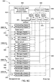
- FIGS. 6A-6C illustrate the various configurations of the information handling system 500.
- FIG. 6A exemplifies a first embodiment of the information handling system 500 configured to dynamically allocate power resources according to a server device's demands in real time.
- the ATS1 device 571 and the ATS2 device 572 are activated, while the ATS3 device 573 is inactive.
- the first and second power zones 510 and 520 receive power from the power pool 550 via the ATS1 device 571.
- the first power zone 510 is receiving 4000 Watts from the power pool 550 via the ATS1 device 571.
- the second power zone 520 is receiving 1200 Watts from the power pool 550 via the ATS1 device 571.
- an ATS device although an ATS device is active the associated power zone may not receive power.
- the ATS2 device 572 is activated, however the third power zone 530 is receiving no power.
- the central controller 560 can direct or redirect power from the power pool 550 to the power zones based on real time needs. Therefore, the ATS2 device 572 might be active while the third set of chasses 531 receives no power. The ATS2 device 572 can subsequently be inactivated. The ATS3 device 573 is inactive. As a result, the fourth set of chasses 541 within the fourth power zone 540 is not receiving any power.
- the ATS2 can be powered on during the power consumption because the central controller 560 can predict the workload will be started at a specified moment in accordance with data collected by the central controller 560. As a result, the central controller 560 can predict the next upcoming workload and prepare for it in advance.
- FIG. 6B exemplifies a second embodiment of the information handling system 500 configured to dynamically allocate power resources according to a server device's demands in real time.
- the ATS1 device 571 and the ATS2 device 572 are activated, while the ATS3 device 573 is inactive.
- the ATS1 device 571 is able to selectively send power to the first or second power zones 510 and 520.
- the first power zone 510 receives power from the power pool 550 via the ATS1 device 571
- the second power zone 520 is receiving no power from the power pool 550.
- the first power zone 510 is receiving 4000 Watts from the power pool 550 via the ATS1 device 571.
- the ATS2 device 572 is activated.
- the third power zone 530 receives power from the power pool 550 via the ATS2 device 572.
- the third power zone 530 is receiving 4000 Watts from the power pool 550 via the ATS2 device 572.
- the ATS3 device 573 is inactive. As a result, the fourth set of chasses 541 within the fourth power zone 540 is not receiving any power.
- FIG. 6C exemplifies a third embodiment of the information handling system 500 configured to dynamically allocate power resources according to a server device's demands in real time.
- the ATS1 device 571, the ATS2 device 572 and the ATS3 device 573 are activated.
- the first and second power zones are connected to the ATS1 device 571, the ATS1 device 571 is able to selectively send power to the first or second power zones 510 and 520.
- the first power zone 510 receives 4000 Watts from the power pool 550 via the ATS1 device 571
- the second power zone 520 is receiving 12000 Watts from the power pool 550.
- the ATS2 device 572 and the ATS3 device 573 are also activated.
- the third power zone 530 receives power from the power pool 550 via the ATS2 device 572.
- the third power zone 530 is receiving 4000 Watts from the power pool 550 via the ATS2 device 572.
- the fourth power zone 540 receives power from the power pool 550 via the ATS3 device 573.
- the fourth power zone 540 is receiving 5000 Watts from the power pool 550 via the ATS3 device 573.
- the central controller 560 can optimize each of the power supply units (not shown) within the power pool 550.
- FIG. 7 below, provides an example of how the power pool 550 can be optimized for performance.
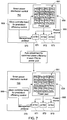
- FIG. 7 illustrates a power distribution control system 700 configured to dynamically allocate power resources according to a server device's demands in real time.
- the power distribution control system 700 can include the central controller 560 and a power pool 550.
- the power pool 550 can be connected to a power source 555.
- the power distribution control system 700 can also include a ATS1 device 571, a ATS2 device 572, and a ATS3 device 573.
- the first, second, and third ATS devices 571-573 can be controlled by the central controller 560.
- the central controller 560 can implement the ATS devices 571-573 to distribute power to a specific set of chasses.
- the central controller 560 can implement the ATS devices 571-573 by using a management protocol 570 installed on the central controller 560.
- the power pool 550 can include a plurality of power supply units 551.
- the power supply units 551 can include varying power supply performance metrics.
- the power supply units 551 vary from 90% optimization to 20% optimization.
- the central controller 560 can optimize the power supply units 551 such that all of the power supply units 551 are optimize for maximizing performance.
- the power supply units 551 are equally optimized to 50% for maximizing performance.
- the power supply units 551 can be equally optimized between 40-60%.
- the central controller 560 can monitor the PSU status of all of the power supply units 551 to re-allocate the power distribution each power supply unit to ensure the power supply unit is optimized between 40% to 60%.
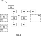
- FIG. 8 is a schematic block diagram illustrating an exemplary server system 800, in accordance with an implementation of the present disclosure.
- the server system 800 includes at least one microprocessor or processor 804; a BMC 803; one or more cooling modules 860; a main memory (MEM) 811; at least one power supply unit (PSU) 802 that receives an AC power from an AC power supply, and provides power to various components of the server system 800, such as the processor 804, north bridge (NB) logic 806, PCIe slots 860, south bridge (SB) logic 808, storage device 809, ISA slots 850, PCI slots 870, and BMC 803.
- NB north bridge
- SB south bridge
- the server system 800 After being powered on, the server system 800 is configured to load software application from memory, a computer storage device, or an external storage device to perform various operations.
- the storage device 809 is structured into logical blocks that are available to an operating system and applications of the server system 800.
- the storage device 809 is configured to retain server data even when the server system 800 is powered off.
- the main memory 811 is coupled to the processor 804 directly.
- the main memory 811 may include, but is not limited to, DRAM, double data rate DRAM (DDR DRAM), static RAM (SRAM), or other types of suitable memory.
- the main memory 811 can be configured to store firmware data of the server system 800. In some configurations, firmware data can be stored on the storage device 809.
- the server system 800 can further comprise a flash storage device.
- the flash storage device can be a flash drive, a random access memory (RAM), a non-volatile random-access memory (NVRAM), or an electrically erasable programmable read-only memory (EEPROM).
- the flash storage device can be configured to store system configurations such as firmware data.
- the processor 804 can be a central processing unit (CPU) configured to execute program instructions for specific functions. For example, during a booting process, the processor 804 can access firmware data stored in the BMC 803 or the flash storage device, and execute the BIOS 805 to initialize the server system 800. After the booting process, the processor 804 can execute an operating system in order to perform and manage specific tasks for the server system 800. In another embodiment, the BIOS 805 connects to the PCH instead of the processor 804.
- CPU central processing unit
- the processor 804 can be multi-core processors, each of which is coupled together through a CPU bus connected to the NB logic 806.
- the NB logic 806 can be integrated into the processor 804.
- the NB logic 806 can also be connected to a plurality of peripheral component interconnect express (PCIe) slots 860 and an SB logic 808 (optional).
- PCIe slots 860 can be used for connections and buses such as PCI Express x1, USB 2.0, SMBus, SIM card, future extension for another PCIe lane, 1.5 V and 3.3 V power, and wires to diagnostics LEDs on the server system 800's chassis.
- the NB logic 806 and the SB logic 808 are connected by a peripheral component interconnect (PCI) Bus 807.
- the PCI Bus 807 can support functions on the processor 804 but in a standardized format that is independent of any of the processor 804's native buses.
- the PCI Bus 807 can be further connected to a plurality of PCI slots 870 (e.g., a PCI slot 871). Devices connect to the PCI Bus 807 may appear to a bus controller (not shown) to be connected directly to a CPU bus, assigned addresses in the processor 804's address space, and synchronized to a single bus clock.
- PCI cards that can be used in the plurality of PCI slots 870 include, but are not limited to, network interface cards (NICs), sound cards, modems, TV tuner cards, disk controllers, video cards, small computer system interface (SCSI) adapters, and personal computer memory card international association (PCMCIA) cards.
- NICs network interface cards
- SCSI small computer system interface
- PCMCIA personal computer memory card international association
- the SB logic 808 can couple the PCI Bus 807 to a plurality of expansion cards or ISA slots 850 (e.g., an ISA slot 851) via an expansion bus.
- the expansion bus can be a bus used for communications between the SB logic 808 and peripheral devices, and may include, but is not limited to, an industry standard architecture (ISA) bus, PC/804 bus, low pin count bus, extended ISA (EISA) bus, universal serial bus (USB), integrated drive electronics (IDE) bus, or any other suitable bus that can be used for data communications for peripheral devices.
- ISA industry standard architecture
- PC/804 low pin count bus
- EISA extended ISA
- USB universal serial bus
- IDE integrated drive electronics
- BIOS 805 can be any program instructions or firmware configured to initiate and identify various components of the server system 800.
- the BIOS is an important system component that is responsible for initializing and testing hardware components of a corresponding server system.
- the BIOS can provide an abstraction layer for the hardware components, thereby providing a consistent way for applications and operating systems to interact with a peripheral device such as a keyboard, a display, and other input/output devices.
- the SB logic 808 is further coupled to the BMC 803 that is connected to the PSU 802.
- the BMC 803 can also be a rack management controller (RMC).
- the BMC 803 is configured to monitor operation status of components of the server system 800, and control the server system 800 based upon the operation status of the components.
- various types of electronic or computing components that are capable of processing or storing data, or receiving or transmitting signals, can also be included in the exemplary system 800.
- the electronic or computing components in the exemplary system 800 can be configured to execute various types of application, and/or can use various types of operating systems.
- These operating systems can include, but are not limited to, Android, Berkeley Software Distribution (BSD), iPhone OS (iOS), Linux, OS X, Unix-like Real-time Operating System (e.g., QNX), Microsoft Windows, Window Phone, and IBM z/OS.
- FIG. 8 is used for purposes of explanation. Therefore, a network system can be implemented with many variations, as appropriate, yet still provide a configuration of network platform in accordance with various examples of the present disclosure.
- the exemplary system 800 can also include one or more wireless components operable to communicate with one or more electronic devices within a computing range of the particular wireless channel.
- the wireless channel can be any appropriate channel used to enable devices to communicate wirelessly, such as Bluetooth, cellular, NFC, or Wi-Fi channels. It should be understood that the device can have one or more conventional wired communications connections, as known in the art. Various other elements and/or combinations are possible as well within the scope of various examples.
Landscapes
- Engineering & Computer Science (AREA)
- Theoretical Computer Science (AREA)
- Physics & Mathematics (AREA)
- General Engineering & Computer Science (AREA)
- General Physics & Mathematics (AREA)
- Software Systems (AREA)
- Computing Systems (AREA)
- Quality & Reliability (AREA)
- Mathematical Physics (AREA)
- Power Engineering (AREA)
- Power Sources (AREA)
- Remote Monitoring And Control Of Power-Distribution Networks (AREA)
- Direct Current Feeding And Distribution (AREA)
Applications Claiming Priority (1)
| Application Number | Priority Date | Filing Date | Title |
|---|---|---|---|
| US16/131,883 US10884469B2 (en) | 2018-09-14 | 2018-09-14 | Method and system for dynamically allocating and optimizing power resources |
Publications (1)
| Publication Number | Publication Date |
|---|---|
| EP3623945A1 true EP3623945A1 (de) | 2020-03-18 |
Family
ID=65013626
Family Applications (1)
| Application Number | Title | Priority Date | Filing Date |
|---|---|---|---|
| EP19151286.2A Withdrawn EP3623945A1 (de) | 2018-09-14 | 2019-01-10 | Verfahren und system zur dynamischen zuweisung und optimierung von stromressourcen |
Country Status (5)
| Country | Link |
|---|---|
| US (1) | US10884469B2 (de) |
| EP (1) | EP3623945A1 (de) |
| JP (1) | JP2020047247A (de) |
| CN (1) | CN110908485A (de) |
| TW (1) | TWI705324B (de) |
Families Citing this family (10)
| Publication number | Priority date | Publication date | Assignee | Title |
|---|---|---|---|---|
| US11126236B2 (en) * | 2019-08-14 | 2021-09-21 | Dell Products L.P. | System and method for the redirection of trapped power in a shared infrastructure environment |
| US20210176897A1 (en) | 2019-12-08 | 2021-06-10 | Nvidia Corporation | Intelligent data center having independent coolable clusters |
| CN113010999B (zh) * | 2021-02-10 | 2022-11-29 | 山东英信计算机技术有限公司 | 一种电源模块高精度均流的方法、系统及介质 |
| CN114064282B (zh) * | 2021-11-23 | 2023-07-25 | 北京百度网讯科技有限公司 | 资源挖掘方法、装置及电子设备 |
| NL2032999B1 (en) * | 2022-09-09 | 2024-03-21 | Legrand France | Power delivery system and method for delivering power |
| US20240161003A1 (en) * | 2022-11-14 | 2024-05-16 | Deer It Company | Machine learning systems and methods |
| US12585263B2 (en) | 2023-05-18 | 2026-03-24 | Quanta Computer Inc. | Systems and methods for recording events in computing systems |
| US12270848B2 (en) * | 2023-05-18 | 2025-04-08 | International Business Machines Corporation | Facilitating separately-sourced redundant power feeds to a system |
| US20260029829A1 (en) * | 2024-07-24 | 2026-01-29 | Nvidia Corp. | Mechanism for power sharing and allocation among device components |
| TWI904892B (zh) * | 2024-10-15 | 2025-11-11 | 神雲科技股份有限公司 | 電源配置方法 |
Citations (1)
| Publication number | Priority date | Publication date | Assignee | Title |
|---|---|---|---|---|
| US8843772B2 (en) * | 2012-05-22 | 2014-09-23 | Dell Products Lp | Systems and methods for dynamic power allocation in an information handling system environment |
Family Cites Families (49)
| Publication number | Priority date | Publication date | Assignee | Title |
|---|---|---|---|---|
| US5532945A (en) * | 1994-06-17 | 1996-07-02 | Intel Corporation | Power budgetting in a computer system having removable devices |
| US20030196126A1 (en) | 2002-04-11 | 2003-10-16 | Fung Henry T. | System, method, and architecture for dynamic server power management and dynamic workload management for multi-server environment |
| US6604277B2 (en) * | 2001-04-27 | 2003-08-12 | General Electric Company | Method for locking contacts in automatic transfer switch |
| US6498460B1 (en) * | 2001-12-14 | 2002-12-24 | Compaq Information Technologies Group, L.P. | Prioritization-based power management protocol in a computer system |
| US7210048B2 (en) * | 2003-02-14 | 2007-04-24 | Intel Corporation | Enterprise power and thermal management |
| US7509505B2 (en) * | 2005-01-04 | 2009-03-24 | Cisco Technology, Inc. | Method and system for managing power delivery for power over Ethernet systems |
| JP2007213167A (ja) | 2006-02-07 | 2007-08-23 | Fujitsu Ltd | 電力制御プログラム、サーバシステム、および電力制御方法 |
| US7539881B2 (en) * | 2006-04-15 | 2009-05-26 | Hewlett-Packard Development Company, L.P. | System and method for dynamically adjusting power caps for electronic components based on power consumption |
| US7555666B2 (en) * | 2006-05-04 | 2009-06-30 | Dell Products L.P. | Power profiling application for managing power allocation in an information handling system |
| US7702931B2 (en) * | 2006-06-27 | 2010-04-20 | Hewlett-Packard Development Company, L.P. | Adjusting power budgets of multiple servers |
| US8907520B2 (en) * | 2007-03-14 | 2014-12-09 | Zonit Structured Solutions, Llc | Parallel redundant power distribution |
| US7831843B2 (en) | 2006-09-26 | 2010-11-09 | Dell Products L.P. | Apparatus and methods for managing power in an information handling system |
| US7779276B2 (en) * | 2007-03-05 | 2010-08-17 | International Business Machines Corporation | Power management in a power-constrained processing system |
| EP2132759B1 (de) * | 2007-03-14 | 2016-11-02 | Zonit Structured Solutions, LLC | Schaltmodul für automatische übertragung |
| US7861102B1 (en) * | 2007-04-30 | 2010-12-28 | Hewlett-Packard Development Company, L.P. | Unified power management architecture |
| US10339227B1 (en) * | 2007-06-08 | 2019-07-02 | Google Llc | Data center design |
| JP4395800B2 (ja) * | 2007-09-18 | 2010-01-13 | 日本電気株式会社 | 電力管理システムおよび電力管理方法 |
| US8082454B2 (en) | 2007-11-07 | 2011-12-20 | International Business Machines Corporation | Managing power consumption based on historical average |
| US8006108B2 (en) * | 2007-11-08 | 2011-08-23 | International Business Machines Corporation | Dynamic selection of group and device power limits |
| US7984311B2 (en) * | 2008-08-08 | 2011-07-19 | Dell Products L.P. | Demand based power allocation |
| JP2011091955A (ja) * | 2009-10-23 | 2011-05-06 | Sony Corp | 配電システム |
| US8478451B2 (en) * | 2009-12-14 | 2013-07-02 | Intel Corporation | Method and apparatus for dynamically allocating power in a data center |
| US8589728B2 (en) * | 2010-09-20 | 2013-11-19 | International Business Machines Corporation | Job migration in response to loss or degradation of a semi-redundant component |
| JP2013041473A (ja) | 2011-08-17 | 2013-02-28 | Fujitsu Ltd | 情報処理ユニット、及び、情報処理装置 |
| US9201486B2 (en) * | 2012-02-23 | 2015-12-01 | Cisco Technology, Inc. | Large scale dynamic power budget adjustments for optimizing power utilization in a data center |
| JP2013206077A (ja) | 2012-03-28 | 2013-10-07 | Nec Corp | 電力配分システム及び電力配分方法 |
| US9021290B2 (en) | 2012-04-05 | 2015-04-28 | Oracle International Corporation | Systems and methods for dynamic power management in a blade server |
| US9081568B1 (en) * | 2012-09-25 | 2015-07-14 | Amazon Technologies, Inc. | Electrical power system with automatic transfer switch failure protection |
| CN102916835B (zh) * | 2012-10-18 | 2015-09-09 | 华为技术有限公司 | 一种调整设备功耗的方法及装置 |
| US9164557B1 (en) * | 2012-12-04 | 2015-10-20 | Amazon Technologies, Inc. | Managing power pooled from multiple shelves of a rack |
| US9620959B2 (en) * | 2013-03-15 | 2017-04-11 | Accenture Global Services Limited | Enhanced grid reliability through predictive analysis and dynamic action for stable power distribution |
| TWI566081B (zh) | 2013-03-15 | 2017-01-11 | Mitac Int Corp | Server system and its power management method |
| US9467006B2 (en) * | 2013-09-23 | 2016-10-11 | Trippe Manufacturing Company | Automatic transfer switch for three-phase applications |
| EP3099170A4 (de) * | 2013-12-26 | 2017-06-21 | Dow AgroSciences LLC | Verwendung makrocyclischer picolinamide als fungizide |
| CN105376986B (zh) * | 2014-07-16 | 2018-01-02 | 阿里巴巴集团控股有限公司 | 模块化数据中心 |
| US9414531B1 (en) * | 2014-09-24 | 2016-08-09 | Amazon Technologies, Inc. | Modular data center without active cooling |
| CN105552942A (zh) * | 2014-10-07 | 2016-05-04 | 周杰 | 防止短路或断电的电力控制系统的工作方法 |
| TWI521338B (zh) | 2015-02-04 | 2016-02-11 | 碩天科技股份有限公司 | 機房的電源管理設備及其方法 |
| US9250684B1 (en) * | 2015-02-25 | 2016-02-02 | Quanta Computer Inc. | Dynamic power capping of a subset of servers when a power consumption threshold is reached and allotting an amount of discretionary power to the servers that have power capping enabled |
| US9720476B1 (en) * | 2015-03-13 | 2017-08-01 | Amazon Technologies, Inc. | Automatic transfer switch with power quality module |
| US9537291B1 (en) * | 2015-06-08 | 2017-01-03 | Amazon Technologies, Inc. | Elevated automatic transfer switch cabinet |
| FR3045972B1 (fr) | 2015-12-17 | 2019-09-13 | Etix Labs S.A.R.L. | Brassage dynamique de l'alimentation electrique |
| US9973006B1 (en) * | 2015-12-21 | 2018-05-15 | Amazon Technologies, Inc. | Detecting misconfigured power sources for a device |
| US10432017B1 (en) * | 2016-03-15 | 2019-10-01 | Amazon Technologies, Inc. | Uninterruptable power supply (UPS) management |
| US10334334B2 (en) * | 2016-07-22 | 2019-06-25 | Intel Corporation | Storage sled and techniques for a data center |
| JP6174837B1 (ja) | 2016-12-02 | 2017-08-02 | 株式会社 エニイワイヤ | サーバラック監視システム |
| US20180203499A1 (en) | 2017-01-18 | 2018-07-19 | Quanta Computer Inc. | Power supply unit (psu) management |
| US10345888B2 (en) * | 2017-03-15 | 2019-07-09 | International Business Machines Corporation | Power capping for power consumption devices with multiple power supplies |
| US10491036B1 (en) * | 2017-03-30 | 2019-11-26 | Amazon Technologies, Inc. | Solid-state automatic transfer switch |
-
2018
- 2018-09-14 US US16/131,883 patent/US10884469B2/en active Active
- 2018-12-17 TW TW107145380A patent/TWI705324B/zh active
- 2018-12-28 CN CN201811654005.0A patent/CN110908485A/zh active Pending
-
2019
- 2019-01-10 EP EP19151286.2A patent/EP3623945A1/de not_active Withdrawn
- 2019-03-20 JP JP2019053092A patent/JP2020047247A/ja active Pending
Patent Citations (1)
| Publication number | Priority date | Publication date | Assignee | Title |
|---|---|---|---|---|
| US8843772B2 (en) * | 2012-05-22 | 2014-09-23 | Dell Products Lp | Systems and methods for dynamic power allocation in an information handling system environment |
Also Published As
| Publication number | Publication date |
|---|---|
| TWI705324B (zh) | 2020-09-21 |
| CN110908485A (zh) | 2020-03-24 |
| TW202011146A (zh) | 2020-03-16 |
| US20200089298A1 (en) | 2020-03-19 |
| JP2020047247A (ja) | 2020-03-26 |
| US10884469B2 (en) | 2021-01-05 |
Similar Documents
| Publication | Publication Date | Title |
|---|---|---|
| US10884469B2 (en) | Method and system for dynamically allocating and optimizing power resources | |
| US11061580B2 (en) | Storage device and controllers included in storage device | |
| US9519331B2 (en) | Method and apparatus for power throttling of highspeed multi-lane serial links | |
| US7992151B2 (en) | Methods and apparatuses for core allocations | |
| KR101471303B1 (ko) | 그래픽 처리 장치를 위한 전력 관리 장치 및 방법 | |
| US8239868B2 (en) | Computer system, servers constituting the same, and job execution control method and program | |
| US8032768B2 (en) | System and method for smoothing power reclamation of blade servers | |
| US20160306678A1 (en) | Automatic Analytical Cloud Scaling of Hardware Using Resource Sub-Cloud | |
| US11169846B2 (en) | System and method for managing tasks and task workload items between address spaces and logical partitions | |
| US9477485B2 (en) | Optimizing computer hardware usage in a computing system that includes a plurality of populated central processing unit (‘CPU’) sockets | |
| US10592285B2 (en) | System and method for information handling system input/output resource management | |
| US10996942B1 (en) | System and method for graphics processing unit firmware updates | |
| US11894097B2 (en) | Configuring a host interface of a memory device based on mode of operation | |
| US10114438B2 (en) | Dynamic power budgeting in a chassis | |
| US20180048559A1 (en) | Apparatus assigning controller and apparatus assigning method | |
| US11552892B2 (en) | Dynamic control of latency tolerance reporting values | |
| US20250147811A1 (en) | Workload migration between client and edge devices | |
| US20200242067A1 (en) | System and Method for I/O Aware Processor Configuration | |
| CN113703906A (zh) | 一种数据处理方法、装置及系统 | |
| US9535753B2 (en) | Context and optimization framework | |
| US11366673B1 (en) | Managing transitioning of computing system to power-on state from standby-power state | |
| US20250138877A1 (en) | Dynamic core class affinitization in an information handling system | |
| US20250139423A1 (en) | Offload multi-dependent machine learning inferences from a central processing unit | |
| EP3629188A1 (de) | Flexible kopplung von prozessormodulen | |
| US11928516B2 (en) | Greener software defined storage stack |
Legal Events
| Date | Code | Title | Description |
|---|---|---|---|
| PUAI | Public reference made under article 153(3) epc to a published international application that has entered the european phase |
Free format text: ORIGINAL CODE: 0009012 |
|
| STAA | Information on the status of an ep patent application or granted ep patent |
Free format text: STATUS: THE APPLICATION HAS BEEN PUBLISHED |
|
| AK | Designated contracting states |
Kind code of ref document: A1 Designated state(s): AL AT BE BG CH CY CZ DE DK EE ES FI FR GB GR HR HU IE IS IT LI LT LU LV MC MK MT NL NO PL PT RO RS SE SI SK SM TR |
|
| AX | Request for extension of the european patent |
Extension state: BA ME |
|
| STAA | Information on the status of an ep patent application or granted ep patent |
Free format text: STATUS: REQUEST FOR EXAMINATION WAS MADE |
|
| 17P | Request for examination filed |
Effective date: 20200330 |
|
| RBV | Designated contracting states (corrected) |
Designated state(s): AL AT BE BG CH CY CZ DE DK EE ES FI FR GB GR HR HU IE IS IT LI LT LU LV MC MK MT NL NO PL PT RO RS SE SI SK SM TR |
|
| STAA | Information on the status of an ep patent application or granted ep patent |
Free format text: STATUS: EXAMINATION IS IN PROGRESS |
|
| 17Q | First examination report despatched |
Effective date: 20210824 |
|
| STAA | Information on the status of an ep patent application or granted ep patent |
Free format text: STATUS: THE APPLICATION HAS BEEN WITHDRAWN |
|
| 18W | Application withdrawn |
Effective date: 20220114 |