EP3623695A1 - Light and method for controlling the beam characteristic of same and light mixing conductor and light with light mixing conductors - Google Patents
Light and method for controlling the beam characteristic of same and light mixing conductor and light with light mixing conductors Download PDFInfo
- Publication number
- EP3623695A1 EP3623695A1 EP19203191.2A EP19203191A EP3623695A1 EP 3623695 A1 EP3623695 A1 EP 3623695A1 EP 19203191 A EP19203191 A EP 19203191A EP 3623695 A1 EP3623695 A1 EP 3623695A1
- Authority
- EP
- European Patent Office
- Prior art keywords
- light
- optics
- coupling
- conductor
- mixer
- Prior art date
- Legal status (The legal status is an assumption and is not a legal conclusion. Google has not performed a legal analysis and makes no representation as to the accuracy of the status listed.)
- Granted
Links
- 239000004020 conductor Substances 0.000 title claims abstract description 453
- 238000002156 mixing Methods 0.000 title claims abstract description 368
- 238000000034 method Methods 0.000 title claims abstract description 29
- 230000008878 coupling Effects 0.000 claims abstract description 135
- 238000010168 coupling process Methods 0.000 claims abstract description 135
- 238000005859 coupling reaction Methods 0.000 claims abstract description 135
- 230000005855 radiation Effects 0.000 claims abstract description 52
- 238000005286 illumination Methods 0.000 claims description 86
- 238000009826 distribution Methods 0.000 claims description 45
- 239000011159 matrix material Substances 0.000 claims description 33
- 238000003384 imaging method Methods 0.000 claims description 30
- 238000013461 design Methods 0.000 claims description 20
- 230000003287 optical effect Effects 0.000 description 62
- 239000007787 solid Substances 0.000 description 62
- 230000003595 spectral effect Effects 0.000 description 45
- 239000000463 material Substances 0.000 description 32
- 239000011248 coating agent Substances 0.000 description 26
- 238000000576 coating method Methods 0.000 description 26
- 230000004075 alteration Effects 0.000 description 25
- 230000000694 effects Effects 0.000 description 22
- 238000012937 correction Methods 0.000 description 17
- 239000003795 chemical substances by application Substances 0.000 description 15
- 238000006243 chemical reaction Methods 0.000 description 12
- 239000011521 glass Substances 0.000 description 12
- 230000003993 interaction Effects 0.000 description 12
- 239000000203 mixture Substances 0.000 description 12
- 239000004033 plastic Substances 0.000 description 12
- 230000008901 benefit Effects 0.000 description 11
- 230000008859 change Effects 0.000 description 11
- 230000001419 dependent effect Effects 0.000 description 11
- 239000012780 transparent material Substances 0.000 description 11
- 239000011533 mixed conductor Substances 0.000 description 8
- 230000007704 transition Effects 0.000 description 8
- XAGFODPZIPBFFR-UHFFFAOYSA-N aluminium Chemical compound [Al] XAGFODPZIPBFFR-UHFFFAOYSA-N 0.000 description 7
- 229910052782 aluminium Inorganic materials 0.000 description 7
- 230000002093 peripheral effect Effects 0.000 description 6
- 230000009467 reduction Effects 0.000 description 6
- 239000000126 substance Substances 0.000 description 6
- 238000003491 array Methods 0.000 description 5
- 230000001788 irregular Effects 0.000 description 5
- 239000003086 colorant Substances 0.000 description 4
- 238000013507 mapping Methods 0.000 description 4
- 230000000739 chaotic effect Effects 0.000 description 3
- 238000001914 filtration Methods 0.000 description 3
- 238000004519 manufacturing process Methods 0.000 description 3
- 238000010521 absorption reaction Methods 0.000 description 2
- 230000004913 activation Effects 0.000 description 2
- 238000004026 adhesive bonding Methods 0.000 description 2
- 230000007423 decrease Effects 0.000 description 2
- 238000011161 development Methods 0.000 description 2
- 230000008030 elimination Effects 0.000 description 2
- 238000003379 elimination reaction Methods 0.000 description 2
- 239000002245 particle Substances 0.000 description 2
- 238000013519 translation Methods 0.000 description 2
- 230000003213 activating effect Effects 0.000 description 1
- 238000013459 approach Methods 0.000 description 1
- 230000005540 biological transmission Effects 0.000 description 1
- 230000001427 coherent effect Effects 0.000 description 1
- 230000006835 compression Effects 0.000 description 1
- 238000007906 compression Methods 0.000 description 1
- 238000007739 conversion coating Methods 0.000 description 1
- 230000003247 decreasing effect Effects 0.000 description 1
- 238000009792 diffusion process Methods 0.000 description 1
- 150000004291 polyenes Chemical class 0.000 description 1
- 230000003234 polygenic effect Effects 0.000 description 1
- 230000008092 positive effect Effects 0.000 description 1
- 230000008569 process Effects 0.000 description 1
- 238000007788 roughening Methods 0.000 description 1
- 230000007480 spreading Effects 0.000 description 1
- 238000003892 spreading Methods 0.000 description 1
Images


Classifications
-
- F—MECHANICAL ENGINEERING; LIGHTING; HEATING; WEAPONS; BLASTING
- F21—LIGHTING
- F21K—NON-ELECTRIC LIGHT SOURCES USING LUMINESCENCE; LIGHT SOURCES USING ELECTROCHEMILUMINESCENCE; LIGHT SOURCES USING CHARGES OF COMBUSTIBLE MATERIAL; LIGHT SOURCES USING SEMICONDUCTOR DEVICES AS LIGHT-GENERATING ELEMENTS; LIGHT SOURCES NOT OTHERWISE PROVIDED FOR
- F21K9/00—Light sources using semiconductor devices as light-generating elements, e.g. using light-emitting diodes [LED] or lasers
- F21K9/60—Optical arrangements integrated in the light source, e.g. for improving the colour rendering index or the light extraction
- F21K9/61—Optical arrangements integrated in the light source, e.g. for improving the colour rendering index or the light extraction using light guides
-
- F—MECHANICAL ENGINEERING; LIGHTING; HEATING; WEAPONS; BLASTING
- F21—LIGHTING
- F21V—FUNCTIONAL FEATURES OR DETAILS OF LIGHTING DEVICES OR SYSTEMS THEREOF; STRUCTURAL COMBINATIONS OF LIGHTING DEVICES WITH OTHER ARTICLES, NOT OTHERWISE PROVIDED FOR
- F21V13/00—Producing particular characteristics or distribution of the light emitted by means of a combination of elements specified in two or more of main groups F21V1/00 - F21V11/00
- F21V13/02—Combinations of only two kinds of elements
-
- G—PHYSICS
- G02—OPTICS
- G02B—OPTICAL ELEMENTS, SYSTEMS OR APPARATUS
- G02B27/00—Optical systems or apparatus not provided for by any of the groups G02B1/00 - G02B26/00, G02B30/00
- G02B27/09—Beam shaping, e.g. changing the cross-sectional area, not otherwise provided for
- G02B27/0938—Using specific optical elements
- G02B27/0994—Fibers, light pipes
-
- F—MECHANICAL ENGINEERING; LIGHTING; HEATING; WEAPONS; BLASTING
- F21—LIGHTING
- F21Y—INDEXING SCHEME ASSOCIATED WITH SUBCLASSES F21K, F21L, F21S and F21V, RELATING TO THE FORM OR THE KIND OF THE LIGHT SOURCES OR OF THE COLOUR OF THE LIGHT EMITTED
- F21Y2115/00—Light-generating elements of semiconductor light sources
- F21Y2115/10—Light-emitting diodes [LED]
-
- G—PHYSICS
- G02—OPTICS
- G02B—OPTICAL ELEMENTS, SYSTEMS OR APPARATUS
- G02B6/00—Light guides; Structural details of arrangements comprising light guides and other optical elements, e.g. couplings
- G02B6/0001—Light guides; Structural details of arrangements comprising light guides and other optical elements, e.g. couplings specially adapted for lighting devices or systems
- G02B6/0005—Light guides; Structural details of arrangements comprising light guides and other optical elements, e.g. couplings specially adapted for lighting devices or systems the light guides being of the fibre type
- G02B6/0008—Light guides; Structural details of arrangements comprising light guides and other optical elements, e.g. couplings specially adapted for lighting devices or systems the light guides being of the fibre type the light being emitted at the end of the fibre
Definitions
- the present invention relates to a lamp and a method for controlling the radiation characteristic of this lamp.
- luminaires are known from the prior art, which are designed to be able to influence their radiation characteristics. Different approaches are known for this. For example, it is conceivable to arrange at least one or more light-influencing optics, such as lenses or reflectors, for example, viewed in the direction of radiation or located in the beam path thereof, which optically influence the light of the illuminants for the defined light emission.
- the radiation characteristic e.g. to achieve a zoom effect
- a disadvantage of this type of optics is, on the one hand, that the optics suitable for this often only permit inadequate color mixing of the coupled-in light, so that the individual illuminants (LEDs or arrays) are partially shown in a recognizable manner.
- a comparatively complex and, in any case, a mechanically controlled device must be provided to control the zoom.
- the present invention relates to a luminaire with a light source, pre-optics and a coupling-out optics.
- the light source is divided into individually controllable light segments.
- the pre-optics have a first light coupling-in side for coupling in the light of each of the light segments of the light source and a first light coupling-out side for defined light coupling-out.
- the decoupling optics follow the optics; So downstream of the pre-optics seen in the main radiation direction of the lamp.
- the coupling optics point a second light coupling side for coupling in (or all) the light coupled out from the pre-optics and a second light coupling side for the defined light emission of the luminaire.
- the provision of individually controllable light segments makes it possible to control the emission characteristic of the defined light output by selectively controlling these light segments and thus to vary or change them.
- the mapping of the light distribution corresponding to the controlled light segments into an illumination level downstream of the decoupling optics can thus optionally be varied depending on the controlled light segments.
- the radiation characteristics and ultimately the image of the light output can thus be varied. It is also conceivable, depending on the controlled light segments, to achieve a (purely) electrical zoom effect, as will be described below.
- the light source can comprise, for example, an LED matrix which has a large number of individually controllable LEDs. These in turn form the individually controllable light segments.
- an LED matrix which has a large number of individually controllable LEDs. These in turn form the individually controllable light segments.
- Such an embodiment is preferably conceivable if the resolution of the matrix arrangement is fine enough. This is particularly useful if a single-color LED matrix arrangement is to be imaged in the illumination plane, so that, depending on the configuration of the matrix arrangement and also the activation of the controllable light segments (here LEDs), virtually any radiation characteristic can be generated.
- the light source has an elongated light mixing rod with a third light coupling side and a third light coupling side opposite the third light coupling side with respect to its elongated extent.
- the light mixing rod is divided into several segments which form the individually controllable light segments and each extend between the third light coupling side and the third light coupling side.
- the use of light mixing rods has the advantage of thorough mixing of the light colors of the light coupled into the light mixing rod or its individual segments.
- the individual segments preferably form a multiplicity of small light mixing rods which, in a suitable and preferably compact arrangement, form the elongated light mixing rod as the light source of the luminaire according to the invention. This has the advantage that the segments (i.e. the small light mixing rods) can be controlled independently of one another, and thus the radiation characteristics of the luminaire can be varied as desired.
- one or a group of individually controllable LEDs can be assigned to the segments on the side of the third light coupling side of the light mixing rod (for example as part of the aforementioned LED matrix).
- the groups of LEDs are preferably of the same type; they preferably have the same LEDs.
- the light mixing rod - that is to say its segments in each case - preferably has a length of at least 30 mm, further preferably at least 50 mm and particularly preferably at least 80 mm.
- the segments have a central rod element and ring elements and / or ring segments surrounding the central rod element on the circumference.
- the ring-shaped arrangement of the segments of the light mixing rod makes it possible to implement a purely electrical zoom by optionally connecting the segments from the inside to the outside. Depending on the design, it is thus conceivable that either rings or only ring segments can be switched individually in order to achieve a corresponding radiation characteristic and preferably a zoom effect.
- any and optionally also strongly asymmetrical light distributions can also be generated.
- At least some of the segments are formed integrally with the pre-optics. This has the advantage that, on the one hand, fewer components are required and, on the other hand, the light guidance from the light source into the pre-optics is simple and safe.
- the segments of the light mixing rod have an at least partially angular cross section.
- at least the central rod element preferably has an essentially hexagonal cross section.
- the light mixing rod or at least part of its segments merges or tapers into a defined cross-sectional shape towards the pre-optics or towards its third light output side.
- a round cross-sectional shape is particularly preferred.
- other cross-sectional shapes are also conceivable, depending on which radiation pattern is desired.
- the light source - that is to say preferably the LED matrix or the light mixing rod and in particular its third light output side - is / are preferably in contact with the first light input side of the pre-optics.
- a flat contact is particularly preferred. In this way, the light can be coupled directly and effectively from the light source into the pre-optics.
- the pre-optics can preferably have a spherical lens such as a hemispherical lens.
- the first light coupling side is preferably at least partially flat.
- the first light decoupling side can be spherical, in particular hemispherical.
- the coupling optics can preferably be a spherical lens, an aspherical lens or a Fresnel lens.
- the design of the coupling-out optics is not limited by the present invention and depends on the desired radiation characteristic.
- the decoupling optics are preferably designed such that they (entirely) absorb the light coming from the pre-optics and make them available for the defined light emission; delivers in a specifically aligned manner.
- the decoupling optics can have a flat second light coupling side, via which the light can come from the pre-optics in an effective manner and can preferably be coupled in completely.
- the luminaire can also have a scattering structure, which is preferably arranged between the pre-optics and the coupling-out optics in such a way that the light coupled out by the pre-optics is scattered before the light scattered in this way is coupled into the coupling-out optics via the second light coupling-in side. If necessary, another should be provided by means of a correspondingly provided scattering structure Soft focus of the image of the defined light emission or light distribution can be made possible.
- the scattering structure can be arranged as a separate scattering disc between the pre-optics and the decoupling optics.
- the lens can be provided relatively fixed to or directly on the decoupling optics and in particular the second light coupling side. A defined soft focus can thus be specified.
- the diffusing screen it is also conceivable to arrange the diffusing screen to be movable between the pre-optics and the decoupling optics, preferably in the light guiding direction (that is, particularly preferably in the main emission direction of the lamp).
- the lens is arranged to be movable relative to the decoupling optics.
- a movement can particularly preferably be carried out by means of a manipulation unit.
- the manipulation unit can be a mechanically or electrically adjustable unit; for example an electric motor.
- the scattering structure is provided as a surface structure directly in the coupling-out optics and in particular on the second light coupling-in side. In this way, in addition to scattering the light to soften the image, it is also possible, for example, to keep back reflections in the luminaire as low as possible.
- the present invention further relates to a method for controlling the radiation characteristic of a lamp.
- This method has the following steps: In a first step, a luminaire according to the present invention is provided.
- the individually controllable light segments for imaging a light distribution corresponding to the controlled light segments are selectively controlled in an illumination level downstream of the decoupling optics. Since the light segments can thus be controlled in any desired manner, the emission characteristic can be set electrically in a simple manner and, with appropriate control, a (purely) electrical zoom can also be realized.
- the method can also have a step of selectively moving the separate diffusing screen, preferably in the light guiding direction (for example corresponding to the main emission direction of the lamp) between the pre-optics and the decoupling optics. In particular, the movement takes place relative to the decoupling optics.
- the movement can preferably take place by means of the manipulation unit.
- the sharpness of the image of the light distribution on the lighting level is set selectively and in a defined manner.
- the present invention additionally relates to an optical mixer having a longitudinal axis and having an optical mixer body which extends axially between a light input side and a light output side.
- Light mixing conductors of the type mentioned are known from the prior art.
- such a light mixing conductor has a defined shape on its light input side, which basically corresponds to the defined geometric shape on the light output side.
- Such light mixing conductors are usually designed to be invariant in translation along their longitudinal axis.
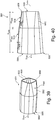
- Such a light mixing conductor 100 is shown in FIG Figure 7 shown. It is also conceivable, for example, that such a known light mixing conductor is, for example, conical, so that the shapes of the light input side and the light output side correspond, but they are designed in a different size ratio to one another.
- Such light mixing conductors can be provided as full bodies, for example.
- LEDs are used as illuminants, which use the light mixing conductor as an optical element for light mixing and light emission, there is usually no optimal mixing of the light. This is particularly the case when the individual LEDs or their different light colors are placed asymmetrically on an LED module as the illuminant.
- light mixing conductors as hollow bodies are known from the prior art. These are usually made of a highly reflective but scattering material over a wide range of angles, e.g. MCPET.
- a disadvantage of such light-mixing conductors is their lower efficiency compared to the first-mentioned light-mixing conductors as solid bodies, which direct the light through the light-mixing conductor by means of total reflection, since a relatively large amount of light is scattered back.
- the present invention therefore relates to a light mixing conductor having a longitudinal axis and having a light mixing conductor body which is located axially between a light input side with a first polygonal shape for coupling light from a light source into the light mixing conductor and a light output side with a second polygonal shape for emitting the the light input side extends coupled light.
- the first polygonal shape differs from the second polygonal shape.
- Each corner of the first polygonal shape of the light input side is connected in a straight line in the form of a longitudinal edge of the light mixing guide with a corner of the second polygonal shape of the light output side and conversely, every corner of the second polygonal shape of the light output side is rectilinear in the form of a longitudinal edge of the light mixer guide body with a corner of the first polygons Shape of the light input side connected so that the longitudinal edges do not intersect.
- the sector surfaces of the light mixer conductor body spanned between two adjacent longitudinal edges each extend flat in an extension plane.
- the cross section of the light mixer conductor changes constantly in the axial direction, so that different surface geometries or surface shapes alternate when viewed in the axial direction.
- the light can be guided through the light mixing conductor in an irregular and almost chaotic path and thus mixed much better than known light mixing conductors. This enables both good mixing of the light and efficient transmission of the light.
- shape essentially means the shape that is surrounded by the contour, regardless of its size ratio.
- polygonal shape it is understood within the scope of the invention that two polygonal shapes (that is, the shape of the Light input side compared to the light output side) from each other if they differ geometrically regardless of their size ratio, i.e. for example have a different number of corners and sides and / or if at least one of their sides has a different length than a corresponding side of the other polygonal shape and / or if the edge length of at least two sides that are connected to one another differ overall, so that a different shape results overall.
- the first polygonal shape can essentially have a rectangular or square polygonal shape or basic shape. This configuration is particularly suitable for the lamps which are usually provided. LEDs, CSP LEDs or even just LED chips themselves typically have a rectangular or square basic shape. As a result, even the most compact arrays, which consist of such light sources, have an essentially rectangular or square basic shape. Since the light input side of the light guide in this special embodiment also has a rectangular or square basic shape, very compact optical systems are possible especially with such light source arrays, which is a decisive advantage especially for the opening angle of spot or super spot optics. In such systems, the most important thing is that the smaller the light source or the virtual light source (ie the light guide output), the smaller the optical system can also be and / or the smaller opening angles of the radiation characteristic can be realized.
- a polygonal shape is by definition a shape with a defined number of corners; So a (flat) geometric figure that is formed and / or delimited by a closed route.
- the basic shape is understood to mean that the shape essentially corresponds to a polygon - that is to say, for example, is rectangular or square - but some of the corners are, for example, rounded off by a plurality of short, straight side edges, so that on the large and The result is an essentially polygonal basic shape, which in fact has a number of corners that exceeds the number of corners of the basic shape.
- the second polygonal shape can essentially have a quasi-round polygonal shape or basic shape.
- the special geometry of such a light mixing conductor thus converts the polygonal shape of the light input side into a quasi-round polygonal shape (typically a pentagon or more).
- the quasi round light output The light mixing conductor is therefore suitable for lighting optics that function close to the image.
- the light on the light output side of the light mixing conductor is well mixed due to the geometry of the light mixing conductor and thus comes from a quasi round light output surface or light output side.
- the image of the light guide output accordingly has similar properties and is therefore quasi round and particularly homogeneous in its color distribution.
- the polygonal shape has fewer corners than the second polygonal shape.
- the first polygonal shape can have a rectangular or square basic geometry
- the second polygonal shape for example, has the above-described quasi-round polygonal shape or another shape.
- the requirements on the light input side can be met (for example due to a corresponding geometry of the illuminant) and, on the other hand, an independently optimized light emission characteristic can be made possible on the light output side, which corresponds, for example, to the light output side of a classic light mixing conductor.
- the first and / or second polygonal shape can be cyclically symmetrical; in particular as a uniform polygon (such as a uniform twelve-corner).
- the first and / or second polygonal shape can furthermore be a simple and preferably convex polygon.
- the first and / or second polygonal shape can be a planar polygon, the plane of extension of which preferably extends perpendicular to the longitudinal axis.
- the first and / or second polygonal shape can also be an equilateral, equiangular or regular polygon. In this way, it is possible to design the light input side and the light output side independently of one another in any way, in order to meet the light coupling requirements on the one hand and the light decoupling requirements or the light emission characteristic on the other by individual adjustment.
- the extension planes of at least part of the sector surfaces can extend parallel to the longitudinal axis. In connection with the differing polygonal shapes on the light input side and the light output side and the resulting differing sector surfaces, particularly good light mixing can be made possible.
- the extension planes of at least some of the sector surfaces are inclined to the longitudinal axis, preferably with increasing ones Distance to the longitudinal axis from the light input side to the light output side.
- the light mixer conductor can be provided from a solid body, so that the light mixer conductor body is delimited by an outer surface surrounding the longitudinal axis.
- the light can be guided through total reflection through the light mixing conductor and, due to the special geometry of the light mixing conductor, particularly good mixing of the light and overall high efficiency of the system can be achieved.
- the light mixer conductor is provided from a hollow body, so that the light mixer conductor body is delimited by an inner surface surrounding the longitudinal axis and by an outer surface surrounding the longitudinal axis and the inner surface.
- the light mixing conductor is consequently quasi tubular.
- the sector surfaces of both the solid body and the hollow light guide formed as a hollow body can extend on the outer surface of the light mixer body.
- the sector surfaces extend on the inner surface of the light mixing conductor.
- the inner surface may be reflective and preferably mirrored, preferably provided with a reflector or a reflective coating.
- the outer surface can be designed to be reflective and preferably mirrored, preferably provided with a reflector or a reflective coating.
- a desired reflection of the light and thus a thorough mixing of the light in the light mixing conductor can thus be achieved by the light mixing conductor designed as a hollow body.
- the reflective outer surface scatter effects due to non-optimal total reflection of the light mixer can be avoided by returning any scattered light back into the light mixer.
- the outer surface of the solid-state light mixer can also be designed entirely as a reflector if the geometry of the sector surfaces does not allow or only an insufficient total reflection is permitted. The effectiveness of the light mixing conductor is thus increased overall.
- the light mixing conductor provided as a hollow body can be made of a reflective material, such as aluminum.
- the light mixing conductor provided as a hollow body and also the light mixing conductor provided as a solid body can be produced from a transparent material, such as glass or plastic.
- a reflective configuration of the sector surfaces defined for the deflection of light on the outer surface or the inner surface would then be preferred.
- the present invention further relates to a luminaire with a light mixing conductor according to the present invention and a light source or a light source, such as one or more LEDs (for example in the form of an LED module or an LED array), for coupling light into the Light mixer conductor over the light input side.
- a light source or a light source such as one or more LEDs (for example in the form of an LED module or an LED array)
- the luminaire can preferably also have pre-optics downstream of the light mixer for defined light control of the light emitted via the light output side of the light mixer.
- the luminaire can furthermore have a decoupling optic downstream of the pre-optics for defined light emission of the light emitted by the pre-optics.
- the luminaire preferably also has a scattering optics arranged between the pre-optics and the decoupling optics in order to influence the light emitted by the pre-optics.
- a scattering optics arranged between the pre-optics and the decoupling optics in order to influence the light emitted by the pre-optics.
- the present invention additionally relates to a light mixer with a longitudinal axis, which has a light mixer body, which extends axially between a light input side and a light output side. Furthermore concerns the present invention a kit of such light mixing conductors and a lamp with such a light mixing conductor or kit of light mixing conductors. Furthermore, the present invention relates to a method for generating an illumination field on an illumination level with the luminaire according to the invention.
- Light mixing conductors of the type mentioned are known from the prior art. Such light mixing conductors, which are also known as light mixing rods, are used in particular for the most homogeneous possible light mixing of light coupled into the light mixing conductor body via the light input side, which light is then emitted via the light output side. Particularly when using light mixer conductors in the spotlight area, there is often a solid angle-dependent distortion of the lighting field of a lighting system equipped with the light mixer conductor, since corresponding spotlights are usually attached to a ceiling of a room and objects (for example pictures on a wall) are typically at an angle between 10 Illuminate ° and 80 ° (usually 35 °).
- the present invention therefore relates to an optical mixer with a longitudinal axis.
- the light mixer conductor has a light mixer conductor body which extends axially between a light input side with a first shape for coupling light from a light source into the light mixer conductor and a light output side with a second shape for emitting the light coupled in via the light input side.
- the light mixer conductor By means of the light mixer conductor according to the invention, it is possible to correct a distortion of an illumination field, which is dependent on the solid angle, which is generated with a light mixer conductor, by means of the geometry of the light mixer conductor itself.
- the distortion in an illumination plane can be corrected in particular in the case of optical systems close to the image, in that the virtual light source, that is to say in particular the light output side of the light mixing conductor, is correspondingly optimized. This makes it possible, for example, in museums or shops to enable more targeted, efficient and often also aesthetically pleasing illumination of objects such as pictures, exhibits or sales items.
- the second shape of the light output side has a different or changed shape with respect to the first shape of the light input side. For example, by stretching or compressing the second shape in at least one dimension compared to the first shape, in particular in the plane transverse to the longitudinal axis, a solid angle-dependent distortion correction can be set.
- the first shape and / or the second shape each have a polygon with a defined number of corners and sides connecting the corners.
- a light mixing conductor designed in this way can be produced particularly well on the one hand.
- the first polygonal shape of the light input side it is possible to adapt it geometrically to the shape of a corresponding light source for coupling light into the light mixing conductor.
- the light input side can have a correspondingly rectangular or square shape for this purpose.
- the second polygonal shape of the light output side can also be designed in accordance with a defined light emission.
- the first and / or the second polygonal shape can essentially have a rectangular or square or quasi-round polygonal shape or basic shape.
- a polygonal shape is by definition a shape with a defined number of corners; So a (flat) geometric figure that is formed and / or delimited by a closed route.
- the basic shape is understood to mean that the shape essentially corresponds to a polygon - for example, is rectangular or square - but some of the corners are formed, for example, by a number of short, straight side edges as if rounded off, so that on the whole there is an essentially polygonal basic shape, which actually has a number of corners that exceeds the number of corners of the basic shape .
- first and / or the second polygonal shape can be cyclically symmetrical.
- the first and / or second polygonal shape can be a simple and preferably convex polygon, it can be a planar polygon whose extension plane preferably extends perpendicular to the longitudinal axis, and / or it can be an equilateral, equiangular one or trade a regular polygon.
- both the first shape and the second shape have a polygon, each with n corners and n sides. At least one, preferably at least two and particularly preferably at least two sides of the second form which are assigned or opposite one another can have a different or changed or variable side length compared to the corresponding (ie assigned or opposite) sides of the first form.
- a defined and targeted correction of a distortion of a light emitted by the light mixing conductor at a defined angle with respect to an illumination field can be achieved by targeted stretching or compression of individual sides of the same or similar polygonal shape of the light input side and the light output side.
- Each of the sides of the first shape preferably spans a sector surface with exactly one side of the second shape and, conversely, each of the sides of the second shape with exactly one side of the first shape, which particularly preferably extends in an extension plane. Due to the transition from the first shape on the light input side to the second shape on the light output side, a light mixer conductor body is formed by these sector surfaces, which results in a good and particularly homogeneous light mixing due to the change in the cross section of the light mixer conductor body seen over the longitudinal axis.
- the sector surfaces can each be formed by flat reflector plates, wherein viewed in the circumferential direction around the longitudinal axis in each case from the inner surface facing the longitudinal axis a reflector plate extends at a defined angle ⁇ an adjacent reflector plate, so that the reflector plates form a closed and preferably flower-like light mixer body.
- a light mixing conductor with different characteristics of the light input side on the one hand and the light output side on the other hand can be provided with simple means by providing defined reflector plates.
- two adjacent reflector plates each have a rectilinear contact surface.
- an angle between at least one of the extension planes of the sector surfaces or at least one of the rectilinear contact surface on the one hand and the longitudinal axis on the other hand can be set such that the second shape of the light output side and / or the first shape of the light input side can be changed , in particular the side lengths of the one, preferably of the at least two and particularly preferably of the at least two opposite sides of the second form of the light output side can be changed compared to the corresponding sides of the first form of the light input side.
- a light mixing conductor is provided, the light input side and / or light output side of which can be adjusted, so that the correction of the distortion can be adapted to the actual solid angle of the illumination field in the illumination plane.
- the light mixer conductor body formed by corresponding reflector plates, which preferably overlap in a flower-like manner, a simple adjustment of the distortion correction depending on the solid angle can be made possible. This can be done on the one hand by (radial) mechanical pressure on the light mixer conductor body, in particular on the light exit side, and thus a specifically defined deformation of the light mixer conductor.
- the light mixing conductor has an adjustment unit, such as an electric servomotor, for adjusting the reflector plates and thus for changing the first and / or second shape in order to enable the correction of the solid angle depending on the solid angle.
- an adjustment unit such as an electric servomotor
- the light mixer conductor can be provided from a solid body, so that the light mixer conductor is delimited by an outer surface surrounding the longitudinal axis.
- the light mixer conductor is provided from a hollow body, so that the light mixer conductor body is delimited by an inner surface surrounding the longitudinal axis and by an outer surface surrounding the longitudinal axis and the inner surface.
- the Reflect the inner surface and preferably be mirrored and preferably be provided with a reflector or a reflective coating.
- the outer surface to be reflective and preferably mirrored and preferably to be provided with a reflector or a reflective coating.
- the light mixer conductor or the light mixer conductor body can be made of a reflective material, such as aluminum.
- the light mixing conductor or the light mixing conductor body is made of a transparent material, such as glass or plastic. If the light mixing conductor is then designed as a solid body, the outer surface itself can already form the active surface of the light mixing conductor by means of total reflection.
- a reflective or mirrored design of the outer surface is conceivable here, for example to avoid scattering effects and to return scattered light into the light mixing conductor.
- the outer surface and / or the inner surface can preferably be designed to be reflective or mirrored, in order to enable the desired light control by the light mixing conductor.
- the present invention further relates to a kit of light mixer conductors according to the present invention, the light mixer conductors each having a different first shape of the light input side and / or a different second shape of the light output side corresponding to another defined angle ⁇ .
- the present invention further relates to a luminaire with a light mixing conductor or a kit of light mixing conductors according to the present invention.
- the luminaire has a light source for coupling light into the light mixing conductor via its light input side, so that the light thus coupled in can be emitted via the light output side.
- the light source can preferably be one or more LEDs, for example in the form of an LED array.
- the luminaire can also have a pre-optics downstream of the light mixer for defined light control of the light Light output side of the light mixing conductor emitted light, and further preferably have a coupling optics downstream of the pre-optics for defined light emission of the light emitted by the pre-optics.
- the luminaire preferably also has a scattering optics arranged between the pre-optics and the decoupling optics in order to influence the light emitted by the pre-optics.
- a particularly effective luminaire can be provided with particularly good, homogeneous light emission and distortion correction depending on the solid angle.
- an illumination field of light emitted via the light output side of a light mixing conductor in which the second form corresponds to the first form; in particular a translationally invariant light mixer.
- the angle .alpha. Can be adjusted, the first and / or second shape being changed accordingly as a function of the angle .alpha.
- the solid angle-dependent distortion correction In order to obtain the solid angle-dependent distortion correction.
- a simple method for generating an illumination field on an illumination plane with distortion correction dependent on solid angle can be provided, which moreover adjusts itself automatically and particularly preferably automatically when the angle ⁇ changes.
- the present invention additionally relates to a luminaire with a light mixing conductor and a method for controlling the radiation characteristic of this luminaire.
- Luminaires with light mixing conductors are generally known from the prior art.
- Light coupled into the light mixing conductor is homogenized with respect to the light color and light distribution and coupled out into a pre-optic via the light mixing conductor.
- the pre-optics ensure a defined light decoupling towards a decoupling optics, by means of which the final radiation characteristic is determined.
- a zoom function can be achieved, that is, the imaging scale of the luminaire can be changed on an illumination level.
- the present invention relates to a luminaire with a light source, pre-optics and a coupling-out optics.
- the light source has an illuminant for emitting light and an elongated light mixing conductor - preferably in the form of a light mixing rod - with a first light coupling side for coupling in the light emitted by the illuminant and a first light coupling side opposite the first light coupling side with regard to its elongated extension or longitudinal axis for decoupling the light of the illuminant.
- the pre-optics have a second light coupling side for coupling the light from the light source and a second light coupling side for defined light coupling out in a main light guiding direction.
- the decoupling optics follow the optics; So downstream of the pre-optics seen in the main light guide direction or main emission direction of the lamp.
- the decoupling optics have a third light coupling side for coupling in (or all) the light coupled out from the pre-optics and a third light coupling side for the defined light emission of the luminaire.
- the luminaire also has a scattering structure which is arranged between the pre-optics and the decoupling optics in such a way that the light decoupled from the pre-optics is scattered before the light scattered in this way is coupled into the decoupling optics via the third light coupling-in side.
- the scattering structure is arranged between the pre-optics and the decoupling optics and (at least) relative to the pre-optics - and preferably also relative to the decoupling optics - (essentially) in the main light guiding direction or in the main emission direction of the lamp.
- the "main light guiding direction" is a main direction of the through the individual optical elements (light mixer, Pre-optics, decoupling optics, scattering structure) each understood light beam guidance.
- This can be a light guide within the luminaire (e.g. between two optics) or the main radiation direction of the luminaire itself.
- the actual light beam guidance can have a radiation characteristic widened within the scope of a defined opening angle (for example with an opening angle of 12 ° (spot) to 40 ° (floodlight)).
- a scattering structure that is movably arranged in the main light guiding direction enables the image of the defined light emission or light distribution of the luminaire to be deliberately blurred; therefore the sharpness of the light image of the lamp can be set optionally.
- an optical mixer as part of the light source enables a largely homogeneous mixing of any color errors (e.g. chromatic aberration) of the optical system.
- the scattering structure (for example in the form of a scattering film) is positioned between the lenses of the imaging optical system - that is to say the pre-optics and the decoupling optics.
- the imaging scale (formula symbol ⁇ ) is defined as the ratio between the image size of the optical image (y ', image) of an object and its real object size (y, object).
- ⁇ y ⁇ / y
- An image scale with the amount 1 indicates that the object and its image are the same size.
- a magnification of 0.5 indicates that the object is twice the size of its image.
- An image scale with the amount 2 indicates that the image is twice as large as the object.
- the light source (that is, the illuminant and / or the light mixing conductor) is preferably divided into individually controllable light segments.
- the provision of individually controllable light segments can make it possible to control the emission characteristics of the defined light output and thus to vary or change them by selectively activating these light segments.
- the mapping of the light distribution corresponding to the controlled light segments into an illumination level downstream of the decoupling optics can thus optionally be varied depending on the controlled light segments.
- the radiation characteristics and ultimately the image of the light output can thus be varied. It is also conceivable, depending on the controlled light segments, to achieve a (purely) electrical zoom effect, as will be described below.
- the light source can comprise, for example, one or more LEDs, preferably an LED matrix.
- the LED matrix can particularly preferably have a plurality of individually controllable LEDs. These in turn can then form the individually controllable light segments of the light source, which couple light into the light mixing conductor in a defined manner.
- Such an embodiment is preferably conceivable if the resolution of the matrix arrangement is fine enough. This is particularly useful if a single-color LED matrix arrangement is to be imaged in the illumination plane, so that, depending on the configuration of the matrix arrangement and also the activation of the controllable light segments (here LEDs), virtually any radiation characteristic can be generated.
- the light mixing conductor or light mixing rod is provided as an integral (monolithic) component. Good light mixing of the light coupled in via the first light coupling-in side can thus be achieved.
- the light mixing conductor or light mixing rod is subdivided into several segments, which each extend between the first light coupling-in side and the first light coupling-out side and preferably form the individually controllable light segments.
- the use of light mixing rods in general has the advantage of thorough mixing of the light colors of the light coupled into the light mixing rod or its individual segments.
- the individual segments preferably form a multiplicity of small light mixing rods which, in a suitable and preferably compact arrangement, form the elongated light mixing rod as part of the light source of the luminaire according to the invention - namely the light mixing conductor. form.
- This has the advantage that the segments (i.e. the small light mixing rods) can be controlled independently of one another, and thus the radiation characteristics of the luminaire can be varied as desired.
- one or a group of individually controllable LEDs can be assigned to the segments on the side of the first light coupling side of the light mixing conductor (for example as part of the aforementioned LED matrix).
- the groups of LEDs are preferably of the same type; they preferably have the same LEDs.
- the light mixing conductor - in the case of segmented provision so its segments in each case - preferably has a length of at least 30 mm, further preferably at least 50 mm and particularly preferably at least 80mm.
- the segments have a central rod element and ring elements and / or ring segments surrounding the central rod element on the circumference.
- the ring-shaped arrangement of the segments of the light mixing conductor makes it possible to implement a purely electrical zoom by optionally connecting the segments from the inside to the outside. Depending on the design, it is thus conceivable that either rings or only ring segments can be switched individually in order to achieve a corresponding radiation characteristic and preferably a zoom effect.
- any and optionally also strongly asymmetrical light distributions can also be generated.
- the light mixing conductor preferably at least part of the same, particularly preferably at least part of the segments, further preferably at least the central rod element, is formed integrally with the pre-optics.
- the segments of the light mixing conductor have an at least partially angular cross section.
- points at least the central rod element has essentially a hexagonal cross section.
- the light mixing conductor or at least a part of its segments merges or tapers into a defined cross-sectional shape towards the pre-optics or towards its first light output side.
- a round or quasi-round cross-sectional shape is particularly preferred.
- an “approximately round cross-sectional shape” is understood to mean an approximately round cross-sectional shape; for example, a uniform polygon, like a uniform twelve-sided.
- other cross-sectional shapes are also conceivable, depending on which radiation pattern is desired.
- the light mixing conductor and in particular its first light coupling-out side is preferably in contact with the second light coupling-in side of the pre-optics.
- a flat contact is particularly preferred. In this way, the light can be coupled directly and effectively from the light source into the pre-optics via the light mixer.
- the pre-optics can preferably have a spherical lens such as a hemispherical lens.
- the second light coupling side is preferably at least partially flat.
- the second light output side can be spherical, in particular hemispherical.
- the coupling optics can preferably be a spherical lens, an aspherical lens or a Fresnel lens.
- the design of the coupling-out optics is not limited by the present invention and depends on the desired radiation characteristic.
- the decoupling optics are preferably designed such that they (entirely) absorb the light coming from the pre-optics and make them available for the defined light emission; delivers in a specifically aligned manner.
- the decoupling optics can have a flat third light coupling side, via which the light can come from the pre-optics in an effective manner and can preferably be coupled in completely.
- the scattering structure can be arranged as a separate scattering disc or scattering film between the pre-optics and the decoupling optics. A defined soft focus can thus be adjusted by manipulating the lens.
- the decoupling optics can also be arranged to be movable relative to the pre-optics in the main light guiding direction or in the main emission direction of the lamp.
- the imaging scale can be changed and adjusted and thus adapted to the respective lighting situation.
- the focal point of the imaging system is shifted and another object plane within the light mixing conductor is used as a virtual light source (cf. for example also Fig. 5 ).
- the scattering structure can alternatively also be provided as a surface structure directly in or on the decoupling optics, in particular on the third light coupling side. In this way, in addition to scattering the light to soften the image, it is also possible, for example, to keep back reflections in the luminaire as low as possible.
- a movement of the scattering structure and / or the coupling-out optics can preferably take place by means of a manipulation unit.
- the manipulation unit can be a mechanically or electrically adjustable unit and, in the latter case, can have, for example, an electric motor (e.g. servomotor).
- the scattering structure preferably has a beam scattering of 2 ° to 15 °, preferably 5 ° to 10 °.
- FWHM is the full width half maximum
- FWTM is the tenth width (full width tenth maximum).
- the lamp preferably has a preferably adjustable opening angle of the radiation characteristic in the range from 4 ° FWHM to 60 ° FWHM, preferably in the range from 12 ° FWHM to 40 ° FWHM, alternatively for a narrow radiation characteristic in the range from 5 ° FWHM to 25 ° FWHM, preferably from 8 ° FWHM to 16 ° FWHM.
- This ensures an easily applicable light distribution curve. It is generally assumed that the light distribution curve typically has a bell-like intensity distribution.
- the scattering structure has the particular task of softly drawing the image of the virtual light source.
- the ratio of half width (FWHM: full width half maximum) to tenth width (FWTM: full width tenth maximum) can be set by the scattering strength of the scattering structure and its position relative to the optics.
- the beam angle of the radiation characteristic is almost unchanged.
- an opening angle of the radiation characteristic of the luminaire changes from a mean value by a maximum of +/- 4 ° by moving the scattering structure (that is, by blurring or focusing), in particular relative to the pre-optics, preferably by a maximum of +/- 2 °.
- the present invention further relates to a method for controlling the radiation characteristic (in particular soft focus or focusing) of a luminaire.
- This method has the following steps: In a first step, a luminaire according to the present invention is provided. In a second step, the scattering structure in the main light guiding direction or main emission direction between the pre-optics and the decoupling optics is optionally moved (at least) relative to the pre-optics, preferably by means of the manipulation unit, that the sharpness of an image of the Light distribution is set on a lighting level downstream of the decoupling optics.
- the method can furthermore have a step of selectively moving the decoupling optics in the main light guiding direction (for example corresponding to the main emission direction of the lamp) relative to the pre-optics.
- the movement can preferably take place by means of the manipulation unit.
- the imaging scale of the illustration of the light distribution on the illumination level is set selectively and in a defined manner.
- the method can furthermore have a step for optionally individually actuating the light segments in order to image a light distribution corresponding to the activated light segments in an illumination plane downstream of the decoupling optics. Because the light segments can thus be controlled in any way, the emission characteristic can be set electrically in a simple manner and, with appropriate control, a (purely) electrical zoom can also be realized.
- the present invention additionally relates to a light mixing conductor and lamps equipped therewith.
- Light mixing conductors with a longitudinal axis are basically known from the prior art. These generally have a light mixer conductor body which extends axially between a light input side for coupling light from a light source into the light mixer conductor and a light output side for emitting the light coupled in via the light input side. At the end of the light mixing conductor or mixing rod, the light should ideally be mixed well and thus be emitted homogeneously in color as seen from the light output side.
- chromatic aberration This is an aberration in optical systems that results from the fact that light of different wavelengths or colors is refracted to different extents. This color error manifests itself particularly in color fringes at light-dark transitions in the area of the edges of an image.
- the present invention relates to a light mixer with a longitudinal axis.
- This has a light mixer conductor body, which extends axially between a light input side for coupling light from a light source into the light mixer conductor and a light output side for emitting the light coupled in via the light input side.
- the light output side is limited by a peripheral edge.
- the light mixer conductor body has means for changing the spectral composition of the light to be emitted in the region of the edge via the light output side.
- region of the edge is to be understood to mean any region assigned to the edge, for example on an outer or inner surface or on the light exit side of the light mixer conductor body. Depending on the size of the light mixing conductor, this area can extend over a distance of a few millimeters to a few centimeters or even less / more. In connection with the light exit side, this area of the edge preferably extends at least partially and preferably entirely over the exit areas responsible for chromatic aberration.
- a light mixing conductor which changes a spectral composition in a defined (exit) region - in particular in the region of the light emission which is responsible for a color error of the chromatic aberration - and thus the light emission and furthermore an image generated therefrom spectrally influenced or changes.
- the spectral range can thus be influenced in a defined manner, for example in this critical light emission range.
- the spectral composition of the light at the end of the light mixer conductor it is thus possible, by means of a specifically brought about local changes in the spectral composition of the light at the end of the light mixer conductor, to generate a light output on the light output side that is particularly homogeneous in terms of color, so that preferably the chromatic aberration of an imaging or to be combined with this light mixer conductor optical system at least reduced and ideally even eliminated or can be corrected.
- the change in the spectral composition can also be used to generate a defined color error if, for example, an image with a defined color fringe is to be generated.
- the reduction in chromatic aberration is therefore a particularly desired effect, but the present invention can in principle also be used to influence precisely this effect in a defined manner; So to reinforce or change the color, for example.
- the agent is preferably provided in the area of the edge.
- the area comprising the agent can be limited in such a way that it is only provided in a necessary functional area in order to be able to achieve a sufficient influence (for example reduction or elimination) of a chromatic aberration.
- the agent can be provided in different ways on, in or on the light mixing conductor.
- the agent can be placed on the light mixer conductor body. It can, for example, be glued on and / or attached; this, for example, on the end face surrounding the light output side or also as an extension of the light mixer conductor body.
- the means can form the area of the edge or limit the light output side. The means can therefore be provided as a separate part.
- the agent is applied to the light mixer conductor body.
- it can be provided in the form of a coating.
- the means is provided integrated in the light mixer conductor body. The agent can therefore be provided, for example, with the light mixer conductor body material.
- the agent can also be provided in other ways.
- the means can, for example, have a spectral filter for filtering out defined spectral components from the light to be emitted in the region of the edge.
- a spectral filter for filtering out defined spectral components from the light to be emitted in the region of the edge.
- suitable spectral components can be passed on, while unsuitable spectral components are filtered out and thus do not negatively influence the light output.
- the spectral filter can be designed such that it absorbs light with the defined spectral components to be filtered out.
- the spectral filter is designed such that it couples light with the defined spectral components to be filtered out in a different direction than light emitted via the light output side with spectral components not to be filtered out.
- the light can preferably be combined with the defined spectral components to be filtered out are coupled out or deflected transversely to or laterally with respect to a main emission direction of the light mixing conductor or the longitudinal axis.
- the light thus decoupled or redirected can then be emitted, for example, in or within a luminaire housing, where it is absorbed, for example.
- An effective spectral filter can thus be provided.
- the agent has color conversion substances for the defined color conversion of the light to be emitted in the area of the edge.
- the color conversion substances can be distributed in the material of the light mixer conductor body or can be provided, for example, by means of a separate color conversion element or a color conversion coating on or in the light mixer conductor body. It is thus possible to specifically counteract or influence a chromatic aberration by means of targeted color conversion and, ideally, to homogenize an image to be generated with this light mixing conductor.
- the means has illuminants for coupling light with defined spectral components into the light mixing conductor in the region of the edge.
- the additional coupling in of light with additional spectral components which is preferably coupled in at the end of the light mixing conductor, can also serve to influence chromatic aberration and, for example, counteract it in a targeted manner in order ideally to homogenize an image to be generated with the light mixing conductor.
- OLEDs organic light emitting diodes
- the light mixer conductor body is preferably delimited on the outer circumference by an outer surface surrounding the longitudinal axis.
- the light mixer conductor can preferably be provided as a solid body, so that the light mixer conductor body is delimited on the outer circumference by the outer surface surrounding the longitudinal axis.
- the light mixer conductor it is also conceivable for the light mixer conductor to be provided as a hollow body, so that the light mixer conductor body is delimited on the inner circumference by an inner surface surrounding the longitudinal axis and on the outer circumference by the outer surface surrounding the longitudinal axis and the inner surface.
- Corresponding light mixing conductors can therefore be used in a variety of ways.
- the agent can be provided as a hollow body on the inner surface, in particular in the case of a light mixing conductor.
- the agent in the case of a hollow body, it is also conceivable for the agent to be placed or plugged onto the end face forming the light output side. It is also conceivable that the agent is provided partly on the inner surface and partly on the outer surface; depending on the requirements of the light mixing conductor. It is also conceivable that the agent is provided on the outer surface. In addition, the agent can partially extend over the light output side.
- the present invention further relates to a luminaire having a light mixing conductor according to the invention and illuminants as a light source for coupling light into the light mixing conductor via its light input side, so that the light thus coupled in can be emitted via the output side.
- the luminaire can also have an optical system optically downstream of the light mixing conductor for influencing the light, such as, for example, for defined light control and / or scattering, of the light emitted via the light output side of the light mixing conductor.
- optical system optically downstream of the light mixing conductor for influencing the light, such as, for example, for defined light control and / or scattering, of the light emitted via the light output side of the light mixing conductor.
- “optically downstream” is understood to mean in particular downstream in the direction of the light beam, that is to say, for example, seen in the direction of radiation.
- the optical system can preferably have an optical system such as a light directing and / or scattering optical system, or else an optical system with a plurality of preferably optically downstream optics (for example of the aforementioned type).
- the use of the light mixing conductor according to the invention thus makes it possible to influence chromatic aberration in such an imaging system and preferably to counteract it effectively.
- the means can change a spectral composition of the light of the illuminant to be emitted in the area of the edge via the light output side in such a way that a chromatic aberration of the optical system is at least reduced or even completely eliminated.
- the present invention further relates to a light mixer with a longitudinal axis, which has a diffuse light mixer body, which extends axially between a light input side for coupling light from a light source into the light mixer and a light output side for emitting the light coupled in via the light input side.
- the light mixer conductor body has a deflection surface surrounding the longitudinal axis for deflecting (in particular reflection or total reflection) the coupled-in light. This deflection surface is used in particular for the propagation of the light coupled into the light guide towards the light exit side.
- the light mixer conductor body has starting from the light input side in the direction of the longitudinal axis, a first widening section with a first widening angle ⁇ 1 with respect to the longitudinal axis and a second widening section downstream of the first widening section with a second widening angle ⁇ 2 with ⁇ 1> ⁇ 2 with respect to the longitudinal axis.
- the widening angles ⁇ 1 and ⁇ 2 are chosen such that the light coupled in via the light input side is largely directed onto the deflection surface again after first interaction with the deflection surface.
- at least a (significant) part of the light coupled in via the light input side should preferably be redirected onto the deflection surface after the first interaction with the deflection surface.
- the light mixing conductor according to the invention differs from a reflector in that the deflecting surface is preferably selected such that after the first interaction with the deflecting surface, the light is deflected as directly as possible to the light exit side without (a substantial proportion of the light) Deflection surface hits again; So little or no interaction with the deflection surface is desired in a known reflector.
- a diffuse light mixer conductor body is to be understood as any light mixer conductor body which has diffuse optical properties, that is to say the light guided therein is diffusely distributed or scattered. This can be done, for example, by the material of the light mixer conductor body, by diffuser particles arranged (distributed) in the light mixer conductor body, by a diffuser coupled to it (for example provided on its outer or inner surface), by a structural configuration such as roughening the inner surface of a hollow one Lichtmischleiter stresses, and the like can be enabled.
- the aforementioned light mixing conductor it is possible to mix the light inside the light mixing conductor well and as homogeneously as possible by multiple interaction with the deflecting surface, while at the same time the increasing widening angle increases the distance from the opening angle of the light mixing conductor on the light input side is reduced, so that the light propagates through the light mixing conductor as effectively as possible and with high efficiency but nevertheless with sufficient interaction with the deflecting surface in order to provide an overall homogeneous light mixing on the light output side.
- a chromatic aberration can be influenced by the light provided in this way and this can preferably be counteracted or even (largely) eliminated.
- the combination of the orientation of the deflection surface due to the different expansion angles when using a diffuse light mixer body ensures a highly efficient light mixing with efficient light guidance.
- the disadvantages of known light mixing conductors can thus also be overcome.
- known diffuse light mixing conductors with a high degree of scatter have a high number of light interactions with the deflection surfaces.
- the present invention offers a significantly higher degree of efficiency, since the diffusely scattered light is effectively directed to the light output side when mixed sufficiently.
- a chromatic aberration can be counteracted, which has hitherto resulted, for example, from light-mixing conductors which have used high-gloss materials to achieve high efficiency for the deflection surface.
- the first expansion angle ⁇ 1 is preferably a constant angle and / or the second expansion angle ⁇ 2 is preferably a constant angle.
- a light mixer conductor body can thus be easily provided.
- the invention is not restricted to constant expansion angles, as long as each angular range of the first expansion angle ⁇ 1 is preferably greater than each angular range of the second expansion angle ⁇ 2.
- the first widening section can extend from the light input side in the longitudinal direction or axial direction (ie in the direction of the longitudinal axis). As a result, the first widening section begins directly on the light input side, so that effective light deflection is made possible immediately after light is coupled into the light mixing conductor.
- the second expanding section can extend in the axial direction directly from the first expanding section.
- the sections thus directly adjoin each other, so that a defined transition and a defined light control for particularly effective and homogeneous light mixing can be achieved with high efficiency.
- the second widening section can preferably extend in the longitudinal direction to the light exit side.
- the second widening section is in turn divided into n downstream widening sections with widening angles ⁇ 21 ... ⁇ 2n, one, several or all of which can be constant with respect to the longitudinal axis.
- the widening angle ⁇ 21 ... ⁇ 2n decreases with increasing distance from the light input side.
- a defined light deflection on the deflection surfaces can thus be set even more flexibly, which in turn enables increased effectiveness and efficiency of an optical system equipped with the light mixing conductor.
- At least a part or all of the adjacent widening sections preferably extend directly from one another, so that a smooth transition of the corresponding sections and thus a particularly defined light control can be made possible.
- the light mixer conductor body has an axial height H.
- the light mixer conductor can be provided as a solid body, so that the light mixer conductor body is delimited on the outer circumference by the deflecting surface as the outer surface.
- the light mixer conductor body is provided as a hollow body, so that the light mixer conductor body is delimited on the inner circumference by an inner surface surrounding the longitudinal axis and circumferentially on the outside by the longitudinal axis and the outer surface surrounding the inner surface. The inner surface and / or the outer surface can then form the deflection surface.
- the light mixing conductor is therefore very versatile.
- the light mixer conductor can be formed or produced from a diffuse material in order to diffusely scatter the light coupled into the light mixer conductor in the light mixer conductor body.
- the deflecting surface preferably has diffuse properties and more preferably has a diffuse structure or a diffuse coating or a diffuse covering and the like in order to diffusely scatter the coupled light striking the deflecting surface into the light mixer conductor body. Due to the orientation of the deflection surface according to the invention due to the different widening angles, an efficiency which is significantly higher than that of a known light mixing conductor can thus be achieved.
- the present invention further relates to a luminaire with the previously described light mixing conductor according to the third aspect of the invention as well as lamps as a light source for coupling light into the light mixing conductor via its light input side, so that the light thus coupled in can be emitted via the light output side.
- the luminaire can have an optical system optically downstream of the light mixing conductor for influencing the light, such as, for example, for defined light control and / or scattering, of the light emitted via the light output side of the light mixing conductor.
- the optical system can preferably be optics such as light directing and / or scattering optics, or one Optics arrangement with a plurality of optics preferably optically downstream of one another (for example of the type described above).
- the present invention further relates to a light mixer with a longitudinal axis.
- the light mixer conductor has a light mixer conductor body which extends axially between a light input side for coupling light from a light source into the light mixer conductor and a light output side for emitting the light coupled in via the light input side.
- the light mixer conductor body is constructed in at least two parts in the direction of the longitudinal axis. One part is designed as a solid body and another part as a hollow body. In this way, the optical advantages of light mixing conductors as solid bodies and the advantages of those as hollow bodies can be optimally combined.
- a light mixing conductor can be provided, which achieves a good and homogeneous mixing of the light passing through the light mixing conductor, so as to e.g. counteract or even eliminate chromatic aberration with the highest possible efficiency.
- the ratio of solid body to hollow body along the longitudinal axis is not limited by the invention. These can be, for example, in a ratio of 50:50, or in a different and any other ratio.
- the two or more parts of the light mixer conductor body are preferably detachably or also non-detachably connected to one another; the light mixer conductor body is consequently preferably provided as an integral component.
- a detachable variant is, for example, that the part designed as a hollow body is at least partially plugged onto the part designed as a full body. In this way, these can be plugged together or in any other way functionally aligned with one another in a non-detachable manner; for example by gluing.
- the light mixer conductor body can consequently be made available in any way and optimally adapted to the optical and structural requirements.
- the part having the light input side is preferably designed as a solid body and the part having the light output side is designed as a hollow body.
- the part having the light input side is preferably designed as a hollow body and the part having the light output side is designed as a solid body.
- the order of the parts can be selected according to the desired effects.
- both the part having the light input side and the part having the light output side can be designed as a hollow body or as a solid body.
- the one in between lying or extending parts are again arbitrarily selectable in their longitudinal extent and number.
- the optically consecutive parts that is to say parts adjacent in the direction of the longitudinal axis, are preferably provided directly adjacent to one another or adjoining or extending from one another.
- the light mixer conductor body is preferably delimited on the outer circumference by an outer surface surrounding the longitudinal axis.
- the outer surface of at least the part of the light mixer conductor body designed as a hollow body can be (at least partially) reflective, preferably have a reflective coating or a reflector element. An effective light mixing conductor is thus provided. If the outer surface of the part of the light mixer conductor body designed as a solid body is designed to be reflective, scattered light can be avoided, for example, and the efficiency of a lamp equipped with the light mixer conductor can be further increased.
- the part of the light mixer conductor body designed as a hollow body can be delimited on the inner circumference by an inner surface surrounding the longitudinal axis.
- the inner surface can be (at least partially) reflective, preferably have a reflective coating or a reflector element. An effective light mixing conductor is thus provided.
- the part of the light mixer conductor body designed as a hollow body can be produced from a reflective, preferably specular material. This can also serve as a reflector (element) for the part of the light mixing conductor designed as a solid body, if and insofar as these are connected to one another by plugging the hollow body onto the solid body. In connection with the third aspect of the invention, this material can also have diffuse properties. Thus, the part of the light mixer conductor body designed as a hollow body can be provided overall in a simple manner.
- the part of the light mixer conductor body designed as a solid body can be produced from a glass material or plastic material. In connection with the third aspect of the invention, this material can also have diffuse properties. The part of the light mixer conductor body designed as a solid body can thus also be provided in a simple manner.
- the present invention further relates to a luminaire with the previously described light mixing conductor according to the fifth aspect of the Invention and illuminant as a light source for coupling light into the light mixer via its light input side, so that the light thus coupled in can be emitted via the light output side.
- the luminaire can have an optical system optically downstream of the light mixing conductor for influencing the light, such as, for example, for defined light control and / or scattering, of the light emitted via the light output side of the light mixing conductor.
- the optical system can preferably have optics such as a light directing and / or scattering optics, or an optics arrangement with a plurality of optics which are preferably optically downstream of one another (for example of the type described above).
- FIGS. 1 , 4th and 9 show three embodiments of a lamp 1 according to the present invention.
- These luminaires 1 are all distinguished by the fact that they have a light source 2, a pre-optics 3 downstream of the light source in the light guidance direction L and a coupling-out optics 4 downstream of the pre-optics in the light guidance direction L.
- the light guide direction corresponds to the main direction that the light takes through the lamp 1; this preferably corresponds to the main emission direction H of the luminaire 1.
- the light source 2 is divided into individually controllable light segments 20.
- the light source 2 can comprise an LED matrix which has a plurality of individually controllable LEDs 21 which form the individually controllable light segments 20. Any number of LEDs can be provided in any LED matrix arrangement.
- the LEDs can be controlled individually or in groups.
- the groups of LEDs are preferably of identical design, that is to say preferably have the same LEDs.
- the light source 2 has an elongated light mixing rod 22 with a (third) light coupling side 220 and a (third) light coupling side 221 opposite the (third) light coupling side 220 with respect to its elongated extent.
- the light mixing rod 22 is divided into a plurality of segments 222, which form the individually controllable light segments 20.
- the segments 222 extend in each case longitudinally between the light coupling-in side 220 and the light coupling-out side 221 of the light mixing rod 22.
- the segments 222 can have a central rod element 222a and the central rod element 222a circumferentially surrounding ring elements 222b and / or ring segments 222c. Other arrangements of the segments 222 are also conceivable.
- the segments 222 of the light mixing rod 22 may have an at least partially angular cross section.
- at least the central rod element 222a can essentially have a hexagonal cross section.
- a cross-sectional shape that is as simple as possible while at the same time simply providing a compact structure of the light mixing rod 22, such as in particular the Figures 2 and 3rd can be seen are provided. Because around this hexagonal central rod element 222a, the elements 222b or segments 222c surrounding this circumferential side can be arranged compactly.
- the light mixing rod 22 can transition to the pre-optics 3 or to its third light coupling-out side 221 into a defined cross-sectional shape.
- a round cross-sectional shape is conceivable here.
- Figure 5 corresponds to.
- the light mixing rod 22 preferably changes into the round cross-sectional shape, this being achieved by converging (cf. Figures 5a and 5d ), Expanding (cf. Figure 5b ) or a constant cross-section (cf. Figure 5c ) is conceivable.
- one or a group of individually controllable LEDs 21 is assigned to the segments 222 on the light coupling side 220 of the light mixing rod 22.
- These LEDs 21 can be formed by the above-described LED matrix.
- a possible group of LEDs for all segments 222 or even only a part of these can also be of the same design in this exemplary embodiment; which then have the same LEDs in order to achieve a harmonious light emission.
- the light mixing rod 22 and consequently its segments 222 preferably have a length of at least 30mm, preferably at least 50mm, particularly preferably at least 80mm.
- the pre-optics 3 of the lamp 1 according to the invention have a first light coupling side 320 for coupling the light of each of the light segments 20 of the light source 2.
- the luminaire 1 is provided in such a way that the light of this light segment 20 is optionally coupled into the pre-optics via each light segment 20, provided that it is activated.
- the light coupling-out side 221 of the light mixing rod 22 preferably points to the first light coupling-in side 320 of the pre-optics 3 and is particularly preferably in (flat) contact with it or is integrally formed therewith.
- the respective LEDs are preferably directed in the radiation direction onto the light coupling side 320 of the pre-optics 3.
- the light source - preferably the LED matrix or the light mixing rod 20 and in particular its third light coupling-out side 221 - is preferably in contact with the first light coupling-in side 320 of the pre-optics 3.
- a flat contact is conceivable here, as is the case in the exemplary embodiments of FIG Figures 1 , 4th , 5 and 9 is shown.
- At least some of the segments 222 - here preferably at least the central rod element 222a - can be formed integrally with the pre-optics 3.
- the pre-optics 3 also have a first light coupling-out side 321 for defined light coupling-out.
- the pre-optics 3 can have a spherical lens like a hemispherical lens or can be designed as such.
- the first light coupling side 320 can be at least partially flat; preferably at least the area of the light coupling-in side 320 that is opposite or in contact with the light source 2.
- the first coupling-out side 321 can preferably be spherical and, in particular, hemispherical in order to appropriately pre-bundle the light before it enters the coupling-out optics 4 downstream of the pre-optics 3 enable.
- the pre-optics 3 is followed by the aforementioned decoupling optics 4; in particular in such a way that the light coupled out from the pre-optics 3 can be completely coupled into the coupling-out optics 4.
- the coupling-out optics 4 have a second light coupling-in side 420 for coupling in the ones from the pre-optics 3 decoupled light and a second light decoupling side 421 for the defined light output of the luminaire 1, as exemplified in the Figure 1 is shown.
- the decoupling optics 4 are not limited to a special shape. In particular, the shape depends on the desired radiation characteristic of the luminaire 1.
- the coupling optics 4 can be a spherical lens, an aspherical lens or also a Fresnel lens.
- the second light decoupling side 421 of the decoupling optics 4 is designed accordingly, for example in FIGS Figures 1 , 4th , 8th and 9 shown.
- the coupling-out optics 4 have a flat second light coupling-in side 420, via which the light coming from the pre-optics 3 can preferably be coupled in completely and in a targeted manner.
- the luminaire 1 according to the invention can also have a scattering structure 5.
- This is preferably arranged between the pre-optics 3 and the decoupling optics 4 and serves to (further) soften the light output achieved by means of the luminaire or to image a light distribution corresponding to the controlled light segments 20 in an illumination plane B downstream of the decoupling optics 4.
- Figures 6 and 7 refer to. While Figure 6 represents different control variants of the present invention (from left to right, ring structures are increasingly electrically connected, so that a kind of electrical zoom effect is achieved, the two right-hand representations of the Figure 6 a single light segment 20 is left out in order to achieve an asymmetrical light distribution).
- Figure 7 shows the same pictures as Figure 6 with the additional use of a scattering structure 5 according to the invention.
- the additional soft focus of the image in the illumination plane B can be clearly seen here. Consequently, the light coupled out from the pre-optics 3 is scattered by means of the scattering structure 5 before the light scattered in this way is preferably coupled into the coupling-out optics 4 via the second light coupling-in side 420.
- the scattering structure 5 can be arranged as a separate scattering disc 50 between the pre-optics 3 and the decoupling optics 4, as is exemplified in FIGS Figures 8b and 9 is shown.
- the lens as in the Figure 9 shown, be provided fixed to or directly on the coupling-out optics 4 and in particular the second light coupling-in side 420.
- the diffusing screen 50 is arranged to be movable P1, P2 and in particular relative to the decoupling optics 4 in the light guiding direction L or in the main emission direction H of the lamp 1 between the pre-optics 3 and the decoupling optics 4.
- a manipulation unit (not shown here) can be provided for moving the lens 50. This can be driven mechanically or electrically, for example.
- a diffuser 50 provided in such a movable manner is, for example, the Figure 8b refer to.
- the scattering structure 5 is provided directly in the coupling-out optics 4 and in particular on the second light coupling-in side 420 as a surface structure 51, as exemplified in the embodiment according to FIG Figure 4 is shown. Any combination of the previously described and / or other known scattering structures 5 is also conceivable.
- the luminaire 1 according to the invention can furthermore have a luminaire housing 6 in which the individual elements of the luminaire 1, that is to say in particular the light source 2, the pre-optics 3 and the decoupling optics 4 and optionally also the scattering structure 5, are arranged. Since the imaging of the light segments 20 on an illumination level B can be varied and optionally even a zoom effect can be achieved, which is generated purely electrically, by optionally controlling the light segments 20 individually, the individual elements of the luminaire 1 according to the invention can preferably be in one fixed relative arrangement to each other can be provided, which considerably simplifies the structure of the lamp 1 with variable adjustment of the radiation characteristic; For example, compared to a lamp with a mechanically adjustable zoom. Only in a preferred embodiment is it conceivable that individual elements — particularly preferably the scattering structure 5 — are additionally provided in a movable manner P1, P2.
- the individually controllable light segments 20 for imaging a light distribution corresponding to the activated light segments 20 can then be selectively actuated in an illumination level B downstream of the decoupling optics 4, in order to achieve corresponding different images.
- an optionally provided separate diffusing screen 50 preferably in the light guide direction L between the pre-optics 3 and the decoupling optics 4 and in particular relative to the decoupling optics 4, the sharpness can, for example, additionally the light image can be adjusted.
- a correspondingly provided manipulation unit is preferably used.
- the shape of the individual elements is not limited by the present invention, provided that the light source 2 couples the light-individually controllable light segments 20 accordingly into a pre-optics 3 and from this in turn can couple them into a decoupling optics 4 downstream of the pre-optics 3, in order to thus achieve a to achieve defined light output via the coupling optics 4.
- a purely electrical control and variation of the light image of the luminaire 1 according to the invention can thus be achieved.
- the cross-sectional shape of the light mixing rod 22 and its individual segments 222 is also not restricted by the invention.
- the invention also does not limit the number and color of the individual LEDs 21 and the arrangement of the LEDs 21 or the configuration of the LED matrix. Likewise, the relative arrangement of the individual elements (light source 2, pre-optics 3, decoupling optics 4, scattering structure 5) to one another is not restricted by the invention, provided that they preferably enable appropriate light guidance and imaging.
- the Figure 11 on the one hand and the Figures 12 to 15 on the other hand show two different embodiments of a light mixer 2001 according to the present invention.
- the light mixing conductors 1 each have a longitudinal axis L 2000 .
- the light mixer 2001 extends along this longitudinal axis L 2000.
- the light mixer 2001 has a light mixer body 2002 which extends axially extends between a light input side 2003 with a first polygonal shape for coupling light from a light source 2012 into the light mixer 2001 and a light output side 2004 with a second polygonal shape for emitting the light coupled in via the light input side 2003.
- the first polygonal shape differs from the second polygonal shape.
- the first polygonal shape can essentially have a rectangular or square polygonal shape or basic shape.
- a square basic shape on the light input side 2003.
- This square basic shape is formed from a twelve-sided shape, four particularly long sides being connected by two short sides.
- the first polygonal shape is actually rectangular or square and thus has four corners and four sides.
- the first polygonal shape can also be any other polygon.
- the rectangular or square shape is preferred since, in particular, corresponding illuminant arrangements (for example LED arrays) generally have a rectangular (basic) shape and thus an effective coupling of light on the light input side 2003 can be made possible.
- the second polygonal shape can have a quasi-round polygonal shape or basic shape. As shown, this is, for example, a twelve-sided shape, which due to its comparatively large number of corners 2007 and sides forms an essentially round shape - that is to say a quasi-round shape.
- the second polygonal shape can also be any other polygon.
- a defined light output side 2004 that has been optimized in accordance with the requirements can be provided.
- the first polygenic shape has as many corners 2005 as the second polygonal shape.
- the first polygonal shape actually has fewer (or even more) corners 2005 than the second polygonal shape. Both are designed as a dodecagon, but have a different shape.
- the first polygonal shape on the light input side 2003 is designed here as a quasi-square basic shape, while the second polygonal shape on the light output side 2004 has a quasi-round twelve-corner shape.
- the first and / or second polygonal shape can be cyclically symmetrical, as shown in the figures.
- the first and / or second polygonal shape can also be a simple and preferably convex polygon, as shown in the figures.
- the first and / or second polyene shape can be a planar polygon, the extension plane of which preferably extends perpendicular to the longitudinal axis L 2000 , as shown in the figures.
- the first and / or second polygonal shape can furthermore be an equilateral, equiangular or regular polygon. The latter results in particular in the exemplary embodiment shown for the second polygonal form (cf. Figure 15 ).
- the first polygonal shape is designed here as an equilateral polygon (cf. Figure 14 ).
- Each corner 2005 of the first polygonal shape of the light input side 2003 is connected in a straight line in the form of a longitudinal edge 2006 of the light mixer conductor body 2002 to a corner 2007 of the second polygonal shape of the light output side 2004 and conversely, every corner 2007 of the second polygonal shape of the light output side 2004 is rectilinear in the form of a longitudinal edge 2006 of the light mixer conductor body 2002 with a corner 2005 of the first polygonal shape of the light input side 2003 connected so that the longitudinal edges 2006 do not intersect.
- the sector surfaces 2008 of the light mixer conductor body 2002 spanned between two adjacent longitudinal edges 2006 each extend flat in one extension plane.
- the extension planes of at least part of the sector surfaces and thus the sector surfaces 2008 themselves preferably extend parallel to the longitudinal axis L 2000 . This results, for example, in the Figure 14 visible narrow sector surfaces 2080.
- the extension planes of at least part of the sector surfaces 2008 and thus the sector surfaces 2008 itself Longitudinal axis L 2000 are inclined, such as in the Figure 15 is clearly visible for the wider sector surfaces in 2081.
- the sector surfaces 2008, 2081 are preferably inclined such that they have an increasing distance from the longitudinal axis L 2000 from the light input side 2003 to the light output side 2004. This results in a partially conically expanding shape of the light mixer 2001, which in turn results in a particularly homogeneous light mixing.
- the light mixer conductor 2001 can be provided from a solid body, so that the light mixer conductor body 2002 is delimited by an outer surface A 2000 surrounding the longitudinal axis L 2000 .
- Figure 2 shows for this purpose as an alternative, an embodiment in which the light-mixing guide is provided a hollow body 2001 so that the light mixing head body 2002 I 2000 surrounding outer surface area A is bounded in 2000 by the longitudinal axis L 2000 surrounding inner surface I 2000, and a longitudinal axis L 2000 and the inner surface.
- the sector surfaces 2008 can extend on the outer surface A 2000 of the light mixer conductor body 2002.
- the sector surfaces 2008 also extend on the inner surface I 2000 of the light mixer conductor body 2002.
- the inner surface I 2000 is designed to be reflective and preferably mirrored and is preferably provided with a reflector or a reflective coating.
- the outer surface A 2000 is reflective and preferably mirrored and is preferably provided with a reflector or a reflective coating. According to the embodiment of the Figure 11 this can be advantageous, for example, to avoid undesired scattering effects of the Avoid light mixing conductor and to lead a possibly scattered light back into the light mixing conductor 2001 caused by a non-optimal total reflection.
- the light mixer 2001 can also be made of a transparent material, such as glass or plastic.
- the sector surfaces are to be arranged in such a way that the light introduced into the light mixer 2001 is reflected on the sector surfaces 2008 by means of total reflection.
- the outer surface A 2000 can be designed to be reflective, as described above.
- the surface serving for reflection ie the outer surface A 2000 or, as in Figure 13 shown, the inner surface I 2000 , is reflective.
- Figure 16 furthermore shows a luminaire 2010 according to the invention using a light mixer 2001 according to the present invention.
- the light mixing conductor 2001 is housed in a 2011 luminaire housing.
- the luminaire 2010 has a light source 2012 for coupling light into the light mixer 2001 via its light input side 2003.
- the light source 2012 can have one or more LEDs (the latter, for example, in the form of an LED array).
- the luminaire 2010 according to the invention also has a pre-optics 2013 downstream of the light mixer 2001 for defined light control of the light emitted via the light output side 2004 of the light mixer 2001. Furthermore, the luminaire 2010 according to the invention has a decoupling optic 2014 downstream of the pre-optics 2013 for the defined light emission of the light emitted by the pre-optics 2013. A scattering optics 2015 can also be provided between the pre-optics 2013 and the decoupling optics 2014 in order to optically influence the light accordingly.
- the scattering optics 2015 can, for example, be provided on the light input side (that is to say the side facing the pre-optics 2013) of the decoupling optics 2014 and preferably be formed integrally therewith; for example as a surface structure. However, it is also conceivable that the scattering optics 2015 is provided as a separate element between the pre-optics 2013 and the decoupling optics 2014.
- the light mixer 3001 has a light mixer body 3002 which extends axially between a light input side 3003 with a first shape for coupling light from a light source 3012 into the light mixer 3001 and a light output side 3004 with a second shape for emitting the light coupled in via the light input side 3003 .
- the light mixer conductor 3001 can be provided as a solid body, so that the light mixer conductor body 3002 is delimited by an outer surface A 3000 surrounding the longitudinal axis L 3000 .
- the light mixing conductor may be 3001 provided as a hollow body, so that the light mixed conductor body 3002 by the longitudinal axis L 3000 surrounding inner surface I 3000, and a longitudinal axis L 3000 and the inner surface I 3000 surrounding outer surface area A is limited 3000th
- the light mixer conductor 3001 and in particular the light mixer conductor body 3002 can be made of a transparent material, such as glass or plastic.
- the outer surface A 3000 is preferably designed such that the light propagates through the light mixing conductor 3001 by total reflection.
- the outer surface A 3000 of this light mixing conductor 3001 is designed to be reflective and preferably mirrored and is particularly preferably provided with a reflector or a reflective coating.
- the light mixing conductor 3001 in the form of a hollow body, as in Figure 20 shown, can also be made of a transparent material such as glass or plastic.
- the inner surface I 3000 and / or the outer surface A 3000 is reflective and preferably mirrored and is preferably provided with a reflector or a reflective coating.
- the light mixing conductor provided as a hollow body 3001 is made of a reflective material such as aluminum.
- a spatial angle-dependent distortion correction is carried out in a manner as if the light mixing conductor 3001 were radiating perpendicularly to an illumination plane.
- a B 3000 lighting field that is corrected for distortion correction is the Figure 19 refer to.
- the comparison also shows how an illumination field B ' 3000 of the same light mixer 3001 is designed for vertical radiation onto an illumination level E' 3000 .
- the second shape of the light output side 3004 has a different or modified shape with respect to the first shape of the light input side 3003.
- the light mixer conductor 3001 or the light mixer conductor body 3002 is compressed or stretched at least in one plane perpendicular to the longitudinal axis L 3000 on the side of the light output side 3004 with respect to the light input side 3003 in order to provide a modified shape to achieve a correction of the solid angle depending on the solid angle.
- the first shape and / or the second shape can each be a polygon with a defined number of corners 3005, 3005 'and the corners 3005, 3005' connecting sides 3006, 3006 '.
- the first shape and the second shape have a polygon each with n corners and n sides.
- the light mixing conductor 3001 the Figure 18 shows a first and a second form in the form of a dodecagon, each with twelve corners and twelve sides, while the light mixing conductor 3001 according to Figure 20 shows a first and second shape in the form of a hexagon, each with six corners and six sides.
- At least one, preferably at least two and particularly preferably at least two, assigned to one another or - as in Figure 18 shown - opposite sides 3006 'of the second form of the light output side 3004 has a different or changed or variable side length compared to the corresponding sides 3006 of the first form of the light input side 3003.
- the upper and lower side 3006 'and the right and left side 3006' compared to the corresponding sides 3006 of the first form of the light input side 3003 are longer, in order to enable a defined correction of the solid angle depending on the solid angle.
- each of the sides 3006 of the first form of the light input side 3003 can have exactly one side 3006 'of the second form of the light output side 3004 and conversely each of the sides 3006' of the second form of the light output side 3004 can have exactly one side 3006 of the first form of the light input side 3003 span a sector surface 3007, which preferably extends in an extension plane.
- an easy-to-produce light mixing conductor 3001 can be provided, which also enables particularly good and homogeneous light mixing.
- the sector surfaces may be 3007, respectively formed by flat reflector plates 3070, wherein, viewed in the circumferential direction about the longitudinal axis L 3000 respectively from the longitudinal axis L 3000 facing inner surface I 3000 a reflector plate 3070 at a defined angle ⁇ 3000 an adjacent reflector plate 3070 extends, so that the reflector plates 3070 form a closed and preferably flower-like light mixer body 3002 on the circumference.
- preferably two adjacent reflector plates 3070 each have a rectilinear contact surface K 3000 .
- An angle between the extension planes of the sector surfaces 3007 or the straight contact surfaces K 3000 on the one hand and the longitudinal axis L 3000 on the other hand can preferably be set such that the second shape of the light output side 3004 and / or the first shape of the light input side 3003 can be changed.
- a variably adjustable light mixing conductor 3001 can be provided which, depending on the angle ⁇ 3000 , can be adapted for the correction of the distortion depending on the solid angle.
- Such a light mixing conductor 3001 can furthermore have an adjusting unit, such as an electric servomotor, for adjusting the reflector plates 3070 in order to change the first and / or second shape. It is also conceivable to manually adjust the reflector plates 3070.
- an adjusting unit such as an electric servomotor
- the illustrated polygonal shape of the first and second shapes can be designed in any way.
- An essentially rectangular or square or quasi-round polygonal shape or basic shape is conceivable here, a cyclically symmetrical polygonal shape, a simple and preferably convex polygon, a planar polygon whose plane of extension preferably extends perpendicular to the longitudinal axis L, and / or an equilateral, equiangular one or regular polygon.
- the present invention can preferably also comprise a kit of light mixer conductors 3001 of the type described above, the light mixer conductors 1 each having a different first form of the light input side 3003 and / or a different angle ⁇ 3000 corresponding to another defined one have the second shape of the light output side 3004.
- the present invention further comprises a luminaire 3010 with a light mixing conductor 3001 or a kit of light mixing conductors 3001 according to the present invention.
- the light mixing conductor 3001 thus provided is provided in a luminaire housing 3011.
- the luminaire 3010 also has a light source 3012 (for example an LED or an LED array) for coupling light into the Light mixer 3001 on the light input side 3003, so that the light thus coupled in can be emitted via the light output side 3004.
- a light source 3012 for example an LED or an LED array
- the luminaire 3010 furthermore has pre-optics 3013 arranged downstream of the light mixing conductor 1 for defined light control of the light emitted via the light output side 3004 of the light mixing conductor 3001, and further preferably a decoupling optics 3014 downstream of the pre-optics 3013 for defined light emission of the pre-optics 3013 emitted light.
- a scattering lens 3015 such as a lens, can also be provided between the pre-lens 3013 and the coupling lens 3014. This can, for example, be provided on the light input side of the decoupling optics, that is to say the side of the decoupling optics 3014 facing the pre-optics 3013, or be formed integrally therewith.
- the scattering optics 3015 can be provided separately between the pre-optics 3013 and the coupling-out optics 3014.
- a method for generating an illumination field B 3000 on an illumination level E is described below.
- a lamp 3010 is provided in accordance with the present invention.
- the light fixture 3010 is arranged with the longitudinal axis L 3000 of the light mixing conductor 1001 inclined by the angle ⁇ 3000 with 0 ° ⁇ 3000 ⁇ 90 ° and preferably 10 ° ⁇ 3000 ⁇ 80 ° with respect to the illumination plane E 3000 .
- the angle ⁇ 3000 can be adjusted, the first and / or second form being changed as a function of the angle ⁇ 3000 in order to achieve the previously described effect of the solid angle-dependent distortion correction.
- FIGS 22, 23 , 24th , 26 , 27 , and 30th show four embodiments of a lamp 4001 according to the present invention.
- These luminaires 4001 are all distinguished by the fact that they have a light source 4002, a pre-optics 4003 downstream of the light source 4002 in the main light-guiding direction L 4000 and a coupling-out optics 4004 downstream of the pre-optics 4003 in the main light-guiding direction L 4000 .
- the main light guiding direction L 4000 corresponds to the main direction that the light takes through the luminaire 4001; this preferably corresponds to the main emission direction H 4000 of the luminaire 4001.
- the light source 4002 has an illuminant 4021 for emitting light and an elongate light mixing conductor 4022 (here in the form of a light mixing rod 4022) with a first light coupling side 4220 for coupling in the light emitted by the illuminant 4021 and one opposite the first light coupling side 4220 with respect to its elongated extent or longitudinal axis first light decoupling side 4221 for decoupling the light of the illuminant 4021.
- the light source 4021 may have one or more LEDs. In the latter case, it can be provided, for example, in the form of an LED matrix.
- the light source 4002 such as the embodiments of FIGS Figures 27 to 31 it can be seen that it can be divided into individually controllable light segments 4020.
- the light source 4002 can, for example, comprise an LED matrix which has a multiplicity of individually controllable LEDs 4021 which form the individually controllable light segments 4020. Any number of LEDs 4021 can be provided in any LED matrix arrangement.
- the LEDs 4021 can be controlled individually or in groups or all at the same time.
- the groups of LEDs 4021 are preferably of identical design, that is to say preferably have the same LEDs 4021.
- the light mixing conductor 4022 can be designed as an integral component.
- the light mixing conductor 4022 is therefore preferably monolithic in order to provide a simple light mixing conductor 4022.
- the light mixing conductor 4022 can also be divided into a plurality of segments 4222, which each extend longitudinally between the light coupling-in side 4220 and the light coupling-out side 4221 of the light mixing conductor 4022.
- the segments 4222 can then form the individually controllable light segments 4020.
- the segments 4222 can have a central rod element 4222a and the central rod element 4222a circumferentially surrounding ring elements 4222b and / or ring segments 4222c.
- Other arrangements of the segments 4222 are also conceivable.
- the segments 4222 of the light mixing conductor 4022 can have an at least partially angular cross section.
- at least the central rod element 4222a may have a substantially hexagonal cross section.
- a cross-sectional shape that is as simple as possible while at the same time simply providing a compact structure of the light mixing conductor 4022, such as, in particular, the Figures 28 and 29 can be seen are provided. Because around this hexagonal central rod element 4222a, the elements 4222b or segments 4222c surrounding this circumferential side can be arranged compactly.
- the light mixing conductor 4022 can transition to the pre-optics 4003 or to its (first) light coupling-out side 4221 into a defined cross-sectional shape.
- a (quasi) round cross-sectional shape is conceivable here.
- the light mixing conductor 4022 preferably changes into a (quasi) round cross-sectional shape, this being achieved by converging (cf. Figures 26a and 26d ), Expanding (cf. Figure 26b ) or a constant cross-section (cf. Figure 26c ) is conceivable.
- the embodiment of the Figures 23 and 24th shows such an embodiment.
- the light mixing conductor 4022 shown there changes from a quasi-square cross-sectional shape on its light coupling-in side 4220 to a quasi-round cross-sectional shape on its light coupling-out side 4221.
- the segments 4222 on the light coupling side 4220 of the light mixing conductor 4022 can preferably be assigned one or a group of individually controllable LEDs 4021.
- These LEDs 4021 can be formed by the above-described LED matrix.
- a possible group of LEDs for all segments 4222 or only a part of these can be of the same design; these then preferably have the same LEDs 4021 in order to achieve harmonious light emission.
- the light mixing conductor 4022 and - if present - its segments 4222 preferably have a length of at least 30 mm, preferably at least 50 mm, particularly preferably at least 80mm.
- the pre-optics 4003 of the luminaire 4001 according to the invention has a second light coupling side 4320 for coupling the light from the light source 4002 and preferably each of the light segments 4020 of the light source 4002.
- the luminaire 4001 is provided in such a way that the light from the light mixer conductor 4022 or the corresponding light segment 4020 is coupled into the pre-optics 4003 via the light mixer conductor 4022 and, in the case of a segment-like configuration, optionally via each light segment 4020, if it is actuated.
- the light coupling-out side 4221 of the light mixing conductor 4022 preferably points to the light coupling-in side 4320 of the pre-optics 4003 and is particularly preferably in (flat) contact with it or is integrally formed with it.
- the light mixing conductor 4022 and in particular its first light coupling-out side 4221 is preferably in contact with the second light coupling-in side 4320 of the pre-optics 4003.
- a flat contact is particularly preferably conceivable here, as is the case in the exemplary embodiments of FIG Figures 23 , 24th , 26 and 31 is shown.
- the light mixing conductor 4022 can be formed integrally with the pre-optics 4003. It is also conceivable, for example, for the segment-like configuration, as in Figure 31 or Figure 31a shown that only a part of the light mixing conductor 4022, such as at least a part of the segments 4222 - here preferably at least the central rod element 4222a - is formed integrally with the pre-optics 4003.
- the pre-optics 4003 also have a second light coupling-out side 4321 for defined light coupling out in the main light guiding direction L 4000 .
- the pre-optics 4003 can have a spherical lens like a hemispherical lens or can be designed as such.
- the second light coupling side 4320 can be at least partially flat be educated; preferably at least the area of the light coupling-in side 4320 facing or in contact with the light source 4002.
- the second coupling-out side 4321 can preferably be spherical and, in particular, hemispherical in order to appropriately pre-bundle the light before it enters the coupling-out optics 4004 downstream of the pre-optics 4003 enable.
- the pre-optics 4003 is followed by the aforementioned decoupling optics 4004; in particular in such a way that the light coupled out from the pre-optics 4003 can be completely coupled into the coupling-out optics 4004.
- the coupling-out optics 4004 have a third light coupling-in side 4420 for coupling in the light coupled out from the pre-optics 4003 and a third light coupling-out side 4421 for the defined light emission of the luminaire 4001, as is exemplified in FIGS Figures 24 , 26 and 27 is shown.
- the decoupling optics 4004 are not limited to a specific shape. In particular, the shape depends on the desired radiation characteristic of the luminaire 4001.
- the coupling-out optics 4004 can be a spherical lens, an aspherical lens or also a Fresnel lens.
- the third light decoupling side 4421 of the decoupling optics 4004 is designed accordingly, for example in FIGS Figures 22 , 27 , 30th , 31 and 34 shown.
- the coupling-out optics 4004 have a flat third light coupling-in side 4420, via which the light coming from the pre-optics 4003 can preferably be completely and selectively coupled in.
- the luminaire 4001 according to the invention also has a scattering structure 4005. This is arranged between the pre-optics 4003 and the decoupling optics 4004 and serves to (further) soften the light output achieved by the luminaire 4001 or to image a light distribution corresponding to the controlled light segments 4020 in an illumination level B 4000 downstream of the decoupling optics 4004.
- a scattering structure 4005 from left to right, ring structures are increasingly being electrically connected, so that a kind of electrical zoom effect is achieved, with the Figure 32 a single light segment 4020 is left out in order to achieve an asymmetrical light distribution).
- Figure 33 shows the same pictures as Figure 32 with the additional use of a scattering structure 4005 according to the invention, such as that of the lamp 4001 according to Figure 27 can be seen.
- the additional blurring of the image in the lighting level B 4000 is clearly visible here.
- the light coupled out from the pre-optics 4003 is consequently scattered by means of the scattering structure 4005 before the light scattered in this way is coupled into the coupling-out optics 4004 via the third light coupling-in side 4420.
- the scattering structure 4005 is arranged in the main light guiding direction L 4000 or in the main emission direction H 4000 of the lamp 4001 between the pre-optics 4003 and the decoupling optics 4004 and (at least) relative to the pre-optics 4003 (and preferably also relative to the decoupling optics 4004) P1 4000 , P2 4000 .
- the coupling-out 4004 may be disposed relative to the foreoptics 4003 in the main light guide direction L 4000 or in the main direction of the lamp H 4000 4001 4000 P3 movable, as described for example in Figure 26 is shown.
- the scattering structure 4005 moves together with the decoupling optics 4004, the movements of which can particularly preferably also be carried out independently of one another.
- the scattering structure 4005 is preferably arranged as a separate scattering disc or scattering film 4050 between the pre-optics 4003 and the coupling-out optics 4004, as shown in FIGS Figures 22, 23 , 24th , 26 , 27 , 34b and 34c is shown.
- the diffusing screen 4050 can preferably be moved independently of other optical elements of the luminaire 4001, such as the pre-optics 4003 or the decoupling optics 4004.
- the scattering structure 4005 is provided directly in or on the coupling-out optics 4004 and in particular on the third light coupling-in side 4420 as a surface structure 4051, as is exemplified in the embodiments according to FIG Figures 30 or 34a is shown when the decoupling optics 4004 are designed to be correspondingly movable. Any combination of the previously described scattering structures 4005 - that is to say independently and depending on the coupling-out optics 4004 movable scattering structures 4005 - is also conceivable.
- a manipulation unit (not shown here) for moving the scattering structure 4005 and / or the coupling-out optics 4004 can be provided. This can be driven mechanically or electrically, for example.
- the scattering structure 4005 preferably has a beam scattering of 2 ° to 15 °, preferably 5 ° to 10 °. However, the invention is not limited to this.
- FWHM denotes the full width half maximum and FWTM the tenth width (full width tenth maximum).
- the scattering structure 4005 can thus be sufficiently moved in both directions - that is, preferably along the main light guiding direction L 4000 or main emission direction H 4000 to the pre-optics 4003 or to the decoupling optics 4004 - in order to image the light distribution on an illumination plane B 4000 downstream of the decoupling optics 4004 sharper (cf. Figure 24b combined with Figure 25b ) or softer (cf. Figure 24a combined with Figure 25a ) to set.
- the luminaire 4001 preferably has an opening angle of the radiation characteristic in the range from 4 ° FWHM to 60 ° FWHM, preferably in the range from 12 ° FWHM to 40 ° FWHM, alternatively for a narrow radiation characteristic in the range from 5 ° FWHM to 25 ° FWHM, preferably from 8 ° FWHM to 16 ° FWHM, on.
- This opening angle can, like that Figure 26 shows, for example, can also be adjustable with movable coupling optics 4004.
- an opening angle of the radiation characteristic of the luminaire 4001 changes from an average value by a maximum of +/- 4 ° by moving the scattering structure 4005 relative to the pre-optics 4003, preferably by a maximum of +/- 2 °.
- a defined fine adjustment of the light distribution can thus be achieved essentially while maintaining the desired imaging scale of the optical system when using a light mixing guide 4022 for thorough mixing of the light.
- the luminaire 4001 according to the invention can also have a luminaire housing 4006 in which the individual elements of the luminaire 4001, that is to say in particular the light source 4002 with the illuminant 4021 and light mixing conductor 4022, the pre-optics 4003, the scattering structure 4005 and the coupling-out optics 4004 are arranged.
- the scattering structure can then 4005 can be moved in the main light guiding direction between the pre-optics 4003 and the decoupling optics 4004 and relative to the pre-optics 4003, preferably by means of the manipulation unit, in order to adjust the sharpness of an image of the light distribution on an illumination plane B 4000 downstream of the decoupling optics 4004.
- the present invention it is thus possible, using an optical system with a light source 4002 having a light mixing conductor 4022, one of these pre-optics 4003 downstream, one of these scattering structures 4005 and one of these downstream coupling-out optics 4004 by means of a movable arrangement of the scattering structure 4005 to make a fine adjustment (sharper or softer adjustment) of the light distribution while essentially maintaining an image scale of the optical system and achieving good light mixing and thus a reduction or avoidance of color errors.
- the image of the individual light segments can be softened or sharpened in any way in order to achieve an overall particularly harmonious light image.
- the use of the light mixing conductor 4022 enables a particularly homogeneous light mixing and thus an overall homogeneous light emission or light image can be achieved.
- the imaging scale of the imaging of the light distribution on the illumination level B 4000 can also be set.
- a correspondingly provided manipulation unit is preferably also used.
- the individually controllable light segments 4020 for imaging a light distribution corresponding to the controlled light segments 4020 can also be individually controlled in an illumination level B 4000 downstream of the decoupling optics 4004, in order to achieve corresponding different images. It is thus additionally possible to easily achieve the imaging of a light fixture 4001 by means of electrical control of individually controllable light segments 4020 - by means of a light distribution corresponding to the controlled light segments 4020 - in an illumination level B 4000 downstream of the light fixture 4001 or its decoupling optics 4004. So lets themselves, such as in the Figures 32 and 33 shown to achieve a purely electrical zoom effect.
- the figures all show a light mixing conductor 5001 with a longitudinal axis L 5000 .
- the light mixer 5001 has a light mixer body 5002 which extends axially between a light input side 5003 for coupling light from a light source 5014 into the light mixer 5001 and a light output side 5004 for emitting the light coupled in via the light input side 5003.
- the light mixer conductor body 5002 is preferably delimited on the outer circumference by an outer surface A 5000 surrounding the longitudinal axis L 5000 .
- the light mixer conductor 5001 can be provided as a solid body, so that the light mixer conductor body 5002 is then delimited on the outer circumference by the outer surface A 5000 surrounding the longitudinal axis L 5000 .
- the light mixed conductor is provided 5001 as a hollow body, so that the light mixed conductor body 5002 by the longitudinal axis L 5000 surrounding inner surface I 5000 inner circumference and the longitudinal axis L 5000 and the inner surface I 5000 surrounding The outer surface of the A 5000 is limited on the outside.
- the light mixer conductor 5001 and in particular the light mixer conductor body 5002 can be made from a transparent material, such as glass or plastic. If the light mixing conductor 5001 is designed as a solid, the outer surface A 5000 is preferably designed in such a way that the light propagates through the light mixing conductor 5001 by total reflection. In order to avoid possible leakage losses, it is conceivable and, under certain circumstances, also preferred that the outer surface A 5000 of this light mixing conductor 5001 is designed to be reflective and preferably mirrored, and is particularly preferably provided with a reflector or a reflective coating.
- the light mixing conductor 5001 in the form of a hollow body can also be made of a transparent material, such as glass or plastic. be made.
- the inner surface I 5000 and / or the outer surface A 5000 is reflective and preferably mirrored and is preferably provided with a reflector or a reflective coating.
- the light mixing conductor 5001 provided as a hollow body is made of a reflective material, such as aluminum.
- the light output side 5004 is delimited by a peripheral edge 5005.
- the edge 5005 has a hexagonal shape in the illustrated exemplary embodiments. However, it is also conceivable that the edge 5005 has a different shape. However, a polygonal shape is preferred, such as the hexagonal shape shown or, for example, also a twelve-sided shape.
- the light input side 5003 is likewise delimited by a peripheral edge 5006. This can take the same form (cf. Fig. 35-37 ) or another form (cf. Fig. 38-40 ) have as the light output side 5004.
- the light input side 5003 here has, for example, a square basic shape, which is adapted, for example, to a corresponding illuminant 5014 (for example LED module), and which is converted into an essentially round (here, for example, 12-cornered) shape to create a desired round image.
- a square basic shape which is adapted, for example, to a corresponding illuminant 5014 (for example LED module), and which is converted into an essentially round (here, for example, 12-cornered) shape to create a desired round image.
- the light mixer conductor body 5002 can have means 5007 for changing the spectral composition of the light to be emitted in the region B 5000 of the edge 5005 via the light output side 5004.
- the means 5007 can also be provided in the region B 5000 of the edge 5005.
- the means 5007 can be placed on the light mixer conductor body 5002, for example by being plugged on and / or glued on, as is shown, for example, in FIG Figure 35 is shown.
- the agent 5007 is applied to the light mixer conductor body 5002; for example in the form of a coating, as for example in Figure 36 is shown.
- the means 5007 to be provided integrated in the light mixer conductor body 5002, for example by being integrated in the light mixer conductor body material.
- the means 5007 can, as for example in Figure 36 shown, be provided on the inner surface I 5000 . As an alternative or in addition, it is also conceivable for the means 5007 to be provided on the outer surface A 5000 . In the example of the Figure 35 means 5007 is provided both on the inner surface I 5000 and on the outer surface A 5000 . In the illustrated embodiment of the Figure 35 The means 5007 forms the area B 5000 of the edge 5005 by forming an extension of the light mixer conductor body 5002 and thus also the light output side 5004.
- means 5007 can have a spectral filter for filtering out defined spectral components from the light to be emitted in area B 5000 of edge 5005.
- the spectral filter can be designed such that it absorbs light with the defined spectral components to be filtered out.
- the spectral filter is designed to couple light with the defined spectral components to be filtered out in a different direction than light emitted via the light output side 5004 with spectral components not to be filtered out.
- the light with the defined spectral components to be filtered out is preferably coupled out transversely to or to the side with respect to a main emission direction S 5000 of the light mixing conductor 5001 or the longitudinal axis L 5000 .
- the light thus coupled out can then be introduced, for example, into a luminaire housing of a luminaire 5010 equipped with the light mixing conductor 5001, where it is absorbed, for example.
- spectral components can be filtered out and forwarded, for example, to an imaging system 5011, while unsuitable or undesired spectral components are ultimately filtered out, so that, for example, chromatic aberration can be counteracted in a targeted manner and the image of an optical one equipped with this light mixer conductor 5001 Systems 5011 can ideally be homogenized.
- the agent has 5007 color conversion substances for the defined color conversion of the light to be emitted in the area B 5000 of the edge 5005.
- the color conversion substance is provided on the inner edge in the region of the light exit side 5004 of the light mixing conductor 5001.
- the means 5007 can have a luminous means for coupling light with defined spectral components into the light mixer 5001 in the region B 5000 of the edge 5005.
- By coupling in additional light of corresponding spectral components at the end of the light mixer 5001 - i.e. on the light output side 5004 - it is possible, for example, to counteract chromatic aberration in a targeted manner and, if such a light mixer 5001 is used, an appropriate image is ideally homogenized in an optical system 5011.
- the illuminants as means 5007 can be, for example, LEDs and preferably OLEDs, in particular printed OLEDs. These can be provided in a particularly space-saving manner.
- a lamp 5010 with a light mixing conductor 5001 according to the present invention.
- the lamp 5010 also has illuminants 5014 for coupling light into the light mixer 5001 via its light input side 5003, so that the light thus coupled in can be emitted via the light output side 5004.
- the luminaire 5010 can furthermore have an optical system 5011, which is optically downstream of the light mixing conductor 5001, for influencing the light, for example for defined light control and / or scattering, of the light emitted via the light output side 5004 of the light mixing conductor 5001.
- the optical system 5011 preferably has an optical system 5012, 5013 such as a light directing and / or scattering optical system, or, as in FIG Figure 37 shown, an optical arrangement with a plurality of optics 5012, 5013, preferably optically downstream of one another.
- an optical system 5012, 5013 such as a light directing and / or scattering optical system, or, as in FIG Figure 37 shown, an optical arrangement with a plurality of optics 5012, 5013, preferably optically downstream of one another.
- the means 5007 can preferably change a spectral composition of the light of the illuminant 5014 to be emitted in the region B 5000 of the edge 5005 via the light output side 5004 such that a chromatic aberration of the optical system 5011 is at least reduced or even eliminated.
- a chromatic aberration of the optical system 5011 is at least reduced or even eliminated.
- the light mixer conductor body 5002 shown there has a deflection surface 5020 surrounding the longitudinal axis L 5000 for deflecting the coupled-in light. If the light mixer conductor 5001 is provided as a solid body, the light mixer conductor body 5002 is delimited on the outer circumference by the deflecting surface 5020 as the outer surface A 5000 . Is the light mixed conductor provided 5001 as a hollow body, the light mixing head body through which the longitudinal axis L 5000 surrounding inner surface I 5000 and the longitudinal axis L 5000 and the inner surface I 5000 surrounding outer surface A 5000 bounded on the outside peripheral side the inner peripheral side 5002, wherein the inner surface I 5000 and / or the outer surface A 5000 form the deflection surface 5020.
- the light mixer conductor body 5002 is a diffuse light mixer conductor body 5002. This can be achieved by the light mixer conductor body 5002 being produced from a diffuse material (for example, this material has diffuser particles) around which the light coupled into the light mixer conductor 5001 diffusely to scatter the light mixer conductor body 5002.
- the deflection surface 5020 can also have diffuse properties.
- the deflection surface 5020 can preferably have a diffuse structure or a diffuse coating or a diffuse cover or any combination thereof. This in particular in order to diffusely scatter or distribute the coupled light striking the deflection surface 5020 in the light mixer conductor body 5002. In principle, it is also conceivable that the deflection surface 5020 is a mirror surface.
- the deflecting surface 5020 is provided as a solid body solely by the outer surface A 5000, for example of a light guide 5001, so that a deflection of light is generated by total reflection or a reflection means having the outer surface A 5000 .
- the light mixer conductor body 5002 shown there starting from the light input side 5003 in the direction of the longitudinal axis L 5000, has a first widening section 5030 with a first widening angle ⁇ 1 5000 with respect to the longitudinal axis L 5000 (here constant) and a second widening downstream of the first widening section Section 5040 with a second expansion angle ⁇ 2 5000 with respect to the longitudinal axis L 5000 (here constant).
- ⁇ 1 5000 is larger than ⁇ 2 5000 .
- the widening angles ⁇ 1 5000 and ⁇ 2 5000 are also selected such that the light coupled in via the light input side 5003 is largely as possible after the first interaction with the deflection surface 5020, the deflection surface 5020 is again directed so that multiple interaction with the deflection surface 5020 is achieved in the light mixer conductor body 5002, while at the same time the most effective light deflection and propagation of the light within the light conductor 5001 to the light output side is achieved by the given angles 5004 can be achieved. As a result, the light is mixed as homogeneously as possible with a comparatively high efficiency.
- the first widening angle ⁇ 1 5000 can preferably be selected in an angular range of 35 ° ⁇ ⁇ 1 5000 5 5 ° and is preferably approximately 20 °.
- the second widening angle ⁇ 2 5000 can preferably be in an angle range of 15 ° ⁇ ⁇ 2 5000 ⁇ 0 ° (cf. Fig. 39 ) or in an angle range of 15 ° ⁇ ⁇ 2 5000 > 0 ° (cf. Fig. 38 and 40 ) can be selected and is preferably approximately 5 °.
- ⁇ 1 5000 >> ⁇ 2 5000 is particularly preferred.
- the ratio of the first widening angle ⁇ 1 5000 to the second widening angle ⁇ 2 5000 is preferably in a value range of 15 ⁇ ⁇ 1 5000 / ⁇ 2 5000 1,5 1.5 and is particularly preferably approximately 4. This results in preferred angular ranges of the individual sections 5030, 5040 to each other in order to achieve the most effective possible light mixing with high efficiency.
- the first widening section 5030 can extend from the light input side 5003 in the longitudinal direction L 5000 .
- the second widening section 5040 can extend in the longitudinal direction L 5000 directly from the first section 5030, so that they consequently adjoin one another directly.
- the second widening section 5040 can also extend in the longitudinal direction L 5000 to the light output side 5004. This results, for example, in the Figures 38 to 40 Shown embodiment of the light mixer 5001.
- the second widening section 5040 is in turn subdivided into n widening sub-sections with widening angles ⁇ 21 5000 ... ⁇ 2n 5000 , some or all of which can be constant with respect to the longitudinal axis L 5000 .
- the widening angle ⁇ 21 5000 ... ⁇ 2n 5000 decreases with increasing distance from the light input side 5003.
- the light mixing conductor 5001 can be further adapted to the desired requirements, in order to further preferably achieve an even greater effectiveness with regard to homogeneous light mixing with a simultaneously high relative efficiency.
- At least a part or all of the respectively adjacent widening sections can each extend directly from one another, so that overall the sections are formed adjacent to one another, which not only facilitates the production of such a light guide 5001, but also has a positive effect on its effectiveness and efficiency.
- the light mixer conductor body 5002 has an axial height H 5000 .
- the first widening section has an axial height H1 5000 .
- This axial height H1 5000 is preferably selected in a range of 1 / 2H 5000 H H1 5000 1 1 / 5H 5000 and is particularly preferably 1 / 3H 5000 .
- the second expanding section 5040 has an axial height H2 5000 .
- the axial height H2 5000 is preferably selected in a range between 4 / 5H 5000 H2 H2 5000 1 1 / 2H 5000 and is particularly preferably 2 / 3H 5000 .
- a luminaire 5010 with the light mixer 5001 according to the example in the Figures 38 to 40 Aspect of the present invention shown as well as lamps 5014 as a light source for coupling light into the light mixer 5001 via its light input side 5003, so that the light thus coupled in can be emitted via the light output side 5004.
- a luminaire 5010 provided in this way can furthermore have an optical system 5011, which is optically downstream of the light mixing conductor 5001, for influencing the light, for example for defined light control and / or scattering, of the light emitted via the light output side 5004 of the light mixing conductor 5001.
- the optical system 5011 preferably has an optical system 5012, 5013 such as a light directing and / or scattering optical system, or an optical system as in FIG Figure 37 shown, with a plurality of optics 5012, 5013 which are preferably optically downstream of one another.
- an optical system 5012, 5013 such as a light directing and / or scattering optical system, or an optical system as in FIG Figure 37 shown, with a plurality of optics 5012, 5013 which are preferably optically downstream of one another.
- the light mixer conductor body 5002 shown there is constructed in the direction of the longitudinal axis L 5000 at least in two parts (or also in any number of parts).
- a part 5021 is designed as a solid body and another part 5022 as a hollow body.
- the part 5022 of the light mixer conductor body 5002 designed as a hollow body can be made of a reflective, preferably specular material.
- the as Part 5021 of the light mixer conductor body 5002, which is formed as a solid body, can be produced from a glass material or plastic material.
- the parts 5021, 5022 of the light mixer conductor body 5002 can be detachably connected to one another. This is done, for example, in that part 5022 designed as a hollow body is at least partially plugged onto part 5021 designed as a solid body.
- the parts 5021, 5022 of the light mixer conductor body 5002 provided in this way or in another way can also be permanently connected to one another, for example by gluing.
- the part 5021 having the light input side 5003 is designed as a solid body and the part 5022 having the light output side 5004 is designed as a hollow body. Basically, however, it is also conceivable vice versa.
- the light mixer conductor body 5002 can be delimited on the outer circumference by an outer surface A 5000 surrounding the longitudinal axis L 5000 ; this consequently applies equally to both parts 5021, 5022 of the light mixer conductor body 5002, which preferably have a common outer surface A 5000 , that is to say coherent or extending without gaps from one another.
- the outer surface A 5000 of at least part 5021 of the light mixer conductor body 500 which is designed as a hollow body, can be (at least partially) reflective and preferably have a reflective coating or a reflector element.
- the part 5022 of the light mixer conductor body 5002 designed as a hollow body can moreover be delimited on the inside by an inner surface I 5000 surrounding the longitudinal axis L 5000 .
- the inner surface I 5000 can be (at least partially) reflective and preferably have a reflective coating or a reflector element.
- a lamp 5010 with the light mixer 5001 can also be a lamp 5010 with the light mixer 5001 according to the example in the Figures 41 and 42 Aspect of the present invention shown as well as lamps 5014 as a light source for coupling light into the light mixer 5001 via its light input side 5003, so that the light thus coupled in can be emitted via the light output side 5004.
- a lamp 5010 provided in this way also have an optical system 5011, which is optically downstream of the light mixing conductor 5001, for influencing the light, for example for defined light control and / or scattering, of the light emitted via the light output side 5004 of the light mixing conductor 5001.
- the optical system 5011 preferably has an optical system 5012, 5013, such as a light directing and / or scattering optical system (cf. Figures 41 and 42 ), or an optical arrangement with several optics 5012, 5013, preferably optically downstream of one another (cf. Figure 37 ) on.
- an optical system 5012, 5013 such as a light directing and / or scattering optical system (cf. Figures 41 and 42 ), or an optical arrangement with several optics 5012, 5013, preferably optically downstream of one another (cf. Figure 37 ) on.
- a light mixing conductor 5001 can also be provided, which on the one hand has a first and a second widening section 5030, 5040 according to FIG Figures 38 to 40 and also one in the Figures 35 to 37 exemplified means for changing the spectral composition of the light to be emitted in the area B 5000 of the edge 5005 via the light output side 5004.
- a light mixing conductor 5001 can also be provided, which on the one hand has a first and a second widening section 5030, 5040 according to FIG Figures 38 to 40 and also a two or more divided form according to the Figures 41 and 42 having.
- the parts 5021, 5022 can, for example, be selected in accordance with the widening sections 5030, 5040 and preferably correspond to one another.
- a light mixing conductor 5001 can also be provided, which on the one hand has a two-part or multi-part shape according to FIG Figures 41 and 42 and also that in the Figures 35 to 37 has exemplified means for changing the spectral composition of the light to be emitted in the region B 5000 of the edge 5005 via the light output side 5004. It is also conceivable that a light mixing conductor 5001 is provided, which has the aforementioned features of all three aspects. All of this, of course, in any form as described above in the context of the present invention.
- a luminaire 1 comprising: a light source 2, the light source 2 being subdivided into individually controllable light segments 20, pre-optics 3 with a first light coupling side 320 for coupling the light from each of the light segments 20 of the light source 2 and a first light coupling side 321 for defined light coupling, and a coupling optics 4 downstream of the pre-optics 3 with a second light coupling-in side 420 for coupling in the light coupled out from the pre-optics 3 and a second light coupling-out side 421 for defined light emission.
- the light source 2 can comprise an LED matrix, which has a plurality of individually controllable LEDs 21, which form the individually controllable light segments 20.
- the light source 2 can have an elongated light mixing rod 22 with a third light coupling side 220 and a third light coupling side 221 opposite the third light coupling side 220 with respect to its elongated extent, wherein the light mixing rod 22 can be divided into a plurality of segments 222, which form the individually controllable light segments 20 each extend between the third light coupling side 220 and the third light coupling side 221.
- the segments 222 can have a central rod element 222a and the central rod element 222a circumferentially surrounding ring elements 222b and / or ring segments 222c.
- At least some of the segments 222 preferably at least the central rod element 222a, can be formed integrally with the pre-optics 3.
- the segments 222 of the light mixing rod 22 can have an at least partially angular cross-section, wherein preferably at least the central rod element 222a can have an essentially hexagonal cross-section.
- the light mixing rod 22 can transition to the pre-optics 3 or to its third light coupling-out side 321 into a defined cross-sectional shape, preferably a round cross-sectional shape, and in particular taper.
- the segments 222 on the side of the third light coupling side 220 of the light mixing rod 22 can each be assigned to one or a group of individually controllable LEDs 21, which are preferably provided in the form of the LED matrix, it being possible for the groups of LEDs 21 to be of identical design.
- the light mixing rod 22 can have a length of at least 30 mm, preferably at least 50 mm, particularly preferably at least 80 mm.
- the light source 2 preferably the LED matrix or the light mixing rod 22 and in particular its third light coupling-out side 221, can be in contact, preferably in area contact, with the first light coupling-in side 320 of the pre-optics 3.
- the pre-optics 3 can have a spherical lens like a hemispherical lens, the first light coupling side 320 preferably being at least partially flat and the first light coupling side 321 spherical, in particular hemispherical.
- the coupling-out optics 4 can be a spherical lens, an aspherical lens or a Fresnel lens.
- the coupling-out optics 4 can have a flat second light coupling-in side 420.
- the luminaire 1 can furthermore have a scattering structure 5, which is preferably arranged between the pre-optics 3 and the decoupling optics 4 in such a way that the light decoupled from the pre-optics 3 is scattered before the light scattered in this way preferably via the second light coupling side 420 into the decoupling optics 4 can be coupled.
- a scattering structure 5 which is preferably arranged between the pre-optics 3 and the decoupling optics 4 in such a way that the light decoupled from the pre-optics 3 is scattered before the light scattered in this way preferably via the second light coupling side 420 into the decoupling optics 4 can be coupled.
- the scattering structure 5 can be arranged as a separate scattering disc 50 between the pre-optics 3 and the decoupling optics 4.
- the diffusing screen 50 can be provided relatively fixed to or directly on the coupling-out optics 4, in particular on the second light coupling-in side 420.
- the diffusing screen 50 can preferably be movable in the light guide direction L or in the main emission direction H of the lamp 1 between the pre-optics 3 and the decoupling optics 4, in particular movable relative to the decoupling optics 4, be arranged, and preferably also have a manipulation unit for moving the lens 50.
- the scattering structure 5 can be provided as a surface structure 51 directly in the coupling-out optics 4, in particular on the second light coupling-in side 420.
- a method for controlling the radiation characteristic of a luminaire 1 comprising the steps of: providing the luminaire 1 described above, and optionally actuating the individually controllable light segments 20 for imaging a light distribution corresponding to the activated light segments 20 in an illumination level B downstream of the decoupling optics 4 .
- the method can also include the step of selectively moving the separate lens 50 preferably in the light guide direction L or in the main emission direction H between the pre-optics 3 and the decoupling optics 4, in particular relative to the decoupling optics 4, preferably by means of the manipulation unit, for adjusting the sharpness of the image of the light distribution on the illumination plane B.
- a light mixer 2001 with a longitudinal axis L 2000 comprising: a light mixer body 2002, which is located axially between a light input side 2003 with a first polygonal shape for coupling light from a light source 2012 into the light mixer 2001 and a light output side 2004 with a second polygonal shape to emit the light coupled in via the light input side 2003, the first polygonal shape being different from the second polygonal shape and each corner 2005 of the first polygonal shape of the light input side 2003 being rectilinear in the form of a longitudinal edge 2006 of the light mixer conductor body 2002 with a corner 2007 of the second polygonal shape of the light output side 2004 and vice versa each corner 2007 of the second polygonal shape of the light output side 2004 is rectilinear in the form of a longitudinal edge 2006 of the light mixer conductor body 2002 with a corner 2005 of the first polygonal shape of the light input side 2003 is connected so that the longitudinal edges 2006 do not intersect and the sector surfaces 2008, 2080, 2081 of the light mixer conductor body 2002
- the first polygonal shape can essentially have a rectangular or square polygonal shape or basic shape.
- the second polygonal shape can essentially have a quasi-round polygonal shape or basic shape.
- the first polygonal shape may have fewer corners in 2005 than the second polygonal shape.
- the first and / or second polygonal shape may be cyclically symmetrical.
- the first and / or second polygonal shape can be a simple and preferably convex polygon.
- the first and / or second polygonal shape can be a planar polygon, the plane of extension of which preferably extends perpendicular to the longitudinal axis L 2000 .
- the first and / or second polygonal shape can be an equilateral, equiangular or regular polygon.
- the extension planes of at least part of the sector surfaces 2008, 2080 can extend parallel to the longitudinal axis L 2000 .
- the extension planes of at least some of the sector surfaces 2008, 2081 can be inclined to the longitudinal axis L 2000 , preferably with increasing distance to the longitudinal axis L 2000 from the light input side 2003 to the light output side 2004.
- the light mixer conductor 2001 can be provided from a solid body, so that the light mixer conductor body 2002 is delimited by an outer surface A 2000 surrounding the longitudinal axis L 2000 .
- the light mixing head 2001 may be provided of a hollow body, so that the light mixed conductor body 2002 through a longitudinal axis L 2000 surrounding inner surface I 2000, and a longitudinal axis L 2000 and the inner surface I 2000 surrounding outer surface area A is limited 2000th
- the sector surfaces 2008 can extend on the outer surface A 2000 of the light mixer conductor body 2002.
- the sector surfaces 2008 can extend on the inner surface I 2000 of the light mixer conductor body 2002.
- the inner surface I 2000 can be reflective and preferably mirrored, preferably provided with a reflector or a reflective coating.
- the outer surface A 2000 can be reflective and preferably mirrored, preferably be provided with a reflector or a reflective coating.
- the light mixing conductor 2001 provided as a hollow body can be made of a reflective material, such as aluminum.
- the light mixer 2001 can be made of a transparent material, such as glass or plastic.
- a luminaire 1 having the light mixer 2001 described above, and a light source 2012, such as one or more LEDs, for coupling light into the light mixer 2001 via its light input side 2003, so that the light thus coupled in can be emitted via the light output side 2004.
- a light source 2012 such as one or more LEDs
- the luminaire 1 can also have a pre-optics 2013 downstream of the light mixing conductor 2001 for defined light control of the light emitted via the light output side 2004 of the light mixing conductor 2001, a coupling optics 2014 downstream of the pre-optics 2013 for defined light emission of the light emitted by the pre-optics 2013, and preferably also one between the Voroptik 2013 and the decoupling optics 2014 arranged scattering optics 2015 to influence the light emitted by the Voroptik 2013.
- a light mixer conductor 3001 is provided with a longitudinal axis L 3000 , comprising a light mixer conductor body 3002, which axially extends between a light input side 3003 with a first shape for coupling light one
- the second shape of the light output side 3004 can have a different shape with respect to the first shape of the light input side 3003.
- the first shape and / or the second shape can each have a polygon with a defined number of corners 3005, 3005 'and sides 3006, 3006' connecting the corners 3005, 3005 '.
- the first shape and the second shape can have a polygon each having n corners 3005, 3005 'and n sides 3006, 3006', with at least one, preferably at least two and particularly preferably at least two mutually associated or opposite sides 3006 'of the second shape one can have different or variable side lengths compared to the corresponding sides 3006 of the first form.
- Each of the sides 3006 of the first shape can span exactly one side 3006 'of the second shape and vice versa each of the sides 3006' of the second shape can span exactly one side 3006 of the first shape a sector surface 3007, which preferably extends in an extension plane.
- the sector surfaces 3007 can each be formed by planar reflector plates 3070, wherein, viewed in the circumferential direction about the longitudinal axis L 3000 from the longitudinal axis L 3000 an adjacent reflector plate may extend 3070 respectively 3000 facing inner surface I 3000 a reflector plate 3070 at a defined angle ⁇ so that the reflector plates 3070 form a light mixer body 3002, which is closed on the circumference and preferably flower-like.
- Two adjacent reflector plates 3070 can have a straight contact surface K 3000 .
- An angle between at least one of the extension planes of the sector surfaces 3007 or at least one of the straight contact surfaces K 3000 on the one hand and the longitudinal axis L 3000 on the other hand can be adjustable such that the second shape of the light output side 3004 and / or the first shape of the light input side 3003 can be changed,
- the side length of the one, preferably the at least two and particularly preferably the least two, opposing sides 3006 'of the second form of the light output side 3004 can be changed compared to the corresponding sides 3006 of the first form of the light input side 3003.
- the light mixing conductor 3001 can furthermore have an adjustment unit, such as an electric servomotor, for adjusting the reflector plates 3070 in order to change the first and / or second shape.
- an adjustment unit such as an electric servomotor
- the first and / or the second polygonal shape can essentially have a rectangular or square or quasi-round polygonal shape or basic shape, and / or be cyclically symmetrical, and / or be a simple and preferably convex polygon, and / or be a planar polygon, whose plane of extension preferably extends perpendicular to the longitudinal axis L 3000 , and / or be an equilateral, equiangular or regular polygon.
- the light mixer conductor 3001 can be provided from a solid body, so that the light mixer conductor body 3002 is delimited by an outer surface A 3000 surrounding the longitudinal axis L 3000 .
- the light mixing head 3001 may be provided of a hollow body, so that the light mixed conductor body 3002 by the longitudinal axis L 3000 surrounding inner surface I 3000, and a longitudinal axis L 3000 and the inner surface I 3000 surrounding outer surface area A is limited 3000th
- the inner surface I 3000 can be reflective and preferably mirrored, preferably be provided with a reflector or a reflective coating.
- the outer surface A 3000 can be reflective and preferably mirrored, preferably provided with a reflector or a reflective coating.
- the light mixing conductor 3001 provided as a hollow body can be made of a reflective material, such as aluminum.
- the light mixing conductor 3001 can be made of a transparent material, such as glass or plastic.
- a kit of light mixing conductors 3001 is provided, the light mixing conductors 3001 each having a different first shape of the light input side 3003 and / or a different second shape of the light output side 3004 corresponding to another defined angle ⁇ 3000 .
- a luminaire 3010 comprising the previously described light mixer conductor 3001 or the previously described kit of light mixer conductors 3001 and a light source 3012 for coupling light into the light mixer conductor 3001 via its light input side 3003, so that the light thus coupled in can be emitted via the light output side 3004.
- the luminaire can furthermore have pre-optics 3013 arranged downstream of the light mixing conductor 3001 for defined light control of the light emitted via the light output side 3004 of the light mixing conductor 3001, further preferably one of the pre-optics 3013 downstream decoupling optics 3014 for defined light emission of the light emitted by the pre-optics 3013, and preferably furthermore have a scattering optics 3015 arranged between the pre-optics 3013 and the decoupling optics 3014 for influencing the light emitted by the pre-optics 3013.
- the angle ⁇ 3000 can be adjusted, the first and / or second shape being able to be changed as a function of the angle ⁇ 3000 .
- a luminaire comprising: a light source 4002, which has an illuminant 4021 for emitting light and an elongated light mixing conductor 4022 with a first light coupling-in side 4220 for coupling in the light emitted by the illuminant and a first light coupling-out side 4221 opposite the first light coupling-in side 4220 with respect to its elongated extent for decoupling the light from the illuminant 4021, pre-optics 4003 with a second light coupling-in side 4320 for coupling in the light from the light source 4002 and a second light coupling-out side 4321 for defined light decoupling in a main light guiding direction, a decoupling optics 4004 downstream of the pre-optics 4003 with a third light coupling-in side 4420 of the light decoupled from the pre-optics 4003 and a third light decoupling side 4421 for defined light emission, and a scattering structure 4005 which is between the pre-optics 4002, which
- the light mixing conductor can be designed as a light mixing rod.
- the light source 4002 can be divided into individually controllable light segments 4020.
- the light source 4002 can comprise one or more LEDs, preferably an LED matrix, the LED matrix particularly preferably having a plurality of individually controllable LEDs 4021, which form the individually controllable light segments 4020 of the light source 4002.
- the light mixing conductor 4022 can be designed as an integral component or can be divided into a plurality of segments 4222, which each extend between the first light coupling-in side 4220 and the first light coupling-out side 4221 and preferably form the individually controllable light segments 4020.
- the segments 4222 can have a central rod element 4222a and the central rod element 4222a circumferentially surrounding ring elements 4222b and / or ring segments 4222c.
- the segments 4222 of the light mixing conductor 4022 can have an at least partially angular cross section, wherein preferably at least the central rod element 4222a can essentially have a hexagonal cross section.
- One or a group of individually controllable LEDs 4021 can be assigned to the segments 4222 on the side of the first light coupling side 4220 of the light mixing conductor 4022, which LEDs can preferably be provided in the form of the LED matrix, the groups of LEDs 4021 preferably being of the same design.
- the light mixing conductor 4022 preferably at least some of the segments 4222, particularly preferably at least the central rod element 4222a, can be formed integrally with the pre-optics 4003.
- the light mixing conductor 4022 can transition to the pre-optics 4003 or to its first light decoupling side 4221 into a defined cross-sectional shape, preferably a round cross-sectional shape, and in particular taper.
- the light mixing conductor 4022 can have a length of at least 30 mm, preferably at least 50 mm, particularly preferably at least 80 mm.
- the light mixing conductor 4022 in particular its first light coupling-out side 4221, can be in contact, preferably in flat contact, with the second light coupling-in side 4320 of the pre-optics 4003.
- the pre-optics 4003 can have a spherical lens, such as a hemispherical lens, wherein the second light coupling-in side 4320 can preferably be at least partially flat and the second light coupling-out side 4321 can be spherical, in particular hemispherical.
- the coupling-out optics 4004 can be a spherical lens, an aspherical lens or a Fresnel lens.
- the coupling-out optics 4004 can have a flat third light coupling-in side 4420.
- the scattering structure 4005 can be arranged as a separate scattering disc or scattering film 4050 between the pre-optics 4003 and the coupling-out optics 4004.
- the decoupling optics 4004 can be arranged to be movable relative to the pre-optics 4003 in the main light guiding direction L 4000 or in the main emission direction H 4000 of the lamp 4001.
- the scattering structure 4005 can be provided as a surface structure 4051 directly in or on the coupling-out optics 4004, in particular on the third light coupling-in side 4420.
- the luminaire 4001 can furthermore have a manipulation unit for moving the scattering structure 4005 and / or the decoupling optics 4004.
- the scattering structure can have a beam scattering of 2 ° to 15 °, preferably 5 ° to 10 °.
- the luminaire 4001 can have a preferably adjustable opening angle of the radiation characteristic in the range from 4 ° FWHM to 60 ° FWHM, preferably in the range from 12 ° FWHM to 40 ° FWHM, alternatively for a narrow radiation characteristic in the range from 5 ° FWHM to 25 ° FWHM, preferably from 8 ° FWHM to 16 ° FWHM.
- an opening angle of the radiation characteristic of the luminaire 4001 can change by a maximum of +/- 4 ° by moving the scattering structure 4005 relative to the pre-optics 4003, preferably by a maximum of +/- 2 °.
- a method for controlling the radiation characteristic of a luminaire 4001 comprising the steps: providing the luminaire described above, and optionally moving the scattering structure 4005 relative to the pre-optics 4003 in the main light guiding direction between the pre-optics 4003 and the decoupling optics 4004, preferably by means of the manipulation unit, for adjustment the sharpness of an image of the light distribution on an illumination level B 4000 downstream of the decoupling optics 4004.
- the method can also have the step of optionally moving the decoupling optics 4004 in the main light guiding direction L 4000 or in the main emission direction H 4000 relative to the pre-optics 4003, preferably by means of the manipulation unit, for setting the imaging scale of the imaging of the light distribution on the illumination level B 4000 .
- the method can furthermore have the step of optionally individually actuating the light segments 4020 for imaging a light distribution corresponding to the activated light segments 4020 in an illumination plane downstream of the decoupling optics 4004.
- a light mixer conductor 5001 with a longitudinal axis L 5000 comprising: a light mixer conductor body 5002 which extends axially between a light input side 5003 for coupling light from a light source 5014 into the light mixer conductor 5001 and a light output side 5004 for emitting the light coupled in via the light input side 5003 , the light output side 5004 being delimited by a peripheral edge 5005, the light mixer conductor body 5002 having means 5007 for changing the spectral composition of the light to be emitted in the region B 5000 of the edge 5005 via the light output side 5004.
- the means 5007 can be provided in the area B 5000 of the edge 5005 and / or form the area B 5000 of the edge 5005.
- the means 5007 can be placed on the light mixer conductor body 5002, for example glued on and / or plugged on or applied, for example as a coating, or integrated in the light mixer conductor body 5002.
- the means 5007 can have a spectral filter for filtering out defined spectral components from the light to be emitted in the region B 5000 of the edge 5005.
- the spectral filter can be designed to absorb light with the defined spectral components to be filtered out.
- the spectral filter can be designed to couple light with the defined spectral components to be filtered out in a different direction than light emitted via the light output side 5004 with spectral components not to be filtered out, preferably transversely or laterally with respect to a main emission direction S 5000 of the light mixer conductor 5001 or the longitudinal axis L. 5000 .
- the means 5007 can have color conversion substances for the defined color conversion of the light to be emitted in the area B 5000 of the edge 5005.
- the means 5007 can have illuminants, such as OLEDs, for coupling light with defined spectral components into the light mixer 5001 in the region B 5000 of the edge 5005.
- illuminants such as OLEDs
- the light mixer conductor body 5002 can be delimited on the outer circumference by an outer surface A 5000 surrounding the longitudinal axis L 5000 .
- the light mixer conductor 5001 can be provided as a solid body, so that the light mixer conductor body 5002 is delimited on the outer circumference by the outer surface A 5000 surrounding the longitudinal axis L 5000 .
- the light mixing head 5001 may be provided as a hollow body, so that the light mixed conductor body 5002 by the longitudinal axis L 5000 surrounding inner surface I 5000 inner circumference and the longitudinal axis L 5000 and the inner surface I 5000 surrounding outer surface A 5000 is bounded on the outside circumference side.
- the means 5007 can be provided on the inner surface I 5000 .
- the means 5007 can be provided on the outer surface A 5000 .
- a lamp 5010 is provided, having the previously described light mixer 5001 and illuminant 5014 as a light source for coupling light into the mixer 5001 via its light input side 5003, so that the light thus coupled in can be emitted via the light output side 5004.
- the luminaire 5010 can furthermore have an optical system 5011, which is optically downstream of the light mixing conductor 5001, for influencing the light, for example for defined light control and / or scattering, of the light emitted via the light output side 5004 of the light mixing conductor 5001, the optical system 5011 preferably having an optics 5012, 5013 such as a light directing and / or scattering optics, or an optics arrangement with a plurality of optics 5012, 5013, which are preferably optically downstream of one another.
- an optics 5012, 5013 such as a light directing and / or scattering optics, or an optics arrangement with a plurality of optics 5012, 5013, which are preferably optically downstream of one another.
- the means 5007 can preferably change a spectral composition of the light of the illuminant 5014 to be emitted in the region B 5000 of the edge 5005 via the light output side 5004 such that a chromatic aberration of the optical system 5011 is at least reduced or eliminated.
- a light mixer conductor 5001 with a longitudinal axis L 5000 comprising: a diffuse light mixer conductor body 5002, which is located axially between a light input side 5003 for coupling light from a light source 5014 into the light mixer conductor 5001 and a light output side 5004 for emitting the light coupled in via the light input side 5003 extends, the light mixer conductor body 5002 having a deflection surface 5020 surrounding the longitudinal axis L 5000 for deflecting the coupled light, the light mixer conductor body 5002, starting from the light input side 5003 in the direction of the longitudinal axis L 5000 , a first widening section 5030 with a first one with respect to the longitudinal axis L 5000 Widening angle ⁇ 1 5000 and a second widening section 5040 downstream of the first widening section 5030 with a second widening angle ⁇ 2 5000 with ⁇ 1 5000 > ⁇ 2 5000 with respect to the longitudinal axis L 5000 , the Auf Widening angles ⁇
- the first expansion angle ⁇ 1 5000 can be a constant angle and / or the second expansion angle ⁇ 2 5000 can be a constant angle.
- the first widening section 5030 can extend in the axial direction from the light input side 5003.
- the second expanding section 5040 may extend in the axial direction directly from the first expanding section 5030.
- the second widening section 5040 can extend in the axial direction up to the light exit side 5004.
- the second widening section 5040 can in turn be divided into n downstream widening sections with widening angles ⁇ 21 5000 ... ⁇ 2n 5000 , the widening angle ⁇ 21 5000 ... ⁇ 2n 5000 decreasing with increasing distance from the light input side 5003, and preferably at least one , several or all of the expansion angles ⁇ 21 5000 ... ⁇ 2n 5000 with respect to the longitudinal axis L 5000 can be constant.
- At least a part or all of the adjacent widening sections can extend directly from one another.
- the light mixer conductor 5001 can be provided as a solid body, so that the light mixer conductor body 5002 is delimited on the outer circumference by the deflecting surface 5020 as the outer surface A 5000 .
- the light mixing head 5001 may be provided as a hollow body, so that the light mixed conductor body 5002 by the longitudinal axis L 5000 surrounding inner surface I 5000 inner circumference and the longitudinal axis L 5000 and the inner surface I 5000 surrounding outer surface A 5000 is bounded on the outside periphery, wherein the inner surface I 5000 and / or the outer surface A 5000 can form the deflection surface 5020.
- the light mixer conductor 5001 can be formed from a diffuse material in order to diffusely scatter the light coupled into the light mixer conductor 5001 in the light mixer conductor body 5002, and / or the deflection surface 5020 can have diffuse properties, preferably a diffuse structure or a diffuse coating or a diffuse covering in order to diffusely scatter the coupled light striking the deflection surface 5020 in the light mixer conductor body 5002.
- a luminaire 5010 which has the previously described light mixing conductor 5001 and illuminant 5014 as a light source for coupling in light into the light mixer 5001 via its light input side 5003, so that the light thus coupled in can be emitted via the light output side 5004.
- the luminaire 5010 can furthermore have an optical system 5011, which is optically downstream of the light mixing conductor 5001, for influencing the light, for example for defined light control and / or scattering, of the light emitted via the light output side 5004 of the light mixing conductor 5001, the optical system 5011 preferably having an optics 5012, 5013 such as a light directing and / or scattering optics, or an optics arrangement with a plurality of optics 5012, 5013, which are preferably optically downstream of one another.
- an optics 5012, 5013 such as a light directing and / or scattering optics, or an optics arrangement with a plurality of optics 5012, 5013, which are preferably optically downstream of one another.
- a light mixer conductor 5001 with a longitudinal axis L 5000 comprising: a light mixer conductor body 5002 which extends axially between a light input side 5003 for coupling light from a light source 5014 into the light mixer conductor 5001 and a light output side 5004 for emitting the light coupled in via the light input side 5003 , wherein the light mixer conductor body 5002 is constructed in at least two parts in the direction of the longitudinal axis L 5000 , part 5021 being a solid body and part 5022 being a hollow body.
- the parts 5021, 5022 of the light mixer conductor body 5002 can be detachably connected to one another, preferably by the part 5022 designed as a hollow body being at least partially fitted onto the part 5021 designed as a solid body, or the parts 5021, 5022 of the light mixer conductor body 5002 can be permanently connected to one another, preferably be glued together.
- the part 5021 having the light input side 5003 can be designed as a solid body and the part 5022 having the light output side 5004 can be designed as a hollow body.
- the light mixer conductor body 5002 can be delimited on the outer circumference by an outer surface A 5000 surrounding the longitudinal axis L 5000 .
- the outer surface A 5000 of at least the part 5021 of the light mixer conductor body 5002 designed as a hollow body can be designed to be reflective, preferably having a reflective coating or a reflector element.
- the part 5022 of the light mixer conductor body 5002 designed as a hollow body can be delimited on the inner circumference by an inner surface I 5000 surrounding the longitudinal axis L 5000 .
- the inner surface I 5000 can be designed to be reflective, preferably have a reflective coating or a reflector element.
- the part 5022 of the light mixer conductor body 5002 designed as a hollow body can be made of a reflective, preferably specular material.
- the part 5021 of the light mixer conductor body 5002 designed as a solid body can be made of a glass material or plastic material.
- a lamp 5010 is provided, having the previously described light mixer 5001 and illuminant 5014 as a light source for coupling light into the mixer 5001 via its light input side 5003, so that the light thus coupled in can be emitted via the light output side 5004.
- the luminaire 5010 can furthermore have an optical system 5011, which is optically downstream of the light mixing conductor 5001, for influencing the light, for example for defined light control and / or scattering, of the light emitted via the light output side 5004 of the light mixing conductor 5001, the optical system 5011 preferably having an optics 5012, 5013 such as a light directing and / or scattering optics, or an optics arrangement with a plurality of optics 5012, 5013, which are preferably optically downstream of one another.
- an optics 5012, 5013 such as a light directing and / or scattering optics, or an optics arrangement with a plurality of optics 5012, 5013, which are preferably optically downstream of one another.
Abstract
Die vorliegende Erfindung betrifft eine Leuchte (4001) aufweisend eine Lichtquelle (4002), welche ein Leuchtmittel (4021) zur Lichtabgabe sowie einen länglichen Lichtmischleiter (4022) mit einer ersten Lichteinkoppelseite (4220) zum Einkoppeln des von dem Leuchtmittel abgegebenen Lichts und einer der ersten Lichteinkoppelseite (4220) bezüglich seiner länglichen Erstreckung gegenüberliegenden ersten Lichtauskoppelseite (4221) zur Auskopplung des Lichts des Leuchtmittels (4021) aufweist, eine Voroptik (4003) mit einer zweiten Lichteinkoppelseite (4320) zum Einkoppeln des Lichtes der Lichtquelle (4002) sowie einer zweiten Lichtauskoppelseite (4321) zur definierten Lichtauskopplung in einer Hauptlichtführungsrichtung, eine der Voroptik (4003) nachgelagerte Auskoppeloptik (4004) mit einer dritten Lichteinkoppelseite (4420) zum Einkoppeln des aus der Voroptik (4003) ausgekoppelten Lichts sowie einer dritten Lichtauskoppelseite (4421) zur definierten Lichtabgabe, und eine Streustruktur (4005), welche zwischen der Voroptik (4003) und der Auskoppeloptik (4004) derart angeordnet ist, um das von der Voroptik (4003) ausgekoppelte Licht zu streuen, bevor das so gestreute Licht über die dritte Lichteinkoppelseite (4420) in die Auskoppeloptik (4004) eingekoppelt wird, wobei die Streustruktur (4005) zwischen der Voroptik (4003) und der Auskoppeloptik (4004) und relativ zur Voroptik (4003) in Hauptlichtführungsrichtung beweglich angeordnet ist. Die Erfindung betrifft ferner ein Verfahren zur Steuerung der Abstrahlcharakteristik der erfindungsgemäßen Leuchte (4001).The present invention relates to a luminaire (4001) having a light source (4002), which has an illuminant (4021) for emitting light and an elongated light mixing conductor (4022) with a first light coupling side (4220) for coupling in the light emitted by the illuminant and one of the first Light coupling-in side (4220) with respect to its elongated extension opposite first light coupling-out side (4221) for coupling out the light from the illuminant (4021), pre-optics (4003) with a second light coupling-in side (4320) for coupling in the light from the light source (4002) and a second light coupling-out side (4321) for defined light decoupling in a main light guiding direction, a decoupling optic (4004) downstream of the pre-optics (4003) with a third light coupling-in side (4420) for coupling in the light coupled out from the pre-optics (4003) and a third light decoupling side (4421) for the defined light emission, and a scattering structure ( 4005), which is arranged between the pre-optics (4003) and the decoupling optics (4004) in order to scatter the light decoupled from the pre-optics (4003) before the light scattered in this way via the third light coupling-in side (4420) into the decoupling optics (4004 ) is coupled in, the scattering structure (4005) between the pre-optics (4003) and the decoupling optics (4004) and relative to the pre-optics (4003) being arranged movably in the main light guiding direction. The invention further relates to a method for controlling the radiation characteristic of the lamp (4001) according to the invention.
Description
Die vorliegende Erfindung betrifft eine Leuchte sowie ein Verfahren zur Steuerung der Abstrahlcharakteristik dieser Leuchte.The present invention relates to a lamp and a method for controlling the radiation characteristic of this lamp.
Aus dem Stand der Technik sind zahlreiche Leuchten bekannt, welche ausgelegt sind, um die Abstrahlcharakteristik derselben beeinflussen zu können. Hierzu sind unterschiedliche Ansätze bekannt. Beispielsweise ist es denkbar, einem Leuchtmittel bspw. in dessen Abstrahlrichtung gesehen bzw. in dessen Strahlengang gelegen wenigstens eine oder mehrere Licht-beeinflussende Optiken - wie Linsen oder Reflektoren - anzuordnen, welche das Licht der Leuchtmittel zur definierten Lichtabgabe optisch beeinflussen. Beispielsweise durch Relativbewegung zwischen Leuchtmittel und Linse(n) kann die Abstrahlcharakteristik (z.B. zur Erzielung eines Zoomeffektes) beeinflusst und variiert werden. Nachteilig an dieser Art von Optik ist zum einen, dass die hierfür geeigneten Optiken häufig nur eine unzureichende Farbmischung des eingekoppelten Lichts erlauben, sodass die einzelnen Leuchtmittel (LEDs bzw. Arrays) teils erkennbar abgebildet werden. Zum anderen muss zur Steuerung des Zooms eine vergleichsweise aufwendige und in jedem Fall eine mechanische angesteuerte Vorrichtung bereitgestellt werden.Numerous luminaires are known from the prior art, which are designed to be able to influence their radiation characteristics. Different approaches are known for this. For example, it is conceivable to arrange at least one or more light-influencing optics, such as lenses or reflectors, for example, viewed in the direction of radiation or located in the beam path thereof, which optically influence the light of the illuminants for the defined light emission. For example, the radiation characteristic (e.g. to achieve a zoom effect) can be influenced and varied by relative movement between the lamp and lens (s). A disadvantage of this type of optics is, on the one hand, that the optics suitable for this often only permit inadequate color mixing of the coupled-in light, so that the individual illuminants (LEDs or arrays) are partially shown in a recognizable manner. On the other hand, a comparatively complex and, in any case, a mechanically controlled device must be provided to control the zoom.
Es ist somit eine Aufgabe der vorliegenden Erfindung, eine Leuchte bereitzustellen, welche eine einfache Anpassung der Abstrahlcharakteristik (bspw. Zoomeffekt) bei bevorzugt möglichst homogener Lichtabbildung ermöglicht.It is therefore an object of the present invention to provide a luminaire which enables simple adjustment of the radiation characteristic (for example zoom effect) with preferably homogeneous light imaging.
Diese Aufgabe wird durch den Gegenstand der unabhängigen Ansprüche gelöst. Die abhängigen Ansprüche bilden den zentralen Gedanken der Erfindung in besonders vorteilhafterweise weiter.This object is achieved by the subject matter of the independent claims. The dependent claims further develop the central idea of the invention in a particularly advantageous manner.
Gemäß einem ersten Aspekt betrifft die vorliegende Erfindung eine Leuchte mit einer Lichtquelle, einer Voroptik sowie einer Auskoppeloptik. Die Lichtquelle ist dabei in einzeln ansteuerbare Lichtsegmente unterteilt. Die Voroptik weist eine erste Lichteinkoppelseite zum Einkoppeln des Lichtes jeder der Lichtsegmente der Lichtquelle sowie eine erste Lichtauskoppelseite zur definierten Lichtauskopplung auf. Die Auskoppeloptik ist der Voroptik nachgelagert; also der Voroptik in Hauptabstrahlrichtung der Leuchte gesehen nachgeschaltet. Die Auskoppeloptik weist eine zweite Lichteinkoppelseite zum Einkoppeln des (bzw. allen) aus der Voroptik ausgekoppelten Lichtes sowie eine zweite Lichtauskoppelseite zur definierten Lichtabgabe der Leuchte.According to a first aspect, the present invention relates to a luminaire with a light source, pre-optics and a coupling-out optics. The light source is divided into individually controllable light segments. The pre-optics have a first light coupling-in side for coupling in the light of each of the light segments of the light source and a first light coupling-out side for defined light coupling-out. The decoupling optics follow the optics; So downstream of the pre-optics seen in the main radiation direction of the lamp. The coupling optics point a second light coupling side for coupling in (or all) the light coupled out from the pre-optics and a second light coupling side for the defined light emission of the luminaire.
Durch die Bereitstellung einzeln ansteuerbare Lichtsegmente kann es ermöglicht werden, durch wahlweises ansteuern dieser Lichtsegmente die Abstrahlcharakteristik der definierten Lichtabgabe zu steuern und somit zu variieren bzw. zu verändern. Die Abbildung der den angesteuerten Lichtsegmenten entsprechenden Lichtverteilung in eine der Auskoppeloptik nachgelagerten Beleuchtungsebene kann somit wahlweise in Abhängigkeit der angesteuerten Lichtsegmente variiert werden. Somit kann die Abstrahlcharakteristik und letztlich die Abbildung der Lichtabgabe variiert werden. Dabei ist auch denkbar, je nach angesteuerten Lichtsegmenten, einen (rein) elektrischen Zoomeffekt zu erzielen, wie im Weiteren noch beschrieben wird.The provision of individually controllable light segments makes it possible to control the emission characteristic of the defined light output by selectively controlling these light segments and thus to vary or change them. The mapping of the light distribution corresponding to the controlled light segments into an illumination level downstream of the decoupling optics can thus optionally be varied depending on the controlled light segments. The radiation characteristics and ultimately the image of the light output can thus be varied. It is also conceivable, depending on the controlled light segments, to achieve a (purely) electrical zoom effect, as will be described below.
Die Lichtquelle kann beispielsweise eine LED-Matrix umfassen, welche eine Vielzahl einzeln ansteuerbarer LEDs aufweist. Diese wiederum bilden die einzeln ansteuerbaren Lichtsegmente. Eine solche Ausgestaltungsform ist bevorzugt dann denkbar, wenn die Auflösung der Matrixanordnung fein genug ist. Dies bietet sich insbesondere an, wenn eine einfarbige LED-Matrixanordnung in die Beleuchtungsebene abgebildet werden soll, sodass in Abhängigkeit der Ausgestaltung der Matrixanordnung sowie ferner der Ansteuerung der ansteuerbaren Lichtsegmente (hier LEDs) quasi jede beliebige Abstrahlcharakteristik generiert werden kann.The light source can comprise, for example, an LED matrix which has a large number of individually controllable LEDs. These in turn form the individually controllable light segments. Such an embodiment is preferably conceivable if the resolution of the matrix arrangement is fine enough. This is particularly useful if a single-color LED matrix arrangement is to be imaged in the illumination plane, so that, depending on the configuration of the matrix arrangement and also the activation of the controllable light segments (here LEDs), virtually any radiation characteristic can be generated.
Es ist bevorzugt denkbar, dass die Lichtquelle einen länglichen Lichtmischstab mit einer dritten Lichteinkoppelseite und einer der dritten Lichteinkoppelseite bezüglich seiner länglichen Erstreckung gegenüberliegenden dritten Lichtauskoppelseite aufweist. Der Lichtmischstab ist dabei in mehrere Segmente unterteilt, welche die einzeln ansteuerbaren Lichtsegmente bilden und sich jeweils zwischen der dritten Lichteinkoppelseite und der dritten Lichtauskoppelseite erstrecken. Die Verwendung von Lichtmischstäben hat den Vorteil einer guten Durchmischung der Lichtfarben des in den Lichtmischstab bzw. seiner einzelnen Segmente eingekoppelten Lichtes. Die einzelnen Segmente bilden dabei bevorzugt eine Vielzahl kleiner Lichtmischstäbe, welche in geeigneter und bevorzugt kompakter Anordnung den länglichen Lichtmischstab als Lichtquelle der erfindungsgemäßen Leuchte bilden. Dies hat den Vorteil, dass die Segmente (also die kleinen Lichtmischstäbe) unabhängig voneinander beliebig angesteuert werden können, und somit die Abstrahlcharakteristik der Leuchte wahlweise variiert werden kann.It is preferably conceivable that the light source has an elongated light mixing rod with a third light coupling side and a third light coupling side opposite the third light coupling side with respect to its elongated extent. The light mixing rod is divided into several segments which form the individually controllable light segments and each extend between the third light coupling side and the third light coupling side. The use of light mixing rods has the advantage of thorough mixing of the light colors of the light coupled into the light mixing rod or its individual segments. The individual segments preferably form a multiplicity of small light mixing rods which, in a suitable and preferably compact arrangement, form the elongated light mixing rod as the light source of the luminaire according to the invention. This has the advantage that the segments (i.e. the small light mixing rods) can be controlled independently of one another, and thus the radiation characteristics of the luminaire can be varied as desired.
Dabei können den Segmenten auf Seiten der dritten Lichteinkoppelseite des Lichtmischstabes jeweils eine oder eine Gruppe einzeln ansteuerbarer LEDs zugeordnet sein (beispielsweise als Teil der vorbezeichneten LED-Matrix). Die Gruppen an LEDs sind dabei bevorzugt gleichartig ausgebildet; sie weisen also bevorzugt die gleichen LEDs auf.In this case, one or a group of individually controllable LEDs can be assigned to the segments on the side of the third light coupling side of the light mixing rod (for example as part of the aforementioned LED matrix). The groups of LEDs are preferably of the same type; they preferably have the same LEDs.
Um eine gute Lichtmischung in den Segmenten des Lichtmischstabes zu erzielen, weist der Lichtmischstab - also seine Segmente jeweils - bevorzugt eine Länge von wenigstens 30mm, ferner bevorzugt wenigstens 50mm und besonders bevorzugt wenigstens 80mm auf.In order to achieve good light mixing in the segments of the light mixing rod, the light mixing rod - that is to say its segments in each case - preferably has a length of at least 30 mm, further preferably at least 50 mm and particularly preferably at least 80 mm.
Gemäß eine bevorzugten Ausgestaltungsform weisen die Segmente ein zentrales Stabelement sowie das zentrale Stabelement umfangsseitig umgebende Ringelemente und/oder Ringsegmente auf. Die ringförmige Anordnung der Segmente des Lichtmischstabes ermöglicht es, durch wahlweises Zuschalten der Segmente von innen nach außen einen rein elektrischen Zoom umzusetzen. Je nach Ausgestaltungsform ist es somit denkbar, dass wahlweise Ringe oder auch nur Ringsegmente wahlweise einzeln schaltbar sind, um eine entsprechende Abstrahlcharakteristik und bevorzugt einen Zoomeffekt zu erzielen. Auch können, je nach Ausgestaltung des Lichtmischstabes bzw. Ansteuerung der einzelnen Segmente bzw. LEDs oder auch der LED-Matrix, beliebige und wahlweise auch stark asymmetrische Lichtverteilungen generiert werden.According to a preferred embodiment, the segments have a central rod element and ring elements and / or ring segments surrounding the central rod element on the circumference. The ring-shaped arrangement of the segments of the light mixing rod makes it possible to implement a purely electrical zoom by optionally connecting the segments from the inside to the outside. Depending on the design, it is thus conceivable that either rings or only ring segments can be switched individually in order to achieve a corresponding radiation characteristic and preferably a zoom effect. Depending on the design of the light mixing rod or control of the individual segments or LEDs or also the LED matrix, any and optionally also strongly asymmetrical light distributions can also be generated.
Gemäß einer bevorzugten Ausgestaltungsform ist wenigstens ein Teil der Segmente, vorzugsweise wenigstens das zentrale Stabelement, integral mit der Voroptik ausgebildet. Dies hat den Vorteil, dass einerseits weniger Bauteile erforderlich sind und zum anderen die Lichtführung von der Lichtquelle in die Voroptik einfach und sicher bereitgesellt ist.According to a preferred embodiment, at least some of the segments, preferably at least the central rod element, are formed integrally with the pre-optics. This has the advantage that, on the one hand, fewer components are required and, on the other hand, the light guidance from the light source into the pre-optics is simple and safe.
Gemäß einer bevorzugten Ausgestaltungsform weisen die Segmente des Lichtmischstabes einen wenigstens teilweise eckigen Querschnitt auf. Bevorzugt weist dabei wenigstens das zentrale Stabelement im Wesentlichen einen sechseckigen Querschnitt auf. Auf diese Weise kann bei einfacher geometrischer Ausgestaltung und somit einfacher Herstellung der einzelnen Segmente eine besonders kompakte Bauform des Lichtmischstabes und somit insgesamt eine möglichst homogene Lichtabgabe der Leuchte unabhängig davon, welche der ansteuerbaren Lichtsegmente angesteuert sind, erzielt werden.According to a preferred embodiment, the segments of the light mixing rod have an at least partially angular cross section. In this case, at least the central rod element preferably has an essentially hexagonal cross section. In this way, with a simple geometric configuration and thus simple manufacture of the individual segments, a particularly compact design of the light mixing rod and thus overall the most homogeneous possible light output of the luminaire can be achieved regardless of which of the controllable light segments are controlled.
In einer bevorzugten Ausgestaltungsform ist es denkbar, dass der Lichtmischstab bzw. wenigstens ein Teil seiner Segmente, zu der Voroptik bzw. zu seiner dritten Lichtauskoppelseite hin in eine definierte Querschnittsform übergeht bzw. zuläuft. Besonders bevorzugt ist dabei eine runde Querschnittsform. Jedoch sind auch andere Querschnittsformen denkbar, je nachdem, welche Abstrahlcharakteristik gewünscht ist.In a preferred embodiment, it is conceivable that the light mixing rod or at least part of its segments merges or tapers into a defined cross-sectional shape towards the pre-optics or towards its third light output side. A round cross-sectional shape is particularly preferred. However, other cross-sectional shapes are also conceivable, depending on which radiation pattern is desired.
Die Lichtquelle - also bevorzugt die LED-Matrix oder der Lichtmischstab und insbesondere dessen dritte Lichtauskoppelseite - steht/stehen bevorzugt in Kontakt mit der ersten Lichteinkoppelseite der Voroptik. Bevorzugt ist hierbei insbesondere ein flächiger Kontakt. Auf diese Weise kann das Licht ausgehend von der Lichtquelle direkt und effektiv in die Voroptik eingekoppelt werden.The light source - that is to say preferably the LED matrix or the light mixing rod and in particular its third light output side - is / are preferably in contact with the first light input side of the pre-optics. A flat contact is particularly preferred. In this way, the light can be coupled directly and effectively from the light source into the pre-optics.
Bevorzugt kann die Voroptik eine sphärische Linse wie eine Halbkugellinse aufweisen. Dabei ist bevorzugt die erste Lichteinkoppelseite wenigstens teilweise flächig ausgebildet. Die erste Lichtauskoppelseite kann sphärisch, insbesondere halbkugelfömig, ausgebildet sein. Die Voroptik sorgt somit in besonders effektiver Weise dafür, dass das Licht, welches in die Voroptik von der Lichtquelle kommend eingekoppelt wird, definiert vorgebündelt wird, bevor es in die nachgelagerte Auskoppeloptik gelangt.The pre-optics can preferably have a spherical lens such as a hemispherical lens. The first light coupling side is preferably at least partially flat. The first light decoupling side can be spherical, in particular hemispherical. The pre-optics thus ensure in a particularly effective manner that the light which is coupled into the pre-optics coming from the light source is pre-bundled in a defined manner before it reaches the downstream decoupling optics.
Die Auskoppeloptik kann bevorzugt eine sphärische Linse, eine asphärische Linse oder eine Fresnellinse sein. Die Ausgestaltung der Auskoppeloptik ist jedoch durch die vorliegende Erfindung nicht beschränkt und richtet sich nach der gewünschten Abstrahlcharakteristik. Insgesamt ist die Auskoppeloptik bevorzugt derart ausgebildet, dass sie das von der Voroptik kommende Licht (gänzlich) aufnimmt und zur definierten Lichtabgabe bereitstellt; insbesondere definiert ausgerichtet abgibt.The coupling optics can preferably be a spherical lens, an aspherical lens or a Fresnel lens. However, the design of the coupling-out optics is not limited by the present invention and depends on the desired radiation characteristic. Overall, the decoupling optics are preferably designed such that they (entirely) absorb the light coming from the pre-optics and make them available for the defined light emission; delivers in a specifically aligned manner.
In einer bevorzugten Ausgestaltungsform kann die Auskoppeloptik eine flächige zweite Lichteinkoppelseite aufweisen, über die das Licht in effektiver Weise von der Voroptik kommend und bevorzugt vollumfänglich eingekoppelt werden kann.In a preferred embodiment, the decoupling optics can have a flat second light coupling side, via which the light can come from the pre-optics in an effective manner and can preferably be coupled in completely.
Die Leuchte kann ferner eine Streustruktur aufweisen, welche bevorzugt zwischen der Voroptik und der Auskoppeloptik derart angeordnet ist, um das von der Voroptik ausgekoppelte Licht zu streuen, bevor das so gestreute Licht über die zweite Lichteinkoppelseite in die Auskoppeloptik eingekoppelt wird. Mittels einer entsprechend bereitgestellten Streustruktur soll, falls erforderlich, eine weitere Weichzeichnung der Abbildung der definierten Lichtabgabe bzw. Lichtverteilung ermöglicht werden.The luminaire can also have a scattering structure, which is preferably arranged between the pre-optics and the coupling-out optics in such a way that the light coupled out by the pre-optics is scattered before the light scattered in this way is coupled into the coupling-out optics via the second light coupling-in side. If necessary, another should be provided by means of a correspondingly provided scattering structure Soft focus of the image of the defined light emission or light distribution can be made possible.
Die Streustruktur kann als separate Streuscheibe zwischen der Voroptik und der Auskoppeloptik angeordnet sein. Dabei kann die Streuscheibe relativ fix zu oder auch direkt auf der Auskoppeloptik und insbesondere deren zweiter Lichteinkoppelseite vorgesehen sein. Somit kann eine definierte Weichzeichnung vorgegeben werden. Es ist jedoch alternativ oder ergänzend auch denkbar, die Streuscheibe bevorzugt in Lichtführungsrichtung (also insbesondere bevorzugt in Hauptabstrahlrichtung der Leuchte) zwischen der Voroptik und der Auskoppeloptik beweglich anzuordnen. Insbesondere ist die Streuscheibe hier relativ zur Auskoppeloptik beweglich angeordnet. Eine Bewegung kann dabei insbesondere bevorzugt mittels einer Manipulationseinheit erfolgen. Die Manipulationseinheit kann dabei eine mechanisch oder elektrisch einstellbare Einheit sein; beispielsweise ein Elektromotor. Mittels der beweglich vorgesehenen Streuscheibe soll es ermöglicht werden, die Schärfe der Lichtabbildung der Leuchte wahlweise einzustellen.The scattering structure can be arranged as a separate scattering disc between the pre-optics and the decoupling optics. The lens can be provided relatively fixed to or directly on the decoupling optics and in particular the second light coupling side. A defined soft focus can thus be specified. However, as an alternative or in addition, it is also conceivable to arrange the diffusing screen to be movable between the pre-optics and the decoupling optics, preferably in the light guiding direction (that is, particularly preferably in the main emission direction of the lamp). In particular, the lens is arranged to be movable relative to the decoupling optics. A movement can particularly preferably be carried out by means of a manipulation unit. The manipulation unit can be a mechanically or electrically adjustable unit; for example an electric motor. By means of the movably provided lens, it should be possible to selectively adjust the sharpness of the light image of the lamp.
In einer besonders bevorzugten Ausgestaltungsform ist alternativ oder zusätzlich die Streustruktur direkt in der Auskoppeloptik und insbesondere auf der zweiten Lichteinkoppelseite als Oberflächenstruktur bereitgestellt. Auf diese Weise wird es neben der Streuung des Lichtes zur Weichzeichnung der Abbildung ermöglicht, beispielsweise auch Rückreflektionen in der Leuchte möglichst gering zu halten.In a particularly preferred embodiment, as an alternative or in addition, the scattering structure is provided as a surface structure directly in the coupling-out optics and in particular on the second light coupling-in side. In this way, in addition to scattering the light to soften the image, it is also possible, for example, to keep back reflections in the luminaire as low as possible.
Gemäß einem zweiten Aspekt betrifft die vorliegende Erfindung ferner ein Verfahren zur Steuerung der Abstrahlcharakteristik einer Leuchte. Dieses Verfahren weist dabei die folgenden Schritte auf: In einem ersten Schritt wird eine Leuchte gemäß der vorliegenden Erfindung bereitgestellt. Bei dieser werden gemäß einem zweiten Schritt des Verfahrens die einzeln ansteuerbaren Lichtsegmente zur Abbildung einer den angesteuerten Lichtsegmenten entsprechenden Lichtverteilung in einer der Auskoppeloptik nachgelagerten Beleuchtungsebene wahlweise angesteuert. Indem somit die Lichtsegmente in beliebiger Weise angesteuert werden können, kann in einfacher Weise elektrisch die Abstrahlcharakteristik eingestellt werden und bei entsprechender Ansteuerung auch ein (rein) elektrischer Zoom realisiert werden.According to a second aspect, the present invention further relates to a method for controlling the radiation characteristic of a lamp. This method has the following steps: In a first step, a luminaire according to the present invention is provided. In this method, according to a second step of the method, the individually controllable light segments for imaging a light distribution corresponding to the controlled light segments are selectively controlled in an illumination level downstream of the decoupling optics. Since the light segments can thus be controlled in any desired manner, the emission characteristic can be set electrically in a simple manner and, with appropriate control, a (purely) electrical zoom can also be realized.
Das Verfahren kann ferner einen Schritt des wahlweisen Bewegens der separaten Streuscheibe bevorzugt in Lichtführungsrichtung (beispielsweise entsprechend der Hauptabstrahlrichtung der Leuchte) zwischen der Voroptik und der Auskoppeloptik aufweisen. Insbesondere findet dabei die Bewegung relativ zur Auskoppeloptik statt.The method can also have a step of selectively moving the separate diffusing screen, preferably in the light guiding direction (for example corresponding to the main emission direction of the lamp) between the pre-optics and the decoupling optics. In particular, the movement takes place relative to the decoupling optics.
Die Bewegung kann dabei bevorzugt mittels der Manipulationseinheit erfolgen. Mittels der Bewegung wird dabei die Schärfe der Abbildung der Lichtverteilung auf der Beleuchtungsebene wahlweise und definiert eingestellt.The movement can preferably take place by means of the manipulation unit. By means of the movement, the sharpness of the image of the light distribution on the lighting level is set selectively and in a defined manner.
Die vorliegende Erfindung betrifft zusätzlich einen Lichtmischleiter mit einer Längsachse aufweisend einen Lichtmischleiterkörper, welcher sich axial zwischen einer Lichteingangsseite und einer Lichtausgangsseite erstreckt.The present invention additionally relates to an optical mixer having a longitudinal axis and having an optical mixer body which extends axially between a light input side and a light output side.
Lichtmischleiter der eingangs genannten Art sind aus dem Stand der Technik bekannt. Klassischerweise weist ein solcher Lichtmischleiter eine definierte Form an seiner Lichteingangsseite auf, welche im Grunde der definierten geometrischen Form an der Lichtausgangsseite entspricht. Meist sind solche Lichtmischleiter translationsinvariant entlang deren Längsachse ausgebildet. Ein solcher Lichtmischleiter 100 ist in
Solche Lichtmischleiter können beispielsweise als Vollkörper bereitgestellt sein. Bei der Verwendung von LEDs als Leuchtmittel, welches den Lichtmischleiter als optisches Element zur Lichtmischung und Lichtabgabe nutzt, findet meist keine optimale Durchmischung des Lichtes statt. Dies insbesondere dann, wenn die einzelnen LEDs bzw. deren unterschiedliche Lichtfarben asymmetrisch auf einem LED-Modul als Leuchtmittel platziert sind.Such light mixing conductors can be provided as full bodies, for example. When LEDs are used as illuminants, which use the light mixing conductor as an optical element for light mixing and light emission, there is usually no optimal mixing of the light. This is particularly the case when the individual LEDs or their different light colors are placed asymmetrically on an LED module as the illuminant.
Des Weiteren sind aus dem Stand der Technik Lichtmischleiter als Hohlkörper bekannt. Diese sind in der Regel aus einem hochreflektierenden aber in einem weiten Winkelbereich streuenden Material, wie z.B. MCPET, hergestellt. Nachteilig an solchen Lichtmischleitern ist deren geringere Effizienz gegenüber den erstgenannten Lichtmischleitern als Vollkörper, die das Licht mittels Totalreflexion durch den Lichtmischleiter lenken, da bei diesen verhältnismäßig viel Licht zurückgestreut wird.Furthermore, light mixing conductors as hollow bodies are known from the prior art. These are usually made of a highly reflective but scattering material over a wide range of angles, e.g. MCPET. A disadvantage of such light-mixing conductors is their lower efficiency compared to the first-mentioned light-mixing conductors as solid bodies, which direct the light through the light-mixing conductor by means of total reflection, since a relatively large amount of light is scattered back.
Des Weiteren sind sogenannte chaotische Mischstäbe mit zum Teil gekrümmten Flächen in regelmäßiger oder unregelmäßiger Anordnung bekannt. Bei derartigen Lichtmischleitern funktioniert die interne Totalreflexion nur noch teilweise, da der Grenzwinkel stellenweise nicht mehr eingehalten wird. Dadurch kommt es zu Auskoppelverlusten. Als Hohlmischstäbe sind solche Geometrien quasi nicht herstellbar; insbesondere nicht aus einem Hochglanzmaterial mit einem hohen Reflexionsgrad (> 96%) und nur sehr geringer Streuung.In addition, so-called chaotic mixing rods with partially curved surfaces in a regular or irregular arrangement are known. With such light mixing conductors, the internal total reflection only works partially because the critical angle is no longer maintained in places. This leads to coupling losses. Such geometries are practically not as hollow mixing rods producible; especially not from a high-gloss material with a high reflectance (> 96%) and only very little scatter.
Es ist somit auch eine Aufgabe der vorliegenden Erfindung, einen Lichtmischleiter sowie eine damit ausgestattetet Leuchte bereitzustellen, welche sowohl eine gute Lichtdurchmischung als auch eine hohe Leuchteneffizienz ermöglichen.It is therefore also an object of the present invention to provide a light mixing conductor and a lamp equipped with it, which enable both good light mixing and high lamp efficiency.
Gemäß einem weiteren Aspekt betrifft die vorliegende Erfindung daher einen Lichtmischleiter mit einer Längsachse aufweisend einen Lichtmischleiterkörper, welcher sich axial zwischen einer Lichteingangsseite mit einer ersten polygonen Form zum Einkoppeln von Licht einer Lichtquelle in den Lichtmischleiter und einer Lichtausgangsseite mit einer zweiten polygonen Form zur Abgabe des über die Lichteingangsseite eingekoppelten Lichts erstreckt. Die erste polygone Form unterscheidet sich dabei von der zweiten polygonen Form. Jede Ecke der ersten polygonen Form der Lichteingangsseite ist geradlinig in Form einer Längskante des Lichtmischleiters mit einer Ecke der zweiten polygonen Form der Lichtausgangsseite verbunden und umgekehrt ist jede Ecke der zweiten polygonen Form der Lichtausgangsseite geradlinig in Form einer Längskante des Lichtmischleiterkörpers mit einer Ecke der ersten polygonen Form der Lichteingangsseite verbunden, sodass die Längskanten sich nicht schneiden. Die zwischen zwei benachbarten Längskanten aufgespannten Sektoroberflächen des Lichtmischleiterkörpers erstrecken sich jeweils in eine Erstreckungsebene flächig.According to a further aspect, the present invention therefore relates to a light mixing conductor having a longitudinal axis and having a light mixing conductor body which is located axially between a light input side with a first polygonal shape for coupling light from a light source into the light mixing conductor and a light output side with a second polygonal shape for emitting the the light input side extends coupled light. The first polygonal shape differs from the second polygonal shape. Each corner of the first polygonal shape of the light input side is connected in a straight line in the form of a longitudinal edge of the light mixing guide with a corner of the second polygonal shape of the light output side and conversely, every corner of the second polygonal shape of the light output side is rectilinear in the form of a longitudinal edge of the light mixer guide body with a corner of the first polygons Shape of the light input side connected so that the longitudinal edges do not intersect. The sector surfaces of the light mixer conductor body spanned between two adjacent longitudinal edges each extend flat in an extension plane.
Indem, anders als im Stand der Technik, nicht nur die Dimensionen, sondern insbesondere die Form der Lichteingangsseite sich von der Lichtausgangsseite unterscheidet, während darüber hinaus die Sektoroberflächen als flächige Ebenen ausgebildet sind, ändert sich der Querschnitt des Lichmischleiters in axialer Richtung gesehen ständig, so dass sich unterschiedliche Flächengeometrien bzw. Flächenformen in axialer Richtung gesehen abwechseln. Folglich kann das Licht in einer unregelmäßigeren und fast schon chaotischen Bahn durch den Lichtmischleiter gelenkt und somit im Vergleich zu bekannten Lichtmischleitern deutlich besser durchmischt werden. Somit wird sowohl eine gute Durchmischung des Lichtes als auch eine effiziente Weiterleitung desselben ermöglicht.In contrast to the prior art, not only the dimensions, but in particular the shape of the light input side differ from the light output side, while the sector surfaces are also designed as flat planes, the cross section of the light mixer conductor changes constantly in the axial direction, so that different surface geometries or surface shapes alternate when viewed in the axial direction. As a result, the light can be guided through the light mixing conductor in an irregular and almost chaotic path and thus mixed much better than known light mixing conductors. This enables both good mixing of the light and efficient transmission of the light.
Im Rahmen der Erfindung wird unter "Form" im Wesentlichen die sich durch die Kontur umgebende Form unabhängig von deren Größenverhältnis verstanden. Insbesondere in Ausgestaltung einer "polygonen Form" wird im Rahmen der Erfindung verstanden, dass sich zwei polygone Formen (also diejenige der Lichteingangsseite im Vergleich zur Lichtausgangsseite) voneinander unterscheiden, wenn sie sich unabhängig von ihrem Größenverhältnis geometrisch unterscheiden, also beispielsweise eine unterschiedliche Anzahl an Ecken und Seiten aufweisen und/oder wenn wenigstens eine von deren Seiten eine andere Länge aufweist als eine entsprechende Seite der anderen polygonen Form und/oder wenn sich insgesamt die Kantenlänge von wenigstens zweien miteinander in Verbindung stehenden Seiten unterscheiden, sodass sich insgesamt eine andere Form ergibt.In the context of the invention, “shape” essentially means the shape that is surrounded by the contour, regardless of its size ratio. In particular in the embodiment of a “polygonal shape” it is understood within the scope of the invention that two polygonal shapes (that is, the shape of the Light input side compared to the light output side) from each other if they differ geometrically regardless of their size ratio, i.e. for example have a different number of corners and sides and / or if at least one of their sides has a different length than a corresponding side of the other polygonal shape and / or if the edge length of at least two sides that are connected to one another differ overall, so that a different shape results overall.
Die erste polygone Form kann im Wesentlichen eine rechteckige oder quadratische Vieleckform oder Grundform aufweisen. Diese Ausgestaltung wird insbesondere den üblicherweise bereitgestellten Leuchtmitteln gerecht. LEDs, CSP-LEDs oder auch nur LED-Chips selbst weisen typischerweise eine rechteckige oder quadratische Grundform auf. Dadurch weisen auch die kompaktesten Arrays, die aus solchen Lichtquellen bestehen, eine im Wesentlichen rechteckige oder quadratische Grundform auf. Da die Lichteingangsseite des Lichtleiters in dieser speziellen Ausgestaltungsform ebenso eine rechteckige bzw. quadratische Grundform aufweist, sind speziell mit solchen Lichtquellenarrays sehr kompakte optische System möglich, was speziell für den Öffnungswinkel von Spot- oder Superspotoptiken ein entscheidender Vorteil ist. In solchen Systemen zählt vor allem, je kleiner die Lichtquelle bzw. die virtuelle Lichtquelle (also der Lichtleiterausgang) ist, desto kleiner kann auch das optische System sein und/oder desto kleinere Öffnungswinkel der Abstrahlcharakteristik können realisiert werden.The first polygonal shape can essentially have a rectangular or square polygonal shape or basic shape. This configuration is particularly suitable for the lamps which are usually provided. LEDs, CSP LEDs or even just LED chips themselves typically have a rectangular or square basic shape. As a result, even the most compact arrays, which consist of such light sources, have an essentially rectangular or square basic shape. Since the light input side of the light guide in this special embodiment also has a rectangular or square basic shape, very compact optical systems are possible especially with such light source arrays, which is a decisive advantage especially for the opening angle of spot or super spot optics. In such systems, the most important thing is that the smaller the light source or the virtual light source (ie the light guide output), the smaller the optical system can also be and / or the smaller opening angles of the radiation characteristic can be realized.
Als Vieleckform wird im Rahmen der vorliegenden Anmeldung definitionsgemäß eine Form mit einer definierten Anzahl an Ecken verstanden; also eine (ebene) geometrische Figur, die durch einen geschlossenen Streckenzug gebildet und/oder begrenzt wird. Als Grundform wird im Rahmen der vorliegenden Anmeldung verstanden, dass die Form im Wesentlichen einem Vieleck entspricht - also bspw. rechteckig oder quadratisch ausgebildet ist - jedoch einige der Ecken beispielsweise durch mehrere kurze, geradlinige Seitenkanten wie quasi abgerundet ausgebildet sind, sodass sich im Großen und Ganzen eine im Wesentlichen vieleckige Grundform ergibt, welche faktisch eine der Anzahl der Ecken der Grundform übersteigende Anzahl an Ecken aufweist.In the context of the present application, a polygonal shape is by definition a shape with a defined number of corners; So a (flat) geometric figure that is formed and / or delimited by a closed route. In the context of the present application, the basic shape is understood to mean that the shape essentially corresponds to a polygon - that is to say, for example, is rectangular or square - but some of the corners are, for example, rounded off by a plurality of short, straight side edges, so that on the large and The result is an essentially polygonal basic shape, which in fact has a number of corners that exceeds the number of corners of the basic shape.
Die zweite polygone Form kann im Wesentlichen eine quasi runde Vieleckform oder Grundform aufweisen. Die spezielle Geometrie eines solchen Lichtmischleiters überführt somit die polygone Form der Lichteingangsseite in eine quasi runde Vieleckform (typischerweise ein Zwölfeck oder mehr). Der quasi runde Lichtausgang des Lichtmischleiters eignet sich daher für Beleuchtungsoptiken, die abbildungsnah funktionieren. Das Licht an der Lichtausgangsseite des Lichtmischleiters ist aufgrund der Geometrie des Lichtmischleiters gut durchmischt und kommt somit aus einer quasi runden Lichtausgangsfläche bzw. Lichtausgangsseite. Das Abbild des Lichtleiterausgangs weist dann dementsprechend ähnliche Eigenschaften auf und ist somit quasi rund und besonders homogen in der Farbverteilung.The second polygonal shape can essentially have a quasi-round polygonal shape or basic shape. The special geometry of such a light mixing conductor thus converts the polygonal shape of the light input side into a quasi-round polygonal shape (typically a pentagon or more). The quasi round light output The light mixing conductor is therefore suitable for lighting optics that function close to the image. The light on the light output side of the light mixing conductor is well mixed due to the geometry of the light mixing conductor and thus comes from a quasi round light output surface or light output side. The image of the light guide output accordingly has similar properties and is therefore quasi round and particularly homogeneous in its color distribution.
Gemäß einer bevorzugten Ausgestaltungsform weist die polygone Form weniger Ecken auf als die zweite polygone Form. So kann beispielsweise die erste polygone Form eine rechteckige bzw. quadratische Grundgeometrie aufweisen, während die zweite polygone Form beispielsweise die vorbeschriebene quasi runde Vieleckform oder auch eine andere Form aufweist. Somit kann einerseits den Anforderungen auf der Lichteingangsseite (beispielsweise aufgrund einer entsprechenden Geometrie des Leuchtmittels) entsprochen und andererseits eine davon unabhängig optimierte Lichtabgabecharakteristik auf der Lichtausgangsseite ermöglicht werden, welche beispielsweise der Lichtausgangsseite eines klassischen Lichtmischleiters entspricht.According to a preferred embodiment, the polygonal shape has fewer corners than the second polygonal shape. For example, the first polygonal shape can have a rectangular or square basic geometry, while the second polygonal shape, for example, has the above-described quasi-round polygonal shape or another shape. Thus, on the one hand, the requirements on the light input side can be met (for example due to a corresponding geometry of the illuminant) and, on the other hand, an independently optimized light emission characteristic can be made possible on the light output side, which corresponds, for example, to the light output side of a classic light mixing conductor.
Die erste und/oder zweite polygone Form kann zyklisch symmetrisch ausgebildet sein; also insbesondere als gleichförmiges Polygon (wie beispielsweise ein gleichförmiges Zwölfeck). Die erste und/oder zweite polygone Form kann des Weiteren ein einfaches und bevorzugt konvexes Polygon sein. Ebenso kann die erste und/oder zweite polygone Form ein planares Polygon sein, dessen Erstreckungsebene sich bevorzugt senkrecht zur Längsachse erstreckt. Die erste und/oder zweite polygone Form kann darüber hinaus ein gleichseitiges, gleichwinkliges oder regelmäßiges Polygon sein. Auf diese Weise ist es möglich, die Lichteingangsseite und die Lichtausgangsseite unabhängig voneinander in beliebiger Weise auszugestalten, um den Lichteinkopplungsanforderungen einerseits sowie den Lichtauskopplungsanforderungen bzw. der Lichtabgabecharakteristik andererseits durch individuelle Einstellung gerecht zu werden.The first and / or second polygonal shape can be cyclically symmetrical; in particular as a uniform polygon (such as a uniform twelve-corner). The first and / or second polygonal shape can furthermore be a simple and preferably convex polygon. Likewise, the first and / or second polygonal shape can be a planar polygon, the plane of extension of which preferably extends perpendicular to the longitudinal axis. The first and / or second polygonal shape can also be an equilateral, equiangular or regular polygon. In this way, it is possible to design the light input side and the light output side independently of one another in any way, in order to meet the light coupling requirements on the one hand and the light decoupling requirements or the light emission characteristic on the other by individual adjustment.
Die Erstreckungsebenen wenigstens eines Teils der Sektoroberflächen können sich parallel zu der Längsachse erstrecken. In Verbindung mit den sich unterscheidenden polygonen Formen auf der Lichteingangsseite und der Lichtausgangsseite und der sich so ergebenden unterscheidenden Sektoroberflächen kann eine besonders gute Lichtdurchmischung ermöglicht werden.The extension planes of at least part of the sector surfaces can extend parallel to the longitudinal axis. In connection with the differing polygonal shapes on the light input side and the light output side and the resulting differing sector surfaces, particularly good light mixing can be made possible.
Des Weiteren ist es möglich, das die Erstreckungsebenen wenigstens eines Teil der Sektoroberflächen zu der Längsachse geneigt sind, vorzugweise mit zunehmenden Abstand zur Längsachse von der Lichteingangsseite zu der Lichtausgangsseite hin. Somit ergeben sich teils konisch angeordnete Sektoroberflächen, die das Licht schneller durch den Lichtmischleiter lenken. Auf diese Weise kommt es zu weniger, aber weiterhin unregelmäßigen Interaktionen mit den Sektoroberflächen des Lichtmischleiters. Dies führt insbesondere bei hohlen Lichtmischleitern aus einem hochreflektiven Material zur Reduzierung möglicher materialbedingter Absorptionsverluste einerseits sowie zur Steigerung der Effizienz des Systems andererseits.Furthermore, it is possible that the extension planes of at least some of the sector surfaces are inclined to the longitudinal axis, preferably with increasing ones Distance to the longitudinal axis from the light input side to the light output side. This results in partly conical sector surfaces that guide the light faster through the light mixing conductor. In this way, there are fewer, but still irregular interactions with the sector surfaces of the light guide. In the case of hollow light mixing conductors made of a highly reflective material in particular, this leads to a reduction in possible material-related absorption losses on the one hand and to an increase in the efficiency of the system on the other.
Wie zuvor bereits beschrieben kann der Lichtmischleiter aus einem Vollkörper bereitgestellt sein, sodass der Lichtmischleiterkörper durch eine die Längsachse umgebende Außenoberfläche begrenzt ist. Bei Lichteinkopplung auf der Lichteingangsseite kann somit beispielsweise das Licht durch Totalreflexion durch den Lichtmischleiter gelenkt werden und aufgrund der speziellen Geometrie des Lichtmischleiters eine besonders gute Durchmischung des Lichts und insgesamt eine hohe Effizienz des Systems erzielt werden.As already described above, the light mixer conductor can be provided from a solid body, so that the light mixer conductor body is delimited by an outer surface surrounding the longitudinal axis. When light is coupled in on the light input side, for example, the light can be guided through total reflection through the light mixing conductor and, due to the special geometry of the light mixing conductor, particularly good mixing of the light and overall high efficiency of the system can be achieved.
In einer alternativen Ausgestaltungsform ist es denkbar, dass der Lichtmischleiter aus einem Hohlkörper bereitgestellt ist, sodass der Lichtmischleiterkörper durch eine die Längsachse umgebende Innenoberfläche sowie eine die Längsachse und die Innenoberfläche umgebende Außenoberfläche begrenzt ist. Der Lichtmischleiter ist folglich quasi rohrförmig ausgebildet.In an alternative embodiment, it is conceivable that the light mixer conductor is provided from a hollow body, so that the light mixer conductor body is delimited by an inner surface surrounding the longitudinal axis and by an outer surface surrounding the longitudinal axis and the inner surface. The light mixing conductor is consequently quasi tubular.
Die Sektoroberflächen sowohl des als Vollkörper als auch des als Hohlkörper ausgebildeten Lichtmischleiters können sich auf der Außenoberfläche des Lichtmischleiterkörpers erstrecken. Im Falle des als Hohlkörper ausgebildeten Lichtmischleiters ist es alternativ oder ergänzend denkbar, dass sich die Sektoroberflächen auf der Innenoberfläche des Lichtmischleiters erstrecken. Im letztgenannten Fall kann die Innenoberfläche reflektierend und bevorzugt verspiegelt ausgebildet sein, vorzugweise mit einem Reflektor oder einer reflektierenden Beschichtung versehen sein. Insbesondere in dem Fall des Lichtmischleiters als Vollkörper oder auch als Hohlkörper, bei dem sich die Sektoroberflächen insbesondere auf der Außenoberfläche des Lichtmischleiterkörpers erstrecken, kann die Außenoberfläche reflektierend und bevorzugt verspiegelt ausgebildet sein, vorzugweise mit einem Reflektor oder einer reflektierenden Beschichtung versehen sein. Durch den als Hohlkörper ausgebildeten Lichtmischleiter kann somit eine gewünschte Reflexion des Lichtes und somit eine gute Durchmischung des Lichtes in dem Lichtmischleiter erzielt werden. Im Fall eines Vollkörpers können durch die reflektierend ausgebildete Außenoberfläche Streueffekte aufgrund nicht optimaler Totalreflexion des Lichtmischleiters vermieden werden, indem eventuelles Streulicht in den Lichtmischleiter zurückgeführt wird. Auch kann die Außenoberfläche beim Vollkörper-Lichtmischleiter gänzlich als Reflektor ausgebildet sein, sollte die Geometrie der Sektoroberflächen nicht oder nur eine unzureichende Totalreflexion zulassen. Somit wird insgesamt die Effektivität des Lichtmischleiters erhöht.The sector surfaces of both the solid body and the hollow light guide formed as a hollow body can extend on the outer surface of the light mixer body. In the case of the light mixing conductor designed as a hollow body, it is alternatively or additionally conceivable that the sector surfaces extend on the inner surface of the light mixing conductor. In the latter case, the inner surface may be reflective and preferably mirrored, preferably provided with a reflector or a reflective coating. In particular in the case of the light mixer conductor as a solid or also as a hollow body, in which the sector surfaces extend in particular on the outer surface of the light mixer conductor body, the outer surface can be designed to be reflective and preferably mirrored, preferably provided with a reflector or a reflective coating. A desired reflection of the light and thus a thorough mixing of the light in the light mixing conductor can thus be achieved by the light mixing conductor designed as a hollow body. In the case of a full body, the reflective outer surface scatter effects due to non-optimal total reflection of the light mixer can be avoided by returning any scattered light back into the light mixer. The outer surface of the solid-state light mixer can also be designed entirely as a reflector if the geometry of the sector surfaces does not allow or only an insufficient total reflection is permitted. The effectiveness of the light mixing conductor is thus increased overall.
Der als Hohlkörper bereitgestellte Lichtmischleiter kann in einer besonders bevorzugten Ausgestaltungsform aus einem reflektierenden Material, wie beispielsweise Aluminium, hergestellt sein. Alternativ können der als Hohlkörper bereitgestellte Lichtmischleiter sowie auch der als Vollkörper bereitgestellte Lichtmischleiter aus einem transparenten Material, wie Glas oder Kunststoff hergestellt sein. Insbesondere im Fall des als Hohlkörper ausgebildeten Lichtmischleiters wäre dann eine reflektierende Ausgestaltung der zur Lichtumlenkung definierten Sektoroberflächen auf der Außenoberfläche bzw. der Innenoberfläche bevorzugt.In a particularly preferred embodiment, the light mixing conductor provided as a hollow body can be made of a reflective material, such as aluminum. Alternatively, the light mixing conductor provided as a hollow body and also the light mixing conductor provided as a solid body can be produced from a transparent material, such as glass or plastic. In the case of the light mixing conductor designed as a hollow body in particular, a reflective configuration of the sector surfaces defined for the deflection of light on the outer surface or the inner surface would then be preferred.
Gemäß einem weiteren Aspekt betrifft die vorliegende Erfindung ferner eine Leuchte mit einem Lichtmischleiter gemäß der vorliegenden Erfindung sowie einem Leuchtmittel bzw. einer Lichtquelle, wie eine oder mehrere LEDs (beispielsweise in Form eines LED-Moduls oder eines LED-Arrays), zur Lichteinkopplung in den Lichtmischleiter über dessen Lichteingangsseite. Des Weiteren kann die Leuchte bevorzugt ferner eine dem Lichtmischleiter nachgelagerte Voroptik zur definierten Lichtlenkung des über die Lichtausgangsseite des Lichtmischleiters abgegeben Lichtes aufweisen. Darüber hinaus kann die Leuchte ferner eine der Voroptiken nachgelagerte Auskoppeloptik zur definierten Lichtabgabe des von der Voroptik abgegebenen Lichts aufweisen. Bevorzugt weist die Leuchte ferner eine zwischen der Voroptik sowie der Auskoppeloptik angeordnete Streuoptik zur Beeinflussung des von der Voroptik abgegebenen Lichtes auf. Auf diese Weise kann ein optisches System geschaffen werden, welches eine besonders hohe Effizienz einerseits sowie eine gute Lichtdurchmischung andererseits ermöglicht. Auf diese Weise können unerwünschte Abbildungen der Lichtquellen oder aufgrund mangelnder Lichtdurchmischung vermieden und somit eine insgesamt besonders homogene Lichtabgabecharakteristik erzielt werden.According to a further aspect, the present invention further relates to a luminaire with a light mixing conductor according to the present invention and a light source or a light source, such as one or more LEDs (for example in the form of an LED module or an LED array), for coupling light into the Light mixer conductor over the light input side. Furthermore, the luminaire can preferably also have pre-optics downstream of the light mixer for defined light control of the light emitted via the light output side of the light mixer. In addition, the luminaire can furthermore have a decoupling optic downstream of the pre-optics for defined light emission of the light emitted by the pre-optics. The luminaire preferably also has a scattering optics arranged between the pre-optics and the decoupling optics in order to influence the light emitted by the pre-optics. In this way, an optical system can be created, which enables particularly high efficiency on the one hand and good light mixing on the other. In this way, unwanted images of the light sources or due to inadequate light mixing can be avoided and an overall particularly homogeneous light emission characteristic can thus be achieved.
Die vorliegende Erfindung betrifft zusätzlich einen Lichtmischleiter mit einer Längsachse, der einen Lichtmischleiterkörper aufweist, welcher sich axial zwischen einer Lichteingangsseite und einer Lichtausgangsseite erstreckt. Des Weiteren betrifft die vorliegende Erfindung ein Kit derartiger Lichtmischleiter sowie eine Leuchte mit einem derartigen Lichtmischleiter oder Kit von Lichtmischleitern. Des Weiteren betrifft die vorliegende Erfindung ein Verfahren zur Erzeugung eines Beleuchtungsfeldes auf einer Beleuchtungsebene mit der erfindungsgemäßen Leuchte.The present invention additionally relates to a light mixer with a longitudinal axis, which has a light mixer body, which extends axially between a light input side and a light output side. Furthermore concerns the present invention a kit of such light mixing conductors and a lamp with such a light mixing conductor or kit of light mixing conductors. Furthermore, the present invention relates to a method for generating an illumination field on an illumination level with the luminaire according to the invention.
Lichtmischleiter der eingangs genannten Art sind aus dem Stand der Technik bekannt. Derartige auch als Lichtmischstab bekannte Lichtmischleiter dienen insbesondere der möglichst homogenen Lichtdurchmischung von über die Lichteingangsseite in den Lichtmischleiterkörper eingekoppelten Lichts, welches dann über die Lichtausgangsseite abgebeben wird. Insbesondere bei dem Einsatz von Lichtmischleitern im Strahlerbereich kommt es häufig zu raumwinkelabhängigen Verzerrungen des Beleuchtungsfeldes eines mit dem Lichtmischleiter ausgestatten Beleuchtungssystems, da entsprechende Strahler meist an einer Decke eines Raumes befestigt sind und Objekte (zum Beispiel Bilder an einer Wand) typischerweise unter einem Winkel zwischen 10° und 80° (meist 35°) beleuchten.Light mixing conductors of the type mentioned are known from the prior art. Such light mixing conductors, which are also known as light mixing rods, are used in particular for the most homogeneous possible light mixing of light coupled into the light mixing conductor body via the light input side, which light is then emitted via the light output side. Particularly when using light mixer conductors in the spotlight area, there is often a solid angle-dependent distortion of the lighting field of a lighting system equipped with the light mixer conductor, since corresponding spotlights are usually attached to a ceiling of a room and objects (for example pictures on a wall) are typically at an angle between 10 Illuminate ° and 80 ° (usually 35 °).
Es ist somit auch eine Aufgabe der vorliegenden Erfindung, einen Lichtmischleiter sowie ein Kit von Lichtmischleitern, eine damit ausgestatte Leuchte und ein Verfahren bereitzustellen, die eine verbesserte und definierte Erzeugung eines Beleuchtungsfeldes auf einer Beleuchtungsebene auch bei winkelabhängiger Beleuchtung ermöglichen.It is therefore also an object of the present invention to provide a light mixing conductor and a kit of light mixing conductors, a lamp equipped therewith and a method which enable an improved and defined generation of an illumination field on an illumination level even with angle-dependent illumination.
Gemäß einem weiteren Aspekt betrifft die vorliegende Erfindung daher eine Lichtmischleiter mit einer Längsachse. Der Lichtmischleiter weist einen Lichtmischleiterkörper auf, welcher sich axial zwischen einer Lichteingangsseite mit einer ersten Form zum Einkoppeln von Licht einer Lichtquelle in den Lichtmischleiter und einer Lichtausgangsseite mit einer zweiten Form zur Abgabe des über die Lichteingangsseite eingekoppelten Lichts erstreckt. Die zweite Form der Lichtausgangsseite weist bezüglich der ersten Form der Lichteingangsseite eine andere bzw. veränderte Form auf, so dass ein unter einem Winkel α mit 0° < α < 90° bezüglich der Längsachse auf einer Bleuchtungsebene auftreffendes Beleuchtungsfeld des über die Lichtausgangsseite abgegebenen Lichts die gleiche Form aufweist, wie ein unter einem Winkel α = 90° bezüglich der Längsachse auf einer Beleuchtungsebene auftreffendes Beleuchtungsfeld von über die Lichtausgangsseite abgegebene Licht eines Lichtmischleiters, bei dem die zweite Form der ersten Form entspricht; bevorzugt eines translationsinvarianten Lichtmischleiters.According to a further aspect, the present invention therefore relates to an optical mixer with a longitudinal axis. The light mixer conductor has a light mixer conductor body which extends axially between a light input side with a first shape for coupling light from a light source into the light mixer conductor and a light output side with a second shape for emitting the light coupled in via the light input side. The second shape of the light output side has a different or modified shape with respect to the first shape of the light input side, so that an illumination field of the light emitted via the light output side that hits an illumination plane at an angle α with 0 ° <α <90 ° with respect to the longitudinal axis has the same shape as an illumination field of an light mixing conductor emitted via the light output side at an angle α = 90 ° with respect to the longitudinal axis on an illumination plane, in which the second shape corresponds to the first shape; preferably a translationally invariant light mixer.
Mittels des erfindungsgemäßen Lichtmischleiters wird es ermöglicht, eine raumwinkelabhängige Verzerrung eines Beleuchtungsfeldes, welches mit einem Lichtmischleiter erzeugt wird, mittels der Geometrie des Lichtmischleiters selbst zu korrigieren. Mit anderen Worten kann die Verzerrung in einer Beleuchtungsebene insbesondere bei abbildungsnahen optischen Systemen korrigiert werden, indem die virtuelle Lichtquelle, also insbesondere die Lichtausgangsseite des Lichtmischleiters, entsprechend optimiert ist. Somit ist es beispielswiese in Museen oder Geschäften möglich, eine gezieltere, effizientere und oft auch eine ästhetisch ansprechendere Ausleuchtung von Objekten, wie Bildern, Ausstellungsstücken oder Verkaufsartikeln, zu ermöglichen.By means of the light mixer conductor according to the invention, it is possible to correct a distortion of an illumination field, which is dependent on the solid angle, which is generated with a light mixer conductor, by means of the geometry of the light mixer conductor itself. In other words, the distortion in an illumination plane can be corrected in particular in the case of optical systems close to the image, in that the virtual light source, that is to say in particular the light output side of the light mixing conductor, is correspondingly optimized. This makes it possible, for example, in museums or shops to enable more targeted, efficient and often also aesthetically pleasing illumination of objects such as pictures, exhibits or sales items.
Wenigstens senkrecht zur Längsachse gesehen weist die zweite Form der Lichtausgangsseite bezüglich der ersten Form der Lichteingangsseite eine andere bzw. die veränderte Form auf. So kann beispielsweise durch Streckung bzw. Stauchung der zweiten Form in wenigstens einer Dimension gegenüber der ersten Form insbesondere in der Ebene quer zur Längsachse gesehen eine raumwinkelabhängige Verzerrungskorrektur eingestellt werden.When viewed at least perpendicular to the longitudinal axis, the second shape of the light output side has a different or changed shape with respect to the first shape of the light input side. For example, by stretching or compressing the second shape in at least one dimension compared to the first shape, in particular in the plane transverse to the longitudinal axis, a solid angle-dependent distortion correction can be set.
Die erste Form und/oder die zweite Form weist/weisen jeweils ein Polygon mit einer definierten Anzahl an Ecken und die Ecken verbindenden Seiten auf. Ein derart ausgebildeter Lichtmischleiter lässt sich zum einen besonders gut herstellen. Zum anderen wird es durch Bereitstellung der ersten polygonen Form der Lichteingangsseite ermöglicht, diese an die Form einer entsprechenden Lichtquelle zum Einkoppeln von Licht in den Lichtmischleiter geometrisch anzupassen. Insbesondere bei Einsatz von LEDs oder LED-Arrays als Lichtquelle kann die Lichteingangsseite hierzu eine entsprechend rechteckige oder quadratische Form aufweisen. Selbstverständlich sind auch andere Formen denkbar. Auch die zweite polygone Form der Lichtausgangsseite kann entsprechend zu einer definierten Lichtabgabe ausgebildet sein. Insbesondere können die erste und/oder die zweite polygone Form im Wesentlichen eine rechteckige oder quadratische oder quasi runde Vieleckform oder Grundform aufweisen.The first shape and / or the second shape each have a polygon with a defined number of corners and sides connecting the corners. A light mixing conductor designed in this way can be produced particularly well on the one hand. On the other hand, by providing the first polygonal shape of the light input side, it is possible to adapt it geometrically to the shape of a corresponding light source for coupling light into the light mixing conductor. In particular when using LEDs or LED arrays as the light source, the light input side can have a correspondingly rectangular or square shape for this purpose. Of course, other shapes are also conceivable. The second polygonal shape of the light output side can also be designed in accordance with a defined light emission. In particular, the first and / or the second polygonal shape can essentially have a rectangular or square or quasi-round polygonal shape or basic shape.
Als Vieleckform wird im Rahmen der vorliegenden Anmeldung definitionsgemäß eine Form mit einer definierten Anzahl an Ecken verstanden; also eine (ebene) geometrische Figur, die durch einen geschlossenen Streckenzug gebildet und/oder begrenzt wird. Als Grundform wird im Rahmen der vorliegenden Anmeldung verstanden, dass die Form im Wesentlichen einem Vieleck entspricht - also bspw. rechteckig oder quadratisch ausgebildet ist - jedoch einige der Ecken beispielsweise durch mehrere kurze, geradlinige Seitenkanten wie quasi abgerundet ausgebildet sind, sodass sich im Großen und Ganzen eine im Wesentlichen vieleckige Grundform ergibt, welche faktisch eine der Anzahl der Ecken der Grundform übersteigende Anzahl an Ecken aufweist.In the context of the present application, a polygonal shape is by definition a shape with a defined number of corners; So a (flat) geometric figure that is formed and / or delimited by a closed route. In the context of the present application, the basic shape is understood to mean that the shape essentially corresponds to a polygon - for example, is rectangular or square - but some of the corners are formed, for example, by a number of short, straight side edges as if rounded off, so that on the whole there is an essentially polygonal basic shape, which actually has a number of corners that exceeds the number of corners of the basic shape .
Alternativ oder ergänzend kann die erste und/oder die zweite polygone Form zyklisch symmetrisch sein. Bei der ersten und/oder zweiten polygonen Form kann es sich um ein einfaches und bevorzugt konvexes Polygon handeln, es kann sich um ein planares Polygon handeln, dessen Erstreckungsebene sich bevorzugt senkrecht zur Längsachse erstreckt, und/oder es kann sich um ein gleichseitiges, gleichwinkliges oder regelmäßiges Polygon handeln.Alternatively or additionally, the first and / or the second polygonal shape can be cyclically symmetrical. The first and / or second polygonal shape can be a simple and preferably convex polygon, it can be a planar polygon whose extension plane preferably extends perpendicular to the longitudinal axis, and / or it can be an equilateral, equiangular one or trade a regular polygon.
In einer bevorzugten Ausgestaltungsform weisen sowohl die erste Form als auch die zweite Form ein Polygon mit jeweils n Ecken und n Seiten auf. Wenigstens eine, bevorzugt wenigstens zwei und besonders bevorzugt wenigstens zwei einander zugeordnete oder gegenüberliegende Seiten der zweiten Form können eine gegenüber den korrespondierenden (also zugeordneten oder gegenüberliegenden) Seiten der ersten Form andere bzw. veränderte oder veränderliche Seitenlänge aufweisen. Somit kann durch gezielte Streckung oder Stauchung einzelner Seiten einer gleichen oder ähnlichen polygonen Form der Lichteingangsseite und der Lichtausgangsseite eine definierte und gezielte Korrektur einer Verzerrung eines mit dem Lichtmischleiter unter einem definierten Winkel abgegebenen Lichts bezüglich eines Beleuchtungsfeldes erzielt werden.In a preferred embodiment, both the first shape and the second shape have a polygon, each with n corners and n sides. At least one, preferably at least two and particularly preferably at least two sides of the second form which are assigned or opposite one another can have a different or changed or variable side length compared to the corresponding (ie assigned or opposite) sides of the first form. Thus, a defined and targeted correction of a distortion of a light emitted by the light mixing conductor at a defined angle with respect to an illumination field can be achieved by targeted stretching or compression of individual sides of the same or similar polygonal shape of the light input side and the light output side.
Jede der Seiten der ersten Form spannt bevorzugt mit genau einer Seite der zweiten Form und umgekehrt jede der Seiten der zweiten Form mit genau einer Seite der ersten Form eine Sektoroberfläche auf, welche sich besonders bevorzugt in eine Erstreckungsebene erstreckt. Durch diese Sektoroberflächen wird aufgrund der Überführung von der ersten Form auf der Lichteingangsseite zu der zweiten Form auf der Lichtausgangsseite ein Lichtmischleiterkörper gebildet, welcher eine gute und besonders homogene Lichtdurchmischung aufgrund des sich über die Längsachse gesehen veränderten Querschnitts des Lichtmischleiterkörpers ergibt.Each of the sides of the first shape preferably spans a sector surface with exactly one side of the second shape and, conversely, each of the sides of the second shape with exactly one side of the first shape, which particularly preferably extends in an extension plane. Due to the transition from the first shape on the light input side to the second shape on the light output side, a light mixer conductor body is formed by these sector surfaces, which results in a good and particularly homogeneous light mixing due to the change in the cross section of the light mixer conductor body seen over the longitudinal axis.
In einer besonders bevorzugten Ausgestaltungsform können die Sektoroberflächen jeweils durch ebene Reflektorplatten gebildet sein, wobei sich in Umfangsrichtung um die Längsachse gesehen jeweils von der der Längsachse zugewandten Innenoberfläche einer Reflektorplatte in einem definierten Winkel β eine benachbarte Reflektorplatte erstreckt, sodass die Reflektorplatten einen umfangsseitig geschlossenen und bevorzugt blütenartigen Lichtmischleiterkörper bilden. Auf diese Weise kann mit einfachen Mitteln durch Bereitstellung definierter Reflektorplatten ein Lichtmischleiter mit unterschiedlicher Ausprägung der Lichteingangsseite einerseits sowie der Lichtausgangsseite andererseits bereitgestellt werden. Bevorzugt weisen dabei jeweils zwei benachbarte Reflektorplatten eine geradlinige Kontaktfläche auf.In a particularly preferred embodiment, the sector surfaces can each be formed by flat reflector plates, wherein viewed in the circumferential direction around the longitudinal axis in each case from the inner surface facing the longitudinal axis a reflector plate extends at a defined angle β an adjacent reflector plate, so that the reflector plates form a closed and preferably flower-like light mixer body. In this way, a light mixing conductor with different characteristics of the light input side on the one hand and the light output side on the other hand can be provided with simple means by providing defined reflector plates. Preferably, two adjacent reflector plates each have a rectilinear contact surface.
In einer bevorzugten Weiterbildung eines so bereitgestellten Lichtmischleiters kann ein Winkel zwischen wenigstens einer der Erstreckungsebenen der Sektoroberflächen oder wenigstens einer der geradlinigen Kontaktfläche einerseits und der Längsachse andererseits derart einstellbar sein, dass sich die zweite Form der Lichtausgangsseite und/oder die erste Form der Lichteingangsseite verändern lässt, insbesondere sich die Seitenlängen der einen, bevorzugt der wenigstens zwei und besonders bevorzugt der wenigstens zwei einander gegenüberliegenden Seiten der zweiten Form der Lichtausgangsseite gegenüber der korrespondierenden Seiten der ersten Form der Lichteingangsseite verändern lassen. Auf diese Weise wird ein Lichtmischleiter bereitgestellt, dessen Lichteingangsseite und/oder Lichtausgangsseite einstellbar sind, sodass die Korrektur der Verzerrung an den tatsächlichen Raumwinkel des Beleuchtungsfeldes in der Beleuchtungsebene angepasst werden kann. Durch Bereitstellung des Lichtmischleiterkörpers gebildet durch entsprechende Reflektorplatten, welche sich bevorzugt blütenartig überlappen, kann eine einfache Einstellung der raumwinkelabhängigen Verzerrungskorrektur ermöglicht werden. Dies kann einerseits durch (radialen) mechanischen Druck auf den Lichtmischleiterkörper, insbesondere an der Lichtausgangsseite und somit eine gezielte definierte Verformung des Lichtmischleiters erfolgen. Alternativ ist es auch denkbar, dass der Lichtmischleiter eine Verstelleinheit aufweist, wie beispielsweise einen elektrischen Stellmotor, zur Verstellung der Reflektorplatten und somit zur Änderung der ersten und/oder zweiten Form, um eben die raumwinkelabhängige Verzerrungskorrektur zu ermöglichen.In a preferred development of a light mixing conductor provided in this way, an angle between at least one of the extension planes of the sector surfaces or at least one of the rectilinear contact surface on the one hand and the longitudinal axis on the other hand can be set such that the second shape of the light output side and / or the first shape of the light input side can be changed , in particular the side lengths of the one, preferably of the at least two and particularly preferably of the at least two opposite sides of the second form of the light output side can be changed compared to the corresponding sides of the first form of the light input side. In this way, a light mixing conductor is provided, the light input side and / or light output side of which can be adjusted, so that the correction of the distortion can be adapted to the actual solid angle of the illumination field in the illumination plane. By providing the light mixer conductor body formed by corresponding reflector plates, which preferably overlap in a flower-like manner, a simple adjustment of the distortion correction depending on the solid angle can be made possible. This can be done on the one hand by (radial) mechanical pressure on the light mixer conductor body, in particular on the light exit side, and thus a specifically defined deformation of the light mixer conductor. Alternatively, it is also conceivable that the light mixing conductor has an adjustment unit, such as an electric servomotor, for adjusting the reflector plates and thus for changing the first and / or second shape in order to enable the correction of the solid angle depending on the solid angle.
Der Lichtmischleiter kann aus einem Vollkörper bereitgestellt sein, sodass der Lichtmischleiter durch eine die Längsachse umgebende Außenoberfläche begrenzt ist. Alternativ ist es auch denkbar, dass der Lichtmischleiter aus einem Hohlkörper bereitgestellt ist, sodass der Lichtmischleiterkörper durch eine die Längsachse umgebend Innenoberfläche, sowie eine die Längsachse und die Innenoberfläche umgebende Außenoberfläche begrenzt ist. Im letztgenannten Fall kann die Innenoberfläche reflektieren und bevorzugt verspiegelt ausgebildet sein und vorzugsweise mit einem Reflektor oder einer reflektierenden Beschichtung versehen sein. Sowohl in der Ausbildung als Vollkörper als auch in der Ausbildung als Hohlkörper ist es auch denkbar, dass die Außenoberfläche reflektierend und bevorzugt verspiegelt ausgebildet und vorzugsweise mit einem Reflektor oder einer reflektierenden Beschichtung versehen ist.The light mixer conductor can be provided from a solid body, so that the light mixer conductor is delimited by an outer surface surrounding the longitudinal axis. Alternatively, it is also conceivable that the light mixer conductor is provided from a hollow body, so that the light mixer conductor body is delimited by an inner surface surrounding the longitudinal axis and by an outer surface surrounding the longitudinal axis and the inner surface. In the latter case, the Reflect the inner surface and preferably be mirrored and preferably be provided with a reflector or a reflective coating. Both in the design as a solid body and in the design as a hollow body, it is also conceivable for the outer surface to be reflective and preferably mirrored and preferably to be provided with a reflector or a reflective coating.
In der Ausbildung als Hohlkörper kann der Lichtmischleiter bzw. der Lichtmischleiterkörper aus einem reflektierenden Material, wie beispielsweise Aluminium, hergestellt sein. Alternativ ist es auch denkbar, dass der Lichtmischleiter bzw. der Lichtmischleiterkörper aus einem transparenten Material, wie Glas oder Kunstsoff, hergestellt ist. Ist der Lichtmischleiter dann als Vollkörper ausgebildet, kann die Außenoberfläche selbst bereits mittels Totalreflexion die Wirkfläche des Lichtmischleiters bilden. Ergänzend ist hier eine reflektierende oder verspiegelte Ausbildung der Außenoberfläche denkbar, um beispielsweise Streueffekte zu vermeiden und Streulicht in den Lichtmischleiter zurückzuführen. In Ausbildung des Lichtmischleiter als Hohlkörper und hergestellt aus einem transparenten Material kann bevorzugt wahlweise die Außenoberfläche und/oder die Innenoberfläche reflektierend oder verspiegelt ausgebildet sein, um die gewünschte Lichtlenkung durch den Lichtmischleiter zu ermöglichen.In the form of a hollow body, the light mixer conductor or the light mixer conductor body can be made of a reflective material, such as aluminum. Alternatively, it is also conceivable that the light mixing conductor or the light mixing conductor body is made of a transparent material, such as glass or plastic. If the light mixing conductor is then designed as a solid body, the outer surface itself can already form the active surface of the light mixing conductor by means of total reflection. In addition, a reflective or mirrored design of the outer surface is conceivable here, for example to avoid scattering effects and to return scattered light into the light mixing conductor. In the embodiment of the light mixing conductor as a hollow body and made of a transparent material, the outer surface and / or the inner surface can preferably be designed to be reflective or mirrored, in order to enable the desired light control by the light mixing conductor.
Gemäß einem weiteren Aspekt betrifft die vorliegende Erfindung ferner ein Kit von Lichtmischleitern gemäß der vorliegenden Erfindung, wobei die Lichtmischleiter jeweils eine andere erste Form der Lichteingangsseite und/oder eine einem anderen definierten Winkel α entsprechende andere zweite Form der Lichtausgangsseite aufweisen. Durch Bereitstellung eines solchen Kits kann es ermöglicht werden, je nach Ausrichtung des Lichtmischleiters und somit relativem Winkel zur Beleuchtungsebene eine definierte raumwinkelabhängige Verzerrungskorrektur zu erzeugen.According to a further aspect, the present invention further relates to a kit of light mixer conductors according to the present invention, the light mixer conductors each having a different first shape of the light input side and / or a different second shape of the light output side corresponding to another defined angle α. By providing such a kit, it is possible, depending on the alignment of the light mixing conductor and thus the relative angle to the illumination plane, to generate a defined solid angle-dependent distortion correction.
Gemäß einem weiteren Aspekt betrifft die vorliegende Erfindung ferner eine Leuchte mit einem Lichtmischleiter oder einem Kit von Lichtmischleitern gemäß der vorliegenden Erfindung. Des Weiteren weist die Leuchte eine Lichtquelle zur Lichteinkopplung in den Lichtmischleiter über dessen Lichteingangsseite auf, so dass das so eingekoppelte Licht über die Lichtausgangsseite abgegeben werden kann. Bei der Lichtquelle kann es sich bevorzugt um eine oder mehrere LEDs bspw. in Form eines LED-Arrays handeln. Bevorzugt kann die Leuchte ferner eine dem Lichtmischleiter nachgelagerte Voroptik zur definierten Lichtlenkung des über die Lichtausgangsseite des Lichtmischleiters abgegeben Lichts, und ferner bevorzugt eine der Voroptik nachgelagerte Auskoppeloptik zur definierten Lichtabgabe des von der Voroptik abgegeben Lichts aufweisen. Bevorzugt weist die Leuchte ferner eine zwischen der Voroptik sowie der Auskoppeloptik angeordnete Streuoptik zur Beeinflussung des von der Voroptik abgegebenen Lichtes auf. Auf diese Weise kann eine besonders effektive Leuchte mit besonders guter, homogener Lichtabgabe und raumwinkelabhängiger Verzerrungskorrektur bereitgestellt werden.According to a further aspect, the present invention further relates to a luminaire with a light mixing conductor or a kit of light mixing conductors according to the present invention. Furthermore, the luminaire has a light source for coupling light into the light mixing conductor via its light input side, so that the light thus coupled in can be emitted via the light output side. The light source can preferably be one or more LEDs, for example in the form of an LED array. Preferably, the luminaire can also have a pre-optics downstream of the light mixer for defined light control of the light Light output side of the light mixing conductor emitted light, and further preferably have a coupling optics downstream of the pre-optics for defined light emission of the light emitted by the pre-optics. The luminaire preferably also has a scattering optics arranged between the pre-optics and the decoupling optics in order to influence the light emitted by the pre-optics. In this way, a particularly effective luminaire can be provided with particularly good, homogeneous light emission and distortion correction depending on the solid angle.
Gemäß einem weiteren Aspekt betriff die vorliegende Erfindung ferner ein Verfahren zur Erzeugung eines Beleuchtungsfeldes auf einer Beleuchtungsebene, die den Schritt der Bereitstellung einer Leuchte gemäß der vorliegenden Erfindung derart aufweist, dass die Leuchte mit ihrer Längsachse um den Winkel α mit 0° < α < 90° und bevorzugt 10° < α < 80° bezüglich der Beleuchtungsebene geneigt ist, so dass das unter dem Winkel α bezüglich der Längsachse auf die Beleuchtungsebene auftreffende Beleuchtungsfeld des über die Lichtausgangsseite abgegebenen Lichts die gleiche Form aufweist, wie ein unter einem Winkel α = 90° bezüglich der Längsachse auf einer Beleuchtungsebene auftreffendes Beleuchtungsfeld von über die Lichtausgangsseite abgebenden Lichts eines Lichtmischleiters, bei dem die zweite Form der ersten Form entspricht; insbesondere eines translationsinvarianten Lichtmischleiters. Gemäß einer bevorzugten Ausgestaltungsform kann dabei der Winkel α verstellt werden, wobei in Abhängigkeit des Winkels α die erste und/oder zweite Form entsprechend verändert wird, um die raumwinkelabhängige Verzerrungskorrektur zu erhalten. Somit kann ein einfaches Verfahren zur Erzeugung eines Beleuchtungsfeldes auf einer Beleuchtungsebene mit raumwinkelabhängiger Verzerrungskorrektur bereitgestellt werden, welches sich überdies bevorzugt bei Änderung des Winkels α selbst und insbesondere bevorzugt automatisch justiert.According to a further aspect, the present invention further relates to a method for generating an illumination field on an illumination level, which has the step of providing a luminaire according to the present invention in such a way that the luminaire with its longitudinal axis around the angle α with 0 ° <α <90 ° and preferably 10 ° <α <80 ° is inclined with respect to the illuminating plane, so that the illuminating field of the light emitted via the light output side at the angle α with respect to the longitudinal axis has the same shape as an illuminating field at an angle α = 90 ° With respect to the longitudinal axis on an illumination plane, an illumination field of light emitted via the light output side of a light mixing conductor, in which the second form corresponds to the first form; in particular a translationally invariant light mixer. According to a preferred embodiment, the angle .alpha. Can be adjusted, the first and / or second shape being changed accordingly as a function of the angle .alpha. In order to obtain the solid angle-dependent distortion correction. Thus, a simple method for generating an illumination field on an illumination plane with distortion correction dependent on solid angle can be provided, which moreover adjusts itself automatically and particularly preferably automatically when the angle α changes.
Die vorliegende Erfindung betrifft zusätzlich eine Leuchte mit einem Lichtmischleiter sowie ein Verfahren zur Steuerung der Abstrahlcharakteristik dieser Leuchte.The present invention additionally relates to a luminaire with a light mixing conductor and a method for controlling the radiation characteristic of this luminaire.
Aus dem Stand der Technik sind Leuchten mit Lichtmischleiter grundsätzlich bekannt. In den Lichtmischleiter eingekoppeltes Licht wird dabei mit Bezug auf Lichtfarbe und Lichtverteilung homogenisiert und über den Lichtmischleiter in eine Voroptik ausgekoppelt. Die Voroptik wiederum sorgt für eine definierte Lichtauskopplung zu einer Auskoppeloptik hin, mittels derer die finale Abstrahlcharakteristik bestimmt wird. Durch Bewegen der Optiken relativ zueinander aufeinander zu und voneinander weg kann eine Zoomfunktion erzielt, also der Abbildungsmaßstab der Leuchte auf einer Beleuchtungsebene geändert werden.Luminaires with light mixing conductors are generally known from the prior art. Light coupled into the light mixing conductor is homogenized with respect to the light color and light distribution and coupled out into a pre-optic via the light mixing conductor. The pre-optics, in turn, ensure a defined light decoupling towards a decoupling optics, by means of which the final radiation characteristic is determined. By moving the optics relative to each other Towards and away from each other, a zoom function can be achieved, that is, the imaging scale of the luminaire can be changed on an illumination level.
Es ist nunmehr auch eine Aufgabe der vorliegenden Erfindung, eine Leuchte bereitzustellen, welche eine einfache Anpassung der Abstrahlcharakteristik (insbesondere eine Feinjustierung der Lichtverteilung) bei bevorzugt möglichst homogener Lichtabbildung und besonders bevorzugt ohne wesentliche Beeinflussung des Abbildungsmaßstabes ermöglicht.It is now also an object of the present invention to provide a luminaire which enables simple adjustment of the radiation characteristic (in particular fine adjustment of the light distribution) with preferably homogeneous light imaging and particularly preferably without significantly influencing the imaging scale.
Diese Aufgabe wird durch den Gegenstand der unabhängigen Ansprüche gelöst. Die abhängigen Ansprüche bilden den zentralen Gedanken der Erfindung in besonders vorteilhafterweise weiter.This object is achieved by the subject matter of the independent claims. The dependent claims further develop the central idea of the invention in a particularly advantageous manner.
Gemäß einem weiteren Aspekt betrifft die vorliegende Erfindung eine Leuchte mit einer Lichtquelle, einer Voroptik sowie einer Auskoppeloptik. Die Lichtquelle weist ein Leuchtmittel zur Lichtabgabe sowie einen länglichen Lichtmischleiter - bevorzugt in der Ausbildung eines Lichtmischstabes - mit einer ersten Lichteinkoppelseite zum Einkoppeln des von dem Leuchtmittel abgegebenen Lichts und einer der ersten Lichteinkoppelseite bezüglich seiner länglichen Erstreckung bzw. Längsachse gegenüberliegenden ersten Lichtauskoppelseite zur Auskopplung des Lichts des Leuchtmittels auf. Die Voroptik weist eine zweite Lichteinkoppelseite zum Einkoppeln des Lichtes der Lichtquelle sowie eine zweite Lichtauskoppelseite zur definierten Lichtauskopplung in einer Hauptlichtführungsrichtung auf. Die Auskoppeloptik ist der Voroptik nachgelagert; also der Voroptik in Hauptlichtführungsrichtung bzw. Hauptabstrahlrichtung der Leuchte gesehen nachgeschaltet. Die Auskoppeloptik weist eine dritte Lichteinkoppelseite zum Einkoppeln des (bzw. allen) aus der Voroptik ausgekoppelten Lichtes sowie eine dritte Lichtauskoppelseite zur definierten Lichtabgabe der Leuchte. Die Leuchte weist des Weiteren eine Streustruktur auf, welche zwischen der Voroptik und der Auskoppeloptik derart angeordnet ist, um das von der Voroptik ausgekoppelte Licht zu streuen, bevor das so gestreute Licht über die dritte Lichteinkoppelseite in die Auskoppeloptik eingekoppelt wird. Die Streustruktur ist zwischen der Voroptik und der Auskoppeloptik und (wenigstens) relativ zur Voroptik - und bevorzugt auch relativ zur Auskoppeloptik - (im Wesentlichen) in Hauptlichtführungsrichtung bzw. in Hauptabstrahlrichtung der Leuchte beweglich angeordnet.According to a further aspect, the present invention relates to a luminaire with a light source, pre-optics and a coupling-out optics. The light source has an illuminant for emitting light and an elongated light mixing conductor - preferably in the form of a light mixing rod - with a first light coupling side for coupling in the light emitted by the illuminant and a first light coupling side opposite the first light coupling side with regard to its elongated extension or longitudinal axis for decoupling the light of the illuminant. The pre-optics have a second light coupling side for coupling the light from the light source and a second light coupling side for defined light coupling out in a main light guiding direction. The decoupling optics follow the optics; So downstream of the pre-optics seen in the main light guide direction or main emission direction of the lamp. The decoupling optics have a third light coupling side for coupling in (or all) the light coupled out from the pre-optics and a third light coupling side for the defined light emission of the luminaire. The luminaire also has a scattering structure which is arranged between the pre-optics and the decoupling optics in such a way that the light decoupled from the pre-optics is scattered before the light scattered in this way is coupled into the decoupling optics via the third light coupling-in side. The scattering structure is arranged between the pre-optics and the decoupling optics and (at least) relative to the pre-optics - and preferably also relative to the decoupling optics - (essentially) in the main light guiding direction or in the main emission direction of the lamp.
Gemäß der vorliegenden Erfindung wird unter der "Hauptlichtführungsrichtung" eine Hauptrichtung der durch die einzelnen optischen Elemente (Lichtmischleiter, Voroptik, Auskoppeloptik, Streustruktur) jeweils verursachten Lichtstrahlführung verstanden. Dies kann eine Lichtführung innerhalb der Leuchte (also bspw. zwischen zwei Optiken) oder auch die Hauptabstrahlrichtung der Leuchte selbst sein. Die tatsächliche Lichtstrahlführung kann dabei eine im Rahmen eines definierten Öffnungswinkels aufgeweitete Abstrahlcharakteristik (bspw. mit einem Öffnungswinkel von 12° (Spot) bis 40° (Flutlicht)) aufweisen.According to the present invention, the "main light guiding direction" is a main direction of the through the individual optical elements (light mixer, Pre-optics, decoupling optics, scattering structure) each understood light beam guidance. This can be a light guide within the luminaire (e.g. between two optics) or the main radiation direction of the luminaire itself. The actual light beam guidance can have a radiation characteristic widened within the scope of a defined opening angle (for example with an opening angle of 12 ° (spot) to 40 ° (floodlight)).
Durch die Bereitstellung einer entsprechend in Hauptlichtführungsrichtung beweglich angeordneten Streustruktur wird es ermöglicht, dass die Abbildung der definierten Lichtabgabe bzw. Lichtverteilung der Leuchte gezielt weichgezeichnet werden kann; mithin also die Schärfe der Lichtabbildung der Leuchte wahlweise eingestellt werden kann. Die Verwendung eines Lichtmischleiters als Teil der Lichtquelle ermöglicht ein weitgehend homogenes Durchmischen von eventuellen Farbfehlern (z.B. chromatische Aberration) des optischen Systems. Es handelt sich in der Regel um abbildungsnahe Systeme, welche eine virtuelle Lichtquelle, also insbesondere den Ausgang des Lichtmischleiters bzw. Lichtmischstabes, nach vorne abbilden. Die Streustruktur (bspw. in Form einer Streufolie) ist dabei zwischen den Linsen des abbildenden optischen Systems - also der Voroptik und der Auskoppeloptik - positioniert. Durch die bewegliche Anordnung derselben wird in Ergänzung zu der homogenen Lichtabgabe durch Verwendung des Lichtmischleiters eine Feinjustierung der Lichtverteilung unter im Wesentlichen Beibehaltung des Abbildungsmaßstabes des optischen Systems erzielt.The provision of a scattering structure that is movably arranged in the main light guiding direction enables the image of the defined light emission or light distribution of the luminaire to be deliberately blurred; therefore the sharpness of the light image of the lamp can be set optionally. The use of an optical mixer as part of the light source enables a largely homogeneous mixing of any color errors (e.g. chromatic aberration) of the optical system. As a rule, these are imaging-related systems which map a virtual light source, that is to say in particular the output of the light mixing conductor or light mixing rod, to the front. The scattering structure (for example in the form of a scattering film) is positioned between the lenses of the imaging optical system - that is to say the pre-optics and the decoupling optics. As a result of the movable arrangement thereof, in addition to the homogeneous light emission by using the light mixing guide, a fine adjustment of the light distribution is achieved while essentially maintaining the image scale of the optical system.
Der Abbildungsmaßstab (Formelzeichen β) ist definiert als das Verhältnis zwischen der Bildgröße der optischen Abbildung (y', Bild) eines Gegenstandes und dessen realer Objektgröße (y, Gegenstand). ![]()
![]()
Ein Abbildungsmaßstab mit dem Betrag 1 sagt aus, dass der Gegenstand und seine Abbildung gleich groß sind. Ein Abbildungsmaßstab mit dem Betrag 0,5 sagt aus, dass der Gegenstand doppelt so groß ist wie seine Abbildung. Ein Abbildungsmaßstab mit dem Betrag 2 sagt aus, dass die Abbildung doppelt so groß ist wie der Gegenstand. Im Fall der hier vorgestellten Leuchte bzw. Beleuchtungsoptik ist der Gegenstand die virtuelle Lichtquelle mit einem Durchmesser D und das Bild ist das Abbild der virtuellen Lichtquelle mit einem Durchmesser D' in einer Beleuchtungsebene. Bei gleichbleibendem Abstand zwischen Leuchte und Beleuchtungsebene definiert sich dann der Abbildungsmaßstab wie folgt: ![]()
![]()
Die Lichtquelle (also das Leuchtmittel und/oder der Lichtmischleiter) ist bevorzugt in einzeln ansteuerbare Lichtsegmente unterteilt. Durch die Bereitstellung einzeln ansteuerbarer Lichtsegmente kann es ermöglicht werden, durch wahlweises Ansteuern dieser Lichtsegmente die Abstrahlcharakteristik der definierten Lichtabgabe zu steuern und somit zu variieren bzw. zu verändern. Die Abbildung der den angesteuerten Lichtsegmenten entsprechenden Lichtverteilung in eine der Auskoppeloptik nachgelagerten Beleuchtungsebene kann somit wahlweise in Abhängigkeit der angesteuerten Lichtsegmente variiert werden. Somit kann die Abstrahlcharakteristik und letztlich die Abbildung der Lichtabgabe variiert werden. Dabei ist es auch denkbar, je nach angesteuerten Lichtsegmenten, einen (rein) elektrischen Zoomeffekt zu erzielen, wie im Weiteren noch beschrieben wird.The light source (that is, the illuminant and / or the light mixing conductor) is preferably divided into individually controllable light segments. The provision of individually controllable light segments can make it possible to control the emission characteristics of the defined light output and thus to vary or change them by selectively activating these light segments. The mapping of the light distribution corresponding to the controlled light segments into an illumination level downstream of the decoupling optics can thus optionally be varied depending on the controlled light segments. The radiation characteristics and ultimately the image of the light output can thus be varied. It is also conceivable, depending on the controlled light segments, to achieve a (purely) electrical zoom effect, as will be described below.
Die Lichtquelle kann beispielsweise eine oder mehrere LEDs, bevorzugt eine LED-Matrix, umfassen. Die LED-Matrix kann besonders bevorzugt eine Vielzahl einzeln ansteuerbarer LEDs aufweisen. Diese wiederum können dann die einzeln ansteuerbaren Lichtsegmente der Lichtquelle bilden, welche Licht definiert in den Lichtmischleiter einkoppeln. Eine solche Ausgestaltungsform ist bevorzugt dann denkbar, wenn die Auflösung der Matrixanordnung fein genug ist. Dies bietet sich insbesondere an, wenn eine einfarbige LED-Matrixanordnung in die Beleuchtungsebene abgebildet werden soll, sodass in Abhängigkeit der Ausgestaltung der Matrixanordnung sowie ferner der Ansteuerung der ansteuerbaren Lichtsegmente (hier LEDs) quasi jede beliebige Abstrahlcharakteristik generiert werden kann.The light source can comprise, for example, one or more LEDs, preferably an LED matrix. The LED matrix can particularly preferably have a plurality of individually controllable LEDs. These in turn can then form the individually controllable light segments of the light source, which couple light into the light mixing conductor in a defined manner. Such an embodiment is preferably conceivable if the resolution of the matrix arrangement is fine enough. This is particularly useful if a single-color LED matrix arrangement is to be imaged in the illumination plane, so that, depending on the configuration of the matrix arrangement and also the activation of the controllable light segments (here LEDs), virtually any radiation characteristic can be generated.
Es ist überdies denkbar, dass der Lichtmischleiter bzw. Lichtmischstab als integrales (monolithisches) Bauteil bereitgestellt ist. Somit kann eine gute Lichtdurchmischung des über die erste Lichteinkoppelseite eingekoppelten Lichtes erzielt werden. Alternativ ist es denkbar, dass der Lichtmischleiter bzw. Lichtmischstab in mehrere Segmente unterteilt ist, welche sich jeweils zwischen der ersten Lichteinkoppelseite und der ersten Lichtauskoppelseite erstrecken und bevorzugt die einzeln ansteuerbaren Lichtsegmente bilden. Die Verwendung von Lichtmischstäben im Allgemeinen hat den Vorteil einer guten Durchmischung der Lichtfarben des in den Lichtmischstab bzw. seiner einzelnen Segmente eingekoppelten Lichtes. Die einzelnen Segmente bilden dabei bevorzugt eine Vielzahl kleiner Lichtmischstäbe, welche in geeigneter und bevorzugt kompakter Anordnung den länglichen Lichtmischstab als Teil der Lichtquelle der erfindungsgemäßen Leuchte - nämlich den Lichtmischleiter - bilden. Dies hat den Vorteil, dass die Segmente (also die kleinen Lichtmischstäbe) unabhängig voneinander beliebig angesteuert werden können, und somit die Abstrahlcharakteristik der Leuchte wahlweise variiert werden kann.It is also conceivable that the light mixing conductor or light mixing rod is provided as an integral (monolithic) component. Good light mixing of the light coupled in via the first light coupling-in side can thus be achieved. Alternatively, it is conceivable that the light mixing conductor or light mixing rod is subdivided into several segments, which each extend between the first light coupling-in side and the first light coupling-out side and preferably form the individually controllable light segments. The use of light mixing rods in general has the advantage of thorough mixing of the light colors of the light coupled into the light mixing rod or its individual segments. The individual segments preferably form a multiplicity of small light mixing rods which, in a suitable and preferably compact arrangement, form the elongated light mixing rod as part of the light source of the luminaire according to the invention - namely the light mixing conductor. form. This has the advantage that the segments (i.e. the small light mixing rods) can be controlled independently of one another, and thus the radiation characteristics of the luminaire can be varied as desired.
Dabei können den Segmenten auf Seiten der ersten Lichteinkoppelseite des Lichtmischleiters jeweils eine oder eine Gruppe einzeln ansteuerbarer LEDs zugeordnet sein (beispielsweise als Teil der vorbezeichneten LED-Matrix). Die Gruppen an LEDs sind dabei bevorzugt gleichartig ausgebildet; sie weisen also bevorzugt die gleichen LEDs auf.In this case, one or a group of individually controllable LEDs can be assigned to the segments on the side of the first light coupling side of the light mixing conductor (for example as part of the aforementioned LED matrix). The groups of LEDs are preferably of the same type; they preferably have the same LEDs.
Um eine gute Lichtmischung des Lichtmischleiters im Allgemeinen und - bei segmentierter Bereitstellung des Lichtmischleiters - in den Segmenten des Lichtmischstabes zu erzielen, weist der Lichtmischleiter - bei segmentierter Bereitstellung also seine Segmente jeweils - bevorzugt eine Länge von wenigstens 30mm, ferner bevorzugt wenigstens 50mm und besonders bevorzugt wenigstens 80mm auf.In order to achieve good light mixing of the light mixing conductor in general and - in the case of segmented provision of the light mixing conductor - in the segments of the light mixing rod, the light mixing conductor - in the case of segmented provision so its segments in each case - preferably has a length of at least 30 mm, further preferably at least 50 mm and particularly preferably at least 80mm.
Gemäß eine bevorzugten Ausgestaltungsform weisen die Segmente ein zentrales Stabelement sowie das zentrale Stabelement umfangsseitig umgebende Ringelemente und/oder Ringsegmente auf. Die ringförmige Anordnung der Segmente des Lichtmischleiters ermöglicht es, durch wahlweises Zuschalten der Segmente von innen nach außen einen rein elektrischen Zoom umzusetzen. Je nach Ausgestaltungsform ist es somit denkbar, dass wahlweise Ringe oder auch nur Ringsegmente wahlweise einzeln schaltbar sind, um eine entsprechende Abstrahlcharakteristik und bevorzugt einen Zoomeffekt zu erzielen. Auch können, je nach Ausgestaltung des Lichtmischleiters bzw. Ansteuerung der einzelnen Segmente bzw. LEDs oder auch der LED-Matrix, beliebige und wahlweise auch stark asymmetrische Lichtverteilungen generiert werden.According to a preferred embodiment, the segments have a central rod element and ring elements and / or ring segments surrounding the central rod element on the circumference. The ring-shaped arrangement of the segments of the light mixing conductor makes it possible to implement a purely electrical zoom by optionally connecting the segments from the inside to the outside. Depending on the design, it is thus conceivable that either rings or only ring segments can be switched individually in order to achieve a corresponding radiation characteristic and preferably a zoom effect. Depending on the design of the light mixing conductor or control of the individual segments or LEDs or the LED matrix, any and optionally also strongly asymmetrical light distributions can also be generated.
Gemäß einer bevorzugten Ausgestaltungsform ist der Lichtmischleiter, bevorzugt wenigstens ein Teil desselben, besonders bevorzugt wenigstens ein Teil der Segmente, weiter bevorzugt wenigstens das zentrale Stabelement, integral mit der Voroptik ausgebildet. Dies hat den Vorteil, dass einerseits weniger Bauteile erforderlich sind und zum anderen die Lichtführung von der Lichtquelle in die Voroptik über den Lichtmischleiter einfach und sicher bereitgesellt ist.According to a preferred embodiment, the light mixing conductor, preferably at least part of the same, particularly preferably at least part of the segments, further preferably at least the central rod element, is formed integrally with the pre-optics. This has the advantage that, on the one hand, fewer components are required and, on the other hand, the light guidance from the light source into the pre-optics via the light mixing conductor is simple and safe.
Gemäß einer bevorzugten Ausgestaltungsform weisen die Segmente des Lichtmischleiters einen wenigstens teilweise eckigen Querschnitt auf. Bevorzugt weist dabei wenigstens das zentrale Stabelement im Wesentlichen einen sechseckigen Querschnitt auf. Auf diese Weise kann bei einfacher geometrischer Ausgestaltung und somit einfacher Herstellung der einzelnen Segmente eine besonders kompakte Bauform des Lichtmischstabes und somit insgesamt eine möglichst homogene Lichtabgabe der Leuchte unabhängig davon, welche der ansteuerbaren Lichtsegmente angesteuert sind, erzielt werden.According to a preferred embodiment, the segments of the light mixing conductor have an at least partially angular cross section. Preferably points at least the central rod element has essentially a hexagonal cross section. In this way, with a simple geometric configuration and thus simple manufacture of the individual segments, a particularly compact design of the light mixing rod and thus overall the most homogeneous possible light output of the luminaire can be achieved regardless of which of the controllable light segments are controlled.
In einer bevorzugten Ausgestaltungsform ist es denkbar, dass der Lichtmischleiter bzw. wenigstens ein Teil seiner Segmente zu der Voroptik bzw. zu seiner ersten Lichtauskoppelseite hin in eine definierte Querschnittsform übergeht bzw. zuläuft. Besonders bevorzugt ist dabei eine runde oder quasi runde Querschnittsform denkbar. Als "quasi runde Querschnittsform" wird im Rahmen der vorliegenden Erfindung eine näherungsweise runde Querschnittsform verstanden; beispielsweise ein gleichförmiges Vieleck, wie ein gleichförmiges Zwölfeck. Jedoch sind auch andere Querschnittsformen denkbar, je nachdem, welche Abstrahlcharakteristik gewünscht ist.In a preferred embodiment, it is conceivable that the light mixing conductor or at least a part of its segments merges or tapers into a defined cross-sectional shape towards the pre-optics or towards its first light output side. A round or quasi-round cross-sectional shape is particularly preferred. In the context of the present invention, an “approximately round cross-sectional shape” is understood to mean an approximately round cross-sectional shape; for example, a uniform polygon, like a uniform twelve-sided. However, other cross-sectional shapes are also conceivable, depending on which radiation pattern is desired.
Der Lichtmischleiter und insbesondere dessen erste Lichtauskoppelseite steht bevorzugt in Kontakt mit der zweiten Lichteinkoppelseite der Voroptik. Bevorzugt ist hierbei insbesondere ein flächiger Kontakt. Auf diese Weise kann das Licht ausgehend von der Lichtquelle direkt und effektiv über den Lichtmischleiter in die Voroptik eingekoppelt werden.The light mixing conductor and in particular its first light coupling-out side is preferably in contact with the second light coupling-in side of the pre-optics. A flat contact is particularly preferred. In this way, the light can be coupled directly and effectively from the light source into the pre-optics via the light mixer.
Bevorzugt kann die Voroptik eine sphärische Linse wie eine Halbkugellinse aufweisen. Dabei ist bevorzugt die zweite Lichteinkoppelseite wenigstens teilweise flächig ausgebildet. Die zweite Lichtauskoppelseite kann sphärisch, insbesondere halbkugelfömig, ausgebildet sein. Die Voroptik sorgt somit in besonders effektiver Weise dafür, dass das Licht, welches in die Voroptik von der Lichtquelle kommend eingekoppelt wird, definiert vorgebündelt wird, bevor es in die nachgelagerte Auskoppeloptik gelangt.The pre-optics can preferably have a spherical lens such as a hemispherical lens. The second light coupling side is preferably at least partially flat. The second light output side can be spherical, in particular hemispherical. The pre-optics thus ensure in a particularly effective manner that the light which is coupled into the pre-optics coming from the light source is pre-bundled in a defined manner before it reaches the downstream decoupling optics.
Die Auskoppeloptik kann bevorzugt eine sphärische Linse, eine asphärische Linse oder eine Fresnellinse sein. Die Ausgestaltung der Auskoppeloptik ist jedoch durch die vorliegende Erfindung nicht beschränkt und richtet sich nach der gewünschten Abstrahlcharakteristik. Insgesamt ist die Auskoppeloptik bevorzugt derart ausgebildet, dass sie das von der Voroptik kommende Licht (gänzlich) aufnimmt und zur definierten Lichtabgabe bereitstellt; insbesondere definiert ausgerichtet abgibt.The coupling optics can preferably be a spherical lens, an aspherical lens or a Fresnel lens. However, the design of the coupling-out optics is not limited by the present invention and depends on the desired radiation characteristic. Overall, the decoupling optics are preferably designed such that they (entirely) absorb the light coming from the pre-optics and make them available for the defined light emission; delivers in a specifically aligned manner.
In einer bevorzugten Ausgestaltungsform kann die Auskoppeloptik eine flächige dritte Lichteinkoppelseite aufweisen, über die das Licht in effektiver Weise von der Voroptik kommend und bevorzugt vollumfänglich eingekoppelt werden kann.In a preferred embodiment, the decoupling optics can have a flat third light coupling side, via which the light can come from the pre-optics in an effective manner and can preferably be coupled in completely.
Die Streustruktur kann als separate Streuscheibe oder Streufolie zwischen der Voroptik und der Auskoppeloptik angeordnet sein. Somit kann durch gezielte Manipulation der Streuscheibe eine definierte Weichzeichnung eingestellt werden.The scattering structure can be arranged as a separate scattering disc or scattering film between the pre-optics and the decoupling optics. A defined soft focus can thus be adjusted by manipulating the lens.
Ferner kann auch die Auskoppeloptik relativ zur Voroptik in Hauptlichtführungsrichtung bzw. in Hauptabstrahlrichtung der Leuchte beweglich angeordnet sein. Durch eine Positionsveränderung der Hauptlinse (hier: Auskoppeloptik) kann der Abbildungsmaßstab verändert und eingestellt und somit an die jeweilige Beleuchtungssituation angepasst werden. Bei diesem Zoom-Vorgang wird der Fokuspunkt des Abbildungssystems verschoben und eine andere Objektebene innerhalb des Lichtmischleiters wird als virtuelle Lichtquelle verwendet (vgl. bspw. auch
Eine Bewegung der Streustruktur und/oder der Auskoppeloptik kann bevorzugt mittels einer Manipulationseinheit erfolgen. Die Manipulationseinheit kann dabei eine mechanisch oder elektrisch einstellbare Einheit sein und im letztgenannten Fall beispielsweise einen Elektromotor (z.B. Stellmotor) aufweisen.A movement of the scattering structure and / or the coupling-out optics can preferably take place by means of a manipulation unit. The manipulation unit can be a mechanically or electrically adjustable unit and, in the latter case, can have, for example, an electric motor (e.g. servomotor).
Die Streustruktur weist bevorzugt eine Strahlstreuung von 2° bis 15°, bevorzugt 5° bis 10° auf. Die Position der Streustruktur hängt insbesondere von der Stärke der Streuung ab. Folien mit starker Streuung werden bevorzugt näher an der ersten Linse (Voroptik) positioniert und Folien mit schwacher Streuwirkung näher an der Hauptlinse (Auskoppeloptik). Um einen möglichst großen Einstellbereich zu ermöglichen, wird die Streustärke typischerweise so gewählt, dass der Faktor Fs = 1,5 bei einer Positionierung nahe der Auskoppeloptik (z.B. ¼ der Distanz zur Voroptik) erreicht wird. Die Streustruktur weist somit bevorzugt eine Streustärke Fs = FWTM/FWHM von Fs = 1,5 bei einer Positionierung der Streustruktur von ¾ der Distanz von der Voroptik zur Auskoppeloptik hin auf. FWHM ist dabei die Halbwertsbreite (full width half maximum) und FWTM die Zehntelwertsbreite (full width tenth maximum). Dadurch kann in beide Richtungen, also entlang der Hauptlichtführungsrichtung zur Voroptik und zur Auskoppeloptik hin, die Abbildung der Lichtverteilung auf einer Beleuchtungsebene schärfer oder weicher und somit die Lichtverteilungskurve anwendungsbezogen gut eingestellt werden.The scattering structure preferably has a beam scattering of 2 ° to 15 °, preferably 5 ° to 10 °. The position of the spreading structure depends in particular on the strength of the spread. Films with strong scattering are preferably positioned closer to the first lens (pre-optics) and films with weak scattering effects closer to the main lens (decoupling optics). In order to enable the largest possible setting range, the scattering strength is typically chosen so that the factor Fs = 1.5 is achieved when positioning near the decoupling optics (eg ¼ the distance to the pre-optics). The scattering structure thus preferably has a scattering strength of Fs = FWTM / FWHM of Fs = 1.5 when the scattering structure is positioned at ¾ Distance from the pre-optics to the decoupling optics. FWHM is the full width half maximum and FWTM is the tenth width (full width tenth maximum). As a result, the image of the light distribution on an illumination level can be sharper or softer in both directions, that is, along the main light guide direction to the pre-optics and to the decoupling optics, and thus the light distribution curve can be set well in relation to the application.
Die Leuchte weist bevorzugt einen vorzugsweise einstellbaren Öffnungswinkel der Abstrahlcharakteristik im Bereich von 4° FWHM bis 60° FWHM, vorzugsweise im Bereich von 12° FWHM bis 40° FWHM, alternativ für eine enge Abstrahlcharakteristik im Bereich von 5° FWHM bis 25° FWHM, vorzugsweise von 8° FWHM bis 16° FWHM auf. Somit wird eine gut anwendbare Lichtverteilungskurve sichergestellt. Dabei wird in der Regel davon ausgegangen, dass die Lichtverteilungskurve typischerweise eine glockenartige Intensitätsverteilung aufweist.The lamp preferably has a preferably adjustable opening angle of the radiation characteristic in the range from 4 ° FWHM to 60 ° FWHM, preferably in the range from 12 ° FWHM to 40 ° FWHM, alternatively for a narrow radiation characteristic in the range from 5 ° FWHM to 25 ° FWHM, preferably from 8 ° FWHM to 16 ° FWHM. This ensures an easily applicable light distribution curve. It is generally assumed that the light distribution curve typically has a bell-like intensity distribution.
Die Streustruktur hat - wie zuvor dargestellt - insbesondere die Aufgabe, das Abbild der virtuellen Lichtquelle weich zu zeichnen. Das heißt, das Verhältnis von Halbwertsbreite (FWHM: full width half maximum) zu Zehntelwertsbreite (FWTM: full width tenth maximum) kann durch die Aufstreuungsstärke der Streustruktur und deren Position relativ zu den Optiken eingestellt werden. Der Öffnungswinkel der Abstrahlcharakteristik bleibt dabei nahezu erhalten. Vorzugsweise ändert sich ein Öffnungswinkel der Abstrahlcharakteristik der Leuchte ausgehend von einem mittleren Wert um maximal +/- 4° durch das Bewegen der Streustruktur (also durch das Weichzeichnen oder Scharfstellen) insbesondere relativ zur Voroptik, vorzugsweise um maximal +/- 2°. Die Stärke der Weichzeichnung bzw. die Streustärke wird, wie zuvor beschrieben, dabei bevorzugt wie folgt als Faktor dargestellt: ![]()
![]()
Gemäß einem weiteren Aspekt betrifft die vorliegende Erfindung ferner ein Verfahren zur Steuerung der Abstrahlcharakteristik (insbesondere Weichzeichnung bzw. Scharfstellung) einer Leuchte. Dieses Verfahren weist dabei die folgenden Schritte auf: In einem ersten Schritt wird eine Leuchte gemäß der vorliegenden Erfindung bereitgestellt. In einem zweiten Schritt wird die Streustruktur in Hauptlichtführungsrichtung bzw. Hauptabstrahlrichtung zwischen der Voroptik und der Auskoppeloptik wahlweise derart (wenigstens) relativ zur Voroptik bewegt, vorzugsweise mittels der Manipulationseinheit, dass die Schärfe einer Abbildung der Lichtverteilung auf einer der Auskoppeloptik nachgelagerten Beleuchtungsebene eingestellt wird.According to a further aspect, the present invention further relates to a method for controlling the radiation characteristic (in particular soft focus or focusing) of a luminaire. This method has the following steps: In a first step, a luminaire according to the present invention is provided. In a second step, the scattering structure in the main light guiding direction or main emission direction between the pre-optics and the decoupling optics is optionally moved (at least) relative to the pre-optics, preferably by means of the manipulation unit, that the sharpness of an image of the Light distribution is set on a lighting level downstream of the decoupling optics.
Das Verfahren kann ferner einen Schritt des wahlweisen Bewegens der Auskoppeloptik in Hauptlichtführungsrichtung (beispielsweise entsprechend der Hauptabstrahlrichtung der Leuchte) relativ zur Voroptik aufweisen. Die Bewegung kann dabei bevorzugt mittels der Manipulationseinheit erfolgen. Mittels der Bewegung wird der Abbildungsmaßstab der Abbildung der Lichtverteilung auf der Beleuchtungsebene wahlweise und definiert eingestellt.The method can furthermore have a step of selectively moving the decoupling optics in the main light guiding direction (for example corresponding to the main emission direction of the lamp) relative to the pre-optics. The movement can preferably take place by means of the manipulation unit. By means of the movement, the imaging scale of the illustration of the light distribution on the illumination level is set selectively and in a defined manner.
Das Verfahren kann ferner einen Schritt zum wahlweise einzelnen Ansteuern der Lichtsegmente zur Abbildung einer den angesteuerten Lichtsegmenten entsprechenden Lichtverteilung in einer der Auskoppeloptik nachgelagerten Beleuchtungsebene aufweisen. Indem somit die Lichtsegmente in beliebiger Weise angesteuert werden können, kann in einfacher Weise elektrisch die Abstrahlcharakteristik eingestellt und bei entsprechender Ansteuerung auch ein (rein) elektrischer Zoom realisiert werden.The method can furthermore have a step for optionally individually actuating the light segments in order to image a light distribution corresponding to the activated light segments in an illumination plane downstream of the decoupling optics. Because the light segments can thus be controlled in any way, the emission characteristic can be set electrically in a simple manner and, with appropriate control, a (purely) electrical zoom can also be realized.
Die vorliegende Erfindung betrifft zusätzlich einen Lichtmischleiter sowie damit ausgestattete Leuchten.The present invention additionally relates to a light mixing conductor and lamps equipped therewith.
Aus dem Stand der Technik sind Lichtmischleiter mit einer Längsachse grundsätzlich bekannt. Diese weisen in der Regel einen Lichtmischleiterkörper auf, welcher sich axial zwischen einer Lichteingangsseite zum Einkoppeln von Licht einer Lichtquelle in den Lichtmischleiter und einer Lichtausgangsseite zur Abgabe des über die Lichteingangsseite eingekoppelten Lichts erstreckt. An dem Ende des Lichtmischleiters bzw. Mischstabes sollte das Licht idealerweise gut durchmischt und somit über die Lichtausgangsseite gesehen farblich homogen abgegeben werden. Bei der Kombination eines Lichtmischleiters mit optisch nachgelagerter abbildender Optik kommt es in der Regel zu Farbfehlern bei der Abbildung des Lichtmischleiterausgangs. Dieser Effekt wird chromatische Aberration genannt. Dabei handelt es sich um einen Abbildungsfehler optischer Systeme, der dadurch entsteht, dass Licht unterschiedlicher Wellenlängen bzw. Farben verschieden stark gebrochen wird. Dieser Farbfehler äußert sich insbesondere in Farbsäumen an Hell-Dunkel-Übergängen im Bereich der Ränder einer Abbildung.Light mixing conductors with a longitudinal axis are basically known from the prior art. These generally have a light mixer conductor body which extends axially between a light input side for coupling light from a light source into the light mixer conductor and a light output side for emitting the light coupled in via the light input side. At the end of the light mixing conductor or mixing rod, the light should ideally be mixed well and thus be emitted homogeneously in color as seen from the light output side. When combining a light mixer conductor with optically downstream imaging optics, there are usually color errors in the mapping of the light mixer conductor output. This effect is called chromatic aberration. This is an aberration in optical systems that results from the fact that light of different wavelengths or colors is refracted to different extents. This color error manifests itself particularly in color fringes at light-dark transitions in the area of the edges of an image.
Aus dem Stand der Technik ist es grundsätzlich bekannt, eine Korrektur durch Verwendung geeigneter Materialkombinationen (zum Beispiel Achromaten) vorzunehmen. Dies stellt jedoch insbesondere in der Beleuchtungsoptik eine unwirtschaftliche Lösung dar.It is known in principle from the prior art to correct it by using suitable material combinations (for example achromats). to make. However, this is an uneconomical solution, especially in lighting optics.
Es ist somit auch eine Aufgabe der vorliegenden Erfindung, einen Lichtmischleiter sowie eine Leuchte mit diesem Lichtmischleiter bereitzustellen, mit denen das Phänomen der chromatischen Aberration bei möglichst hohem Wirkungsgrad beeinflusst und vorzugsweise wenigstens verringert oder gar eliminiert wird.It is therefore also an object of the present invention to provide a light mixing conductor and a luminaire with this light mixing conductor, with which the phenomenon of chromatic aberration is influenced with the highest possible efficiency and preferably at least reduced or even eliminated.
Gemäß einem weiteren Aspekt betrifft die vorliegende Erfindung einen Lichtmischleiter mit einer Längsachse. Dieser weist einen Lichtmischleiterkörper auf, welcher sich axial zwischen einer Lichteingangsseite zum Einkoppeln von Licht einer Lichtquelle in den Lichtmischleiter und einer Lichtausgangsseite zur Abgabe des über die Lichteingangsseite eingekoppelten Lichts erstreckt. Die Lichtausgangsseite ist durch einen umfangsseitigen Rand begrenzt. Der Lichtmischleiterkörper weist Mittel zur Änderungen der spektralen Zusammensetzung des im Bereich des Randes über die Lichtausgangsseite abzugebenden Lichtes auf.According to a further aspect, the present invention relates to a light mixer with a longitudinal axis. This has a light mixer conductor body, which extends axially between a light input side for coupling light from a light source into the light mixer conductor and a light output side for emitting the light coupled in via the light input side. The light output side is limited by a peripheral edge. The light mixer conductor body has means for changing the spectral composition of the light to be emitted in the region of the edge via the light output side.
Unter "im Bereich des Randes" ist im Rahmen der vorliegenden Erfindung jeglicher dem Rand zugeordneter Bereich beispielsweise auf einer Außen- oder Innenoberfläche oder der Lichtausgangsseite des Lichtmischleiterkörpers zu verstehen. Dieser Bereich kann sich, je nach Größe des Lichtmischleiters, über eine Distanz von wenigen Millimetern bis wenigen Zentimetern oder auch weniger/mehr erstrecken. Im Zusammenhang mit der Lichtausgangsseite erstreckt sich dabei dieser Bereich des Randes bevorzugt wenigstens teilweise und bevorzugt gänzlich über die für eine chromatische Aberration verantwortlichen Austrittsbereiche.In the context of the present invention, “in the region of the edge” is to be understood to mean any region assigned to the edge, for example on an outer or inner surface or on the light exit side of the light mixer conductor body. Depending on the size of the light mixing conductor, this area can extend over a distance of a few millimeters to a few centimeters or even less / more. In connection with the light exit side, this area of the edge preferably extends at least partially and preferably entirely over the exit areas responsible for chromatic aberration.
Erfindungsgemäß wird folglich ein Lichtmischleiter bereitgestellt, der in einem definierten (Austritts-)Bereich - insbesondere in dem Bereich der Lichtabgabe, welcher für einen Farbfehler der chromatischen Aberration verantwortlich ist -, eine spektralen Zusammensetzung ändert und somit die Lichtabgabe und im weiteren eine daraus erzeugte Abbildung spektral beeinflusst bzw. ändert. Somit kann der spektrale Bereich bspw. in diesem kritischen Lichtabgabebereich definiert beeinflusst werden. Bei entsprechender Einstellung des Systems ist es somit möglich, durch eine gezielt herbeigeführte lokale Änderungen der spektralen Zusammensetzung des Lichts am Ende des Lichtmischleiters eine insgesamt farblich besonders homogene Lichtabgabe über die Lichtausgangsseite zu erzeugen, sodass bevorzugt die chromatische Aberration eines mit diesem Lichtmischleiter zu kombinierenden abbildenden bzw. optischen Systems wenigstens verringert und idealerweise sogar eliminiert bzw. korrigiert werden kann. Auch kann die Änderung der spektralen Zusammensetzung genutzt werden, um einen definierten Farbfehler zu erzeugen, wenn bspw. eine Abbildung mit definiertem Farbsaum erzeugt werden soll. Mithin ist zwar die Verringerung der chromatischen Aberration ein besonders gewünschter Effekt, allerdings kann die vorliegende Erfindung grundsätzlich auch dazu verwendet werden, genau diesen Effekt definiert zu beeinflussen; also zu verstärken oder bspw. in der Farbe abzuwandeln.According to the invention, a light mixing conductor is consequently provided which changes a spectral composition in a defined (exit) region - in particular in the region of the light emission which is responsible for a color error of the chromatic aberration - and thus the light emission and furthermore an image generated therefrom spectrally influenced or changes. The spectral range can thus be influenced in a defined manner, for example in this critical light emission range. With a corresponding setting of the system, it is thus possible, by means of a specifically brought about local changes in the spectral composition of the light at the end of the light mixer conductor, to generate a light output on the light output side that is particularly homogeneous in terms of color, so that preferably the chromatic aberration of an imaging or to be combined with this light mixer conductor optical system at least reduced and ideally even eliminated or can be corrected. The change in the spectral composition can also be used to generate a defined color error if, for example, an image with a defined color fringe is to be generated. The reduction in chromatic aberration is therefore a particularly desired effect, but the present invention can in principle also be used to influence precisely this effect in a defined manner; So to reinforce or change the color, for example.
Das Mittel ist bevorzugt im Bereich des Randes vorgesehen. Auf diese Weise kann der das Mittel aufweisende Bereich derart beschränkt werden, dass er lediglich in einem notwendigen funktionalen Bereich vorgesehen ist, um eine ausreichende Beeinflussung (bspw. Verringerung oder Eliminierung) einer chromatischen Aberration erzielen zu können.The agent is preferably provided in the area of the edge. In this way, the area comprising the agent can be limited in such a way that it is only provided in a necessary functional area in order to be able to achieve a sufficient influence (for example reduction or elimination) of a chromatic aberration.
Das Mittel kann in unterschiedlicher Weise an, in oder auf dem Lichtmischleiter bereitgestellt werden. So kann das Mittel beispielsweise auf den Lichtmischleiterkörper aufgesetzt werden. Dabei kann es beispielsweise aufgeklebt und/oder aufgesteckt werden; dies bspw. auf der die Lichtausgangsseite umgebenden Stirnseite oder auch als Verlängerung des Lichtmischleiterkörpers. Beispielsweise kann das Mittel den Bereich des Randes bilden bzw. die Lichtausgangsseite begrenzen. Das Mittel kann also als separates Teil bereitgestellt sein. Es ist jedoch auch denkbar, dass das Mittel auf den Lichtmischleiterkörper aufgetragen wird. Es kann also beispielsweise in Form einer Beschichtung bereitgestellt werden. Ferner ist es denkbar, dass das Mittel in dem Lichtmischleiterkörper integriert vorgesehen ist. Das Mittel kann also beispielsweise mit dem Lichtmischleiterkörpermaterial bereitgestellt werden. Selbstverständlich kann das Mittel auch auf andere Weise bereitgestellt werden.The agent can be provided in different ways on, in or on the light mixing conductor. For example, the agent can be placed on the light mixer conductor body. It can, for example, be glued on and / or attached; this, for example, on the end face surrounding the light output side or also as an extension of the light mixer conductor body. For example, the means can form the area of the edge or limit the light output side. The means can therefore be provided as a separate part. However, it is also conceivable that the agent is applied to the light mixer conductor body. For example, it can be provided in the form of a coating. Furthermore, it is conceivable that the means is provided integrated in the light mixer conductor body. The agent can therefore be provided, for example, with the light mixer conductor body material. Of course, the agent can also be provided in other ways.
Das Mittel kann beispielsweise einen Spektralfilter zum Herausfiltern definierter Spektralanteile aus dem im Bereich des Randes abzugebenden Lichts aufweisen. Folglich können geeignete spektrale Anteile weitergeleitet werden, während ungeeignete Spektralanteile herausgefiltert werden und somit die Lichtabgabe nicht negativ beeinflussen. Der Spektralfilter kann derart ausgebildet sein, dass er Licht mit den herauszufilternden definierten Spektralanteilen absorbiert. Alternativ oder ergänzend ist es auch denkbar, dass der Spektralfilter derart ausgebildet ist, das er Licht mit den herauszufilternden definierten Spektralanteilen in einer andere Richtung auskoppelt, als über die Lichtausgangsseite abgegebenes Licht mit nicht herauszufilternden Spektralanteilen. Vorzugsweise kann hierzu das Licht mit den herauszufilternden definierten Spektralanteilen quer zu oder seitlich bezüglich einer Hauptabstrahlrichtung des Lichtmischleiters oder der Längsachse ausgekoppelt, bzw. umgelenkt werden. Das so ausgekoppelte bzw. umgelenkte Licht kann dann beispielsweise in oder innerhalb eines Leuchtengehäuses abgegeben werden, wo es beispielsweise absorbiert wird. Somit kann ein wirkungsvoller Spektralfilter bereitgestellt werden.The means can, for example, have a spectral filter for filtering out defined spectral components from the light to be emitted in the region of the edge. As a result, suitable spectral components can be passed on, while unsuitable spectral components are filtered out and thus do not negatively influence the light output. The spectral filter can be designed such that it absorbs light with the defined spectral components to be filtered out. Alternatively or in addition, it is also conceivable that the spectral filter is designed such that it couples light with the defined spectral components to be filtered out in a different direction than light emitted via the light output side with spectral components not to be filtered out. For this purpose, the light can preferably be combined with the defined spectral components to be filtered out are coupled out or deflected transversely to or laterally with respect to a main emission direction of the light mixing conductor or the longitudinal axis. The light thus decoupled or redirected can then be emitted, for example, in or within a luminaire housing, where it is absorbed, for example. An effective spectral filter can thus be provided.
Des Weiteren ist es denkbar, dass das Mittel Farbkonversionsstoffe zur definierten Farbkonversion des im Bereich des Randes abzugebenden Lichtes aufweist. Die Farbkonversionsstoffe können dabei in dem Material des Lichtmischleiterkörpers verteilt angeordnet sein oder beispielsweise mittels eines separaten Farbkonversionselements oder einer Farbkonversionsbeschichtung an oder in dem Lichtmischleiterkörper bereitgestellt werden. Somit ist es möglich, durch gezielte Farbkonversion einer chromatischen Aberration gezielt entgegenzusteuern bzw. diese zu beeinflussen und idealerweise ein mit diesem Lichtmischleiter zu erzeugendendes Abbild zu homogenisieren.Furthermore, it is conceivable that the agent has color conversion substances for the defined color conversion of the light to be emitted in the area of the edge. The color conversion substances can be distributed in the material of the light mixer conductor body or can be provided, for example, by means of a separate color conversion element or a color conversion coating on or in the light mixer conductor body. It is thus possible to specifically counteract or influence a chromatic aberration by means of targeted color conversion and, ideally, to homogenize an image to be generated with this light mixing conductor.
Darüber hinaus ist es denkbar, dass das Mittel Leuchtmittel zum Einkoppeln von Licht mit definierten Spektralanteilen in den Lichtmischleiter im Bereich des Randes aufweist. Durch das zusätzliche Einkoppeln von Licht mit zusätzlichen spektralen Anteilen, welches bevorzugt am Endes des Lichtmischleiters eingekoppelt wird, kann ebenso einer chromatischen Aberration Beeinflussung dienen und bspw. dieser gezielt entgegengesteuert werden, um idealerweise ein mit dem Lichtmischleiter zu erzeugendes Abbild zu homogenisieren. Beispielsweise ist es denkbar, als Leuchtmittel OLEDs (organic light emitting diode; organische Leuchtdiode) zu verwenden. Diese können beispielsweise auf den Lichtmischleiterkörper aufgedruckt werden.In addition, it is conceivable that the means has illuminants for coupling light with defined spectral components into the light mixing conductor in the region of the edge. The additional coupling in of light with additional spectral components, which is preferably coupled in at the end of the light mixing conductor, can also serve to influence chromatic aberration and, for example, counteract it in a targeted manner in order ideally to homogenize an image to be generated with the light mixing conductor. For example, it is conceivable to use OLEDs (organic light emitting diodes) as illuminants. These can be printed on the light mixer body, for example.
Der Lichtmischleiterkörper ist bevorzugt durch eine die Längsachse umgebende Außenoberfläche außenumfangsseitig begrenzt. Der Lichtmischleiter kann dabei bevorzugt als Vollkörper bereitgestellt sein, sodass der Lichtmischleiterkörper durch die die Längsachse umgebende Außenoberfläche außen umfangsseitig begrenzt ist. Alternativ ist es auch denkbar, dass der Lichtmischleiter als Hohlkörper bereitgestellt ist, sodass der Lichtmischleiterkörper durch eine die Längsachse umgebende Innenoberfläche innenumfangsseitig sowie die die Längsachse und die Innenoberfläche umgebende Außenoberfläche außen umfangsseitig begrenzt ist. Folglich können entsprechende Lichtmischleiter vielseitig eingesetzt werden.The light mixer conductor body is preferably delimited on the outer circumference by an outer surface surrounding the longitudinal axis. The light mixer conductor can preferably be provided as a solid body, so that the light mixer conductor body is delimited on the outer circumference by the outer surface surrounding the longitudinal axis. Alternatively, it is also conceivable for the light mixer conductor to be provided as a hollow body, so that the light mixer conductor body is delimited on the inner circumference by an inner surface surrounding the longitudinal axis and on the outer circumference by the outer surface surrounding the longitudinal axis and the inner surface. Corresponding light mixing conductors can therefore be used in a variety of ways.
Das Mittel kann insbesondere bei einem Lichtmischleiter als Hohlkörper auf der Innenoberfläche vorgesehen sein. Im Falle eines Hohlkörpers ist es auch denkbar, dass das Mittel auf die die Lichtausgangsseite bildenden Stirnseite aufgesetzt oder aufgesteckt ist. Auch ist es denkbar, dass das Mittel teilweise auf der Innenoberfläche und teilweise auf der Außenoberfläche vorgesehen ist; je nach Anforderung an den Lichtmischleiter. Ebenso ist es denkbar, dass das Mittel auf der Außenoberfläche vorgesehen ist. Zudem kann das Mittel sich teilweise über die Lichtausgangsseite erstreckt.The agent can be provided as a hollow body on the inner surface, in particular in the case of a light mixing conductor. In the case of a hollow body, it is also conceivable for the agent to be placed or plugged onto the end face forming the light output side. It is also conceivable that the agent is provided partly on the inner surface and partly on the outer surface; depending on the requirements of the light mixing conductor. It is also conceivable that the agent is provided on the outer surface. In addition, the agent can partially extend over the light output side.
Gemäß einem weiteren Aspekt betrifft die vorliegende Erfindung ferner eine Leuchte aufweisend einen Lichtmischleiter gemäß der Erfindung sowie Leuchtmittel als Lichtquelle zur Lichteinkopplung in den Lichtmischleiter über dessen Lichteingangsseite, sodass das so eingekoppelte Licht über die Ausgangsseite abgegeben werden kann. Die Leuchte kann ferner ein dem Lichtmischleiter optisch nachgelagertes optisches System zur Lichtbeeinflussung, wie beispielsweise zur definierten Lichtlenkung und/oder Streuung, des über die Lichtausgangsseite des Lichtmischleiters abgegebenen Lichts aufweisen. Unter "optisch nachgelagert" wird im Rahmen der Erfindung insbesondere in Lichtstrahlrichtung nachgelagert, also bspw. in Abstrahlrichtung gesehen, verstanden. Das optische System kann bevorzugt eine Optik wie eine Lichtlenk- und/oder Streuoptik, oder auch eine Optikanordnung mit mehreren vorzugsweise optisch nachgelagerten Optiken (beispielsweise der vorgenannten Art) aufweisen. Durch den Einsatz des erfindungsgemäßen Lichtmischleiters wird es somit ermöglicht, bei einem solchen abbildenden System eine chromatische Aberration zu beeinflussen und dieser bevorzugt wirkungsvoll entgegenzusteuern. Das Mittel kann hierzu eine spektrale Zusammensetzung des im Bereich des Randes über die Lichtausgangsseite abzugebenden Lichts des Leuchtmittels derart ändern, dass eine chromatische Aberration des optischen Systems wenigstens verringert oder gar gänzlich eliminiert wird.According to a further aspect, the present invention further relates to a luminaire having a light mixing conductor according to the invention and illuminants as a light source for coupling light into the light mixing conductor via its light input side, so that the light thus coupled in can be emitted via the output side. The luminaire can also have an optical system optically downstream of the light mixing conductor for influencing the light, such as, for example, for defined light control and / or scattering, of the light emitted via the light output side of the light mixing conductor. In the context of the invention, “optically downstream” is understood to mean in particular downstream in the direction of the light beam, that is to say, for example, seen in the direction of radiation. The optical system can preferably have an optical system such as a light directing and / or scattering optical system, or else an optical system with a plurality of preferably optically downstream optics (for example of the aforementioned type). The use of the light mixing conductor according to the invention thus makes it possible to influence chromatic aberration in such an imaging system and preferably to counteract it effectively. For this purpose, the means can change a spectral composition of the light of the illuminant to be emitted in the area of the edge via the light output side in such a way that a chromatic aberration of the optical system is at least reduced or even completely eliminated.
Gemäß einem weiteren Aspekt betrifft die vorliegende Erfindung ferner einen Lichtmischleiter mit einer Längsachse, welcher einen diffusen Lichtmischleiterkörper aufweist, welcher sich axial zwischen einer Lichteingangsseite zum Einkoppeln von Licht einer Lichtquelle in den Lichtmischleiter und einer Lichtausgangsseite zur Abgabe des über die Lichteingangsseite eingekoppelten Lichts erstreckt. Der Lichtmischleiterkörper weist eine die Längsachse umgebende Umlenkfläche zum Umlenken (insbesondere Reflektion oder Totalreflektion) des eingekoppelten Lichts auf. Diese Umlenkfläche dient insbesondere der Fortpflanzung des in den Lichtleiter eingekoppelten Lichts zur Lichtausgangsseite hin. Der Lichtmischleiterkörper weist ausgehend von der Lichteingangsseite in Richtung der Längsachse gesehen einen ersten aufweitenden Abschnitt mit einem bezüglich der Längsachse ersten Aufweitungswinkel α1 und einen dem ersten aufweitenden Abschnitt nachgelagerten zweiten aufweitenden Abschnitt mit einem bezüglich der Längsachse zweiten Aufweitungswinkeln α2 mit α1>α2 auf. Die Aufweitungswinkel α1 und α2 sind dabei derart gewählt, dass das über die Lichteingangsseite eingekoppelte Licht weitestgehend nach erstmaliger Interkation mit der Umlenkfläche nochmals auf die Umlenkfläche gelenkt wird. Also soll mittels der zwei sich in ihren Aufweitungswinkeln unterscheidenden Umlenkzonen bevorzugt wenigstens ein (nennenswerter) Teil des über die Lichteingangsseite eingekoppelten Lichts nach erstmaliger Interaktion mit der Umlenkfläche nochmals auf die Umlenkfläche gelenkt werden.According to a further aspect, the present invention further relates to a light mixer with a longitudinal axis, which has a diffuse light mixer body, which extends axially between a light input side for coupling light from a light source into the light mixer and a light output side for emitting the light coupled in via the light input side. The light mixer conductor body has a deflection surface surrounding the longitudinal axis for deflecting (in particular reflection or total reflection) the coupled-in light. This deflection surface is used in particular for the propagation of the light coupled into the light guide towards the light exit side. The light mixer conductor body has starting from the light input side in the direction of the longitudinal axis, a first widening section with a first widening angle α1 with respect to the longitudinal axis and a second widening section downstream of the first widening section with a second widening angle α2 with α1> α2 with respect to the longitudinal axis. The widening angles α1 and α2 are chosen such that the light coupled in via the light input side is largely directed onto the deflection surface again after first interaction with the deflection surface. Thus, by means of the two deflection zones differing in their widening angles, at least a (significant) part of the light coupled in via the light input side should preferably be redirected onto the deflection surface after the first interaction with the deflection surface.
Im Rahmen der vorliegenden Erfindung ist hierbei unter "weitestgehend" zu verstehen, das ein nennenswerter Anteil des Lichtes, vorzugsweise mehr als 50% des Lichtes, entsprechend wenigstens einmal und bevorzugt vielfach von der Umlenkfläche umgelenkt (bspw. reflektiert) wird. Insbesondere ist darunter zu verstehen, dass sich der erfindungsgemäße Lichtmischleiter insofern von einem Reflektor unterscheidet, dessen Umlenkfläche bevorzugt derart gewählt ist, dass nach erstmaliger Interaktion mit der Umlenkfläche das Licht möglichst unmittelbar zur Lichtausgangsseite umgelenkt wird, ohne das (ein wesentlicher Anteil des Lichts) die Umlenkfläche nochmals trifft; also möglichst wenig bis keine Interaktion mit der Umlenkfläche ist bei einem bekannten Reflektor gewünscht.In the context of the present invention, "as far as possible" is understood to mean that a significant proportion of the light, preferably more than 50% of the light, is deflected (for example reflected) at least once and preferably many times by the deflecting surface. In particular, this means that the light mixing conductor according to the invention differs from a reflector in that the deflecting surface is preferably selected such that after the first interaction with the deflecting surface, the light is deflected as directly as possible to the light exit side without (a substantial proportion of the light) Deflection surface hits again; So little or no interaction with the deflection surface is desired in a known reflector.
Ferner ist im Rahmen der Erfindung unter einem diffusen Lichtmischleiterkörper jeder Lichtmischleiterkörper zu verstehen, welcher diffuse optische Eigenschaften aufweist, also das in ihm geführte Licht diffus verteilt bzw. streut. Dies kann beispielsweise durch das Material des Lichtmischleiterkörpers, durch in dem Lichtmischleiterkörper (verteilt) angeordnete Diffusorpartikel, durch einen mit diesem gekoppelten Diffusor (bspw. an dessen Außen- oder Innenoberfläche vorgesehen), durch eine strukturelle Ausgestaltung wie bspw. einer Aufrauhung der Innenoberfläche eines hohlen Lichtmischleiterkörpers, und dergleichen mehr ermöglicht werden.Furthermore, in the context of the invention, a diffuse light mixer conductor body is to be understood as any light mixer conductor body which has diffuse optical properties, that is to say the light guided therein is diffusely distributed or scattered. This can be done, for example, by the material of the light mixer conductor body, by diffuser particles arranged (distributed) in the light mixer conductor body, by a diffuser coupled to it (for example provided on its outer or inner surface), by a structural configuration such as roughening the inner surface of a hollow one Lichtmischleiterkörpers, and the like can be enabled.
Mit dem vorbezeichneten erfindungsgemäßen Lichtmischleiter wird es ermöglicht, das Licht einerseits innerhalb des Lichtmischleiters durch Mehrfachinteraktion mit der Umlenkfläche gut und möglichst homogen zu durchmischen, während gleichzeitig durch die unterschiedlichen Aufweitungswinkel ein mit zunehmenden Abstand von der Lichteingangsseite sich verringernder Öffnungswinkel des Lichtmischleiters ergibt, sodass das Licht sich möglichst effektiv und mit hohem Wirkungsgrad aber dennoch mit ausreichender Interaktion mit der Umlenkfläche durch den Lichtmischleiter fortpflanzt, um eine insgesamt homogene Lichtdurchmischung an der Lichtausgangsseite bereitzustellen. Durch das so homogen bereitgestellte Licht kann eine chromatischen Aberration beeinflusst und dieser bevorzugt entgegengewirkt oder diese sogar (weitestgehend) eliminiert werden. Insbesondere die Kombination der Ausrichtung der Umlenkfläche aufgrund der unterschiedlichen Aufweitungswinkel bei Verwendung eines diffusen Lichtmischleiterkörpers sorgt für eine hocheffiziente Lichtmischung bei gleichzeitig effizienter Lichtführung. Somit können auch die Nachteile bekannter Lichtmischleiter überwunden werden. Beispielsweise haben bekannte diffuse Lichtmischleiter mit einem hohen Streuungsgrad zwar eine hohe Anzahl an Interaktion des Lichts mit den Umlenkflächen. Allerdings führt dies zu einer hohen Wärmeentwicklung durch Absorption aufgrund der starken Vielfachinteraktion des Lichts, was den Wirkungsgrad unter Einsatz derartiger Lichtmischleiter um bis zu 15% reduziert. Die vorliegende Erfindung bietet hierbei einen deutlich höheren Wirkungsgrad, da das diffus gestreute Licht bei ausreichender Durchmischung effektiv zu der Lichtausgangsseite gelenkt wird. Ebenso kann aufgrund der nunmehr gegebenen guten und effektiven Durchmischung einer chromatischen Aberration entgegengewirkt werden, welche sich bisher beispielsweise bei Lichtmischleitern ergeben hat, die Hochglanzmaterialien zur Erzielung eines hohen Wirkungsgrades für die Umlenkfläche verwendet haben.With the aforementioned light mixing conductor according to the invention it is possible to mix the light inside the light mixing conductor well and as homogeneously as possible by multiple interaction with the deflecting surface, while at the same time the increasing widening angle increases the distance from the opening angle of the light mixing conductor on the light input side is reduced, so that the light propagates through the light mixing conductor as effectively as possible and with high efficiency but nevertheless with sufficient interaction with the deflecting surface in order to provide an overall homogeneous light mixing on the light output side. A chromatic aberration can be influenced by the light provided in this way and this can preferably be counteracted or even (largely) eliminated. In particular, the combination of the orientation of the deflection surface due to the different expansion angles when using a diffuse light mixer body ensures a highly efficient light mixing with efficient light guidance. The disadvantages of known light mixing conductors can thus also be overcome. For example, known diffuse light mixing conductors with a high degree of scatter have a high number of light interactions with the deflection surfaces. However, this leads to a high heat development due to absorption due to the strong multiple interaction of the light, which reduces the efficiency by using such light mixing conductors by up to 15%. The present invention offers a significantly higher degree of efficiency, since the diffusely scattered light is effectively directed to the light output side when mixed sufficiently. Likewise, due to the good and effective mixing now given, a chromatic aberration can be counteracted, which has hitherto resulted, for example, from light-mixing conductors which have used high-gloss materials to achieve high efficiency for the deflection surface.
Der erste Aufweitungswinkel α1 ist bevorzugt ein konstanter Winkel und/oder der zweite Aufweitungswinkel α2 ist bevorzugt ein konstanter Winkel. Somit kann ein Lichtmischleiterkörper einfach bereitgestellt werden. Grundsätzlich ist die Erfindung jedoch nicht auf konstante Aufweitungswinkel beschränkt, so lange bevorzugt jeder Winkelbereich des ersten Aufweitungswinkels α1 größer ist als jeder Winkelbereich des zweiten Aufweitungswinkels α2.The first expansion angle α1 is preferably a constant angle and / or the second expansion angle α2 is preferably a constant angle. A light mixer conductor body can thus be easily provided. In principle, however, the invention is not restricted to constant expansion angles, as long as each angular range of the first expansion angle α1 is preferably greater than each angular range of the second expansion angle α2.
Der erste Aufweitungswinkel α1 kann bevorzugt einen Winkel von 35°≥α1≥5° und besonders bevorzugt von α1=20° aufweisen. Der zweite Aufweitungswinkel α2 kann bevorzugt einen Winkel von 15°≥α2≥0°, ferner bevorzugt 15°≥α2≥0° und besonders bevorzugt α2=5° aufweisen. Mithin ist bevorzugt α1 >> α2, besonders vorzugsweise kann das Verhältnis von erstem Aufweitungswinkel α1 zu zweitem Aufweitungswinkel α2 15≥α1/α2≥1,5 und weiter bevorzugt α1/α2=4 betragen. Diese Wertebereiche ermöglichen eine gute und homogene Durchmischung des Lichtes zur Beeinflussung (insbesondere Verringerung oder Vermeidung) chromatischer Aberration bei gleichzeitig vergleichsweise hohem Wirkungsgrad gegenüber bekannten diffusen Lichtmischleitern. Selbstverständlich ist die Erfindung nicht auf diese Winkel oder Wertebereich beschränkt.The first expansion angle α1 can preferably have an angle of 35 ° α α1 1 5 ° and particularly preferably of α1 = 20 °. The second widening angle α2 can preferably have an angle of 15 ° αα2≥0 °, further preferably 15 ° αα2≥0 ° and particularly preferably α2 = 5 °. Hence, α1 >> α2 is preferred, particularly preferably the ratio of the first expansion angle α1 to the second expansion angle α2 can be 15≥α1 / α2≥1.5 and more preferably α1 / α2 = 4. These value ranges enable a good and homogeneous mixing of the light for influencing (in particular reduction or avoidance) chromatic aberration with at the same time comparatively high efficiency compared to known diffuse light-mixing conductors. Of course, the invention is not limited to this angle or range of values.
Der erste aufweitende Abschnitt kann sich von der Lichteingangsseite aus in Längsrichtung bzw. axialer Richtung (also in Richtung der Längsachse) erstrecken. Folglich beginnt der erste aufweitende Abschnitt direkt an der Lichteingangsseite, sodass eine wirkungsvolle Lichtumlenkung unmittelbar nach dem Einkoppeln von Licht in den Lichtmischleiter ermöglicht ist.The first widening section can extend from the light input side in the longitudinal direction or axial direction (ie in the direction of the longitudinal axis). As a result, the first widening section begins directly on the light input side, so that effective light deflection is made possible immediately after light is coupled into the light mixing conductor.
Der zweite aufweitende Abschnitt kann sich in axialer Richtung unmittelbar von dem ersten aufweitenden Abschnitt erstrecken. Die Abschnitte grenzen somit direkt aneinander an, sodass ein definierter Übergang und eine definierte Lichtlenkung zur besonders effektiven und homogenen Lichtdurchmischung bei hohem Wirkungsgrad erzielt werden kann. Der zweite aufweitende Abschnitt kann sich bevorzugt in Längsrichtung zur Lichtausgangsseite erstrecken. Somit ist der gesamte Lichtmischleiter zur definierten Lichtlenkung entsprechend ausgebildet, was die Effektivität und Effizienz des erfindungsgemäßen Lichtmischleiters weiter steigert.The second expanding section can extend in the axial direction directly from the first expanding section. The sections thus directly adjoin each other, so that a defined transition and a defined light control for particularly effective and homogeneous light mixing can be achieved with high efficiency. The second widening section can preferably extend in the longitudinal direction to the light exit side. Thus, the entire light mixer conductor is designed accordingly for the defined light control, which further increases the effectiveness and efficiency of the light mixer conductor according to the invention.
In einer bevorzugten Ausgestaltungsform ist es darüber hinaus denkbar, dass der zweite aufweitende Abschnitt wiederum in n einander nachgelagerte, aufweitende Teilabschnitte mit Aufweitungswinkeln α21 ... α2n unterteilt ist, wovon einer, mehrere oder alle bezüglich der Längsachse jeweils konstant sein können. Dabei nimmt mit zunehmenden Abstand zur Lichteingangsseite der jeweilige Aufweitungswinkel α21 ... α2n ab. Somit kann eine definierte Lichtumlenkung an den Umlenkflächen noch flexibler eingestellt werden, was eine wiederum gesteigerte Effektivität und Effizienz eines mit dem Lichtmischleiter ausgestatteten optischen Systems ermöglicht. Wenigstens ein Teil oder alle der jeweils benachbarten aufweitenden Teilabschnitte erstrecken sich bevorzugt jeweils unmittelbar voneinander, sodass ein fließender Übergang der entsprechenden Abschnitte und somit eine besonders definierte Lichtlenkung ermöglicht werden können.In a preferred embodiment, it is also conceivable that the second widening section is in turn divided into n downstream widening sections with widening angles α21 ... α2n, one, several or all of which can be constant with respect to the longitudinal axis. The widening angle α21 ... α2n decreases with increasing distance from the light input side. A defined light deflection on the deflection surfaces can thus be set even more flexibly, which in turn enables increased effectiveness and efficiency of an optical system equipped with the light mixing conductor. At least a part or all of the adjacent widening sections preferably extend directly from one another, so that a smooth transition of the corresponding sections and thus a particularly defined light control can be made possible.
Der Lichtmischleiterkörper weist eine axiale Höhe H auf. Der erste Abschnitt kann dann bevorzugt eine axiale Höhe H1 von 1/2 H≥H1≥1/5 H und bevorzugt H1=1/3 H aufweisen. Der zweite aufweitende Abschnitt kann eine axiale Höhe H2 von 4/5 H ≥ H2 ≥1/2 H und bevorzugt H2 = 2/3 H aufweisen. Eine derartige Aufteilung bzw. Erstreckung der jeweiligen Abschnitte in axialer Richtung gesehen, hat sich als besonders vorteilhaft herausgestellt.The light mixer conductor body has an axial height H. The first section can then preferably have an axial height H1 of 1/2 H≥H1≥1 / 5 H and preferably H1 = 1/3 H. The second widening section can have an axial height H2 of 4/5 H ≥ H2 ≥1 / 2 H and preferably H2 = 2/3 H. Such a division or Extent of the respective sections seen in the axial direction has proven to be particularly advantageous.
Der Lichtmischleiter kann als Vollkörper bereitgestellt sein, sodass der Lichtmischleiterkörper durch die Umlenkfläche als Außenoberfläche außen umfangsseitig begrenzt ist. Alternativ ist es auch denkbar, dass der Lichtmischleiterkörper als Hohlkörper bereitgestellt ist, sodass der Lichtmischleiterkörper durch eine die Längsachse umgebende Innenoberfläche innen umfangsseitig sowie die Längsachse und die die Innenoberfläche umgebende Außenoberfläche außen umfangsseitig begrenzt ist. Die Innenoberfläche und/oder die Außenoberfläche können dann die Umlenkfläche bilden. Der Lichtmischleiter ist somit vielseitig einsetzbar.The light mixer conductor can be provided as a solid body, so that the light mixer conductor body is delimited on the outer circumference by the deflecting surface as the outer surface. Alternatively, it is also conceivable that the light mixer conductor body is provided as a hollow body, so that the light mixer conductor body is delimited on the inner circumference by an inner surface surrounding the longitudinal axis and circumferentially on the outside by the longitudinal axis and the outer surface surrounding the inner surface. The inner surface and / or the outer surface can then form the deflection surface. The light mixing conductor is therefore very versatile.
Der Lichtmischleiter kann, wie bereits beschrieben, aus einem diffusen Material gebildet bzw. hergestellt sein, um das in den Lichtmischleiter eingekoppelte Licht diffus in dem Lichtmischleiterkörper zu streuen. Alternativ oder ergänzend ist es auch denkbar, dass die Umlenkfläche bevorzugt diffuse Eigenschaften und weiter bevorzugt eine diffuse Struktur oder eine diffuse Beschichtung oder eine diffuse Abdeckung und dergleichen aufweist, um das auf die Umlenkfläche treffende eingekoppelte Licht diffus in den Lichtmischleiterkörper zu streuen. Aufgrund der erfindungsgemäßen Ausrichtung der Umlenkfläche aufgrund der unterschiedlichen Aufweitungswinkel kann somit ein gegenüber einem bekannten Lichtmischleiter deutlich gesteigerter Wirkungsgrad erzielt werden. Aufgrund der sich ergebenden starken Beeinflussung (insbesondere Reduzierung oder Eliminierung) chromatischer Aberration unter Verwendung eines solchen erfindungsgemäßen Lichtmischleiters in einem optischen System ergeben sich insbesondere auch gegenüber Lichtmischleitern mit hochreflektiver Umlenkfläche aber starker chromatischer Aberration große Vorteile.As already described, the light mixer conductor can be formed or produced from a diffuse material in order to diffusely scatter the light coupled into the light mixer conductor in the light mixer conductor body. As an alternative or in addition, it is also conceivable that the deflecting surface preferably has diffuse properties and more preferably has a diffuse structure or a diffuse coating or a diffuse covering and the like in order to diffusely scatter the coupled light striking the deflecting surface into the light mixer conductor body. Due to the orientation of the deflection surface according to the invention due to the different widening angles, an efficiency which is significantly higher than that of a known light mixing conductor can thus be achieved. Because of the strong influence (in particular reduction or elimination) of chromatic aberration that results when using such a light mixer conductor according to the invention in an optical system, there are great advantages in particular also over light mixer conductors with a highly reflective deflection surface but with strong chromatic aberration.
Gemäß einem weiteren Aspekt betrifft die vorliegende Erfindung ferner eine Leuchte mit dem zuvor beschriebenen Lichtmischleiter gemäß dem dritten Aspekt der Erfindung sowie Leuchtmittel als Lichtquelle zur Lichteinkopplung in den Lichtmischleiter über dessen Lichteingangsseite, sodass das so eingekoppelte Licht über die Lichtausgangsseite abgegeben werden kann. Ferner kann die Leuchte ein dem Lichtmischleiter optisch nachgelagertes optisches System zur Lichtbeeinflussung, wie beispielsweise zur definierten Lichtlenkung und/oder Streuung, des über die Lichtausgangsseite des Lichtmischleiters abgegebenen Lichts aufweisen. Das optische System kann bevorzugt eine Optik wie eine Lichtlenk- und/oder Streuoptik, oder eine Optikanordnung mit mehreren vorzugsweise einander optisch nachgelagerten Optiken (beispielsweise der vorbeschriebenen Art) aufweisen.According to a further aspect, the present invention further relates to a luminaire with the previously described light mixing conductor according to the third aspect of the invention as well as lamps as a light source for coupling light into the light mixing conductor via its light input side, so that the light thus coupled in can be emitted via the light output side. Furthermore, the luminaire can have an optical system optically downstream of the light mixing conductor for influencing the light, such as, for example, for defined light control and / or scattering, of the light emitted via the light output side of the light mixing conductor. The optical system can preferably be optics such as light directing and / or scattering optics, or one Optics arrangement with a plurality of optics preferably optically downstream of one another (for example of the type described above).
Gemäß einem weiteren Aspekt betrifft die vorliegende Erfindung ferner einen Lichtmischleiter mit einer Längsachse. Der Lichtmischleiter weist einen Lichtmischleiterkörper auf, welcher sich axial zwischen einer Lichteingangsseite zum Einkoppeln von Licht einer Lichtquelle in den Lichtmischleiter und einer Lichtausgangsseite zur Abgabe des über die Lichteingangsseite eingekoppelten Lichts erstreckt. Der Lichtmischleiterkörper ist in Richtung der Längsachse wenigstens zweiteilig aufgebaut. Ein Teil ist dabei als Vollkörper und ein anderer Teil als Hohlkörper ausgebildet. Auf diese Weise können die optischen Vorteile von Lichtmischleitern als Vollkörper und die Vorteile von denjenigen als Hohlkörper optimal kombiniert werden. So kann bspw. ein Lichtmischleiter bereitgestellt werden, der eine gute und homogene Durchmischung des den Lichtmischleiter durchlaufenden Lichts erzielt, um somit z.B. bei möglichst hohem Wirkungsgrad einer chromatischen Aberration entgegenzuwirken oder diese gar zu eliminieren. Dabei ist das Verhältnis von Vollkörper zu Hohlkörper entlang der Längsachse durch die Erfindung nicht begrenzt. Diese können beispielsweise in einem Verhältnis von 50:50 oder auch einem davon abweichenden und beliebigen anderen Verhältnis sein.According to a further aspect, the present invention further relates to a light mixer with a longitudinal axis. The light mixer conductor has a light mixer conductor body which extends axially between a light input side for coupling light from a light source into the light mixer conductor and a light output side for emitting the light coupled in via the light input side. The light mixer conductor body is constructed in at least two parts in the direction of the longitudinal axis. One part is designed as a solid body and another part as a hollow body. In this way, the optical advantages of light mixing conductors as solid bodies and the advantages of those as hollow bodies can be optimally combined. For example, a light mixing conductor can be provided, which achieves a good and homogeneous mixing of the light passing through the light mixing conductor, so as to e.g. counteract or even eliminate chromatic aberration with the highest possible efficiency. The ratio of solid body to hollow body along the longitudinal axis is not limited by the invention. These can be, for example, in a ratio of 50:50, or in a different and any other ratio.
Die beiden oder mehreren Teile des Lichtmischleiterkörpers sind bevorzugt lösbar oder auch unlösbar miteinander verbunden; der Lichtmischleiterkörper ist folglich bevorzugt als integrales Bauteil bereitgestellt. Als lösbare Variante kommt beispielsweise infrage, dass der als Hohlkörper ausgebildete Teil wenigstens teilweise auf den als Vollkörper ausgebildete Teil gesteckt ist. Diese können so zusammengesteckt oder auch in jeder anderen Weise zueinander funktional ausgerichtet miteinander unlösbar verbunden sein; bspw. durch Kleben. Der Lichtmischleiterkörper kann folglich auf beliebige Weise und den optischen und baulichen Anforderungen optimal angepasst bereitgestellt werden.The two or more parts of the light mixer conductor body are preferably detachably or also non-detachably connected to one another; the light mixer conductor body is consequently preferably provided as an integral component. A detachable variant is, for example, that the part designed as a hollow body is at least partially plugged onto the part designed as a full body. In this way, these can be plugged together or in any other way functionally aligned with one another in a non-detachable manner; for example by gluing. The light mixer conductor body can consequently be made available in any way and optimally adapted to the optical and structural requirements.
Der die Lichteingangsseite aufweisende Teil ist bevorzugt als Vollkörper und der die Lichtausgangsseite aufweisende Teil als Hohlkörper ausgebildet ist. Es ist jedoch auch denkbar, dass der die Lichteingangsseite aufweisende Teil bevorzugt als Hohlkörper und der die Lichtausgangsseite aufweisende Teil als Vollkörper ausgebildet ist. In der Variante mit mehr als zwei Teilen ist die Reihenfolge der Teile belieb nach den gewünschten Effekten wählbar. So kann bspw, in dieser Variante auch sowohl der der die Lichteingangsseite aufweisende Teil als auch der die Lichtausgangsseite aufweisende Teil als Hohlkörper oder als Vollkörper ausgebildet sein. Die dazwischen liegenden bzw. sich erstreckenden Teile sind in ihrer Längserstreckung und Anzahl wiederum beliebig wählbar. Die optisch aufeinanderfolgenden Teile, also in Richtung der Längsachse benachbarte Teile, sind bevorzugt direkt aneinander angrenzend bzw. anliegend bzw. voneinander erstreckend vorgesehen.The part having the light input side is preferably designed as a solid body and the part having the light output side is designed as a hollow body. However, it is also conceivable that the part having the light input side is preferably designed as a hollow body and the part having the light output side is designed as a solid body. In the variant with more than two parts, the order of the parts can be selected according to the desired effects. For example, in this variant, both the part having the light input side and the part having the light output side can be designed as a hollow body or as a solid body. The one in between lying or extending parts are again arbitrarily selectable in their longitudinal extent and number. The optically consecutive parts, that is to say parts adjacent in the direction of the longitudinal axis, are preferably provided directly adjacent to one another or adjoining or extending from one another.
Der Lichtmischleiterkörper ist bevorzugt durch eine die Längsachse umgebende Außenoberfläche außen umfangsseitig begrenzt. Die Außenoberfläche wenigstens des als Hohlkörper ausgebildeten Teils des Lichtmischleiterkörpers kann (wenigstens teilweise) reflektierend ausgebildet sein, vorzugsweise eine reflektierende Beschichtung oder ein Reflektorelement aufweisen. Somit wird ein wirkungsvoller Lichtmischleiter bereitgestellt. Ist die Außenoberfläche des als Vollkörper ausgebildeten Teils des Lichtmischleiterkörpers reflektierend ausgebildet, kann bspw. Streulicht vermieden und somit die Effizienz einer mit dem Lichtmischleiter ausgestatteten Leuchte weiter gesteigert werden.The light mixer conductor body is preferably delimited on the outer circumference by an outer surface surrounding the longitudinal axis. The outer surface of at least the part of the light mixer conductor body designed as a hollow body can be (at least partially) reflective, preferably have a reflective coating or a reflector element. An effective light mixing conductor is thus provided. If the outer surface of the part of the light mixer conductor body designed as a solid body is designed to be reflective, scattered light can be avoided, for example, and the efficiency of a lamp equipped with the light mixer conductor can be further increased.
Der als Hohlkörper ausgebildete Teil des Lichtmischleiterkörpers kann durch eine die Längsachse umgebende Innenoberfläche innen umfangsseitig begrenzt sein. Die Innenoberfläche kann (wenigstens teilweise) reflektierend ausgebildet sein, vorzugsweise eine reflektierende Beschichtung oder ein Reflektorelement aufweisen. Somit wird ein wirkungsvoller Lichtmischleiter bereitgestellt.The part of the light mixer conductor body designed as a hollow body can be delimited on the inner circumference by an inner surface surrounding the longitudinal axis. The inner surface can be (at least partially) reflective, preferably have a reflective coating or a reflector element. An effective light mixing conductor is thus provided.
Der als Hohlkörper ausgebildete Teil des Lichtmischleiterkörpers kann aus einem reflektierenden, vorzugsweise spiegelnden Material hergestellt sein. Dieser kann dabei auch als Reflektor(element) für den als Vollkörper ausgebildeten Teil des Lichtmischleiters dienen, wenn und insoweit diese durch Aufstecken des Hohlkörpers auf den Vollkörper miteinander verbunden sind. In Verbindung mit dem dritten Aspekt der Erfindung kann dieses Material auch diffuse Eigenschaften aufweisen. Somit kann insgesamt auf einfache Weise der als Hohlkörper ausgebildete Teil des Lichtmischleiterkörpers bereitgestellt werden.The part of the light mixer conductor body designed as a hollow body can be produced from a reflective, preferably specular material. This can also serve as a reflector (element) for the part of the light mixing conductor designed as a solid body, if and insofar as these are connected to one another by plugging the hollow body onto the solid body. In connection with the third aspect of the invention, this material can also have diffuse properties. Thus, the part of the light mixer conductor body designed as a hollow body can be provided overall in a simple manner.
Der als Vollkörper ausgebildete Teil des Lichtmischleiterkörpers kann aus einem Glasmaterial oder Kunststoffmaterial hergestellt sein. In Verbindung mit dem dritten Aspekt der Erfindung kann dieses Material auch diffuse Eigenschaften aufweisen. Somit kann auch der als Vollkörper ausgebildete Teil des Lichtmischleiterkörpers auf einfache Weise bereitgestellt werden.The part of the light mixer conductor body designed as a solid body can be produced from a glass material or plastic material. In connection with the third aspect of the invention, this material can also have diffuse properties. The part of the light mixer conductor body designed as a solid body can thus also be provided in a simple manner.
Gemäß einem sechsten Aspekt betrifft die vorliegende Erfindung ferner eine Leuchte mit dem zuvor beschriebenen Lichtmischleiter gemäß dem fünften Aspekt der Erfindung sowie Leuchtmittel als Lichtquelle zur Lichteinkopplung in den Lichtmischleiter über dessen Lichteingangsseite, sodass das so eingekoppelte Licht über die Lichtausgangsseite abgegeben werden kann. Ferner kann die Leuchte ein dem Lichtmischleiter optisch nachgelagertes optisches System zur Lichtbeeinflussung, wie beispielsweise zur definierten Lichtlenkung und/oder Streuung, des über die Lichtausgangsseite des Lichtmischleiters abgegebenen Lichts aufweisen. Das optische System kann bevorzugt eine Optik wie eine Lichtlenk- und/oder Streuoptik, oder eine Optikanordnung mit mehreren vorzugsweise einander optisch nachgelagerten Optiken (beispielsweise der vorbeschriebenen Art) aufweisen.According to a sixth aspect, the present invention further relates to a luminaire with the previously described light mixing conductor according to the fifth aspect of the Invention and illuminant as a light source for coupling light into the light mixer via its light input side, so that the light thus coupled in can be emitted via the light output side. Furthermore, the luminaire can have an optical system optically downstream of the light mixing conductor for influencing the light, such as, for example, for defined light control and / or scattering, of the light emitted via the light output side of the light mixing conductor. The optical system can preferably have optics such as a light directing and / or scattering optics, or an optics arrangement with a plurality of optics which are preferably optically downstream of one another (for example of the type described above).
Weitere Ausgestaltungen und Vorteile der vorliegenden Erfindung werden anhand der begleitenden Figuren der folgenden Zeichnungen beschrieben. Es zeigen:
Figur 1- eine seitliche Schnittansicht einer Leuchte gemäß einem ersten Ausführungsbeispiel der vorliegenden Erfindung,
Figur 2- eine perspektivische Darstellung eines Lichtmischstabes der erfindungsgemäßen Leuchte gemäß
Figur 1 , Figur 3- eine perspektivische Detailansicht des Lichtmischstabes gemäß
Figur 2 , Figur 4- eine perspektivische Schnittansicht einer erfindungsgemäßen Leuchte gemäß einem zweiten Ausführungsbeispiel der vorliegenden Erfindung,
Figur 5- perspektivische Ansichten unterschiedlicher Ausgestaltungsformen eines Lichtmischstabes sowie einer Voroptik einer erfindungsgemäßen Leuchte der vorliegenden Erfindung,
Figur 6- unterschiedliche Abbildungen von den angesteuerten Lichtsegmenten entsprechenden Lichtverteilungen in einer Beleuchtungsebene,
- Figur 7
- die
Abbildungen gemäß Figur 6 bei Verwendung der gleichen erfindungsgemäßen Leuchte unter Verwendung einer zusätzlichen Streustruktur, - Figur 8
- seitliche Ansichten unterschiedlicher Ausführungsbeispiele einer Auskoppeloptik einer erfindungsgemäßen Leuchte der vorliegenden Erfindung,
- Figur 9
- eine perspektivische Ansicht einer erfindungsgemäßen Leuchte gemäß einem dritten Ausführungsbeispiel der vorliegenden Erfindung,
- Figur 10
- die Abbildung einer den angesteuerten Lichtsegmenten entsprechenden Lichtverteilung in einer Beleuchtungsebene gemäß der Leuchte aus
Figur 9 . Figur 11- eine perspektivische Ansicht eines Lichtmischleiters gemäß einem weiteren Ausführungsbeispiel der vorliegenden Erfindung,
- Figur 12
- eine perspektivische Ansicht eines Lichtmischleiters gemäß einem weiteren Ausführungsbeispiel der vorliegenden Erfindung,
- Figur 13
- eine andere perspektivische Ansicht des Lichtmischleiters gemäß
Figur 12 mit beispielhafter Darstellung der Lichtreflexion eines Lichtstrahls, - Figur 14
- eine Draufsicht auf den Lichtmischleiter in Richtung der Längsachse in Pfeilrichtung IV gemäß
Figur 12 gesehen, - Figur 15
- eine Draufsicht auf den Lichtmischleiter in Richtung der Längsachse in Pfeilrichtung V gemäß
Figur 12 gesehen, - Figur 16
- eine perspektivische Schnittansicht einer Leuchte gemäß der vorliegenden Erfindung mit einem Lichtmischleiter gemäß
Figur 11 oder Figur 12 , - Figur 17
- eine perspektivische Ansicht eines Lichtmischeiters gemäß dem Stand der Technik mit beispielhafter Darstellung der Lichtreflexion eines Lichtstrahls.
- Figur 18
- eine perspektivische Ansicht eines Lichtmischleiters gemäß einem weiteren Ausführungsbeispiel der vorliegenden Erfindung,
- Figur 19
- die Darstellung eines Beleuchtungsfeldes auf einer Beleuchtungsebene mit einem Lichtmischleiter gemäß
Figur 18 unter einem definierten Winkel α zur raumwinkelabhängigen Verzerrungskorrektur im Vergleich zu einer Abstrahlung des erfindungsgemäßen Lichtmischstabes in einem Winkel α = 90°, Figur 20- eine perspektivische Ansicht eines Lichtmischleiters gemäß einem weiteren Ausführungsbeispiel der vorliegenden Erfindung,
Figur 21- eine perspektivische Schnittansicht einer erfindungsgemäßen Leuchte mit einem Lichtmischleiter gemäß der vorliegenden Erfindung.
Figur 22- eine perspektivische Schnittansicht einer erfindungsgemäßen Leuchte gemäß einem weiteren Ausführungsbeispiel der vorliegenden Erfindung,
- Figur 23
- eine perspektivische Schnittansicht einer erfindungsgemäßen Leuchte gemäß einem weiteren Ausführungsbeispiel der vorliegenden Erfindung,
- Figur 24
- eine seitliche Schnittansicht der erfindungsgemäßen Leuchte gemäß
Figur 23 mit unterschiedlicher Positionierung der Streustruktur (a) entfernt von der Voroptik und (b) nahe der Voroptik, sowie der jeweiligen Strahlführung, - Figur 25
- unterschiedliche Abbildungen der Lichtverteilungen in einer Beleuchtungsebene (a) gemäß der Leuchte nach
Figur 24a und (b) gemäß der Leuchte nachFigur 24b , - Figur 26
- eine seitliche Schnittansicht der erfindungsgemäßen Leuchte gemäß
Figur 23 mit unterschiedlicher Positionierung der Auskoppeloptik und der Streustruktur (a) entfernt von der Voroptik und (b) nahe der Voroptik, sowie der jeweiligen Strahlführung, - Figur 27
- eine seitliche Schnittansicht einer Leuchte gemäß einem weiteren Ausführungsbeispiel der vorliegenden Erfindung,
- Figur 28
- eine perspektivische Darstellung eines Lichtmischleiters der erfindungsgemäßen Leuchte gemäß
Figur 27 , - Figur 29
- eine perspektivische Detailansicht des Lichtmischleiters gemäß
Figur 28 , - Figur 30
- eine perspektivische Schnittansicht einer erfindungsgemäßen Leuchte gemäß einem weiteren Ausführungsbeispiel der vorliegenden Erfindung,
- Figur 31
- perspektivische Ansichten unterschiedlicher Ausgestaltungsformen eines Lichtmischleiters sowie einer Voroptik einer erfindungsgemäßen Leuchte der vorliegenden Erfindung,
- Figur 32
- unterschiedliche Abbildungen von den angesteuerten Lichtsegmenten entsprechenden Lichtverteilungen einer Leuchte gemäß
Figur 27 - jedoch ohne Streustruktur - in einer Beleuchtungsebene, Figur 33- die Abbildungen gemäß
Figur 32 bei Verwendung der erfindungsgemäßen Leuchte gemäßFigur 27 mit Streustruktur, - Figur 34
- seitliche Ansichten unterschiedlicher Ausführungsbeispiele einer Auskoppeloptik einer erfindungsgemäßen Leuchte der vorliegenden Erfindung.
- Figur 35
- eine perspektivische Ansicht eines Lichtmischleiters gemäß einem weiteren Ausführungsbeispiel der Erfindung,
- Figur 36
- eine perspektivische Ansicht eines Lichtmischleiters gemäß einem weiteren Ausführungsbeispiel der Erfindung,
- Figur 37
- eine perspektivische Schnittansicht einer Leuchte gemäß einem weiteren Ausführungsbeispiel der Erfindung,
- Figur 38
- eine schematische Seitenansicht eines Lichtmischleiters gemäß einem weiteren Ausführungsbeispiel der Erfindung,
- Figur 39
- eine perspektivische Ansicht eines Lichtmischleiters gemäß einem weiteren Ausführungsbeispiel der Erfindung,
- Figur 40
- eine Seitenansicht eines Lichtmischleiters gemäß einem weiteren Ausführungsbeispiel der Erfindung,
- Figur 41
- eine perspektivische Ansicht eines Lichtmischleiters gemäß einem weiteren Ausführungsbeispiel der Erfindung, und
- Figur 42
- eine perspektivische Schnittansicht des Lichtmischleiters gemäß
Figur 41 .
- Figure 1
- 2 shows a sectional side view of a lamp according to a first exemplary embodiment of the present invention,
- Figure 2
- a perspective view of a light mixing rod of the lamp according to the invention
Figure 1 , - Figure 3
- a detailed perspective view of the light mixing rod according to
Figure 2 , - Figure 4
- 2 shows a perspective sectional view of a lamp according to the invention in accordance with a second exemplary embodiment of the present invention,
- Figure 5
- perspective views of different embodiments of a light mixing rod and a pre-optics of a luminaire according to the invention,
- Figure 6
- different images of the light distributions corresponding to the controlled light segments in an illumination level,
- Figure 7
- the illustrations according to
Figure 6 when using the same luminaire according to the invention using an additional scattering structure, - Figure 8
- side views of different exemplary embodiments of a decoupling optics of a luminaire according to the invention,
- Figure 9
- 2 shows a perspective view of a lamp according to the invention in accordance with a third exemplary embodiment of the present invention,
- Figure 10
- the mapping of a light distribution corresponding to the controlled light segments in an illumination level from the luminaire
Figure 9 . - Figure 11
- 2 shows a perspective view of a light mixing conductor according to a further exemplary embodiment of the present invention,
- Figure 12
- 2 shows a perspective view of a light mixing conductor according to a further exemplary embodiment of the present invention,
- Figure 13
- another perspective view of the light mixer according to
Figure 12 with an exemplary representation of the light reflection of a light beam, - Figure 14
- a plan view of the light mixer in the direction of the longitudinal axis in the direction of arrow IV according
Figure 12 seen, - Figure 15
- a plan view of the light mixer in the direction of the longitudinal axis in the direction of arrow V according
Figure 12 seen, - Figure 16
- a perspective sectional view of a lamp according to the present invention with a light mixer according to
Figure 11 or Figure 12 , - Figure 17
- a perspective view of a light mixer conductor according to the prior art with an exemplary representation of the light reflection of a light beam.
- Figure 18
- 2 shows a perspective view of a light mixing conductor according to a further exemplary embodiment of the present invention,
- Figure 19
- the representation of an illumination field on an illumination level with a light mixer according to
Figure 18 at a defined angle α for the correction of distortion in solid angle Comparison to a radiation of the light mixing rod according to the invention at an angle α = 90 °, - Figure 20
- 2 shows a perspective view of a light mixing conductor according to a further exemplary embodiment of the present invention,
- Figure 21
- a perspective sectional view of a lamp according to the invention with a light mixer according to the present invention.
- Figure 22
- 2 shows a perspective sectional view of a lamp according to the invention in accordance with a further exemplary embodiment of the present invention,
- Figure 23
- 2 shows a perspective sectional view of a lamp according to the invention in accordance with a further exemplary embodiment of the present invention,
- Figure 24
- a sectional side view of the lamp according to the invention
Figure 23 with different positioning of the scattering structure (a) away from the pre-optics and (b) close to the pre-optics, as well as the respective beam guidance, - Figure 25
- different images of the light distributions in an illumination level (a) according to the luminaire
Figure 24a and (b) according to the lampFigure 24b , - Figure 26
- a sectional side view of the lamp according to the invention
Figure 23 with different positioning of the coupling optics and the scattering structure (a) away from the pre-optics and (b) close to the pre-optics, as well as the respective beam guidance, - Figure 27
- 2 shows a sectional side view of a lamp according to a further exemplary embodiment of the present invention,
- Figure 28
- a perspective view of a light mixer of the lamp according to the invention
Figure 27 , - Figure 29
- a detailed perspective view of the light mixer according to
Figure 28 , - Figure 30
- 2 shows a perspective sectional view of a lamp according to the invention in accordance with a further exemplary embodiment of the present invention,
- Figure 31
- perspective views of different embodiments of a light mixing conductor and a pre-optic of a luminaire according to the invention,
- Figure 32
- different images of the controlled light segments corresponding to light distributions of a luminaire
Figure 27 - but without diffusion structure - in one lighting level, - Figure 33
- the illustrations according to
Figure 32 when using the lamp according to the inventionFigure 27 with scattering structure, - Figure 34
- side views of different embodiments of a coupling optics of a lamp of the present invention.
- Figure 35
- 2 shows a perspective view of a light mixing conductor according to a further exemplary embodiment of the invention,
- Figure 36
- 2 shows a perspective view of a light mixing conductor according to a further exemplary embodiment of the invention,
- Figure 37
- 2 shows a perspective sectional view of a lamp according to a further exemplary embodiment of the invention,
- Figure 38
- 2 shows a schematic side view of a light mixing conductor according to a further exemplary embodiment of the invention,
- Figure 39
- 2 shows a perspective view of a light mixing conductor according to a further exemplary embodiment of the invention,
- Figure 40
- 2 shows a side view of a light mixing conductor according to a further exemplary embodiment of the invention,
- Figure 41
- a perspective view of a light mixing conductor according to a further embodiment of the invention, and
- Figure 42
- a perspective sectional view of the light mixer according to
Figure 41 .
In den Figuren sind unterschiedliche Ausführungsbeispiele einer erfindungsgemäßen Leuchte 1 gezeigt. Gleiche Merkmale sind dabei mit gleichen Bezugszeichen versehen und die einzelnen Merkmale der unterschiedlichen Ausführungsbeispiele sind in beliebiger Weise mit und untereinander kombinierbar.Different exemplary embodiments of a
Insbesondere die
Die Lichtquelle 2 ist erfindungsgemäß in einzeln ansteuerbare Lichtsegmente 20 unterteilt. Mit Verweis auf
Mit Verweis auf die Ausführungsbeispiele der
Wie den
Wie beispielsweise den
Gemäß einer bevorzugten Ausgestaltungsform kann der Lichtmischstab 22 zu der Voroptik 3 oder zu seiner dritten Lichtauskoppelseite 221 hin in eine definierte Querschnittsform übergehen bzw. zulaufen. Beispielsweise ist hier eine runde Querschnittsform denkbar. Entsprechende Ausgestaltungsformen sind hier beispielhaft der
Wie insbesondere der
Um eine gute Lichtmischung in den einzelnen Segmenten 222 des Lichtmischstabes 22 zu erzielen, weist der Lichtmischstab 22 und folglich seine Segmente 222 bevorzugt eine Länge von wenigstens 30mm, vorzugsweise wenigstens 50mm, besonders bevorzugt wenigstens 80mm auf.In order to achieve good light mixing in the
Die Voroptik 3 der erfindungsgemäßen Leuchte 1 weist eine erste Lichteinkoppelseite 320 zum Einkoppeln des Lichtes jeder der Lichtsegmente 20 der Lichtquelle 2 auf. Mit anderen Worten ist die Leuchte 1 derart bereitgestellt, dass wahlweise über jedes Lichtsegment 20, sofern es angesteuert wird, das Licht dieses Lichtsegments 20 in die Voroptik eingekoppelt wird. Hierzu weist die Lichtauskoppelseite 221 des Lichtmischstabes 22 bevorzugt auf die erste Lichteinkoppelseite 320 der Voroptik 3 und steht besonders bevorzugt mit dieser in (flächigem) Kontakt bzw. ist mit dieser integral ausgebildet. Mit Verweis auf die
Wie beispielsweise in
Neben der ersten Lichteinkoppelseite 320 weist die Voroptik 3 ferner eine erste Lichtauskoppelseite 321 zur definierten Lichtauskopplung auf. Insgesamt kann die Voroptik 3 eine sphärische Linse wie eine Halbkugellinse aufweisen bzw. als solche ausgebildet sein. Die erste Lichteinkoppelseite 320 kann dabei wenigstens teilweise flächig ausgebildet sein; bevorzugt wenigstens der der Lichtquelle 2 gegenüberliegende bzw. mit dieser in Kontakt stehende Bereich der Lichteinkoppelseite 320. Die erste Auskoppelseite 321 kann bevorzugt sphärisch und insbesondere halbkugelförmig ausgebildet sein, um eine entsprechend gewünschte Vorbündelung des Lichtes vor Eintritt in die der Voroptik 3 nachgelagerte Auskoppeloptik 4 zu ermöglichen.In addition to the first light coupling-in
Der Voroptik 3 ist die vorbezeichnete Auskoppeloptik 4 nachgelagert; insbesondere derart, dass das aus der Voroptik 3 ausgekoppelte Licht vollständig in die Auskoppeloptik 4 eingekoppelt werden kann. Die Auskoppeloptik 4 weist hierzu eine zweite Lichteinkoppelseite 420 zum Einkoppeln des aus der Voroptik 3 ausgekoppelten Lichts sowie eine zweite Lichtauskoppelseite 421 zur definierten Lichtabgabe der Leuchte 1, wie sie beispielhaft in der
Die Auskoppeloptik 4 ist dabei nicht auf eine spezielle Form beschränkt. Insbesondere hängt die Form von der gewünschten Abstrahlcharakteristik der Leuchte 1 ab. Beispielsweise kann die Auskoppeloptik 4 eine sphärische Linse, eine asphärische Linse oder auch eine Fresnel-Linse sein. Dabei ist insbesondere die zweite Lichtauskoppelseite 421 der Auskoppeloptik 4 entsprechend ausgebildet, wie beispielsweise in den
In einer bevorzugten Ausgestaltungsform weist die Auskoppeloptik 4 eine flächige zweite Lichteinkoppelseite 420 auf, über die das Licht von der Voroptik 3 kommend bevorzugt vollständig und gezielt eingekoppelt werden kann.In a preferred embodiment, the coupling-out
Die erfindungsgemäße Leuchte 1 kann ferner eine Streustruktur 5 aufweisen. Diese ist bevorzugt zwischen der Voroptik 3 und der Auskoppeloptik 4 angeordnet und dient einer (weiteren) Weichzeichnung der mittels der Leuchte erzielten Lichtabgabe bzw. der Abbildung einer den angesteuerten Lichtsegmenten 20 entsprechenden Lichtverteilung in einer der Auskoppeloptik 4 nachgelagerten Beleuchtungsebene B. Dies ist beispielsweise den
Die Streustruktur 5 kann als separate Streuscheibe 50 zwischen der Voroptik 3 und der Auskoppeloptik 4 angeordnet sein, wie dies beispielhaft in den
Es ist jedoch auch denkbar, dass die Streuscheibe 50 in Lichtführungsrichtung L bzw. in Hauptabstrahlrichtung H der Leuchte 1 zwischen der Voroptik 3 und der Auskoppeloptik 4 beweglich P1, P2 und insbesondere relativ zur Auskoppeloptik 4 beweglich angeordnet ist. Hierzu kann beispielsweise eine hier nicht dargestellte Manipulationseinheit zum Bewegen der Streuscheibe 50 bereitgestellt sein. Diese kann beispielsweise mechanisch oder auch elektrisch angetrieben sein. Eine derart beweglich bereitgestellte Streuscheibe 50 ist beispielsweise der
Insbesondere mit Verweis auf die Ausführungsbeispiele der
Mit der erfindungsgemäßen Leuchte 1 ist es nunmehr möglich, ein Verfahren zur Steuerung der Abstrahlcharakteristik dieser Leuchte 1 durchzuführen. Nach der Bereitstellung der erfindungsgemäßen Leuchte 1 können sodann die einzeln ansteuerbaren Lichtsegmente 20 zur Abbildung einer den angesteuerten Lichtsegmenten 20 entsprechenden Lichtverteilung in einer der Auskoppeloptik 4 nachgelagerten Beleuchtungsebene B wahlweise angesteuert werden, um somit entsprechende unterschiedliche Abbildungen zu erzielen. Durch wahlweises Bewegen einer optional vorgesehenen separaten Streuscheibe 50 bevorzugt in Lichtführungsrichtung L zwischen der Voroptik 3 und der Auskoppeloptik 4 und insbesondere relativ zur Auskoppeloptik 4 kann beispielsweise zusätzlich die Schärfe der Lichtabbildung eingestellt werden. Hierzu wird sich bevorzugt einer entsprechend vorgesehenen Manipulationseinheit bedient.With the
Mit der vorliegenden Erfindung ist es somit möglich, einfach mittels elektrischer Ansteuerung einzeln ansteuerbarer Lichtsegmente 20 die Abbildung einer Leuchte 1 - mittels einer den angesteuerten Lichtsegmenten 20 entsprechenden Lichtverteilung - in einer der Leuchte 1 bzw. deren Auskoppeloptik 4 nachgelagerter Beleuchtungsebene B zu erzielen. Somit lässt sich auch, wie beispielsweise in den
Die Erfindung ist nicht auf die vorhergehenden Ausführungsbeispiele beschränkt, sofern sie vom Gegenstand der folgenden Ansprüche umfasst ist. So ist insbesondere die Form der einzelnen Elemente nicht durch die vorliegende Erfindung beschränkt, sofern die Lichtquelle 2 das Licht einzeln ansteuerbare Lichtsegmente 20 entsprechend in eine Voroptik 3 einkoppeln und dieses aus dieser wiederum in eine der Voroptik 3 nachgelagerte Auskoppeloptik 4 einkoppeln kann, um somit eine definierte Lichtabgabe über die Auskoppeloptik 4 zu erzielen. Somit kann eine insgesamt rein elektrische Steuerung und Variation der Lichtabbildung der erfindungsgemäßen Leuchte 1 erzielt werden. Auch Querschnittsform des Lichtmischstabes 22 sowie seiner einzelnen Segmente 222 ist durch die Erfindung nicht beschränkt. Auch die Anzahl und Farbe der einzelnen LEDs 21 sowie die Anordnung der LEDs 21 bzw. Ausgestaltung der LED-Matrix ist durch die Erfindung nicht beschränkt. Ebenso die relative Anordnung der einzelnen Elemente (Lichtquelle 2, Voroptik 3, Auskoppeloptik 4, Streustruktur 5) zueinander ist durch die Erfindung nicht beschränkt, sofern sie bevorzugt eine entsprechende Lichtführung und Abbildung ermöglichen.The invention is not restricted to the preceding exemplary embodiments, provided that it is covered by the subject matter of the following claims. In particular, the shape of the individual elements is not limited by the present invention, provided that the
Die
Wie dargestellt, kann in einer bevorzugten Ausgestaltungsform die erste polygone Form im Wesentlichen eine rechteckige oder quadratische Vieleckform oder Grundform aufweisen. Beispielsweise mit Verweis auf die
Wie insbesondere der
In der hier dargestellten Ausführungsform weist die erste polygene Form genauso viele Ecken 2005 auf, wie die zweite polygone Form. Es ist jedoch auch denkbar, dass die erste polygone Form faktisch weniger (oder auch mehr) Ecken 2005 aufweist als die zweite polygone Form. Beide sind hier als Zwölfeck ausgebildet, weisen jedoch eine andere Form auf. Die erste polygone Form auf der Lichteingangsseite 2003 ist hier als quasi quadratischen Grundform ausgebildet, während die zweite polygone Form der Lichtausgangsseite 2004 eine quasi runde Zwölfeckform aufweist.In the embodiment shown here, the first polygenic shape has as
Die erste und/oder zweite polygone Form können zyklisch symmetrisch ausgebildet sein, wie dies in den Figuren dargestellt ist. Die erste und/oder zweite polygone Form können ferner ein einfaches und bevorzugt konvexes Polygon sein, wie dies in den Figuren dargestellt ist. Die erste und/oder zweite polyene Form kann ein planares Polygon sein, dessen Erstreckungsebene sich bevorzugt senkrecht zur Längsachse L2000 erstreckt, wie in den Figuren dargestellt. Die erste und/oder zweite polygone Form kann des Weiteren ein gleichseitiges, gleichwinkliges oder regelmäßiges Polygon sein. Letzteres ergibt sich insbesondere in dem dargestellten Ausführungsbeispiel für die zweite polygone Form (vgl.
Jede Ecke 2005 der ersten polygonen Form der Lichteingangsseite 2003 ist geradlinig in Form einer Längskante 2006 des Lichtmischleiterkörpers 2002 mit einer Ecke 2007 der zweiten polygonen Form der Lichtausgangsseite 2004 verbunden und umgekehrt ist jede Ecke 2007 der zweiten polygonen Form der Lichtausgangsseite 2004 geradlinig in Form einer Längskante 2006 des Lichtmischleiterkörpers 2002 mit einer Ecke 2005 der ersten polygonen Form der Lichteingangsseite 2003 verbunden, sodass die Längskanten 2006 sich nicht schneiden. Die zwischen zwei benachbarten Längskanten 2006 aufgespannten Sektoroberflächen 2008 des Lichtmischleiterkörpers 2002 erstrecken sich jeweils in einer Erstreckungsebene flächig. Auf diese Weise ergibt sich aufgrund der unterschiedlich je Translationsebene entlang der Längsachse ergebenden Querschnittsform des Lichtmischleiters 2001 bzw. Lichtmischleiterkörpers 2002 unterschiedlich angeordnete, ausgebildete und ausgerichtete Reflexionsflächen. Somit ergibt sich die beispielsweise in
Die Erstreckungsebenen wenigstens eines Teils der Sektoroberflächen und somit die Sektoroberflächen 2008 selbst erstrecken sich bevorzugt parallel zu der Längsachse L2000. Dies ergibt sich beispielsweise für die insbesondere in der
Darüber hinaus ist es auch denkbar, dass die Erstreckungsebenen wenigstens eines Teils der Sektoroberflächen 2008 und somit die Sektoroberflächen 2008 selbst zur Längsachse L2000 geneigt sind, wie dies beispielsweise in der
Wie
Auf diese Weise ist es möglich, Lichtmischleiter 2001 sowohl als Vollkörper als auch als Hohlkörper bereitzustellen, um entsprechenden Anforderungen an die Lichtmischleitercharakteristik gerecht zu werden.In this way, it is possible to provide
Wie insbesondere der
Darüber hinaus ist es gemäß dem Ausführungsbeispiel der
Der Lichtmischleiter 2001 kann des Weiteren aus einem transparenten Material, wie Glas oder Kunststoff, hergestellt sein. Im Falle des Lichtmischleiters 1 als Vollkörper sind dann die Sektoroberflächen derart zueinander anzuordnen, dass möglichst das in den Lichtmischleiter 2001 eingeführte Licht mittels Totalreflexion an den Sektoroberflächen 2008 reflektiert wird. Ergänzend kann die Außenoberfläche A2000 reflektierend ausgebildet sein, wie zuvor beschrieben. Im Falle des Lichtmischleiters 2001 als Hohlkörper und aus einem transparenten Material hergestellt ist es bevorzugt, dass die zur Reflexion dienende Oberfläche, also die Außenoberfläche A2000 oder, wie in
In dem hier dargestellten Ausführungsbeispiel weist die erfindungsgemäße Leuchte 2010 des Weiteren eine dem Lichtmischleiter 2001 nachgelagerte Voroptik 2013 zur definierten Lichtlenkung des über die Lichtausgangsseite 2004 des Lichtmischleiters 2001 abgegebenen Lichts. Des Weiteren weist die erfindungsgemäße Leuchte 2010 eine der Voroptik 2013 nachgelagerte Auskoppeloptik 2014 zur definierten Lichtabgabe des von der Voroptik 2013 abgegebenen Lichts. Zwischen der Voroptik 2013 sowie der Auskoppeloptik 2014 kann des Weiteren eine Streuoptik 2015 vorgesehen sein, um das Licht entsprechend optisch zu beeinflussen. Die Streuoptik 2015 kann beispielsweise an der Lichteingangsseite (also der der Voroptik 2013 zugewandten Seite) der Auskoppeloptik 2014 vorgesehen und bevorzugt mit dieser integral ausgebildet sein; bspw. als Oberflächenstruktur. Es ist jedoch auch denkbar, dass die Streuoptik 2015 als separates Element zwischen der Voroptik 2013 und der Auskoppeloptik 2014 vorgesehen ist.In the exemplary embodiment shown here, the
Die vorliegende Erfindung ist auf die vorhergehenden Ausführungsbeispiele nicht beschränkt, sofern sie vom Gegenstand der vorliegenden Ansprüche umfasst. Insbesondere können die Merkmale der unterschiedlichen Ausführungsformen in beliebiger Weise mit- und untereinander kombiniert und ausgetauscht werden.The present invention is not limited to the preceding exemplary embodiments, provided that it is covered by the subject matter of the present claims. In particular, the features of the different embodiments can be combined and exchanged with one another and in any manner.
Insbesondere die
Wie beispielsweise der
In einer alternativen Ausgestaltungsform, wie sie in
Der Lichtmischleiter 3001 und insbesondere der Lichtmischleiterkörper 3002 kann aus einem transparenten Material, wie Glas oder Kunststoff, hergestellt sein. Bei dem Ausführungsbeispiel gemäß
Der Lichtmischleiter 3001 in Ausbildung eines Hohlkörpers, wie in
Die zweite Form der Lichtausgangsseite 3004 weist bezüglich der ersten Form der Lichteingangsseite 3003 eine andere Form auf, so dass ein unter einem Winkel α3000 mit 0° < α3000 < 90° bezüglich der Längsachse L3000 auf einer Beleuchtungsebene E3000 auftreffendes beziehungsweise gebildetes Beleuchtungsfeld B3000 des über die Lichtausgangsseite 3004 abgegebenen Lichts die gleiche Form aufweist, wie ein unter einem Winkel α3000 = 90° bezüglich der Längsachse L3000 auf einer Beleuchtungsebene auftreffendes Beleuchtungsfeld von über die Lichtausgangsseite 3004 abgegebenem Licht eines Lichtmischleiters, bei dem die zweite Form der Lichtausgangsseite 3004 der ersten Form der Lichteingangsseite 3003 entspricht; insbesondere eines translationsinvarianten Lichtmischleiters. Mit anderen Worten wird aufgrund der gegenüber der zweiten Form der Lichtausgangsseite 3004 anderen Form der ersten Form der Lichteingangsseite 3003 eine raumwinkelabhängige Verzerrungskorrektur in einer Weise durchgeführt, als würde der Lichtmischleiter 3001 senkrecht auf eine Beleuchtungsebene abstrahlen. Ein raumwinkelabhängig verzerrungskorrigiertes Beleuchtungsfeld B3000 ist der
Wie beispielsweise der
In einer bevorzugten Ausgestaltungsform, wie auch den
Wie den Ausführungsbeispielen der
Wie dem Ausführungsbeispiel der
Ein Winkel zwischen den Erstreckungsebenen der Sektoroberflächen 3007 oder der geradlinigen Kontaktflächen K3000 einerseits und der Längsachse L3000 andererseits ist bevorzugt derart einstellbar, dass sich die zweite Form der Lichtausgangsseite 3004 und/oder die erste Form der Lichteingangsseite 3003 verändern lässt. Dies insbesondere in der Weise, dass sich die Seitenlänge der einen, bevorzugt der wenigstens zwei und besonders bevorzugt der wenigstens zwei einander gegenüberliegenden Seiten 3006' der zweiten Form der Lichtausgangsseite 3004 gegenüber der korrespondierenden Seiten 3006 der ersten Form der Lichteingangsseite 3003 verändern lässt/lassen. Auf diese Weise kann ein variabel einstellbarer Lichtmischleiter 3001 bereitgestellt werden, welcher sich je nach Winkel α3000 zur raumwinkelabhängigen Verzerrungskorrektur anpassen lässt.An angle between the extension planes of the sector surfaces 3007 or the straight contact surfaces K 3000 on the one hand and the longitudinal axis L 3000 on the other hand can preferably be set such that the second shape of the
Ein solcher Lichtmischleiter 3001 kann ferner eine Verstelleinheit, wie einen elektrischen Stellmotor, zur Verstellung der Reflektorplatten 3070 zur Änderung der ersten und/oder zweiten Form aufweisen. Auch ist es denkbar, die Reflektorplatten 3070 manuell zu verstellen.Such a
Die insbesondere in den
Um insbesondere unterschiedlichen Raumwinkeln α3000 gerecht zu werden, kann die vorliegende Erfindung bevorzugt auch ein Kit von Lichtmischleitern 3001 der vorbeschriebenen Art umfassen, wobei die Lichtmischleiter 1 jeweils eine andere erste Form der Lichteingangsseite 3003 und/oder eine einem anderen definierten Winkel α3000 entsprechende andere zweite Form der Lichtausgangsseite 3004 aufweisen.In order in particular to meet different solid angles α 3000 , the present invention can preferably also comprise a kit of
Beispielsweise mit Verweis auf die Figur 3004 umfasst die vorliegende Erfindung ferner eine Leuchte 3010 mit einem Lichtmischleiter 3001 bzw. einem Kit von Lichtmischleitern 3001 gemäß der vorliegenden Erfindung. In dem hier dargestellten Ausführungsbeispiel ist der so bereitgestellte Lichtmischleiter 3001 in einem Leuchtengehäuse 3011 bereitgestellt. Die Leuchte 3010 weist des Weiteren eine Lichtquelle 3012 (bspw. eine LED oder ein LED-Array) zur Lichteinkopplung in den Lichtmischleiter 3001 über dessen Lichteingangsseite 3003 auf, so dass das so eingekoppelte Licht über die Lichtausgangsseite 3004 abgegeben werden kann.For example with reference to FIG. 3004, the present invention further comprises a
In dem hier dargestellten Ausführungsbeispiel weist die Leuchte 3010 des Weiteren eine dem Lichtmischleiter 1 nachgelagerte Voroptik 3013 zur definierten Lichtlenkung des über die Lichtausgangsseite 3004 des Lichtmischleiters 3001 abgegebenen Lichts, und ferner bevorzugt eine der Voroptik 3013 nachgelagerte Auskoppeloptik 3014 zur definierten Lichtabgabe des von der Voroptik 3013 abgegebenen Lichts. Zwischen der Voroptik 3013 sowie der Auskoppeloptik 3014 kann des Weiteren eine Streuoptik 3015, wie beispielsweise eine Streuscheibe, vorgesehen sein. Diese kann beispielsweise auf der Lichteingangsseite der Auskoppeloptik, also der der Voroptik 3013 zugewandten Seite der Auskoppeloptik 3014, vorgesehen bzw. integral mit dieser ausgebildet sein. Es ist jedoch auch denkbar, dass die Streuoptik 3015 separat zwischen der Voroptik 3013 und der Auskoppeloptik 3014 bereitgestellt ist.In the exemplary embodiment shown here, the
Im Folgenden wird ein Verfahren zur Erzeugung eines Beleuchtungsfeldes B3000 auf einer Beleuchtungsebene E beschrieben. Hierzu wird eine Leuchte 3010 gemäß der vorliegenden Erfindung bereitgestellt. Die Leuchte 3010 wird dabei mit der Längsachse L3000 des Lichtmischleiters 1001 um den Winkel α3000 mit 0° < α3000 < 90° und bevorzugt 10° < α3000 < 80° bezüglich der Beleuchtungsebene E3000 geneigt angeordnet. Dabei wird die Leuchte 3010 derart angeordnet, dass das unter dem Winkel α3000 bezüglich der Längsachse L3000 auf die Beleuchtungsebene E3000 auftreffende Beleuchtungsfeld B3000 des über die Lichtausgangsseite 3004 abgegebenen Lichts die gleiche Form aufweist, wie ein unter einem Winkel α3000 = 90° bezüglich der Längsachse L3000 auf einer Beleuchtungsebene auftreffendes Beleuchtungsfeld von über die Lichtausgangsseite 3004 abgegebenem Licht eines Lichtmischleiters, bei dem die zweite Form der ersten Form entspricht; insbesondere eines translationsinvarianten Lichtmischleiters,. Insbesondere in Ausgestaltung eines Lichtmischleiters 3001 gemäß der
Die Erfindung ist auf die vorherbeschriebenen Ausführungsbeispiele nicht beschränkt, sofern sie vom Gegenstand der folgenden Ansprüche umfasst ist. Insbesondere sind alle Merkmale der vorbeschriebenen Ausführungsbeispiele in beliebiger Weise mit- und untereinander austauschbar und kombinierbar.The invention is not limited to the previously described exemplary embodiments, provided that it is covered by the subject matter of the following claims. In particular, all the features of the above-described exemplary embodiments can be interchanged and combined with one another in any desired manner.
In den Figuren sind unterschiedliche Ausführungsbeispiele einer erfindungsgemäßen Leuchte 4001 gezeigt. Gleiche Merkmale sind dabei mit gleichen Bezugszeichen versehen und die einzelnen Merkmale der unterschiedlichen Ausführungsbeispiele sind in beliebiger Weise mit- und untereinander kombinierbar und austauschbar.Different exemplary embodiments of a
Insbesondere die
Die Lichtquelle 4002 weist ein Leuchtmittel 4021 zur Lichtabgabe sowie einen länglichen Lichtmischleiter 4022 (hier in Form eines Lichtmischstabes 4022) mit einer ersten Lichteinkoppelseite 4220 zum Einkoppeln des von dem Leuchtmittel 4021 abgegebenen Lichts und einer der ersten Lichteinkoppelseite 4220 bezüglich seiner länglichen Erstreckung bzw. Längsachse gegenüberliegenden ersten Lichtauskoppelseite 4221 zur Auskopplung des Lichts des Leuchtmittels 4021 auf. Die Lichtquelle 4021 kann eine oder mehrere LEDs aufweisen. Sie kann in letztgenanntem Fall beispielsweise in Form einer LED-Matrix bereitgestellt sein.The
Die Lichtquelle 4002 kann, wie beispielsweise den Ausführungsbeispielen der
Mit Verweis auf die Ausführungsbeispiele der
Der Lichtmischleiter 4022 kann alternativ auch in mehrere Segmente 4222 unterteilt sein, welche sich jeweils längs zwischen der Lichteinkoppelseite 4220 und der Lichtauskoppelseite 4221 des Lichtmischleiters 4022 erstrecken. Die Segmente 4222 können dann die einzeln ansteuerbaren Lichtsegmente 4020 bilden.Alternatively, the
Wie den
Wie beispielsweise den
Gemäß einer bevorzugten Ausgestaltungsform kann der Lichtmischleiter 4022 zu der Voroptik 4003 oder zu seiner (ersten) Lichtauskoppelseite 4221 hin in eine definierte Querschnittsform übergehen bzw. zulaufen. Beispielsweise ist hier eine (quasi) runde Querschnittsform denkbar. Entsprechende Ausgestaltungsformen sind hier beispielhaft der
Wie insbesondere der
Um eine gute Lichtmischung in dem Lichtmischleiter 4022 und - bei segmentartiger Ausgestaltung - in den einzelnen Segmenten 4222 des so ausgebildeten Lichtmischleiters 4022 zu erzielen, weist der Lichtmischleiter 4022 und - soweit vorhanden - seine Segmente 4222 bevorzugt eine Länge von wenigstens 30mm, vorzugsweise wenigstens 50mm, besonders bevorzugt wenigstens 80mm auf.In order to achieve a good light mixing in the
Die Voroptik 4003 der erfindungsgemäßen Leuchte 4001 weist eine zweite Lichteinkoppelseite 4320 zum Einkoppeln des Lichtes der Lichtquelle 4002 und bevorzugt jeder der Lichtsegmente 4020 der Lichtquelle 4002 auf. Mit anderen Worten ist die Leuchte 4001 derart bereitgestellt, dass über den Lichtmischleiter 4022 und bei segmentartiger Ausgestaltung wahlweise über jedes Lichtsegment 4020, sofern es angesteuert wird, das Licht des Lichtmischleiters 4022 bzw. des entsprechenden Lichtsegments 4020 in die Voroptik 4003 eingekoppelt wird. Hierzu weist die Lichtauskoppelseite 4221 des Lichtmischleiters 4022 bevorzugt auf die Lichteinkoppelseite 4320 der Voroptik 4003 und steht besonders bevorzugt mit dieser in (flächigem) Kontakt bzw. ist mit dieser integral ausgebildet. Der Lichtmischleiter 4022 und insbesondere dessen erste Lichtauskoppelseite 4221 steht bevorzugt in Kontakt mit der zweiten Lichteinkoppelseite 4320 der Voroptik 4003. Besonders bevorzugt ist hier ein flächiger Kontakt denkbar, wie er in den Ausführungsbeispielen der
Wie beispielsweise in
Neben der zweiten Lichteinkoppelseite 4320 weist die Voroptik 4003 ferner eine zweite Lichtauskoppelseite 4321 zur definierten Lichtauskopplung in der Hauptlichtführungsrichtung L4000 auf. Insgesamt kann die Voroptik 4003 eine sphärische Linse wie eine Halbkugellinse aufweisen bzw. als solche ausgebildet sein. Die zweite Lichteinkoppelseite 4320 kann dabei wenigstens teilweise flächig ausgebildet sein; bevorzugt wenigstens der der Lichtquelle 4002 zugewandte bzw. mit dieser in Kontakt stehende Bereich der Lichteinkoppelseite 4320. Die zweite Auskoppelseite 4321 kann bevorzugt sphärisch und insbesondere halbkugelförmig ausgebildet sein, um eine entsprechend gewünschte Vorbündelung des Lichtes vor Eintritt in die der Voroptik 4003 nachgelagerte Auskoppeloptik 4004 zu ermöglichen.In addition to the second light coupling-in
Der Voroptik 4003 ist die vorbezeichnete Auskoppeloptik 4004 nachgelagert; insbesondere derart, dass das aus der Voroptik 4003 ausgekoppelte Licht vollständig in die Auskoppeloptik 4004 eingekoppelt werden kann. Die Auskoppeloptik 4004 weist hierzu eine dritte Lichteinkoppelseite 4420 zum Einkoppeln des aus der Voroptik 4003 ausgekoppelten Lichts sowie eine dritte Lichtauskoppelseite 4421 zur definierten Lichtabgabe der Leuchte 4001, wie sie beispielhaft in den
Die Auskoppeloptik 4004 ist dabei nicht auf eine spezielle Form beschränkt. Insbesondere hängt die Form von der gewünschten Abstrahlcharakteristik der Leuchte 4001 ab. Beispielsweise kann die Auskoppeloptik 4004 eine sphärische Linse, eine asphärische Linse oder auch eine Fresnel-Linse sein. Dabei ist insbesondere die dritte Lichtauskoppelseite 4421 der Auskoppeloptik 4004 entsprechend ausgebildet, wie beispielsweise in den
In einer bevorzugten Ausgestaltungsform weist die Auskoppeloptik 4004 eine flächige dritte Lichteinkoppelseite 4420 auf, über die das Licht von der Voroptik 4003 kommend bevorzugt vollständig und gezielt eingekoppelt werden kann.In a preferred embodiment, the coupling-out
Die erfindungsgemäße Leuchte 4001 weist ferner eine Streustruktur 4005 auf. Diese ist zwischen der Voroptik 4003 und der Auskoppeloptik 4004 angeordnet und dient einer (weiteren) Weichzeichnung der mittels der Leuchte 4001 erzielten Lichtabgabe bzw. der Abbildung einer den angesteuerten Lichtsegmenten 4020 entsprechenden Lichtverteilung in einer der Auskoppeloptik 4004 nachgelagerten Beleuchtungsebene B4000. Dies ist beispielsweise den
Erfindungsgemäß ist die Streustruktur 4005 in Hauptlichtführungsrichtung L4000 bzw. in Hauptabstrahlrichtung H4000 der Leuchte 4001 zwischen der Voroptik 4003 und der Auskoppeloptik 4004 und (wenigstens) relativ zur Voroptik 4003 (und bevorzugt auch relativ zur Auskoppeloptik 4004) beweglich P14000, P24000 angeordnet.According to the invention, the
Vorzugsweise kann die Auskoppeloptik 4004 relativ zur Voroptik 4003 in Hauptlichtführungsrichtung L4000 bzw. in Hauptabstrahlrichtung H4000 der Leuchte 4001 beweglich P34000 angeordnet sein, wie dies beispielsweise in
Die Streustruktur 4005 ist bevorzugt als separate Streuscheibe oder Streufolie 4050 zwischen der Voroptik 4003 und der Auskoppeloptik 4004 angeordnet, wie dies in den
Darüber hinaus ist es auch denkbar, dass die Streustruktur 4005 direkt in oder auf der Auskoppeloptik 4004 und insbesondere auf der dritten Lichteinkoppelseite 4420 als Oberflächenstruktur 4051 bereitgestellt ist, wie dies beispielhaft in den Ausführungsformen gemäß der
Des Weiteren kann beispielsweise eine hier nicht dargestellte Manipulationseinheit zum Bewegen der Streustruktur 4005 und/oder der Auskoppeloptik 4004 bereitgestellt sein. Diese kann beispielsweise mechanisch oder auch elektrisch angetrieben sein.Furthermore, for example, a manipulation unit (not shown here) for moving the
Die Streustruktur 4005 weist bevorzugt eine Strahlstreuung von 2° bis 15°, bevorzugt 5° bis 10° auf. Die Erfindung ist hierauf jedoch nicht beschränkt. Die Streustruktur 4005 kann ferner eine Streustärke Fs = FWTM/FWHM von Fs = 1,5 bei einer Positionierung der Streustruktur 4005 von ¾ der Distanz von der Voroptik 4003 zur Auskoppeloptik 4004 hin aufweisen. FWHM bezeichnet dabei die Halbwertsbreite (full width half maximum) und FWTM die Zehntelwertsbreite (full width tenth maximum). Somit kann die Streustruktur 4005 in ausreichender Weise in beide Richtungen - also bevorzugt entlang der Hauptlichtführungsrichtung L4000 bzw. Hauptabstrahlrichtung H4000 zur Voroptik 4003 oder zur Auskoppeloptik 4004 hin - bewegt werden, um eine Abbildung der Lichtverteilung auf einer der Auskoppeloptik 4004 nachgelagerten Beleuchtungsebene B4000 schärfer (vgl.
Die Leuchte 4001 weist bevorzugt einen Öffnungswinkel der Abstrahlcharakteristik im Bereich von 4° FWHM bis 60° FWHM, vorzugsweise im Bereich von 12° FWHM bis 40° FWHM, alternativ für eine enge Abstrahlcharakteristik im Bereich von 5° FWHM bis 25° FWHM, vorzugsweise von 8° FWHM bis 16° FWHM, auf. Dieser Öffnungswinkel kann, wie die
In einer besonders bevorzugten Ausgestaltungsform ändert sich ein Öffnungswinkel der Abstrahlcharakteristik der Leuchte 4001 ausgehend von einem mittleren Wert um maximal +/- 4° durch das Bewegen der Streustruktur 4005 relativ zur Voroptik 4003, vorzugsweise um maximal +/- 2°. Somit kann bei Verwendung eines Lichtmischleiters 4022 zur guten Durchmischung des Lichtes eine definierte Feinjustierung der Lichtverteilung im Wesentlichen unter Beibehaltung des gewünschten Abbildungsmaßstabes des optischen Systems erzielt werden.In a particularly preferred embodiment, an opening angle of the radiation characteristic of the
Insbesondere mit Verweis auf die Ausführungsbeispiele der
Mit der erfindungsgemäßen Leuchte 4001 ist es nunmehr möglich, ein Verfahren zur Steuerung der Abstrahlcharakteristik dieser Leuchte 4001 durchzuführen. Nach der Bereitstellung der erfindungsgemäßen Leuchte 4001 kann sodann die Streustruktur 4005 wahlweise in Hauptlichtführungsrichtung zwischen der Voroptik 4003 und der Auskoppeloptik 4004 und relativ zur Voroptik 4003 derart bewegt werden, vorzugsweise mittels der Manipulationseinheit, um die Schärfe einer Abbildung der Lichtverteilung auf einer der Auskoppeloptik 4004 nachgelagerten Beleuchtungsebene B4000 einzustellen.With the
Mit der vorliegenden Erfindung ist es somit möglich, unter Verwendung eines optischen Systems mit einer einen Lichtmischleiter 4022 aufweisender Lichtquelle 4002, einer dieser nachgelagerten Voroptik 4003, einer dieser nachgelagerten Streustruktur 4005 und einer dieser nachgelagerten Auskoppeloptik 4004 durch bewegliche Anordnung der Streustruktur 4005 eine Feinjustierung (schärfer oder weicher Einstellen) der Lichtverteilung zu ermöglichen, während ein Abbildungsmaßstab des optischen Systems im Wesentlichen beibehalten sowie eine gute Lichtdurchmischung und somit eine Verringerung oder Vermeidung von Farbfehlern erzielt wird. Durch den Einsatz der erfindungsgemäßen beweglich vorgesehenen Streustruktur 4005 kann die Abbildung der einzelnen Lichtsegmente in beliebiger Weise weich- oder scharfgezeichnet werden, um somit eine insgesamt besonders harmonische Lichtabbildung zu erzielen. Durch die Verwendung des Lichtmischleiters 4022 kann eine besonders homogene Lichtmischung ermöglicht und somit eine insgesamt homogene Lichtabgabe bzw. Lichtabbildung erzielt werden.With the present invention it is thus possible, using an optical system with a
Durch wahlweises Bewegen der Auskoppeloptik 4004 in Hauptlichtführungsrichtung L4000 bzw. Hauptabstrahlrichtung H4000 relativ zur Voroptik 4003 kann beispielsweise zusätzlich der Abbildungsmaßstab der Abbildung der Lichtverteilung auf der Beleuchtungsebene B4000 eingestellt werden. Hierzu wird sich bevorzugt ebenso einer entsprechend vorgesehenen Manipulationseinheit bedient. Somit lässt sich, wie beispielsweise der
Vorzugsweise können ferner die einzeln ansteuerbaren Lichtsegmente 4020 zur Abbildung einer den angesteuerten Lichtsegmenten 4020 entsprechenden Lichtverteilung in einer der Auskoppeloptik 4004 nachgelagerten Beleuchtungsebene B4000 wahlweise einzeln angesteuert werden, um somit entsprechende unterschiedliche Abbildungen zu erzielen. Somit ist es ergänzend möglich, einfach mittels elektrischer Ansteuerung einzeln ansteuerbarer Lichtsegmente 4020 die Abbildung einer Leuchte 4001 - mittels einer den angesteuerten Lichtsegmenten 4020 entsprechenden Lichtverteilung - in einer der Leuchte 4001 bzw. deren Auskoppeloptik 4004 nachgelagerten Beleuchtungsebene B4000 zu erzielen. Somit lässt sich auch, wie beispielsweise in den
Die Erfindung ist nicht auf die vorhergehenden Ausführungsbeispiele beschränkt, sofern sie vom Gegenstand der folgenden Ansprüche umfasst ist. Die Merkmale der vorbeschriebenen Ausführungsbeispiele sind in beliebiger Weise mit- und untereinander kombinierbar und austauschbar.The invention is not restricted to the preceding exemplary embodiments, provided that it is covered by the subject matter of the following claims. The features of the above-described exemplary embodiments can be combined with one another and interchangeably and interchangeably.
Die Figuren zeigen alle einen Lichtmischleiter 5001 mit einer Längsachse L5000. Der Lichtmischleiter 5001 weist einen Lichtmischleiterkörper 5002 auf, welcher sich axial zwischen einer Lichteingangsseite 5003 zum Einkoppeln von Licht einer Lichtquelle 5014 in den Lichtmischleiter 5001 und einer Lichtausgangsseite 5004 zur Abgabe des über die Lichteingangsseite 5003 eingekoppelten Lichts erstreckt.The figures all show a
Der Lichtmischleiterkörper 5002 ist bevorzugt durch eine die Längsachse L5000 umgebende Außenoberfläche A5000 außen umfangsseitig begrenzt. Der Lichtmischleiter 5001 kann als Vollkörper bereitgestellt sein, so dass der Lichtmischleiterkörper 5002 dann durch die die Längsachse L5000 umgebende Außenoberfläche A5000 außen umfangsseitig begrenzt ist. Alternativ ist es auch denkbar, wie in den Figuren dargestellt, dass der Lichtmischleiter 5001 als Hohlkörper bereitgestellt ist, so dass der Lichtmischleiterkörper 5002 durch eine die Längsachse L5000 umgebende Innenoberfläche I5000 innen umfangsseitig sowie die die Längsachse L5000 und die Innenoberfläche I5000 umgebende Außenoberfläche A5000 außen umfangsseitig begrenzt ist.The light
Der Lichtmischleiter 5001 und insbesondere der Lichtmischleiterkörper 5002 kann aus einem transparenten Material, wie Glas oder Kunststoff, hergestellt sein. Ist der Lichtmischleiter 5001 als Vollkörper ausgebildet, ist die Außenoberfläche A5000 bevorzugt derart gestaltet, dass sich das Licht im Wege von Totalreflexion durch den Lichtmischleiter 5001 fortpflanzt. Um eventuelle Streuverluste zu vermeiden ist es denkbar und unter Umständen auch bevorzugt, dass die Außenoberfläche A5000 dieses Lichtmischleiters 5001 reflektierend und bevorzugt verspiegelt ausgebildet ist und besonders vorzugsweise mit einem Reflektor oder einer reflektierenden Beschichtung versehen ist.The
Der Lichtmischleiter 5001 in Ausbildung eines Hohlkörpers, wie in den Figuren dargestellt, kann ebenso aus einem transparenten Material, wie Glas oder Kunststoff, hergestellt sein. In diesem Fall ist die Innenoberfläche I5000 und/oder die Außenoberfläche A5000 reflektierend und bevorzugt verspiegelt ausgebildet und vorzugsweise mit einem Reflektor oder einer reflektierenden Beschichtung versehen. Alternativ ist es auch denkbar, dass der als Hohlkörper bereitgestellte Lichtmischleiter 5001 aus einem reflektierenden Material, wie beispielsweise Aluminium, hergestellt ist.The
Im Folgenden wird zunächst der Lichtmischleiter gemäß den Ausführungsbeispielen der
Wie in den Figuren zu erkennen, ist die Lichtausgangsseite 5004 durch einen umfangsseitigen Rand 5005 begrenzt. Der Rand 5005 weist in den dargestellten Ausführungsbeispielen eine sechseckige Form auf. Es ist jedoch auch denkbar, dass der Rand 5005 eine andere Form aufweist. Bevorzugt ist jedoch eine vieleckige Form, wie beispielsweise die dargestellte sechseckige oder beispielsweise auch eine zwölfeckige Form. Ebenso ist auch die Lichteingangsseite 5003 durch einen umfangsseitigen Rand 5006 begrenzt. Dieser kann dieselbe Form (vgl.
Wie insbesondere in den
Das Mittel 5007 kann, wie beispielsweise in
Wie beispielhaft in
Mit Verweis auf
Des Weiteren ist es auch denkbar, dass das Mittel 5007 ein Leuchtmittel zum Einkoppeln von Licht mit definierten Spektralanteilen in den Lichtmischleiter 5001 im Bereich B5000 des Randes 5005 aufweist. Durch das Einkoppeln von zusätzlichem Licht entsprechender Spektralanteile am Ende des Lichtmischleiters 5001 - also an der Lichtausgangsseite 5004 - kann beispielsweise einer chromatischen Aberration gezielt entgegengesteuert werden und bei Verwendung eines solchen Lichtmischleiters 5001 in einem optischen System 5011 ein entsprechendes Abbild idealerweise homogenisiert werden. Bei den Leuchtmitteln als Mittel 5007 kann es sich beispielsweise um LEDs und bevorzugt um OLEDs, insbesondere aufgedruckte OLEDs, handeln. Diese können besonders platzsparend vorgesehen werden.Furthermore, it is also conceivable for the
Mit Verweis auf die
Das Mittel 5007 kann bevorzugt eine spektrale Zusammensetzung des im Bereich B5000 des Randes 5005 über die Lichtausgangsseite 5004 abzugebenen Lichts des Leuchtmittels 5014 derart ändern, dass eine chromatische Aberration des optischen Systems 5011 wenigstens verringert oder gar eliminiert wird. Darüber hinaus ist es natürlich auch denkbar, die durch chromatische Aberration erzeugten Farbfehler bzw. Farbeffekte gezielt zu steuern und somit beispielsweise, sofern gewünscht, einen definierten farbigen Rand einer Abbildung zu erzeugen.The
Im Weiteren werden die Ausführungsbeispiele gemäß der
Der dort dargestellte Lichtmischleiterkörper 5002 weist eine die Längsachse L5000 umgebende Umlenkfläche 5020 zum Umlenken des eingekoppelten Lichts auf. Ist der Lichtmischleiter 5001 als Vollkörper bereitgestellt, so ist der Lichtmischleiterkörper 5002 durch die Umlenkfläche 5020 als Außenoberfläche A5000 außen umfangsseitig begrenzt. Ist der Lichtmischleiter 5001 als Hohlkörper bereitgestellt, so ist der Lichtmischleiterkörper 5002 durch die die Längsachse L5000 umgebende Innenoberfläche I5000 innen umfangsseitig sowie die die Längsachse L5000 und die Innenoberfläche I5000 umgebende Außenoberfläche A5000 außen umfangsseitig begrenzt, wobei die Innenoberfläche I5000 und/oder die Außenoberfläche A5000 die Umlenkfläche 5020 bilden.The light
Bei dem Lichtmischleiterkörper 5002 gemäß diesem Ausführungsbeispiel handelt es sich um einen diffusen Lichtmischleiterkörper 5002. Dies kann erzielt werden, indem der Lichtmischleiterkörper 5002 aus einem diffusen Material hergestellt ist (dieses Material bspw. Diffusorpartikel aufweist), um das in den Lichtmischleiter 5001 eingekoppelte Licht diffus in dem Lichtmischleiterkörper 5002 zu streuen. Auch kann die Umlenkfläche 5020 diffuse Eigenschaften aufweisen. Vorzugsweise kann die Umlenkfläche 5020 eine diffuse Struktur oder eine diffuse Beschichtung oder eine diffuse Abdeckung oder eine beliebige Kombination derselben aufweisen. Dies insbesondere, um das auf die Umlenkfläche 5020 treffende eingekoppelte Licht diffus in dem Lichtmischleiterkörper 5002 zu streuen bzw. zu verteilen. Grundsätzlich ist es auch denkbar, dass die Umlenkfläche 5020 eine Spiegelfläche ist. Auch ist es denkbar, dass die Umlenkfläche 5020 einzig durch die Außenoberfläche A5000 beispielsweise eines Lichtleiters 5001 als Vollkörper bereitgestellt ist, so dass ein Umlenken von Licht durch Totalreflexion oder ein die Außenoberfläche A5000 aufweisendes Reflektionsmittel erzeugt wird.The light
Wie insbesondere der
Der erste Aufweitungswinkel α15000 kann bevorzugt in einem Winkelbereich von 35° ≥ α15000 ≥ 5° gewählt werden und beträgt bevorzugt ca. 20°. Der zweite Aufweitungswinkel α25000 kann bevorzugt in einem Winkelbereich 15° ≥ α25000 ≥ 0° (vgl.
Wie insbesondere den
In einer besonders bevorzugten Ausgestaltungsform ist es darüber hinaus denkbar, dass der zweite aufweitende Abschnitt 5040 wiederum in n einander nachgelagerte aufweitende Teilabschnitte mit Aufweitungswinkeln α215000... α2n5000 unterteilt ist, welche teilweise oder alle bezüglich der Längsachse L5000 jeweils konstant sein können. Mit zunehmendem Abstand zur Lichteingangsseite 5003 nimmt dabei der Aufweitungswinkel α215000...α2n5000 ab. Somit kann der Lichtmischleiter 5001 gewünschten Anforderungen entsprechend weiter angepasst werden, um bevorzugt ferner eine noch weiter gesteigerte Effektivität hinsichtlich der homogenen Lichtdurchmischung bei gleichzeitig hohem relativen Wirkungsgrad zu erzielen. Wenigstens ein Teil oder alle der jeweils benachbarten aufweitenden Teilabschnitte kann sich jeweils unmittelbar voneinander erstrecken, so dass insgesamt die Abschnitte aneinander angrenzend ausgebildet sind, was nicht nur die Herstellung eines solchen Lichtleiters 5001 erleichtert, sondern sich zudem positiv auf seine Effektivität und Effizienz auswirkt.In a particularly preferred embodiment, it is also conceivable that the
Wie insbesondere der
Mit Verweis auf
Im Weiteren werden die Ausführungsbeispiele gemäß der
Der dort dargestellte Lichtmischleiterkörper 5002 ist in Richtung der Längsachse L5000 wenigstens zweiteilig (oder auch beliebig mehrteilig) aufgebaut. Ein Teil 5021 ist als Vollkörper und ein anderer Teil 5022 als Hohlkörper ausgebildet. Der als Hohlkörper ausgebildete Teil 5022 des Lichtmischleiterkörpers 5002 kann aus einem reflektierenden, vorzugsweise spiegelnden Material hergestellt sein. Der als Vollkörper ausgebildete Teil 5021 des Lichtmischleiterkörpers 5002 kann aus einem Glasmaterial oder Kunststoffmaterial hergestellt sein.The light
Die Teile 5021, 5022 des Lichtmischleiterkörpers 5002 können lösbar miteinander verbunden sein. Dies beispielsweise, indem der als Hohlkörper ausgebildete Teil 5022 wenigstens teilweise auf den als Vollkörper ausgebildeten Teil 5021 gesteckt ist. Auch können die so oder auf andere Weise bereitgestellten Teile 5021, 5022 des Lichtmischleiterkörpers 5002 unlösbar miteinander verbunden sein, wie bspw. durch Kleben.The
In dem dargestellten Ausführungsbeispiel ist der die Lichteingangsseite 5003 aufweisende Teil 5021 als Vollkörper und der die Lichtausgangsseite 5004 aufweisende Teil 5022 als Hohlkörper ausgebildet. Grundsätzlich ist es jedoch auch umgekehrt denkbar.In the exemplary embodiment shown, the
Der Lichtmischleiterkörper 5002 kann durch eine die Längsachse L5000 umgebende Außenoberfläche A5000 außen umfangsseitig begrenzt sein; dies gilt folglich gleichermaßen für beide Teile 5021, 5022 des Lichtmischleiterkörpers 5002, welche bevorzugt eine gemeinsame - also zusammenhängende bzw. sich lückenlos voneinander erstreckende - Außenoberfläche A5000 aufweisen. Die Außenoberfläche A5000 wenigstens des als Hohlkörper ausgebildeten Teils 5021 des Lichtmischleiterkörpers 500 kann (wenigstens teilweise) reflektierend ausgebildet sein und vorzugsweise eine reflektierende Beschichtung oder ein Reflektorelement aufweisen.The light
Der als Hohlkörper ausgebildete Teil 5022 des Lichtmischleiterkörpers 5002 kann überdies durch eine die Längsachse L5000 umgebende Innenoberfläche I5000 innen umfangsseitig begrenzt sein. Die Innenoberfläche I5000 kann (wenigstens teilweise) reflektierend ausgebildet sein und vorzugsweise eine reflektierende Beschichtung oder ein Reflektorelement aufweisen.The
Mit Verweis auf
Die vorliegende Erfindung ist auf die vorbeschriebenen Ausführungsbeispiele nicht beschränkt, sofern sie vom Gegenstand der folgenden Ansprüche umfasst ist. Insbesondere sind sämtliche Merkmale der vorhergehenden Ausführungsbeispiele in beliebiger Weise mit- und untereinander kombinierbar und austauschbar. So kann beispielsweise auch ein Lichtmischleiter 5001 bereitgestellt werden, welcher einerseits einen ersten und zweiten aufweitenden Abschnitt 5030, 5040 gemäß der
The present invention is not limited to the exemplary embodiments described above, provided that it is covered by the subject matter of the following claims. In particular, all of the features of the preceding exemplary embodiments can be combined with one another and interchangeably and interchangeably. For example, a
Es ist eine Leuchte 1 bereitgestellt, aufweisend: eine Lichtquelle 2, wobei die Lichtquelle 2 in einzeln ansteuerbare Lichtsegmente 20 unterteilt ist, eine Voroptik 3 mit einer ersten Lichteinkoppelseite 320 zum Einkoppeln des Lichtes jeder der Lichtsegmente 20 der Lichtquelle 2 sowie einer ersten Lichtauskoppelseite 321 zur definierten Lichtauskopplung, und eine der Voroptik 3 nachgelagerte Auskoppeloptik 4 mit einer zweiten Lichteinkoppelseite 420 zum Einkoppeln des aus der Voroptik 3 ausgekoppelten Lichts sowie einer zweiten Lichtauskoppelseite 421 zur definierten Lichtabgabe.A
Die Lichtquelle 2 kann eine LED-Matrix umfassen, welche eine Vielzahl einzeln ansteuerbarer LEDs 21 aufweist, welche die einzeln ansteuerbaren Lichtsegmente 20 bilden.The
Die Lichtquelle 2 kann einen länglichen Lichtmischstab 22 mit einer dritten Lichteinkoppelseite 220 und einer der dritten Lichteinkoppelseite 220 bezüglich seiner länglichen Erstreckung gegenüberliegenden dritten Lichtauskoppelseite 221 aufweisen, wobei der Lichtmischstab 22 in mehrere Segmente 222 unterteilt sein kann, welche die einzeln ansteuerbaren Lichtsegmente 20 bilden und sich jeweils zwischen der dritten Lichteinkoppelseite 220 und der dritten Lichtauskoppelseite 221 erstrecken.The
Die Segmente 222 können ein zentrales Stabelement 222a sowie das zentrale Stabelement 222a umfangsseitig umgebende Ringelemente 222b und/oder Ringsegmente 222c aufweisen.The
Wenigstens ein Teil der Segmente 222, vorzugsweise wenigstens das zentrale Stabelement 222a, kann integral mit der Voroptik 3 ausgebildet sein.At least some of the
Die Segmente 222 des Lichtmischstabs 22 können einen wenigstens teilweise eckigen Querschnitt aufweisen, wobei vorzugsweise wenigstens das zentrale Stabelement 222a im Wesentlichen einen sechseckigen Querschnitt aufweisen kann.The
Der Lichtmischstab 22 kann zu der Voroptik 3 oder zu seiner dritten Lichtauskoppelseite 321 hin in eine definierte Querschnittsform, vorzugsweise eine runde Querschnittsform, übergehen und insbesondere zulaufen.The
Die Segmente 222 auf Seiten der dritten Lichteinkoppelseite 220 des Lichtmischstabes 22 können jeweils eine oder eine Gruppe einzeln ansteuerbarer LEDs 21 zugeordnet sein, welche bevorzugt in Form der LED-Matrix bereitgestellt sind, wobei bevorzugt die Gruppen an LEDs 21 gleichartig ausgebildet sein können.The
Der Lichtmischstab 22 kann eine Länge von wenigstens 30mm, vorzugsweise wenigstens 50mm, besonders bevorzugt wenigstens 80mm aufweisen.The
Die Lichtquelle 2, bevorzugt die LED-Matrix oder der Lichtmischstab 22 und insbesondere dessen dritte Lichtauskoppelseite 221, kann in Kontakt, vorzugsweise in flächigem Kontakt, mit der ersten Lichteinkoppelseite 320 der Voroptik 3 stehen.The
Die Voroptik 3 kann eine sphärische Linse wie eine Halbkugellinse aufweisen, wobei bevorzugt die erste Lichteinkoppelseite 320 wenigstens teilweise flächig und die erste Lichtauskoppelseite 321 sphärisch, insbesondere halbkugelförmig, ausgebildet sein kann.The pre-optics 3 can have a spherical lens like a hemispherical lens, the first
Die Auskoppeloptik 4 kann eine sphärische Linse, eine asphärische Linse oder eine Fresnellinse sein.The coupling-out
Die Auskoppeloptik 4 kann eine flächige zweite Lichteinkoppelseite 420 aufweisen.The coupling-out
Die Leuchte 1 kann ferner eine Streustruktur 5 aufweisen, welche bevorzugt zwischen der Voroptik 3 und der Auskoppeloptik 4 derart angeordnet ist, um das von der Voroptik 3 ausgekoppelte Licht zu streuen, bevor das so gestreute Licht bevorzugt über die zweite Lichteinkoppelseite 420 in die Auskoppeloptik 4 eingekoppelt werden kann.The
Die Streustruktur 5 kann als separate Streuscheibe 50 zwischen der Voroptik 3 und der Auskoppeloptik 4 angeordnet sein.The
Die Streuscheibe 50 kann relativ fix zu oder direkt auf der Auskoppeloptik 4, insbesondere der zweiten Lichteinkoppelseite 420, vorgesehen sein.The diffusing
Die Streuscheibe 50 kann bevorzugt in Lichtführungsrichtung L bzw. in Hauptabstrahlrichtung H der Leuchte 1 zwischen der Voroptik 3 und der Auskoppeloptik 4 beweglich, insbesondere relativ zur Auskoppeloptik 4 beweglich, angeordnet sein, und vorzugsweise ferner eine Manipulationseinheit zum Bewegen der Streuscheibe 50 aufweisen.The diffusing
Die Streustruktur 5 kann direkt in der Auskoppeloptik 4, insbesondere auf der zweiten Lichteinkoppelseite 420, als Oberflächenstruktur 51 bereitgestellt sein.The
Es ist ferner ein Verfahren zur Steuerung der Abstrahlcharakteristik einer Leuchte 1 bereitgestellt, aufweisend die Schritte: Bereitstellen der zuvor beschriebenen Leuchte 1, und wahlweises Ansteuern der einzeln ansteuerbaren Lichtsegmente 20 zur Abbildung einer den angesteuerten Lichtsegmenten 20 entsprechenden Lichtverteilung in einer der Auskoppeloptik 4 nachgelagerten Beleuchtungsebene B.A method for controlling the radiation characteristic of a
Das Verfahren kann ferner den Schritt des wahlweisen Bewegens der separaten Streuscheibe 50 bevorzugt in Lichtführungsrichtung L bzw. in Hauptabstrahlrichtung H zwischen der Voroptik 3 und der Auskoppeloptik 4, insbesondere relativ zur Auskoppeloptik 4, vorzugsweise mittels der Manipulationseinheit, zur Einstellung der Schärfe der Abbildung der Lichtverteilung auf der Beleuchtungsebene B aufweisen.The method can also include the step of selectively moving the
Es ist ein Lichtmischleiter 2001 mit einer Längsachse L2000 bereitgestellt, aufweisend: einen Lichtmischleiterkörper 2002, welcher sich axial zwischen einer Lichteingangsseite 2003 mit einer ersten polygonen Form zum Einkoppeln von Licht einer Lichtquelle 2012 in den Lichtmischleiter 2001 und einer Lichtausgangsseite 2004 mit einer zweiten polygonen Form zur Abgabe des über die Lichteingangsseite 2003 eingekoppelten Lichts erstreckt, wobei sich die erste polygone Form von der zweiten polygonen Form unterscheidet und wobei jede Ecke 2005 der ersten polygonen Form der Lichteingangsseite 2003 geradlinig in Form einer Längskante 2006 des Lichtmischleiterkörpers 2002 mit einer Ecke 2007 der zweiten polygonen Form der Lichtausgangsseite 2004 verbunden ist und umgekehrt jede Ecke 2007 der zweiten polygonen Form der Lichtausgangsseite 2004 geradlinig in Form einer Längskante 2006 des Lichtmischleiterkörpers 2002 mit einer Ecke 2005 der ersten polygonen Form der Lichteingangsseite 2003 verbunden ist, so dass die Längskanten 2006 sich nicht schneiden und wobei die zwischen zwei benachbarten Längskanten 2006 aufgespannten Sektoroberflächen 2008, 2080, 2081 des Lichtmischleiterkörpers 2002 sich jeweils in einer Erstreckungsebene flächig erstrecken.A
Die erste polygone Form kann im Wesentlichen eine rechteckige oder quadratische Vieleckform oder Grundform aufweisen.The first polygonal shape can essentially have a rectangular or square polygonal shape or basic shape.
Die zweite polygone Form kann im Wesentlichen eine quasi runde Vieleckform oder Grundform aufweisen.The second polygonal shape can essentially have a quasi-round polygonal shape or basic shape.
Die erste polygone Form kann weniger Ecken 2005 aufweisen als die zweite polygone Form.The first polygonal shape may have fewer corners in 2005 than the second polygonal shape.
Die erste und/oder zweite polygone Form kann/können zyklisch symmetrisch sein.The first and / or second polygonal shape may be cyclically symmetrical.
Die erste und/oder zweite polygone Form kann/können ein einfaches und bevorzugt konvexes Polygon sein.The first and / or second polygonal shape can be a simple and preferably convex polygon.
Die erste und/oder zweite polygone Form kann/können ein planares Polygon sein, dessen Erstreckungsebene sich bevorzugt senkrecht zur Längsachse L2000 erstreckt.The first and / or second polygonal shape can be a planar polygon, the plane of extension of which preferably extends perpendicular to the longitudinal axis L 2000 .
Die erste und/oder zweite polygone Form kann/können ein gleichseitiges, gleichwinkliges oder regelmäßiges Polygon sein.The first and / or second polygonal shape can be an equilateral, equiangular or regular polygon.
Die Erstreckungsebenen wenigstens eines Teils der Sektoroberflächen 2008, 2080 können sich parallel zu der Längsachse L2000 erstrecken.The extension planes of at least part of the sector surfaces 2008, 2080 can extend parallel to the longitudinal axis L 2000 .
Die Erstreckungsebenen wenigstens eines Teils der Sektoroberflächen 2008, 2081 können zu der Längsachse L2000 geneigt sein, vorzugsweise mit zunehmendem Abstand zur Längsachse L2000 von der Lichteingangsseite 2003 zu der Lichtausgangsseite 2004 hin.The extension planes of at least some of the sector surfaces 2008, 2081 can be inclined to the longitudinal axis L 2000 , preferably with increasing distance to the longitudinal axis L 2000 from the
Der Lichtmischleiter 2001 kann aus einem Vollkörper bereitgestellt sein, so dass der Lichtmischleiterkörper 2002 durch eine die Längsachse L2000 umgebende Außenoberfläche A2000 begrenzt ist.The
Der Lichtmischleiter 2001 kann aus einem Hohlkörper bereitgestellt sein, so dass der Lichtmischleiterkörper 2002 durch eine die Längsachse L2000 umgebende Innenoberfläche I2000 sowie eine die Längsachse L2000 und die Innenoberfläche I2000 umgebende Außenoberfläche A2000 begrenzt ist.The
Die Sektoroberflächen 2008 können sich auf der Außenoberfläche A2000 des Lichtmischleiterkörpers 2002 erstrecken.The sector surfaces 2008 can extend on the outer surface A 2000 of the light
Die Sektoroberflächen 2008 können sich auf der Innenoberfläche I2000 des Lichtmischleiterkörpers 2002 erstrecken.The sector surfaces 2008 can extend on the inner surface I 2000 of the light
Die Innenoberfläche I2000 kann reflektierend und bevorzugt verspiegelt ausgebildet sein, vorzugsweise mit einem Reflektor oder einer reflektierenden Beschichtung versehen sein.The inner surface I 2000 can be reflective and preferably mirrored, preferably provided with a reflector or a reflective coating.
Die Außenoberfläche A2000 kann reflektierend und bevorzugt verspiegelt ausgebildet sein, vorzugsweise mit einem Reflektor oder einer reflektierenden Beschichtung versehen sein.The outer surface A 2000 can be reflective and preferably mirrored, preferably be provided with a reflector or a reflective coating.
Der als Hohlkörper bereitgestellte Lichtmischleiter 2001 kann aus einem reflektierenden Material, wie beispielsweise Aluminium, hergestellt sein.The
Der Lichtmischleiter 2001 kann aus einem transparenten Material, wie Glas oder Kunststoff, hergestellt sein.The
Es ist eine Leuchte 1 bereitgestellt, aufweisend den zuvor beschriebenen Lichtmischleiter 2001, und eine Lichtquelle 2012, wie eine oder mehrere LEDs, zur Lichteinkopplung in den Lichtmischleiter 2001 über dessen Lichteingangsseite 2003, so dass das so eingekoppelte Licht über die Lichtausgangsseite 2004 abgegeben werden kann.A
Die Leuchte 1 kann ferner eine dem Lichtmischleiter 2001 nachgelagerte Voroptik 2013 zur definierten Lichtlenkung des über die Lichtausgangsseite 2004 des Lichtmischleiters 2001 abgegebenen Lichts, eine der Voroptik 2013 nachgelagerte Auskoppeloptik 2014 zur definierten Lichtabgabe des von der Voroptik 2013 abgegebenen Lichts, und bevorzugt ferner eine zwischen der Voroptik 2013 sowie der Auskoppeloptik 2014 angeordnete Streuoptik 2015 zur Beeinflussung des von der Voroptik 2013 abgegebenen Lichtes aufweisen.The
Es ist ein Lichtmischleiter 3001 mit einer Längsachse L3000 bereitgestellt, aufweisend einen Lichtmischleiterkörper 3002, welcher sich axial zwischen einer Lichteingangsseite 3003 mit einer ersten Form zum Einkoppeln von Licht einer Lichtquelle in den Lichtmischleiter 3001 und einer Lichtausgangsseite 3004 mit einer zweiten Form zur Abgabe des über die Lichteingangsseite 3003 eingekoppelten Lichts erstreckt, wobei die zweite Form der Lichtausgangsseite 3004 bezüglich der ersten Form der Lichteingangsseite 3003 eine andere Form aufweist, so dass ein unter einem Winkel α3000 mit 0° < α3000 < 90° bezüglich der Längsachse L3000 auf einer Beleuchtungsebene E3000 auftreffendes Beleuchtungsfeld B3000 des über die Lichtausgangsseite 3004 abgegebenen Lichts die gleiche Form aufweist, wie ein unter einem Winkel α3000 = 90° bezüglich der Längsachse L3000 auf einer Beleuchtungsebene auftreffendes Beleuchtungsfeld von über die Lichtausgangsseite 3004 abgegebenem Licht eines Lichtmischleiters 3001, bei dem die zweite Form der ersten Form entspricht.A
Die zweite Form der Lichtausgangsseite 3004 kann bezüglich der ersten Form der Lichteingangsseite 3003 eine andere Form aufweisen, so dass sich ein unter einem Winkel α3000 mit 0° < α3000 < 90° bezüglich der Längsachse L3000 auf einer Beleuchtungsebene E3000 auftreffendes Beleuchtungsfeld B3000 des über die Lichtausgangsseite 3004 abgegebenen Lichts die gleiche Form aufweist, wie ein unter einem Winkel α3000 = 90° bezüglich der Längsachse L3000 auf einer Beleuchtungsebene auftreffendes Beleuchtungsfeld von über die Lichtausgangsseite 3004 abgegebenem Licht eines translationsinvarianten Lichtmischleiters 3001, bei dem die zweite Form der ersten Form entspricht.The second shape of the
Wenigstens senkrecht zur Längsachse L3000 gesehen kann die zweite Form der Lichtausgangsseite 3004 bezüglich der ersten Form der Lichteingangsseite 3003 eine andere Form aufweisen.Seen at least perpendicular to the longitudinal axis L 3000 , the second shape of the
Die erste Form und/oder die zweite Form kann/können jeweils ein Polygon mit einer definierten Anzahl an Ecken 3005, 3005' und die Ecken 3005, 3005' verbindenden Seiten 3006, 3006' aufweisen.The first shape and / or the second shape can each have a polygon with a defined number of
Die erste Form und die zweite Form können ein Polygon mit jeweils n Ecken 3005, 3005' und n Seiten 3006, 3006' aufweisen, wobei wenigstens eine, bevorzugt wenigstens zwei und besonders bevorzugt wenigsten zwei einander zugeordnete oder gegenüberliegende Seiten 3006' der zweiten Form eine gegenüber den korrespondierenden Seiten 3006 der ersten Form andere oder veränderliche Seitenlänge aufweisen können.The first shape and the second shape can have a polygon each having
Jede der Seiten 3006 der ersten Form kann mit genau einer Seite 3006' der zweiten Form und umgekehrt jede der Seiten 3006' der zweiten Form kann mit genau einer Seite 3006 der ersten Form eine Sektoroberfläche 3007 aufspannen, welche sich bevorzugt in einer Erstreckungsebene erstreckt.Each of the
Die Sektoroberflächen 3007 können jeweils durch ebene Reflektorplatten 3070 gebildet sein, wobei sich in Umfangsrichtung um die Längsachse L3000 gesehen jeweils von der der Längsachse L3000 zugewandten Innenoberfläche I3000 einer Reflektorplatte 3070 in einem definierten Winkel β3000 eine benachbarte Reflektorplatte 3070 erstrecken kann, so dass die Reflektorplatten 3070 einen umfangsseitig geschlossenen und bevorzugt blütenartigen Lichtmischleiterkörper 3002 bilden.The sector surfaces 3007 can each be formed by
Jeweils zwei benachbarte Reflektorplatten 3070 können eine geradlinige Kontaktfläche K3000 aufweisen.Two
Ein Winkel zwischen wenigstens einer der Erstreckungsebenen der Sektoroberflächen 3007 oder wenigstens einer der geradlinigen Kontaktflächen K3000 einerseits und der Längsachse L3000 andererseits kann derart einstellbar sein, dass sich die zweite Form der Lichtausgangsseite 3004 und/oder die erste Form der Lichteingangsseite 3003 verändern lässt, insbesondere sich die Seitenlänge der einen, bevorzugt der wenigstens zwei und besonders bevorzugt der wenigsten zwei einander gegenüberliegenden Seiten 3006' der zweiten Form der Lichtausgangsseite 3004 gegenüber der korrespondierenden Seiten 3006 der ersten Form der Lichteingangsseite 3003 verändern lassen.An angle between at least one of the extension planes of the sector surfaces 3007 or at least one of the straight contact surfaces K 3000 on the one hand and the longitudinal axis L 3000 on the other hand can be adjustable such that the second shape of the
Der Lichtmischleiter 3001 kann ferner eine Verstelleinheit, wie einen elektrischen Stellmotor, zur Verstellung der Reflektorplatten 3070 zur Änderung der ersten und/oder zweiten Form aufweisen.The
Die erste und/oder die zweite polygone Form kann im Wesentlichen eine rechteckige oder quadratische oder quasi runde Vieleckform oder Grundform aufweisen, und/oder zyklisch symmetrisch sein, und/oder ein einfaches und bevorzugt konvexes Polygon sein, und/oder ein planares Polygon sein, dessen Erstreckungsebene sich bevorzugt senkrecht zur Längsachse L3000 erstreckt, und/oder ein gleichseitiges, gleichwinkliges oder regelmäßiges Polygon sein.The first and / or the second polygonal shape can essentially have a rectangular or square or quasi-round polygonal shape or basic shape, and / or be cyclically symmetrical, and / or be a simple and preferably convex polygon, and / or be a planar polygon, whose plane of extension preferably extends perpendicular to the longitudinal axis L 3000 , and / or be an equilateral, equiangular or regular polygon.
Der Lichtmischleiter 3001 kann aus einem Vollkörper bereitgestellt sein, so dass der Lichtmischleiterkörper 3002 durch eine die Längsachse L3000 umgebende Außenoberfläche A3000 begrenzt ist.The
Der Lichtmischleiter 3001 kann aus einem Hohlkörper bereitgestellt sein, so dass der Lichtmischleiterkörper 3002 durch eine die Längsachse L3000 umgebende Innenoberfläche I3000 sowie eine die Längsachse L3000 und die Innenoberfläche I3000 umgebende Außenoberfläche A3000 begrenzt ist.The
Die Innenoberfläche I3000 kann reflektierend und bevorzugt verspiegelt ausgebildet sein, vorzugsweise mit einem Reflektor oder einer reflektierenden Beschichtung versehen sein.The inner surface I 3000 can be reflective and preferably mirrored, preferably be provided with a reflector or a reflective coating.
Die Außenoberfläche A3000 kann reflektierend und bevorzugt verspiegelt ausgebildet sein, vorzugsweise mit einem Reflektor oder einer reflektierenden Beschichtung versehen sein.The outer surface A 3000 can be reflective and preferably mirrored, preferably provided with a reflector or a reflective coating.
Der als Hohlkörper bereitgestellte Lichtmischleiter 3001 kann aus einem reflektierenden Material, wie beispielsweise Aluminium, hergestellt sein.The
Der Lichtmischleiter 3001 kann aus einem transparenten Material, wie Glas oder Kunststoff, hergestellt sein.The
Es ist ein Kit von Lichtmischleitern 3001 bereitgestellt, wobei die Lichtmischleiter 3001 jeweils eine andere erste Form der Lichteingangsseite 3003 und/oder eine einem anderen definierten Winkel α3000 entsprechende andere zweite Form der Lichtausgangsseite 3004 aufweisen.A kit of
Es ist eine Leuchte 3010 bereitgestellt, aufweisend den zuvor beschriebenen Lichtmischleiter 3001 oder das zuvor beschriebene Kit von Lichtmischleitern 3001 und eine Lichtquelle 3012 zur Lichteinkopplung in den Lichtmischleiter 3001 über dessen Lichteingangsseite 3003, so dass das so eingekoppelte Licht über die Lichtausgangsseite 3004 abgegeben werden kann.A
Die Leuchte kann ferner eine dem Lichtmischleiter 3001 nachgelagerte Voroptik 3013 zur definierten Lichtlenkung des über die Lichtausgangsseite 3004 des Lichtmischleiters 3001 abgegebenen Lichts, ferner bevorzugt eine der Voroptik 3013 nachgelagerte Auskoppeloptik 3014 zur definierten Lichtabgabe des von der Voroptik 3013 abgegebenen Lichts, und bevorzugt ferner eine zwischen der Voroptik 3013 sowie der Auskoppeloptik 3014 angeordnete Streuoptik 3015 zur Beeinflussung des von der Voroptik 3013 abgegebenen Lichtes aufweisen.The luminaire can furthermore have pre-optics 3013 arranged downstream of the
Es ist ein Verfahren zur Erzeugung eines Beleuchtungsfeldes B3000 auf einer Beleuchtungsebene E3000 bereitgestellt, aufweisend den folgenden Schritt: Bereitstellen der zuvor beschriebenen Leuchte 3010 derart, dass die Leuchte 3010 mit ihrer Längsachse L3000 um den Winkel α3000 mit 0° < α3000 < 90° und bevorzugt 10° < α3000 < 80° bezüglich der Beleuchtungsebene E3000 geneigt ist, so dass ein unter dem Winkel α3000 bezüglich der Längsachse L3000 auf die Beleuchtungsebene E3000 auftreffendes Beleuchtungsfeld B3000 des über die Lichtausgangsseite 3004 abgegebenen Lichts die gleiche Form aufweist, wie ein unter einem Winkel α3000 = 90° bezüglich der Längsachse L3000 auf einer Beleuchtungsebene auftreffendes Beleuchtungsfeld von über die Lichtausgangsseite 3004 abgegebenem Licht eines Lichtmischleiters 3001, bevorzugt eines translationsinvarianten Lichtmischleiters 3001, bei dem die zweite Form der ersten Form entspricht.A method for generating an illumination field B 3000 on an illumination level E 3000 is provided, comprising the following step: providing the previously described
Der Winkel α3000 kann verstellt werden, wobei in Abhängigkeit des Winkels α3000 die erste und/oder zweite Form verändert werden kann.The angle α 3000 can be adjusted, the first and / or second shape being able to be changed as a function of the angle α 3000 .
Es ist eine Leuchte bereitgestellt, aufweisend: eine Lichtquelle 4002, welche ein Leuchtmittel 4021 zur Lichtabgabe sowie einen länglichen Lichtmischleiter 4022 mit einer ersten Lichteinkoppelseite 4220 zum Einkoppeln des von dem Leuchtmittel abgegebenen Lichts und einer der ersten Lichteinkoppelseite 4220 bezüglich seiner länglichen Erstreckung gegenüberliegenden ersten Lichtauskoppelseite 4221 zur Auskopplung des Lichts des Leuchtmittels 4021 aufweist, eine Voroptik 4003 mit einer zweiten Lichteinkoppelseite 4320 zum Einkoppeln des Lichtes der Lichtquelle 4002 sowie einer zweiten Lichtauskoppelseite 4321 zur definierten Lichtauskopplung in einer Hauptlichtführungsrichtung, eine der Voroptik 4003 nachgelagerte Auskoppeloptik 4004 mit einer dritten Lichteinkoppelseite 4420 zum Einkoppeln des aus der Voroptik 4003 ausgekoppelten Lichts sowie einer dritten Lichtauskoppelseite 4421 zur definierten Lichtabgabe, und eine Streustruktur 4005, welche zwischen der Voroptik 4003 und der Auskoppeloptik 4004 derart angeordnet ist, um das von der Voroptik 4003 ausgekoppelte Licht zu streuen, bevor das so gestreute Licht über die dritte Lichteinkoppelseite 4420 in die Auskoppeloptik 4004 eingekoppelt wird, wobei die Streustruktur 4005 zwischen der Voroptik 4003 und der Auskoppeloptik 4004 und relativ zur Voroptik 4003 in Hauptlichtführungsrichtung beweglich angeordnet ist.A luminaire is provided, comprising: a
Der Lichtmischleiter kann als Lichtmischstab gebildet sein.The light mixing conductor can be designed as a light mixing rod.
Die Lichtquelle 4002 kann in einzeln ansteuerbare Lichtsegmente 4020 unterteilt sein.The
Die Lichtquelle 4002 kann eine oder mehrere LEDs, bevorzugt eine LED-Matrix, umfassen, wobei die LED-Matrix besonders bevorzugt eine Vielzahl einzeln ansteuerbarer LEDs 4021 aufweisen kann, welche die einzeln ansteuerbare Lichtsegmente 4020 der Lichtquelle 4002 bilden.The
Der Lichtmischleiter 4022 kann als integrales Bauteil ausgebildet sein oder in mehrere Segmente 4222 unterteilt sein, welche sich jeweils zwischen der ersten Lichteinkoppelseite 4220 und der ersten Lichtauskoppelseite 4221 erstrecken und bevorzugt die einzeln ansteuerbaren Lichtsegmente 4020 bilden.The
Die Segmente 4222 können ein zentrales Stabelement 4222a sowie das zentrale Stabelement 4222a umfangsseitig umgebende Ringelemente 4222b und/oder Ringsegmente 4222c aufweisen.The
Die Segmente 4222 des Lichtmischleiters 4022 können einen wenigstens teilweise eckigen Querschnitt aufweisen, wobei vorzugsweise wenigstens das zentrale Stabelement 4222a im Wesentlichen einen sechseckigen Querschnitt aufweisen kann.The
Den Segmenten 4222 auf Seiten der ersten Lichteinkoppelseite 4220 des Lichtmischleiters 4022 können jeweils eine oder eine Gruppe einzeln ansteuerbarer LEDs 4021 zugeordnet sein, welche bevorzugt in Form der LED-Matrix bereitgestellt sein können, wobei bevorzugt die Gruppen an LEDs 4021 gleichartig ausgebildet sein können.One or a group of individually
Der Lichtmischleiter 4022, bevorzugt wenigstens ein Teil der Segmente 4222, besonders vorzugsweise wenigstens das zentrale Stabelement 4222a, kann integral mit der Voroptik 4003 ausgebildet sein.The
Der Lichtmischleiter 4022 kann zu der Voroptik 4003 oder zu seiner ersten Lichtauskoppelseite 4221 hin in eine definierte Querschnittsform, vorzugsweise eine runde Querschnittsform, übergehen und insbesondere zulaufen.The
Der Lichtmischleiter 4022 kann eine Länge von wenigstens 30mm, vorzugsweise wenigstens 50mm, besonders bevorzugt wenigstens 80mm aufweisen.The
Der Lichtmischleiter 4022, insbesondere dessen erste Lichtauskoppelseite 4221, kann in Kontakt, vorzugsweise in flächigem Kontakt, mit der zweiten Lichteinkoppelseite 4320 der Voroptik 4003 stehen.The
Die Voroptik 4003 kann eine sphärische Linse, wie eine Halbkugellinse, aufweisen, wobei bevorzugt die zweite Lichteinkoppelseite 4320 wenigstens teilweise flächig und die zweite Lichtauskoppelseite 4321 sphärisch, insbesondere halbkugelförmig, ausgebildet sein kann.The pre-optics 4003 can have a spherical lens, such as a hemispherical lens, wherein the second light coupling-in
Die Auskoppeloptik 4004 kann eine sphärische Linse, eine asphärische Linse oder eine Fresnellinse sein.The coupling-out
Die Auskoppeloptik 4004 kann eine flächige dritte Lichteinkoppelseite 4420 aufweisen.The coupling-out
Die Streustruktur 4005 kann als separate Streuscheibe oder Streufolie 4050 zwischen der Voroptik 4003 und der Auskoppeloptik 4004 angeordnet sein.The
Die Auskoppeloptik 4004 kann relativ zur Voroptik 4003 in Hauptlichtführungsrichtung L4000 bzw. in Hauptabstrahlrichtung H4000 der Leuchte 4001 beweglich angeordnet sein.The
Die Streustruktur 4005 kann direkt in oder auf der Auskoppeloptik 4004, insbesondere auf der dritten Lichteinkoppelseite 4420, als Oberflächenstruktur 4051 bereitgestellt sein.The
Die Leuchte 4001 kann ferner eine Manipulationseinheit zum Bewegen der Streustruktur 4005 und/oder der Auskoppeloptik 4004 aufweisen.The
Die Streustruktur kann eine Strahlstreuung von 2° bis 15°, bevorzugt 5° bis 10° aufweisen.The scattering structure can have a beam scattering of 2 ° to 15 °, preferably 5 ° to 10 °.
Die Streustruktur 4005 kann eine Streustärke Fs = FWTM/FWHM von Fs = 1,5 bei einer Positionierung der Streustruktur 4005 von ¾ der Distanz von der Voroptik 4003 zur Auskoppeloptik 4004 hin aufweisen, wobei FWHM die Halbwertsbreite (full width half maximum) und FWTM die Zehntelwertsbreite (full width tenth maximum) ist.The
Die Leuchte 4001 kann einen vorzugsweise einstellbaren Öffnungswinkel der Abstrahlcharakteristik im Bereich von 4° FWHM bis 60° FWHM, vorzugsweise im Bereich von 12° FWHM bis 40° FWHM, alternativ für eine enge Abstrahlcharakteristik im Bereich von 5° FWHM bis 25° FWHM, vorzugsweise von 8° FWHM bis 16° FWHM, aufweisen.The
Ein Öffnungswinkel der Abstrahlcharakteristik der Leuchte 4001 kann sich ausgehend von einem mittleren Wert um maximal +/- 4° durch das Bewegen der Streustruktur 4005 relativ zur Voroptik 4003 ändern, vorzugsweise um maximal +/- 2°.Starting from an average value, an opening angle of the radiation characteristic of the
Es ist Verfahren zur Steuerung der Abstrahlcharakteristik einer Leuchte 4001 bereitgestellt, aufweisend die Schritte: Bereitstellen der zuvor beschriebenen Leuchte, und wahlweises Bewegen der Streustruktur 4005 relativ zur Voroptik 4003 in Hauptlichtführungsrichtung zwischen der Voroptik 4003 und der Auskoppeloptik 4004, vorzugsweise mittels der Manipulationseinheit, zur Einstellung der Schärfe einer Abbildung der Lichtverteilung auf einer der Auskoppeloptik 4004 nachgelagerten Beleuchtungsebene B4000.A method for controlling the radiation characteristic of a
Das Verfahren kann ferner den Schritt des wahlweisen Bewegens der Auskoppeloptik 4004 in Hauptlichtführungsrichtung L4000 bzw. in Hauptabstrahlrichtung H4000 relativ zur Voroptik 4003, vorzugsweise mittels der Manipulationseinheit, zur Einstellung des Abbildungsmaßstabes der Abbildung der Lichtverteilung auf der Beleuchtungsebene B4000 aufweisen.The method can also have the step of optionally moving the
Das Verfahren kann ferner den Schritt des wahlweise einzelnen Ansteuerns der Lichtsegmente 4020 zur Abbildung einer den angesteuerten Lichtsegmenten 4020 entsprechenden Lichtverteilung in einer der Auskoppeloptik 4004 nachgelagerten Beleuchtungsebene aufweisen.The method can furthermore have the step of optionally individually actuating the
Es ist ein Lichtmischleiter 5001 mit einer Längsachse L5000 bereitgestellt, aufweisend: einen Lichtmischleiterkörper 5002, welcher sich axial zwischen einer Lichteingangsseite 5003 zum Einkoppeln von Licht einer Lichtquelle 5014 in den Lichtmischleiter 5001 und einer Lichtausgangsseite 5004 zur Abgabe des über die Lichteingangsseite 5003 eingekoppelten Lichts erstreckt, wobei die Lichtausgangsseite 5004 durch einen umfangsseitigen Rand 5005 begrenzt ist, wobei der Lichtmischleiterkörper 5002 Mittel 5007 zur Änderung der spektralen Zusammensetzung des im Bereich B5000 des Randes 5005 über die Lichtausgangsseite 5004 abzugebenden Lichtes aufweist.A
Das Mittel 5007 kann im Bereich B5000 des Randes 5005 vorgesehen sein und/oder den Bereich B5000 des Randes 5005 bilden.The
Das Mittel 5007 kann auf den Lichtmischleiterkörper 5002 aufgesetzt, bspw. aufgeklebt und/oder aufgesteckt, oder aufgetragen, bspw. als Beschichtung, oder in dem Lichtmischleiterkörper 5002 integriert vorgesehen sein.The
Das Mittel 5007 kann einen Spektralfilter zum Herausfiltern definierter Spektralanteile aus dem im Bereich B5000 des Randes 5005 abzugebenden Lichts aufweisen.The
Der Spektralfilter kann derart ausgebildet sein, Licht mit den herauszufilternden definierten Spektralanteilen zu absorbieren.The spectral filter can be designed to absorb light with the defined spectral components to be filtered out.
Der Spektralfilter kann derart ausgebildet sein, Licht mit den herauszufilternden definierten Spektralanteilen in einer anderen Richtung auszukoppeln, als über die Lichtausgangsseite 5004 abgegebenes Licht mit nicht-herauszufilternden Spektralanteilen, vorzugsweise quer zu oder seitlich bzgl. einer Hauptabstrahlrichtung S5000 des Lichtmischleiters 5001 oder der Längsachse L5000.The spectral filter can be designed to couple light with the defined spectral components to be filtered out in a different direction than light emitted via the
Das Mittel 5007 kann Farbkonversionsstoffe zur definierten Farbkonversion des im Bereich B5000 des Randes 5005 abzugebenden Lichtes aufweisen.The
Das Mittel 5007 kann Leuchtmittel, wie OLEDs, zum Einkoppeln von Licht mit definierten Spektralanteilen in den Lichtmischleiter 5001 im Bereich B5000 des Randes 5005 aufweisen.The
Der Lichtmischleiterkörper 5002 kann durch eine die Längsachse L5000 umgebende Außenoberfläche A5000 außen umfangsseitig begrenzt sein.The light
Der Lichtmischleiter 5001 kann als Vollkörper bereitgestellt sein, so dass der Lichtmischleiterkörper 5002 durch die die Längsachse L5000 umgebende Außenoberfläche A5000 außen umfangsseitig begrenzt ist.The
Der Lichtmischleiter 5001 kann als Hohlkörper bereitgestellt sein, so dass der Lichtmischleiterkörper 5002 durch eine die Längsachse L5000 umgebende Innenoberfläche I5000 innen umfangsseitig sowie die die Längsachse L5000 und die Innenoberfläche I5000 umgebende Außenoberfläche A5000 außen umfangsseitig begrenzt ist.The
Das Mittel 5007 kann auf der Innenoberfläche I5000 vorgesehen sein.The
Das Mittel 5007 kann auf der Außenoberfläche A5000 vorgesehen sein.The
Es ist eine Leuchte 5010 bereitgestellt, aufweisend den zuvor beschriebenen Lichtmischleiter 5001 sowie Leuchtmittel 5014 als Lichtquelle zur Lichteinkopplung in den Lichtmischleiter 5001 über dessen Lichteingangsseite 5003, so dass das so eingekoppelte Licht über die Lichtausgangsseite 5004 abgegeben werden kann.A
Die Leuchte 5010 kann ferner ein dem Lichtmischleiter 5001 optisch nachgelagertes optisches System 5011 zur Lichtbeeinflussung, wie bspw. zur definierten Lichtlenkung und/oder Streuung, des über die Lichtausgangsseite 5004 des Lichtmischleiters 5001 abgegebenen Lichts aufweisen, wobei das optische System 5011 bevorzugt eine Optik 5012, 5013 wie eine Lichtlenk- und/oder Streuoptik, oder eine Optikanordnung mit mehreren vorzugsweise einander optisch nachgelagerten Optiken 5012, 5013 aufweisen kann.The
Das Mittel 5007 kann bevorzugt eine spektrale Zusammensetzung des im Bereich B5000 des Randes 5005 über die Lichtausgangsseite 5004 abzugebenden Lichtes des Leuchtmittels 5014 derart ändern, dass eine chromatischen Abberation des optischen Systems 5011 wenigstens verringert oder eliminiert wird.The
Es ist ein Lichtmischleiter 5001 mit einer Längsachse L5000 bereitgestellt, aufweisend: einen diffusen Lichtmischleiterkörper 5002, welcher sich axial zwischen einer Lichteingangsseite 5003 zum Einkoppeln von Licht einer Lichtquelle 5014 in den Lichtmischleiter 5001 und einer Lichtausgangsseite 5004 zur Abgabe des über die Lichteingangsseite 5003 eingekoppelten Lichts erstreckt, wobei der Lichtmischleiterkörper 5002 eine die Längsachse L5000 umgebende Umlenkfläche 5020 zum Umlenken des eingekoppelten Lichts aufweist, wobei der Lichtmischleiterkörper 5002 ausgehend von der Lichteingangsseite 5003 in Richtung der Längsachse L5000 gesehen einen ersten aufweitenden Abschnitt 5030 mit einem bezüglich der Längsachse L5000 ersten Aufweitungswinkel α15000 und einen dem ersten aufweitenden Abschnitt 5030 nachgelagerten zweiten aufweitenden Abschnitt 5040 mit einem bezüglich der Längsachse L5000 zweiten Aufweitungswinkel α25000 mit α15000 > α25000 aufweist, wobei die Aufweitungswinkel α15000 und α25000 derart gewählt sind, dass das über die Lichteingangsseite 5003 eingekoppelte Licht weitestgehend nach erstmaliger Interaktion mit der Umlenkfläche 5020 nochmals auf die Umlenkfläche 5020 gelenkt wird.A
Der erste Aufweitungswinkel α15000 kann ein konstanter Winkel sein und/oder der zweite Aufweitungswinkel α25000 kann ein konstanter Winkel sein.The first expansion angle α1 5000 can be a constant angle and / or the second expansion angle α2 5000 can be a constant angle.
Der erste Aufweitungswinkel α15000 kann einen Winkel von 35° ≥ α15000 ≥ 5°, vorzugsweise α15000 = 20° aufweisen, und/oder der zweite Aufweitungswinkel α25000 kann einen Winkel von 15° ≥ α25000 ≥ 0°, vorzugsweise α25000 = 5° aufweisen, und/oder es kann α15000 >> α25000 gelten, vorzugsweise kann das Verhältnis von erstem Aufweitungswinkel α15000 zu zweitem Aufweitungswinkel α25000 15≥α15000/α25000≥1,5, vorzugsweise kann α15000/α25000 = 4 betragen.The first expansion angle α1 5000 can have an angle of 35 ° α α1 5000 5 5 °, preferably α1 5000 = 20 °, and / or the second expansion angle α2 5000 can have an angle of 15 ° α α2 5000 ≥ 0 °, preferably α2 5000 = 5 °, and / or α1 5000 >> α2 5000 can apply, preferably the ratio of the first expansion angle α1 5000 to the second expansion angle α2 5000 15≥α1 5000 / α2 5000 ≥1.5, preferably α1 5000 / α2 5000 = 4.
Der erste aufweitende Abschnitt 5030 kann sich von der Lichteingangsseite 5003 aus in axialer Richtung erstrecken.The
Der zweite aufweitende Abschnitt 5040 kann sich in axialer Richtung unmittelbar von dem ersten aufweitenden Abschnitt 5030 erstrecken.The
Der zweite aufweitende Abschnitt 5040 kann sich in axialer Richtung bis zur Lichtausgangsseite 5004 erstrecken.The
Der zweite aufweitende Abschnitt 5040 kann wiederum in n einander nachgelagerte, aufweitende Teilabschnitte mit Aufweitungswinkeln α215000...α2n5000 unterteilt sein, wobei mit zunehmendem Abstand zur Lichteingangsseite 5003 der Aufweitungswinkel α215000...α2n5000 abnehmen kann, und wobei vorzugsweise wenigstens einer, mehrere oder alle der Aufweitungswinkel α215000...α2n5000 bezüglich der Längsachse L5000 jeweils konstant sein kann/können.The
Wenigstens ein Teil oder alle der jeweils benachbarten, aufweitenden Teilabschnitte kann/können sich jeweils unmittelbar voneinander erstrecken.At least a part or all of the adjacent widening sections can extend directly from one another.
Der Lichtmischleiterkörper 5002 kann eine axiale Höhe H5000 aufweisen, und
der erste aufweitende Abschnitt 5030 kann eine axiale Höhe H15000 von 1/2 H5000 ≥ H15000 ≥ 1/5 H5000, vorzugsweise H15000 = 1/3 H5000 aufweisen, und/oder der zweite aufweitende Abschnitt 5040 kann eine axiale Höhe H25000 von 4/5 H5000 ≥ H25000 ≥ 1/2 H5000, vorzugsweise H25000 = 2/3 H5000 aufweisen.The light
the
Der Lichtmischleiter 5001 kann als Vollkörper bereitgestellt sein, so dass der Lichtmischleiterkörper 5002 durch die Umlenkfläche 5020 als Außenoberfläche A5000 außen umfangsseitig begrenzt ist.The
Der Lichtmischleiter 5001 kann als Hohlkörper bereitgestellt sein, so dass der Lichtmischleiterkörper 5002 durch eine die Längsachse L5000 umgebende Innenoberfläche I5000 innen umfangsseitig sowie die die Längsachse L5000 und die Innenoberfläche I5000 umgebende Außenoberfläche A5000 außen umfangsseitig begrenzt ist, wobei die Innenoberfläche I5000 und/oder die Außenoberfläche A5000 die Umlenkfläche 5020 bilden kann.The
Der Lichtmischleiter 5001 kann aus einem diffusen Material gebildet sein, um das in den Lichtmischleiter 5001 eingekoppelte Licht diffus in dem Lichtmischleiterkörper 5002 zu streuen, und/oder die Umlenkfläche 5020 kann diffuse Eigenschaften aufweisen, vorzugsweise eine diffuse Struktur oder eine diffuse Beschichtung oder eine diffuse Abdeckung aufweisen, um das auf die Umlenkfläche 5020 treffende eingekoppelte Licht diffus in dem Lichtmischleiterkörper 5002 zu streuen.The
Es ist eine Leuchte 5010 bereitgestellt, aufweisend den zuvor beschriebenen Lichtmischleiter 5001 sowie Leuchtmittel 5014 als Lichtquelle zur Lichteinkopplung in den Lichtmischleiter 5001 über dessen Lichteingangsseite 5003, so dass das so eingekoppelte Licht über die Lichtausgangsseite 5004 abgegeben werden kann.A
Die Leuchte 5010 kann ferner ein dem Lichtmischleiter 5001 optisch nachgelagertes optisches System 5011 zur Lichtbeeinflussung, wie bspw. zur definierten Lichtlenkung und/oder Streuung, des über die Lichtausgangsseite 5004 des Lichtmischleiters 5001 abgegebenen Lichts aufweisen, wobei das optische System 5011 bevorzugt eine Optik 5012, 5013 wie eine Lichtlenk- und/oder Streuoptik, oder eine Optikanordnung mit mehreren vorzugsweise einander optisch nachgelagerten Optiken 5012, 5013 aufweisen kann.The
Es ist ein Lichtmischleiter 5001 mit einer Längsachse L5000 bereitgestellt, aufweisend: einen Lichtmischleiterkörper 5002, welcher sich axial zwischen einer Lichteingangsseite 5003 zum Einkoppeln von Licht einer Lichtquelle 5014 in den Lichtmischleiter 5001 und einer Lichtausgangsseite 5004 zur Abgabe des über die Lichteingangsseite 5003 eingekoppelten Lichts erstreckt, wobei der Lichtmischleiterkörper 5002 in Richtung der Längsachse L5000 wenigstens zweiteilig aufgebaut ist, wobei ein Teil 5021 als Vollkörper und ein Teil 5022 als Hohlkörper ausgebildet ist.A
Die Teile 5021, 5022 des Lichtmischleiterkörpers 5002 können lösbar miteinander verbunden sein, vorzugsweise indem der als Hohlkörper ausgebildete Teil 5022 wenigstens teilweise auf den als Vollkörper ausgebildeten Teil 5021 gesteckt ist, oder die Teile 5021, 5022 des Lichtmischleiterkörpers 5002 können unlösbar miteinander verbunden sein, vorzugsweise miteinander verklebt sein.The
Der die Lichteingangsseite 5003 aufweisende Teil 5021 kann als Vollkörper und der die Lichtausgangsseite 5004 aufweisende Teil 5022 kann als Hohlkörper ausgebildet sein.The
Der Lichtmischleiterkörper 5002 kann durch eine die Längsachse L5000 umgebende Außenoberfläche A5000 außen umfangsseitig begrenzt sein.The light
Die Außenoberfläche A5000 wenigstens des als Hohlkörper ausgebildeten Teils 5021 des Lichtmischleiterkörpers 5002 kann reflektierend ausgebildet sein, vorzugsweise eine reflektierende Beschichtung oder ein Reflektorelement aufweisen.The outer surface A 5000 of at least the
Der als Hohlkörper ausgebildete Teil 5022 des Lichtmischleiterkörpers 5002 kann durch eine die Längsachse L5000 umgebende Innenoberfläche I5000 innen umfangsseitig begrenzt sein.The
Die Innenoberfläche I5000 kann reflektierend ausgebildet sein, vorzugsweise eine reflektierende Beschichtung oder ein Reflektorelement aufweisen.The inner surface I 5000 can be designed to be reflective, preferably have a reflective coating or a reflector element.
Der als Hohlkörper ausgebildete Teil 5022 des Lichtmischleiterkörpers 5002 kann aus einem reflektierenden, vorzugsweise spiegelnden Material hergestellt sein.The
Der als Vollkörper ausgebildete Teil 5021 des Lichtmischleiterkörpers 5002 kann aus einem Glasmaterial oder Kunststoffmaterial hergestellt sein.The
Es ist eine Leuchte 5010 bereitgestellt, aufweisend den zuvor beschriebenen Lichtmischleiter 5001 sowie Leuchtmittel 5014 als Lichtquelle zur Lichteinkopplung in den Lichtmischleiter 5001 über dessen Lichteingangsseite 5003, so dass das so eingekoppelte Licht über die Lichtausgangsseite 5004 abgegeben werden kann.A
Die Leuchte 5010 kann ferner ein dem Lichtmischleiter 5001 optisch nachgelagertes optisches System 5011 zur Lichtbeeinflussung, wie bspw. zur definierten Lichtlenkung und/oder Streuung, des über die Lichtausgangsseite 5004 des Lichtmischleiters 5001 abgegebenen Lichts aufweisen, wobei das optische System 5011 bevorzugt eine Optik 5012, 5013 wie eine Lichtlenk- und/oder Streuoptik, oder eine Optikanordnung mit mehreren vorzugsweise einander optisch nachgelagerten Optiken 5012, 5013 aufweisen kann.The
Claims (15)
Applications Claiming Priority (8)
| Application Number | Priority Date | Filing Date | Title |
|---|---|---|---|
| DE102017202277 | 2017-02-14 | ||
| DE102017213466.6A DE102017213466A1 (en) | 2017-08-03 | 2017-08-03 | Light mixed conductor |
| DE102017213488.7A DE102017213488A1 (en) | 2017-02-14 | 2017-08-03 | Luminaire and method for controlling the radiation characteristic of the same |
| DE102017213462.3A DE102017213462A1 (en) | 2017-08-03 | 2017-08-03 | Light mixed conductor |
| DE102017214395.9A DE102017214395A1 (en) | 2017-02-14 | 2017-08-18 | Luminaire and method for controlling the radiation characteristic of the same |
| DE202017107771.3U DE202017107771U1 (en) | 2017-02-14 | 2017-12-20 | Light mixing ladder and luminaire with light mixing conductor |
| PCT/EP2018/053478 WO2018149796A2 (en) | 2017-02-14 | 2018-02-13 | Lighting unit and method for controlling emission characteristics thereof, and light mixing guide and lighting unit with a light mixing guide |
| EP18706682.4A EP3583352B1 (en) | 2017-02-14 | 2018-02-13 | Lighting unit and method for controlling emission characteristics thereof |
Related Parent Applications (2)
| Application Number | Title | Priority Date | Filing Date |
|---|---|---|---|
| EP18706682.4A Division EP3583352B1 (en) | 2017-02-14 | 2018-02-13 | Lighting unit and method for controlling emission characteristics thereof |
| EP18706682.4A Division-Into EP3583352B1 (en) | 2017-02-14 | 2018-02-13 | Lighting unit and method for controlling emission characteristics thereof |
Publications (2)
| Publication Number | Publication Date |
|---|---|
| EP3623695A1 true EP3623695A1 (en) | 2020-03-18 |
| EP3623695B1 EP3623695B1 (en) | 2021-12-01 |
Family
ID=63169165
Family Applications (2)
| Application Number | Title | Priority Date | Filing Date |
|---|---|---|---|
| EP19203191.2A Active EP3623695B1 (en) | 2017-02-14 | 2018-02-13 | Light and method for controlling the beam characteristic of same and light mixing conductor and light with light mixing conductors |
| EP18706682.4A Active EP3583352B1 (en) | 2017-02-14 | 2018-02-13 | Lighting unit and method for controlling emission characteristics thereof |
Family Applications After (1)
| Application Number | Title | Priority Date | Filing Date |
|---|---|---|---|
| EP18706682.4A Active EP3583352B1 (en) | 2017-02-14 | 2018-02-13 | Lighting unit and method for controlling emission characteristics thereof |
Country Status (2)
| Country | Link |
|---|---|
| EP (2) | EP3623695B1 (en) |
| WO (1) | WO2018149796A2 (en) |
Cited By (1)
| Publication number | Priority date | Publication date | Assignee | Title |
|---|---|---|---|---|
| DE102020134279A1 (en) | 2020-12-18 | 2022-06-23 | Bartenbach Holding Gmbh | zoom illuminator |
Families Citing this family (1)
| Publication number | Priority date | Publication date | Assignee | Title |
|---|---|---|---|---|
| DE102022115898A1 (en) * | 2022-06-27 | 2023-12-28 | Zumtobel Lighting Gmbh | Optical element |
Citations (7)
| Publication number | Priority date | Publication date | Assignee | Title |
|---|---|---|---|---|
| US20060039160A1 (en) * | 2004-08-23 | 2006-02-23 | Cassarly William J | Lighting systems for producing different beam patterns |
| EP1672755A2 (en) * | 2004-12-17 | 2006-06-21 | Nichia Corporation | Light emitting device |
| US20110058388A1 (en) * | 2005-07-29 | 2011-03-10 | Synopsys, Inc. | Rippled mixers for uniformity and color mixing |
| WO2012004760A1 (en) * | 2010-07-09 | 2012-01-12 | Koninklijke Philips Electronics N.V. | Optical zoom assembly for a non-imaging illumination application and luminaire using same |
| US20130163273A1 (en) * | 2011-04-08 | 2013-06-27 | Peter Ticktin | Led array lighting assembly |
| US20150003061A1 (en) * | 2013-06-28 | 2015-01-01 | Innovations In Optics, Inc. | Light emitting diode linear light with uniform far field |
| US20150362144A1 (en) * | 2013-02-05 | 2015-12-17 | Zizala Lichtsysteme Gmbh | Headlight assembly comprising light-conducting rods for a headlight |
Family Cites Families (4)
| Publication number | Priority date | Publication date | Assignee | Title |
|---|---|---|---|---|
| CN1028385C (en) * | 1991-09-30 | 1995-05-10 | 莫托罗拉公司 | Compact virtual image display |
| US20100097802A1 (en) * | 2008-10-20 | 2010-04-22 | Robe Lighting S.R.O. | Light collection system for an led luminaire |
| US8469571B2 (en) * | 2011-09-06 | 2013-06-25 | Asia Optical International Ltd. | Light guide and housing assembly |
| WO2016089726A1 (en) * | 2014-12-02 | 2016-06-09 | Innovations In Optics, Inc. | High radiance light emitting diode light engine |
-
2018
- 2018-02-13 EP EP19203191.2A patent/EP3623695B1/en active Active
- 2018-02-13 WO PCT/EP2018/053478 patent/WO2018149796A2/en unknown
- 2018-02-13 EP EP18706682.4A patent/EP3583352B1/en active Active
Patent Citations (7)
| Publication number | Priority date | Publication date | Assignee | Title |
|---|---|---|---|---|
| US20060039160A1 (en) * | 2004-08-23 | 2006-02-23 | Cassarly William J | Lighting systems for producing different beam patterns |
| EP1672755A2 (en) * | 2004-12-17 | 2006-06-21 | Nichia Corporation | Light emitting device |
| US20110058388A1 (en) * | 2005-07-29 | 2011-03-10 | Synopsys, Inc. | Rippled mixers for uniformity and color mixing |
| WO2012004760A1 (en) * | 2010-07-09 | 2012-01-12 | Koninklijke Philips Electronics N.V. | Optical zoom assembly for a non-imaging illumination application and luminaire using same |
| US20130163273A1 (en) * | 2011-04-08 | 2013-06-27 | Peter Ticktin | Led array lighting assembly |
| US20150362144A1 (en) * | 2013-02-05 | 2015-12-17 | Zizala Lichtsysteme Gmbh | Headlight assembly comprising light-conducting rods for a headlight |
| US20150003061A1 (en) * | 2013-06-28 | 2015-01-01 | Innovations In Optics, Inc. | Light emitting diode linear light with uniform far field |
Cited By (1)
| Publication number | Priority date | Publication date | Assignee | Title |
|---|---|---|---|---|
| DE102020134279A1 (en) | 2020-12-18 | 2022-06-23 | Bartenbach Holding Gmbh | zoom illuminator |
Also Published As
| Publication number | Publication date |
|---|---|
| EP3583352B1 (en) | 2023-12-27 |
| EP3583352A2 (en) | 2019-12-25 |
| EP3623695B1 (en) | 2021-12-01 |
| WO2018149796A2 (en) | 2018-08-23 |
| WO2018149796A3 (en) | 2018-11-08 |
Similar Documents
| Publication | Publication Date | Title |
|---|---|---|
| EP2102546B1 (en) | Reflector emitter | |
| EP0762515B1 (en) | Optical body for at least one light emitting diode | |
| EP3080513B1 (en) | Motor-vehicle lighting device | |
| EP2505910B1 (en) | Motor vehicle headlamp with a semiconductor light source | |
| AT513341A1 (en) | Lighting unit for a headlight | |
| DE102008036845B4 (en) | lighting device | |
| DE102014205452A1 (en) | Light source arrangement with a plurality of semiconductor laser light sources | |
| EP3623695A1 (en) | Light and method for controlling the beam characteristic of same and light mixing conductor and light with light mixing conductors | |
| DE202017103122U1 (en) | Zoom spotlight | |
| DE102013204945B4 (en) | Microscope with transmitted-light illumination for critical illumination | |
| DE102015224880A1 (en) | Headlamp for lighting | |
| EP2317215B1 (en) | Light with at least one LED | |
| EP3623694A1 (en) | Light and method for controlling the beam characteristic of same and light mixing conductor and light with light mixing conductors | |
| DE102011051541A1 (en) | Illumination device for in e.g. rear region, of motor car, has wall section closed with respect to side turned away to illuminant side and coaxial to axis in circumference direction, where axis extends to optical axis of light source unit | |
| EP3086025A1 (en) | Radiation unit for an operating light | |
| EP2264362A1 (en) | LED headlamp and illumination system with such a headlamp | |
| DE4312889A1 (en) | Predominantly directly radiating luminaire with a suspended light-guiding body | |
| DE102009015424B4 (en) | lighting device | |
| EP3671026B1 (en) | Luminaire | |
| EP1239215B1 (en) | Lighting device for illuminating rooms | |
| DE102018207516B3 (en) | Head-up display with one of several distributed light sources illuminated display | |
| DE102016207143A1 (en) | lights optics | |
| DE102019126521A1 (en) | Lighting fixtures | |
| DE102016009522A1 (en) | Zoom spotlight | |
| DE102019125971A1 (en) | Motor vehicle headlight with a light module and a broadly illuminated light exit lens |
Legal Events
| Date | Code | Title | Description |
|---|---|---|---|
| PUAI | Public reference made under article 153(3) epc to a published international application that has entered the european phase |
Free format text: ORIGINAL CODE: 0009012 |
|
| STAA | Information on the status of an ep patent application or granted ep patent |
Free format text: STATUS: THE APPLICATION HAS BEEN PUBLISHED |
|
| AC | Divisional application: reference to earlier application |
Ref document number: 3583352 Country of ref document: EP Kind code of ref document: P |
|
| AK | Designated contracting states |
Kind code of ref document: A1 Designated state(s): AL AT BE BG CH CY CZ DE DK EE ES FI FR GB GR HR HU IE IS IT LI LT LU LV MC MK MT NL NO PL PT RO RS SE SI SK SM TR |
|
| RIN1 | Information on inventor provided before grant (corrected) |
Inventor name: GASSNER, PATRIK Inventor name: WIMMER, REBECCA Inventor name: EBNER, STEPHAN |
|
| STAA | Information on the status of an ep patent application or granted ep patent |
Free format text: STATUS: REQUEST FOR EXAMINATION WAS MADE |
|
| 17P | Request for examination filed |
Effective date: 20200605 |
|
| RBV | Designated contracting states (corrected) |
Designated state(s): AL AT BE BG CH CY CZ DE DK EE ES FI FR GB GR HR HU IE IS IT LI LT LU LV MC MK MT NL NO PL PT RO RS SE SI SK SM TR |
|
| STAA | Information on the status of an ep patent application or granted ep patent |
Free format text: STATUS: EXAMINATION IS IN PROGRESS |
|
| 17Q | First examination report despatched |
Effective date: 20210607 |
|
| RIC1 | Information provided on ipc code assigned before grant |
Ipc: F21V 13/02 20060101AFI20210706BHEP Ipc: F21V 8/00 20060101ALI20210706BHEP Ipc: F21K 9/61 20160101ALI20210706BHEP Ipc: G02B 27/09 20060101ALI20210706BHEP Ipc: F21Y 115/10 20160101ALN20210706BHEP |
|
| GRAP | Despatch of communication of intention to grant a patent |
Free format text: ORIGINAL CODE: EPIDOSNIGR1 |
|
| STAA | Information on the status of an ep patent application or granted ep patent |
Free format text: STATUS: GRANT OF PATENT IS INTENDED |
|
| RIC1 | Information provided on ipc code assigned before grant |
Ipc: F21V 13/02 20060101AFI20210721BHEP Ipc: F21V 8/00 20060101ALI20210721BHEP Ipc: F21K 9/61 20160101ALI20210721BHEP Ipc: G02B 27/09 20060101ALI20210721BHEP Ipc: F21Y 115/10 20160101ALN20210721BHEP |
|
| INTG | Intention to grant announced |
Effective date: 20210817 |
|
| RIN1 | Information on inventor provided before grant (corrected) |
Inventor name: WIMMER, REBECCA Inventor name: GASSNER, PATRIK Inventor name: EBNER, STEPHAN |
|
| GRAS | Grant fee paid |
Free format text: ORIGINAL CODE: EPIDOSNIGR3 |
|
| GRAA | (expected) grant |
Free format text: ORIGINAL CODE: 0009210 |
|
| STAA | Information on the status of an ep patent application or granted ep patent |
Free format text: STATUS: THE PATENT HAS BEEN GRANTED |
|
| AC | Divisional application: reference to earlier application |
Ref document number: 3583352 Country of ref document: EP Kind code of ref document: P |
|
| AK | Designated contracting states |
Kind code of ref document: B1 Designated state(s): AL AT BE BG CH CY CZ DE DK EE ES FI FR GB GR HR HU IE IS IT LI LT LU LV MC MK MT NL NO PL PT RO RS SE SI SK SM TR |
|
| REG | Reference to a national code |
Ref country code: GB Ref legal event code: FG4D Free format text: NOT ENGLISH |
|
| REG | Reference to a national code |
Ref country code: AT Ref legal event code: REF Ref document number: 1452098 Country of ref document: AT Kind code of ref document: T Effective date: 20211215 Ref country code: CH Ref legal event code: EP |
|
| REG | Reference to a national code |
Ref country code: IE Ref legal event code: FG4D Free format text: LANGUAGE OF EP DOCUMENT: GERMAN |
|
| REG | Reference to a national code |
Ref country code: DE Ref legal event code: R096 Ref document number: 502018008081 Country of ref document: DE |
|
| REG | Reference to a national code |
Ref country code: LT Ref legal event code: MG9D |
|
| REG | Reference to a national code |
Ref country code: NL Ref legal event code: MP Effective date: 20211201 |
|
| PG25 | Lapsed in a contracting state [announced via postgrant information from national office to epo] |
Ref country code: RS Free format text: LAPSE BECAUSE OF FAILURE TO SUBMIT A TRANSLATION OF THE DESCRIPTION OR TO PAY THE FEE WITHIN THE PRESCRIBED TIME-LIMIT Effective date: 20211201 Ref country code: LT Free format text: LAPSE BECAUSE OF FAILURE TO SUBMIT A TRANSLATION OF THE DESCRIPTION OR TO PAY THE FEE WITHIN THE PRESCRIBED TIME-LIMIT Effective date: 20211201 Ref country code: FI Free format text: LAPSE BECAUSE OF FAILURE TO SUBMIT A TRANSLATION OF THE DESCRIPTION OR TO PAY THE FEE WITHIN THE PRESCRIBED TIME-LIMIT Effective date: 20211201 Ref country code: BG Free format text: LAPSE BECAUSE OF FAILURE TO SUBMIT A TRANSLATION OF THE DESCRIPTION OR TO PAY THE FEE WITHIN THE PRESCRIBED TIME-LIMIT Effective date: 20220301 |
|
| PG25 | Lapsed in a contracting state [announced via postgrant information from national office to epo] |
Ref country code: SE Free format text: LAPSE BECAUSE OF FAILURE TO SUBMIT A TRANSLATION OF THE DESCRIPTION OR TO PAY THE FEE WITHIN THE PRESCRIBED TIME-LIMIT Effective date: 20211201 Ref country code: PL Free format text: LAPSE BECAUSE OF FAILURE TO SUBMIT A TRANSLATION OF THE DESCRIPTION OR TO PAY THE FEE WITHIN THE PRESCRIBED TIME-LIMIT Effective date: 20211201 Ref country code: NO Free format text: LAPSE BECAUSE OF FAILURE TO SUBMIT A TRANSLATION OF THE DESCRIPTION OR TO PAY THE FEE WITHIN THE PRESCRIBED TIME-LIMIT Effective date: 20220301 Ref country code: LV Free format text: LAPSE BECAUSE OF FAILURE TO SUBMIT A TRANSLATION OF THE DESCRIPTION OR TO PAY THE FEE WITHIN THE PRESCRIBED TIME-LIMIT Effective date: 20211201 Ref country code: HR Free format text: LAPSE BECAUSE OF FAILURE TO SUBMIT A TRANSLATION OF THE DESCRIPTION OR TO PAY THE FEE WITHIN THE PRESCRIBED TIME-LIMIT Effective date: 20211201 Ref country code: GR Free format text: LAPSE BECAUSE OF FAILURE TO SUBMIT A TRANSLATION OF THE DESCRIPTION OR TO PAY THE FEE WITHIN THE PRESCRIBED TIME-LIMIT Effective date: 20220302 Ref country code: ES Free format text: LAPSE BECAUSE OF FAILURE TO SUBMIT A TRANSLATION OF THE DESCRIPTION OR TO PAY THE FEE WITHIN THE PRESCRIBED TIME-LIMIT Effective date: 20211201 |
|
| PG25 | Lapsed in a contracting state [announced via postgrant information from national office to epo] |
Ref country code: NL Free format text: LAPSE BECAUSE OF FAILURE TO SUBMIT A TRANSLATION OF THE DESCRIPTION OR TO PAY THE FEE WITHIN THE PRESCRIBED TIME-LIMIT Effective date: 20211201 |
|
| PG25 | Lapsed in a contracting state [announced via postgrant information from national office to epo] |
Ref country code: SM Free format text: LAPSE BECAUSE OF FAILURE TO SUBMIT A TRANSLATION OF THE DESCRIPTION OR TO PAY THE FEE WITHIN THE PRESCRIBED TIME-LIMIT Effective date: 20211201 Ref country code: SK Free format text: LAPSE BECAUSE OF FAILURE TO SUBMIT A TRANSLATION OF THE DESCRIPTION OR TO PAY THE FEE WITHIN THE PRESCRIBED TIME-LIMIT Effective date: 20211201 Ref country code: RO Free format text: LAPSE BECAUSE OF FAILURE TO SUBMIT A TRANSLATION OF THE DESCRIPTION OR TO PAY THE FEE WITHIN THE PRESCRIBED TIME-LIMIT Effective date: 20211201 Ref country code: PT Free format text: LAPSE BECAUSE OF FAILURE TO SUBMIT A TRANSLATION OF THE DESCRIPTION OR TO PAY THE FEE WITHIN THE PRESCRIBED TIME-LIMIT Effective date: 20220401 Ref country code: EE Free format text: LAPSE BECAUSE OF FAILURE TO SUBMIT A TRANSLATION OF THE DESCRIPTION OR TO PAY THE FEE WITHIN THE PRESCRIBED TIME-LIMIT Effective date: 20211201 Ref country code: CZ Free format text: LAPSE BECAUSE OF FAILURE TO SUBMIT A TRANSLATION OF THE DESCRIPTION OR TO PAY THE FEE WITHIN THE PRESCRIBED TIME-LIMIT Effective date: 20211201 |
|
| REG | Reference to a national code |
Ref country code: DE Ref legal event code: R097 Ref document number: 502018008081 Country of ref document: DE |
|
| PG25 | Lapsed in a contracting state [announced via postgrant information from national office to epo] |
Ref country code: MC Free format text: LAPSE BECAUSE OF FAILURE TO SUBMIT A TRANSLATION OF THE DESCRIPTION OR TO PAY THE FEE WITHIN THE PRESCRIBED TIME-LIMIT Effective date: 20211201 Ref country code: IS Free format text: LAPSE BECAUSE OF FAILURE TO SUBMIT A TRANSLATION OF THE DESCRIPTION OR TO PAY THE FEE WITHIN THE PRESCRIBED TIME-LIMIT Effective date: 20220401 |
|
| PLBE | No opposition filed within time limit |
Free format text: ORIGINAL CODE: 0009261 |
|
| STAA | Information on the status of an ep patent application or granted ep patent |
Free format text: STATUS: NO OPPOSITION FILED WITHIN TIME LIMIT |
|
| REG | Reference to a national code |
Ref country code: CH Ref legal event code: PL |
|
| REG | Reference to a national code |
Ref country code: BE Ref legal event code: MM Effective date: 20220228 |
|
| PG25 | Lapsed in a contracting state [announced via postgrant information from national office to epo] |
Ref country code: LU Free format text: LAPSE BECAUSE OF NON-PAYMENT OF DUE FEES Effective date: 20220213 Ref country code: DK Free format text: LAPSE BECAUSE OF FAILURE TO SUBMIT A TRANSLATION OF THE DESCRIPTION OR TO PAY THE FEE WITHIN THE PRESCRIBED TIME-LIMIT Effective date: 20211201 Ref country code: AL Free format text: LAPSE BECAUSE OF FAILURE TO SUBMIT A TRANSLATION OF THE DESCRIPTION OR TO PAY THE FEE WITHIN THE PRESCRIBED TIME-LIMIT Effective date: 20211201 |
|
| 26N | No opposition filed |
Effective date: 20220902 |
|
| PG25 | Lapsed in a contracting state [announced via postgrant information from national office to epo] |
Ref country code: SI Free format text: LAPSE BECAUSE OF FAILURE TO SUBMIT A TRANSLATION OF THE DESCRIPTION OR TO PAY THE FEE WITHIN THE PRESCRIBED TIME-LIMIT Effective date: 20211201 |
|
| PG25 | Lapsed in a contracting state [announced via postgrant information from national office to epo] |
Ref country code: LI Free format text: LAPSE BECAUSE OF NON-PAYMENT OF DUE FEES Effective date: 20220228 Ref country code: IE Free format text: LAPSE BECAUSE OF NON-PAYMENT OF DUE FEES Effective date: 20220213 Ref country code: CH Free format text: LAPSE BECAUSE OF NON-PAYMENT OF DUE FEES Effective date: 20220228 |
|
| PG25 | Lapsed in a contracting state [announced via postgrant information from national office to epo] |
Ref country code: BE Free format text: LAPSE BECAUSE OF NON-PAYMENT OF DUE FEES Effective date: 20220228 |
|
| PGFP | Annual fee paid to national office [announced via postgrant information from national office to epo] |
Ref country code: FR Payment date: 20230223 Year of fee payment: 6 |
|
| PG25 | Lapsed in a contracting state [announced via postgrant information from national office to epo] |
Ref country code: IT Free format text: LAPSE BECAUSE OF FAILURE TO SUBMIT A TRANSLATION OF THE DESCRIPTION OR TO PAY THE FEE WITHIN THE PRESCRIBED TIME-LIMIT Effective date: 20211201 |
|
| PGFP | Annual fee paid to national office [announced via postgrant information from national office to epo] |
Ref country code: GB Payment date: 20230214 Year of fee payment: 6 Ref country code: DE Payment date: 20230227 Year of fee payment: 6 |
|
| P01 | Opt-out of the competence of the unified patent court (upc) registered |
Effective date: 20230530 |
|
| REG | Reference to a national code |
Ref country code: AT Ref legal event code: MM01 Ref document number: 1452098 Country of ref document: AT Kind code of ref document: T Effective date: 20230213 |