EP3623502A1 - Apparatus for manufacturing electrolytic copper foil - Google Patents
Apparatus for manufacturing electrolytic copper foil Download PDFInfo
- Publication number
- EP3623502A1 EP3623502A1 EP18876896.4A EP18876896A EP3623502A1 EP 3623502 A1 EP3623502 A1 EP 3623502A1 EP 18876896 A EP18876896 A EP 18876896A EP 3623502 A1 EP3623502 A1 EP 3623502A1
- Authority
- EP
- European Patent Office
- Prior art keywords
- drum
- copper foil
- based material
- shape
- electrolyte
- Prior art date
- Legal status (The legal status is an assumption and is not a legal conclusion. Google has not performed a legal analysis and makes no representation as to the accuracy of the status listed.)
- Pending
Links
Images



Classifications
-
- C—CHEMISTRY; METALLURGY
- C25—ELECTROLYTIC OR ELECTROPHORETIC PROCESSES; APPARATUS THEREFOR
- C25D—PROCESSES FOR THE ELECTROLYTIC OR ELECTROPHORETIC PRODUCTION OF COATINGS; ELECTROFORMING; APPARATUS THEREFOR
- C25D1/00—Electroforming
-
- C—CHEMISTRY; METALLURGY
- C25—ELECTROLYTIC OR ELECTROPHORETIC PROCESSES; APPARATUS THEREFOR
- C25D—PROCESSES FOR THE ELECTROLYTIC OR ELECTROPHORETIC PRODUCTION OF COATINGS; ELECTROFORMING; APPARATUS THEREFOR
- C25D1/00—Electroforming
- C25D1/04—Wires; Strips; Foils
-
- C—CHEMISTRY; METALLURGY
- C25—ELECTROLYTIC OR ELECTROPHORETIC PROCESSES; APPARATUS THEREFOR
- C25D—PROCESSES FOR THE ELECTROLYTIC OR ELECTROPHORETIC PRODUCTION OF COATINGS; ELECTROFORMING; APPARATUS THEREFOR
- C25D17/00—Constructional parts, or assemblies thereof, of cells for electrolytic coating
- C25D17/10—Electrodes, e.g. composition, counter electrode
- C25D17/12—Shape or form
-
- C—CHEMISTRY; METALLURGY
- C25—ELECTROLYTIC OR ELECTROPHORETIC PROCESSES; APPARATUS THEREFOR
- C25D—PROCESSES FOR THE ELECTROLYTIC OR ELECTROPHORETIC PRODUCTION OF COATINGS; ELECTROFORMING; APPARATUS THEREFOR
- C25D3/00—Electroplating: Baths therefor
- C25D3/02—Electroplating: Baths therefor from solutions
- C25D3/38—Electroplating: Baths therefor from solutions of copper
-
- Y—GENERAL TAGGING OF NEW TECHNOLOGICAL DEVELOPMENTS; GENERAL TAGGING OF CROSS-SECTIONAL TECHNOLOGIES SPANNING OVER SEVERAL SECTIONS OF THE IPC; TECHNICAL SUBJECTS COVERED BY FORMER USPC CROSS-REFERENCE ART COLLECTIONS [XRACs] AND DIGESTS
- Y02—TECHNOLOGIES OR APPLICATIONS FOR MITIGATION OR ADAPTATION AGAINST CLIMATE CHANGE
- Y02E—REDUCTION OF GREENHOUSE GAS [GHG] EMISSIONS, RELATED TO ENERGY GENERATION, TRANSMISSION OR DISTRIBUTION
- Y02E60/00—Enabling technologies; Technologies with a potential or indirect contribution to GHG emissions mitigation
- Y02E60/10—Energy storage using batteries
Definitions
- the present invention relates to an apparatus of manufacturing a copper foil. More particularly, the present invention relates to an apparatus of manufacturing an electrolytic copper foil.
- a copper foil may be mainly used as a current collector of a secondary battery or a printed circuit board (PCB).
- PCB printed circuit board
- Such a copper foil has a small thickness and may be obtained by a method in which a rotating drum is immersed in an electrolyte and copper is precipitated. That is, the rotating drum is immersed in the electrolyte including a copper ion, a current is allowed to flow in a pair of electrodes, and a copper thin film precipitated on a surface of the rotating drum is separated, thereby obtaining a copper foil.
- the copper foil may be continuously manufactured by rotation of the rotating drum.
- the copper foil is generated on the surface of the rotating drum and then separated, and is affected by a surface state of the rotating drum.
- a shape of the foreign matter may be transferred onto the surface of the copper foil having a small thickness or grain growth of copper may be non-uniform. Therefore, one surface of the copper foil exposed to air is not in contact with the other surface of the copper foil which is separated from the surface of the rotating drum in a state in which the other surface of the copper foil is in contact with the surface of the rotating drum, thus the surfaces of the copper foil have different shapes from each other.
- the surfaces of the copper foil may have different glosses and an adhesive force difference may occur.
- adhesion of an active material formed on the copper foil is lowered, resulting in lowering electrical characteristics of the secondary battery.
- the present invention has been made in an effort to provide an apparatus of manufacturing an electrolytic copper foil capable of easily manufacturing a copper foil having various shaped surface, if necessary, without an additional post-processing.
- An exemplary embodiment of the present invention provides an apparatus of manufacturing an electrolytic copper foil, including: an electrolytic bath receiving an electrolyte; an internal drum installed so as to be partially immersed in the electrolyte; an outer drum in contact with a surface of the internal drum; a counter electrode positioned in the electrolytic bath and positioned to be spaced apart from the internal drum by a predetermined distance; and a power supply unit electrically connecting between the internal drum and the counter electrode.
- the outer drum may have a hollow tube shape and the internal drum may be inserted into the outer drum.
- the outer drum may have a surface in which a plurality of protrusions are formed, the plurality of protrusion each having a predetermined shape.
- a height of the protrusion may be 0.5 ⁇ m to 10 ⁇ m.
- the plurality of protrusions may be arranged with a predetermined interval interposed therebetween.
- the interval between the protrusions may be 5 ⁇ m to 100 ⁇ m.
- a cross section of the protrusion cut in a direction perpendicular to a surface of the internal drum may be a polygonal shape including a triangular shape and a quadrangle shape or a curved shape including a hemispherical shape and a circular shape.
- the outer drum may be formed of a conductive material.
- the conductive material may be any one selected from the group consisting of a Ti-based material, a Zr-based material, a Fe-based material, a Ni-based material, a Pb-based material, a C-based material, or a Si-based material, or an alloy thereof, or a conductive polymer material.
- the copper foil when using the outer drum, the copper foil may be manufactured without an additional processing.
- the copper foil having various surface characteristics may be easily manufactured by diversifying shapes of a roughness formed on the surface of the outer drum.
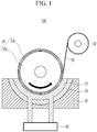
- FIG. 1 is a schematic view illustrating an apparatus of manufacturing an electrolytic copper foil according to an exemplary embodiment of the present invention
- FIG. 2 is a cross-sectional view of protrusions according to an exemplary embodiment of the present invention
- FIG. 3 is a view for describing an arrangement of protrusions according to an exemplary embodiment of the present invention.
- an apparatus 100 of manufacturing an electrolytic copper foil includes a first rotating drum 10, an electrolytic bath 20 receiving an electrolyte 22 in which the first rotating drum 10 is partially immersed, and a second rotating drum 30.
- the first drum 10 may be a metal, that is, an anode electrode in which copper is precipitated.
- the first rotating drum 10 includes an internal drum 10a and an outer drum 10b.
- the outer drum 10b may have a hollow tube shape and the internal drum 10a may be inserted into the outer drum 10b.
- the internal drum 10a is inserted into the outer drum 10b so that an outer surface of the internal drum 10a is in direct contact with an internal surface of the outer drum 10b.
- the outer drum 10b may be formed by inserting the internal drum 10a into the outer drum 10b after the outer drum 10b is separately formed or by attaching a plate shaped metal to an outer side of the internal drum 10a so as to surround the outer side of the internal drum 10a.
- the outer drum 10b may surround the internal drum 10a while being closely adhered to the internal drum 10a.
- the outer drum 10b may have a thickness at which a roughness may be formed, for example, 1 mm to 50 mm.
- the outer drum 10b has one surface with a roughness pattern and the roughness pattern may be a pattern in which protrusions each have a predetermined shape and are regularly arranged.
- protrusions 12 may have a height at which a pattern is formed in a battery foil and may be arranged with an interval interposed therebetween.
- the protrusion 12 protruding at a height H of 0.5 ⁇ m to 10 ⁇ m from a surface of the outer drum 10b and an interval S between adjacent protrusions may be 5 ⁇ m to 100 ⁇ m.
- a cross section of the protrusion 12 cut in a direction perpendicular to a surface of the internal drum may be a polygonal shape such as a triangular shape and a quadrangle shape or a curved shape such as a hemispherical shape, an oval shape, and a circular shape.
- the protrusion 12 may be formed by various methods. According to a desired shape of the protrusion 12, the protrusion may be formed by selectively using methods, for example, a mechanical polishing method, a buffing method, or the like is used as a method of etching a metal, a deposition method in which non-conductive materials are disposed at a position opposite to a desired pattern on a conductive material, and a partial deposition is performed, a patterning method in which a polymer frame is filled with a metal and the polymer is burned at a high temperature to leave the metal only, and a photolithography method in which a metal thin film is applied on a precision polymer pattern and the polymer is removed to form a metal thin film pattern.
- a mechanical polishing method a buffing method, or the like is used as a method of etching a metal
- a deposition method in which non-conductive materials are disposed at a position opposite to a desired pattern on a conductive material, and a partial deposition is performed
- a corrosion resistance and high strength material which is any one selected from the group consisting of a metal material such as a Ti-based material, a Zr-based material, a Fe-based material, a Ni-based material, or a Pb-based material or a non-metal material such as a C-based material or a Si-based material, or an alloy thereof, or a conductive polymer material, may be used.
- a metal material such as a Ti-based material, a Zr-based material, a Fe-based material, a Ni-based material, or a Pb-based material or a non-metal material such as a C-based material or a Si-based material, or an alloy thereof, or a conductive polymer material.
- the internal drum 10a and the outer drum 10b may be formed of different metals, but is not limited thereto, may be formed of the same metal.
- the electrolytic bath 20 receives the electrolyte 22 to form a copper foil and a counter electrode 24 may be installed in the electrolytic bath 20.
- the counter electrode 24 is installed to face an anode electrode and may be a cathode electrode which is a polarity opposite to the anode electrode.
- the electrolyte 22 may be filled to be in contact with a lower surface of the first rotating drum 10 and it is preferable that the electrolyte is filled to a height at which a contact area with the lower surface of the first rotating drum is the maximum.
- the counter electrode 24 may be formed along an outer circumferential surface of the first rotating drum 10 having a circular transversal cross section and may have a hemispherical transversal cross section in a form surrounding a lower portion of the first rotating drum 10.
- the counter electrode 24 is positioned to be spaced apart from the first rotating drum 10 by a predetermined distance and the electrolyte 22 may flow therebetween.
- the electrolyte 22 may be supplied through a pump 40 installed outside and may be circulated.
- the electrolyte 22 may be an electrolyte containing copper sulfate as a main component and the copper foil may be precipitated by a reaction represented by Reaction Formulas (i), (ii), and (iii).
- Reaction Formulas (i), (ii), and (iii). CuSO 4 + 2e - + 2H + ⁇ Cu +H 2 SO 4 (Reaction in rotating drum)
- H 2 O ⁇ 2H + + 1/2O 2 + 2e Reaction in counter electrode
- CuSO 4 + H 2 O ⁇ Cu +H 2 SO 4 + 1/2O 2 Entire reaction
- a thickness of the copper foil may be changed depending on a concentration a current density, and the like of the electrolyte 22, for example, the thickness of the copper foil may be 5 ⁇ m to 100 ⁇ m.
- a copper foil continuously discharged from the first rotating drum 10 is wound around the second rotating drum 30.
- a plurality of rolls may be disposed between the first rotating drum 10 and the second rotating drum 30 so as to control a tension of the copper foil wound around the second rotating drum 30.
- FIG. 4 is a view for describing a method of manufacturing a copper foil using the apparatus of manufacturing an electrolytic copper foil of FIG. 1 .
- the electrolyte 22 containing copper sulfate as a main component is filled in the electrolytic bath 20 and the first rotating drum 10 is installed so that a lower portion of the first rotating drum 10 is partially immersed in the electrolyte of the electrolytic bath 20.
- the copper is continuously precipitated during rotation of the first rotating drum 10, is formed on the surface of the first rotating drum 10 in a thin film form, and is wound around the second rotating drum 30, thereby manufacturing a copper foil roll.
- a specific pattern formed on the surface of the outer drum may be transferred to a surface of the copper foil by using the first rotating drum 10 including the outer drum with the specific pattern.
- the uniform roughness formed on the surface of the copper foil may prevent an adhesive force of the copper foil from being lowered due to the non-uniform surface of the copper foil.
Landscapes
- Chemical & Material Sciences (AREA)
- Engineering & Computer Science (AREA)
- Chemical Kinetics & Catalysis (AREA)
- Electrochemistry (AREA)
- Materials Engineering (AREA)
- Metallurgy (AREA)
- Organic Chemistry (AREA)
- Electrolytic Production Of Metals (AREA)
- Electroplating Methods And Accessories (AREA)
- Cell Electrode Carriers And Collectors (AREA)
Abstract
Description
- This application claims priority to and the benefit of Korean Patent Application No.
10-2017-0148728 - The present invention relates to an apparatus of manufacturing a copper foil. More particularly, the present invention relates to an apparatus of manufacturing an electrolytic copper foil.
- A copper foil may be mainly used as a current collector of a secondary battery or a printed circuit board (PCB).
- Such a copper foil has a small thickness and may be obtained by a method in which a rotating drum is immersed in an electrolyte and copper is precipitated. That is, the rotating drum is immersed in the electrolyte including a copper ion, a current is allowed to flow in a pair of electrodes, and a copper thin film precipitated on a surface of the rotating drum is separated, thereby obtaining a copper foil. In this case, the copper foil may be continuously manufactured by rotation of the rotating drum.
- Meanwhile, the copper foil is generated on the surface of the rotating drum and then separated, and is affected by a surface state of the rotating drum.
- That is, when there are foreign matters on the surface of the rotating drum, a shape of the foreign matter may be transferred onto the surface of the copper foil having a small thickness or grain growth of copper may be non-uniform. Therefore, one surface of the copper foil exposed to air is not in contact with the other surface of the copper foil which is separated from the surface of the rotating drum in a state in which the other surface of the copper foil is in contact with the surface of the rotating drum, thus the surfaces of the copper foil have different shapes from each other.
- When the copper foil has different surface characteristics, the surfaces of the copper foil may have different glosses and an adhesive force difference may occur. In particular, when the copper foil is used as a current collector of a secondary battery, adhesion of an active material formed on the copper foil is lowered, resulting in lowering electrical characteristics of the secondary battery.
- To solve these problems, as a post-processing, a surface etching method, an additional coating method, or the like is performed, but there are increases in cost and process time.
- The present invention has been made in an effort to provide an apparatus of manufacturing an electrolytic copper foil capable of easily manufacturing a copper foil having various shaped surface, if necessary, without an additional post-processing.
- An exemplary embodiment of the present invention provides an apparatus of manufacturing an electrolytic copper foil, including: an electrolytic bath receiving an electrolyte; an internal drum installed so as to be partially immersed in the electrolyte; an outer drum in contact with a surface of the internal drum; a counter electrode positioned in the electrolytic bath and positioned to be spaced apart from the internal drum by a predetermined distance; and a power supply unit electrically connecting between the internal drum and the counter electrode.
- The outer drum may have a hollow tube shape and the internal drum may be inserted into the outer drum.
- The outer drum may have a surface in which a plurality of protrusions are formed, the plurality of protrusion each having a predetermined shape.
- A height of the protrusion may be 0.5 µm to 10 µm.
- The plurality of protrusions may be arranged with a predetermined interval interposed therebetween.
- The interval between the protrusions may be 5 µm to 100 µm.
- A cross section of the protrusion cut in a direction perpendicular to a surface of the internal drum may be a polygonal shape including a triangular shape and a quadrangle shape or a curved shape including a hemispherical shape and a circular shape.
- The outer drum may be formed of a conductive material.
- The conductive material may be any one selected from the group consisting of a Ti-based material, a Zr-based material, a Fe-based material, a Ni-based material, a Pb-based material, a C-based material, or a Si-based material, or an alloy thereof, or a conductive polymer material.
- As in the present invention, when using the outer drum, the copper foil may be manufactured without an additional processing.
- In addition, the copper foil having various surface characteristics may be easily manufactured by diversifying shapes of a roughness formed on the surface of the outer drum.
-
-
FIG. 1 is a schematic view illustrating an apparatus of manufacturing an electrolytic copper foil according to an exemplary embodiment of the present invention. -
FIG. 2 is a cross-sectional view of protrusions according to an exemplary embodiment of the present invention. -
FIG. 3 is a view for describing an arrangement of protrusions according to an exemplary embodiment of the present invention. -
FIG. 4 is a view for describing a method of manufacturing a copper foil using the apparatus of manufacturing an electrolytic copper foil ofFIG. 1 . - Hereinafter, embodiments of the present invention will be described in detail with reference to the accompanying drawings so that those skilled in the art may easily practice the present invention. However, the present invention may be implemented in various different forms and is not limited to exemplary embodiments described herein.
- Portions unrelated to the description will be omitted to obviously describe the present disclosure, and similar portions will be denoted by similar reference numerals throughout the specification. In addition, "first", "second", "third", or the like may be used in order to avoid confusion between components.
- In addition, the size and thickness of each component illustrated are randomly represented for convenience of explanation, but the present invention is not limited thereto.
- Hereinafter, an apparatus of manufacturing an electrolytic copper foil according to the present invention will be described with reference to the accompanying drawings.
-
FIG. 1 is a schematic view illustrating an apparatus of manufacturing an electrolytic copper foil according to an exemplary embodiment of the present invention,FIG. 2 is a cross-sectional view of protrusions according to an exemplary embodiment of the present invention, andFIG. 3 is a view for describing an arrangement of protrusions according to an exemplary embodiment of the present invention. - As illustrated in
FIG. 1 , anapparatus 100 of manufacturing an electrolytic copper foil according to an exemplary embodiment of the present invention includes a first rotatingdrum 10, anelectrolytic bath 20 receiving anelectrolyte 22 in which the first rotatingdrum 10 is partially immersed, and a second rotatingdrum 30. - In the
apparatus 100 of manufacturing an electrolytic copper foil, a metal is precipitated on a surface of an electrode in a thin film form by allowing a current to flow between two electrodes and the precipitated metal is separated from the electrode, thereby obtaining a metal thin film. Thefirst drum 10 may be a metal, that is, an anode electrode in which copper is precipitated. - The first rotating
drum 10 includes aninternal drum 10a and anouter drum 10b. Theouter drum 10b may have a hollow tube shape and theinternal drum 10a may be inserted into theouter drum 10b. In this case, it is preferable that theinternal drum 10a is inserted into theouter drum 10b so that an outer surface of theinternal drum 10a is in direct contact with an internal surface of theouter drum 10b. - Accordingly, the
outer drum 10b may be formed by inserting theinternal drum 10a into theouter drum 10b after theouter drum 10b is separately formed or by attaching a plate shaped metal to an outer side of theinternal drum 10a so as to surround the outer side of theinternal drum 10a. - In this case, the
outer drum 10b may surround theinternal drum 10a while being closely adhered to theinternal drum 10a. Theouter drum 10b may have a thickness at which a roughness may be formed, for example, 1 mm to 50 mm. - Meanwhile, the
outer drum 10b has one surface with a roughness pattern and the roughness pattern may be a pattern in which protrusions each have a predetermined shape and are regularly arranged. - As in
FIG. 2 andFIG. 3 ,protrusions 12 may have a height at which a pattern is formed in a battery foil and may be arranged with an interval interposed therebetween. As an example, theprotrusion 12 protruding at a height H of 0.5 µm to 10 µm from a surface of theouter drum 10b and an interval S between adjacent protrusions may be 5 µm to 100 µm. - A cross section of the
protrusion 12 cut in a direction perpendicular to a surface of the internal drum may be a polygonal shape such as a triangular shape and a quadrangle shape or a curved shape such as a hemispherical shape, an oval shape, and a circular shape. - The
protrusion 12 may be formed by various methods. According to a desired shape of theprotrusion 12, the protrusion may be formed by selectively using methods, for example, a mechanical polishing method, a buffing method, or the like is used as a method of etching a metal, a deposition method in which non-conductive materials are disposed at a position opposite to a desired pattern on a conductive material, and a partial deposition is performed, a patterning method in which a polymer frame is filled with a metal and the polymer is burned at a high temperature to leave the metal only, and a photolithography method in which a metal thin film is applied on a precision polymer pattern and the polymer is removed to form a metal thin film pattern. - Referring to
FIG. 1 , since the first rotatingdrum 10 rotates in a state in which it is immersed in the electrolyte, as a material of the first rotatingdrum 10, a corrosion resistance and high strength material which is any one selected from the group consisting of a metal material such as a Ti-based material, a Zr-based material, a Fe-based material, a Ni-based material, or a Pb-based material or a non-metal material such as a C-based material or a Si-based material, or an alloy thereof, or a conductive polymer material, may be used. In this case, theinternal drum 10a and theouter drum 10b may be formed of different metals, but is not limited thereto, may be formed of the same metal. - The
electrolytic bath 20 receives theelectrolyte 22 to form a copper foil and acounter electrode 24 may be installed in theelectrolytic bath 20. Thecounter electrode 24 is installed to face an anode electrode and may be a cathode electrode which is a polarity opposite to the anode electrode. - The
electrolyte 22 may be filled to be in contact with a lower surface of the first rotatingdrum 10 and it is preferable that the electrolyte is filled to a height at which a contact area with the lower surface of the first rotating drum is the maximum. - The
counter electrode 24 may be formed along an outer circumferential surface of the first rotatingdrum 10 having a circular transversal cross section and may have a hemispherical transversal cross section in a form surrounding a lower portion of the first rotatingdrum 10. Thecounter electrode 24 is positioned to be spaced apart from the first rotatingdrum 10 by a predetermined distance and theelectrolyte 22 may flow therebetween. Theelectrolyte 22 may be supplied through apump 40 installed outside and may be circulated. - The
electrolyte 22 may be an electrolyte containing copper sulfate as a main component and the copper foil may be precipitated by a reaction represented by Reaction Formulas (i), (ii), and (iii).
(i) CuSO4 + 2e- + 2H+ → Cu +H2SO4 (Reaction in rotating drum)
(ii) H2O → 2H+ + 1/2O2 + 2e (Reaction in counter electrode)
(iii) CuSO4 + H2O → Cu +H2SO4 + 1/2O2 (Entire reaction)
- A thickness of the copper foil may be changed depending on a concentration a current density, and the like of the
electrolyte 22, for example, the thickness of the copper foil may be 5 µm to 100 µm. - A copper foil continuously discharged from the first
rotating drum 10 is wound around the secondrotating drum 30. A plurality of rolls (not illustrated) may be disposed between the firstrotating drum 10 and the secondrotating drum 30 so as to control a tension of the copper foil wound around the secondrotating drum 30. - When the apparatus of manufacturing an electrolytic copper foil described above is used, it is possible to manufacture a
copper foil 50 having a surface with a roughness. -
FIG. 4 is a view for describing a method of manufacturing a copper foil using the apparatus of manufacturing an electrolytic copper foil ofFIG. 1 . - Referring to
FIG. 4 , theelectrolyte 22 containing copper sulfate as a main component is filled in theelectrolytic bath 20 and the firstrotating drum 10 is installed so that a lower portion of the firstrotating drum 10 is partially immersed in the electrolyte of theelectrolytic bath 20. - In addition, when the first
rotating drum 10 and thecounter electrode 24 are electrically connected to each other and a current is allowed to flow therebetween through apower supply unit 1000, copper is precipitated on the surface of the firstrotating drum 10 by the reaction represented by Reaction Formulas described above. - The copper is continuously precipitated during rotation of the first
rotating drum 10, is formed on the surface of the firstrotating drum 10 in a thin film form, and is wound around the secondrotating drum 30, thereby manufacturing a copper foil roll. - As in the above-described exemplary embodiment, a specific pattern formed on the surface of the outer drum may be transferred to a surface of the copper foil by using the first
rotating drum 10 including the outer drum with the specific pattern. - Since such a roughness is uniformly formed on the surface of the copper foil, it is possible to prevent a surface of a conventional drum from being non-uniform due to transfer of a polishing mark. Accordingly, there are no additional processes for treating a surface of the copper foil.
- Further, the uniform roughness formed on the surface of the copper foil may prevent an adhesive force of the copper foil from being lowered due to the non-uniform surface of the copper foil.
- Therefore, it is possible to easily manufacture a copper foil in view of various characteristics using an outer drum having protrusions whose arrangement and shape are deformed depending on the desired adhesiveness and gloss of a copper foil.
-
- 10: first rotating drum
- 10a: internal drum
- 10b: outer drum
- 20: electrolytic bath
- 30: second rotating drum
- 40: pump
- 50: copper foil
Claims (9)
the outer drum has a hollow tube shape and the internal drum is inserted into the outer drum.
the outer drum has a surface in which a plurality of protrusions are formed, the plurality of protrusion each having a predetermined shape.
a height of the protrusion is 0.5 µm to 10 µm.
the plurality of protrusions are arranged with a predetermined interval interposed therebetween.
the interval between the protrusions is 5 µm to 100 µm.
a cross section of the protrusion cut in a direction perpendicular to a surface of the internal drum is a polygonal shape including a triangular shape and a quadrangle shape or a curved shape including a hemispherical shape.
the outer drum is formed of a conductive material.
the conductive material is any one selected from the group consisting of a Ti-based material, a Zr-based material, a Fe-based material, a Ni-based material, a Pb-based material, a C-based material, or a Si-based material, or an alloy thereof, or a conductive polymer material.
Applications Claiming Priority (2)
| Application Number | Priority Date | Filing Date | Title |
|---|---|---|---|
| KR1020170148728A KR102273727B1 (en) | 2017-11-09 | 2017-11-09 | Manufacturing apparatus of electrolytic copper foil |
| PCT/KR2018/013468 WO2019093758A1 (en) | 2017-11-09 | 2018-11-07 | Apparatus for manufacturing electrolytic copper foil |
Publications (2)
| Publication Number | Publication Date |
|---|---|
| EP3623502A1 true EP3623502A1 (en) | 2020-03-18 |
| EP3623502A4 EP3623502A4 (en) | 2020-05-06 |
Family
ID=66437968
Family Applications (1)
| Application Number | Title | Priority Date | Filing Date |
|---|---|---|---|
| EP18876896.4A Pending EP3623502A4 (en) | 2017-11-09 | 2018-11-07 | APPARATUS FOR MANUFACTURING ELECTROLYTIC COPPER SHEET |
Country Status (6)
| Country | Link |
|---|---|
| US (1) | US11492717B2 (en) |
| EP (1) | EP3623502A4 (en) |
| JP (1) | JP7258309B2 (en) |
| KR (1) | KR102273727B1 (en) |
| CN (1) | CN110785515A (en) |
| WO (1) | WO2019093758A1 (en) |
Families Citing this family (5)
| Publication number | Priority date | Publication date | Assignee | Title |
|---|---|---|---|---|
| KR102463038B1 (en) | 2021-01-11 | 2022-11-03 | 세일정기 (주) | Manufacturing apparatus of electrolytic copper foil |
| KR102548837B1 (en) * | 2021-04-14 | 2023-06-28 | 주식회사 웨스코일렉트로드 | An insoluble anode assembly for manufacturing an electrolytic metal foil |
| KR102515268B1 (en) | 2021-04-26 | 2023-03-29 | 주식회사 다이브 | The Apparatus for Electroforming Metal Foils |
| KR20230082190A (en) | 2021-12-01 | 2023-06-08 | 에이티엑스 주식회사 | Apparatus for Manufacturing Copper Foil |
| KR102565937B1 (en) * | 2022-06-17 | 2023-08-16 | 에스케이넥실리스 주식회사 | Positive Electrode Plate for Apparatus for Manufacturing Copper Foil and Apparatus for Manufacturing Copper Foil |
Family Cites Families (25)
| Publication number | Priority date | Publication date | Assignee | Title |
|---|---|---|---|---|
| US3654115A (en) * | 1968-12-30 | 1972-04-04 | Texas Instruments Inc | Manufacture of perforated metal foil |
| JPH03180482A (en) * | 1989-12-08 | 1991-08-06 | Furukawa Saakitsuto Fuoiru Kk | Electrodeposition drum |
| JP2985012B2 (en) * | 1990-08-21 | 1999-11-29 | 日本ステンレス工材株式会社 | Manufacturing method of electrodeposition drum |
| US6036826A (en) * | 1996-11-22 | 2000-03-14 | Nitto Stainless Steel Kozai Co., Ltd. | Titanium electrodeposition drum |
| JPH108286A (en) * | 1996-06-25 | 1998-01-13 | Naikai Aakit:Kk | Electroplated drum |
| JP3076565B2 (en) * | 1998-08-03 | 2000-08-14 | 住友特殊金属株式会社 | Apparatus and method for producing metal foil and metal foil pieces |
| LU90640B1 (en) | 2000-09-18 | 2002-05-23 | Circuit Foil Luxembourg Trading Sarl | Method for electroplating a strip of foam |
| JP2002184411A (en) * | 2000-12-15 | 2002-06-28 | Sumitomo Electric Ind Ltd | Negative electrode current collector for non-aqueous battery, method for producing the same, and negative electrode for non-aqueous battery |
| JP4441642B2 (en) | 2000-12-27 | 2010-03-31 | 三井金属鉱業株式会社 | Titanium cathode electrode for producing electrolytic copper foil, rotating cathode drum using the titanium cathode electrode, method for producing titanium material used for titanium cathode electrode, and method for correcting titanium material for titanium cathode electrode |
| JP4352623B2 (en) * | 2001-03-09 | 2009-10-28 | パナソニック株式会社 | Method for producing nickel foil for secondary battery current collector |
| JP4719375B2 (en) * | 2001-05-11 | 2011-07-06 | 株式会社ナイカイアーキット | High speed electrodeposition drum and its manufacturing method |
| JP2003049292A (en) * | 2001-08-06 | 2003-02-21 | Nippon Stainless Kozai Kk | Electroplated drum |
| US7767126B2 (en) | 2005-08-22 | 2010-08-03 | Sipix Imaging, Inc. | Embossing assembly and methods of preparation |
| TW200738913A (en) | 2006-03-10 | 2007-10-16 | Mitsui Mining & Smelting Co | Surface treated elctrolytic copper foil and process for producing the same |
| JP2008025025A (en) | 2006-06-22 | 2008-02-07 | Hitachi Chem Co Ltd | Method of manufacturing copper metal having blackened surface, method of manufacturing base material with conductive layer pattern, base material with conductive layer pattern and light transmissive electromagnetic wave shielding member using the same |
| KR100917278B1 (en) * | 2006-12-27 | 2009-09-16 | (주)이모트 | Electroforming method thereof metal current collector plate for secondary battery |
| KR100822092B1 (en) * | 2007-02-07 | 2008-04-15 | 엘에스전선 주식회사 | Copper foil manufacturing method and apparatus for fine circuit, copper foil manufactured using same |
| KR101242374B1 (en) * | 2010-01-19 | 2013-03-14 | 주식회사 티에스엠텍 | Manufacturing Method Of Electrodeposition Rotating Drum |
| KR20130067313A (en) | 2010-11-15 | 2013-06-21 | 제이엑스 닛코 닛세키 킨조쿠 가부시키가이샤 | Electrolytic copper foil |
| KR101265733B1 (en) * | 2010-12-24 | 2013-05-21 | (주)이모트 | Apparatus for manufacturing patterned reproduction by the method of contineous electroforming |
| JP5680491B2 (en) * | 2011-06-22 | 2015-03-04 | 住友電気工業株式会社 | Drum electrode and manufacturing method thereof |
| CN103460462A (en) | 2011-06-28 | 2013-12-18 | 古河电气工业株式会社 | Lithium ion secondary cell, current collector constituting negative electrode of secondary cell, and electrolytic copper foil constituting negative-electrode current collector |
| WO2013030871A1 (en) * | 2011-08-30 | 2013-03-07 | 西工業株式会社 | Holed foil electrolytic precipitation device |
| KR20140078883A (en) | 2012-12-18 | 2014-06-26 | 주식회사 엘지화학 | Method of Manufacturing Electrolytic Copper Foil for Current Collector of Secondary Battery |
| CN106544703A (en) * | 2016-08-10 | 2017-03-29 | 姚晓宁 | Perforation Copper Foil foil machine and its production technology |
-
2017
- 2017-11-09 KR KR1020170148728A patent/KR102273727B1/en active Active
-
2018
- 2018-11-07 US US16/619,318 patent/US11492717B2/en active Active
- 2018-11-07 JP JP2019565202A patent/JP7258309B2/en active Active
- 2018-11-07 CN CN201880041068.0A patent/CN110785515A/en active Pending
- 2018-11-07 EP EP18876896.4A patent/EP3623502A4/en active Pending
- 2018-11-07 WO PCT/KR2018/013468 patent/WO2019093758A1/en not_active Ceased
Also Published As
| Publication number | Publication date |
|---|---|
| US11492717B2 (en) | 2022-11-08 |
| JP2020521055A (en) | 2020-07-16 |
| CN110785515A (en) | 2020-02-11 |
| JP7258309B2 (en) | 2023-04-17 |
| KR102273727B1 (en) | 2021-07-05 |
| US20200095697A1 (en) | 2020-03-26 |
| WO2019093758A1 (en) | 2019-05-16 |
| EP3623502A4 (en) | 2020-05-06 |
| KR20190052895A (en) | 2019-05-17 |
Similar Documents
| Publication | Publication Date | Title |
|---|---|---|
| US11492717B2 (en) | Manufacturing apparatus of electrolytic copper foil | |
| EP2641999A1 (en) | Electrolytic copper foil | |
| EP0458863B1 (en) | Method and apparatus for manufacturing interconnects with fine lines and spacing | |
| KR101377210B1 (en) | Manufacturing method of porous thin film using electroplating | |
| JP2008274417A (en) | Laminated copper foil and method of manufacturing the same | |
| JP2012107266A (en) | Method and apparatus for manufacturing electrolytic copper foil | |
| US6942781B2 (en) | Method for electroplating a strip of foam | |
| JP2011127172A (en) | Plating device and method of fabricating wiring circuit board | |
| CN108122691B (en) | Lithium ion capacitor current collector foil and manufacturing method thereof | |
| JP6721547B2 (en) | Electrolytic copper foil having high tensile strength, electrode including the same, secondary battery including the same, and manufacturing method thereof | |
| JP3416620B2 (en) | Electrolytic copper foil manufacturing apparatus and electrolytic copper foil manufacturing method | |
| US3729389A (en) | Method of electroplating discrete conductive regions | |
| KR101630980B1 (en) | Apparatus for continuous electroforming | |
| JP3661657B2 (en) | Electroplating method and electroplating apparatus | |
| JP2009087561A (en) | Copper foil for lithium secondary cell and its manufacturing method | |
| KR100750314B1 (en) | Mesh type cathode drum for precision pole and manufacturing method thereof | |
| JP2005008972A (en) | Copper foil surface roughening method and surface roughening apparatus | |
| KR100762050B1 (en) | Electrolyte supply means and electrolytic copper foil manufacturing apparatus having the same | |
| KR20180002006A (en) | Producing method the electroforming sheet and electroforming device | |
| KR102301331B1 (en) | Producing method of mask | |
| JP2002097591A (en) | Manufacturing method of metal powder | |
| JPH0156153B2 (en) | ||
| KR100727270B1 (en) | Plating electrode structure for manufacturing printed circuit board and electrolytic plating apparatus having same | |
| WO2025032588A1 (en) | Processes and systems for subtractive and additive manufacturing of patterned foils | |
| KR20250150252A (en) | Anode electrode and manufacturing apparatus of electrolytic copper foil using the same |
Legal Events
| Date | Code | Title | Description |
|---|---|---|---|
| STAA | Information on the status of an ep patent application or granted ep patent |
Free format text: STATUS: THE INTERNATIONAL PUBLICATION HAS BEEN MADE |
|
| PUAI | Public reference made under article 153(3) epc to a published international application that has entered the european phase |
Free format text: ORIGINAL CODE: 0009012 |
|
| STAA | Information on the status of an ep patent application or granted ep patent |
Free format text: STATUS: REQUEST FOR EXAMINATION WAS MADE |
|
| 17P | Request for examination filed |
Effective date: 20191213 |
|
| AK | Designated contracting states |
Kind code of ref document: A1 Designated state(s): AL AT BE BG CH CY CZ DE DK EE ES FI FR GB GR HR HU IE IS IT LI LT LU LV MC MK MT NL NO PL PT RO RS SE SI SK SM TR |
|
| AX | Request for extension of the european patent |
Extension state: BA ME |
|
| A4 | Supplementary search report drawn up and despatched |
Effective date: 20200403 |
|
| RIC1 | Information provided on ipc code assigned before grant |
Ipc: C25D 1/04 20060101ALI20200330BHEP Ipc: C25D 1/00 20060101AFI20200330BHEP |
|
| DAV | Request for validation of the european patent (deleted) | ||
| DAX | Request for extension of the european patent (deleted) | ||
| RAP1 | Party data changed (applicant data changed or rights of an application transferred) |
Owner name: LG ENERGY SOLUTION LTD. |
|
| RAP3 | Party data changed (applicant data changed or rights of an application transferred) |
Owner name: LG ENERGY SOLUTION, LTD. |
|
| STAA | Information on the status of an ep patent application or granted ep patent |
Free format text: STATUS: EXAMINATION IS IN PROGRESS |
|
| 17Q | First examination report despatched |
Effective date: 20240213 |