EP3621782B1 - Form- und füllventil - Google Patents
Form- und füllventil Download PDFInfo
- Publication number
- EP3621782B1 EP3621782B1 EP19749224.2A EP19749224A EP3621782B1 EP 3621782 B1 EP3621782 B1 EP 3621782B1 EP 19749224 A EP19749224 A EP 19749224A EP 3621782 B1 EP3621782 B1 EP 3621782B1
- Authority
- EP
- European Patent Office
- Prior art keywords
- moulding
- filling
- interior space
- filling valve
- valve according
- Prior art date
- Legal status (The legal status is an assumption and is not a legal conclusion. Google has not performed a legal analysis and makes no representation as to the accuracy of the status listed.)
- Active
Links
Images
Classifications
-
- B—PERFORMING OPERATIONS; TRANSPORTING
- B29—WORKING OF PLASTICS; WORKING OF SUBSTANCES IN A PLASTIC STATE IN GENERAL
- B29C—SHAPING OR JOINING OF PLASTICS; SHAPING OF MATERIAL IN A PLASTIC STATE, NOT OTHERWISE PROVIDED FOR; AFTER-TREATMENT OF THE SHAPED PRODUCTS, e.g. REPAIRING
- B29C49/00—Blow-moulding, i.e. blowing a preform or parison to a desired shape within a mould; Apparatus therefor
- B29C49/42—Component parts, details or accessories; Auxiliary operations
- B29C49/4289—Valve constructions or configurations, e.g. arranged to reduce blowing fluid consumption
-
- B—PERFORMING OPERATIONS; TRANSPORTING
- B29—WORKING OF PLASTICS; WORKING OF SUBSTANCES IN A PLASTIC STATE IN GENERAL
- B29C—SHAPING OR JOINING OF PLASTICS; SHAPING OF MATERIAL IN A PLASTIC STATE, NOT OTHERWISE PROVIDED FOR; AFTER-TREATMENT OF THE SHAPED PRODUCTS, e.g. REPAIRING
- B29C49/00—Blow-moulding, i.e. blowing a preform or parison to a desired shape within a mould; Apparatus therefor
- B29C49/08—Biaxial stretching during blow-moulding
- B29C49/10—Biaxial stretching during blow-moulding using mechanical means for prestretching
- B29C49/12—Stretching rods
- B29C49/121—Stretching rod configuration, e.g. geometry; Stretching rod material
- B29C49/1215—Geometry of the stretching rod, e.g. specific stretching rod end shape
-
- B—PERFORMING OPERATIONS; TRANSPORTING
- B29—WORKING OF PLASTICS; WORKING OF SUBSTANCES IN A PLASTIC STATE IN GENERAL
- B29C—SHAPING OR JOINING OF PLASTICS; SHAPING OF MATERIAL IN A PLASTIC STATE, NOT OTHERWISE PROVIDED FOR; AFTER-TREATMENT OF THE SHAPED PRODUCTS, e.g. REPAIRING
- B29C49/00—Blow-moulding, i.e. blowing a preform or parison to a desired shape within a mould; Apparatus therefor
- B29C49/42—Component parts, details or accessories; Auxiliary operations
- B29C49/58—Blowing means
-
- B—PERFORMING OPERATIONS; TRANSPORTING
- B29—WORKING OF PLASTICS; WORKING OF SUBSTANCES IN A PLASTIC STATE IN GENERAL
- B29C—SHAPING OR JOINING OF PLASTICS; SHAPING OF MATERIAL IN A PLASTIC STATE, NOT OTHERWISE PROVIDED FOR; AFTER-TREATMENT OF THE SHAPED PRODUCTS, e.g. REPAIRING
- B29C49/00—Blow-moulding, i.e. blowing a preform or parison to a desired shape within a mould; Apparatus therefor
- B29C49/02—Combined blow-moulding and manufacture of the preform or the parison
- B29C2049/024—Combined blow-moulding and manufacture of the preform or the parison not using inherent heat of the preform, i.e. 2 step blow moulding
-
- B—PERFORMING OPERATIONS; TRANSPORTING
- B29—WORKING OF PLASTICS; WORKING OF SUBSTANCES IN A PLASTIC STATE IN GENERAL
- B29C—SHAPING OR JOINING OF PLASTICS; SHAPING OF MATERIAL IN A PLASTIC STATE, NOT OTHERWISE PROVIDED FOR; AFTER-TREATMENT OF THE SHAPED PRODUCTS, e.g. REPAIRING
- B29C49/00—Blow-moulding, i.e. blowing a preform or parison to a desired shape within a mould; Apparatus therefor
- B29C49/42—Component parts, details or accessories; Auxiliary operations
- B29C49/46—Component parts, details or accessories; Auxiliary operations characterised by using particular environment or blow fluids other than air
- B29C2049/4602—Blowing fluids
- B29C2049/465—Blowing fluids being incompressible
- B29C2049/4664—Blowing fluids being incompressible staying in the final article
-
- B—PERFORMING OPERATIONS; TRANSPORTING
- B29—WORKING OF PLASTICS; WORKING OF SUBSTANCES IN A PLASTIC STATE IN GENERAL
- B29C—SHAPING OR JOINING OF PLASTICS; SHAPING OF MATERIAL IN A PLASTIC STATE, NOT OTHERWISE PROVIDED FOR; AFTER-TREATMENT OF THE SHAPED PRODUCTS, e.g. REPAIRING
- B29C49/00—Blow-moulding, i.e. blowing a preform or parison to a desired shape within a mould; Apparatus therefor
- B29C49/42—Component parts, details or accessories; Auxiliary operations
- B29C49/58—Blowing means
- B29C2049/5831—Diaphragms or bellows protecting the blowing means against contamination
-
- B—PERFORMING OPERATIONS; TRANSPORTING
- B29—WORKING OF PLASTICS; WORKING OF SUBSTANCES IN A PLASTIC STATE IN GENERAL
- B29C—SHAPING OR JOINING OF PLASTICS; SHAPING OF MATERIAL IN A PLASTIC STATE, NOT OTHERWISE PROVIDED FOR; AFTER-TREATMENT OF THE SHAPED PRODUCTS, e.g. REPAIRING
- B29C49/00—Blow-moulding, i.e. blowing a preform or parison to a desired shape within a mould; Apparatus therefor
- B29C49/42—Component parts, details or accessories; Auxiliary operations
- B29C49/78—Measuring, controlling or regulating
- B29C49/783—Measuring, controlling or regulating blowing pressure
- B29C2049/7831—Measuring, controlling or regulating blowing pressure characterised by pressure values or ranges
-
- B—PERFORMING OPERATIONS; TRANSPORTING
- B29—WORKING OF PLASTICS; WORKING OF SUBSTANCES IN A PLASTIC STATE IN GENERAL
- B29C—SHAPING OR JOINING OF PLASTICS; SHAPING OF MATERIAL IN A PLASTIC STATE, NOT OTHERWISE PROVIDED FOR; AFTER-TREATMENT OF THE SHAPED PRODUCTS, e.g. REPAIRING
- B29C49/00—Blow-moulding, i.e. blowing a preform or parison to a desired shape within a mould; Apparatus therefor
- B29C49/42—Component parts, details or accessories; Auxiliary operations
- B29C49/42378—Handling malfunction
- B29C49/4238—Ejecting defective preforms or products
-
- B—PERFORMING OPERATIONS; TRANSPORTING
- B29—WORKING OF PLASTICS; WORKING OF SUBSTANCES IN A PLASTIC STATE IN GENERAL
- B29C—SHAPING OR JOINING OF PLASTICS; SHAPING OF MATERIAL IN A PLASTIC STATE, NOT OTHERWISE PROVIDED FOR; AFTER-TREATMENT OF THE SHAPED PRODUCTS, e.g. REPAIRING
- B29C49/00—Blow-moulding, i.e. blowing a preform or parison to a desired shape within a mould; Apparatus therefor
- B29C49/42—Component parts, details or accessories; Auxiliary operations
- B29C49/42403—Purging or cleaning the blow-moulding apparatus
-
- B—PERFORMING OPERATIONS; TRANSPORTING
- B29—WORKING OF PLASTICS; WORKING OF SUBSTANCES IN A PLASTIC STATE IN GENERAL
- B29L—INDEXING SCHEME ASSOCIATED WITH SUBCLASS B29C, RELATING TO PARTICULAR ARTICLES
- B29L2031/00—Other particular articles
- B29L2031/712—Containers; Packaging elements or accessories, Packages
- B29L2031/7158—Bottles
Definitions
- the invention relates to a form and fill valve according to the preamble of claim 1.
- Form and fill valves are used in devices for forming and filling containers. As a rule, they are part of a so-called form and fill station, of which several e.g. can be arranged on a work wheel in order to achieve the highest possible processing speeds.
- a container is formed from a preform and the container that is being filled is filled. This is achieved by introducing a liquid filling material at high filling pressure into a thermally conditioned preform.
- the preform is usually arranged in a mold and is expanded by the filling material into the container contour specified by the mold. Usual filling pressures in the form and filling stations are between 10 and 40 bar.
- a generic form and fill valve is from US 2016/0361859 A1 known.
- the valve known from this has an interior space which communicates via a laterally arranged inlet with a source for the pressurized liquid filling material.
- An outlet is provided at the lower end of the valve, via which the filling material can be filled into a preform arranged underneath and sealed at the outlet.
- the outlet is closed by a sealing body between the molding and filling processes, that is to say when no preform is arranged under the outlet.
- This sealing body can be raised by means of a tubular plunger running in the longitudinal direction through the valve in order to open the outlet and lowered in order to close the outlet.
- a stretching rod which can be displaced in the longitudinal direction (vertically) and which can be inserted into the preform during a forming and filling process and which stretches it in the longitudinal direction.
- the hydroforming of the preform into a container is supported with the aid of the stretch rod.
- a flexible annular membrane is therefore provided in the interior, which is sealed on the inside and attached to the plunger and on the outside in a sealed manner on wall areas of the interior.
- This membrane is intended to prevent the filling material flowing sideways into the interior space under pressure from reaching the upper areas of the valve.
- the membrane has to be flexible because it has to compensate for the up and down movement of the valve stem.
- One problem with flexible membranes, however, is that they can only withstand pressure to a limited extent.
- the flexible membrane is supported in all operating positions of the valve stem by areas of the inner wall. When the ram is moved, the membrane practically rolls into a different support position on the inner wall. This ensures that the membrane is supported against the inflowing liquid.
- the object of the invention is to provide an improved form and fill valve.
- the form and fill valve according to the invention has a flexible diaphragm ring arranged in its interior between the valve stem and the inner wall area, i. an annular membrane.
- the membrane thus delimits a lower part of the interior through which the filling material under pressure (10-40 bar) is passed into the preform. Furthermore, the membrane ring delimits an upper part of the interior space which is completely filled with a supporting liquid. The supporting liquid ensures that the membrane ring is supported pressure-balanced over the entire surface, that is, is not loaded by the filling material under filling pressure in the lower part of the interior.
- a non-generic valve with a diaphragm ring, which is supported by a supporting liquid, is from the DE 196 11 664 A1 known.
- This valve is intended to be used in particular in the chemical, biochemical and petrochemical sectors, that is to say in areas far from the field of application of the valve according to the invention, where fast switching times are important, among other things.
- the valve according to the invention has a longitudinally displaceable stretching rod penetrating the membrane ring, and is therefore significantly more complex in terms of construction than the known valve.
- the volume of the supporting liquid filled in is constant.
- the support liquid is filled in before the form and fill valve is put into operation and then left unchanged during operation.
- the diaphragm ring as in the prior art, has the inside opposite the valve stem and the outside opposite the inner wall areas is sealed.
- the membrane is readily able to follow the longitudinal movements of the valve tappet.
- the diaphragm ring will have a pre-formed, slightly concave shape when the plunger is lowered. If the plunger is lifted, the change in space in the area of the supporting liquid is compensated for by deforming the membrane into a convex shape.
- an essential aspect of the invention is that the volume of the supporting liquid remains constant after the initial filling.
- this does not exclude the possibility that, in the event of a loss of support fluid, a corresponding refilling is carried out which restores the originally desired volume.
- it is not necessary to adapt the volume to any different form and filling conditions, in particular changed filling pressures.
- the upper part of the interior is completely filled with an incompressible support fluid.
- the term complete is intended to include that the diaphragm ring is in a largely pressure-balanced situation in all operating positions of the form and fill valve, as stated above. It must therefore be ensured that the membrane is completely supported by the support liquid.
- the support fluid can be any incompressible fluid. It is preferably provided that it is a physiologically harmless liquid.
- Another embodiment of the invention relates to the measurement and setting of the filling pressure.
- the filling pressure is usually specified at the filling material source and checked in the filling material flowing into the valve.
- the measurement in the product is relatively complex, however.
- the embodiment according to the invention therefore provides that a pressure sensor is provided in the upper part of the interior space filled with support fluid.
- the pressure exerted on the membrane by the filling material in the lower part of the interior space, which corresponds to the filling pressure acts on the pressure sensor via the support fluid and can then be measured by the latter. In this way, the filling pressure can be determined in a particularly simple manner and then adjusted if necessary.
- the pressure sensor is advantageously provided on a wall area of the upper part of the interior.
- the membrane encloses a cavity system inside which is connected to a suitable leakage indicator, e.g. connected to a sight glass or a sensor.
- a suitable leakage indicator e.g. connected to a sight glass or a sensor.
- Such a membrane can, for. B. as a double membrane made of e.g. be designed two superposed membrane rings which have spaced areas. Spacers can be provided for spacing the membrane rings apart. If the membrane is damaged, either the liquid to be filled penetrates into the cavity from below or the supporting liquid from above and runs from there to the sensor or another leak indicator device. By appropriate coloring of the supporting liquid, one can further achieve that the position of the damage to the membrane can be recognized relatively quickly.
- a membrane with such features and properties is basically from the DE 196 11 664 A1 known albeit in a different field of application. To avoid repetition, reference is made to this document.
- the membrane can consist of the usual materials that can be used for membranes. It is necessary that the material has the necessary flexibility, is impermeable to liquids and has sufficient load-bearing capacity for the intended use. Examples include polytetrafluoroethylene (PTFE), virgin PTFE, acrylonitrile-butadiene rubber (NBR), composite materials such as polyetheretherketone-PTFE (PEEK-PTFE) and fabric-reinforced sealing materials as well as other sealing and rubber materials.
- PTFE polytetrafluoroethylene
- virgin PTFE virgin PTFE
- NBR acrylonitrile-butadiene rubber
- composite materials such as polyetheretherketone-PTFE (PEEK-PTFE) and fabric-reinforced sealing materials as well as other sealing and rubber materials.
- PEEK-PTFE polyetheretherketone-PTFE
- fabric-reinforced sealing materials as well as other sealing and rubber materials.
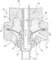
- the figure shows the lower part of a form and fill valve 10 in a sectional view. It can be seen that the valve 10 has an interior space 11 which is divided into a lower part 13 and an upper part 14 by a flexible membrane ring 12 is divided.
- the lower part 13 of the interior 11 has an inlet 15 through which the filling material to be filled can be fed.
- the lower part 13 of the interior 11 also has an outlet 16 which, in the case shown, is closed by a sealing body 17.
- the outlet 16 can be brought into fluid communication with a preform 18.
- the sealing body 17 is raised by means of a tubular valve tappet 19, which is received in the form and fill valve 10 so as to be movable in the longitudinal direction.
- a stretching rod 20 which is arranged longitudinally displaceably in the tubular ram 19 and, as explained above, is intended to support the shaping of the preform 18 in the longitudinal direction, can also be seen.
- the stretching rod 20 is introduced into the preform 18 during the forming and filling process and moved downward until the desired longitudinal expansion is achieved.
- the interior space 11 of the form and fill valve 10 is divided into an upper part 12 and a lower part 13 by a membrane ring 12.
- the task of the membrane ring 12 is to prevent the filling material flowing into the lower part 13 of the interior 11 of the form and fill valve 10 from reaching further areas of the valve and contaminating them.
- the membrane ring 12 is fastened on the inside of the valve tappet 19 with a thickened edge area in a circumferential recess 21.
- the membrane ring 12 is again fastened in a circumferential recess 22 in the valve. It goes without saying that the fastening of the membrane ring is sealed both on the inside and on the outside.
- the preform 18 is shaped and filled with a filling material under a filling pressure of between 10 and 40 bar.
- a filling pressure of between 10 and 40 bar.
- the supporting liquid 23 is an incompressible liquid which is preferably physiologically harmless.
- the upper part 12 of the interior space 11 is completely filled with the support fluid 23, so that the membrane ring 12 is supported by the support fluid in all operating situations. in the In the case shown, the outlet 16 is closed by the sealing body 17, ie the valve stem 19 is in a lowered position and the diaphragm ring 12 has a slightly convex shape.
- the membrane ring is preformed with a slightly convex shape.
- a pressure sensor 24 is also provided with which the pressure exerted on the membrane 12 in the lower part 13 of the interior 11 by the filling material can be measured.
- This pressure corresponds to the filling pressure with which the filling material flows into the lower part 13 of the interior or is introduced into the preform 18.
- the pressure on the membrane 12 pressure is passed on directly to the sensor 24 via the support fluid and thus enables a particularly simple measurement of the filling pressure.
- a membrane ring can be provided which is able to indicate a leak. Since such a membrane ring is sufficiently known from the prior art, it is not presented and discussed here.
Landscapes
- Engineering & Computer Science (AREA)
- Manufacturing & Machinery (AREA)
- Mechanical Engineering (AREA)
- Physics & Mathematics (AREA)
- Geometry (AREA)
- Basic Packing Technique (AREA)
Description
- Die Erfindung bezieht sich auf ein Form- und Füllventil nach dem Oberbegriff des Anspruches 1.
- Form- und Füllventile kommen in Vorrichtungen zum Formen und Befüllen von Behältern zum Einsatz. In der Regel sind sie Bestandteil einer sogenannten Form- und Füllstation, von denen mehrere z.B. auf einem Arbeitsrad angeordnet seien können, um möglichst hohe Bearbeitungsgeschwindigkeiten zu erreichen.
- Im Gegensatz zu normalen Füllventilen, mit denen bereits fertige Behälter gefüllt werden, wird mit Form- und Füllventilen gleichzeitig aus einem Vorformling (Preform) ein Behälter geformt und der sich bildende Behälter gefüllt. Erreicht wird dies durch Einleiten eines flüssigen Füllgutes mit hohem Fülldruck in einen thermisch konditionierten Vorformling. Der Vorformling ist in der Regel in einer Form angeordnet und wird durch das Füllgut in die durch die Form vorgegebene Behälterkontur expandiert. Übliche Fülldrücke in Form-und Füllstationen liegen zwischen 10 und 40 bar.
- Der grundsätzliche Aufbau einer Maschine zum Füllen und Formen von Behältern aus Vorformlingen ist aus dem Stand der Technik hinlänglich bekannt. Zur Vermeidung von Wiederholungen wird auf
DE 10201007541 A1 und dort insbesondere auf die Absätze [0028] bis [0065] verwiesen. - Ein gattungsgemäßes Form- und Füllventil ist aus der
US 2016/0361859 A1 bekannt. Das hieraus bekannte Ventil weist einen Innenraum auf, der über einen seitlich angeordneten Einlass mit einer Quelle für das unter Druck stehende flüssige Füllgut kommuniziert. Am unteren Ende des Ventils ist ein Auslass vorgesehen, über den das Füllgut in einen darunter abgedichtet am Auslass angeordneten Preform gefüllt werden kann. Der Auslass ist zwischen den Form- und Füllvorgängen, also wenn kein Preform unter dem Auslass angeordnet ist, durch einen Dichtkörper verschlossen. Dieser Dichtkörper kann mittels eines in Längsrichtung durch das Ventil verlaufenden rohrförmigen Stößels angehoben werden, um den Auslass frei zu geben, und abgesenkt werden, um den Auslass zu verschließen. In dem rohrförmigen Stößel ist weiterhin eine in Längsrichtung (vertikal) verschiebbare Reckstange angeordnet, die während eines Form- und Füllvorganges in den Preform eingeführt werden kann und diesen in Längsrichtung streckt. Mit Hilfe der Reckstange wird die Hydroformung des Preforms zu einem Behälter unterstützt. - Ein Problem besteht darin, dass der Innenraum von Form- und Füllventilen eine Reihe von schwer zugänglichen Bereichen aufweist, z.B. Ecken, Vorsprünge, Befestigungsspalten zwischen zwei aneinander angeordneten Komponenten etc., die schwierig zu reinigen sind. Um ein mikrobiell einwandfreies Abfüllen von Füllgut zu gewährleisten, müssen diese Bereiche aber vor Inbetriebnahme von allen Flüssigkeitsresten gereinigt werden, was einen relativ großen Aufwand darstellt und ein in der Getränkeindustrie angestrebtes "CIP"-Verfahren (Cleaning in place) erschwert bzw. unmöglich macht.
- Bei dem gattungsgemäßen Form- und Füllventil ist daher im Innenraum eine flexible ringförmige Membran vorgesehen, die innenseitig abgedichtet an dem Stößel und außenseitig abgedichtet an Wandbereichen des Innenraums befestigt ist. Diese Membran soll verhindern, dass das seitwärts in den Innenraum unter Druck einströmende Füllgut in obere Bereiche des Ventils gelangt. Die Membran muss dabei flexibel sein, da sie die Auf- und Abbewegung des Ventilstößels kompensieren muss. Ein Problem mit flexiblen Membranen ist jedoch, dass sie nur bedingt druckbelastbar sind. Bei dem gattungsgemäßen Ventil ist daher vorgesehen, dass die flexible Membran in allen Betriebspositionen des Ventilstößels durch Bereiche der Innenwand abgestützt wird. Wenn der Stößel bewegt wird, dann rollt sich die Membran praktisch in eine andere Abstützposition an der Innenwand. So wird sichergestellt, dass die Membran gegenüber der einströmenden Flüssigkeit abgestützt ist.
- Problematisch an dem gattungsgemäßen Form- und Füllventil ist allerdings, dass die Hub- und Senkbewegungen des Ventilstößels, die Membranfläche und ihre Anordnung in dem Innenraum exakt abgestimmt werden müssen, damit die Membran die Abrollbewegung in die jeweils gewünschte abgestützte Position einnehmen kann.
- Aufgabe der Erfindung ist es, ein verbessertes Form- und Füllventil bereitzustellen.
- Gelöst wird die Aufgabe mit einem Form- und Füllventil, das die kennzeichnenden Merkmale des Anspruches 1 aufweist.
- Ähnlich wie im Stand der Technik weist das erfindungsgemäße Form- und Füllventil einen in seinem Innenraum zwischen dem Ventilstößel und dem Innenwandbereich angeordneten flexiblen Membranring, d.h. eine ringförmige Membran auf.
- Erfindungsgemäß ist vorgesehen, dass die Membran damit einen unteren Teil des Innenraumes begrenzt, durch den das unter Druck (10 - 40 Bar) stehende Füllgut in den Preform geleitet wird. Weiterhin begrenzt der Membranring einen oberen Teil des Innenraums, der vollständig mit einer Stützflüssigkeit gefüllt ist. Die Stützflüssigkeit stellt sicher, dass der Membranring vollflächig druckausgeglichen abgestützt ist, also nicht durch das unter Fülldruck stehende, im unteren Teil des Innenraumes befindliche Füllgut belastet wird.
- Ein gattungsfremdes Ventil mit einem Membranring, der durch eine Stützflüssigkeit abgestützt ist, ist aus der
DE 196 11 664 A1 bekannt. Dieses Ventil soll insbesondere im Chemie, Biochemie und Petrochemiebereich eingesetzt werden, also auf Gebieten fernab vom dem Anwendungsgebiet des erfindungsgemäßen Ventils, wo es unter anderem auf schnelle Schaltzeiten ankommt. Außerdem weist das erfindungsgemäße Ventil eine längsverschiebbare, den Membranring durchsetzende Reckstange auf, und ist damit konstruktiv deutlich aufwändiger als das bekannte Ventil. - Bei dem erfindungsgemäßen Ventil ist vorgesehen, dass das Volumen der eingefüllten Stützflüssigkeit konstant ist. Mit anderen Worten, die Stützflüssigkeit wird vor Inbetriebnahme des Form- und Füllventils eingefüllt und dann im Betrieb unverändert gelassen.
- Es versteht sich weiterhin, dass der Membranring wie im Stand der Technik innenseitig gegenüber dem Ventilstößel und außenseitig gegenüber den Innenwandbereichen abgedichtet ist. Auch bei dieser erfindungsgemäßen Lösung ist die Membran ohne weiteres in der Lage, die Längsbewegungen des Ventilstößels mitzumachen.
- In der Regel wird der Membranring im abgesenkten Zustand des Stößels eine vorgeformte leicht konkave Form aufweisen. Wird der Stößel angehoben, so wird die Raumveränderung im Bereich der Stützflüssigkeit dadurch kompensiert, dass sich die Membran in eine konvexe Form verformt.
- Wie oben ausgeführt ist ein wesentlicher Aspekt der Erfindung, dass das Volumen der Stützflüssigkeit nach initialem Einfüllen konstant bleibt. Dies schließt natürlich nicht aus, dass im Falle von Stützflüssigkeitsverlusten eine entsprechende Nachfüllung erfolgt, die das ursprünglich gewünschte Volumen wieder herstellt. Abgesehen davon ist eine Anpassung des Volumens an eventuelle unterschiedliche Form- und Füllbedingungen, insbesondere veränderte Fülldrücke, nicht erforderlich.
- Erfindungsgemäß ist vorgesehen, dass der obere Teil des Innenraumes vollständig mit einer inkompressiblen Stützflüssigkeit gefüllt ist. Der Begriff vollständig soll beinhalten, dass der Membranring wie oben ausgeführt in einer weitgehend druckausgeglichenen Situation in allen Betriebspositionen des Form- und Füllventils ist. Es muss also sichergestellt sein, dass die Membran vollständig durch die Stützflüssigkeit abgestützt wird.
- Bei der Stützflüssigkeit kann es sich um beliebige inkompressible Flüssigkeiten handeln. Vorzugsweise ist vorgesehen, dass es sich um eine physiologisch unbedenkliche Flüssigkeit handelt.
- Eine weitere Ausgestaltung der Erfindung betrifft die Messung und Einstellung des Fülldruckes. Üblicherweise wird der Fülldruck an der Füllgutquelle vorgegeben und im in das Ventil einströmenden Füllgut überprüft. Die Messung im Füllgut ist allerdings relativ aufwändig. Die erfindungsgemäße Ausgestaltung sieht daher vor, dass in dem mit Stützflüssigkeit gefüllten oberen Teil des Innenraums ein Drucksensor vorgesehen ist. Der durch das Füllgut im unteren Teil des Innenraums auf die Membran ausgeübte Druck, der dem Fülldruck entspricht, wirkt über die Stützflüssigkeit auf den Drucksensor, und kann dann von diesem gemessen werden. Auf diese Weise lässt sich in besonders einfacher Weise der Fülldruck ermitteln und dann ggf. justieren.
- Vorteilhafterweise ist der Drucksensor an einem Wandbereich des oberen Teils des Innenraums vorgesehen.
- Unabhängig von der oben erwähnten Tatsache, dass die Membran durch die Stützflüssigkeit weitgehend druckausgeglichen gehalten wird, kann es im Laufe des Betriebes dennoch zu Beschädigungen kommen, die relativ rasch erkannt werden müssen. Bevorzugt ist daher vorgesehen, dass die Membran im Inneren ein Hohlraumsystem einschließt, das mit einer geeigneten Leckageanzeigeeinrichtung, z.B. einem Schauglas oder einem Sensor verbunden ist. Eine solche Membran kann z. B. als Doppelmembran aus z.B. zwei aufeinanderliegenden Membranringen ausgeführt sein, die beabstandete Bereiche aufweisen. Zur Beabstandung der Membranringe können Abstandshalter vorgesehen sein. Wird die Membran beschädigt, so dringt entweder die abzufüllende Flüssigkeit von unten oder die Stützflüssigkeit von oben in den Hohlraum ein und läuft von dort zu dem Sensor bzw. einer sonstigen Leckanzeigeeinrichtung. Durch entsprechende Färbung der Stützflüssigkeit kann man weiterhin erreichen, dass die Position der Beschädigung der Membran relativ rasch erkannt werden kann.
- Eine Membran mit solchen Merkmalen und Eigenschaften ist grundsätzlich aus der
DE 196 11 664 A1 bekannt wenn auch auf einem anderen Anwendungsgebiet. Um Wiederholungen zu vermeiden wird auf diese Schrift verwiesen. - Die Membran kann aus den üblichen Materialien bestehen, die für Membranen verwendet werden können. Erforderlich ist, dass das Material die notwendige Flexibilität besitzt, flüssigkeitsdicht ist und eine ausreichende Belastbarkeit für den vorgesehenen Einsatz besitzt. Beispielhaft seien hier genannt Polytetrafluorethylen (PTFE), virginales PTFE, Acrylnitril-Butadien-Kautschuk (NBR), Verbundwerkstoffe wie Polyetheretherketon-PTFE (PEEK-PTFE) und gewebeverstärkte Dichtungswerkstoffe sowie sonstige Dichtungs- und Gummiwerkstoffe.
- Im Folgenden soll die Erfindung an Hand einer Figur weiter erläutert werden.
- Die Figur zeigt den unteren Teil eines Form- und Füllventiles 10 in einer Schnittdarstellung. Man erkennt, dass das Ventil 10 einen Innenraum 11 aufweist, der durch einen flexiblen Membranring 12 in einen unteren Teil 13 und einen oberen Teil 14 unterteilt wird. Der untere Teil 13 des Innenraums 11 weist einen Zulauf 15 auf, durch den das abzufüllende Füllgut zugeführt werden kann. Der untere Teil 13 des Innenraums 11 weist weiterhin einen Auslass 16 auf, der im gezeigten Fall durch einen Dichtkörper 17 verschlossen ist. Der Auslass 16 kann in Flüssigkeitsverbindung mit einem Preform 18 gebracht werden.
- Im Füllvorgang, d.h. wenn Flüssigkeit aus dem unteren Teil 13 des Innenraums 11 in den Preform 18 fließen soll, wird der Dichtkörper 17 mittels eines rohrförmigen Ventilstößels 19 angehoben, der in dem Form- und Füllventil 10 in Längsrichtung bewegbar aufgenommen ist.
- Weiterhin zu erkennen ist eine in dem rohrförmigen Stößel 19 längsverschiebbar angeordnete Reckstange 20, die wie oben ausgeführt bei der Ausformung des Preforms 18 in Längsrichtung unterstützen soll. Dazu wird die Reckstange 20 während des Form-und Füllvorganges in den Preform 18 eingeführt und nach unten bewegt, bis die gewünschte Längsausdehnung erreicht ist.
- Wie oben bereits ausgeführt, wird der Innenraum 11 des Form- und Füllventiles 10 durch einen Membranring 12 in einen oberen Teil 12 und einem unteren Teil 13 unterteilt. Aufgabe des Membranringes 12 ist zu verhindern, dass in den unteren Teil 13 des Innenraums 11 des Form- und Füllventiles 10 einströmendes Füllgut in weitere Bereiche des Ventils gelangt und diese kontaminiert. Dazu ist der Membranring 12 innenseitig am Ventilstößel 19 mit einem verdickten Randbereich in einer umlaufenden Ausnehmung 21 befestigt. Aussenseitig ist der Membranring 12 wiederum in einer umlaufenden Ausnehmung 22 im Ventil befestigt. Es versteht sich, dass die Befestigung des Membranringes sowohl innenseitig als auch außenseitig abgedichtet ist.
- Wie bereits mehrfach ausgeführt, erfolgt die Formung und Befüllung des Preforms 18 mit einem unter einem Fülldruck zwischen 10 und 40 Bar stehenden Füllgut. Um zu verhindern, dass der im unteren Teil 13 des Innenraums 11 herrschende Druck den Membranring 12 beschädigt, ist weithin vorgesehen, dass der obere Teil 12 mit einer Stützflüssigkeit 23 gefüllt ist. Es handelt sich bei der Stützflüssigkeit 23 um eine inkompressible Flüssigkeit, die vorzugsweise physiologisch unbedenklich ist. Der obere Teil 12 des Innenraums 11 ist vollständig mit der Stützflüssigkeit 23 gefüllt, sodass der Membranring 12 in allen Betriebssituationen durch die Stützflüssigkeit abgestützt wird. Im gezeigten Fall ist der Auslass 16 durch den Dichtkörper 17 verschlossen, d.h. der Ventilstößel 19 ist in einer abgesenkten Position und der Membranring 12 hat eine leicht konvexe Form. Wird jetzt der Auslass geöffnet und in diesem Zusammenhang der Stößel 19 nach oben bewegt, so kommt es zu einer Neuverteilung der Stützflüssigkeit 23 in dem oberen Teil 13 des Innenraums 11 mit der Folge, dass sich die Membran leicht konkav nach unten ausbeult. Es kann im Rahmen der Erfindung vorgesehen sein, dass der Membranring mit einer leicht konvexen Form vorgeformt ist.
- Im oberen Teil 14 des Innenraums 11 ist weiterhin ein Drucksensor 24 vorgesehen, mit dem der auf die Membran 12 im unteren Teil 13 des Innenraums 11 durch das Füllgut ausgeübte Druck gemessen kann. Dieser Druck entspricht dem Fülldruck, mit dem das Füllgut in den unteren Teil 13 des Innenraums einströmt bzw. in den Preform 18 eingeleitet wird. Der Druck auf die Membran 12 Druck wird über die Stützflüssigkeit direkt auf den Sensor 24 weitergeleitet und ermöglicht so eine besonders einfache Messung des Fülldrucks.
- Wie oben bereits erwähnt, kann im Rahmen der Erfindung ein Membranring vorgesehen werden, der in der Lage ist, eine Leckage anzuzeigen. Da ein solcher Membranring hinlänglich aus dem Stand der Technik bekannt ist, wird hier auf eine Darstellung und Diskussion verzichtet.
Claims (8)
- Form- und Füllventil für die gleichzeitige Ausformung eines zuvor thermisch konditionierten Preforms in einen Behälter und die Befüllung des sich bildenden Behälters durch Einleiten eines unter Druck stehenden Füllgutes, mit einem Innenraum, der einen Einlass in Flüssigkeitsverbindung mit einer Quelle für die unter Druck stehende Füllgut und einen in Flüssigkeitsverbindung mit dem Preform bringbaren Auslass aufweist, dem ein Dichtkörper zugeordnet ist, der mittels eines in Längsrichtung durch das Form- und Füllventil verlaufenden und bewegbaren rohrförmigen Stößels zwischen einer Position, in der er den Auslass verschließt und einer Position, in der er den Auslass freigibt, bewegt werden kann, wobei in dem Stößel eine in Längsrichtung bewegbare Reckstange angeordnet ist, die während des Form-und Füllvorgangs in den Preform eingeführt werden kann und dessen Formung in Längsrichtung unterstützt, und wobei in dem Innenraum ein innenseitig den Stößel abgedichtet umgebender flexibler Membranring vorgesehen ist, der außenseitig abgedichtet mit Wandbereichen des Innenraums verbunden ist und der einen unteren Teil des Innenraums, durch den das Füllgut in den Preform fließt, gegenüber den restlichen Ventilbereichen begrenzt, dadurch gekennzeichnet, dass der Membranring (12) mit einem oberen Teil (14) des Innenraums (11) einen Stützhohlraum einschließt, der dauerhaft vollständig mit einer inkompressiblen Stützflüssigkeit (23) gefüllt ist.
- Form- und Füllventil nach Anspruch 1, dadurch gekennzeichnet, dass die Stützflüssigkeit (23) eine physiologisch unbedenkliche Flüssigkeit ist.
- Form- und Füllventil nach Anspruch 1 oder 2, dadurch gekennzeichnet, dass der Membranring (12) aus einem der folgenden Materialien besteht: Polytetrafluorethylen (PTFE), virginales PTFE, Acrylnitril-Butadien-Kautschuk (NBR), Verbundwerkstoffe wie Polyetheretherketon-PTFE (PEEK-PTFE) und gewebeverstärkte Dichtungswerkstoffe sowie sonstige Dichtungs- und Gummiwerkstoffe.
- Form- und Füllventil nach einem der Ansprüche 1-3, dadurch gekennzeichnet, dass im oberen Teil (14) des Innenraums (11) ein Drucksensor (24) vorgesehen ist.
- Form- und Füllventil nach Anspruch 4, dadurch gekennzeichnet, dass der Drucksensor (24) an einem Wandbereich des oberen Teils (14) des Innenraums (11) angeordnet ist.
- Form- und Füllventil nach einem der Ansprüche 1-5, dadurch gekennzeichnet, dass der Membranring einen inneren Hohlraum aufweist, der über Kanäle mit einer Leckageanzeigeeinrichtung verbunden ist, wobei der Membranring insbesondere als Doppelmembran ausgeführt ist, insbesondere als zwei aufeinanderliegende Membranringe mit zueinander beabstandeten Bereichen, wobei zur Ausbildung der Beabstandung zwischen den aufeinanderliegenden Membranringen Abstandshalter angeordnet sind.
- Form- und Füllventil nach Anspruch 6, dadurch gekennzeichnet, dass die Leckageanzeigeeinrichtung ein Schauglas oder ein Sensor ist.
- Form- und Füllventil nach Anspruch 7, dadurch gekennzeichnet, dass die Leckageanzeigeeinrichtung ein Schauglas ist und die Stützflüssigkeit eine von dem abzufüllenden Füllgut abweichende Einfärbung aufweist.
Applications Claiming Priority (2)
| Application Number | Priority Date | Filing Date | Title |
|---|---|---|---|
| DE102018118237.6A DE102018118237A1 (de) | 2018-07-27 | 2018-07-27 | Form- und Füllventil |
| PCT/EP2019/069248 WO2020020724A1 (de) | 2018-07-27 | 2019-07-17 | Form- und füllventil |
Publications (2)
| Publication Number | Publication Date |
|---|---|
| EP3621782A1 EP3621782A1 (de) | 2020-03-18 |
| EP3621782B1 true EP3621782B1 (de) | 2020-12-30 |
Family
ID=67539423
Family Applications (1)
| Application Number | Title | Priority Date | Filing Date |
|---|---|---|---|
| EP19749224.2A Active EP3621782B1 (de) | 2018-07-27 | 2019-07-17 | Form- und füllventil |
Country Status (3)
| Country | Link |
|---|---|
| EP (1) | EP3621782B1 (de) |
| DE (1) | DE102018118237A1 (de) |
| WO (1) | WO2020020724A1 (de) |
Family Cites Families (7)
| Publication number | Priority date | Publication date | Assignee | Title |
|---|---|---|---|---|
| US4836236A (en) * | 1987-07-29 | 1989-06-06 | Ladisch Thomas P | Flush sealing tank valve with diaphgram |
| DE29507638U1 (de) * | 1995-05-09 | 1995-07-06 | Arca Regler GmbH, 47918 Tönisvorst | Ventil |
| DE202005014423U1 (de) * | 2005-09-12 | 2006-02-23 | Khs Maschinen- Und Anlagenbau Ag | Füllventil mit drucküberwachtem Leckageraum |
| DE102010007541A1 (de) * | 2009-12-23 | 2011-06-30 | KHS Corpoplast GmbH, 22145 | Verfahren und Vorrichtung zur Herstellung von gefüllten Behältern |
| IT1403517B1 (it) * | 2010-12-22 | 2013-10-31 | Azionaria Costruzioni Acma Spa | Dispositivo erogatore di una macchina riempitrice di prodotti liquidi |
| EP2913173A1 (de) * | 2014-02-26 | 2015-09-02 | Discma AG | Injektionsvorrichtung mit mindestens einer flexiblen Membran |
| DE102014017871A1 (de) * | 2014-12-04 | 2016-06-09 | Khs Corpoplast Gmbh | Reckstange für den Form-und Füllkopf einer Maschine zum Formen und Füllen von Behältern aus Vorformlingen |
-
2018
- 2018-07-27 DE DE102018118237.6A patent/DE102018118237A1/de not_active Withdrawn
-
2019
- 2019-07-17 EP EP19749224.2A patent/EP3621782B1/de active Active
- 2019-07-17 WO PCT/EP2019/069248 patent/WO2020020724A1/de not_active Ceased
Non-Patent Citations (1)
| Title |
|---|
| None * |
Also Published As
| Publication number | Publication date |
|---|---|
| WO2020020724A1 (de) | 2020-01-30 |
| DE102018118237A1 (de) | 2020-01-30 |
| EP3621782A1 (de) | 2020-03-18 |
Similar Documents
| Publication | Publication Date | Title |
|---|---|---|
| DE102012211926B4 (de) | Ventil umfassend Ventilstempel und Ventilgehäuse sowie ein Füller | |
| EP2788275B1 (de) | Füllelement mit einem trinox-rohr | |
| DE102013101419B4 (de) | Füllelement sowie Füllsystem | |
| EP3356285B1 (de) | Verfahren und behandlungsstation zur behandlung von kegs | |
| DE102007032434A1 (de) | Blasvorrichtung zum Expandieren von Behältnissen | |
| EP0536505B1 (de) | Verfahren und Vorrichtung zur Füllung eines Gefässes mit einer Flüssigkeit | |
| EP2102093B1 (de) | Vorrichtung zum befüllen von flaschen, insbesondere mit stillem wasser | |
| DE1184943B (de) | Vulkanisierpresse fuer Fahrzeugluftreifen | |
| DE102007013096A1 (de) | Vorrichtung zum Behandeln von Behältnissen | |
| WO2016066275A2 (de) | Kolbenanordnung zum pumpen einer flüssigkeit | |
| EP3621782B1 (de) | Form- und füllventil | |
| DE2723171B2 (de) | Abfüllventil und Verfahren zum Betreiben desselben | |
| DE2734251C3 (de) | Vorrichtung zum Einfüllen einer dosierten Fließmittelmenge in eine Verpackung | |
| DE102016124216B3 (de) | Füllelementanordnung sowie Füllmaschine | |
| EP3201119B1 (de) | Vorrichtung und verfahren zum messmittellosen befüllen eines behältnisses | |
| WO2014198413A1 (de) | Ventilaufsatz zum befüllen und entleeren von behältnissen | |
| WO2018137811A1 (de) | Füllsystem zum füllen von behältern mit einem flüssigen füllgut | |
| EP2848577B1 (de) | Vorrichtung zum Dosieren eines Füllprodukts in einen zu befüllenden Behälter | |
| DE102019114956B4 (de) | Vorrichtung zum Herstellen von mit einem flüssigen Füllgut gefüllten Behältern aus Vorformlingen | |
| EP2813462A1 (de) | Vorrichtung und Verfahren zum Befüllen eines Behälters mit einem Füllprodukt | |
| DE2147134B2 (de) | Füllkopf für einen Druckgas- oder Flüssiggasbehälter | |
| DE102008024579B4 (de) | Behälter | |
| DE2657671A1 (de) | Blas- und fuellvorrichtung fuer maschinen zum formen, abfuellen und verschliessen oder verschweissen von hohlkoerpern aus thermoplasten | |
| DE102023124506B3 (de) | Prüfvorrichtung und Verfahren sowie Prüfstation zur Dichtigkeitsprüfung von offenen, nicht befüllten Dosen | |
| EP4615670A1 (de) | Vorrichtung und verfahren zum herstellen eines mit flüssigem füllgut befüllten behälters aus einem thermisch konditionierten vorformling |
Legal Events
| Date | Code | Title | Description |
|---|---|---|---|
| STAA | Information on the status of an ep patent application or granted ep patent |
Free format text: STATUS: UNKNOWN |
|
| STAA | Information on the status of an ep patent application or granted ep patent |
Free format text: STATUS: THE INTERNATIONAL PUBLICATION HAS BEEN MADE |
|
| PUAI | Public reference made under article 153(3) epc to a published international application that has entered the european phase |
Free format text: ORIGINAL CODE: 0009012 |
|
| STAA | Information on the status of an ep patent application or granted ep patent |
Free format text: STATUS: REQUEST FOR EXAMINATION WAS MADE |
|
| 17P | Request for examination filed |
Effective date: 20191212 |
|
| AK | Designated contracting states |
Kind code of ref document: A1 Designated state(s): AL AT BE BG CH CY CZ DE DK EE ES FI FR GB GR HR HU IE IS IT LI LT LU LV MC MK MT NL NO PL PT RO RS SE SI SK SM TR |
|
| AX | Request for extension of the european patent |
Extension state: BA ME |
|
| REG | Reference to a national code |
Ref country code: DE Ref legal event code: R079 Ref document number: 502019000618 Country of ref document: DE Free format text: PREVIOUS MAIN CLASS: B29C0049580000 Ipc: B29C0049420000 |
|
| GRAP | Despatch of communication of intention to grant a patent |
Free format text: ORIGINAL CODE: EPIDOSNIGR1 |
|
| STAA | Information on the status of an ep patent application or granted ep patent |
Free format text: STATUS: GRANT OF PATENT IS INTENDED |
|
| RIC1 | Information provided on ipc code assigned before grant |
Ipc: B29C 49/12 20060101ALI20200629BHEP Ipc: B29C 49/42 20060101AFI20200629BHEP Ipc: B29C 49/58 20060101ALI20200629BHEP Ipc: F16K 41/10 20060101ALI20200629BHEP Ipc: B29C 49/46 20060101ALN20200629BHEP Ipc: B29L 31/00 20060101ALI20200629BHEP Ipc: B67C 3/00 20060101ALI20200629BHEP |
|
| INTG | Intention to grant announced |
Effective date: 20200715 |
|
| GRAS | Grant fee paid |
Free format text: ORIGINAL CODE: EPIDOSNIGR3 |
|
| GRAA | (expected) grant |
Free format text: ORIGINAL CODE: 0009210 |
|
| STAA | Information on the status of an ep patent application or granted ep patent |
Free format text: STATUS: THE PATENT HAS BEEN GRANTED |
|
| AK | Designated contracting states |
Kind code of ref document: B1 Designated state(s): AL AT BE BG CH CY CZ DE DK EE ES FI FR GB GR HR HU IE IS IT LI LT LU LV MC MK MT NL NO PL PT RO RS SE SI SK SM TR |
|
| DAV | Request for validation of the european patent (deleted) | ||
| DAX | Request for extension of the european patent (deleted) | ||
| REG | Reference to a national code |
Ref country code: GB Ref legal event code: FG4D Free format text: NOT ENGLISH |
|
| REG | Reference to a national code |
Ref country code: AT Ref legal event code: REF Ref document number: 1349490 Country of ref document: AT Kind code of ref document: T Effective date: 20210115 |
|
| REG | Reference to a national code |
Ref country code: DE Ref legal event code: R096 Ref document number: 502019000618 Country of ref document: DE |
|
| REG | Reference to a national code |
Ref country code: IE Ref legal event code: FG4D Free format text: LANGUAGE OF EP DOCUMENT: GERMAN |
|
| PG25 | Lapsed in a contracting state [announced via postgrant information from national office to epo] |
Ref country code: RS Free format text: LAPSE BECAUSE OF FAILURE TO SUBMIT A TRANSLATION OF THE DESCRIPTION OR TO PAY THE FEE WITHIN THE PRESCRIBED TIME-LIMIT Effective date: 20201230 Ref country code: FI Free format text: LAPSE BECAUSE OF FAILURE TO SUBMIT A TRANSLATION OF THE DESCRIPTION OR TO PAY THE FEE WITHIN THE PRESCRIBED TIME-LIMIT Effective date: 20201230 Ref country code: GR Free format text: LAPSE BECAUSE OF FAILURE TO SUBMIT A TRANSLATION OF THE DESCRIPTION OR TO PAY THE FEE WITHIN THE PRESCRIBED TIME-LIMIT Effective date: 20210331 Ref country code: NO Free format text: LAPSE BECAUSE OF FAILURE TO SUBMIT A TRANSLATION OF THE DESCRIPTION OR TO PAY THE FEE WITHIN THE PRESCRIBED TIME-LIMIT Effective date: 20210330 |
|
| PG25 | Lapsed in a contracting state [announced via postgrant information from national office to epo] |
Ref country code: BG Free format text: LAPSE BECAUSE OF FAILURE TO SUBMIT A TRANSLATION OF THE DESCRIPTION OR TO PAY THE FEE WITHIN THE PRESCRIBED TIME-LIMIT Effective date: 20210330 Ref country code: SE Free format text: LAPSE BECAUSE OF FAILURE TO SUBMIT A TRANSLATION OF THE DESCRIPTION OR TO PAY THE FEE WITHIN THE PRESCRIBED TIME-LIMIT Effective date: 20201230 Ref country code: LV Free format text: LAPSE BECAUSE OF FAILURE TO SUBMIT A TRANSLATION OF THE DESCRIPTION OR TO PAY THE FEE WITHIN THE PRESCRIBED TIME-LIMIT Effective date: 20201230 |
|
| REG | Reference to a national code |
Ref country code: NL Ref legal event code: MP Effective date: 20201230 |
|
| PG25 | Lapsed in a contracting state [announced via postgrant information from national office to epo] |
Ref country code: HR Free format text: LAPSE BECAUSE OF FAILURE TO SUBMIT A TRANSLATION OF THE DESCRIPTION OR TO PAY THE FEE WITHIN THE PRESCRIBED TIME-LIMIT Effective date: 20201230 |
|
| REG | Reference to a national code |
Ref country code: LT Ref legal event code: MG9D |
|
| PG25 | Lapsed in a contracting state [announced via postgrant information from national office to epo] |
Ref country code: EE Free format text: LAPSE BECAUSE OF FAILURE TO SUBMIT A TRANSLATION OF THE DESCRIPTION OR TO PAY THE FEE WITHIN THE PRESCRIBED TIME-LIMIT Effective date: 20201230 Ref country code: SK Free format text: LAPSE BECAUSE OF FAILURE TO SUBMIT A TRANSLATION OF THE DESCRIPTION OR TO PAY THE FEE WITHIN THE PRESCRIBED TIME-LIMIT Effective date: 20201230 Ref country code: CZ Free format text: LAPSE BECAUSE OF FAILURE TO SUBMIT A TRANSLATION OF THE DESCRIPTION OR TO PAY THE FEE WITHIN THE PRESCRIBED TIME-LIMIT Effective date: 20201230 Ref country code: RO Free format text: LAPSE BECAUSE OF FAILURE TO SUBMIT A TRANSLATION OF THE DESCRIPTION OR TO PAY THE FEE WITHIN THE PRESCRIBED TIME-LIMIT Effective date: 20201230 Ref country code: PT Free format text: LAPSE BECAUSE OF FAILURE TO SUBMIT A TRANSLATION OF THE DESCRIPTION OR TO PAY THE FEE WITHIN THE PRESCRIBED TIME-LIMIT Effective date: 20210430 Ref country code: LT Free format text: LAPSE BECAUSE OF FAILURE TO SUBMIT A TRANSLATION OF THE DESCRIPTION OR TO PAY THE FEE WITHIN THE PRESCRIBED TIME-LIMIT Effective date: 20201230 |
|
| PG25 | Lapsed in a contracting state [announced via postgrant information from national office to epo] |
Ref country code: PL Free format text: LAPSE BECAUSE OF FAILURE TO SUBMIT A TRANSLATION OF THE DESCRIPTION OR TO PAY THE FEE WITHIN THE PRESCRIBED TIME-LIMIT Effective date: 20201230 |
|
| PG25 | Lapsed in a contracting state [announced via postgrant information from national office to epo] |
Ref country code: IS Free format text: LAPSE BECAUSE OF FAILURE TO SUBMIT A TRANSLATION OF THE DESCRIPTION OR TO PAY THE FEE WITHIN THE PRESCRIBED TIME-LIMIT Effective date: 20210430 |
|
| REG | Reference to a national code |
Ref country code: DE Ref legal event code: R097 Ref document number: 502019000618 Country of ref document: DE |
|
| PG25 | Lapsed in a contracting state [announced via postgrant information from national office to epo] |
Ref country code: AL Free format text: LAPSE BECAUSE OF FAILURE TO SUBMIT A TRANSLATION OF THE DESCRIPTION OR TO PAY THE FEE WITHIN THE PRESCRIBED TIME-LIMIT Effective date: 20201230 |
|
| PLBE | No opposition filed within time limit |
Free format text: ORIGINAL CODE: 0009261 |
|
| STAA | Information on the status of an ep patent application or granted ep patent |
Free format text: STATUS: NO OPPOSITION FILED WITHIN TIME LIMIT |
|
| PG25 | Lapsed in a contracting state [announced via postgrant information from national office to epo] |
Ref country code: DK Free format text: LAPSE BECAUSE OF FAILURE TO SUBMIT A TRANSLATION OF THE DESCRIPTION OR TO PAY THE FEE WITHIN THE PRESCRIBED TIME-LIMIT Effective date: 20201230 |
|
| 26N | No opposition filed |
Effective date: 20211001 |
|
| PG25 | Lapsed in a contracting state [announced via postgrant information from national office to epo] |
Ref country code: ES Free format text: LAPSE BECAUSE OF FAILURE TO SUBMIT A TRANSLATION OF THE DESCRIPTION OR TO PAY THE FEE WITHIN THE PRESCRIBED TIME-LIMIT Effective date: 20201230 |
|
| PG25 | Lapsed in a contracting state [announced via postgrant information from national office to epo] |
Ref country code: SI Free format text: LAPSE BECAUSE OF FAILURE TO SUBMIT A TRANSLATION OF THE DESCRIPTION OR TO PAY THE FEE WITHIN THE PRESCRIBED TIME-LIMIT Effective date: 20201230 |
|
| PG25 | Lapsed in a contracting state [announced via postgrant information from national office to epo] |
Ref country code: MC Free format text: LAPSE BECAUSE OF FAILURE TO SUBMIT A TRANSLATION OF THE DESCRIPTION OR TO PAY THE FEE WITHIN THE PRESCRIBED TIME-LIMIT Effective date: 20201230 |
|
| REG | Reference to a national code |
Ref country code: BE Ref legal event code: MM Effective date: 20210731 |
|
| PG25 | Lapsed in a contracting state [announced via postgrant information from national office to epo] |
Ref country code: IS Free format text: LAPSE BECAUSE OF FAILURE TO SUBMIT A TRANSLATION OF THE DESCRIPTION OR TO PAY THE FEE WITHIN THE PRESCRIBED TIME-LIMIT Effective date: 20210430 Ref country code: LU Free format text: LAPSE BECAUSE OF NON-PAYMENT OF DUE FEES Effective date: 20210717 |
|
| PG25 | Lapsed in a contracting state [announced via postgrant information from national office to epo] |
Ref country code: IE Free format text: LAPSE BECAUSE OF NON-PAYMENT OF DUE FEES Effective date: 20210717 Ref country code: BE Free format text: LAPSE BECAUSE OF NON-PAYMENT OF DUE FEES Effective date: 20210731 |
|
| REG | Reference to a national code |
Ref country code: DE Ref legal event code: R081 Ref document number: 502019000618 Country of ref document: DE Owner name: KHS GMBH, DE Free format text: FORMER OWNER: KHS CORPOPLAST GMBH, 22145 HAMBURG, DE Ref country code: DE Ref document number: 502019000618 Ref legal event code: R082 Country of ref document: DE Representative=s name: EISENFUEHR SPEISER PATENTANWAELTE RECHTSANWAEL, DE |
|
| REG | Reference to a national code |
Ref country code: DE Ref legal event code: R082 Ref document number: 502019000618 Country of ref document: DE Representative=s name: EISENFUEHR SPEISER PATENTANWAELTE RECHTSANWAEL, DE |
|
| REG | Reference to a national code |
Ref country code: CH Ref legal event code: PL |
|
| PG25 | Lapsed in a contracting state [announced via postgrant information from national office to epo] |
Ref country code: LI Free format text: LAPSE BECAUSE OF NON-PAYMENT OF DUE FEES Effective date: 20220731 Ref country code: CH Free format text: LAPSE BECAUSE OF NON-PAYMENT OF DUE FEES Effective date: 20220731 |
|
| PG25 | Lapsed in a contracting state [announced via postgrant information from national office to epo] |
Ref country code: NL Free format text: LAPSE BECAUSE OF NON-PAYMENT OF DUE FEES Effective date: 20201230 Ref country code: CY Free format text: LAPSE BECAUSE OF FAILURE TO SUBMIT A TRANSLATION OF THE DESCRIPTION OR TO PAY THE FEE WITHIN THE PRESCRIBED TIME-LIMIT Effective date: 20201230 |
|
| PG25 | Lapsed in a contracting state [announced via postgrant information from national office to epo] |
Ref country code: SM Free format text: LAPSE BECAUSE OF FAILURE TO SUBMIT A TRANSLATION OF THE DESCRIPTION OR TO PAY THE FEE WITHIN THE PRESCRIBED TIME-LIMIT Effective date: 20201230 Ref country code: HU Free format text: LAPSE BECAUSE OF FAILURE TO SUBMIT A TRANSLATION OF THE DESCRIPTION OR TO PAY THE FEE WITHIN THE PRESCRIBED TIME-LIMIT; INVALID AB INITIO Effective date: 20190717 |
|
| GBPC | Gb: european patent ceased through non-payment of renewal fee |
Effective date: 20230717 |
|
| PG25 | Lapsed in a contracting state [announced via postgrant information from national office to epo] |
Ref country code: MK Free format text: LAPSE BECAUSE OF FAILURE TO SUBMIT A TRANSLATION OF THE DESCRIPTION OR TO PAY THE FEE WITHIN THE PRESCRIBED TIME-LIMIT Effective date: 20201230 Ref country code: GB Free format text: LAPSE BECAUSE OF NON-PAYMENT OF DUE FEES Effective date: 20230717 |
|
| PG25 | Lapsed in a contracting state [announced via postgrant information from national office to epo] |
Ref country code: MT Free format text: LAPSE BECAUSE OF FAILURE TO SUBMIT A TRANSLATION OF THE DESCRIPTION OR TO PAY THE FEE WITHIN THE PRESCRIBED TIME-LIMIT Effective date: 20201230 |
|
| REG | Reference to a national code |
Ref country code: AT Ref legal event code: MM01 Ref document number: 1349490 Country of ref document: AT Kind code of ref document: T Effective date: 20240717 |
|
| PGFP | Annual fee paid to national office [announced via postgrant information from national office to epo] |
Ref country code: DE Payment date: 20250722 Year of fee payment: 7 |
|
| PGFP | Annual fee paid to national office [announced via postgrant information from national office to epo] |
Ref country code: IT Payment date: 20250724 Year of fee payment: 7 |
|
| PG25 | Lapsed in a contracting state [announced via postgrant information from national office to epo] |
Ref country code: AT Free format text: LAPSE BECAUSE OF NON-PAYMENT OF DUE FEES Effective date: 20240717 |
|
| PGFP | Annual fee paid to national office [announced via postgrant information from national office to epo] |
Ref country code: FR Payment date: 20250725 Year of fee payment: 7 |
|
| PG25 | Lapsed in a contracting state [announced via postgrant information from national office to epo] |
Ref country code: TR Free format text: LAPSE BECAUSE OF FAILURE TO SUBMIT A TRANSLATION OF THE DESCRIPTION OR TO PAY THE FEE WITHIN THE PRESCRIBED TIME-LIMIT Effective date: 20201230 |
|
| P01 | Opt-out of the competence of the unified patent court (upc) registered |
Free format text: CASE NUMBER: UPC_APP_0014568_3621782/2025 Effective date: 20251125 |
|
| PGFP | Annual fee paid to national office [announced via postgrant information from national office to epo] |
Ref country code: AT Payment date: 20260410 Year of fee payment: 5 |