EP3620128B1 - Multi-port surgical robotic system architecture - Google Patents
Multi-port surgical robotic system architecture Download PDFInfo
- Publication number
- EP3620128B1 EP3620128B1 EP19204702.5A EP19204702A EP3620128B1 EP 3620128 B1 EP3620128 B1 EP 3620128B1 EP 19204702 A EP19204702 A EP 19204702A EP 3620128 B1 EP3620128 B1 EP 3620128B1
- Authority
- EP
- European Patent Office
- Prior art keywords
- link
- joint
- vertical
- linkage
- parallelogram
- Prior art date
- Legal status (The legal status is an assumption and is not a legal conclusion. Google has not performed a legal analysis and makes no representation as to the accuracy of the status listed.)
- Active
Links
- 238000002432 robotic surgery Methods 0.000 claims description 39
- 230000008878 coupling Effects 0.000 claims description 27
- 238000010168 coupling process Methods 0.000 claims description 27
- 238000005859 coupling reaction Methods 0.000 claims description 27
- 238000003780 insertion Methods 0.000 claims description 8
- 230000037431 insertion Effects 0.000 claims description 8
- 238000013519 translation Methods 0.000 claims description 2
- 230000007246 mechanism Effects 0.000 description 20
- 238000001356 surgical procedure Methods 0.000 description 19
- 238000000034 method Methods 0.000 description 17
- 210000000323 shoulder joint Anatomy 0.000 description 14
- 210000003857 wrist joint Anatomy 0.000 description 9
- 210000001503 joint Anatomy 0.000 description 6
- 230000008569 process Effects 0.000 description 6
- 238000003384 imaging method Methods 0.000 description 5
- 230000000712 assembly Effects 0.000 description 3
- 238000000429 assembly Methods 0.000 description 3
- 238000002405 diagnostic procedure Methods 0.000 description 3
- 238000002324 minimally invasive surgery Methods 0.000 description 3
- 210000003815 abdominal wall Anatomy 0.000 description 2
- 230000009286 beneficial effect Effects 0.000 description 2
- 238000004891 communication Methods 0.000 description 2
- 238000010276 construction Methods 0.000 description 2
- 238000010586 diagram Methods 0.000 description 2
- 230000000694 effects Effects 0.000 description 2
- 230000005484 gravity Effects 0.000 description 2
- 210000004247 hand Anatomy 0.000 description 2
- 238000012986 modification Methods 0.000 description 2
- 230000004048 modification Effects 0.000 description 2
- 230000008447 perception Effects 0.000 description 2
- 238000012545 processing Methods 0.000 description 2
- 238000011084 recovery Methods 0.000 description 2
- 230000004044 response Effects 0.000 description 2
- 208000002847 Surgical Wound Diseases 0.000 description 1
- 206010052428 Wound Diseases 0.000 description 1
- 208000027418 Wounds and injury Diseases 0.000 description 1
- 230000004075 alteration Effects 0.000 description 1
- 210000003484 anatomy Anatomy 0.000 description 1
- 230000008859 change Effects 0.000 description 1
- 230000002939 deleterious effect Effects 0.000 description 1
- 239000012636 effector Substances 0.000 description 1
- 238000005516 engineering process Methods 0.000 description 1
- 230000001939 inductive effect Effects 0.000 description 1
- 238000002357 laparoscopic surgery Methods 0.000 description 1
- NJPPVKZQTLUDBO-UHFFFAOYSA-N novaluron Chemical compound C1=C(Cl)C(OC(F)(F)C(OC(F)(F)F)F)=CC=C1NC(=O)NC(=O)C1=C(F)C=CC=C1F NJPPVKZQTLUDBO-UHFFFAOYSA-N 0.000 description 1
- 230000003287 optical effect Effects 0.000 description 1
- 210000000056 organ Anatomy 0.000 description 1
- 230000002980 postoperative effect Effects 0.000 description 1
- 230000035807 sensation Effects 0.000 description 1
- 238000012549 training Methods 0.000 description 1
Images


Classifications
-
- A—HUMAN NECESSITIES
- A61—MEDICAL OR VETERINARY SCIENCE; HYGIENE
- A61B—DIAGNOSIS; SURGERY; IDENTIFICATION
- A61B34/00—Computer-aided surgery; Manipulators or robots specially adapted for use in surgery
- A61B34/30—Surgical robots
-
- A—HUMAN NECESSITIES
- A61—MEDICAL OR VETERINARY SCIENCE; HYGIENE
- A61B—DIAGNOSIS; SURGERY; IDENTIFICATION
- A61B34/00—Computer-aided surgery; Manipulators or robots specially adapted for use in surgery
- A61B34/30—Surgical robots
- A61B34/37—Master-slave robots
-
- A—HUMAN NECESSITIES
- A61—MEDICAL OR VETERINARY SCIENCE; HYGIENE
- A61B—DIAGNOSIS; SURGERY; IDENTIFICATION
- A61B90/00—Instruments, implements or accessories specially adapted for surgery or diagnosis and not covered by any of the groups A61B1/00 - A61B50/00, e.g. for luxation treatment or for protecting wound edges
- A61B90/50—Supports for surgical instruments, e.g. articulated arms
-
- F—MECHANICAL ENGINEERING; LIGHTING; HEATING; WEAPONS; BLASTING
- F16—ENGINEERING ELEMENTS AND UNITS; GENERAL MEASURES FOR PRODUCING AND MAINTAINING EFFECTIVE FUNCTIONING OF MACHINES OR INSTALLATIONS; THERMAL INSULATION IN GENERAL
- F16M—FRAMES, CASINGS OR BEDS OF ENGINES, MACHINES OR APPARATUS, NOT SPECIFIC TO ENGINES, MACHINES OR APPARATUS PROVIDED FOR ELSEWHERE; STANDS; SUPPORTS
- F16M11/00—Stands or trestles as supports for apparatus or articles placed thereon ; Stands for scientific apparatus such as gravitational force meters
- F16M11/20—Undercarriages with or without wheels
- F16M11/2007—Undercarriages with or without wheels comprising means allowing pivoting adjustment
- F16M11/2035—Undercarriages with or without wheels comprising means allowing pivoting adjustment in more than one direction
-
- A—HUMAN NECESSITIES
- A61—MEDICAL OR VETERINARY SCIENCE; HYGIENE
- A61B—DIAGNOSIS; SURGERY; IDENTIFICATION
- A61B17/00—Surgical instruments, devices or methods, e.g. tourniquets
- A61B2017/00477—Coupling
-
- A—HUMAN NECESSITIES
- A61—MEDICAL OR VETERINARY SCIENCE; HYGIENE
- A61B—DIAGNOSIS; SURGERY; IDENTIFICATION
- A61B34/00—Computer-aided surgery; Manipulators or robots specially adapted for use in surgery
- A61B34/30—Surgical robots
- A61B2034/304—Surgical robots including a freely orientable platform, e.g. so called 'Stewart platforms'
-
- A—HUMAN NECESSITIES
- A61—MEDICAL OR VETERINARY SCIENCE; HYGIENE
- A61B—DIAGNOSIS; SURGERY; IDENTIFICATION
- A61B90/00—Instruments, implements or accessories specially adapted for surgery or diagnosis and not covered by any of the groups A61B1/00 - A61B50/00, e.g. for luxation treatment or for protecting wound edges
- A61B90/50—Supports for surgical instruments, e.g. articulated arms
- A61B2090/506—Supports for surgical instruments, e.g. articulated arms using a parallelogram linkage, e.g. panthograph
-
- A—HUMAN NECESSITIES
- A61—MEDICAL OR VETERINARY SCIENCE; HYGIENE
- A61B—DIAGNOSIS; SURGERY; IDENTIFICATION
- A61B34/00—Computer-aided surgery; Manipulators or robots specially adapted for use in surgery
- A61B34/30—Surgical robots
- A61B34/35—Surgical robots for telesurgery
Definitions
- Minimally invasive medical techniques are intended to reduce the amount of extraneous tissue that is damaged during diagnostic or surgical procedures, thereby reducing patient recovery time, discomfort, and deleterious side effects.
- One effect of minimally invasive surgery for example, is reduced post-operative hospital recovery times. Because the average hospital stay for a standard surgery is typically significantly longer than the average stay for an analogous minimally invasive surgery, increased use of minimally invasive techniques could save millions of dollars in hospital costs each year. While many of the surgeries performed each year in the United States could potentially be performed in a minimally invasive manner, only a portion of the current surgeries use these advantageous techniques due to limitations in minimally invasive surgical instruments and the additional surgical training involved in mastering them.
- Minimally invasive robotic surgical or telesurgical systems have been developed to increase a surgeon's dexterity and avoid some of the limitations on traditional minimally invasive techniques.
- the surgeon uses some form of remote control (e.g. , a servomechanism or the like) to manipulate surgical instrument movements, rather than directly holding and moving the instruments by hand.
- the surgeon can be provided with an image of the surgical site at a surgical workstation. While viewing a two or three dimensional image of the surgical site on a display, the surgeon performs the surgical procedures on the patient by manipulating master control devices, which in turn control motion of the servo-mechanically operated instruments.
- the servomechanism used for telesurgery will often accept input from two master controllers (one for each of the surgeon's hands) and may include two or more robotic arms on each of which a surgical instrument is mounted. Operative communication between master controllers and associated robotic arm and instrument assemblies is typically achieved through a control system.
- the control system typically includes at least one processor that relays input commands from the master controllers to the associated robotic arm and instrument assemblies and back from the instrument and arm assemblies to the associated master controllers in the case of, for example, force feedback or the like.
- One example of a robotic surgical system is the DA VINCI ® system available from Intuitive Surgical, Inc. of Sunnyvale, Calif.
- the driven linkage or "slave” is often called a robotic surgical manipulator, and exemplary linkage arrangements for use as a robotic surgical manipulator during minimally invasive robotic surgery are described in U.S. Pat. Nos. 7,594,912 ; 6,758,843 ; 6,246,200 ; and 5,800,423 .
- These linkages often make use of a parallelogram arrangement to hold an instrument having a shaft.
- Such a manipulator structure can constrain movement of the instrument so that the instrument pivots about a remote center of manipulation positioned in space along the length of the rigid shaft.
- an end effector of the surgical instrument can be positioned safely by moving the proximal end of the shaft using the manipulator linkage without imposing potentially dangerous forces against the abdominal wall.
- Alternative manipulator structures are described, for example, in U.S. Pat. Nos. 7,763,015 ; 6,702,805 ; 6,676,669 ; 5,855,583 ; 5,808,665 ; 5,445,166 ; and 5,184,601 .
- a variety of structural arrangements can also be used to support and position the robotic surgical manipulator and the surgical instrument at the surgical site during robotic surgery.
- Supporting linkage mechanisms sometimes referred to as set-up joints, or set-up joint arms, are often used to position and align each manipulator with the respective incision point in a patient's body.
- the supporting linkage mechanism facilitates the alignment of a surgical manipulator with a desired surgical incision point and targeted anatomy. Exemplary supporting linkage mechanisms are described in U.S. Pat. Nos. 6,246,200 and 6,788,018 .
- US 2009/163931 discloses a robotic surgery system which comprises a mounting base, a plurality of surgical instruments, and an articulate support assembly. Each instrument is insertable into a patient through an associated minimally invasive aperture to a desired internal surgical site.
- the articulate support assembly movably supports the instruments relative to the base.
- the support generally comprises an orienting platform, a platform linkage movably supporting the orienting platform relative to the base, and a plurality of manipulators mounted to the orienting platform, wherein each manipulator movably supports an associated instrument.
- WO 2010/068005 discloses a bed mount surgical robot, for performing a surgical procedure on a patient lying on an operating bed using a surgical instrument mounted on an end portion of a robot arm, that can include: a main unit joined to the operating bed, a support arm rotatably joined to the main unit, and one or more robot arms rotatably joined to the support arm. Since multiple robot arms may be joined to a support arm, which itself may be joined to a main unit mounted on the operating bed, the surgical slave robot can have a slim, compact form as well as greater stability. Also, as the robot arms may be mounted onto the bed, the relative positions of the robot arms with respect to the bed can be accurately identified without having to separately input the position information of the bed when installing the robot arms.
- US 2010/262162 discloses a medical manipulator that has a connecting block, a joint shaft, and a distal-end working unit.
- the distal-end working unit has a gripper, a pitch axis, and a yaw axis which serve as distal-end joints for changing the orientation of the gripper.
- the gripper, the pitch axis, and the yaw axis are operated by rotors around which wires are wound.
- the joint shaft has a first intermediate joint and a second intermediate joint which are bendable by the wires which are moved back and forth. Since the manipulator can be bent at the first intermediate joint and the second intermediate joint, the joint shaft can appropriately be placed, and the gripper can be adjusted to an appropriate orientation with respect to an organ by being turned around the pitch axis and the yaw axis.
- An improved robotic surgery system includes an orienting platform that is used to support a plurality of set-up linkages, each of which supports an associated surgical instrument manipulator, or manipulators.
- a support linkage is used to movably support the orienting platform.
- One or more of the support linkages can include a reorientation mechanism operable to reposition the manipulator via a motion that maintains an associated remote center of manipulation (RC) in a fixed position, thereby allowing the supported manipulator to be repositioned without the risk of inducing potentially dangerous forces to a patient at an incision location.
- RC remote center of manipulation
- one or more of the support linkages can also include a first link rotationally coupled to the orienting platform, a second link slideably mounted to the first link to slide horizontally relative to the first link, a third link slideably mounted to the second link to slide vertically relative to the second link, and a fourth link rotationally coupled to the third link to rotate relative to the third link about a vertical axis.
- the support linkage can include a movable floor-supported mounting base, and an adjustable linkage coupled to the mounting base and movably supporting the orienting platform.
- the mounting base can also be immovable, for example, by being attached directly to a floor or other fixed structure.
- a robotic surgery system includes an orienting platform, a support linkage movably supporting the orienting platform, a plurality of manipulators, and a plurality of set-up linkages.
- Each of the manipulators can include an instrument holder.
- Each of the manipulators can be configured to support an associated surgical instrument mounted to the instrument holder, insert the associated surgical instrument along an insertion axis into a patient through an associated remote center of manipulation (RC), rotate the instrument holder around a first manipulator axis that intersects the associated RC, and rotate the instrument holder around a second manipulator axis that intersects the associated RC.
- RC remote center of manipulation
- Each of the first and second manipulator axes is transverse to the insertion axis.
- Each of the set-up linkages couples one of the manipulators to the orienting platform and is operable to reposition the associated manipulator relative to the orienting platform and fixedly support the associated manipulator in a selected position relative to the orienting platform.
- Each of the set-up linkages includes a proximal link coupled to the orienting platform and a distal link coupled to the associated manipulator.
- At least one of the set-up linkages includes a reorientation mechanism that when actuated moves the distal link relative to the proximal link through a motion that maintains the associated RC in a fixed position relative to the proximal link.
- the reorientation mechanism includes a tornado rotational joint and a tornado link.
- the tornado link has a tornado link proximal end coupled to the tornado rotational joint and a tornado link distal end coupled to the associated manipulator. Actuation of the tornado rotational joint rotates the tornado link around a tornado axis that intersects the RC and that is not aligned with either of the first and second manipulator axes.
- the tornado link is configured to maintain the associated RC in a fixed position relative to the proximal link for all orientations of the tornado link around the tornado axis.
- At least one of the manipulators is mechanically constrained to maintain a fixed position of the associated RC relative to the distal link during the rotation of the instrument holder around the first manipulator axis and during the rotation of the instrument holder around the second manipulator axis.
- at least one of the manipulators can be mechanically configured to move the instrument holder in response to actuation of a first joint of the manipulator through a first motion that is mechanically limited to rotation around the first manipulator axis and to move the instrument holder in response to actuation of a second joint of the manipulator through a second motion that is mechanically limited to rotation around the second manipulator axis.
- the support linkage includes a movable floor-supported mounting base, a column slideably mounted to the mounting base, a boom base member rotationally coupled to the column through a shoulder joint; and an extendable boom member slideably coupled with the boom base member through a boom joint.
- the column is selectively positionable relative to the mounting base along a first support axis that is vertically oriented.
- the shoulder joint is operable to selectively orient the boom base member relative to the column around a second support axis that is vertically oriented.
- the boom joint is operable to selectively position the extendable boom member relative to the boom base member along a third support axis that is horizontally oriented.
- the orienting platform is rotationally coupled to the extendable boom member.
- a robotic surgery system in another aspect, includes an orienting platform, a support linkage movably supporting the orienting platform, a plurality of manipulators, and a plurality of set-up linkages.
- Each of the manipulators movably supports an associated surgical instrument insertable into a patient.
- Each of the set-up linkages couples one of the manipulators to the orienting platform and is operable to reposition the associated linkage relative to the orienting platform and fixedly support the associated manipulator relative to the orienting platform.
- At least one of the set-up linkages includes a first link, a second link, a third link, and a fourth link.
- the first link has a first link proximal end rotationally coupled to the orienting platform through a first set-up linkage joint operable to selectively orient the first link relative to the orienting platform around a first set-up linkage axis.
- the second link is slideably mounted to the first link through a second set-up linkage joint operable to selectively reposition the second link relative to the first link along a second set-up linkage axis that is horizontally oriented.
- the third link is slideably mounted to the second link through a third set-up linkage joint operable to selectively reposition the third link relative to the second link along a third set-up linkage axis that is vertically oriented.
- the fourth link is rotationally coupled to the third link through a fourth set-up linkage joint operable to selectively orient the fourth link relative to the third link around a fourth set-up linkage axis that is substantially vertically oriented.
- the associated manipulator is distal to and supported by the fourth link.
- At least one of the manipulators can include an instrument holder configured to support the associated surgical instrument. At least one of the manipulators can be configured to insert the associated surgical instrument into the patient through an associated remote center of manipulation (RC), rotate the instrument holder around a first manipulator axis that intersects the associated RC, and rotate the instrument holder around a second manipulator axis that intersects the associated RC.
- the second manipulator axis is transverse to the first manipulator axis.
- At least one of the set-up linkages includes a reorientation mechanism coupled to the fourth link. Actuation of the reorientation mechanism moves the associated manipulator relative to the fourth link through a motion that maintains the associated RC in a fixed position relative to the fourth link.
- the reorientation mechanism includes a tornado rotational joint and a tornado link.
- the tornado link has a tornado link proximal end coupled to the tornado rotational joint and a tornado link distal end coupled to the associated manipulator. Actuation of the tornado rotational joint rotates the tornado link around a tornado axis that intersect the RC and that is not aligned with either of the first and second manipulator axes.
- the tornado link is configured to maintain the associated RC in a fixed position relative to the fourth link for all orientations of the tornado link around the tornado axis.
- a modular manipulator support for use in a robotic surgery system.
- the robotic surgery system includes a plurality of manipulators that include driven links and joints for moving an associated surgical instrument.
- the modular manipulator support includes a movable floor-supported mounting base, a column slideably coupled with the mounting base, a boom base member rotationally coupled to the column through a shoulder joint, an extendable boom member slideably coupled to the boom base member through a boom joint, an orienting platform rotationally coupled to the extendable boom member through a wrist joint, and a plurality of set-up linkages.
- the column is selectively positionable relative to the mounting base along a first support axis that is vertically oriented.
- the shoulder joint is operable to selectively orient the boom base member relative to the column around a second support axis that is vertically oriented.
- the boom joint is operable to selectively position the extendable boom member relative to the boom base member along a third support axis that is horizontally oriented.
- the wrist joint is operable to selectively orient the orienting platform relative to the extendable boom member around a fourth support axis that is vertically oriented.
- Each of the set-up linkages couples one of the manipulators to the orienting platform and is operable to selectively position the associated manipulator relative to the orienting platform and fixedly support the associated manipulator relative to the orienting platform.
- the angular orientation of the shoulder joint is limited to prevent exceeding a predetermined stability limit of the mounting base.
- At least one of the set-up linkages includes a first link, a second link, a third link, and a fourth link.
- the first link has a first link proximal end rotationally coupled to the orienting platform through a first set-up linkage joint operable to selectively orient the first link relative to the orienting platform around a first set-up linkage axis.
- the second link is slideably mounted to the first link through a second set-up linkage joint operable to selectively reposition the second link relative to the first link along a second set-up linkage axis that is horizontally oriented.
- the third link is slideably mounted to the second link through a third set-up linkage joint operable to selectively reposition the third link relative to the second link along a third set-up linkage axis that is vertically oriented.
- the fourth link is rotationally coupled to the third link through a fourth set-up linkage joint operable to selectively orient the fourth link relative to the third link around a fourth set-up linkage axis that is vertically oriented.
- the associated manipulator is distal to and supported by the fourth link.
- the first link is cantilevered from the first set-up linkage joint in a horizontal direction.
- At least one of the set-up linkages includes a reorientation mechanism coupled to and between the fourth link and the associated manipulator. Actuation of the reorientation mechanism moves the associated manipulator relative to the fourth link through a motion that maintains an associated remote center of manipulation (RC) in a fixed position relative to the fourth link.
- RC remote center of manipulation
- the reorientation mechanism includes a tornado rotational joint and a tornado link.
- the tornado link has a tornado link proximal end coupled to the tornado rotational joint and a tornado link distal end coupled to the associated manipulator. Actuation of the tornado rotational joint rotates the tornado link around a tornado axis that intersect the RC and that is not aligned with either of the first and second manipulator axes.
- the tornado link is configured to maintain the associated RC in a fixed position relative to the fourth link for all orientations of the tornado link around the tornado axis.
- FIG. 1 is a plan view illustration of a Minimally Invasive Robotic Surgical (MIRS) system 10, typically used for performing a minimally invasive diagnostic or surgical procedure on a Patient 12 who is lying down on an Operating table 14.
- the system can include a Surgeon's Console 16 for use by a Surgeon 18 during the procedure.
- One or more Assistants 20 may also participate in the procedure.
- the MIRS system 10 can further include a Patient Side Cart 22 (surgical robot) and an Electronics Cart 24.
- the Patient Side Cart 22 can manipulate at least one removably coupled tool assembly 26 (hereinafter simply referred to as a "tool") through a minimally invasive incision in the body of the Patient 12 while the Surgeon 18 views the surgical site through the Console 16.
- An image of the surgical site can be obtained by an endoscope 28, such as a stereoscopic endoscope, which can be manipulated by the Patient Side Cart 22 to orient the endoscope 28.
- the Electronics Cart 24 can be used to process the images of the surgical site for subsequent display to the Surgeon 18 through the Surgeon's Console 16.
- the number of surgical tools 26 used at one time will generally depend on the diagnostic or surgical procedure and the space constraints within the operating room among other factors. If it is necessary to change one or more of the tools 26 being used during a procedure, an Assistant 20 may remove the tool 26 from the Patient Side Cart 22, and replace it with another tool 26 from a tray 30 in the operating room.
- FIG. 2 is a perspective view of the Surgeon's Console 16.
- the Surgeon's Console 16 includes a left eye display 32 and a right eye display 34 for presenting the Surgeon 18 with a coordinated stereo view of the surgical site that enables depth perception.
- the Console 16 further includes one or more input control devices 36, which in turn cause the Patient Side Cart 22 (shown in FIG. 1 ) to manipulate one or more tools.
- the input control devices 36 can provide the same degrees of freedom as their associated tools 26 (shown in FIG.1 ) to provide the Surgeon with telepresence, or the perception that the input control devices 36 are integral with the tools 26 so that the Surgeon has a strong sense of directly controlling the tools 26.
- position, force, and tactile feedback sensors may be employed to transmit position, force, and tactile sensations from the tools 26 back to the Surgeon's hands through the input control devices 36.
- the Surgeon's Console 16 is usually located in the same room as the patient so that the Surgeon may directly monitor the procedure, be physically present if necessary, and speak to an Assistant directly rather than over the telephone or other communication medium. However, the Surgeon can be located in a different room, a completely different building, or other remote location from the Patient allowing for remote surgical procedures.
- FIG. 3 is a perspective view of the Electronics Cart 24.
- the Electronics Cart 24 can be coupled with the endoscope 28 and can include a processor to process captured images for subsequent display, such as to a Surgeon on the Surgeon's Console, or on another suitable display located locally and/or remotely.
- the Electronics Cart 24 can process the captured images to present the Surgeon with coordinated stereo images of the surgical site.
- Such coordination can include alignment between the opposing images and can include adjusting the stereo working distance of the stereoscopic endoscope.
- image processing can include the use of previously determined camera calibration parameters to compensate for imaging errors of the image capture device, such as optical aberrations.
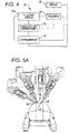
- FIG. 4 diagrammatically illustrates a robotic surgery system 50 (such as MIRS system 10 of FIG. 1 ).
- a Surgeon's Console 52 (such as. Surgeon's Console 16 in FIG.1 ) can be used by a Surgeon to control a Patient Side Cart (Surgical Robot) 54 (such as Patent Side Cart 22 in FIG. 1 ) during a minimally invasive procedure.
- the Patient Side Cart 54 can use an imaging device, such as a stereoscopic endoscope, to capture images of the procedure site and output the captured images to an Electronics Cart 56 (such as the Electronics Cart 24 in FIG. 1 ).
- the Electronics Cart 56 can process the captured images in a variety of ways prior to any subsequent display.
- the Electronics Cart 56 can overlay the captured images with a virtual control interface prior to displaying the combined images to the Surgeon via the Surgeon's Console 52.
- the Patient Side Cart 54 can output the captured images for processing outside the Electronics Cart 56.
- the Patient Side Cart 54 can output the captured images to a processor 58, which can be used to process the captured images.
- the images can also be processed by a combination the Electronics Cart 56 and the processor 58, which can be coupled together to process the captured images jointly, sequentially, and/or combinations thereof.
- One or more separate displays 60 can also be coupled with the processor 58 and/or the Electronics Cart 56 for local and/or remote display of images, such as images of the procedure site, or other related images.
- FIGS. 5A and 5B show a Patient Side Cart 22 and a surgical tool 62, respectively.
- the surgical tool 62 is an example of the surgical tools 26.
- the Patient Side Cart 22 shown provides for the manipulation of three surgical tools 26 and an imaging device 28, such as a stereoscopic endoscope used for the capture of images of the site of the procedure. Manipulation is provided by robotic mechanisms having a number of robotic joints.
- the imaging device 28 and the surgical tools 26 can be positioned and manipulated through incisions in the patient so that a kinematic remote center is maintained at the incision to minimize the size of the incision.
- Images of the surgical site can include images of the distal ends of the surgical tools 26 when they are positioned within the field-of-view of the imaging device 28.
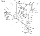
- FIG. 6 is a perspective schematic representation of a robotic surgery system 70, in accordance with many embodiments of the present invention.
- the surgery system 70 includes a mounting base 72, a support linkage 74, an orienting platform 76, a plurality of outer set-up linkages 78 (two shown), a plurality of inner set-up linkages 80 (two shown), and a plurality of surgical instrument manipulators 82.
- Each of the manipulators 82 is operable to selectively articulate a surgical instrument mounted to the manipulator 82 and insertable into a patient along an insertion axis.
- Each of the manipulators 82 is attached to and supported by one of the set-up linkages 78, 80.
- Each of the outer set-up linkages 78 is rotationally coupled to and supported by the orienting platform 76 by a first set-up linkage joint 84.
- Each of the inner set-up linkages 80 is fixedly attached to and supported by the orienting platform 76.
- the orienting platform 76 is rotationally coupled to and supported by the support linkage 74.
- the support linkage 74 is fixedly attached to and supported by the mounting base 72.
- the mounting base 72 is a movable and floor supported, thereby enabling selective repositioning of the overall surgery system 70, for example, within an operating room.
- the mounting base 72 can include a steerable wheel assembly and/or any other suitable support features that provide for both selective repositioning as well as selectively preventing movement of the mounting base 72 from a selected position.
- the mounting base 72 can also have any other suitable configuration, for example, a ceiling mount, fixed floor/pedestal mount, a wall mount, or any other suitable mounting surface.
- the support linkage 74 is operable to selectively position and/or orient the orienting platform 76 relative to the mounting base 72.
- the support linkage 74 includes a column base 86, a translatable column member 88, a shoulder joint 90, a boom base member 92, a boom first stage member 94, a boom second stage member 96, and a wrist joint 98.
- the column base 86 is fixedly attached to the mounting base 72.
- the translatable column member 88 is slideably coupled to the column base 86 for translation relative to column base 86.
- the translatable column member 88 translates relative to the column base 86 along a vertically oriented axis,
- the boom base member 92 is rotationally coupled to the translatable column member 88 by the shoulder joint 90.
- the shoulder joint 90 is operable to selectively orient the boom base member 92 in a horizontal plane relative to the translatable column member 88, which has a fixed angular orientation relative to the column base 86 and the mounting base 72.
- the boom first stage member 94 is selectively translatable relative to the boom base member 92 in a horizontal direction, which in many embodiments is aligned with both the boom base member 92 and the boom first stage member 94.
- the boom second stage member 96 is likewise selectively translatable relative to the boom first stage member 94 in a horizontal direction, which in many embodiments is aligned with the boom first stage member 94 and the boom second stage member 96.
- the support linkage 74 is operable to selectively set the distance between the shoulder joint 90 and the distal end of the boom second stage member 96.
- the wrist joint 98 rotationally couples the distal end of the boom second stage member 96 to the orienting platform 76.
- the wrist joint 98 is operable to selectively set the angular orientation of the orienting platform 76 relative to the mounting base 72.
- Each of the set-up linkages 78, 80 is operable to selectively position and/or orient the associated manipulator 82 relative to the orienting platform 76.
- Each of the set-up linkages 78, 80 includes a set-up linkage base link 100, a set-up linkage extension link 102, a set-up linkage parallelogram linkage portion 104, a set-up linkage vertical link 106, a second set-up linkage joint 108, and a manipulator support link 110.
- each of the set-up linkage base links 100 of the outer set-up linkages 78 can be selectively oriented relative to the orienting platform 76 via the operation of the a first set-up linkage joint 84.
- each of the set-up linkage base links 100 of the inner set-up linkages 80 is fixedly attached to the orienting platform 76.
- Each of the inner set-up linkages 80 can also be rotationally attached to the orienting platform 76 similar to the outer set-up linkages via an additional first set-up linkage joints 84.
- Each of the set-up linkage extension links 102 is translatable relative to the associated set-up linkage base link 100 in a horizontal direction, which in many embodiments is aligned with the associated set-up linkage base link and the set-up linkage extension link 102.
- each of the set-up linkage parallelogram linkage portions 104 configured and operable to selectively translate the set-up linkage vertical link 106 in a vertical direction while keeping the set-up linkage vertical link 106 vertically oriented.
- each of the set-up linkage parallelogram linkage portions 104 includes a first parallelogram joint 112, a coupling link 114, and a second parallelogram 116.
- the first parallelogram joint 112 rotationally couples the coupling link 114 to the set-up linkage extension link 102.
- the second parallelogram joint 116 rotationally couples the set-up linkage vertical link 106 to the coupling link 114.
- the first parallelogram joint 112 is rotationally tied to the second parallelogram joint 116 such that rotation of the coupling link 114 relative to the set-up linkage extension link 102 is matched by a counteracting rotation of the set-up linkage vertical link 106 relative to the coupling link 114 so as to maintain the set-up linkage vertical link 106 vertically oriented while the set-up linkage vertical link 106 is selectively translated vertically.
- the second set-up linkage joint 108 is operable to selectively orient the manipulator support link 110 relative to the set-up linkage vertical link 106, thereby selectively orienting the associated attached manipulator 82 relative to the set-up linkage vertical link 106.
- FIG. 7 is a perspective schematic representation of a robotic surgery system 120, in accordance with many examples. Because the surgery system 120 includes components similar to components of the surgery system 70 of FIG. 6 , the same reference numbers are used for similar components and the corresponding description of the similar components set forth above is applicable to the surgery system 120 and is omitted here to avoid repetition.
- the surgery system 120 includes the mounting base 72, a support linkage 122, an orienting platform 124, a plurality of set-up linkages 126 (four shown), and a plurality of the surgical instrument manipulators 82. Each of the manipulators 82 is operable to selectively articulate a surgical instrument mounted to the manipulator 82 and insertable into a patient along an insertion axis.
- Each of the manipulators 82 is attached to and supported by one of the set-up linkages 126.
- Each of the set-up linkages 126 is rotationally coupled to and supported by the orienting platform 124 by the first set-up linkage joint 84.
- the orienting platform 124 is rotationally coupled to and supported by the support linkage 122.
- the support linkage 122 is fixedly attached to and supported by the mounting base 72.
- the support linkage 122 is operable to selectively position and/or orient the orienting platform 124 relative to the mounting base 72.
- the support linkage 122 includes the column base 86, the translatable column member 88, the shoulder joint 90, the boom base member 92, the boom first stage member 94, and the wrist joint 98.
- the support linkage 122 is operable to selectively set the distance between the shoulder joint 90 and the distal end of the boom first stage member 94.
- the wrist joint 98 rotationally couples the distal end of the boom first stage member 94 to the orienting platform 124.
- the wrist joint 98 is operable to selectively set the angular orientation of the orienting platform 124 relative to the mounting base 72.
- Each of the set-up linkages 126 is operable to selectively position and/or orient the associated manipulator 82 relative to the orienting platform 124.
- Each of the set-up linkages 126 includes the set-up linkage base link 100, the set-up linkage extension link 102, the set-up linkage vertical link 106, the second set-up linkage joint 108, a tornado mechanism support link 128, and a tornado mechanism 130.
- Each of the set-up linkage base links 100 of the set-up linkages 126 can be selectively oriented relative to the orienting platform 124 via the operation of the associated first set-up linkage joint 84.
- Each of the set-up linkage vertical links 106 is selectively translatable in a vertical direction relative to the associated set-up linkage extension link 102.
- the second set-up linkage joint 108 is operable to selectively orient the tornado mechanism support link 128 relative to the set-up linkage vertical link 106
- Each of the tornado mechanisms 130 includes a tornado joint 132, a coupling link 134, and a manipulator support 136.
- the coupling link 134 fixedly couples the manipulator support 136 to the tornado joint 132.
- the tornado joint 130 is operable to rotate the manipulator support 136 relative to the tornado mechanism support link 128 around a tornado axis 136.
- the tornado mechanism 128 is configured to position and orient the manipulator support 134 such that the remote center of manipulation (RC) of the manipulator 82 is intersected by the tornado axis 136. Accordingly, operation of the tornado joint 132 can be used to reorient the associated manipulator 82 relative to the patient without moving the associated remote center of manipulation (RC) relative to the patient.
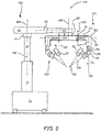
- FIG. 8 is a simplified representation of a robotic surgery system 140, in accordance with many examples, in conformance with the schematic representation of the robotic surgery system 120 of FIG. 7 . Because the surgery system 140 conforms to the robotic surgery system 120 of FIG. 7 , the same reference numbers are used for analogous components and the corresponding description of the analogous components set forth above is applicable to the surgery system 140 and is omitted here to avoid repetition.
- the support linkage 122 is configured to selectively position and orient the orienting platform 124 relative to the mounting base 72 via relative movement between links of the support linkage 122 along multiple set-up structure axes.
- the translatable column member 88 is selectively repositionable relative to the column base 86 along a first set-up structure (SUS) axis 142, which is vertically oriented in many embodiments.
- the shoulder joint 90 is operable to selectively orient the boom base member 92 relative to the translatable column member 88 around a second SUS axis 144, which is vertically oriented in many embodiments.
- the boom first stage member 94 is selectively repositionable relative to the boom base member 92 along a third SUS axis 146, which is horizontally oriented in many embodiments.
- the wrist joint 98 is operable to selectively orient the orienting platform 124 relative to the boom first stage member 94 around a fourth SUS axis 148, which is vertically oriented in many embodiments.
- Each of the set-up linkages 126 is configured to selectively position and orient the associated manipulator 82 relative to the orienting platform 124 via relative movement between links of the set-up linkage 126 along multiple set-up joint (SUJ) axes.
- Each of the first set-up linkage joint 84 is operable to selectively orient the associated set-up linkage base link 100 relative to the orienting platform 124 around a first SUJ axis 150, which in many embodiments is vertically oriented.
- Each of the set-up linkage extension links 102 can be selectively repositioned relative to the associated set-up linkage base link 10 along a second SUJ axis 152, which is horizontally oriented in many embodiments.
- Each of the set-up linkage vertical links 106 can be selectively repositioned relative to the associated set-up linkage extension link 102 along a third SUJ axis 154, which is vertically oriented in many embodiments.
- Each of the second set-up linkage joints 108 is operable to selectively orient the tornado mechanism support link 128 relative to the set-up linkage vertical link 106 around the third SUJ axis 154.
- Each of the tornado joints 132 is operable to rotate the associated manipulator 82 around the associated tornado axis 138.
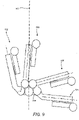
- FIG. 9 illustrates rotational orientation limits of the set-up linkages 126 relative to the orienting platform 124, in accordance with many examples.
- Each of the set-up linkages 126 is shown in a clockwise limit orientation relative to the orienting platform 124.
- a corresponding counter-clockwise limit orientation is represented by a mirror image of FIG. 9 relative to a vertically-oriented mirror plane.
- each of the two inner set-up linkages 126 can be oriented from 5 degrees from a vertical reference 156 in one direction to 75 degrees from the vertical reference 156 in the opposite direction.
- each of the two outer set-up linkages can be oriented from 15 degrees to 95 degrees from the vertical reference 156 in a corresponding direction.
- FIG. 10 shows a center of gravity diagram associated with a rotational limit of a support linkage for a robotic surgery system 160, in accordance with many embodiments.
- a shoulder joint of the support linkage 164 can be configured to limit rotation of the support structure 164 around a set-up structure (SUS) shoulder-joint axis 166 to prevent exceeding a predetermined stability limit of the mounting base.
- SUS set-up structure
Landscapes
- Health & Medical Sciences (AREA)
- Engineering & Computer Science (AREA)
- Life Sciences & Earth Sciences (AREA)
- Surgery (AREA)
- Robotics (AREA)
- Heart & Thoracic Surgery (AREA)
- General Health & Medical Sciences (AREA)
- Biomedical Technology (AREA)
- Nuclear Medicine, Radiotherapy & Molecular Imaging (AREA)
- Medical Informatics (AREA)
- Molecular Biology (AREA)
- Animal Behavior & Ethology (AREA)
- Veterinary Medicine (AREA)
- Public Health (AREA)
- General Engineering & Computer Science (AREA)
- Pathology (AREA)
- Oral & Maxillofacial Surgery (AREA)
- Mechanical Engineering (AREA)
- Manipulator (AREA)
Applications Claiming Priority (3)
| Application Number | Priority Date | Filing Date | Title |
|---|---|---|---|
| US201261654367P | 2012-06-01 | 2012-06-01 | |
| PCT/US2013/043612 WO2013181533A1 (en) | 2012-06-01 | 2013-05-31 | Multi-port surgical robotic system architecture |
| EP13798217.9A EP2854692B1 (en) | 2012-06-01 | 2013-05-31 | Multi-port surgical robotic system architecture |
Related Parent Applications (2)
| Application Number | Title | Priority Date | Filing Date |
|---|---|---|---|
| EP13798217.9A Division-Into EP2854692B1 (en) | 2012-06-01 | 2013-05-31 | Multi-port surgical robotic system architecture |
| EP13798217.9A Division EP2854692B1 (en) | 2012-06-01 | 2013-05-31 | Multi-port surgical robotic system architecture |
Publications (2)
| Publication Number | Publication Date |
|---|---|
| EP3620128A1 EP3620128A1 (en) | 2020-03-11 |
| EP3620128B1 true EP3620128B1 (en) | 2022-07-27 |
Family
ID=49671150
Family Applications (3)
| Application Number | Title | Priority Date | Filing Date |
|---|---|---|---|
| EP19204702.5A Active EP3620128B1 (en) | 2012-06-01 | 2013-05-31 | Multi-port surgical robotic system architecture |
| EP13798217.9A Active EP2854692B1 (en) | 2012-06-01 | 2013-05-31 | Multi-port surgical robotic system architecture |
| EP22174713.2A Pending EP4070755A1 (en) | 2012-06-01 | 2013-05-31 | Multi-port surgical robotic system architecture |
Family Applications After (2)
| Application Number | Title | Priority Date | Filing Date |
|---|---|---|---|
| EP13798217.9A Active EP2854692B1 (en) | 2012-06-01 | 2013-05-31 | Multi-port surgical robotic system architecture |
| EP22174713.2A Pending EP4070755A1 (en) | 2012-06-01 | 2013-05-31 | Multi-port surgical robotic system architecture |
Country Status (6)
| Country | Link |
|---|---|
| US (6) | US9358074B2 (ko) |
| EP (3) | EP3620128B1 (ko) |
| JP (5) | JP6313290B2 (ko) |
| KR (6) | KR102497776B1 (ko) |
| CN (2) | CN108113755B (ko) |
| WO (1) | WO2013181533A1 (ko) |
Families Citing this family (200)
| Publication number | Priority date | Publication date | Assignee | Title |
|---|---|---|---|---|
| US8219178B2 (en) | 2007-02-16 | 2012-07-10 | Catholic Healthcare West | Method and system for performing invasive medical procedures using a surgical robot |
| US10357184B2 (en) | 2012-06-21 | 2019-07-23 | Globus Medical, Inc. | Surgical tool systems and method |
| US10893912B2 (en) | 2006-02-16 | 2021-01-19 | Globus Medical Inc. | Surgical tool systems and methods |
| US10653497B2 (en) | 2006-02-16 | 2020-05-19 | Globus Medical, Inc. | Surgical tool systems and methods |
| US9308050B2 (en) | 2011-04-01 | 2016-04-12 | Ecole Polytechnique Federale De Lausanne (Epfl) | Robotic system and method for spinal and other surgeries |
| US9025358B2 (en) * | 2011-10-13 | 2015-05-05 | Zeno Semiconductor Inc | Semiconductor memory having both volatile and non-volatile functionality comprising resistive change material and method of operating |
| KR102497776B1 (ko) * | 2012-06-01 | 2023-02-09 | 인튜어티브 서지컬 오퍼레이션즈 인코포레이티드 | 멀티포트 수술 로봇 시스템 구조 |
| US11317971B2 (en) | 2012-06-21 | 2022-05-03 | Globus Medical, Inc. | Systems and methods related to robotic guidance in surgery |
| US11116576B2 (en) | 2012-06-21 | 2021-09-14 | Globus Medical Inc. | Dynamic reference arrays and methods of use |
| US11253327B2 (en) | 2012-06-21 | 2022-02-22 | Globus Medical, Inc. | Systems and methods for automatically changing an end-effector on a surgical robot |
| US11395706B2 (en) | 2012-06-21 | 2022-07-26 | Globus Medical Inc. | Surgical robot platform |
| US10350013B2 (en) | 2012-06-21 | 2019-07-16 | Globus Medical, Inc. | Surgical tool systems and methods |
| US10231791B2 (en) | 2012-06-21 | 2019-03-19 | Globus Medical, Inc. | Infrared signal based position recognition system for use with a robot-assisted surgery |
| US10136954B2 (en) | 2012-06-21 | 2018-11-27 | Globus Medical, Inc. | Surgical tool systems and method |
| JP2015528713A (ja) | 2012-06-21 | 2015-10-01 | グローバス メディカル インコーポレイティッド | 手術ロボットプラットフォーム |
| US11857266B2 (en) | 2012-06-21 | 2024-01-02 | Globus Medical, Inc. | System for a surveillance marker in robotic-assisted surgery |
| US10624710B2 (en) | 2012-06-21 | 2020-04-21 | Globus Medical, Inc. | System and method for measuring depth of instrumentation |
| US11857149B2 (en) | 2012-06-21 | 2024-01-02 | Globus Medical, Inc. | Surgical robotic systems with target trajectory deviation monitoring and related methods |
| US12004905B2 (en) | 2012-06-21 | 2024-06-11 | Globus Medical, Inc. | Medical imaging systems using robotic actuators and related methods |
| US11864745B2 (en) | 2012-06-21 | 2024-01-09 | Globus Medical, Inc. | Surgical robotic system with retractor |
| US11793570B2 (en) | 2012-06-21 | 2023-10-24 | Globus Medical Inc. | Surgical robotic automation with tracking markers |
| US11045267B2 (en) | 2012-06-21 | 2021-06-29 | Globus Medical, Inc. | Surgical robotic automation with tracking markers |
| US11974822B2 (en) | 2012-06-21 | 2024-05-07 | Globus Medical Inc. | Method for a surveillance marker in robotic-assisted surgery |
| US11864839B2 (en) | 2012-06-21 | 2024-01-09 | Globus Medical Inc. | Methods of adjusting a virtual implant and related surgical navigation systems |
| US10758315B2 (en) | 2012-06-21 | 2020-09-01 | Globus Medical Inc. | Method and system for improving 2D-3D registration convergence |
| US11607149B2 (en) | 2012-06-21 | 2023-03-21 | Globus Medical Inc. | Surgical tool systems and method |
| US11399900B2 (en) | 2012-06-21 | 2022-08-02 | Globus Medical, Inc. | Robotic systems providing co-registration using natural fiducials and related methods |
| US11298196B2 (en) | 2012-06-21 | 2022-04-12 | Globus Medical Inc. | Surgical robotic automation with tracking markers and controlled tool advancement |
| US9283048B2 (en) | 2013-10-04 | 2016-03-15 | KB Medical SA | Apparatus and systems for precise guidance of surgical tools |
| EP3094272B1 (en) | 2014-01-15 | 2021-04-21 | KB Medical SA | Notched apparatus for guidance of an insertable instrument along an axis during spinal surgery |
| US10039605B2 (en) | 2014-02-11 | 2018-08-07 | Globus Medical, Inc. | Sterile handle for controlling a robotic surgical system from a sterile field |
| CN106028994B (zh) * | 2014-02-20 | 2019-01-22 | 直观外科手术操作公司 | 由机器人手臂的手动运动控制的手术安装平台的受限移动 |
| JP6664331B2 (ja) | 2014-02-21 | 2020-03-13 | インテュイティブ サージカル オペレーションズ, インコーポレイテッド | 機械的な関節並びに関連するシステム及び方法 |
| EP3119331B1 (en) | 2014-03-17 | 2022-05-04 | Intuitive Surgical Operations, Inc. | Surgical drape and systems including surgical drape and attachment sensor |
| US9750578B2 (en) | 2014-03-17 | 2017-09-05 | Intuitive Surgical Operations, Inc. | Surgical instrument actuation input mechanisms, and related devices, systems, and methods |
| US10166061B2 (en) | 2014-03-17 | 2019-01-01 | Intuitive Surgical Operations, Inc. | Teleoperated surgical system equipment with user interface |
| KR102435853B1 (ko) | 2014-03-17 | 2022-08-24 | 인튜어티브 서지컬 오퍼레이션즈 인코포레이티드 | 진동 감소 장치를 가진 바퀴부착 카트, 그리고 관련 시스템 및 방법 |
| EP3666215B1 (en) | 2014-03-17 | 2024-05-01 | Intuitive Surgical Operations, Inc. | Surgical cannulas and related systems and methods of identifying surgical cannulas |
| US10441372B2 (en) | 2014-03-17 | 2019-10-15 | Intuitive Surgical Operations, Inc. | Manipulator arm having connection interface, and related devices and systems |
| US9918800B2 (en) | 2014-03-17 | 2018-03-20 | Intuitive Surgical Operations, Inc. | Surgical system with obstacle indication system |
| KR102469169B1 (ko) | 2014-03-17 | 2022-11-23 | 인튜어티브 서지컬 오퍼레이션즈 인코포레이티드 | 원격조정 의료 장치를 위한 안내 설정 |
| CN106456258B (zh) * | 2014-03-17 | 2019-05-10 | 直观外科手术操作公司 | 远程操作医疗系统中的具有预建立的臂位置的自动化结构 |
| US10201393B2 (en) | 2014-03-17 | 2019-02-12 | Intuitive Surgical Operations, Inc. | Constant force spring with active bias |
| EP3119312B1 (en) | 2014-03-17 | 2022-07-27 | Intuitive Surgical Operations, Inc. | Surgical cannula mounts and related systems |
| US10285763B2 (en) | 2014-04-02 | 2019-05-14 | Intuitive Surgical Operations, Inc. | Actuation element guide with twisting channels |
| WO2015162256A1 (en) | 2014-04-24 | 2015-10-29 | KB Medical SA | Surgical instrument holder for use with a robotic surgical system |
| WO2015175203A1 (en) | 2014-05-13 | 2015-11-19 | Covidien Lp | Surgical robotic arm support systems and methods of use |
| EP3142593B1 (en) * | 2014-05-13 | 2022-08-10 | Covidien LP | Surgical robotic arm support systems and methods of use |
| EP3169252A1 (en) | 2014-07-14 | 2017-05-24 | KB Medical SA | Anti-skid surgical instrument for use in preparing holes in bone tissue |
| US11045904B2 (en) | 2014-08-08 | 2021-06-29 | Intuitive Surgical Operations, Inc. | Surgical cannulas and methods of manufacturing surgical cannulas |
| WO2016025700A1 (en) | 2014-08-15 | 2016-02-18 | Intuitive Surgical Operations, Inc. | Force transmission mechanism for surgical instrument, and related systems and methods |
| US11357483B2 (en) | 2014-09-26 | 2022-06-14 | Intuitive Surgical Operations, Inc. | Surgical instrument with flexible shaft and actuation element guide |
| JP6524631B2 (ja) * | 2014-09-30 | 2019-06-05 | セイコーエプソン株式会社 | ロボット、制御装置およびロボットシステム |
| US9921094B2 (en) | 2014-11-11 | 2018-03-20 | Intuitive Surgical Operations, Inc. | Flow indicators for surgical instrument reprocessing, and related systems and methods |
| US10013808B2 (en) | 2015-02-03 | 2018-07-03 | Globus Medical, Inc. | Surgeon head-mounted display apparatuses |
| EP3258872B1 (en) | 2015-02-18 | 2023-04-26 | KB Medical SA | Systems for performing minimally invasive spinal surgery with a robotic surgical system using a percutaneous technique |
| EP3285676B1 (en) | 2015-04-22 | 2022-07-27 | Intuitive Surgical Operations, Inc. | Tension regulator for actuation elements, and related remotely actuated instruments, and systems |
| US10806531B2 (en) | 2015-06-12 | 2020-10-20 | Intuitive Surgical Operations, Inc. | User interfaces and displays for flux supply units |
| US10058394B2 (en) | 2015-07-31 | 2018-08-28 | Globus Medical, Inc. | Robot arm and methods of use |
| US10646298B2 (en) | 2015-07-31 | 2020-05-12 | Globus Medical, Inc. | Robot arm and methods of use |
| US10080615B2 (en) | 2015-08-12 | 2018-09-25 | Globus Medical, Inc. | Devices and methods for temporary mounting of parts to bone |
| US10687905B2 (en) | 2015-08-31 | 2020-06-23 | KB Medical SA | Robotic surgical systems and methods |
| US10034716B2 (en) | 2015-09-14 | 2018-07-31 | Globus Medical, Inc. | Surgical robotic systems and methods thereof |
| US9771092B2 (en) | 2015-10-13 | 2017-09-26 | Globus Medical, Inc. | Stabilizer wheel assembly and methods of use |
| US10973597B2 (en) * | 2015-10-22 | 2021-04-13 | Covidien Lp | Multi-input robot surgical system control scheme |
| JP6817607B2 (ja) | 2015-11-05 | 2021-01-20 | 国立大学法人九州大学 | 微細作業支援システム及び微細作業用マニピュレータ |
| JP6654884B2 (ja) * | 2015-12-11 | 2020-02-26 | 川崎重工業株式会社 | 外科手術システム |
| JP7193340B2 (ja) | 2016-01-08 | 2022-12-20 | インテュイティブ サージカル オペレーションズ, インコーポレイテッド | 手術器具のためのシース並びに関連するデバイス及び方法 |
| US10448910B2 (en) | 2016-02-03 | 2019-10-22 | Globus Medical, Inc. | Portable medical imaging system |
| US11058378B2 (en) | 2016-02-03 | 2021-07-13 | Globus Medical, Inc. | Portable medical imaging system |
| US10117632B2 (en) | 2016-02-03 | 2018-11-06 | Globus Medical, Inc. | Portable medical imaging system with beam scanning collimator |
| US11883217B2 (en) | 2016-02-03 | 2024-01-30 | Globus Medical, Inc. | Portable medical imaging system and method |
| US10842453B2 (en) | 2016-02-03 | 2020-11-24 | Globus Medical, Inc. | Portable medical imaging system |
| WO2017151850A1 (en) * | 2016-03-03 | 2017-09-08 | Covidien Lp | Input device handle for robotic surgical systems capable of large rotations about a roll axis |
| US10866119B2 (en) | 2016-03-14 | 2020-12-15 | Globus Medical, Inc. | Metal detector for detecting insertion of a surgical device into a hollow tube |
| EP3241518A3 (en) | 2016-04-11 | 2018-01-24 | Globus Medical, Inc | Surgical tool systems and methods |
| WO2017205481A1 (en) | 2016-05-26 | 2017-11-30 | Covidien Lp | Robotic surgical assemblies and instrument drive units thereof |
| JP6949052B2 (ja) | 2016-05-26 | 2021-10-13 | コヴィディエン リミテッド パートナーシップ | 器具駆動部 |
| CN113180835A (zh) * | 2016-06-03 | 2021-07-30 | 柯惠Lp公司 | 用于机器人手术系统的控制臂 |
| WO2017210098A1 (en) * | 2016-06-03 | 2017-12-07 | Covidien Lp | Multi-input robotic surgical system control scheme |
| US11272992B2 (en) | 2016-06-03 | 2022-03-15 | Covidien Lp | Robotic surgical assemblies and instrument drive units thereof |
| US11759250B2 (en) | 2016-07-07 | 2023-09-19 | Intuitive Surgical Operations, Inc. | Electrode configurations for electrical flux delivery instruments, and related systems and methods |
| US20190290310A1 (en) | 2016-07-14 | 2019-09-26 | Intuitive Surgical Operations, Inc. | Surgical instruments with electrically isolated actuation members, related devices, and related methods |
| WO2018013211A1 (en) | 2016-07-14 | 2018-01-18 | Intuitive Surgical Operations, Inc. | Routing mechanisms for surgical instruments, and related devices, systems, and methods |
| WO2018013217A1 (en) | 2016-07-14 | 2018-01-18 | Intuitive Surgical Operations, Inc. | Instruments with electrically isolated components, related systems and methods |
| WO2018013300A1 (en) | 2016-07-14 | 2018-01-18 | Intuitive Surgical Operations, Inc. | Mechanism for managing and retaining a surgical drape |
| US11026757B2 (en) | 2016-07-20 | 2021-06-08 | Intuitive Surgical Operations, Inc. | Surgical cannulas, and related systems and methods |
| US10485582B2 (en) | 2016-07-22 | 2019-11-26 | Intuitive Surgical Operations, Inc. | Cannulas having body wall retention features, and related systems and methods |
| US11097057B2 (en) | 2016-07-22 | 2021-08-24 | Intuitive Surgical Operations, Inc. | Cannulas having wall strengthening features, and related systems and methods |
| WO2018053360A1 (en) | 2016-09-16 | 2018-03-22 | Verb Surgical Inc. | Belt termination and tensioning in a pulley arrangement for a robotic arm |
| EP3513300A4 (en) | 2016-09-16 | 2020-06-03 | Verb Surgical Inc. | SENSOR WITH MULTIPLE DEGREE OF FREEDOM |
| EP4223206A1 (en) | 2016-09-16 | 2023-08-09 | Verb Surgical Inc. | Robotic arms |
| EP3515348A4 (en) * | 2016-09-19 | 2020-05-20 | Intuitive Surgical Operations Inc. | BASIC POSITIONING SYSTEM FOR A CONTROLLED ARM AND RELATED METHODS |
| WO2018057690A1 (en) | 2016-09-22 | 2018-03-29 | Intuitive Surgical Operations, Inc. | Tension regulation of remotely actuated instruments, and related devices, systems, and methods |
| US11040189B2 (en) | 2016-11-04 | 2021-06-22 | Intuitive Surgical Operations, Inc. | Electrode assemblies with electrically insulative electrode spacers, and related devices, systems, and methods |
| US11241274B2 (en) | 2016-11-04 | 2022-02-08 | Intuitive Surgical Operations, Inc. | Electrically insulative electrode spacers, and related devices, systems, and methods |
| US11399886B2 (en) | 2016-11-11 | 2022-08-02 | Intuitive Surgical Operations, Inc. | Surgical instruments, related systems, and related methods |
| US11166744B2 (en) | 2016-11-14 | 2021-11-09 | Intuitive Surgical Operations, Inc. | Electrically conductive reducer device, related systems, and related methods |
| US11173003B2 (en) | 2017-01-10 | 2021-11-16 | Intuitive Surgical Operations, Inc. | Systems and methods for using a robotic medical system |
| EP3360502A3 (en) | 2017-01-18 | 2018-10-31 | KB Medical SA | Robotic navigation of robotic surgical systems |
| US11235133B2 (en) | 2017-01-24 | 2022-02-01 | Intuitive Surgical Operations, Inc. | Surgical instrument ports configured for use with wound retractors, and related devices and methods |
| US10617858B2 (en) | 2017-01-24 | 2020-04-14 | Intuitive Surgical Operations, Inc. | Surgical port features with electrically conductive portions, related devices, and related methods |
| US11071594B2 (en) | 2017-03-16 | 2021-07-27 | KB Medical SA | Robotic navigation of robotic surgical systems |
| US11389192B2 (en) | 2017-06-29 | 2022-07-19 | Cilag Gmbh International | Method of suturing a trocar path incision |
| US10568619B2 (en) | 2017-06-29 | 2020-02-25 | Ethicon Llc | Surgical port with wound closure channels |
| US10675094B2 (en) | 2017-07-21 | 2020-06-09 | Globus Medical Inc. | Robot surgical platform |
| EP3664729B1 (en) | 2017-08-11 | 2022-11-16 | Intuitive Surgical Operations, Inc. | Medical apparatus with optical sensing |
| US11794338B2 (en) | 2017-11-09 | 2023-10-24 | Globus Medical Inc. | Robotic rod benders and related mechanical and motor housings |
| US11357548B2 (en) | 2017-11-09 | 2022-06-14 | Globus Medical, Inc. | Robotic rod benders and related mechanical and motor housings |
| US10898252B2 (en) | 2017-11-09 | 2021-01-26 | Globus Medical, Inc. | Surgical robotic systems for bending surgical rods, and related methods and devices |
| US11134862B2 (en) | 2017-11-10 | 2021-10-05 | Globus Medical, Inc. | Methods of selecting surgical implants and related devices |
| CN111973280B (zh) | 2017-12-27 | 2022-02-22 | 上海微创医疗机器人(集团)股份有限公司 | 手术机器人终端 |
| US20190254753A1 (en) | 2018-02-19 | 2019-08-22 | Globus Medical, Inc. | Augmented reality navigation systems for use with robotic surgical systems and methods of their use |
| US10573023B2 (en) | 2018-04-09 | 2020-02-25 | Globus Medical, Inc. | Predictive visualization of medical imaging scanner component movement |
| CN112423691A (zh) | 2018-07-17 | 2021-02-26 | 直观外科手术操作公司 | 具有减小的电容的外科手术器械、相关设备和相关方法 |
| CN109330691B (zh) * | 2018-07-31 | 2020-06-16 | 深圳市精锋医疗科技有限公司 | 具有多操作臂的从操作设备组件及手术机器人 |
| CN210384059U (zh) * | 2018-09-12 | 2020-04-24 | 苏州铸正机器人有限公司 | 辅助手术装置 |
| CN113164029A (zh) | 2018-10-19 | 2021-07-23 | 直观外科手术操作公司 | 用于成像器械、装置和方法的清洁装置 |
| US11337742B2 (en) | 2018-11-05 | 2022-05-24 | Globus Medical Inc | Compliant orthopedic driver |
| US11278360B2 (en) | 2018-11-16 | 2022-03-22 | Globus Medical, Inc. | End-effectors for surgical robotic systems having sealed optical components |
| US11744655B2 (en) | 2018-12-04 | 2023-09-05 | Globus Medical, Inc. | Drill guide fixtures, cranial insertion fixtures, and related methods and robotic systems |
| US11602402B2 (en) | 2018-12-04 | 2023-03-14 | Globus Medical, Inc. | Drill guide fixtures, cranial insertion fixtures, and related methods and robotic systems |
| EP3890633A4 (en) | 2018-12-05 | 2022-08-10 | Intuitive Surgical Operations, Inc. | CANNULAS WITH NON-CIRCULAR CROSS SECTIONS, SYSTEMS AND METHODS |
| US11065035B2 (en) | 2018-12-14 | 2021-07-20 | Conmed Corporation | Multi-modal surgical gas circulation system for controlling a network of gas sealed access devices |
| US11944301B2 (en) | 2018-12-21 | 2024-04-02 | Intuitive Surgical Operations, Inc. | Surgical instruments having a reinforced staple cartridge |
| US12089844B2 (en) | 2018-12-21 | 2024-09-17 | Intuitive Surgical Operations, Inc. | Actuation mechanisms for surgical instruments |
| US11918313B2 (en) | 2019-03-15 | 2024-03-05 | Globus Medical Inc. | Active end effectors for surgical robots |
| US11571265B2 (en) | 2019-03-22 | 2023-02-07 | Globus Medical Inc. | System for neuronavigation registration and robotic trajectory guidance, robotic surgery, and related methods and devices |
| US11419616B2 (en) | 2019-03-22 | 2022-08-23 | Globus Medical, Inc. | System for neuronavigation registration and robotic trajectory guidance, robotic surgery, and related methods and devices |
| US11806084B2 (en) | 2019-03-22 | 2023-11-07 | Globus Medical, Inc. | System for neuronavigation registration and robotic trajectory guidance, and related methods and devices |
| US20200297357A1 (en) | 2019-03-22 | 2020-09-24 | Globus Medical, Inc. | System for neuronavigation registration and robotic trajectory guidance, robotic surgery, and related methods and devices |
| US11382549B2 (en) | 2019-03-22 | 2022-07-12 | Globus Medical, Inc. | System for neuronavigation registration and robotic trajectory guidance, and related methods and devices |
| US11317978B2 (en) | 2019-03-22 | 2022-05-03 | Globus Medical, Inc. | System for neuronavigation registration and robotic trajectory guidance, robotic surgery, and related methods and devices |
| EP3955831A4 (en) | 2019-04-15 | 2022-12-28 | Intuitive Surgical Operations, Inc. | STAPLE MAGAZINE FOR A SURGICAL INSTRUMENT |
| US12042209B2 (en) | 2019-05-16 | 2024-07-23 | Intuitive Surgical Operations, Inc. | Insert guide members for surgical instruments, and related devices, systems, and methods |
| US11045179B2 (en) | 2019-05-20 | 2021-06-29 | Global Medical Inc | Robot-mounted retractor system |
| CN113905675A (zh) | 2019-05-31 | 2022-01-07 | 直观外科手术操作公司 | 用于外科器械的订合钉仓 |
| US11628023B2 (en) | 2019-07-10 | 2023-04-18 | Globus Medical, Inc. | Robotic navigational system for interbody implants |
| US11571171B2 (en) | 2019-09-24 | 2023-02-07 | Globus Medical, Inc. | Compound curve cable chain |
| US11426178B2 (en) | 2019-09-27 | 2022-08-30 | Globus Medical Inc. | Systems and methods for navigating a pin guide driver |
| US11864857B2 (en) | 2019-09-27 | 2024-01-09 | Globus Medical, Inc. | Surgical robot with passive end effector |
| US11890066B2 (en) | 2019-09-30 | 2024-02-06 | Globus Medical, Inc | Surgical robot with passive end effector |
| US11510684B2 (en) | 2019-10-14 | 2022-11-29 | Globus Medical, Inc. | Rotary motion passive end effector for surgical robots in orthopedic surgeries |
| WO2021076371A1 (en) | 2019-10-18 | 2021-04-22 | Intuitive Surgical Operations, Inc. | Surgical instrument with adjustable jaws |
| US11992373B2 (en) | 2019-12-10 | 2024-05-28 | Globus Medical, Inc | Augmented reality headset with varied opacity for navigated robotic surgery |
| US11653912B2 (en) | 2019-12-12 | 2023-05-23 | Intuitive Surgical Operations, Inc. | Needle driver devices and related systems and methods |
| US12064189B2 (en) | 2019-12-13 | 2024-08-20 | Globus Medical, Inc. | Navigated instrument for use in robotic guided surgery |
| EP3861958A1 (de) * | 2020-02-06 | 2021-08-11 | Ondal Medical Systems GmbH | Tragarmgelenkvorrichtung und tragsystem für ein medizinisches gerät |
| US11382699B2 (en) | 2020-02-10 | 2022-07-12 | Globus Medical Inc. | Extended reality visualization of optical tool tracking volume for computer assisted navigation in surgery |
| US11207150B2 (en) | 2020-02-19 | 2021-12-28 | Globus Medical, Inc. | Displaying a virtual model of a planned instrument attachment to ensure correct selection of physical instrument attachment |
| US11998197B2 (en) | 2020-04-02 | 2024-06-04 | Intuitive Surgical Operations, Inc. | Devices for instrument use recording, devices for recording instrument reprocessing events, and related systems and methods |
| US11253216B2 (en) | 2020-04-28 | 2022-02-22 | Globus Medical Inc. | Fixtures for fluoroscopic imaging systems and related navigation systems and methods |
| US11510750B2 (en) | 2020-05-08 | 2022-11-29 | Globus Medical, Inc. | Leveraging two-dimensional digital imaging and communication in medicine imagery in three-dimensional extended reality applications |
| US11153555B1 (en) | 2020-05-08 | 2021-10-19 | Globus Medical Inc. | Extended reality headset camera system for computer assisted navigation in surgery |
| US11382700B2 (en) | 2020-05-08 | 2022-07-12 | Globus Medical Inc. | Extended reality headset tool tracking and control |
| US12070276B2 (en) | 2020-06-09 | 2024-08-27 | Globus Medical Inc. | Surgical object tracking in visible light via fiducial seeding and synthetic image registration |
| US11317973B2 (en) | 2020-06-09 | 2022-05-03 | Globus Medical, Inc. | Camera tracking bar for computer assisted navigation during surgery |
| US11382713B2 (en) | 2020-06-16 | 2022-07-12 | Globus Medical, Inc. | Navigated surgical system with eye to XR headset display calibration |
| US20230218365A1 (en) * | 2020-07-09 | 2023-07-13 | Sony Group Corporation | Medical arm device |
| US11877807B2 (en) | 2020-07-10 | 2024-01-23 | Globus Medical, Inc | Instruments for navigated orthopedic surgeries |
| US11793588B2 (en) | 2020-07-23 | 2023-10-24 | Globus Medical, Inc. | Sterile draping of robotic arms |
| US11737831B2 (en) | 2020-09-02 | 2023-08-29 | Globus Medical Inc. | Surgical object tracking template generation for computer assisted navigation during surgical procedure |
| US11523785B2 (en) | 2020-09-24 | 2022-12-13 | Globus Medical, Inc. | Increased cone beam computed tomography volume length without requiring stitching or longitudinal C-arm movement |
| AU2021356662A1 (en) | 2020-10-07 | 2023-06-15 | Canary Medical Switzerland Ag | Providing medical devices with sensing functionality |
| US12076091B2 (en) | 2020-10-27 | 2024-09-03 | Globus Medical, Inc. | Robotic navigational system |
| US11911112B2 (en) | 2020-10-27 | 2024-02-27 | Globus Medical, Inc. | Robotic navigational system |
| US11941814B2 (en) | 2020-11-04 | 2024-03-26 | Globus Medical Inc. | Auto segmentation using 2-D images taken during 3-D imaging spin |
| US11717350B2 (en) | 2020-11-24 | 2023-08-08 | Globus Medical Inc. | Methods for robotic assistance and navigation in spinal surgery and related systems |
| CN116782962A (zh) | 2020-11-30 | 2023-09-19 | 直观外科手术操作公司 | 用于医疗气体排空装置的医疗气体导管及相关系统和方法 |
| US20220218431A1 (en) | 2021-01-08 | 2022-07-14 | Globus Medical, Inc. | System and method for ligament balancing with robotic assistance |
| DE202021000992U1 (de) | 2021-03-05 | 2021-06-21 | lNTUITIVE SURGICAL OPERATIONS,INC. | Elektrochirurgische Instrumente zur Versiegelung und Dissektion |
| WO2022212261A1 (en) | 2021-03-29 | 2022-10-06 | Intuitive Surgical Operations, Inc. | Devices, systems, and methods for performing suturing procedures |
| CN115211970A (zh) * | 2021-06-11 | 2022-10-21 | 诺创智能医疗科技(杭州)有限公司 | 机械臂的位姿变换方法、系统及机械臂组件 |
| US11857273B2 (en) | 2021-07-06 | 2024-01-02 | Globus Medical, Inc. | Ultrasonic robotic surgical navigation |
| US11439444B1 (en) | 2021-07-22 | 2022-09-13 | Globus Medical, Inc. | Screw tower and rod reduction tool |
| CN114533269B (zh) * | 2021-09-13 | 2023-10-31 | 广西大学 | 一种手术机器人rcm定位机构 |
| US20230100698A1 (en) | 2021-09-29 | 2023-03-30 | Cilag Gmbh International | Methods for Controlling Cooperative Surgical Instruments |
| WO2023052931A1 (en) | 2021-09-29 | 2023-04-06 | Cilag Gmbh International | Surgical sealing systems for instrument stabilization |
| WO2023052932A1 (en) | 2021-09-29 | 2023-04-06 | Cilag Gmbh International | Surgical sealing devices for a natural body orifice |
| US11937799B2 (en) | 2021-09-29 | 2024-03-26 | Cilag Gmbh International | Surgical sealing systems for instrument stabilization |
| WO2023052961A1 (en) | 2021-09-29 | 2023-04-06 | Cilag Gmbh International | Surgical systems with port devices for instrument control |
| CN118139596A (zh) | 2021-10-19 | 2024-06-04 | 直观外科手术操作公司 | 使用行星齿轮组件的力传递系统以及相关装置和方法 |
| CN114098951A (zh) * | 2021-11-11 | 2022-03-01 | 深圳市精锋医疗科技股份有限公司 | 机械臂、从操作设备以及手术机器人 |
| CN114098992A (zh) * | 2021-11-11 | 2022-03-01 | 深圳市精锋医疗科技股份有限公司 | 机械臂、从操作设备以及手术机器人 |
| CN114098952A (zh) * | 2021-11-11 | 2022-03-01 | 深圳市精锋医疗科技股份有限公司 | 机械臂、从操作设备以及手术机器人 |
| CN114098954B (zh) * | 2021-11-11 | 2023-06-16 | 深圳市精锋医疗科技股份有限公司 | 机械臂、从操作设备、手术机器人 |
| CN114098957A (zh) * | 2021-11-11 | 2022-03-01 | 深圳市精锋医疗科技股份有限公司 | 机械臂、从操作设备以及手术机器人 |
| CN114098953A (zh) * | 2021-11-11 | 2022-03-01 | 深圳市精锋医疗科技股份有限公司 | 机械臂、从操作设备以及手术机器人 |
| TW202335647A (zh) | 2021-11-30 | 2023-09-16 | 美商安督奎斯特機器人公司 | 機器人手術系統的主控制系統 |
| TWI835436B (zh) | 2021-11-30 | 2024-03-11 | 美商安督奎斯特機器人公司 | 用於機器人手術系統的可轉向套管組件、其控制組件及其方法 |
| US11918304B2 (en) | 2021-12-20 | 2024-03-05 | Globus Medical, Inc | Flat panel registration fixture and method of using same |
| CN118613229A (zh) | 2021-12-28 | 2024-09-06 | 直观外科手术操作公司 | 用于用盖布遮盖设备的无菌盖布及相关装置、系统和方法 |
| US12048493B2 (en) | 2022-03-31 | 2024-07-30 | Globus Medical, Inc. | Camera tracking system identifying phantom markers during computer assisted surgery navigation |
| US20230346493A1 (en) * | 2022-04-28 | 2023-11-02 | Alcon Inc. | Automated surgical support system for eye surgery |
| WO2023212275A1 (en) | 2022-04-29 | 2023-11-02 | Intuitive Surgical Operations, Inc. | Rail assembly for table-mounted manipulator system, and related devices, systems and methods |
| WO2023212277A1 (en) | 2022-04-29 | 2023-11-02 | Intuitive Surgical Operations, Inc. | Nesting proximal links for table mounted manipulator system, and related devices, systems and methods |
| WO2023212344A1 (en) | 2022-04-29 | 2023-11-02 | Intuitive Surgical Operations, Inc. | Table-mounted manipulator system, and related devices, systems and methods |
| WO2023250307A1 (en) | 2022-06-21 | 2023-12-28 | Intuitive Surgical Operations, Inc. | Force transmission systems for instruments, and related devices |
| US20240021105A1 (en) | 2022-07-13 | 2024-01-18 | Intuitive Surgical Operations, Inc. | Surgical training model including a simulated human prostate and associated methods |
| WO2024145000A1 (en) | 2022-12-30 | 2024-07-04 | Intuitive Surgical Operations, Inc. | Clutching of manipulators and related devices and systems |
Citations (2)
| Publication number | Priority date | Publication date | Assignee | Title |
|---|---|---|---|---|
| US20070173977A1 (en) * | 2006-01-25 | 2007-07-26 | Schena Bruce M | Center robotic arm with five-bar spherical linkage for endoscopic camera |
| WO2009104853A1 (en) * | 2008-02-20 | 2009-08-27 | Meerecompany | Curved rcm of surgical robot arm |
Family Cites Families (53)
| Publication number | Priority date | Publication date | Assignee | Title |
|---|---|---|---|---|
| US5417210A (en) | 1992-05-27 | 1995-05-23 | International Business Machines Corporation | System and method for augmentation of endoscopic surgery |
| US5279309A (en) | 1991-06-13 | 1994-01-18 | International Business Machines Corporation | Signaling device and method for monitoring positions in a surgical operation |
| US5184601A (en) | 1991-08-05 | 1993-02-09 | Putman John M | Endoscope stabilizer |
| DE69332914T2 (de) | 1992-01-21 | 2004-02-26 | Sri International, Menlo Park | Chirurgisches System |
| EP0699053B1 (en) | 1993-05-14 | 1999-03-17 | Sri International | Surgical apparatus |
| US6406472B1 (en) | 1993-05-14 | 2002-06-18 | Sri International, Inc. | Remote center positioner |
| FR2709656B1 (fr) | 1993-09-07 | 1995-12-01 | Deemed Int Sa | Installation pour opération de microchirurgie assistée par ordinateur et procédés mis en Óoeuvre par ladite installation. |
| US5855583A (en) | 1996-02-20 | 1999-01-05 | Computer Motion, Inc. | Method and apparatus for performing minimally invasive cardiac procedures |
| US6331181B1 (en) * | 1998-12-08 | 2001-12-18 | Intuitive Surgical, Inc. | Surgical robotic tools, data architecture, and use |
| US9050119B2 (en) * | 2005-12-20 | 2015-06-09 | Intuitive Surgical Operations, Inc. | Cable tensioning in a robotic surgical system |
| EP1109497B1 (en) | 1998-08-04 | 2009-05-06 | Intuitive Surgical, Inc. | Manipulator positioning linkage for robotic surgery |
| US6394998B1 (en) * | 1999-01-22 | 2002-05-28 | Intuitive Surgical, Inc. | Surgical tools for use in minimally invasive telesurgical applications |
| US6788018B1 (en) | 1999-08-03 | 2004-09-07 | Intuitive Surgical, Inc. | Ceiling and floor mounted surgical robot set-up arms |
| US8004229B2 (en) | 2005-05-19 | 2011-08-23 | Intuitive Surgical Operations, Inc. | Software center and highly configurable robotic systems for surgery and other uses |
| US7594912B2 (en) | 2004-09-30 | 2009-09-29 | Intuitive Surgical, Inc. | Offset remote center manipulator for robotic surgery |
| US6702805B1 (en) | 1999-11-12 | 2004-03-09 | Microdexterity Systems, Inc. | Manipulator |
| JP2001275931A (ja) * | 2000-04-03 | 2001-10-09 | Olympus Optical Co Ltd | 医療システム |
| JP3759393B2 (ja) * | 2000-09-29 | 2006-03-22 | 株式会社東芝 | マニピュレータの支持装置 |
| EP1351619A4 (en) | 2001-01-16 | 2011-01-05 | Microdexterity Systems Inc | SURGICAL MANIPULATOR |
| JP3579379B2 (ja) | 2001-08-10 | 2004-10-20 | 株式会社東芝 | 医療用マニピュレータシステム |
| US20030208189A1 (en) | 2001-10-19 | 2003-11-06 | Payman Gholam A. | Integrated system for correction of vision of the human eye |
| WO2003067341A2 (en) * | 2002-02-06 | 2003-08-14 | The Johns Hopkins University | Remote center of motion robotic system and method |
| JP2003299674A (ja) * | 2002-04-12 | 2003-10-21 | Masasuke Shiraishi | 手術台装置 |
| EP1568445A1 (en) | 2002-10-21 | 2005-08-31 | THK Co., Ltd. | Positioning unit, and positioning arm using the same |
| JP2005013715A (ja) * | 2003-06-05 | 2005-01-20 | Olympus Corp | 観察システム |
| JP4532188B2 (ja) * | 2003-06-30 | 2010-08-25 | カール−ツアイス−スチフツング | 負荷回転モーメントを補償する手段を有する、殊に医療用光学器具のための保持装置 |
| US7763015B2 (en) | 2005-01-24 | 2010-07-27 | Intuitive Surgical Operations, Inc. | Modular manipulator support for robotic surgery |
| US7837674B2 (en) * | 2005-01-24 | 2010-11-23 | Intuitive Surgical Operations, Inc. | Compact counter balance for robotic surgical systems |
| JP4131731B2 (ja) * | 2005-04-25 | 2008-08-13 | 株式会社東芝 | マニピュレータの支持装置 |
| GB0521281D0 (en) | 2005-10-19 | 2005-11-30 | Acrobat Company The Ltd | hybrid constrant mechanism |
| US7453227B2 (en) | 2005-12-20 | 2008-11-18 | Intuitive Surgical, Inc. | Medical robotic system with sliding mode control |
| US8162926B2 (en) | 2006-01-25 | 2012-04-24 | Intuitive Surgical Operations Inc. | Robotic arm with five-bar spherical linkage |
| EP1815949A1 (en) | 2006-02-03 | 2007-08-08 | The European Atomic Energy Community (EURATOM), represented by the European Commission | Medical robotic system with manipulator arm of the cylindrical coordinate type |
| US8738181B2 (en) | 2007-04-16 | 2014-05-27 | Alexander Greer | Methods, devices, and systems for automated movements involving medical robots |
| GB2454017A (en) | 2007-10-26 | 2009-04-29 | Prosurgics Ltd | A control assembly |
| JP5258284B2 (ja) * | 2007-12-28 | 2013-08-07 | テルモ株式会社 | 医療用マニピュレータ及び医療用ロボットシステム |
| US20100262162A1 (en) * | 2007-12-28 | 2010-10-14 | Terumo Kabushiki Kaisha | Medical manipulator and medical robot system |
| KR20110030460A (ko) | 2008-05-16 | 2011-03-23 | 릴렉스버스 오와이 | 분만 보조용 장치 |
| KR100944412B1 (ko) * | 2008-10-13 | 2010-02-25 | (주)미래컴퍼니 | 수술용 슬레이브 로봇 |
| WO2010068005A2 (en) * | 2008-12-12 | 2010-06-17 | Rebo | Surgical robot |
| JP2012095679A (ja) * | 2009-01-27 | 2012-05-24 | Mitaka Koki Co Ltd | 医療用器具の伸縮式保持アーム装置 |
| KR100974464B1 (ko) * | 2009-04-21 | 2010-08-10 | 주식회사 래보 | 수술용 인스트루먼트의 커플링 구조 |
| US8746252B2 (en) * | 2010-05-14 | 2014-06-10 | Intuitive Surgical Operations, Inc. | Surgical system sterile drape |
| KR101181569B1 (ko) | 2010-05-25 | 2012-09-10 | 정창욱 | 단일 통로 수술 모드와 다통로 수술 모드를 실현할 수 있는 수술용 로봇 시스템 및 그 제어 방법 |
| WO2011149260A2 (ko) * | 2010-05-28 | 2011-12-01 | 주식회사 이턴 | 수술용 로봇 암의 rcm 구조 |
| KR101550451B1 (ko) * | 2010-08-10 | 2015-09-07 | (주)미래컴퍼니 | 수술용 로봇 암의 rcm 구조 |
| CN101999057B (zh) * | 2010-06-09 | 2013-10-16 | 创新办公产品公司 | 带电缆和弹簧的铰接监控器臂 |
| JP4903917B1 (ja) * | 2010-06-10 | 2012-03-28 | オリンパスメディカルシステムズ株式会社 | 内視鏡保持装置 |
| WO2013078529A1 (en) | 2011-11-30 | 2013-06-06 | Titan Medical Inc. | Apparatus and method for supporting a robotic arm |
| KR102497776B1 (ko) | 2012-06-01 | 2023-02-09 | 인튜어티브 서지컬 오퍼레이션즈 인코포레이티드 | 멀티포트 수술 로봇 시스템 구조 |
| CN113509271A (zh) * | 2012-08-15 | 2021-10-19 | 直观外科手术操作公司 | 由机器人手臂的手动运动控制的可移动手术安装平台 |
| EP3824840A1 (en) * | 2012-08-15 | 2021-05-26 | Intuitive Surgical Operations, Inc. | User initiated break-away clutching of a surgical mounting platform |
| US9597153B2 (en) * | 2014-03-17 | 2017-03-21 | Intuitive Surgical Operations, Inc. | Positions for multiple surgical mounting platform rotation clutch buttons |
-
2013
- 2013-05-31 KR KR1020227005393A patent/KR102497776B1/ko active IP Right Grant
- 2013-05-31 KR KR1020217031443A patent/KR102366082B1/ko active IP Right Grant
- 2013-05-31 KR KR1020237004153A patent/KR102636293B1/ko active IP Right Grant
- 2013-05-31 KR KR1020207030894A patent/KR102309822B1/ko active IP Right Grant
- 2013-05-31 WO PCT/US2013/043612 patent/WO2013181533A1/en active Application Filing
- 2013-05-31 EP EP19204702.5A patent/EP3620128B1/en active Active
- 2013-05-31 EP EP13798217.9A patent/EP2854692B1/en active Active
- 2013-05-31 CN CN201710873644.5A patent/CN108113755B/zh active Active
- 2013-05-31 JP JP2015515240A patent/JP6313290B2/ja active Active
- 2013-05-31 EP EP22174713.2A patent/EP4070755A1/en active Pending
- 2013-05-31 US US13/907,009 patent/US9358074B2/en active Active
- 2013-05-31 KR KR1020147036000A patent/KR102172694B1/ko active IP Right Grant
- 2013-05-31 CN CN201380028484.4A patent/CN104334112B/zh active Active
- 2013-05-31 KR KR1020247004517A patent/KR20240024323A/ko active Application Filing
-
2016
- 2016-05-16 US US15/156,231 patent/US10575908B2/en active Active
-
2018
- 2018-03-22 JP JP2018054968A patent/JP6574009B2/ja active Active
-
2019
- 2019-08-14 JP JP2019148758A patent/JP6783910B2/ja active Active
-
2020
- 2020-01-14 US US16/741,917 patent/US11576734B2/en active Active
- 2020-10-22 JP JP2020177204A patent/JP7155221B2/ja active Active
-
2022
- 2022-02-02 US US17/591,196 patent/US20220151715A1/en active Pending
- 2022-02-23 US US17/678,894 patent/US20220175476A1/en active Pending
- 2022-10-05 JP JP2022160658A patent/JP2023001118A/ja active Pending
- 2022-12-08 US US18/078,014 patent/US20230107383A1/en active Pending
Patent Citations (2)
| Publication number | Priority date | Publication date | Assignee | Title |
|---|---|---|---|---|
| US20070173977A1 (en) * | 2006-01-25 | 2007-07-26 | Schena Bruce M | Center robotic arm with five-bar spherical linkage for endoscopic camera |
| WO2009104853A1 (en) * | 2008-02-20 | 2009-08-27 | Meerecompany | Curved rcm of surgical robot arm |
Also Published As
Similar Documents
| Publication | Publication Date | Title |
|---|---|---|
| EP3620128B1 (en) | Multi-port surgical robotic system architecture | |
| US20230082740A1 (en) | Redundant Axis and Degree of Freedom for Hardware-Constrained Remote Center Robotic Manipulator | |
| US11432886B2 (en) | User initiated break-away clutching of a surgical mounting platform | |
| JP2020062438A (ja) | 手術器具マニピュレータの態様 | |
| US9597153B2 (en) | Positions for multiple surgical mounting platform rotation clutch buttons |
Legal Events
| Date | Code | Title | Description |
|---|---|---|---|
| PUAI | Public reference made under article 153(3) epc to a published international application that has entered the european phase |
Free format text: ORIGINAL CODE: 0009012 |
|
| STAA | Information on the status of an ep patent application or granted ep patent |
Free format text: STATUS: THE APPLICATION HAS BEEN PUBLISHED |
|
| AC | Divisional application: reference to earlier application |
Ref document number: 2854692 Country of ref document: EP Kind code of ref document: P |
|
| AK | Designated contracting states |
Kind code of ref document: A1 Designated state(s): AL AT BE BG CH CY CZ DE DK EE ES FI FR GB GR HR HU IE IS IT LI LT LU LV MC MK MT NL NO PL PT RO RS SE SI SK SM TR |
|
| STAA | Information on the status of an ep patent application or granted ep patent |
Free format text: STATUS: REQUEST FOR EXAMINATION WAS MADE |
|
| 17P | Request for examination filed |
Effective date: 20200907 |
|
| RBV | Designated contracting states (corrected) |
Designated state(s): AL AT BE BG CH CY CZ DE DK EE ES FI FR GB GR HR HU IE IS IT LI LT LU LV MC MK MT NL NO PL PT RO RS SE SI SK SM TR |
|
| GRAP | Despatch of communication of intention to grant a patent |
Free format text: ORIGINAL CODE: EPIDOSNIGR1 |
|
| STAA | Information on the status of an ep patent application or granted ep patent |
Free format text: STATUS: GRANT OF PATENT IS INTENDED |
|
| INTG | Intention to grant announced |
Effective date: 20220215 |
|
| GRAS | Grant fee paid |
Free format text: ORIGINAL CODE: EPIDOSNIGR3 |
|
| GRAA | (expected) grant |
Free format text: ORIGINAL CODE: 0009210 |
|
| STAA | Information on the status of an ep patent application or granted ep patent |
Free format text: STATUS: THE PATENT HAS BEEN GRANTED |
|
| AC | Divisional application: reference to earlier application |
Ref document number: 2854692 Country of ref document: EP Kind code of ref document: P |
|
| AK | Designated contracting states |
Kind code of ref document: B1 Designated state(s): AL AT BE BG CH CY CZ DE DK EE ES FI FR GB GR HR HU IE IS IT LI LT LU LV MC MK MT NL NO PL PT RO RS SE SI SK SM TR |
|
| REG | Reference to a national code |
Ref country code: CH Ref legal event code: EP |
|
| REG | Reference to a national code |
Ref country code: AT Ref legal event code: REF Ref document number: 1506558 Country of ref document: AT Kind code of ref document: T Effective date: 20220815 |
|
| REG | Reference to a national code |
Ref country code: DE Ref legal event code: R096 Ref document number: 602013082194 Country of ref document: DE |
|
| REG | Reference to a national code |
Ref country code: IE Ref legal event code: FG4D |
|
| REG | Reference to a national code |
Ref country code: LT Ref legal event code: MG9D |
|
| REG | Reference to a national code |
Ref country code: NL Ref legal event code: MP Effective date: 20220727 |
|
| PG25 | Lapsed in a contracting state [announced via postgrant information from national office to epo] |
Ref country code: SE Free format text: LAPSE BECAUSE OF FAILURE TO SUBMIT A TRANSLATION OF THE DESCRIPTION OR TO PAY THE FEE WITHIN THE PRESCRIBED TIME-LIMIT Effective date: 20220727 Ref country code: RS Free format text: LAPSE BECAUSE OF FAILURE TO SUBMIT A TRANSLATION OF THE DESCRIPTION OR TO PAY THE FEE WITHIN THE PRESCRIBED TIME-LIMIT Effective date: 20220727 Ref country code: PT Free format text: LAPSE BECAUSE OF FAILURE TO SUBMIT A TRANSLATION OF THE DESCRIPTION OR TO PAY THE FEE WITHIN THE PRESCRIBED TIME-LIMIT Effective date: 20221128 Ref country code: NO Free format text: LAPSE BECAUSE OF FAILURE TO SUBMIT A TRANSLATION OF THE DESCRIPTION OR TO PAY THE FEE WITHIN THE PRESCRIBED TIME-LIMIT Effective date: 20221027 Ref country code: NL Free format text: LAPSE BECAUSE OF FAILURE TO SUBMIT A TRANSLATION OF THE DESCRIPTION OR TO PAY THE FEE WITHIN THE PRESCRIBED TIME-LIMIT Effective date: 20220727 Ref country code: LV Free format text: LAPSE BECAUSE OF FAILURE TO SUBMIT A TRANSLATION OF THE DESCRIPTION OR TO PAY THE FEE WITHIN THE PRESCRIBED TIME-LIMIT Effective date: 20220727 Ref country code: LT Free format text: LAPSE BECAUSE OF FAILURE TO SUBMIT A TRANSLATION OF THE DESCRIPTION OR TO PAY THE FEE WITHIN THE PRESCRIBED TIME-LIMIT Effective date: 20220727 Ref country code: FI Free format text: LAPSE BECAUSE OF FAILURE TO SUBMIT A TRANSLATION OF THE DESCRIPTION OR TO PAY THE FEE WITHIN THE PRESCRIBED TIME-LIMIT Effective date: 20220727 Ref country code: ES Free format text: LAPSE BECAUSE OF FAILURE TO SUBMIT A TRANSLATION OF THE DESCRIPTION OR TO PAY THE FEE WITHIN THE PRESCRIBED TIME-LIMIT Effective date: 20220727 |
|
| REG | Reference to a national code |
Ref country code: AT Ref legal event code: MK05 Ref document number: 1506558 Country of ref document: AT Kind code of ref document: T Effective date: 20220727 |
|
| PG25 | Lapsed in a contracting state [announced via postgrant information from national office to epo] |
Ref country code: PL Free format text: LAPSE BECAUSE OF FAILURE TO SUBMIT A TRANSLATION OF THE DESCRIPTION OR TO PAY THE FEE WITHIN THE PRESCRIBED TIME-LIMIT Effective date: 20220727 Ref country code: IS Free format text: LAPSE BECAUSE OF FAILURE TO SUBMIT A TRANSLATION OF THE DESCRIPTION OR TO PAY THE FEE WITHIN THE PRESCRIBED TIME-LIMIT Effective date: 20221127 Ref country code: HR Free format text: LAPSE BECAUSE OF FAILURE TO SUBMIT A TRANSLATION OF THE DESCRIPTION OR TO PAY THE FEE WITHIN THE PRESCRIBED TIME-LIMIT Effective date: 20220727 Ref country code: GR Free format text: LAPSE BECAUSE OF FAILURE TO SUBMIT A TRANSLATION OF THE DESCRIPTION OR TO PAY THE FEE WITHIN THE PRESCRIBED TIME-LIMIT Effective date: 20221028 |
|
| PG25 | Lapsed in a contracting state [announced via postgrant information from national office to epo] |
Ref country code: SM Free format text: LAPSE BECAUSE OF FAILURE TO SUBMIT A TRANSLATION OF THE DESCRIPTION OR TO PAY THE FEE WITHIN THE PRESCRIBED TIME-LIMIT Effective date: 20220727 Ref country code: RO Free format text: LAPSE BECAUSE OF FAILURE TO SUBMIT A TRANSLATION OF THE DESCRIPTION OR TO PAY THE FEE WITHIN THE PRESCRIBED TIME-LIMIT Effective date: 20220727 Ref country code: DK Free format text: LAPSE BECAUSE OF FAILURE TO SUBMIT A TRANSLATION OF THE DESCRIPTION OR TO PAY THE FEE WITHIN THE PRESCRIBED TIME-LIMIT Effective date: 20220727 Ref country code: CZ Free format text: LAPSE BECAUSE OF FAILURE TO SUBMIT A TRANSLATION OF THE DESCRIPTION OR TO PAY THE FEE WITHIN THE PRESCRIBED TIME-LIMIT Effective date: 20220727 Ref country code: AT Free format text: LAPSE BECAUSE OF FAILURE TO SUBMIT A TRANSLATION OF THE DESCRIPTION OR TO PAY THE FEE WITHIN THE PRESCRIBED TIME-LIMIT Effective date: 20220727 |
|
| REG | Reference to a national code |
Ref country code: DE Ref legal event code: R097 Ref document number: 602013082194 Country of ref document: DE |
|
| PG25 | Lapsed in a contracting state [announced via postgrant information from national office to epo] |
Ref country code: SK Free format text: LAPSE BECAUSE OF FAILURE TO SUBMIT A TRANSLATION OF THE DESCRIPTION OR TO PAY THE FEE WITHIN THE PRESCRIBED TIME-LIMIT Effective date: 20220727 Ref country code: EE Free format text: LAPSE BECAUSE OF FAILURE TO SUBMIT A TRANSLATION OF THE DESCRIPTION OR TO PAY THE FEE WITHIN THE PRESCRIBED TIME-LIMIT Effective date: 20220727 |
|
| PLBE | No opposition filed within time limit |
Free format text: ORIGINAL CODE: 0009261 |
|
| STAA | Information on the status of an ep patent application or granted ep patent |
Free format text: STATUS: NO OPPOSITION FILED WITHIN TIME LIMIT |
|
| P01 | Opt-out of the competence of the unified patent court (upc) registered |
Effective date: 20230510 |
|
| PG25 | Lapsed in a contracting state [announced via postgrant information from national office to epo] |
Ref country code: AL Free format text: LAPSE BECAUSE OF FAILURE TO SUBMIT A TRANSLATION OF THE DESCRIPTION OR TO PAY THE FEE WITHIN THE PRESCRIBED TIME-LIMIT Effective date: 20220727 |
|
| 26N | No opposition filed |
Effective date: 20230502 |
|
| PG25 | Lapsed in a contracting state [announced via postgrant information from national office to epo] |
Ref country code: SI Free format text: LAPSE BECAUSE OF FAILURE TO SUBMIT A TRANSLATION OF THE DESCRIPTION OR TO PAY THE FEE WITHIN THE PRESCRIBED TIME-LIMIT Effective date: 20220727 |
|
| REG | Reference to a national code |
Ref country code: CH Ref legal event code: PL |
|
| PG25 | Lapsed in a contracting state [announced via postgrant information from national office to epo] |
Ref country code: MC Free format text: LAPSE BECAUSE OF FAILURE TO SUBMIT A TRANSLATION OF THE DESCRIPTION OR TO PAY THE FEE WITHIN THE PRESCRIBED TIME-LIMIT Effective date: 20220727 |
|
| GBPC | Gb: european patent ceased through non-payment of renewal fee |
Effective date: 20230531 |
|
| REG | Reference to a national code |
Ref country code: BE Ref legal event code: MM Effective date: 20230531 |
|
| PG25 | Lapsed in a contracting state [announced via postgrant information from national office to epo] |
Ref country code: MC Free format text: LAPSE BECAUSE OF FAILURE TO SUBMIT A TRANSLATION OF THE DESCRIPTION OR TO PAY THE FEE WITHIN THE PRESCRIBED TIME-LIMIT Effective date: 20220727 Ref country code: LI Free format text: LAPSE BECAUSE OF NON-PAYMENT OF DUE FEES Effective date: 20230531 Ref country code: CH Free format text: LAPSE BECAUSE OF NON-PAYMENT OF DUE FEES Effective date: 20230531 Ref country code: LU Free format text: LAPSE BECAUSE OF NON-PAYMENT OF DUE FEES Effective date: 20230531 |
|
| REG | Reference to a national code |
Ref country code: IE Ref legal event code: MM4A |
|
| PG25 | Lapsed in a contracting state [announced via postgrant information from national office to epo] |
Ref country code: IE Free format text: LAPSE BECAUSE OF NON-PAYMENT OF DUE FEES Effective date: 20230531 |
|
| PG25 | Lapsed in a contracting state [announced via postgrant information from national office to epo] |
Ref country code: IE Free format text: LAPSE BECAUSE OF NON-PAYMENT OF DUE FEES Effective date: 20230531 Ref country code: GB Free format text: LAPSE BECAUSE OF NON-PAYMENT OF DUE FEES Effective date: 20230531 |
|
| PG25 | Lapsed in a contracting state [announced via postgrant information from national office to epo] |
Ref country code: IT Free format text: LAPSE BECAUSE OF FAILURE TO SUBMIT A TRANSLATION OF THE DESCRIPTION OR TO PAY THE FEE WITHIN THE PRESCRIBED TIME-LIMIT Effective date: 20220727 Ref country code: FR Free format text: LAPSE BECAUSE OF NON-PAYMENT OF DUE FEES Effective date: 20230531 Ref country code: BE Free format text: LAPSE BECAUSE OF NON-PAYMENT OF DUE FEES Effective date: 20230531 |
|
| PGFP | Annual fee paid to national office [announced via postgrant information from national office to epo] |
Ref country code: DE Payment date: 20240529 Year of fee payment: 12 |