EP3620037A1 - Soil cultivation device - Google Patents
Soil cultivation device Download PDFInfo
- Publication number
- EP3620037A1 EP3620037A1 EP19186939.5A EP19186939A EP3620037A1 EP 3620037 A1 EP3620037 A1 EP 3620037A1 EP 19186939 A EP19186939 A EP 19186939A EP 3620037 A1 EP3620037 A1 EP 3620037A1
- Authority
- EP
- European Patent Office
- Prior art keywords
- loosening
- tillage
- tools
- tines
- undercarriage
- Prior art date
- Legal status (The legal status is an assumption and is not a legal conclusion. Google has not performed a legal analysis and makes no representation as to the accuracy of the status listed.)
- Granted
Links
- 239000002689 soil Substances 0.000 title claims abstract description 38
- 238000003971 tillage Methods 0.000 claims abstract description 70
- 230000001154 acute effect Effects 0.000 claims description 8
- 230000008878 coupling Effects 0.000 claims description 8
- 238000010168 coupling process Methods 0.000 claims description 8
- 238000005859 coupling reaction Methods 0.000 claims description 8
- 230000000694 effects Effects 0.000 claims 1
- 238000007790 scraping Methods 0.000 claims 1
- 238000005056 compaction Methods 0.000 description 3
- 239000011159 matrix material Substances 0.000 description 2
- 238000010276 construction Methods 0.000 description 1
- 230000001419 dependent effect Effects 0.000 description 1
- 238000006073 displacement reaction Methods 0.000 description 1
- 239000000446 fuel Substances 0.000 description 1
- 230000001771 impaired effect Effects 0.000 description 1
- 238000003754 machining Methods 0.000 description 1
- 230000002093 peripheral effect Effects 0.000 description 1
- 238000012805 post-processing Methods 0.000 description 1
- 239000011435 rock Substances 0.000 description 1
Images


Classifications
-
- A—HUMAN NECESSITIES
- A01—AGRICULTURE; FORESTRY; ANIMAL HUSBANDRY; HUNTING; TRAPPING; FISHING
- A01B—SOIL WORKING IN AGRICULTURE OR FORESTRY; PARTS, DETAILS, OR ACCESSORIES OF AGRICULTURAL MACHINES OR IMPLEMENTS, IN GENERAL
- A01B49/00—Combined machines
- A01B49/02—Combined machines with two or more soil-working tools of different kind
-
- A—HUMAN NECESSITIES
- A01—AGRICULTURE; FORESTRY; ANIMAL HUSBANDRY; HUNTING; TRAPPING; FISHING
- A01B—SOIL WORKING IN AGRICULTURE OR FORESTRY; PARTS, DETAILS, OR ACCESSORIES OF AGRICULTURAL MACHINES OR IMPLEMENTS, IN GENERAL
- A01B37/00—Devices for loosening soil compacted by wheels or the like
Definitions
- the present invention relates to a tillage implement for attachment to a tractor, with a machine frame on which a plurality of tillage tools, in particular cultivator tines, are preferably arranged in a plurality of rows, and a carriage which is arranged on the machine frame between and / or adjacent to the tillage tools. wherein the chassis has a tillage position for depth control of the tillage tools.
- the undercarriage which is intended as a transport undercarriage, in the middle of the machine between the tillage tools.
- a chassis of this type which is integrated into the field of tillage tools in this way and which is arranged, as it were, within, or at least at the edge of, the tool matrix, makes it possible to achieve a compact construction of the machine.
- such an integrated running gear can also be used to guide the depth of the tool units.
- the undercarriage is brought into a tillage position in which the tillage tools engage in the ground or deeper than the contact area of the undercarriage, which guides the tillage tools in depth and supports the machine frame on the ground.
- such tillage implements such as cultivators
- a tillage implement configured in this way in particular in the form of a cultivator with several rows of cultivator tines, is usually used in late autumn when the cultivated soil surface is to remain loose in order to enable natural frosting on the surface over the winter.
- the integrated undercarriage viewed in the direction of travel, is arranged in front of the last row of tillage tools, so that the last row of tools loosens up the partially compacted traces of the undercarriage and leaves a uniformly machined surface.
- a disadvantage of such systems is that the undercarriage has to be positioned relatively far forward in the machine or within the floor tool field, so that low or even negative support loads can result on the drawbar of the device. This makes driving behavior unstable, which is why it has already been proposed to provide such systems with additional ballast weights in the front area. However, such ballast weights worsen fuel consumption and also lead to an undesirably high compaction of the soil due to the overall additional contact force.
- said chassis is not only used as a transport chassis but also as a work chassis which takes over the depth control in a tillage position in order to enable operation without a follower roller, if necessary the problem that the undercarriage compacted the soil loosened by the cultivator tines and the compacted soil was no longer loosened in the lanes of the undercarriage.
- the natural freeze over winter that is aimed at is impaired by this.
- the present invention seeks to provide an improved tillage implement of the type mentioned at the outset which avoids disadvantages of the prior art and advantageously develops the latter.
- a running gear that can provide depth guidance in a tillage position is intended to enable stable driving behavior without leaving soil-compacted lanes that prevent natural frost.
- the undercarriage with at least one undercarriage axle as far back as possible in or on the field of the tillage tools, in order to achieve stable driving behavior, but to prevent the undesirable soil compaction of the lane by preventing the floor in the lane behind the undercarriage from having at least a loosening tine is loosened again in order to reverse the soil compaction in the lane of the chassis.
- loosening tines are provided behind the undercarriage in the direction of travel to loosen the soil in the track compacted by the undercarriage. In this way, stable driving behavior can be achieved without impairing the desired natural frost on the surface in winter.
- the undercarriage can have at least one undercarriage axis, which is arranged in the direction of travel behind the tillage tools, which is the intended tillage of the device according to its intended purpose To run.
- the named chassis axis can be arranged behind all cultivator tines of the cultivator tine field, in particular in an area adjacent to the mentioned cultivator tine field.
- the loosening tines mentioned for loosening up the lane of the running gear are again positioned behind the named running gear axis.
- a follow-up unit can nonetheless be provided on the tillage implement following the tillage tools and for example a packer roller and / or a follow-up roller and / or comprise a grooved roller.
- Such a back-up system can then take over the depth control of the leading tillage tools, whereby the above-mentioned back-up system, for example the back-up roller, can be suspended in a height-adjustable manner with respect to the machine frame.
- the aforementioned undercarriage In order to be able to drive the attachment in back-up operation, it can be advantageous to design the aforementioned undercarriage to be height-adjustable and / or pivotable away, so that the transport undercarriage can be raised to such an extent that the undercarriage no longer supports the machine frame on the ground, but the back-up system. If necessary, the floor support can also be provided with both elements, so that part of the drawbar load is transferred via the back-up system and part of the drawbar load is transferred via the chassis.
- the undercarriage or at least one undercarriage axis of the undercarriage can be arranged between the floor tool field and said back-up system.
- said chassis axle can be arranged behind all cultivator tines, but in front of the back-up system.
- the above-mentioned loosening tines can advantageously be arranged between the above-mentioned chassis axle and the back-up system, around which Loosen the soil in the lane of the undercarriage when the undercarriage is driven in the above-mentioned tillage position and riot forces are removed via the undercarriage.
- the arrangement of the loosening tines between the chassis and the trailer system results in a compact design.
- a short distance between the loosening tines and the undercarriage helps to prevent a misalignment when cornering.
- the loosening tools mentioned which loosen the ground in the track of the undercarriage, can comprise loosening tines.
- Such loosening tines can advantageously be used in conjunction with tillage disks, in particular in the form of hollow disks.
- Slanted discs can be arranged in pairs, whereby a loosening tine can be arranged between and / or behind a pair of discs in order to run in the track or between the tracks of the paired discs and to loosen the soil.
- the disks mentioned can be set to the direction of travel and / or to the vertical, in each case inclined at an acute angle, and can be rotatably mounted.
- the disks mentioned can have a serrated or crenellated or wavy contoured circumferential contour.
- the loosening tines can be arranged behind a pair of disks in the V-shaped space spanned by this pair of disks or can extend along a rear circumferential contour of the disks between them down to the floor.
- the loosening tools that follow the chassis are designed to be height-adjustable relative to the machine frame are stored or are adjustable in height.
- the aforementioned loosening tines can be height-adjustable relative to the pair of disks to which they are assigned.
- the height adjustability can be such that different working positions with different working depths, in which the loosening tool loosens the soil to different depths, can be set.
- the loosening tines can be brought in different working positions relative to the said pair of disks in order to project downwards differently over the bottom contour of the said disks or to be arranged above the bottom contour of the disks or to be positioned essentially at the same height as the bottom contour of the disks become.
- the height adjustability of the tillage tools can also be such that the loosening tools can be moved from at least one working position engaging the floor into an inactive position not working the floor. If the aforementioned loosening tines are provided, such a non-working position can consist in that the loosening tines with their lower engagement section are arranged a sufficient distance far above the bottom contour of the assigned disks.
- the tillage tools can be at least approximately linearly adjusted in height, so that when loosening the loosening tools at least approximately maintain their orientation or angle of attack.
- different working depths of the loosening tools can be set without significantly changing their angle of attack.
- loosening tines can be mounted in a sliding guide, which can be arranged upright or inclined at an acute angle to the vertical, in order to achieve a corresponding height adjustment when the loosening tines are moved.
- the sliding guides for the loosening tools, together with the disks mentioned, which are assigned to the loosening tines can be mounted together on a cross member, which is connected to the machine frame or can form part of the machine frame.
- the towed implement for tillage can be designed in particular as a cultivator.
- the implement could also have other tillage tools such as coulter disks and be designed as a disc harrow or as a combination device with differently designed tillage tools. If in the following one speaks of cultivator tines or a middle tine, a correspondingly different soil cultivation tool, such as a coulter disc or the like, can equally well be meant in the case of a different design of the towed attachment.
- the cultivator 1 comprises a machine frame 2, which, viewed in the direction of travel, comprises a plurality of lying cross members 3 arranged one behind the other, on each of which a number of cultivator tines 4 are suspended, so that the cultivator 1 comprises several rows of tines arranged one behind the other.
- one or more post-processing units 5 can be provided, for example in the form of spreaders and a follower roller, for example in the form of a spring washer roller.
- the said cross members 3 can each be designed in a subdivided manner and / or comprise lateral folding sections, so that lateral machine wings together with the tillage tools or cultivator tines 4 arranged thereon can be seen in FIGS Figures 1 and 2nd lowered, lying working position around swivel axes pointing in the direction of travel can be brought up into a transport position.
- a corresponding lifting swivel device can comprise hydraulic cylinders 6, for example, and swivel the lateral machine frame parts upwards.
- a chassis 7 can be assigned to the machine frame 2, which advantageously can be adjusted in height relative to the machine frame 2 can be trained.
- Such a chassis 7 can be used to lift the tillage tools for road transport and / or to adjust the working depth.
- the mentioned trailing roller 5 can also be height-adjustable relative to the machine frame 2 in order to be able to regulate the working depth.
- a drawbar 8 which, viewed from the machine frame 2, projects forward in the direction of travel and can extend at least approximately horizontally in order to attach the implement 1 to a tractor and pull it from the tractor to be able to.
- a coupling joint 9 can be provided, which allows the drawbar 8 to be pivoted relative to the tractor at least about an upright axis, but advantageously also with multiple axes.
- the control arm 10 shown in the figures which can be hung on the lower links of the tractor, can be pivoted about a coupling joint 9 with respect to the drawbar 8.
- other attachment means and joints can also be used, for example a ball joint or a ball head or a drawbar eye or similar articulated attachment or coupling means.
- said drawbar 8 is articulated on the machine frame 2 so that it can pivot about a horizontal transverse axis, so that the drawbar 8 can rock up and down relative to the machine frame 2.
- the drawbar 8 can be articulated on a foremost one of the said cross members 3 of the machine frame 2, the horizontal drawbar pivot axis being able to extend in particular parallel to the foremost cross member 3.
- the drawbar 8 is supported via a drawbar support strut 12 on a head 13 of the machine frame 2, said drawbar support strut 12 being articulated on the drawbar 8 on the one hand and articulated on the head 13 of the machine frame 2 on the other hand and in itself the pivoting movement of the drawbar 8 around the Blocked or limited previously mentioned drawbar pivot axis 11.
- the drawbar support strut 12 can be designed to be variable in length, for example be telescopic and comprise two or more strut parts which can be pushed into one another.
- a pivot point on the head 13 or the drawbar 8 for the drawbar support strut 12 can also be provided, for example in the form of an elongated hole guide or another sliding guide in order to be able to adjust the effective length of the drawbar support strut 12.
- the undercarriage 7 can be of multi-axis design and comprise a front undercarriage axis 7a and a rear undercarriage axis 7b, wherein at least one wheel or also a plurality of track-spaced wheels 23 can be provided on each undercarriage axis 7a or 7b.
- the chassis axles can be integrated into the field of cultivator tines 4 or arranged directly adjacent to it.
- the front chassis axle 7a can be arranged on a front edge region of the cultivator tine field, wherein the wheels 23 of the front chassis axle 7a can be arranged on the outer edge of the cultivator tine matrix, for example.
- the track width of the front chassis axis 7a can approximately be the width of the cultivator tine field correspond or also be slightly larger or also be slightly smaller.
- the rear chassis axis 7b can also be in the area of the rear edge section of the cultivator tine field and in particular be arranged approximately at the level of the rearmost cultivator tines 4 or, if appropriate, also slightly behind it.
- the wheels 23 of the rear undercarriage axis 7b can define a smaller track width than the front undercarriage axis 7a, the track width or the distance between the two wheels 23 of the rear undercarriage axis 7b being, for example, smaller than the width of the cultivator tine field, in particular approximately in the range of 50%. up to 90% of the maximum width of the cultivator tine field.
- the wheels 23 of the rear undercarriage axis 7b can be arranged a little behind the rearmost cultivator tines 4, for example the wheel axis can be arranged behind the cultivator tines 4, while a front wheel section with the cultivator tines 4
- the rearmost row of cultivator tines can be arranged to overlap when the device is viewed in the direction of the wheel axis, as is the case here Fig. 3 shows.
- the undercarriage 7 is advantageously designed to be height-adjustable so that the wheels 23 of the undercarriage 7 can be lowered and lifted relative to the machine frame 2.
- the axles of the wheels 23 can be suspended on axle carrier rockers, which can be pivotally mounted on the machine frame 2, so that the wheels can be adjusted up and down by pivoting the axle rockers.
- the undercarriage 7 is adjustable in height
- the tillage position shown in the drawings can be set, in which the cultivator tines 4 run a little way below the ground contact area of the undercarriage 7, so that the height difference between the ground contact area of the undercarriage 7 and the cultivator tines 4 or their lower end section represents the machining depth at least approximately.
- the chassis can also serve as a transport chassis with height adjustability, the chassis 7 being lowered further into the transport position - in comparison to the tillage position shown in the drawings - relative to the machine frame 2, so that the cultivator tines 4 with their lower end sections are sufficiently far above the ground contact area of the chassis 7 come to rest so as not to scratch the ground during road transport.
- the height adjustability of the undercarriage 7 can be designed such that the undercarriage 7 can be brought into an inactive position, in particular if the device is to be supported on the trailer or the trailer unit 5. For this purpose, the undercarriage 7 is then raised further above the tillage position shown in the drawings, so that the device is no longer supported on the undercarriage 7 but on the trailer 5.
- the tillage tools with their intended soil engagement section can be positioned substantially completely under the ground contact area of the undercarriage 7 when the undercarriage 7 is in its tillage position.
- Said cultivator tines 4 can have, in particular, coulter bars or engagement wings as the ground engagement section, which in the said tillage position of the undercarriage 7 lie below its ground contact area, cf. Fig. 3 .
- FIG. 3 shows, viewed in the direction of travel, loosening tools 24 are provided behind the rear chassis axis 7b of the chassis 7, which loosen the soil compacted by the chassis 7 again in the lane of the chassis.
- These loosening tools 24 can only in the lanes of the chassis 7 may be arranged. Alternatively, however, it is also possible to arrange further such loosening tools 24 between the lanes of the chassis 7.
- the loosening tools 24 mentioned are designed differently from the tillage tools which carry out the intended tillage of the attachment 1 according to its intended use.
- the loosening tools 24 can work the soil to a lesser extent and / or introduce less working energy into the soil than the tillage tools attached in front of the chassis axis 7b.
- the loosening tools 24 can have a smaller working depth and / or a smaller, active engaging surface which engages in the ground as intended than the tillage tools leading the chassis axis 7b.
- the said loosening tools 24 can have a smaller working depth and shorter and / or smaller engagement wings.
- Said loosening tools 24 can in particular have loosening tines 25, which comprise a tine body, which preferably points obliquely downwards, the lower end of which engages in the soil in order to loosen the soil.
- the loosening tines 25 can have loosening wings projecting laterally at their lower ends or just above the lower ends or in an end section, for example in the form of wing blades 26, in order to additionally loosen the soil.
- the said loosening wings 26 in the working position of the loosening tines 25, can be inclined at an acute angle to the horizontal, in particular against the direction of travel, rise slightly backwards to loosen up or raise the soil when the loosening wings 26 sail or scratch through the ground.
- the loosening tines 25 are advantageously height-adjustable, advantageously a linear guide 27 can be provided for displaceable guidance of the loosening tines 25.
- a linear guide 27 does not change the angle of attack of the loosening blades 26 when the loosening tines 25 are adjusted in height.
- the linear guide 27 can provide an oblique displacement of the loosening tines 25, wherein a sliding direction 28 or an adjustment direction of the linear guide 27 can be at an angle of, for example, 10 ° to 80 ° to the vertical, in particular approximately 30 ° to 60 ° to the vertical.
- the loosening tines 25 can have a substantially straight guide section which is guided in the linear guide 27 mentioned. Irrespective of this, the loosening tines 25 can have an offset 29 towards their lower end section, through which the tine body extends increasingly steeper towards the bottom towards its lower end section, cf. Fig. 6 .
- the loosening tines 25 can be fixed or blocked in the linear guide 27 in different positions in order to be able to make different height adjustments.
- a hole pattern or recess pattern can be provided in the tine body, into which a bolt, for example in the form of a plug pin, can engage and block the tines.
- the loosening tines 25 can be adjusted in height between a raised non-working position and a lowered working position. In the non-working position, the tines run above the ground and do not engage in it, while in the lowered working position there is an intervention in the ground.
- the loosening tools 24 can also have bottom engagement disks 29, which can in particular be designed as swash plates which are rotatably mounted about an axis of rotation, which axis of rotation is inclined at an acute angle to a horizontal plane and / or to a vertical transverse plane that are vertical extends to the direction of travel, can be inclined at an acute angle.
- said disks 29 can be arranged in pairs and placed at an angle such that they delimit a space that is spread out in a V-shape between them, the main axis of which can extend obliquely backwards upward against the direction of travel, ie the disks of a pair of disks diverge backwards / upwards how this is the Figures 4 and 5 demonstrate.
- Said disks 29 or a corresponding pair of disks can each be assigned to a loosening prong 25, so that a pair of disks each precedes a loosening tine 25.
- the disks 29, which are assigned to a loosening tine 25, can be spaced a little apart from one another, so that the trailing loosening tine 25 runs in a track area between the assigned disks 29.
- the loosening tines 25 can be arranged in their lowered working position with their lower engagement portions approximately at the level of the lower engagement portions of said disks 29. Are the loosening tines 25 raised in their non-working position, cf. Fig. 6 , The engagement portions of the loosening tines 25 are clearly above the lower peripheral portion of said disks 29.
- the loosening tines 25 can thus advantageously be adjusted in height relative to the associated disks 29.
Abstract
Die vorliegende Erfindung betrifft ein Bodenbearbeitungsgerät zum Anbau an einen Schlepper, mit einem Maschinenrahmen, an dem mehrere Bodenbearbeitungswerkzeuge, insbesondere Grubberzinken, in vorzugsweise mehreren Reihen angebracht sind, sowie einem Fahrwerk, das zwischen und/oder benachbart zu den Bodenbearbeitungswerkzeugen an dem Maschinenrahmen angeordnet ist, wobei das Fahrwerk eine Bodenbearbeitungsstellung zur Tiefenführung der Bodenbearbeitungswerkzeuge besitzt. Erfindungsgemäß sind in Fahrtrichtung hinter dem Fahrwerk in dessen Spur Lockerungszinken zum Auflockern des Bodens in der vom Fahrwerk verdichteten Spur vorgesehen.

Description
Die vorliegende Erfindung betrifft ein Bodenbearbeitungsgerät zum Anbau an einen Schlepper, mit einem Maschinenrahmen, an dem mehrere Bodenbearbeitungswerkzeuge, insbesondere Grubberzinken, in vorzugsweise mehreren Reihen angebracht sind, sowie einem Fahrwerk, das zwischen und/oder benachbart zu den Bodenbearbeitungswerkzeugen an dem Maschinenrahmen angeordnet ist, wobei das Fahrwerk eine Bodenbearbeitungsstellung zur Tiefenführung der Bodenbearbeitungswerkzeuge besitzt.The present invention relates to a tillage implement for attachment to a tractor, with a machine frame on which a plurality of tillage tools, in particular cultivator tines, are preferably arranged in a plurality of rows, and a carriage which is arranged on the machine frame between and / or adjacent to the tillage tools. wherein the chassis has a tillage position for depth control of the tillage tools.
Bei gezogenen Bodenbearbeitungsgeräten wie Grubbern oder auch evt. Scheibeneggen kann es sinnvoll sein, das an sich als Transportfahrwerk gedachte Fahrwerk in der Mitte der Maschine zwischen den Bodenbearbeitungswerkzeugen anzuordnen. Durch ein solchermaßen in das Feld der Bodenbearbeitungswerkzeuge integriertes Fahrwerk, welches sozusagen innerhalb, oder zumindest am Rand der Werkzeugmatrix angeordnet ist, kann auf der einen Seite eine kompakte Bauweise der Maschine erreicht werden. Auf der anderen Seite kann ein solches integriertes Fahrwerk auch zur Tiefenführung der Werkzeugeinheiten genutzt werden. Hierzu wird das Fahrwerk in eine Bodenbearbeitungsstellung gebracht, in der die Bodenbearbeitungswerkzeuge in den Boden eingreifen bzw. tiefer als die Aufstandsfläche des Fahrwerks gehen, welches hierbei die Bodenbearbeitungswerkzeuge in der Tiefe führt und den Maschinenrahmen am Boden abstützt.In the case of trailed tillage implements such as cultivators or possibly disc harrows, it can make sense to arrange the undercarriage, which is intended as a transport undercarriage, in the middle of the machine between the tillage tools. A chassis of this type, which is integrated into the field of tillage tools in this way and which is arranged, as it were, within, or at least at the edge of, the tool matrix, makes it possible to achieve a compact construction of the machine. On the other hand, such an integrated running gear can also be used to guide the depth of the tool units. For this purpose, the undercarriage is brought into a tillage position in which the tillage tools engage in the ground or deeper than the contact area of the undercarriage, which guides the tillage tools in depth and supports the machine frame on the ground.
Insbesondere können solche Bodenbearbeitungsgeräte, wie Grubber, auch ohne Nachläufer gefahren werden, wobei hierbei das genannte, integrierte Fahrwerk in seiner Bodenbearbeitungsstellung die Tiefenführung übernimmt. Ein solchermaßen konfiguriertes Bodenbearbeitungsgerät, insbesondere in Form eines Anbaugrubbers mit mehreren Reihen von Grubberzinken, wird üblicherweise im Spätherbst angewandt, wenn die bearbeitete Bodenoberfläche lose liegen bleiben soll, um über den Winter eine natürliche Frostgare an der Oberfläche zu ermöglichen.In particular, such tillage implements, such as cultivators, can also be driven without a trailer, with the integrated running gear mentioned taking over the depth control in its tillage position. A tillage implement configured in this way, in particular in the form of a cultivator with several rows of cultivator tines, is usually used in late autumn when the cultivated soil surface is to remain loose in order to enable natural frosting on the surface over the winter.
Üblicherweise wird hierbei das integrierte Fahrwerk, in Fahrtrichtung betrachtet, vor der letzten Bodenbearbeitungs-Werkzeugreihe angeordnet, so dass die letzte Werkzeugreihe die teilweise verdichteten Spuren des Fahrwerks wieder auflockert und eine gleichmäßig bearbeitete Oberfläche hinterlässt. Ein Nachteil solcher Systeme besteht jedoch darin, dass das Fahrwerk in der Maschine bzw. innerhalb des Bodenwerkzeugfelds relativ weit vorne positioniert werden muss, so dass sich geringe oder gar negative Stützlasten an der Deichsel des Geräts ergeben können. Dies macht das Fahrverhalten instabil, weshalb bereits vorgeschlagen wurde, solche Systeme mit zusätzlichen Ballastgewichten im Frontbereich zu versehen. Solche Ballastgewichte verschlechtern jedoch den Spritverbrauch und führen zudem zu einer unerwünscht hohen Verdichtung der Böden durch die insgesamt zusätzliche Aufstandskraft.Usually, the integrated undercarriage, viewed in the direction of travel, is arranged in front of the last row of tillage tools, so that the last row of tools loosens up the partially compacted traces of the undercarriage and leaves a uniformly machined surface. A disadvantage of such systems, however, is that the undercarriage has to be positioned relatively far forward in the machine or within the floor tool field, so that low or even negative support loads can result on the drawbar of the device. This makes driving behavior unstable, which is why it has already been proposed to provide such systems with additional ballast weights in the front area. However, such ballast weights worsen fuel consumption and also lead to an undesirably high compaction of the soil due to the overall additional contact force.
Es wurde daher bereits vorgeschlagen, das Fahrwerk, bzw. eine Fahrwerksachse, hinter dem Feld der Grubberzinken, unmittelbar vor der Nachläuferwalze, anzuordnen. Ein solches System zeigt beispielsweise die Schrift
Wird bei einer solchen nach hinten versetzten Anordnung des Fahrwerks besagtes Fahrwerk nicht nur als Transportfahrwerk genutzt sondern auch als Arbeitsfahrwerk, welches in einer Bodenbearbeitungsstellung die Tiefenführung übernimmt, um einen Betrieb gegebenenfalls ohne Nachläuferwalze zu ermöglichen, entsteht das Problem, dass das Fahrwerk den durch die Grubberzinken aufgelockerten Boden wieder verdichtet und in den Fahrspuren des Fahrwerks der verdichtete Boden nicht mehr aufgelockert wird. Die an sich angestrebte, natürliche Frostgare über den Winter wird hierdurch beeinträchtigt.With such a rearward shifting arrangement of the chassis, said chassis is not only used as a transport chassis but also as a work chassis which takes over the depth control in a tillage position in order to enable operation without a follower roller, if necessary the problem that the undercarriage compacted the soil loosened by the cultivator tines and the compacted soil was no longer loosened in the lanes of the undercarriage. The natural freeze over winter that is aimed at is impaired by this.
Hiervon ausgehend liegt der vorliegenden Erfindung die Aufgabe zugrunde, ein verbessertes Bodenbearbeitungsgerät der eingangs genannten Art zu schaffen, das Nachteile des Standes der Technik vermeidet und letzteren in vorteilhafter Weise weiter bildet. Insbesondere soll mit einem Fahrwerk, das in einer Bodenbearbeitungsstellung eine Tiefenführung bewirken kann, ein spurstabiles Fahrverhalten ermöglicht werden, ohne bodenverdichtete Fahrspuren zu hinterlassen, die die natürliche Frostgare verhindern.Proceeding from this, the present invention seeks to provide an improved tillage implement of the type mentioned at the outset which avoids disadvantages of the prior art and advantageously develops the latter. In particular, a running gear that can provide depth guidance in a tillage position is intended to enable stable driving behavior without leaving soil-compacted lanes that prevent natural frost.
Erfindungsgemäß wird die genannte Aufgabe durch ein Bodenbearbeitungsgerät gemäß Anspruch 1 gelöst. Bevorzugte Ausgestaltungen der Erfindung sind Gegenstand der abhängigen Ansprüche.According to the invention, the stated object is achieved by a soil cultivation device according to
Es wird also vorgeschlagen, das Fahrwerk mit zumindest einer Fahrwerksachse möglichst weit hinten im oder am Feld der Bodenbearbeitungswerkzeuge anzuordnen, um ein stabiles Fahrverhalten zu erreichen, die unerwünschte Bodenverdichtungen der Fahrspur jedoch dadurch zu verhindern, dass in der Fahrspur hinter dem Fahrwerk der Boden mit zumindest einem Lockerungszinken nochmals aufgelockert wird, um die eingetretenen Bodenverdichtungen in der Fahrspur des Fahrwerks wieder rückgängig zu machen. Erfindungsgemäß sind in Fahrtrichtung hinter dem Fahrwerk in dessen Spur Lockerungszinken zum Auflockern des Bodens in der vom Fahrwerk verdichteten Spur vorgesehen. Hierdurch kann ein stabiles Fahrverhalten erreicht werden, ohne die gewünschte natürliche Frostgare an der Oberfläche im Winter zu beeinträchtigen.It is therefore proposed to arrange the undercarriage with at least one undercarriage axle as far back as possible in or on the field of the tillage tools, in order to achieve stable driving behavior, but to prevent the undesirable soil compaction of the lane by preventing the floor in the lane behind the undercarriage from having at least a loosening tine is loosened again in order to reverse the soil compaction in the lane of the chassis. According to the invention, loosening tines are provided behind the undercarriage in the direction of travel to loosen the soil in the track compacted by the undercarriage. In this way, stable driving behavior can be achieved without impairing the desired natural frost on the surface in winter.
Vorteilhafterweise kann das Fahrwerk zumindest eine Fahrwerksachse aufweisen, die in Fahrtrichtung hinter den Bodenbearbeitungswerkzeugen angeordnet ist, die die bestimmungsgemäße Bodenbearbeitung des Geräts entsprechend dessen Bestimmungszweck ausführen. Insbesondere kann die genannte Fahrwerksachse hinter allen Grubberzinken des Grubberzinkenfelds angeordnet sein, insbesondere in einem Bereich, angrenzend an das genannte Grubberzinkenfeld. Die genannten Lockerungszinken zum Wiederauflockern der Fahrspur des Fahrwerks sind dabei nochmals hinter der genannten Fahrwerksachse positioniert.Advantageously, the undercarriage can have at least one undercarriage axis, which is arranged in the direction of travel behind the tillage tools, which is the intended tillage of the device according to its intended purpose To run. In particular, the named chassis axis can be arranged behind all cultivator tines of the cultivator tine field, in particular in an area adjacent to the mentioned cultivator tine field. The loosening tines mentioned for loosening up the lane of the running gear are again positioned behind the named running gear axis.
Auch wenn eingangs erläutert wurde, dass das Bodenbearbeitungsgerät ohne Nachläufersystem betrieben werden kann, wenn das Fahrwerk in seiner Bodenbearbeitungsstellung die Tiefenführung übernimmt, kann nichtsdestotrotz an dem Bodenbearbeitungsgerät nachlaufend zu den Bodenbearbeitungswerkzeugen eine solche Nachläufereinheit vorgesehen sein und beispielsweise eine Packerwalze und/oder eine Nachlaufwalze und/oder eine Rillenwalze umfassen. Ein solches Nachläufersystem kann dann die Tiefenführung der vorauslaufenden Bodenbearbeitungswerkzeuge übernehmen, wobei das genannte Nachläufersystem, beispielsweise die Nachläuferwalze, gegenüber dem Maschinenrahmen höhenverstellbar aufgehängt sein kann. Um das Anbaugerät im Nachläuferbetrieb fahren zu können, kann es vorteilhaft sein, das vorgenannte Fahrwerk höhenverstellbar und/oder wegschwenkbar auszubilden, so dass das Transportfahrwerk soweit ausgehoben werden kann, dass nicht mehr das Fahrwerk den Maschinenrahmen auf dem Boden abstützt, sondern das Nachläufersystem. Gegebenenfalls kann auch mit beiden Elementen die Bodenabstützung bewerkstelligt werden, so dass ein Teil der Stützlast über das Nachläufersystem und ein Teil der Stützlast über das Fahrwerk abgetragen wird.Even if it was explained at the beginning that the tillage implement can be operated without a follow-up system, if the undercarriage takes over the depth control in its tillage position, such a follow-up unit can nonetheless be provided on the tillage implement following the tillage tools and for example a packer roller and / or a follow-up roller and / or comprise a grooved roller. Such a back-up system can then take over the depth control of the leading tillage tools, whereby the above-mentioned back-up system, for example the back-up roller, can be suspended in a height-adjustable manner with respect to the machine frame. In order to be able to drive the attachment in back-up operation, it can be advantageous to design the aforementioned undercarriage to be height-adjustable and / or pivotable away, so that the transport undercarriage can be raised to such an extent that the undercarriage no longer supports the machine frame on the ground, but the back-up system. If necessary, the floor support can also be provided with both elements, so that part of the drawbar load is transferred via the back-up system and part of the drawbar load is transferred via the chassis.
Ist ein solches Nachläufersystem vorgesehen, kann in vorteilhafter Weiterbildung der Erfindung das Fahrwerk, bzw. zumindest eine Fahrwerksachse des Fahrwerks, zwischen dem Bodenwerkzeugfeld und dem genannten Nachläufersystem angeordnet werden. Insbesondere kann die besagte Fahrwerksachse hinter allen Grubberzinken, jedoch vor dem Nachläufersystem angeordnet werden.If such a back-up system is provided, in an advantageous development of the invention the undercarriage or at least one undercarriage axis of the undercarriage can be arranged between the floor tool field and said back-up system. In particular, said chassis axle can be arranged behind all cultivator tines, but in front of the back-up system.
Die zuvor genannten Lockerungszinken können vorteilhafterweise zwischen der genannten Fahrwerksachse und dem Nachläufersystem angeordnet sein, um den Boden in der Fahrspur des Fahrwerks aufzulockern, wenn das Fahrwerk in der genannten Bodenbearbeitungsstellung gefahren und Aufstandskräfte über das Fahrwerk abgetragen werden.The above-mentioned loosening tines can advantageously be arranged between the above-mentioned chassis axle and the back-up system, around which Loosen the soil in the lane of the undercarriage when the undercarriage is driven in the above-mentioned tillage position and riot forces are removed via the undercarriage.
Die Anordnung der Lockerungszinken zwischen dem Fahrwerk und dem Nachläufersystem bewirkt eine kompakte Bauweise. Gleichzeitig hilft ein kurzer Abstand zwischen Lockerungszinken und Fahrwerk, bei Kurvenfahrten einen Spurversatz zu verhindern.The arrangement of the loosening tines between the chassis and the trailer system results in a compact design. At the same time, a short distance between the loosening tines and the undercarriage helps to prevent a misalignment when cornering.
In vorteilhafter Weiterbildung der Erfindung können die genannten Lockerungswerkzeuge, die den Boden in der Spur des Fahrwerks lockern, Lockerungszinken umfassen.In an advantageous development of the invention, the loosening tools mentioned, which loosen the ground in the track of the undercarriage, can comprise loosening tines.
Vorteilhafterweise können solche Lockerungszinken in Verbindung mit Bodenbearbeitungsscheiben, insbesondere in Form von Hohlscheiben, Verwendung finden. Dabei können schräg angestellte Scheiben paarweise zusammengefasst angeordnet sein, wobei jeweils ein Lockerungszinken zwischen und/oder hinter einem Scheibenpaar angeordnet sein kann, um in der Spur bzw. zwischen den Spuren der paarweisen Scheiben zu laufen und den Boden aufzulockern. Die genannten Scheiben können zur Fahrtrichtung und/oder zur Vertikalen, jeweils spitzwinklig geneigt, angestellt sein und drehbar gelagert sein.Such loosening tines can advantageously be used in conjunction with tillage disks, in particular in the form of hollow disks. Slanted discs can be arranged in pairs, whereby a loosening tine can be arranged between and / or behind a pair of discs in order to run in the track or between the tracks of the paired discs and to loosen the soil. The disks mentioned can be set to the direction of travel and / or to the vertical, in each case inclined at an acute angle, and can be rotatably mounted.
Unabhängig hiervon können die genannten Scheiben eine gezackte oder zinnenartige oder wellenlinienförmig konturierte Umfangskontur besitzen.Irrespective of this, the disks mentioned can have a serrated or crenellated or wavy contoured circumferential contour.
Die Lockerungszinken können dabei hinter einem Scheibenpaar in dem von diesem Scheibenpaar aufgespannten V-förmigen Raum angeordnet sein bzw. sich entlang einer rückwärtigen Umfangskontur der Scheiben zwischen diesen nach unten zum Boden erstrecken.The loosening tines can be arranged behind a pair of disks in the V-shaped space spanned by this pair of disks or can extend along a rear circumferential contour of the disks between them down to the floor.
Unabhängig hiervon kann es vorteilhaft sein, wenn die dem Fahrwerk nachlaufenden Lockerungswerkzeuge relativ zum Maschinenrahmen höheneinstellbar ausgebildet sind bzw. höhenveränderbar gelagert sind. Insbesondere können die vorgenannten Lockerungszinken relativ zu dem Scheibenpaar, dem sie zugeordnet sind, höhenverstellbar sein.Regardless of this, it can be advantageous if the loosening tools that follow the chassis are designed to be height-adjustable relative to the machine frame are stored or are adjustable in height. In particular, the aforementioned loosening tines can be height-adjustable relative to the pair of disks to which they are assigned.
Die Höhenverstellbarkeit kann dabei derart beschaffen sein, dass verschiedene Arbeitspositionen mit verschiedenen Arbeitstiefen, in denen das Lockerungswerkzeug den Boden verschieden tief auflockert, eingestellt werden können. Insbesondere können die Lockerungszinken in verschiedenen Arbeitsstellungen relativ zu dem genannten Scheibenpaar gebracht werden, um verschieden weit über die Bodenkontur der besagten Scheiben nach unten vorzustehen oder oberhalb der genannten Bodenkontur der Scheiben angeordnet zu werden oder, im wesentlichen auf derselben Höhe der Bodenkontur der Scheiben positioniert zu werden.The height adjustability can be such that different working positions with different working depths, in which the loosening tool loosens the soil to different depths, can be set. In particular, the loosening tines can be brought in different working positions relative to the said pair of disks in order to project downwards differently over the bottom contour of the said disks or to be arranged above the bottom contour of the disks or to be positioned essentially at the same height as the bottom contour of the disks become.
Alternativ oder zusätzlich kann die Höhenverstellbarkeit der Bodenbearbeitungswerkzeuge auch derart beschaffen sein, dass die Lockerungswerkzeuge aus zumindest einer in den Boden eingreifenden Arbeitsstellung in eine den Boden nicht bearbeitende Inaktiv-Stellung verbracht werden können. Sind die vorgenannten Lockerungszinken vorgesehen, kann eine solche Nicht-Arbeitsstellung darin bestehen, dass die Lockerungszinken mit ihrem unteren Eingriffsabschnitt ein ausreichendes Stück weit oberhalb der Bodenkontur der zugeordneten Scheiben angeordnet sind.As an alternative or in addition, the height adjustability of the tillage tools can also be such that the loosening tools can be moved from at least one working position engaging the floor into an inactive position not working the floor. If the aforementioned loosening tines are provided, such a non-working position can consist in that the loosening tines with their lower engagement section are arranged a sufficient distance far above the bottom contour of the assigned disks.
Vorteilhafterweise können die Bodenbearbeitungswerkzeug zumindest näherungsweise linear höhenverstellt werden, so dass bei einer Höhenverstellung die Lockerungswerkzeuge zumindest näherungsweise ihre Ausrichtung bzw. ihren Anstellwinkel beibehalten. Jedoch können unterschiedliche Arbeitstiefen der Lockerungswerkzeuge eingestellt werden, ohne deren Anstellwinkel wesentlich zu verändern.Advantageously, the tillage tools can be at least approximately linearly adjusted in height, so that when loosening the loosening tools at least approximately maintain their orientation or angle of attack. However, different working depths of the loosening tools can be set without significantly changing their angle of attack.
Insbesondere können Lockerungszinken in einer Schiebeführung gelagert sein, die aufrecht oder spitzwinklig zur Vertikalen geneigt, angeordnet sein kann, um bei Verschieben der Lockerungszinken eine entsprechende Höhenverstellung zu erzielen.In particular, loosening tines can be mounted in a sliding guide, which can be arranged upright or inclined at an acute angle to the vertical, in order to achieve a corresponding height adjustment when the loosening tines are moved.
Vorteilhafterweise können die Schiebeführungen für die Lockerungswerkzeuge, zusammen mit den genannten Scheiben, die den Lockerungszinken zugeordnet sind, gemeinsam an einem Querträger gelagert sein, der mit dem Maschinenrahmen verbunden ist oder einen Teil des Maschinenrahmens bilden kann.Advantageously, the sliding guides for the loosening tools, together with the disks mentioned, which are assigned to the loosening tines, can be mounted together on a cross member, which is connected to the machine frame or can form part of the machine frame.
Die Erfindung wird nachfolgend anhand eines bevorzugten Ausführungsbeispiels und zugehöriger Zeichnungen näher erläutert. In den Zeichnungen zeigen:
- Fig. 1
- eine perspektivische Rückansicht eines Bodenbearbeitungsgeräts in Form eines gezogenen Anbaugrubbers nach einer vorteilhaften Ausführung der Erfindung, wobei das in das Feld der Grubberzinken integrierte Fahrwerk in einer abgesenkten Bodenbearbeitungsstellung gezeigt ist,
- Fig. 2
- eine perspektivische Rückansicht des Bodenbearbeitungsgeräts aus
Fig. 1 , ohne Nachläufer, wobei die in Fahrtrichtung hinter dem Fahrwerk und in der Konfiguration mit Nachläufer vor dem Nachläufer angeordneten Lockerungswerkzeuge zum Auflockern der vom Fahrwerk verdichteten Fahrspuren zu sehen sind, - Fig. 3
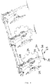
- eine Seitenansicht des Bodenbearbeitungsgeräts aus den vorhergehenden Figuren, die die Anordnung der hinteren Fahrwerksachse hinter der hintersten Grubberzinkenreihe und die Anordnung der Lockerungswerkzeuge hinter besagter Fahrwerksachse zeigt,
- Fig. 4
- eine perspektivische Rückansicht der Lockerungswerkzeuge des Bodenbearbeitungsgeräts aus den vorhergehenden Figuren, wobei die Lockerungszinken und die zugeordneten Schrägscheiben in Arbeitsposition gezeigt sind,
- Fig. 5
- eine perspektivische Rückansicht der Lockerungswerkzeuge, ähnlich
Fig. 4 , wobei die Lockerungszinken vergleichsweise einmal in Arbeitsposition und einmal in Nicht-Arbeitsposition gezeigt sind, und - Fig. 6
- eine Seitenansicht der Lockerungswerkzeuge aus den vorhergehenden Figuren, die die verschiebliche Verstellbarkeit der Lockerungszinken und deren Positionierung in Arbeitsposition und Nicht-Arbeitsposition zeigt.
- Fig. 1
- 2 shows a perspective rear view of a tillage implement in the form of a drawn cultivator according to an advantageous embodiment of the invention, the undercarriage integrated in the field of the cultivator tines being shown in a lowered tillage position,
- Fig. 2
- a rear perspective view of the tillage implement
Fig. 1 , without trailer, whereby the loosening tools arranged in the direction of travel behind the chassis and in the configuration with trailer in front of the trailer can be seen to loosen up the lanes compacted by the chassis, - Fig. 3
- 2 shows a side view of the tillage implement from the previous figures, which shows the arrangement of the rear chassis axle behind the rearmost row of cultivator tines and the arrangement of the loosening tools behind said chassis axle,
- Fig. 4
- 3 shows a perspective rear view of the loosening tools of the tillage implement from the previous figures, the loosening tines and the associated swash plates being shown in the working position,
- Fig. 5
- a rear perspective view of the loosening tools, similar
Fig. 4 , the loosening tines being shown comparatively once in the working position and once in the non-working position, and - Fig. 6
- a side view of the loosening tools from the previous figures, showing the displaceable adjustability of the loosening tines and their positioning in the working position and non-working position.
Wie die Figuren zeigen, kann das gezogene Anbaugerät zur Bodenbearbeitung insbesondere als Grubber ausgebildet sein. Anstelle eines solchen gezogenen Anbaugrubbers 1 mit Grubberzinken könnte das Anbaugerät aber auch andere Bodenbearbeitungswerkzeuge wie Scharscheiben aufweisen und als Scheibenegge, oder auch als Kombinationsgerät mit verschieden ausgebildeten Bodenbearbeitungswerkzeugen ausgebildet sein. Wenn nachfolgend von Grubberzinken oder einem Mittelzinken gesprochen wird kann gleichermaßen bei anderer Ausbildung des gezogenen Anbaugeräts ein entsprechend anderes Bodenbearbeitungswerkzeug, wie eine Scharscheibe oder dergleichen, gemeint sein.As the figures show, the towed implement for tillage can be designed in particular as a cultivator. Instead of such a
Wie
Den Grubberzinken 4 hinterherlaufend können eine oder mehrere Nachbearbeitungseinheiten 5 vorgesehen sein, beispielsweise in Form von Zustreichern und einer Nachläuferwalze, beispielsweise in Form einer Federscheibenwalze.Running behind the
Wie
Wie
Wie die
An einem vorderen Endabschnitt der Deichsel 8 kann ein Ankoppelgelenk 9 vorgesehen sein, welches ein Verschwenken der Deichsel 8 gegenüber dem Schlepper zumindest um eine aufrechte Achse, vorteilhafterweise aber auch mehrachsig erlaubt. Beispielsweise kann der in den Figuren gezeigte Querlenker 10, der an den Unterlenkern des Schleppers eingehängt werden kann, um ein Ankoppelgelenk 9 gegenüber der Deichsel 8 verschwenkt werden. Alternativ zu einem solchen Querlenker 10 können aber auch andere Anbaumittel und -gelenke Verwendung finden, beispielsweise ein Kugelgelenk bzw. ein Kugelkopf oder eine Zugöse oder ähnliche gelenkige Anbau- bzw. Ankoppelmittel.At a front end section of the
An einem vorderen Endabschnitt der Deichsel 8 kann ein Ankoppelgelenk 9 vorgesehen sein, welches ein Verschwenken der Deichsel 8 gegenüber dem Schlepper zumindest um eine aufrechte Achse, vorteilhafterweise aber auch mehrachsig erlaubt. Beispielsweise kann der in den Figuren gezeigte Querlenker 10, der an den Unterlenkern des Schleppers eingehängt werden kann, um ein Ankoppelgelenk 9 gegenüber der Deichsel 8 verschwenkt werden. Alternativ zu einem solchen Querlenker 10 können aber auch andere Anbaumittel und -gelenke Verwendung finden, beispielsweise ein Kugelgelenk bzw. ein Kugelkopf oder eine Zugöse oder ähnliche gelenkige Anbau- bzw. Ankoppelmittel.At a front end section of the
Vorteilhafterweise ist die genannte Deichsel 8 an dem Maschinenrahmen 2 um eine liegende Querachse schwenkbar angelenkt, so dass die Deichsel 8 gegenüber dem Maschinenrahmen 2 auf- und niederwippen kann. Insbesondere kann die Deichsel 8 an einem vordersten der genannten Querträger 3 des Maschinenrahmens 2 angelenkt sein, wobei sich die liegende Deichselschwenkachse insbesondere parallel an dem vordersten Querträger 3 erstrecken kann.Advantageously, said
Die Deichsel 8 ist dabei über eine Deichselstützstrebe 12 an einem Kopf 13 des Maschinenrahmens 2 abgestützt, wobei die genannte Deichselstützstrebe 12 einerseits an der Deichsel 8 angelenkt und andererseits an besagtem Kopf 13 des Maschinenrahmens 2 angelenkt ist und an sich die Schwenkbewegung der Deichsel 8 um die zuvor genannte Deichselschwenkachse 11 blockiert bzw. begrenzt.The
Vorteilhafterweise kann die genannte Deichselstützstrebe 12 längenveränderbar ausgebildet sein, beispielsweise teleskopierbar sein und zwei oder auch mehr ineinander schiebbare Strebenteile umfassen. Alternativ oder zusätzlich kann auch ein am Kopf 13 oder der Deichsel 8 verschiebbarer Anlenkpunkt für die Deichselstützstrebe 12 vorgesehen sein, beispielsweise in Form einer Langlochführung oder einer anderen Schiebeführung, um die effektive Länge der Deichselstützstrebe 12 justieren zu können.Advantageously, the drawbar support strut 12 can be designed to be variable in length, for example be telescopic and comprise two or more strut parts which can be pushed into one another. Alternatively or additionally, a pivot point on the
Wie die
Die hintere Fahrwerksachse 7b kann ebenfalls im Bereich des hinteren Randabschnitts des Grubberzinkenfelds sein und insbesondere etwa auf Höhe der hintersten Grubberzinken 4 oder gegebenenfalls auch leicht dahinter angeordnet sein. Die Räder 23 der hinteren Fahrwerksachse 7b können eine geringere Spurbreite als die vordere Fahrwerksachse 7a definieren, wobei die Spurbreite bzw. der Abstand der beiden Räder 23 der hinteren Fahrwerksachse 7b beispielsweise kleiner sein kann als die Breite des Grubberzinkenfelds, insbesondere etwa im Bereich von 50 % bis 90 % der maximalen Breite des Grubberzinkenfelds.The rear chassis axis 7b can also be in the area of the rear edge section of the cultivator tine field and in particular be arranged approximately at the level of the
Wie
Das Fahrwerk 7 ist vorteilhafterweise höhenverstellbar ausgebildet, so dass die Räder 23 des Fahrwerks 7 relativ zum Maschinenrahmen 2 abgesenkt und abgehoben werden können. Beispielsweise können die Achsen der Räder 23 an Achsträgerschwingen aufgehängt sein, die schwenkbar am Maschinenrahmen 2 gelagert sein können, so dass die Räder durch Verschwenken der Achsschwingen hoch- und tiefverstellt werden können.The
Grundsätzlich wäre es aber auch möglich, ein nicht-höhenverstellbares Fahrwerk 7 zu verwenden, wobei dann das Fahrwerk 7 die in den Zeichnungen dargestellte Bodenbearbeitungsstellung einnimmt.In principle, however, it would also be possible to use a non-height-
Ist das Fahrwerk 7 höhenverstellbar, kann einerseits die in den Zeichnungen dargestellte Bodenbearbeitungsstellung eingestellt werden, in der die Grubberzinken 4 ein Stück weit unter der Bodenaufstandsfläche des Fahrwerks 7 laufen, so dass die Höhendifferenz zwischen der Bodenaufstandsfläche des Fahrwerks 7 und den Grubberzinken 4 bzw. deren unteren Endabschnitt die Bearbeitungstiefe zumindest näherungsweise darstellt. Andererseits kann das Fahrwerk bei Höhenverstellbarkeit gleichzeitig auch als Transportfahrwerk dienen, wobei das Fahrwerk 7 hierzu in eine Transportstellung - im Vergleich zur in den Zeichnungen gezeigten Bodenbearbeitungsstellung - weiter gegenüber dem Maschinenrahmen 2 abgesenkt wird, so dass die Grubberzinken 4 mit ihren unteren Endabschnitten ausreichend weit oberhalb der Bodenaufstandsfläche des Fahrwerks 7 zu liegen kommen, um beim Straßentransport nicht am Boden zu kratzen.If the
Ferner die Höhenverstellbarkeit des Fahrwerks 7 derart ausgebildet sein, dass das Fahrwerk 7 in eine Inaktiv-Stellung verbringbar ist, insbesondere, wenn das Gerät auf dem Nachläufer bzw. der Nachläufereinheit 5 abgestützt werden soll. Hierzu wird dann das Fahrwerk 7 soweit nach oben über die in den Zeichnungen gezeigte Bodenbearbeitungsstellung weiter ausgehoben, so dass das Gerät nicht mehr auf dem Fahrwerk 7, sondern auf dem Nachläufer 5 abgestützt ist.Furthermore, the height adjustability of the
Wie
Wie ebenfalls
Die genannten Lockerungswerkzeuge 24 sind dabei von den Bodenbearbeitungswerkzeugen, die die bestimmungsgemäße Bodenbearbeitung des Anbaugeräts 1 gemäß dessen Verwendungszweck ausführen, verschieden ausgebildet. Insbesondere können die Lockerungswerkzeuge 24 den Boden in geringerem Maße bearbeiten und/oder weniger Bearbeitungsenergie in den Boden einbringen als die vor der Fahrwerksachse 7b angebrachten Bodenbearbeitungswerkzeuge. Insbesondere können die Lockerungswerkzeuge 24 eine geringere Arbeitstiefe und/oder eine geringere, aktive Eingriffsfläche, die bestimmungsgemäß in den Boden eingreift, aufweisen, als die der Fahrwerksachse 7b vorauslaufenden Bodenbearbeitungswerkzeuge. Im Vergleich zu den Grubberzinken 4 können die besagten Lockerungswerkzeuge 24 eine geringere Arbeitstiefe und kürzere und/oder kleinere Eingriffsflügel aufweisen.The
Die besagten Lockerungswerkzeuge 24 können insbesondere Lockerungszinken 25 aufweisen, die einen vorzugsweise schräg nach unten weisenden Zinkenkorpus umfassen, dessen unteres Ende in den Boden eingreift, um den Boden aufzulockern. Wie
Wie
Wie
Die Lockerungszinken 25 können einen im Wesentlichen geraden Führungsabschnitt aufweisen, welcher in der genannten Linearführung 27 geführt ist. Unabhängig hiervon können die Lockerungszinken 25 zu ihrem unteren Endabschnitt hin eine Abkröpfung 29 aufweisen, durch die sich der Zinkenkorpus zu seinem unteren Endabschnitt hin zunehmend steiler auf den Boden zu erstreckt, vgl.
Die Lockerungszinken 25 können in der Linearführung 27 in verschiedenen Stellungen fixiert, bzw. blockiert werden, um verschiedene Höheneinstellungen vornehmen zu können. Beispielsweise kann in dem Zinkenkorpus ein Lochbild oder Ausnehmungsbild vorgesehen sein, in das ein Riegel, beispielsweise in Form eines Steckbolzens, eingreifen und den Zinken blockieren kann.The loosening
Wie die
Die Lockerungswerkzeuge 24 können alternativ oder zusätzlich zu den besagten Lockerungszinken 25 auch noch Bodeneingriffsscheiben 29 aufweisen, die insbesondere als Schrägscheiben ausgebildet sein können, die um eine Drehachse drehbar gelagert sind, welche Drehachse sich gegenüber eine horizontalen Ebene spitzwinklig geneigt und/oder gegenüber einer vertikalen Querebene, die sich senkrecht zur Fahrtrichtung erstreckt, spitzwinklig geneigt sein können. Insbesondere können die besagten Scheiben 29 paarweise angeordnet und so schräg gestellt sein, dass sie einen zwischen sich V-förmig aufgespreizten Raum begrenzen, dessen Hauptachse sich entgegen der Fahrtrichtung schräg nach hinten oben erstrecken kann, d.h. die Scheiben eines Scheibenpaars laufen nach hinten/oben auseinander, wie dies die
Die genannten Scheiben 29 bzw. ein entsprechendes Scheibenpaar kann jeweils einem Lockerungszinken 25 zugeordnet sein, so dass ein Scheibenpaar jeweils einem Lockerungszinken 25 vorausläuft. Die Scheiben 29, die einem Lockerungszinken 25 zugeordnet sind, können dabei ein stück weit voneinander beabstandet sein, so dass der nachlaufende Lockerungszinken 25 in einem Spurbereich zwischen den zugeordneten Scheiben 29 läuft.Said
Wie
Die Lockerungszinken 25 können also vorteilhafterweise relativ zu den zugeordneten Scheiben 29 höhenverstellt werden.The loosening
Claims (15)
Applications Claiming Priority (1)
| Application Number | Priority Date | Filing Date | Title |
|---|---|---|---|
| DE202018105099.0U DE202018105099U1 (en) | 2018-09-06 | 2018-09-06 | Harrow |
Publications (2)
| Publication Number | Publication Date |
|---|---|
| EP3620037A1 true EP3620037A1 (en) | 2020-03-11 |
| EP3620037B1 EP3620037B1 (en) | 2023-08-30 |
Family
ID=67437950
Family Applications (1)
| Application Number | Title | Priority Date | Filing Date |
|---|---|---|---|
| EP19186939.5A Active EP3620037B1 (en) | 2018-09-06 | 2019-07-18 | Soil working device |
Country Status (2)
| Country | Link |
|---|---|
| EP (1) | EP3620037B1 (en) |
| DE (1) | DE202018105099U1 (en) |
Families Citing this family (1)
| Publication number | Priority date | Publication date | Assignee | Title |
|---|---|---|---|---|
| DE102021117388A1 (en) | 2021-07-06 | 2023-01-12 | Horsch Maschinen Gmbh | tillage device |
Citations (7)
| Publication number | Priority date | Publication date | Assignee | Title |
|---|---|---|---|---|
| DE2735902A1 (en) * | 1977-06-08 | 1978-12-14 | Werner Ullrich | Track perforator with sprung share - having staggered pairs of side plates which diverge towards outer ends |
| DE2945896A1 (en) * | 1979-11-14 | 1981-05-21 | Amazonen-Werke H. Dreyer Gmbh & Co Kg, 4507 Hasbergen | DEVICE COMBINATION FOR SEEDBED PREPARATION |
| CA2223782A1 (en) * | 1997-12-05 | 1999-06-05 | Darin Hubscher | Cultivator |
| EP2279652A1 (en) | 2009-07-27 | 2011-02-02 | Paul Treffler | Grubber |
| DE102010000527A1 (en) * | 2010-02-24 | 2011-08-25 | Amazonen-Werke H. Dreyer GmbH & Co. KG, 49205 | Sowing machine for delivering seeds and fertilizers, has frame, storage containers, sowing shares and roller-shaped depth guiding elements that are engaged to driving direction in inclined manner |
| WO2017013175A1 (en) * | 2015-07-21 | 2017-01-26 | Amazonen-Werke H. Dreyer Gmbh & Co. Kg | Sowing machine |
| DE102016118093A1 (en) * | 2016-09-26 | 2018-03-29 | Amazonen-Werke H. Dreyer Gmbh & Co. Kg | Seeder for spreading seed and / or fertilizer |
Family Cites Families (2)
| Publication number | Priority date | Publication date | Assignee | Title |
|---|---|---|---|---|
| US3757871A (en) * | 1972-01-26 | 1973-09-11 | Deere & Co | Minimum tillage agricultural implement |
| US4567689A (en) * | 1983-12-30 | 1986-02-04 | Lemons Daniel P | Vineyard cultivator |
-
2018
- 2018-09-06 DE DE202018105099.0U patent/DE202018105099U1/en active Active
-
2019
- 2019-07-18 EP EP19186939.5A patent/EP3620037B1/en active Active
Patent Citations (7)
| Publication number | Priority date | Publication date | Assignee | Title |
|---|---|---|---|---|
| DE2735902A1 (en) * | 1977-06-08 | 1978-12-14 | Werner Ullrich | Track perforator with sprung share - having staggered pairs of side plates which diverge towards outer ends |
| DE2945896A1 (en) * | 1979-11-14 | 1981-05-21 | Amazonen-Werke H. Dreyer Gmbh & Co Kg, 4507 Hasbergen | DEVICE COMBINATION FOR SEEDBED PREPARATION |
| CA2223782A1 (en) * | 1997-12-05 | 1999-06-05 | Darin Hubscher | Cultivator |
| EP2279652A1 (en) | 2009-07-27 | 2011-02-02 | Paul Treffler | Grubber |
| DE102010000527A1 (en) * | 2010-02-24 | 2011-08-25 | Amazonen-Werke H. Dreyer GmbH & Co. KG, 49205 | Sowing machine for delivering seeds and fertilizers, has frame, storage containers, sowing shares and roller-shaped depth guiding elements that are engaged to driving direction in inclined manner |
| WO2017013175A1 (en) * | 2015-07-21 | 2017-01-26 | Amazonen-Werke H. Dreyer Gmbh & Co. Kg | Sowing machine |
| DE102016118093A1 (en) * | 2016-09-26 | 2018-03-29 | Amazonen-Werke H. Dreyer Gmbh & Co. Kg | Seeder for spreading seed and / or fertilizer |
Also Published As
| Publication number | Publication date |
|---|---|
| DE202018105099U1 (en) | 2019-12-09 |
| EP3620037B1 (en) | 2023-08-30 |
Similar Documents
| Publication | Publication Date | Title |
|---|---|---|
| EP2605632B1 (en) | Towed agricultural machine with packer unit | |
| DE102014107515A1 (en) | Plow with several mounted on a plow beam plow bodies | |
| DE102017116633A1 (en) | Agricultural tillage machine | |
| EP1731009A1 (en) | Reversible plough with pressure control unit | |
| EP3620037B1 (en) | Soil working device | |
| EP3620038B1 (en) | Towed cultivator | |
| DE202007016639U1 (en) | Riding land maintenance equipment | |
| EP0211967A1 (en) | Combined implement for soil cultivation in agriculture | |
| EP0350513B1 (en) | Soil working equipment | |
| DE3431796C2 (en) | ||
| DE102020133571A1 (en) | tillage implement | |
| DE2521023A1 (en) | MULTIPLE SEMI-DETACHED PLOW | |
| EP2371194B1 (en) | Device for spreading seeds and/or fertilisers | |
| DE3412962A1 (en) | CARRIER FOR AN AGRICULTURAL DEVICE | |
| DE102006019032B4 (en) | Foldable agricultural order combination | |
| DE3337193C2 (en) | ||
| EP2091315B1 (en) | Soil treatment device having a large working width | |
| EP2113159A1 (en) | Grubber | |
| DE2616241C2 (en) | Towed reversible plow for tractors driving next to the furrow | |
| DE2607082A1 (en) | PLOW | |
| EP4298880A1 (en) | Agricultural machine, preferably tractor, with a pivoting arm | |
| EP4124217A1 (en) | Agricultural soil working machine and method for parking it in a parking position | |
| DE3448328C2 (en) | Rotary ground cultivation machine | |
| DE941698C (en) | Agricultural tools, especially for tillage | |
| DE202020107056U1 (en) | Plow with several plow bodies attached to a plow beam aligned at right angles to the working direction of the plow |
Legal Events
| Date | Code | Title | Description |
|---|---|---|---|
| PUAI | Public reference made under article 153(3) epc to a published international application that has entered the european phase |
Free format text: ORIGINAL CODE: 0009012 |
|
| STAA | Information on the status of an ep patent application or granted ep patent |
Free format text: STATUS: THE APPLICATION HAS BEEN PUBLISHED |
|
| AK | Designated contracting states |
Kind code of ref document: A1 Designated state(s): AL AT BE BG CH CY CZ DE DK EE ES FI FR GB GR HR HU IE IS IT LI LT LU LV MC MK MT NL NO PL PT RO RS SE SI SK SM TR |
|
| AX | Request for extension of the european patent |
Extension state: BA ME |
|
| STAA | Information on the status of an ep patent application or granted ep patent |
Free format text: STATUS: REQUEST FOR EXAMINATION WAS MADE |
|
| 17P | Request for examination filed |
Effective date: 20200911 |
|
| RBV | Designated contracting states (corrected) |
Designated state(s): AL AT BE BG CH CY CZ DE DK EE ES FI FR GB GR HR HU IE IS IT LI LT LU LV MC MK MT NL NO PL PT RO RS SE SI SK SM TR |
|
| STAA | Information on the status of an ep patent application or granted ep patent |
Free format text: STATUS: EXAMINATION IS IN PROGRESS |
|
| 17Q | First examination report despatched |
Effective date: 20211220 |
|
| GRAP | Despatch of communication of intention to grant a patent |
Free format text: ORIGINAL CODE: EPIDOSNIGR1 |
|
| STAA | Information on the status of an ep patent application or granted ep patent |
Free format text: STATUS: GRANT OF PATENT IS INTENDED |
|
| INTG | Intention to grant announced |
Effective date: 20230213 |
|
| GRAS | Grant fee paid |
Free format text: ORIGINAL CODE: EPIDOSNIGR3 |
|
| P01 | Opt-out of the competence of the unified patent court (upc) registered |
Effective date: 20230613 |
|
| GRAA | (expected) grant |
Free format text: ORIGINAL CODE: 0009210 |
|
| STAA | Information on the status of an ep patent application or granted ep patent |
Free format text: STATUS: THE PATENT HAS BEEN GRANTED |
|
| AK | Designated contracting states |
Kind code of ref document: B1 Designated state(s): AL AT BE BG CH CY CZ DE DK EE ES FI FR GB GR HR HU IE IS IT LI LT LU LV MC MK MT NL NO PL PT RO RS SE SI SK SM TR |
|
| REG | Reference to a national code |
Ref country code: GB Ref legal event code: FG4D Free format text: NOT ENGLISH |
|
| REG | Reference to a national code |
Ref country code: CH Ref legal event code: EP |
|
| REG | Reference to a national code |
Ref country code: DE Ref legal event code: R096 Ref document number: 502019009119 Country of ref document: DE |
|
| REG | Reference to a national code |
Ref country code: IE Ref legal event code: FG4D Free format text: LANGUAGE OF EP DOCUMENT: GERMAN |
|
| REG | Reference to a national code |
Ref country code: LT Ref legal event code: MG9D Ref country code: SE Ref legal event code: TRGR |
|
| REG | Reference to a national code |
Ref country code: NL Ref legal event code: MP Effective date: 20230830 |
|
| PG25 | Lapsed in a contracting state [announced via postgrant information from national office to epo] |
Ref country code: GR Free format text: LAPSE BECAUSE OF FAILURE TO SUBMIT A TRANSLATION OF THE DESCRIPTION OR TO PAY THE FEE WITHIN THE PRESCRIBED TIME-LIMIT Effective date: 20231201 |
|
| PG25 | Lapsed in a contracting state [announced via postgrant information from national office to epo] |
Ref country code: IS Free format text: LAPSE BECAUSE OF FAILURE TO SUBMIT A TRANSLATION OF THE DESCRIPTION OR TO PAY THE FEE WITHIN THE PRESCRIBED TIME-LIMIT Effective date: 20231230 |
|
| PG25 | Lapsed in a contracting state [announced via postgrant information from national office to epo] |
Ref country code: RS Free format text: LAPSE BECAUSE OF FAILURE TO SUBMIT A TRANSLATION OF THE DESCRIPTION OR TO PAY THE FEE WITHIN THE PRESCRIBED TIME-LIMIT Effective date: 20230830 Ref country code: NO Free format text: LAPSE BECAUSE OF FAILURE TO SUBMIT A TRANSLATION OF THE DESCRIPTION OR TO PAY THE FEE WITHIN THE PRESCRIBED TIME-LIMIT Effective date: 20231130 Ref country code: LV Free format text: LAPSE BECAUSE OF FAILURE TO SUBMIT A TRANSLATION OF THE DESCRIPTION OR TO PAY THE FEE WITHIN THE PRESCRIBED TIME-LIMIT Effective date: 20230830 Ref country code: LT Free format text: LAPSE BECAUSE OF FAILURE TO SUBMIT A TRANSLATION OF THE DESCRIPTION OR TO PAY THE FEE WITHIN THE PRESCRIBED TIME-LIMIT Effective date: 20230830 Ref country code: IS Free format text: LAPSE BECAUSE OF FAILURE TO SUBMIT A TRANSLATION OF THE DESCRIPTION OR TO PAY THE FEE WITHIN THE PRESCRIBED TIME-LIMIT Effective date: 20231230 Ref country code: HR Free format text: LAPSE BECAUSE OF FAILURE TO SUBMIT A TRANSLATION OF THE DESCRIPTION OR TO PAY THE FEE WITHIN THE PRESCRIBED TIME-LIMIT Effective date: 20230830 Ref country code: GR Free format text: LAPSE BECAUSE OF FAILURE TO SUBMIT A TRANSLATION OF THE DESCRIPTION OR TO PAY THE FEE WITHIN THE PRESCRIBED TIME-LIMIT Effective date: 20231201 Ref country code: FI Free format text: LAPSE BECAUSE OF FAILURE TO SUBMIT A TRANSLATION OF THE DESCRIPTION OR TO PAY THE FEE WITHIN THE PRESCRIBED TIME-LIMIT Effective date: 20230830 |
|
| PG25 | Lapsed in a contracting state [announced via postgrant information from national office to epo] |
Ref country code: PL Free format text: LAPSE BECAUSE OF FAILURE TO SUBMIT A TRANSLATION OF THE DESCRIPTION OR TO PAY THE FEE WITHIN THE PRESCRIBED TIME-LIMIT Effective date: 20230830 Ref country code: NL Free format text: LAPSE BECAUSE OF FAILURE TO SUBMIT A TRANSLATION OF THE DESCRIPTION OR TO PAY THE FEE WITHIN THE PRESCRIBED TIME-LIMIT Effective date: 20230830 |
|
| PG25 | Lapsed in a contracting state [announced via postgrant information from national office to epo] |
Ref country code: ES Free format text: LAPSE BECAUSE OF FAILURE TO SUBMIT A TRANSLATION OF THE DESCRIPTION OR TO PAY THE FEE WITHIN THE PRESCRIBED TIME-LIMIT Effective date: 20230830 |
|
| PG25 | Lapsed in a contracting state [announced via postgrant information from national office to epo] |
Ref country code: SM Free format text: LAPSE BECAUSE OF FAILURE TO SUBMIT A TRANSLATION OF THE DESCRIPTION OR TO PAY THE FEE WITHIN THE PRESCRIBED TIME-LIMIT Effective date: 20230830 Ref country code: RO Free format text: LAPSE BECAUSE OF FAILURE TO SUBMIT A TRANSLATION OF THE DESCRIPTION OR TO PAY THE FEE WITHIN THE PRESCRIBED TIME-LIMIT Effective date: 20230830 Ref country code: ES Free format text: LAPSE BECAUSE OF FAILURE TO SUBMIT A TRANSLATION OF THE DESCRIPTION OR TO PAY THE FEE WITHIN THE PRESCRIBED TIME-LIMIT Effective date: 20230830 Ref country code: EE Free format text: LAPSE BECAUSE OF FAILURE TO SUBMIT A TRANSLATION OF THE DESCRIPTION OR TO PAY THE FEE WITHIN THE PRESCRIBED TIME-LIMIT Effective date: 20230830 Ref country code: DK Free format text: LAPSE BECAUSE OF FAILURE TO SUBMIT A TRANSLATION OF THE DESCRIPTION OR TO PAY THE FEE WITHIN THE PRESCRIBED TIME-LIMIT Effective date: 20230830 Ref country code: SK Free format text: LAPSE BECAUSE OF FAILURE TO SUBMIT A TRANSLATION OF THE DESCRIPTION OR TO PAY THE FEE WITHIN THE PRESCRIBED TIME-LIMIT Effective date: 20230830 Ref country code: PT Free format text: LAPSE BECAUSE OF FAILURE TO SUBMIT A TRANSLATION OF THE DESCRIPTION OR TO PAY THE FEE WITHIN THE PRESCRIBED TIME-LIMIT Effective date: 20240102 |