EP3618238A1 - Motor - Google Patents
Motor Download PDFInfo
- Publication number
- EP3618238A1 EP3618238A1 EP18790386.9A EP18790386A EP3618238A1 EP 3618238 A1 EP3618238 A1 EP 3618238A1 EP 18790386 A EP18790386 A EP 18790386A EP 3618238 A1 EP3618238 A1 EP 3618238A1
- Authority
- EP
- European Patent Office
- Prior art keywords
- terminal
- motor
- extension
- connecting end
- stator
- Prior art date
- Legal status (The legal status is an assumption and is not a legal conclusion. Google has not performed a legal analysis and makes no representation as to the accuracy of the status listed.)
- Pending
Links
Images




Classifications
-
- H—ELECTRICITY
- H02—GENERATION; CONVERSION OR DISTRIBUTION OF ELECTRIC POWER
- H02K—DYNAMO-ELECTRIC MACHINES
- H02K5/00—Casings; Enclosures; Supports
- H02K5/04—Casings or enclosures characterised by the shape, form or construction thereof
- H02K5/22—Auxiliary parts of casings not covered by groups H02K5/06-H02K5/20, e.g. shaped to form connection boxes or terminal boxes
- H02K5/225—Terminal boxes or connection arrangements
-
- H—ELECTRICITY
- H02—GENERATION; CONVERSION OR DISTRIBUTION OF ELECTRIC POWER
- H02K—DYNAMO-ELECTRIC MACHINES
- H02K3/00—Details of windings
- H02K3/32—Windings characterised by the shape, form or construction of the insulation
- H02K3/38—Windings characterised by the shape, form or construction of the insulation around winding heads, equalising connectors, or connections thereto
-
- B—PERFORMING OPERATIONS; TRANSPORTING
- B62—LAND VEHICLES FOR TRAVELLING OTHERWISE THAN ON RAILS
- B62D—MOTOR VEHICLES; TRAILERS
- B62D5/00—Power-assisted or power-driven steering
- B62D5/04—Power-assisted or power-driven steering electrical, e.g. using an electric servo-motor connected to, or forming part of, the steering gear
-
- H—ELECTRICITY
- H02—GENERATION; CONVERSION OR DISTRIBUTION OF ELECTRIC POWER
- H02K—DYNAMO-ELECTRIC MACHINES
- H02K1/00—Details of the magnetic circuit
- H02K1/06—Details of the magnetic circuit characterised by the shape, form or construction
- H02K1/12—Stationary parts of the magnetic circuit
- H02K1/16—Stator cores with slots for windings
- H02K1/165—Shape, form or location of the slots
-
- H—ELECTRICITY
- H02—GENERATION; CONVERSION OR DISTRIBUTION OF ELECTRIC POWER
- H02K—DYNAMO-ELECTRIC MACHINES
- H02K11/00—Structural association of dynamo-electric machines with electric components or with devices for shielding, monitoring or protection
- H02K11/20—Structural association of dynamo-electric machines with electric components or with devices for shielding, monitoring or protection for measuring, monitoring, testing, protecting or switching
-
- H—ELECTRICITY
- H02—GENERATION; CONVERSION OR DISTRIBUTION OF ELECTRIC POWER
- H02K—DYNAMO-ELECTRIC MACHINES
- H02K11/00—Structural association of dynamo-electric machines with electric components or with devices for shielding, monitoring or protection
- H02K11/20—Structural association of dynamo-electric machines with electric components or with devices for shielding, monitoring or protection for measuring, monitoring, testing, protecting or switching
- H02K11/21—Devices for sensing speed or position, or actuated thereby
- H02K11/215—Magnetic effect devices, e.g. Hall-effect or magneto-resistive elements
-
- H—ELECTRICITY
- H02—GENERATION; CONVERSION OR DISTRIBUTION OF ELECTRIC POWER
- H02K—DYNAMO-ELECTRIC MACHINES
- H02K21/00—Synchronous motors having permanent magnets; Synchronous generators having permanent magnets
- H02K21/12—Synchronous motors having permanent magnets; Synchronous generators having permanent magnets with stationary armatures and rotating magnets
- H02K21/14—Synchronous motors having permanent magnets; Synchronous generators having permanent magnets with stationary armatures and rotating magnets with magnets rotating within the armatures
- H02K21/16—Synchronous motors having permanent magnets; Synchronous generators having permanent magnets with stationary armatures and rotating magnets with magnets rotating within the armatures having annular armature cores with salient poles
-
- H—ELECTRICITY
- H02—GENERATION; CONVERSION OR DISTRIBUTION OF ELECTRIC POWER
- H02K—DYNAMO-ELECTRIC MACHINES
- H02K29/00—Motors or generators having non-mechanical commutating devices, e.g. discharge tubes or semiconductor devices
- H02K29/06—Motors or generators having non-mechanical commutating devices, e.g. discharge tubes or semiconductor devices with position sensing devices
- H02K29/08—Motors or generators having non-mechanical commutating devices, e.g. discharge tubes or semiconductor devices with position sensing devices using magnetic effect devices, e.g. Hall-plates, magneto-resistors
-
- H—ELECTRICITY
- H02—GENERATION; CONVERSION OR DISTRIBUTION OF ELECTRIC POWER
- H02K—DYNAMO-ELECTRIC MACHINES
- H02K3/00—Details of windings
- H02K3/04—Windings characterised by the conductor shape, form or construction, e.g. with bar conductors
- H02K3/12—Windings characterised by the conductor shape, form or construction, e.g. with bar conductors arranged in slots
-
- H—ELECTRICITY
- H02—GENERATION; CONVERSION OR DISTRIBUTION OF ELECTRIC POWER
- H02K—DYNAMO-ELECTRIC MACHINES
- H02K3/00—Details of windings
- H02K3/46—Fastening of windings on the stator or rotor structure
- H02K3/48—Fastening of windings on the stator or rotor structure in slots
-
- H—ELECTRICITY
- H02—GENERATION; CONVERSION OR DISTRIBUTION OF ELECTRIC POWER
- H02K—DYNAMO-ELECTRIC MACHINES
- H02K3/00—Details of windings
- H02K3/46—Fastening of windings on the stator or rotor structure
- H02K3/52—Fastening salient pole windings or connections thereto
- H02K3/521—Fastening salient pole windings or connections thereto applicable to stators only
- H02K3/522—Fastening salient pole windings or connections thereto applicable to stators only for generally annular cores with salient poles
-
- B—PERFORMING OPERATIONS; TRANSPORTING
- B62—LAND VEHICLES FOR TRAVELLING OTHERWISE THAN ON RAILS
- B62D—MOTOR VEHICLES; TRAILERS
- B62D5/00—Power-assisted or power-driven steering
- B62D5/04—Power-assisted or power-driven steering electrical, e.g. using an electric servo-motor connected to, or forming part of, the steering gear
- B62D5/0403—Power-assisted or power-driven steering electrical, e.g. using an electric servo-motor connected to, or forming part of, the steering gear characterised by constructional features, e.g. common housing for motor and gear box
- B62D5/0406—Power-assisted or power-driven steering electrical, e.g. using an electric servo-motor connected to, or forming part of, the steering gear characterised by constructional features, e.g. common housing for motor and gear box including housing for electronic control unit
-
- H—ELECTRICITY
- H02—GENERATION; CONVERSION OR DISTRIBUTION OF ELECTRIC POWER
- H02K—DYNAMO-ELECTRIC MACHINES
- H02K2203/00—Specific aspects not provided for in the other groups of this subclass relating to the windings
- H02K2203/09—Machines characterised by wiring elements other than wires, e.g. bus rings, for connecting the winding terminations
-
- H—ELECTRICITY
- H02—GENERATION; CONVERSION OR DISTRIBUTION OF ELECTRIC POWER
- H02K—DYNAMO-ELECTRIC MACHINES
- H02K2203/00—Specific aspects not provided for in the other groups of this subclass relating to the windings
- H02K2203/15—Machines characterised by cable windings, e.g. high-voltage cables, ribbon cables
Definitions
- the present invention relates to a motor.
- An electric power steering system is a system which secures turning stability of a vehicle and rapid restoring force so that a driver can stably drive.
- the EPS drives a motor to control operation of a steering shaft of the vehicle through an electronic control unit (ECU) according to travel conditions detected by a vehicle speed sensor, a torque angle sensor, and the like.
- ECU electronice control unit
- the motor includes a rotor and a stator.
- a coil is wound around the stator.
- a connecting end portion of the coil wound around the stator may be connected to a busbar.
- the busbar may include a terminal connected to the connecting end portion of the coil.
- the terminal of the busbar may be connected to the connecting end portion of the coil wound around the stator and connected to a wire assembly.
- the wire assembly is connected to an external power source.
- a terminal of the wire assembly is connected to the terminal of the busbar by fusing.
- a fusing process has problems of being a difficult operation, having a high failure rate, and increasing cost.
- the fusing process is needed for each terminal of three phases, there is a problem in that the number of manufacturing processes is increased.
- the present invention is directed to providing a motor of which a terminal of a wire assembly is connectable to a terminal of a busbar without performing a fusing process.
- a motor including a shaft, a rotor including a hole in which the shaft is disposed, a stator disposed outside the rotor, a busbar disposed above the stator, and a wire assembly connected to the busbar, wherein the wire assembly includes a grommet, a cable of which a part is disposed inside the grommet, and a first terminal connected to the cable.
- the first terminal includes a connecting end portion
- the grommet includes a body having the cable therein and an extension extending from the body and having the first terminal therein
- the extension includes an insert hole formed to pass through from a lower surface of the extension to an upper surface of the extension
- the connecting end portion is disposed inside the insert hole.
- the busbar may include a second terminal, and the first terminal and the second terminal are insertion-coupled.
- the second terminal may include a connector connected to a coil wound around the stator and a clip protruding upward from one side of the connector and coupled to the connecting end portion of the first terminal.
- the clip may include a slot which is concavely formed from an upper end of the clip toward a lower side thereof and to which the connecting end portion of the first terminal is insertion-coupled.
- the slot may include a hooking step protruding from a sidewall of the slot and configured to restrict movement of the connecting end portion of the first terminal.
- the second terminal may include a base having a ring shape and a plurality of terminals connected to the base, and any one of the plurality of terminals may include the clip.
- the clip may be disposed inside the insert hole.
- the connecting end portion of the first terminal may have a shape bent such as a " " shape.
- the motor may further include a a sensing magnet coupled to the shaft, wherein a front surface of the extension may be a curved surface, and a radius of a curvature of the front surface of the extension may be greater than an outer diameter of the sensing magnet.
- An upper surface or a lower surface of the insert hole may include a sidewall having an inclined shape.
- a width of an inlet of the slot may decrease toward a lower side thereof.
- a terminal of a wire assembly is connected to a terminal of a busbar through an insertion coupling method without performing a fusing process, there are advantageous effects in that assembly or reassembly is facilitated and a manufacturing cost is reduced.
- busbar terminals of three phases are connected to the wire assembly through one insertion coupling process, there is an advantageous effect in that a manufacturing process is significantly simplified.
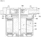
- FIG. 1 is a view illustrating a motor according to an embodiment.
- the motor may include a shaft 100, a rotor 200, a stator 300, a busbar 400, and a wire assembly 500.
- a housing 10 may accommodate the rotor 200 and the stator 300 therein.
- the housing 10 has a cylindrical shape.
- the housing 10 includes an open upper portion.
- a bracket 20 covers the open upper portion of the housing 10.
- the stator 300 is positioned inside the housing 10.
- the rotor 200 may be disposed inside the stator 300.
- the shaft 100 may be coupled to the rotor 200.
- the rotor 200 rotates.
- the shaft 100 rotates in conjunction with the rotator 200.
- the shaft 100 is connected to a steering shaft of a vehicle and transmits power to the steering shaft.
- the rotor 200 is rotated due to an electrical interaction with the stator 300.
- the rotor 200 may include a rotor core and a magnet.
- the rotor core may be formed to have a form in which a plurality of plates having circular thin steel sheet forms are stacked or to have a single barrel form.
- a hole to which the shaft 100 is coupled may be formed at a center of the rotor core.
- a protrusion configured to guide the magnet may protrude from an outer circumferential surface of the rotor core.
- the magnet may be attached to the outer circumferential surface of the rotor core.
- a plurality of magnets may be disposed along a circumference of the rotor core at predetermined intervals.
- the rotor 200 may include a can member which surrounds the magnets to fix the magnets so that the magnets are prevented from being separated from the rotor core and to prevent the magnets from being exposed.
- the stator 300 may include a stator core having a plurality of teeth.
- a yoke portion having a ring shape may be provided, and the teeth around which the coil is wound from the yoke portion in a central direction may be provided.
- the teeth may be provided along an outer circumferential surface of the yoke portion at predetermined intervals.
- the stator core may be formed by mutually stacking the plurality of plates having the thin steel sheet forms.
- the stator core may be formed by mutually coupling or connecting a plurality of separate cores.
- the busbar 400 may be disposed above the stator 300.
- the busbar 400 may include a terminal inside a mold member having a ring shape.
- the wire assembly 500 is connected to the busbar 400 to supply a current thereto.
- a sensing magnet 600 is a device coupled to the shaft 100 to operate in conjunction with the rotor 200 so as to detect a position of the rotor 200.
- a sensor configured to detect a magnetic force of the sensing magnet 600 may be disposed on a printed circuit board 700.
- the sensor may be a Hall integrated circuit (IC).
- the sensor generates a sensing signal by detecting changes of an N pole and an S pole of the sensing magnet 600.
- FIG. 2 is a view illustrating a position of the wire assembly.
- the wire assembly 500 is seated at an upper side of the housing 10.
- the bracket 20 is positioned at an upper side of the wire assembly 500.
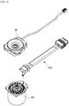
- FIG. 3 is a view illustrating the wire assembly illustrated in FIG. 2 .
- FIG. 4 is a view illustrating cables and first terminals of the wire assembly illustrated in in FIG. 2 .
- the wire assembly 500 may include a grommet 510, cables 520, and first terminals 530.
- the grommet 510 may include a body 511 and an extension 512.
- the body 511 and the extension 512 are only functionally distinguished and may be formed of one material so that the body 511 and the extension 512 are connected to each other.
- the grommet 510 may be formed of an insulating material, and the grommet 510 may be formed of an elastically deformable material.
- the body 511 may include parts of the cables 520 and the first terminals 530.
- the body 511 is a part seated on an upper surface of the housing 10 (see FIG. 2 ).
- the extension 512 is disposed to be connected to a front portion of the body 511.
- the extension 512 surrounds the first terminals 530.
- the extension 512 includes connecting end portions 531 of the first terminals 530.
- the connecting end portions 531 are end portions of the first terminals 530 and are portions connected to the busbar 400.
- the connecting end portion 531 of the first terminal 530 may have a shape bent such as a " " shape.
- the connecting end portion 531 should have a shape curved in a "U” shape for a fusing process, in the case of the motor according to the embodiment, since the fusing process is eliminated, the shape of the connecting end portion 531 may be simplified into the " " shape.
- a cross-sectional shape of the connecting end portion 531 of the first terminal 530 may be a rectangular shape.
- the connecting end portions 531, which have the rectangular cross sections, of the first terminals 530 may be easily inserted into second terminals 410 (see FIG. 7 ).
- the number of the first terminals 530 may be three. Three first terminals 530 are connected to three cables 520. In addition, three first terminals 530 are coupled to the second terminals 410 (see FIG. 7 ) having a U-phase, a V-phase, and a W-phase.
- the extension 512 of the grommet 510 may include insert holes 513.
- the insert holes 513 are disposed to pass through from a lower surface of the grommet 510 to an upper surface thereof.
- positions of the insert holes 513 correspond to positions of the connecting end portions 531 of the first terminals 530.
- the connecting end portions 531 of the first terminals 530 are positioned in the insert holes 513.
- the connecting end portions 531 of the first terminals 530 are exposed to the outside through the insert holes 513.
- the connecting end portions 531 may be positioned at centers of the insert holes 513.
- the second terminals 410 (see FIG. 7 ) of the busbar 400 are inserted into the insert holes 513.
- FIG. 5 is a view illustrating the form of the extension of the grommet.
- a shape of the extension 512 of the grommet 510 corresponds to positions of the first terminals 530.
- the extension 512 may be implemented in various forms to surround all the first terminals 530.
- a front surface of the extension 512 may be a curved surface.
- a radius R1 of a curvature of the front surface of the extension 512 should be at least greater than an outer diameter R2 of the sensing magnet 600 (see FIG. 1 ). This is because the sensing magnet 600 (see FIG. 1 ) is disposed inside the extension 512.
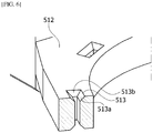
- FIG. 6 is a view illustrating a cross section of the extension for illustrating the insert hole.
- an inlet of the insert hole 513 may have an expanded form. That is, sidewalls 513a and 513b continuing from the upper surface or lower surface of the extension 512 to the insert hole 513 may have inclined forms. The sidewalls 513a and 513b assist the second terminal 410 (see FIG. 7 ) of the busbar 400 to be easily inserted into the insert hole 513 and guide the second terminal 410 (see FIG. 7 ).
- FIG. 7 is a view illustrating the busbar.
- FIG. 8 is a view illustrating the second terminal of the busbar.
- the busbar 400 may include the second terminals 410.
- the second terminals 410 are insertion-coupled to the first terminals 530 of the wire assembly 500 (see FIG. 4 ).
- the second terminal 410 may include a base 411 having a ring shape and three terminals 412, 413, and 414 connected to the base 411.
- the base 411 may be mounted on a mold member of the busbar 400. Any one terminal 412 of three terminals 412, 413, and 414 may be insertion-coupled to the first terminal 530.
- the terminal 412 may include a connector 412a and a clip 412b.
- the connector 412a is connected to a coil 310 wound around the stator 300.
- the connector 412a may have a curved shape such as a "u" shape.
- the clip 412b is connected to the connector 412a.
- the clip 412b is disposed to stand up vertically.
- the clip 412b may include a slot 412c.
- the slot 412c may have a concave form formed from an upper end of the clip 412b toward a lower side thereof.
- the first terminal 530 of the wire assembly 500 (see FIG. 4 ) is inserted into the slot 412c.
- a hooking step 412d is disposed on an inner sidewall of the slot 412c.
- the hooking step 412d has a latch form, and when the first terminal 530 is inserted into the slot 412c once, the first terminal 530 is fixed so as to not be pulled out of the slot 412c.
- a width of the slot 412c is suitably determined by considering a width of the connecting end portion 531 of the first terminal 530 so as to facilitate insertion-coupling.
- FIG. 9 is a view illustrating the first terminal and the second terminal which are insertion-coupled.
- an inlet 412e of the slot 412c may have an inclined form so as to easily insert the connecting end portion 531 thereinto. That is, a width of the inlet of the slot 412c may decrease toward a lower side thereof.
- a size of the insert hole 513 may correspond to a width of the clip 412b.
- a shape of the insert hole 513 may correspond to a shape of the clip 412b.
Landscapes
- Engineering & Computer Science (AREA)
- Power Engineering (AREA)
- Microelectronics & Electronic Packaging (AREA)
- Chemical & Material Sciences (AREA)
- Combustion & Propulsion (AREA)
- Transportation (AREA)
- Mechanical Engineering (AREA)
- Motor Or Generator Frames (AREA)
- Insulation, Fastening Of Motor, Generator Windings (AREA)
- Windings For Motors And Generators (AREA)
Abstract
Description
- The present invention relates to a motor.
- An electric power steering system (EPS) is a system which secures turning stability of a vehicle and rapid restoring force so that a driver can stably drive. The EPS drives a motor to control operation of a steering shaft of the vehicle through an electronic control unit (ECU) according to travel conditions detected by a vehicle speed sensor, a torque angle sensor, and the like.
- The motor includes a rotor and a stator. A coil is wound around the stator. A connecting end portion of the coil wound around the stator may be connected to a busbar. The busbar may include a terminal connected to the connecting end portion of the coil. The terminal of the busbar may be connected to the connecting end portion of the coil wound around the stator and connected to a wire assembly. The wire assembly is connected to an external power source.
- Here, a terminal of the wire assembly is connected to the terminal of the busbar by fusing. However, a fusing process has problems of being a difficult operation, having a high failure rate, and increasing cost. Particularly, since the fusing process is needed for each terminal of three phases, there is a problem in that the number of manufacturing processes is increased.
- The present invention is directed to providing a motor of which a terminal of a wire assembly is connectable to a terminal of a busbar without performing a fusing process.
- Objectives that should be solved according to the embodiments are not limited to the above described objectives, and other objectives which are not described above will be clearly understood by those skilled in the art from the following specification.
- One aspect of the present invention provides a motor including a shaft, a rotor including a hole in which the shaft is disposed, a stator disposed outside the rotor, a busbar disposed above the stator, and a wire assembly connected to the busbar, wherein the wire assembly includes a grommet, a cable of which a part is disposed inside the grommet, and a first terminal connected to the cable. The first terminal includes a connecting end portion, the grommet includes a body having the cable therein and an extension extending from the body and having the first terminal therein, the extension includes an insert hole formed to pass through from a lower surface of the extension to an upper surface of the extension, and the connecting end portion is disposed inside the insert hole.
- The busbar may include a second terminal, and the first terminal and the second terminal are insertion-coupled.
- The second terminal may include a connector connected to a coil wound around the stator and a clip protruding upward from one side of the connector and coupled to the connecting end portion of the first terminal.
- The clip may include a slot which is concavely formed from an upper end of the clip toward a lower side thereof and to which the connecting end portion of the first terminal is insertion-coupled.
- The slot may include a hooking step protruding from a sidewall of the slot and configured to restrict movement of the connecting end portion of the first terminal.
- The second terminal may include a base having a ring shape and a plurality of terminals connected to the base, and any one of the plurality of terminals may include the clip.
- The clip may be disposed inside the insert hole.
- The connecting end portion of the first terminal may have a shape bent such as a "" shape.

- The motor may further include a a sensing magnet coupled to the shaft, wherein a front surface of the extension may be a curved surface, and a radius of a curvature of the front surface of the extension may be greater than an outer diameter of the sensing magnet.
- An upper surface or a lower surface of the insert hole may include a sidewall having an inclined shape.
- A width of an inlet of the slot may decrease toward a lower side thereof.
- According to an embodiment, since a terminal of a wire assembly is connected to a terminal of a busbar through an insertion coupling method without performing a fusing process, there are advantageous effects in that assembly or reassembly is facilitated and a manufacturing cost is reduced.
- Particularly, since busbar terminals of three phases are connected to the wire assembly through one insertion coupling process, there is an advantageous effect in that a manufacturing process is significantly simplified.
-
-
FIG. 1 is a view illustrating a motor according to an embodiment. -
FIG. 2 is a view illustrating a position of a wire assembly. -
FIG. 3 is a view illustrating the wire assembly illustrated inFIG. 2 . -
FIG. 4 is a view illustrating cables and first terminals of the wire assembly illustrated in inFIG. 2 . -
FIG. 5 is a view illustrating the form of an extension of a grommet. -
FIG. 6 is a view illustrating a cross section of the extension for illustrating the insert hole. -
FIG. 7 is a view illustrating a busbar. -
FIG. 8 is a view illustrating a second terminal of the busbar. -
FIG. 9 is a view illustrating the first terminal and the second terminal which are insertion-coupled. - Hereinafter, exemplary embodiments of the present invention will be described with reference to the accompanying drawings in detail. Purposes, specific advantages, and novel features of the invention will be made clear from the exemplary embodiments and the following detailed description in connection with the accompanying drawings. Terms and words used in this specification and claims are not to be interpreted as limited to commonly used meanings or meanings in dictionaries and should be interpreted as having meanings and concepts which are consistent with the technological scope of the invention based on the principle that the inventors have appropriately defined concepts of terms in order to describe the invention in the best way. In the description of the invention, when it is determined that detailed descriptions of related well-known functions unnecessarily obscure the gist of the invention, the detailed descriptions thereof will be omitted.
- It will be understood that, although the terms "first," "second," etc. may be used herein to describe various elements, these elements should not be limited by these terms. These terms are only used to distinguish one element from another. For example, a first element could be termed a second element, and a second element could similarly be termed a first element without departing from the scope of the present invention. As used herein, the term "and/or" includes combinations or any one of a plurality of associated listed items.
-
FIG. 1 is a view illustrating a motor according to an embodiment. - Referring to
FIG. 1 , the motor according to the embodiment may include ashaft 100, arotor 200, astator 300, abusbar 400, and awire assembly 500. - A
housing 10 may accommodate therotor 200 and thestator 300 therein. Thehousing 10 has a cylindrical shape. In addition, thehousing 10 includes an open upper portion. Abracket 20 covers the open upper portion of thehousing 10. Thestator 300 is positioned inside thehousing 10. In addition, therotor 200 may be disposed inside thestator 300. - The
shaft 100 may be coupled to therotor 200. When an electromagnetic interaction between therotor 200 and thestator 300 occurs by supplying a current, therotor 200 rotates. In addition, theshaft 100 rotates in conjunction with therotator 200. Theshaft 100 is connected to a steering shaft of a vehicle and transmits power to the steering shaft. - The
rotor 200 is rotated due to an electrical interaction with thestator 300. - The
rotor 200 may include a rotor core and a magnet. The rotor core may be formed to have a form in which a plurality of plates having circular thin steel sheet forms are stacked or to have a single barrel form. A hole to which theshaft 100 is coupled may be formed at a center of the rotor core. A protrusion configured to guide the magnet may protrude from an outer circumferential surface of the rotor core. The magnet may be attached to the outer circumferential surface of the rotor core. A plurality of magnets may be disposed along a circumference of the rotor core at predetermined intervals. Therotor 200 may include a can member which surrounds the magnets to fix the magnets so that the magnets are prevented from being separated from the rotor core and to prevent the magnets from being exposed. - A coil may be wound around the
stator 300 such that an electrical interaction with therotor 200 may occur. A specific structure of thestator 300 for winding the coil will be described below. Thestator 300 may include a stator core having a plurality of teeth. In the stator core, a yoke portion having a ring shape may be provided, and the teeth around which the coil is wound from the yoke portion in a central direction may be provided. The teeth may be provided along an outer circumferential surface of the yoke portion at predetermined intervals. Meanwhile, the stator core may be formed by mutually stacking the plurality of plates having the thin steel sheet forms. In addition, the stator core may be formed by mutually coupling or connecting a plurality of separate cores. - The
busbar 400 may be disposed above thestator 300. Thebusbar 400 may include a terminal inside a mold member having a ring shape. - The
wire assembly 500 is connected to thebusbar 400 to supply a current thereto. - A
sensing magnet 600 is a device coupled to theshaft 100 to operate in conjunction with therotor 200 so as to detect a position of therotor 200. - A sensor configured to detect a magnetic force of the
sensing magnet 600 may be disposed on a printedcircuit board 700. Here, the sensor may be a Hall integrated circuit (IC). The sensor generates a sensing signal by detecting changes of an N pole and an S pole of thesensing magnet 600. -
FIG. 2 is a view illustrating a position of the wire assembly. - Referring to
FIG. 2 , thewire assembly 500 is seated at an upper side of thehousing 10. In addition, thebracket 20 is positioned at an upper side of thewire assembly 500. -
FIG. 3 is a view illustrating the wire assembly illustrated inFIG. 2 . -
FIG. 4 is a view illustrating cables and first terminals of the wire assembly illustrated in inFIG. 2 . - Referring to
FIGS. 3 and4 , thewire assembly 500 may include agrommet 510,cables 520, andfirst terminals 530. - The
grommet 510 may include abody 511 and anextension 512. Thebody 511 and theextension 512 are only functionally distinguished and may be formed of one material so that thebody 511 and theextension 512 are connected to each other. Thegrommet 510 may be formed of an insulating material, and thegrommet 510 may be formed of an elastically deformable material. - The
body 511 may include parts of thecables 520 and thefirst terminals 530. Thebody 511 is a part seated on an upper surface of the housing 10 (seeFIG. 2 ). Theextension 512 is disposed to be connected to a front portion of thebody 511. Theextension 512 surrounds thefirst terminals 530. Particularly, theextension 512 includes connectingend portions 531 of thefirst terminals 530. Here, the connectingend portions 531 are end portions of thefirst terminals 530 and are portions connected to thebusbar 400. - Referring to
FIG. 4 , the connectingend portion 531 of thefirst terminal 530 may have a shape bent such as a "" shape. Although the connectingend portion 531 should have a shape curved in a "U" shape for a fusing process, in the case of the motor according to the embodiment, since the fusing process is eliminated, the shape of the connectingend portion 531 may be simplified into the "" shape. A cross-sectional shape of the connectingend portion 531 of thefirst terminal 530 may be a rectangular shape. The connectingend portions 531, which have the rectangular cross sections, of thefirst terminals 530 may be easily inserted into second terminals 410 (seeFIG. 7 ). - The number of the
first terminals 530 may be three. Threefirst terminals 530 are connected to threecables 520. In addition, threefirst terminals 530 are coupled to the second terminals 410 (seeFIG. 7 ) having a U-phase, a V-phase, and a W-phase. - The
extension 512 of thegrommet 510 may include insert holes 513. The insert holes 513 are disposed to pass through from a lower surface of thegrommet 510 to an upper surface thereof. In addition, positions of the insert holes 513 correspond to positions of the connectingend portions 531 of thefirst terminals 530. Accordingly, the connectingend portions 531 of thefirst terminals 530 are positioned in the insert holes 513. In addition, the connectingend portions 531 of thefirst terminals 530 are exposed to the outside through the insert holes 513. The connectingend portions 531 may be positioned at centers of the insert holes 513. The second terminals 410 (seeFIG. 7 ) of thebusbar 400 are inserted into the insert holes 513. -
FIG. 5 is a view illustrating the form of the extension of the grommet. - Referring to
FIG. 5 , a shape of theextension 512 of thegrommet 510 corresponds to positions of thefirst terminals 530. Theextension 512 may be implemented in various forms to surround all thefirst terminals 530. A front surface of theextension 512 may be a curved surface. Here, based on a rotation center C of the motor, a radius R1 of a curvature of the front surface of theextension 512 should be at least greater than an outer diameter R2 of the sensing magnet 600 (seeFIG. 1 ). This is because the sensing magnet 600 (seeFIG. 1 ) is disposed inside theextension 512. -
FIG. 6 is a view illustrating a cross section of the extension for illustrating the insert hole. - Referring to
FIG. 6 , an inlet of theinsert hole 513 may have an expanded form. That is, sidewalls 513a and 513b continuing from the upper surface or lower surface of theextension 512 to theinsert hole 513 may have inclined forms. Thesidewalls FIG. 7 ) of thebusbar 400 to be easily inserted into theinsert hole 513 and guide the second terminal 410 (seeFIG. 7 ). -
FIG. 7 is a view illustrating the busbar. -
FIG. 8 is a view illustrating the second terminal of the busbar. - Referring to
FIGS. 7 and8 , thebusbar 400 may include thesecond terminals 410. Thesecond terminals 410 are insertion-coupled to thefirst terminals 530 of the wire assembly 500 (seeFIG. 4 ). Thesecond terminal 410 may include a base 411 having a ring shape and threeterminals base 411. The base 411 may be mounted on a mold member of thebusbar 400. Any oneterminal 412 of threeterminals first terminal 530. - The terminal 412 may include a
connector 412a and aclip 412b. - The
connector 412a is connected to acoil 310 wound around thestator 300. Theconnector 412a may have a curved shape such as a "u" shape. Theclip 412b is connected to theconnector 412a. In addition, theclip 412b is disposed to stand up vertically. In addition, theclip 412b may include aslot 412c. Theslot 412c may have a concave form formed from an upper end of theclip 412b toward a lower side thereof. Thefirst terminal 530 of the wire assembly 500 (seeFIG. 4 ) is inserted into theslot 412c. A hookingstep 412d is disposed on an inner sidewall of theslot 412c. The hookingstep 412d has a latch form, and when thefirst terminal 530 is inserted into theslot 412c once, thefirst terminal 530 is fixed so as to not be pulled out of theslot 412c. A width of theslot 412c is suitably determined by considering a width of the connectingend portion 531 of thefirst terminal 530 so as to facilitate insertion-coupling. -
FIG. 9 is a view illustrating the first terminal and the second terminal which are insertion-coupled. - Referring to
FIGS. 3 and9 , when theclip 412b of thesecond terminal 410 is inserted into theinsert hole 513 of thegrommet 510, a lower end of the connectingend portion 531 is inserted into theslot 412c first. In this case, theinsert hole 513 guides theclip 412b. When the connectingend portion 531 is completely inserted into theslot 412c, theclip 412b is fixed so as to not be pulled out of theinsert hole 513 by the hookingstep 412d having the latch form. Here, since theclip 412b of each of thesecond terminals 410 having the U-phase, the V-phase, and the W-phase is inserted into theinsert hole 513 through one coupling process, the number of manufacturing processes can be significantly reduced. - Meanwhile, an
inlet 412e of theslot 412c may have an inclined form so as to easily insert the connectingend portion 531 thereinto. That is, a width of the inlet of theslot 412c may decrease toward a lower side thereof. A size of theinsert hole 513 may correspond to a width of theclip 412b. In addition, a shape of theinsert hole 513 may correspond to a shape of theclip 412b. - As described above, a motor according to one exemplary embodiment of the present invention has been specifically described with respect to the accompanying drawings.
- The above-described embodiments should be considered in a descriptive sense only and not for purposes of limitation. The scope of the present invention is defined not by the detailed description but by the appended claims and encompasses all modifications and alterations derived from meanings and the scope and equivalents of the appended claims.
Claims (10)
- A motor comprising:a stator;a rotor disposed inside the stator;a shaft coupled to the rotor;a busbar disposed above the stator; anda wire assembly connected to the busbar,wherein the wire assembly includes a grommet, a cable of which a part is disposed inside the grommet, and a first terminal connected to the cable,the first terminal includes a connecting end portion,the grommet includes a body having the cable therein and an extension extending from the body and having the first terminal therein,the extension includes an insert hole formed to pass through from a lower surface of the extension to an upper surface of the extension, andthe connecting end portion is disposed inside the insert hole.
- The motor of claim 1, wherein:the busbar includes a second terminal; andthe first terminal and the second terminal are insertion-coupled.
- The motor of claim 2, wherein the second terminal includes a connector connected to a coil wound around the stator and a clip protruding upward from one side of the connector and coupled to the connecting end portion of the first terminal.
- The motor of claim 3, wherein the clip includes a slot which is concavely formed from an upper end of the clip toward a lower side thereof and to which the connecting end portion of the first terminal is insertion-coupled.
- The motor of claim 4, wherein the slot includes a hooking step protruding from a sidewall of the slot and configured to restrict movement of the connecting end portion of the first terminal.
- The motor of claim 3, wherein:the second terminal includes a base having a ring shape and a plurality of terminals connected to the base; andany one of the plurality of terminals includes the clip.
- The motor of claim 3, wherein the clip is disposed inside the insert hole.
- The motor of claim 1, further comprising a sensing magnet coupled to the shaft,
wherein a front surface of the extension is a curved surface, and a radius of a curvature of the front surface of the extension is greater than an outer diameter of the sensing magnet. - The motor of claim 1, wherein an upper surface or a lower surface of the insert hole includes a sidewall having an inclined shape.
- The motor of claim 3, wherein a width of an inlet of the slot decreases toward a lower side thereof.
Applications Claiming Priority (2)
| Application Number | Priority Date | Filing Date | Title |
|---|---|---|---|
| KR1020170053858A KR102343086B1 (en) | 2017-04-26 | 2017-04-26 | Motor |
| PCT/KR2018/004675 WO2018199573A1 (en) | 2017-04-26 | 2018-04-23 | Motor |
Publications (2)
| Publication Number | Publication Date |
|---|---|
| EP3618238A1 true EP3618238A1 (en) | 2020-03-04 |
| EP3618238A4 EP3618238A4 (en) | 2021-01-06 |
Family
ID=63920284
Family Applications (1)
| Application Number | Title | Priority Date | Filing Date |
|---|---|---|---|
| EP18790386.9A Pending EP3618238A4 (en) | 2017-04-26 | 2018-04-23 | ENGINE |
Country Status (6)
| Country | Link |
|---|---|
| US (1) | US11245303B2 (en) |
| EP (1) | EP3618238A4 (en) |
| JP (1) | JP7252903B2 (en) |
| KR (1) | KR102343086B1 (en) |
| CN (1) | CN110574259B (en) |
| WO (1) | WO2018199573A1 (en) |
Families Citing this family (11)
| Publication number | Priority date | Publication date | Assignee | Title |
|---|---|---|---|---|
| KR102343086B1 (en) * | 2017-04-26 | 2021-12-24 | 엘지이노텍 주식회사 | Motor |
| CN109256884A (en) * | 2017-10-13 | 2019-01-22 | 朱卫 | A kind of motor case produced with titanium |
| KR102715312B1 (en) * | 2018-12-04 | 2024-10-11 | 엘지이노텍 주식회사 | Motor |
| CN114556755B (en) * | 2019-10-10 | 2023-07-14 | Lg伊诺特有限公司 | Motor |
| JP6995102B2 (en) * | 2019-11-01 | 2022-01-14 | 三菱電機株式会社 | Rotating machine and manufacturing method of rotating machine |
| WO2021172770A1 (en) * | 2020-02-24 | 2021-09-02 | 엘지이노텍 주식회사 | Motor |
| KR102354811B1 (en) * | 2020-06-05 | 2022-01-25 | 주식회사 씨앤엠 | power supply unit for compressor installed in hydrogen fuel vehicle |
| CN115769473B (en) * | 2020-07-03 | 2026-04-28 | Lg伊诺特有限公司 | Busbar and motor including busbar |
| KR102603313B1 (en) * | 2021-05-28 | 2023-11-17 | 주식회사 씨앤엠 | stator insulation structure for air-compressor |
| CN115189500A (en) * | 2021-11-11 | 2022-10-14 | 尼得科电机(青岛)有限公司 | Motor |
| EP4597801A1 (en) * | 2024-01-30 | 2025-08-06 | Hilti Aktiengesellschaft | Multi-terminal stator |
Family Cites Families (29)
| Publication number | Priority date | Publication date | Assignee | Title |
|---|---|---|---|---|
| JPH07335302A (en) * | 1994-06-08 | 1995-12-22 | Amp Japan Ltd | Connector |
| JPH10155253A (en) * | 1996-11-22 | 1998-06-09 | Mitsumi Electric Co Ltd | Small motor |
| JP2002281704A (en) * | 2001-03-16 | 2002-09-27 | Nippon Densan Corp | Coil assembly part structure for motor |
| DE20212273U1 (en) * | 2002-03-08 | 2003-07-24 | ebm Werke GmbH & Co. KG, 74673 Mulfingen | Stator for an electric motor has coil winding connector blocks fitting on stator edge. |
| CN101258067A (en) * | 2005-09-01 | 2008-09-03 | 日本精工株式会社 | Electric Steering |
| US20070145838A1 (en) * | 2005-12-07 | 2007-06-28 | Nidec Corporation | Motor and Method of Manufacturing Housing |
| DE202006012075U1 (en) * | 2006-08-04 | 2007-12-27 | Ebm-Papst Mulfingen Gmbh & Co. Kg | Stator with switching disc |
| JP2008311219A (en) * | 2007-05-14 | 2008-12-25 | Mitsuba Corp | Bonding structure of electric connection terminal and electric motor provided with electric connection terminal |
| JP5028220B2 (en) | 2007-10-31 | 2012-09-19 | 日立オートモティブシステムズ株式会社 | Electric power steering motor, electromagnetic shield structure and electromagnetic shield method used therefor |
| AU2009345022B2 (en) * | 2009-04-22 | 2014-02-13 | Mitsubishi Electric Corporation | Motor and electric apparatus and method for manufacturing motor |
| KR101049785B1 (en) | 2009-11-03 | 2011-07-19 | 주식회사 삼현 | Fan motor for controller type with bus bar winding structure stator |
| JP2011131775A (en) * | 2009-12-25 | 2011-07-07 | Nsk Ltd | Electric power steering device with control device and dynamo-electric machine |
| WO2011108181A2 (en) * | 2010-03-02 | 2011-09-09 | Panasonic Corporation | Electric motor, electric motor unit, blower, and electric device |
| JP5622415B2 (en) * | 2010-03-29 | 2014-11-12 | 本田技研工業株式会社 | Joint connector |
| JP2013042633A (en) * | 2011-08-19 | 2013-02-28 | Nippon Densan Corp | Motor |
| JP5452570B2 (en) | 2011-11-09 | 2014-03-26 | 三菱電機株式会社 | Rotating electric machine and method of manufacturing stator coil connection unit |
| JP5467376B1 (en) * | 2012-06-04 | 2014-04-09 | パナソニック株式会社 | Method for forming electrical connection structure, method for manufacturing aluminum wire with terminal, electrical connection structure and motor including the same, electric device including the motor, aluminum wire with terminal, motor including the same, and motor Electrical equipment with |
| US9444311B2 (en) * | 2012-08-28 | 2016-09-13 | Mitsubishi Electric Corporation | Electric driving device and method for manufacturing electric driving device |
| JP6053002B2 (en) * | 2013-03-08 | 2016-12-27 | Kyb株式会社 | Bus bar unit |
| WO2014171006A1 (en) * | 2013-04-19 | 2014-10-23 | 三菱電機株式会社 | Dynamo-electric machine |
| JP2014236615A (en) * | 2013-06-04 | 2014-12-15 | 三菱電機株式会社 | Dynamo-electric machine with built-in controller |
| US10003235B2 (en) * | 2014-01-08 | 2018-06-19 | Continental Automotive Systems, Inc. | Flexible connector system for connecting a high current motor to a PCB of an integrated electronics system of a vehicle |
| KR102118030B1 (en) * | 2014-01-29 | 2020-06-02 | 엘지이노텍 주식회사 | Connector and Motor having the same |
| KR102212950B1 (en) | 2015-01-07 | 2021-02-05 | 엘지이노텍 주식회사 | Motor |
| EP3284160A1 (en) * | 2015-04-15 | 2018-02-21 | Schaeffler Technologies AG & Co. KG | Actuator for a motor vehicle clutch, comprising a support with a plug held therein, and hybrid module comprising such an actuator |
| JP6638295B2 (en) * | 2015-09-30 | 2020-01-29 | アイシン精機株式会社 | Rotating electric machine |
| EP3493376B1 (en) * | 2016-08-01 | 2021-07-28 | LG Innotek Co., Ltd. | Rear holder and motor comprising same |
| KR102343086B1 (en) * | 2017-04-26 | 2021-12-24 | 엘지이노텍 주식회사 | Motor |
| DE102019100020A1 (en) * | 2019-01-02 | 2020-07-02 | Nidec Corporation | Electric motor with busbar unit |
-
2017
- 2017-04-26 KR KR1020170053858A patent/KR102343086B1/en active Active
-
2018
- 2018-04-23 EP EP18790386.9A patent/EP3618238A4/en active Pending
- 2018-04-23 US US16/608,988 patent/US11245303B2/en active Active
- 2018-04-23 JP JP2019557418A patent/JP7252903B2/en active Active
- 2018-04-23 WO PCT/KR2018/004675 patent/WO2018199573A1/en not_active Ceased
- 2018-04-23 CN CN201880028462.0A patent/CN110574259B/en active Active
Also Published As
| Publication number | Publication date |
|---|---|
| EP3618238A4 (en) | 2021-01-06 |
| KR102343086B1 (en) | 2021-12-24 |
| CN110574259B (en) | 2022-01-28 |
| JP2020518220A (en) | 2020-06-18 |
| WO2018199573A1 (en) | 2018-11-01 |
| JP7252903B2 (en) | 2023-04-05 |
| CN110574259A (en) | 2019-12-13 |
| US20200220414A1 (en) | 2020-07-09 |
| US11245303B2 (en) | 2022-02-08 |
| KR20180119997A (en) | 2018-11-05 |
Similar Documents
| Publication | Publication Date | Title |
|---|---|---|
| US11245303B2 (en) | Motor including a busbar and a wire assembly | |
| KR102353916B1 (en) | Terminal asembly for motor and Motor using the same | |
| US11843296B2 (en) | Motor and air conditioner | |
| CN107492961B (en) | Rotor and motor having the same | |
| KR101565364B1 (en) | Method and structure for mounting sensor substrate of brushless motor | |
| US20220190692A1 (en) | Drive device having a brushless electric motor | |
| EP3681017A1 (en) | Motor | |
| US11394267B2 (en) | Motor | |
| EP3051637A1 (en) | Motor | |
| JP7432706B2 (en) | Brushless DC electric motor for automotive wiper system | |
| CN109769403B (en) | Rear holder and motor including the same | |
| CN111344934B (en) | Rotating electrical machine | |
| JP6306479B2 (en) | Motor unit | |
| US12237749B2 (en) | Motor unit | |
| JP6488100B2 (en) | Electric motor | |
| CN113330666B (en) | Pump comprising an electric motor with a plug-in connection in the form of an intermediate plug-in part | |
| KR102690869B1 (en) | Motor | |
| JP2006352979A (en) | Rotating electric machine | |
| US6759773B1 (en) | Electronically controlled electric motor provided for use in an environment containing solvents | |
| KR20190093352A (en) | Motor | |
| KR20110099827A (en) | Step motor | |
| KR20210090006A (en) | Rotor and motorhaving the same |
Legal Events
| Date | Code | Title | Description |
|---|---|---|---|
| STAA | Information on the status of an ep patent application or granted ep patent |
Free format text: STATUS: THE INTERNATIONAL PUBLICATION HAS BEEN MADE |
|
| PUAI | Public reference made under article 153(3) epc to a published international application that has entered the european phase |
Free format text: ORIGINAL CODE: 0009012 |
|
| STAA | Information on the status of an ep patent application or granted ep patent |
Free format text: STATUS: REQUEST FOR EXAMINATION WAS MADE |
|
| 17P | Request for examination filed |
Effective date: 20191024 |
|
| AK | Designated contracting states |
Kind code of ref document: A1 Designated state(s): AL AT BE BG CH CY CZ DE DK EE ES FI FR GB GR HR HU IE IS IT LI LT LU LV MC MK MT NL NO PL PT RO RS SE SI SK SM TR |
|
| AX | Request for extension of the european patent |
Extension state: BA ME |
|
| DAV | Request for validation of the european patent (deleted) | ||
| DAX | Request for extension of the european patent (deleted) | ||
| A4 | Supplementary search report drawn up and despatched |
Effective date: 20201204 |
|
| RIC1 | Information provided on ipc code assigned before grant |
Ipc: H02K 29/08 20060101ALI20201130BHEP Ipc: H02K 3/48 20060101ALI20201130BHEP Ipc: B62D 5/04 20060101ALI20201130BHEP Ipc: H02K 5/22 20060101ALI20201130BHEP Ipc: H02K 3/12 20060101ALI20201130BHEP Ipc: H02K 1/16 20060101ALI20201130BHEP Ipc: H02K 11/215 20160101ALI20201130BHEP Ipc: H02K 3/52 20060101ALI20201130BHEP Ipc: H02K 11/20 20160101ALI20201130BHEP Ipc: H02K 3/38 20060101AFI20201130BHEP |
|
| STAA | Information on the status of an ep patent application or granted ep patent |
Free format text: STATUS: EXAMINATION IS IN PROGRESS |
|
| 17Q | First examination report despatched |
Effective date: 20230227 |
|
| GRAP | Despatch of communication of intention to grant a patent |
Free format text: ORIGINAL CODE: EPIDOSNIGR1 |
|
| STAA | Information on the status of an ep patent application or granted ep patent |
Free format text: STATUS: GRANT OF PATENT IS INTENDED |