EP3618156A1 - Battery member for secondary battery, secondary battery, and production methods therefor - Google Patents
Battery member for secondary battery, secondary battery, and production methods therefor Download PDFInfo
- Publication number
- EP3618156A1 EP3618156A1 EP18790992.4A EP18790992A EP3618156A1 EP 3618156 A1 EP3618156 A1 EP 3618156A1 EP 18790992 A EP18790992 A EP 18790992A EP 3618156 A1 EP3618156 A1 EP 3618156A1
- Authority
- EP
- European Patent Office
- Prior art keywords
- mixture layer
- electrode mixture
- positive electrode
- negative electrode
- electrolyte
- Prior art date
- Legal status (The legal status is an assumption and is not a legal conclusion. Google has not performed a legal analysis and makes no representation as to the accuracy of the status listed.)
- Withdrawn
Links
- 238000004519 manufacturing process Methods 0.000 title claims description 12
- 239000000203 mixture Substances 0.000 claims abstract description 208
- 239000003792 electrolyte Substances 0.000 claims abstract description 119
- 239000002608 ionic liquid Substances 0.000 claims abstract description 60
- 239000007772 electrode material Substances 0.000 claims abstract description 9
- 239000002245 particle Substances 0.000 claims description 49
- -1 pyrrolidinium cation Chemical class 0.000 claims description 40
- 229920000642 polymer Polymers 0.000 claims description 35
- 150000003839 salts Chemical class 0.000 claims description 29
- 229910003002 lithium salt Inorganic materials 0.000 claims description 15
- 239000007773 negative electrode material Substances 0.000 claims description 14
- 239000007774 positive electrode material Substances 0.000 claims description 14
- BQCIDUSAKPWEOX-UHFFFAOYSA-N 1,1-Difluoroethene Chemical compound FC(F)=C BQCIDUSAKPWEOX-UHFFFAOYSA-N 0.000 claims description 10
- 159000000002 lithium salts Chemical class 0.000 claims description 10
- 229910014332 N(SO2CF3)2 Inorganic materials 0.000 claims description 9
- 229910014351 N(SO2F)2 Inorganic materials 0.000 claims description 9
- HCDGVLDPFQMKDK-UHFFFAOYSA-N hexafluoropropylene Chemical group FC(F)=C(F)C(F)(F)F HCDGVLDPFQMKDK-UHFFFAOYSA-N 0.000 claims description 9
- 159000000007 calcium salts Chemical class 0.000 claims description 7
- 159000000003 magnesium salts Chemical class 0.000 claims description 7
- 159000000000 sodium salts Chemical class 0.000 claims description 7
- 229910016855 F9SO2 Inorganic materials 0.000 claims description 6
- 125000000129 anionic group Chemical group 0.000 claims description 6
- 229910052757 nitrogen Inorganic materials 0.000 claims description 6
- BFKJFAAPBSQJPD-UHFFFAOYSA-N tetrafluoroethene Chemical group FC(F)=C(F)F BFKJFAAPBSQJPD-UHFFFAOYSA-N 0.000 claims description 6
- SMZOUWXMTYCWNB-UHFFFAOYSA-N 2-(2-methoxy-5-methylphenyl)ethanamine Chemical compound COC1=CC=C(C)C=C1CCN SMZOUWXMTYCWNB-UHFFFAOYSA-N 0.000 claims description 5
- NIXOWILDQLNWCW-UHFFFAOYSA-N 2-Propenoic acid Natural products OC(=O)C=C NIXOWILDQLNWCW-UHFFFAOYSA-N 0.000 claims description 5
- RAXXELZNTBOGNW-UHFFFAOYSA-O Imidazolium Chemical compound C1=C[NH+]=CN1 RAXXELZNTBOGNW-UHFFFAOYSA-O 0.000 claims description 5
- VVQNEPGJFQJSBK-UHFFFAOYSA-N Methyl methacrylate Chemical compound COC(=O)C(C)=C VVQNEPGJFQJSBK-UHFFFAOYSA-N 0.000 claims description 5
- NQRYJNQNLNOLGT-UHFFFAOYSA-O Piperidinium(1+) Chemical compound C1CC[NH2+]CC1 NQRYJNQNLNOLGT-UHFFFAOYSA-O 0.000 claims description 5
- OFOBLEOULBTSOW-UHFFFAOYSA-N Propanedioic acid Natural products OC(=O)CC(O)=O OFOBLEOULBTSOW-UHFFFAOYSA-N 0.000 claims description 5
- 125000002091 cationic group Chemical group 0.000 claims description 5
- 150000001768 cations Chemical class 0.000 claims description 5
- SUPCQIBBMFXVTL-UHFFFAOYSA-N ethyl 2-methylprop-2-enoate Chemical compound CCOC(=O)C(C)=C SUPCQIBBMFXVTL-UHFFFAOYSA-N 0.000 claims description 5
- VZCYOOQTPOCHFL-UPHRSURJSA-N maleic acid Chemical compound OC(=O)\C=C/C(O)=O VZCYOOQTPOCHFL-UPHRSURJSA-N 0.000 claims description 5
- 239000011976 maleic acid Substances 0.000 claims description 5
- JUJWROOIHBZHMG-UHFFFAOYSA-O pyridinium Chemical compound C1=CC=[NH+]C=C1 JUJWROOIHBZHMG-UHFFFAOYSA-O 0.000 claims description 5
- VZCYOOQTPOCHFL-UHFFFAOYSA-N trans-butenedioic acid Natural products OC(=O)C=CC(O)=O VZCYOOQTPOCHFL-UHFFFAOYSA-N 0.000 claims description 5
- 238000003825 pressing Methods 0.000 description 33
- 229910052744 lithium Inorganic materials 0.000 description 19
- 239000011777 magnesium Substances 0.000 description 18
- 239000011575 calcium Substances 0.000 description 16
- WHXSMMKQMYFTQS-UHFFFAOYSA-N Lithium Chemical compound [Li] WHXSMMKQMYFTQS-UHFFFAOYSA-N 0.000 description 15
- 125000000217 alkyl group Chemical group 0.000 description 15
- 125000004432 carbon atom Chemical group C* 0.000 description 15
- VYPSYNLAJGMNEJ-UHFFFAOYSA-N Silicium dioxide Chemical compound O=[Si]=O VYPSYNLAJGMNEJ-UHFFFAOYSA-N 0.000 description 12
- 238000000034 method Methods 0.000 description 12
- 229910052782 aluminium Inorganic materials 0.000 description 11
- 239000006258 conductive agent Substances 0.000 description 11
- 238000002360 preparation method Methods 0.000 description 11
- 239000011230 binding agent Substances 0.000 description 9
- 150000001875 compounds Chemical class 0.000 description 9
- XAGFODPZIPBFFR-UHFFFAOYSA-N aluminium Chemical compound [Al] XAGFODPZIPBFFR-UHFFFAOYSA-N 0.000 description 8
- 239000011734 sodium Substances 0.000 description 8
- 229910052802 copper Inorganic materials 0.000 description 7
- 239000010949 copper Substances 0.000 description 7
- 238000001035 drying Methods 0.000 description 7
- 229910021437 lithium-transition metal oxide Inorganic materials 0.000 description 7
- 229910052751 metal Inorganic materials 0.000 description 7
- 239000002184 metal Substances 0.000 description 7
- 229920001343 polytetrafluoroethylene Polymers 0.000 description 7
- 239000004810 polytetrafluoroethylene Substances 0.000 description 7
- OKTJSMMVPCPJKN-UHFFFAOYSA-N Carbon Chemical compound [C] OKTJSMMVPCPJKN-UHFFFAOYSA-N 0.000 description 6
- RYGMFSIKBFXOCR-UHFFFAOYSA-N Copper Chemical compound [Cu] RYGMFSIKBFXOCR-UHFFFAOYSA-N 0.000 description 6
- 229920001577 copolymer Polymers 0.000 description 6
- 239000000463 material Substances 0.000 description 6
- 125000004183 alkoxy alkyl group Chemical group 0.000 description 5
- 229910052681 coesite Inorganic materials 0.000 description 5
- 229910052906 cristobalite Inorganic materials 0.000 description 5
- 239000008151 electrolyte solution Substances 0.000 description 5
- 125000001495 ethyl group Chemical group [H]C([H])([H])C([H])([H])* 0.000 description 5
- QSHDDOUJBYECFT-UHFFFAOYSA-N mercury Chemical compound [Hg] QSHDDOUJBYECFT-UHFFFAOYSA-N 0.000 description 5
- 229910052753 mercury Inorganic materials 0.000 description 5
- 125000002496 methyl group Chemical group [H]C([H])([H])* 0.000 description 5
- 125000001624 naphthyl group Chemical group 0.000 description 5
- PXHVJJICTQNCMI-UHFFFAOYSA-N nickel Substances [Ni] PXHVJJICTQNCMI-UHFFFAOYSA-N 0.000 description 5
- 125000001997 phenyl group Chemical group [H]C1=C([H])C([H])=C(*)C([H])=C1[H] 0.000 description 5
- 239000000377 silicon dioxide Substances 0.000 description 5
- 229910052682 stishovite Inorganic materials 0.000 description 5
- 229910052905 tridymite Inorganic materials 0.000 description 5
- XLOMVQKBTHCTTD-UHFFFAOYSA-N Zinc monoxide Chemical compound [Zn]=O XLOMVQKBTHCTTD-UHFFFAOYSA-N 0.000 description 4
- 229910045601 alloy Inorganic materials 0.000 description 4
- 239000000956 alloy Substances 0.000 description 4
- 229910001914 chlorine tetroxide Inorganic materials 0.000 description 4
- 239000011248 coating agent Substances 0.000 description 4
- 238000000576 coating method Methods 0.000 description 4
- 239000002612 dispersion medium Substances 0.000 description 4
- 229910052749 magnesium Inorganic materials 0.000 description 4
- 238000002156 mixing Methods 0.000 description 4
- 229910052759 nickel Inorganic materials 0.000 description 4
- VLTRZXGMWDSKGL-UHFFFAOYSA-M perchlorate Chemical compound [O-]Cl(=O)(=O)=O VLTRZXGMWDSKGL-UHFFFAOYSA-M 0.000 description 4
- 239000002002 slurry Substances 0.000 description 4
- 239000007784 solid electrolyte Substances 0.000 description 4
- 239000000243 solution Substances 0.000 description 4
- 239000010935 stainless steel Substances 0.000 description 4
- 229910001220 stainless steel Inorganic materials 0.000 description 4
- 229910052719 titanium Inorganic materials 0.000 description 4
- 239000010936 titanium Substances 0.000 description 4
- 229910052723 transition metal Inorganic materials 0.000 description 4
- 229910001290 LiPF6 Inorganic materials 0.000 description 3
- OKKJLVBELUTLKV-UHFFFAOYSA-N Methanol Chemical compound OC OKKJLVBELUTLKV-UHFFFAOYSA-N 0.000 description 3
- RTAQQCXQSZGOHL-UHFFFAOYSA-N Titanium Chemical compound [Ti] RTAQQCXQSZGOHL-UHFFFAOYSA-N 0.000 description 3
- 239000006230 acetylene black Substances 0.000 description 3
- 239000003575 carbonaceous material Substances 0.000 description 3
- 229910002804 graphite Inorganic materials 0.000 description 3
- 239000010439 graphite Substances 0.000 description 3
- 238000010438 heat treatment Methods 0.000 description 3
- 239000005001 laminate film Substances 0.000 description 3
- 238000003475 lamination Methods 0.000 description 3
- MHCFAGZWMAWTNR-UHFFFAOYSA-M lithium perchlorate Chemical compound [Li+].[O-]Cl(=O)(=O)=O MHCFAGZWMAWTNR-UHFFFAOYSA-M 0.000 description 3
- 229910001486 lithium perchlorate Inorganic materials 0.000 description 3
- 229910001496 lithium tetrafluoroborate Inorganic materials 0.000 description 3
- 229910052748 manganese Inorganic materials 0.000 description 3
- 150000003624 transition metals Chemical class 0.000 description 3
- IJGRMHOSHXDMSA-UHFFFAOYSA-N Atomic nitrogen Chemical compound N#N IJGRMHOSHXDMSA-UHFFFAOYSA-N 0.000 description 2
- 229910005143 FSO2 Inorganic materials 0.000 description 2
- UQSXHKLRYXJYBZ-UHFFFAOYSA-N Iron oxide Chemical compound [Fe]=O UQSXHKLRYXJYBZ-UHFFFAOYSA-N 0.000 description 2
- 229910013454 LiC4 Inorganic materials 0.000 description 2
- 229910000552 LiCF3SO3 Inorganic materials 0.000 description 2
- SECXISVLQFMRJM-UHFFFAOYSA-N N-Methylpyrrolidone Chemical compound CN1CCCC1=O SECXISVLQFMRJM-UHFFFAOYSA-N 0.000 description 2
- 239000002033 PVDF binder Substances 0.000 description 2
- GWEVSGVZZGPLCZ-UHFFFAOYSA-N Titan oxide Chemical compound O=[Ti]=O GWEVSGVZZGPLCZ-UHFFFAOYSA-N 0.000 description 2
- 150000001450 anions Chemical class 0.000 description 2
- QVQLCTNNEUAWMS-UHFFFAOYSA-N barium oxide Chemical compound [Ba]=O QVQLCTNNEUAWMS-UHFFFAOYSA-N 0.000 description 2
- 230000015572 biosynthetic process Effects 0.000 description 2
- ANFWGAAJBJPAHX-UHFFFAOYSA-N bis(fluorosulfonyl)azanide;1-ethyl-3-methylimidazol-3-ium Chemical compound CC[N+]=1C=CN(C)C=1.FS(=O)(=O)[N-]S(F)(=O)=O ANFWGAAJBJPAHX-UHFFFAOYSA-N 0.000 description 2
- 229910052791 calcium Inorganic materials 0.000 description 2
- CETPSERCERDGAM-UHFFFAOYSA-N ceric oxide Chemical compound O=[Ce]=O CETPSERCERDGAM-UHFFFAOYSA-N 0.000 description 2
- 229910000422 cerium(IV) oxide Inorganic materials 0.000 description 2
- 230000001186 cumulative effect Effects 0.000 description 2
- QHGJSLXSVXVKHZ-UHFFFAOYSA-N dilithium;dioxido(dioxo)manganese Chemical compound [Li+].[Li+].[O-][Mn]([O-])(=O)=O QHGJSLXSVXVKHZ-UHFFFAOYSA-N 0.000 description 2
- 238000007599 discharging Methods 0.000 description 2
- VQCBHWLJZDBHOS-UHFFFAOYSA-N erbium(iii) oxide Chemical compound O=[Er]O[Er]=O VQCBHWLJZDBHOS-UHFFFAOYSA-N 0.000 description 2
- 238000011156 evaluation Methods 0.000 description 2
- 239000010408 film Substances 0.000 description 2
- 239000011888 foil Substances 0.000 description 2
- 125000004435 hydrogen atom Chemical group [H]* 0.000 description 2
- 229910052742 iron Inorganic materials 0.000 description 2
- XEEYBQQBJWHFJM-UHFFFAOYSA-N iron Substances [Fe] XEEYBQQBJWHFJM-UHFFFAOYSA-N 0.000 description 2
- MRELNEQAGSRDBK-UHFFFAOYSA-N lanthanum(3+);oxygen(2-) Chemical compound [O-2].[O-2].[O-2].[La+3].[La+3] MRELNEQAGSRDBK-UHFFFAOYSA-N 0.000 description 2
- PLDDOISOJJCEMH-UHFFFAOYSA-N neodymium(3+);oxygen(2-) Chemical compound [O-2].[O-2].[O-2].[Nd+3].[Nd+3] PLDDOISOJJCEMH-UHFFFAOYSA-N 0.000 description 2
- TWNQGVIAIRXVLR-UHFFFAOYSA-N oxo(oxoalumanyloxy)alumane Chemical compound O=[Al]O[Al]=O TWNQGVIAIRXVLR-UHFFFAOYSA-N 0.000 description 2
- RVTZCBVAJQQJTK-UHFFFAOYSA-N oxygen(2-);zirconium(4+) Chemical compound [O-2].[O-2].[Zr+4] RVTZCBVAJQQJTK-UHFFFAOYSA-N 0.000 description 2
- 229920000139 polyethylene terephthalate Polymers 0.000 description 2
- 239000005020 polyethylene terephthalate Substances 0.000 description 2
- 229920002981 polyvinylidene fluoride Polymers 0.000 description 2
- 239000011148 porous material Substances 0.000 description 2
- 229920005989 resin Polymers 0.000 description 2
- 239000011347 resin Substances 0.000 description 2
- 229910052710 silicon Inorganic materials 0.000 description 2
- 229910052814 silicon oxide Inorganic materials 0.000 description 2
- 239000007787 solid Substances 0.000 description 2
- IATRAKWUXMZMIY-UHFFFAOYSA-N strontium oxide Chemical compound [O-2].[Sr+2] IATRAKWUXMZMIY-UHFFFAOYSA-N 0.000 description 2
- 229910052715 tantalum Inorganic materials 0.000 description 2
- ZIKATJAYWZUJPY-UHFFFAOYSA-N thulium(iii) oxide Chemical compound [O-2].[O-2].[O-2].[Tm+3].[Tm+3] ZIKATJAYWZUJPY-UHFFFAOYSA-N 0.000 description 2
- 229910052718 tin Inorganic materials 0.000 description 2
- OGIDPMRJRNCKJF-UHFFFAOYSA-N titanium oxide Inorganic materials [Ti]=O OGIDPMRJRNCKJF-UHFFFAOYSA-N 0.000 description 2
- 229910000319 transition metal phosphate Inorganic materials 0.000 description 2
- 229910052725 zinc Inorganic materials 0.000 description 2
- 239000011701 zinc Substances 0.000 description 2
- 239000011787 zinc oxide Substances 0.000 description 2
- 229910052726 zirconium Inorganic materials 0.000 description 2
- 229910001928 zirconium oxide Inorganic materials 0.000 description 2
- YQFWGCSKGJMGHE-UHFFFAOYSA-N 1-methyl-1-propylpyrrolidin-1-ium Chemical compound CCC[N+]1(C)CCCC1 YQFWGCSKGJMGHE-UHFFFAOYSA-N 0.000 description 1
- 229910014478 Ca(BF4)2 Inorganic materials 0.000 description 1
- 229910014477 Ca(CF3SO3)2 Inorganic materials 0.000 description 1
- 229910014495 Ca(PF6)2 Inorganic materials 0.000 description 1
- 229920000049 Carbon (fiber) Polymers 0.000 description 1
- 229910004984 Li(Co1/3Ni1/3Mn1/3)O2 Inorganic materials 0.000 description 1
- 229910002986 Li4Ti5O12 Inorganic materials 0.000 description 1
- 229910052493 LiFePO4 Inorganic materials 0.000 description 1
- 229910011104 LiM1 Inorganic materials 0.000 description 1
- 229910011125 LiM1O2 Inorganic materials 0.000 description 1
- 229910000668 LiMnPO4 Inorganic materials 0.000 description 1
- 229910014411 LiNi1/2Mn1/2O2 Inorganic materials 0.000 description 1
- 229910014395 LiNi1/2Mn3/2O4 Inorganic materials 0.000 description 1
- 229910014638 LiaNib Inorganic materials 0.000 description 1
- 229910019393 Mg(BF4)2 Inorganic materials 0.000 description 1
- 229910019389 Mg(CF3SO3)2 Inorganic materials 0.000 description 1
- 229910019436 Mg(PF6)2 Inorganic materials 0.000 description 1
- 229910019398 NaPF6 Inorganic materials 0.000 description 1
- MUBZPKHOEPUJKR-UHFFFAOYSA-N Oxalic acid Chemical compound OC(=O)C(O)=O MUBZPKHOEPUJKR-UHFFFAOYSA-N 0.000 description 1
- 229910019142 PO4 Inorganic materials 0.000 description 1
- 239000004743 Polypropylene Substances 0.000 description 1
- 229910006095 SO2F Inorganic materials 0.000 description 1
- ATJFFYVFTNAWJD-UHFFFAOYSA-N Tin Chemical compound [Sn] ATJFFYVFTNAWJD-UHFFFAOYSA-N 0.000 description 1
- 239000007983 Tris buffer Substances 0.000 description 1
- SOXUFMZTHZXOGC-UHFFFAOYSA-N [Li].[Mn].[Co].[Ni] Chemical compound [Li].[Mn].[Co].[Ni] SOXUFMZTHZXOGC-UHFFFAOYSA-N 0.000 description 1
- 230000002159 abnormal effect Effects 0.000 description 1
- 229920000800 acrylic rubber Polymers 0.000 description 1
- 229910003481 amorphous carbon Inorganic materials 0.000 description 1
- 150000001449 anionic compounds Chemical class 0.000 description 1
- 229910052787 antimony Inorganic materials 0.000 description 1
- 239000012300 argon atmosphere Substances 0.000 description 1
- 229910052788 barium Inorganic materials 0.000 description 1
- 229910052797 bismuth Inorganic materials 0.000 description 1
- 230000009172 bursting Effects 0.000 description 1
- 229910052793 cadmium Inorganic materials 0.000 description 1
- 229910052792 caesium Inorganic materials 0.000 description 1
- BRPQOXSCLDDYGP-UHFFFAOYSA-N calcium oxide Chemical compound [O-2].[Ca+2] BRPQOXSCLDDYGP-UHFFFAOYSA-N 0.000 description 1
- 239000000292 calcium oxide Substances 0.000 description 1
- ODINCKMPIJJUCX-UHFFFAOYSA-N calcium oxide Inorganic materials [Ca]=O ODINCKMPIJJUCX-UHFFFAOYSA-N 0.000 description 1
- 239000006229 carbon black Substances 0.000 description 1
- 239000004917 carbon fiber Substances 0.000 description 1
- 229910000420 cerium oxide Inorganic materials 0.000 description 1
- 229910052804 chromium Inorganic materials 0.000 description 1
- 239000002131 composite material Substances 0.000 description 1
- 239000011889 copper foil Substances 0.000 description 1
- 238000000280 densification Methods 0.000 description 1
- URSLCTBXQMKCFE-UHFFFAOYSA-N dihydrogenborate Chemical compound OB(O)[O-] URSLCTBXQMKCFE-UHFFFAOYSA-N 0.000 description 1
- 238000003618 dip coating Methods 0.000 description 1
- 238000010494 dissociation reaction Methods 0.000 description 1
- 230000005593 dissociations Effects 0.000 description 1
- 238000004821 distillation Methods 0.000 description 1
- 238000009826 distribution Methods 0.000 description 1
- 229910003440 dysprosium oxide Inorganic materials 0.000 description 1
- NLQFUUYNQFMIJW-UHFFFAOYSA-N dysprosium(iii) oxide Chemical compound O=[Dy]O[Dy]=O NLQFUUYNQFMIJW-UHFFFAOYSA-N 0.000 description 1
- 230000000694 effects Effects 0.000 description 1
- 229920001971 elastomer Polymers 0.000 description 1
- 238000009503 electrostatic coating Methods 0.000 description 1
- 230000002708 enhancing effect Effects 0.000 description 1
- 229910001940 europium oxide Inorganic materials 0.000 description 1
- 229940075616 europium oxide Drugs 0.000 description 1
- AEBZCFFCDTZXHP-UHFFFAOYSA-N europium(3+);oxygen(2-) Chemical compound [O-2].[O-2].[O-2].[Eu+3].[Eu+3] AEBZCFFCDTZXHP-UHFFFAOYSA-N 0.000 description 1
- 229910001938 gadolinium oxide Inorganic materials 0.000 description 1
- 229940075613 gadolinium oxide Drugs 0.000 description 1
- CMIHHWBVHJVIGI-UHFFFAOYSA-N gadolinium(iii) oxide Chemical compound [O-2].[O-2].[O-2].[Gd+3].[Gd+3] CMIHHWBVHJVIGI-UHFFFAOYSA-N 0.000 description 1
- 238000007756 gravure coating Methods 0.000 description 1
- 229910052735 hafnium Inorganic materials 0.000 description 1
- 229910000449 hafnium oxide Inorganic materials 0.000 description 1
- WIHZLLGSGQNAGK-UHFFFAOYSA-N hafnium(4+);oxygen(2-) Chemical compound [O-2].[O-2].[Hf+4] WIHZLLGSGQNAGK-UHFFFAOYSA-N 0.000 description 1
- 229910052736 halogen Inorganic materials 0.000 description 1
- JYTUFVYWTIKZGR-UHFFFAOYSA-N holmium oxide Inorganic materials [O][Ho]O[Ho][O] JYTUFVYWTIKZGR-UHFFFAOYSA-N 0.000 description 1
- OWCYYNSBGXMRQN-UHFFFAOYSA-N holmium(3+);oxygen(2-) Chemical compound [O-2].[O-2].[O-2].[Ho+3].[Ho+3] OWCYYNSBGXMRQN-UHFFFAOYSA-N 0.000 description 1
- 229910052738 indium Inorganic materials 0.000 description 1
- 229910003437 indium oxide Inorganic materials 0.000 description 1
- PJXISJQVUVHSOJ-UHFFFAOYSA-N indium(iii) oxide Chemical compound [O-2].[O-2].[O-2].[In+3].[In+3] PJXISJQVUVHSOJ-UHFFFAOYSA-N 0.000 description 1
- 229910001412 inorganic anion Inorganic materials 0.000 description 1
- 229910003480 inorganic solid Inorganic materials 0.000 description 1
- 150000002500 ions Chemical class 0.000 description 1
- 229910052741 iridium Inorganic materials 0.000 description 1
- 229920003049 isoprene rubber Polymers 0.000 description 1
- 238000004898 kneading Methods 0.000 description 1
- 229910052746 lanthanum Inorganic materials 0.000 description 1
- 238000007561 laser diffraction method Methods 0.000 description 1
- 229910052745 lead Inorganic materials 0.000 description 1
- 229910000464 lead oxide Inorganic materials 0.000 description 1
- 239000007788 liquid Substances 0.000 description 1
- VDVLPSWVDYJFRW-UHFFFAOYSA-N lithium;bis(fluorosulfonyl)azanide Chemical compound [Li+].FS(=O)(=O)[N-]S(F)(=O)=O VDVLPSWVDYJFRW-UHFFFAOYSA-N 0.000 description 1
- 229910003443 lutetium oxide Inorganic materials 0.000 description 1
- 239000000395 magnesium oxide Substances 0.000 description 1
- CPLXHLVBOLITMK-UHFFFAOYSA-N magnesium oxide Inorganic materials [Mg]=O CPLXHLVBOLITMK-UHFFFAOYSA-N 0.000 description 1
- AXZKOIWUVFPNLO-UHFFFAOYSA-N magnesium;oxygen(2-) Chemical compound [O-2].[Mg+2] AXZKOIWUVFPNLO-UHFFFAOYSA-N 0.000 description 1
- 239000011572 manganese Substances 0.000 description 1
- 239000007769 metal material Substances 0.000 description 1
- VNWKTOKETHGBQD-UHFFFAOYSA-N methane Chemical compound C VNWKTOKETHGBQD-UHFFFAOYSA-N 0.000 description 1
- 229910052750 molybdenum Inorganic materials 0.000 description 1
- 239000000178 monomer Substances 0.000 description 1
- 239000004570 mortar (masonry) Substances 0.000 description 1
- KTQDYGVEEFGIIL-UHFFFAOYSA-N n-fluorosulfonylsulfamoyl fluoride Chemical compound FS(=O)(=O)NS(F)(=O)=O KTQDYGVEEFGIIL-UHFFFAOYSA-N 0.000 description 1
- 229910052758 niobium Inorganic materials 0.000 description 1
- 239000010955 niobium Substances 0.000 description 1
- 229910000484 niobium oxide Inorganic materials 0.000 description 1
- URLJKFSTXLNXLG-UHFFFAOYSA-N niobium(5+);oxygen(2-) Chemical compound [O-2].[O-2].[O-2].[O-2].[O-2].[Nb+5].[Nb+5] URLJKFSTXLNXLG-UHFFFAOYSA-N 0.000 description 1
- 125000004433 nitrogen atom Chemical group N* 0.000 description 1
- QGLKJKCYBOYXKC-UHFFFAOYSA-N nonaoxidotritungsten Chemical compound O=[W]1(=O)O[W](=O)(=O)O[W](=O)(=O)O1 QGLKJKCYBOYXKC-UHFFFAOYSA-N 0.000 description 1
- 150000002891 organic anions Chemical class 0.000 description 1
- 239000003960 organic solvent Substances 0.000 description 1
- BMMGVYCKOGBVEV-UHFFFAOYSA-N oxo(oxoceriooxy)cerium Chemical compound [Ce]=O.O=[Ce]=O BMMGVYCKOGBVEV-UHFFFAOYSA-N 0.000 description 1
- MPARYNQUYZOBJM-UHFFFAOYSA-N oxo(oxolutetiooxy)lutetium Chemical compound O=[Lu]O[Lu]=O MPARYNQUYZOBJM-UHFFFAOYSA-N 0.000 description 1
- SIWVEOZUMHYXCS-UHFFFAOYSA-N oxo(oxoyttriooxy)yttrium Chemical compound O=[Y]O[Y]=O SIWVEOZUMHYXCS-UHFFFAOYSA-N 0.000 description 1
- YEXPOXQUZXUXJW-UHFFFAOYSA-N oxolead Chemical compound [Pb]=O YEXPOXQUZXUXJW-UHFFFAOYSA-N 0.000 description 1
- MMKQUGHLEMYQSG-UHFFFAOYSA-N oxygen(2-);praseodymium(3+) Chemical compound [O-2].[O-2].[O-2].[Pr+3].[Pr+3] MMKQUGHLEMYQSG-UHFFFAOYSA-N 0.000 description 1
- BPUBBGLMJRNUCC-UHFFFAOYSA-N oxygen(2-);tantalum(5+) Chemical compound [O-2].[O-2].[O-2].[O-2].[O-2].[Ta+5].[Ta+5] BPUBBGLMJRNUCC-UHFFFAOYSA-N 0.000 description 1
- UZLYXNNZYFBAQO-UHFFFAOYSA-N oxygen(2-);ytterbium(3+) Chemical compound [O-2].[O-2].[O-2].[Yb+3].[Yb+3] UZLYXNNZYFBAQO-UHFFFAOYSA-N 0.000 description 1
- 125000004437 phosphorous atom Chemical group 0.000 description 1
- 229910052698 phosphorus Chemical group 0.000 description 1
- 229920000058 polyacrylate Polymers 0.000 description 1
- 239000005518 polymer electrolyte Substances 0.000 description 1
- 229920001155 polypropylene Polymers 0.000 description 1
- 238000002459 porosimetry Methods 0.000 description 1
- 229910052700 potassium Inorganic materials 0.000 description 1
- 229910003447 praseodymium oxide Inorganic materials 0.000 description 1
- 238000007639 printing Methods 0.000 description 1
- 229910052761 rare earth metal Inorganic materials 0.000 description 1
- 150000002910 rare earth metals Chemical class 0.000 description 1
- 238000005096 rolling process Methods 0.000 description 1
- 239000005060 rubber Substances 0.000 description 1
- 229910052701 rubidium Inorganic materials 0.000 description 1
- 229910001954 samarium oxide Inorganic materials 0.000 description 1
- 229940075630 samarium oxide Drugs 0.000 description 1
- FKTOIHSPIPYAPE-UHFFFAOYSA-N samarium(iii) oxide Chemical compound [O-2].[O-2].[O-2].[Sm+3].[Sm+3] FKTOIHSPIPYAPE-UHFFFAOYSA-N 0.000 description 1
- 229910052706 scandium Inorganic materials 0.000 description 1
- HYXGAEYDKFCVMU-UHFFFAOYSA-N scandium oxide Chemical compound O=[Sc]O[Sc]=O HYXGAEYDKFCVMU-UHFFFAOYSA-N 0.000 description 1
- 238000007650 screen-printing Methods 0.000 description 1
- 239000000565 sealant Substances 0.000 description 1
- 239000010703 silicon Substances 0.000 description 1
- 229910052709 silver Inorganic materials 0.000 description 1
- 229910052708 sodium Inorganic materials 0.000 description 1
- BAZAXWOYCMUHIX-UHFFFAOYSA-M sodium perchlorate Chemical compound [Na+].[O-]Cl(=O)(=O)=O BAZAXWOYCMUHIX-UHFFFAOYSA-M 0.000 description 1
- 229910001488 sodium perchlorate Inorganic materials 0.000 description 1
- 229910001495 sodium tetrafluoroborate Inorganic materials 0.000 description 1
- 238000005507 spraying Methods 0.000 description 1
- 238000003756 stirring Methods 0.000 description 1
- 229910052712 strontium Inorganic materials 0.000 description 1
- 229920003048 styrene butadiene rubber Polymers 0.000 description 1
- GUVRBAGPIYLISA-UHFFFAOYSA-N tantalum atom Chemical compound [Ta] GUVRBAGPIYLISA-UHFFFAOYSA-N 0.000 description 1
- 229910001936 tantalum oxide Inorganic materials 0.000 description 1
- 229910003451 terbium oxide Inorganic materials 0.000 description 1
- SCRZPWWVSXWCMC-UHFFFAOYSA-N terbium(iii) oxide Chemical compound [O-2].[O-2].[O-2].[Tb+3].[Tb+3] SCRZPWWVSXWCMC-UHFFFAOYSA-N 0.000 description 1
- 229910052716 thallium Inorganic materials 0.000 description 1
- 239000010409 thin film Substances 0.000 description 1
- XOLBLPGZBRYERU-UHFFFAOYSA-N tin dioxide Chemical compound O=[Sn]=O XOLBLPGZBRYERU-UHFFFAOYSA-N 0.000 description 1
- 229910001887 tin oxide Inorganic materials 0.000 description 1
- 229910052721 tungsten Inorganic materials 0.000 description 1
- 229910001930 tungsten oxide Inorganic materials 0.000 description 1
- 229910052720 vanadium Inorganic materials 0.000 description 1
- 238000009834 vaporization Methods 0.000 description 1
- 230000008016 vaporization Effects 0.000 description 1
- 229910003454 ytterbium oxide Inorganic materials 0.000 description 1
- 229940075624 ytterbium oxide Drugs 0.000 description 1
- 229910052727 yttrium Inorganic materials 0.000 description 1
Images



Classifications
-
- H—ELECTRICITY
- H01—ELECTRIC ELEMENTS
- H01M—PROCESSES OR MEANS, e.g. BATTERIES, FOR THE DIRECT CONVERSION OF CHEMICAL ENERGY INTO ELECTRICAL ENERGY
- H01M4/00—Electrodes
- H01M4/02—Electrodes composed of, or comprising, active material
- H01M4/13—Electrodes for accumulators with non-aqueous electrolyte, e.g. for lithium-accumulators; Processes of manufacture thereof
-
- H—ELECTRICITY
- H01—ELECTRIC ELEMENTS
- H01M—PROCESSES OR MEANS, e.g. BATTERIES, FOR THE DIRECT CONVERSION OF CHEMICAL ENERGY INTO ELECTRICAL ENERGY
- H01M4/00—Electrodes
- H01M4/02—Electrodes composed of, or comprising, active material
- H01M4/36—Selection of substances as active materials, active masses, active liquids
- H01M4/362—Composites
- H01M4/366—Composites as layered products
-
- H—ELECTRICITY
- H01—ELECTRIC ELEMENTS
- H01M—PROCESSES OR MEANS, e.g. BATTERIES, FOR THE DIRECT CONVERSION OF CHEMICAL ENERGY INTO ELECTRICAL ENERGY
- H01M10/00—Secondary cells; Manufacture thereof
- H01M10/05—Accumulators with non-aqueous electrolyte
- H01M10/052—Li-accumulators
- H01M10/0525—Rocking-chair batteries, i.e. batteries with lithium insertion or intercalation in both electrodes; Lithium-ion batteries
-
- H—ELECTRICITY
- H01—ELECTRIC ELEMENTS
- H01M—PROCESSES OR MEANS, e.g. BATTERIES, FOR THE DIRECT CONVERSION OF CHEMICAL ENERGY INTO ELECTRICAL ENERGY
- H01M10/00—Secondary cells; Manufacture thereof
- H01M10/05—Accumulators with non-aqueous electrolyte
- H01M10/056—Accumulators with non-aqueous electrolyte characterised by the materials used as electrolytes, e.g. mixed inorganic/organic electrolytes
-
- H—ELECTRICITY
- H01—ELECTRIC ELEMENTS
- H01M—PROCESSES OR MEANS, e.g. BATTERIES, FOR THE DIRECT CONVERSION OF CHEMICAL ENERGY INTO ELECTRICAL ENERGY
- H01M10/00—Secondary cells; Manufacture thereof
- H01M10/05—Accumulators with non-aqueous electrolyte
- H01M10/056—Accumulators with non-aqueous electrolyte characterised by the materials used as electrolytes, e.g. mixed inorganic/organic electrolytes
- H01M10/0564—Accumulators with non-aqueous electrolyte characterised by the materials used as electrolytes, e.g. mixed inorganic/organic electrolytes the electrolyte being constituted of organic materials only
- H01M10/0565—Polymeric materials, e.g. gel-type or solid-type
-
- H—ELECTRICITY
- H01—ELECTRIC ELEMENTS
- H01M—PROCESSES OR MEANS, e.g. BATTERIES, FOR THE DIRECT CONVERSION OF CHEMICAL ENERGY INTO ELECTRICAL ENERGY
- H01M10/00—Secondary cells; Manufacture thereof
- H01M10/05—Accumulators with non-aqueous electrolyte
- H01M10/056—Accumulators with non-aqueous electrolyte characterised by the materials used as electrolytes, e.g. mixed inorganic/organic electrolytes
- H01M10/0564—Accumulators with non-aqueous electrolyte characterised by the materials used as electrolytes, e.g. mixed inorganic/organic electrolytes the electrolyte being constituted of organic materials only
- H01M10/0566—Liquid materials
-
- H—ELECTRICITY
- H01—ELECTRIC ELEMENTS
- H01M—PROCESSES OR MEANS, e.g. BATTERIES, FOR THE DIRECT CONVERSION OF CHEMICAL ENERGY INTO ELECTRICAL ENERGY
- H01M10/00—Secondary cells; Manufacture thereof
- H01M10/05—Accumulators with non-aqueous electrolyte
- H01M10/058—Construction or manufacture
- H01M10/0585—Construction or manufacture of accumulators having only flat construction elements, i.e. flat positive electrodes, flat negative electrodes and flat separators
-
- H—ELECTRICITY
- H01—ELECTRIC ELEMENTS
- H01M—PROCESSES OR MEANS, e.g. BATTERIES, FOR THE DIRECT CONVERSION OF CHEMICAL ENERGY INTO ELECTRICAL ENERGY
- H01M4/00—Electrodes
- H01M4/02—Electrodes composed of, or comprising, active material
- H01M4/04—Processes of manufacture in general
- H01M4/0402—Methods of deposition of the material
- H01M4/0404—Methods of deposition of the material by coating on electrode collectors
-
- H—ELECTRICITY
- H01—ELECTRIC ELEMENTS
- H01M—PROCESSES OR MEANS, e.g. BATTERIES, FOR THE DIRECT CONVERSION OF CHEMICAL ENERGY INTO ELECTRICAL ENERGY
- H01M4/00—Electrodes
- H01M4/02—Electrodes composed of, or comprising, active material
- H01M4/62—Selection of inactive substances as ingredients for active masses, e.g. binders, fillers
-
- H—ELECTRICITY
- H01—ELECTRIC ELEMENTS
- H01M—PROCESSES OR MEANS, e.g. BATTERIES, FOR THE DIRECT CONVERSION OF CHEMICAL ENERGY INTO ELECTRICAL ENERGY
- H01M4/00—Electrodes
- H01M4/02—Electrodes composed of, or comprising, active material
- H01M2004/021—Physical characteristics, e.g. porosity, surface area
-
- H—ELECTRICITY
- H01—ELECTRIC ELEMENTS
- H01M—PROCESSES OR MEANS, e.g. BATTERIES, FOR THE DIRECT CONVERSION OF CHEMICAL ENERGY INTO ELECTRICAL ENERGY
- H01M2300/00—Electrolytes
- H01M2300/0017—Non-aqueous electrolytes
- H01M2300/0025—Organic electrolyte
- H01M2300/0045—Room temperature molten salts comprising at least one organic ion
-
- H—ELECTRICITY
- H01—ELECTRIC ELEMENTS
- H01M—PROCESSES OR MEANS, e.g. BATTERIES, FOR THE DIRECT CONVERSION OF CHEMICAL ENERGY INTO ELECTRICAL ENERGY
- H01M2300/00—Electrolytes
- H01M2300/0017—Non-aqueous electrolytes
- H01M2300/0065—Solid electrolytes
- H01M2300/0068—Solid electrolytes inorganic
- H01M2300/0071—Oxides
-
- H—ELECTRICITY
- H01—ELECTRIC ELEMENTS
- H01M—PROCESSES OR MEANS, e.g. BATTERIES, FOR THE DIRECT CONVERSION OF CHEMICAL ENERGY INTO ELECTRICAL ENERGY
- H01M2300/00—Electrolytes
- H01M2300/0017—Non-aqueous electrolytes
- H01M2300/0065—Solid electrolytes
- H01M2300/0082—Organic polymers
-
- H—ELECTRICITY
- H01—ELECTRIC ELEMENTS
- H01M—PROCESSES OR MEANS, e.g. BATTERIES, FOR THE DIRECT CONVERSION OF CHEMICAL ENERGY INTO ELECTRICAL ENERGY
- H01M2300/00—Electrolytes
- H01M2300/0088—Composites
- H01M2300/0091—Composites in the form of mixtures
-
- Y—GENERAL TAGGING OF NEW TECHNOLOGICAL DEVELOPMENTS; GENERAL TAGGING OF CROSS-SECTIONAL TECHNOLOGIES SPANNING OVER SEVERAL SECTIONS OF THE IPC; TECHNICAL SUBJECTS COVERED BY FORMER USPC CROSS-REFERENCE ART COLLECTIONS [XRACs] AND DIGESTS
- Y02—TECHNOLOGIES OR APPLICATIONS FOR MITIGATION OR ADAPTATION AGAINST CLIMATE CHANGE
- Y02E—REDUCTION OF GREENHOUSE GAS [GHG] EMISSIONS, RELATED TO ENERGY GENERATION, TRANSMISSION OR DISTRIBUTION
- Y02E60/00—Enabling technologies; Technologies with a potential or indirect contribution to GHG emissions mitigation
- Y02E60/10—Energy storage using batteries
-
- Y—GENERAL TAGGING OF NEW TECHNOLOGICAL DEVELOPMENTS; GENERAL TAGGING OF CROSS-SECTIONAL TECHNOLOGIES SPANNING OVER SEVERAL SECTIONS OF THE IPC; TECHNICAL SUBJECTS COVERED BY FORMER USPC CROSS-REFERENCE ART COLLECTIONS [XRACs] AND DIGESTS
- Y02—TECHNOLOGIES OR APPLICATIONS FOR MITIGATION OR ADAPTATION AGAINST CLIMATE CHANGE
- Y02P—CLIMATE CHANGE MITIGATION TECHNOLOGIES IN THE PRODUCTION OR PROCESSING OF GOODS
- Y02P70/00—Climate change mitigation technologies in the production process for final industrial or consumer products
- Y02P70/50—Manufacturing or production processes characterised by the final manufactured product
Definitions
- the present invention relates to a battery member for secondary battery, a secondary battery, and production methods therefor.
- lithium secondary batteries are used as a power source of portable electronic devices and electric vehicles due to having a high energy density.
- a rolled electrode body is accommodated inside a cylindrical battery can.
- the rolled electrode body includes a positive electrode, a negative electrode and a microporous separator sandwiched therebetween, which are wound in a spiral form. Since the separator in the rolled electrode body is impregnated with a flammable electrolyte solution, for example, when the temperature of the battery rises rapidly in abnormal state, the lithium secondary battery may possibly burst due to vaporization of the electrolyte solution to increase the internal pressure, and the electrolyte solution may possibly ignite. Preventing a lithium secondary battery from bursting and igniting is important in designing the lithium secondary battery. In other words, in further planning high energy densification and increase in size of a lithium secondary battery from this time, further improvement in safety is required.
- an all-solid-state battery As a drastic solution for improving the safety of a lithium secondary battery, an all-solid-state battery is in under development.
- a layer of a solid electrolyte such as a polymer electrolyte or an inorganic solid electrolyte is provided on an electrode mixture layer (for example, Patent Literature 1).
- Patent Literature 1 Japanese Unexamined Patent Publication No. 2006-294326
- An object in an aspect of the present invention is, therefore, to provide a battery member capable of improving the discharge characteristic of a secondary battery, and a production method therefor.
- An object in another aspect of the present invention is to provide a secondary battery excellent in discharge characteristic and a production method therefor.
- a first aspect of the present invention relates to a battery member for a secondary battery comprising a current collector, an electrode mixture layer disposed on the current collector, and an electrolyte layer disposed on the electrode mixture layer in this order, wherein the electrode mixture layer comprises an electrode active material and an ionic liquid, and the porosity of the electrode mixture layer is 10% by volume or less relative to the volume of the electrode mixture layer.
- the electrode mixture layer may be a positive electrode mixture layer or a negative electrode mixture layer.
- the electrode active material may be a positive electrode active material or a negative electrode active material.
- a second aspect of the present invention relates to a secondary battery comprising: a positive electrode comprising a first current collector, and a positive electrode mixture layer disposed on the first current collector and comprising a positive electrode active material and an ionic liquid; a negative electrode comprising a second current collector, and a negative electrode mixture layer disposed on the second current collector and comprising a negative electrode active material and an ionic liquid; and an electrolyte layer disposed between the positive electrode and the negative electrode; wherein the porosity of the positive electrode mixture layer is 10% by volume or less relative to the volume of the positive electrode mixture layer, and the porosity of the negative electrode mixture layer is 10% by volume or less relative to the volume of the positive electrode mixture layer or the negative electrode mixture layer.
- the ionic liquid comprises at least one selected from the group consisting of N(C 4 F 9 SO 2 ) 2 - , CF 3 SO 3 - , N(SO 2 F) 2 - , N(SO 2 CF 3 ) 2 - and N(SO 2 CF 2 CF 3 ) 2 - , as an anionic component.
- the ionic liquid comprises at least one selected from the group consisting of a quaternary onium cation in a chain form, a piperidinium cation, a pyrrolidinium cation, a pyridinium cation, and an imidazolium cation, as a cationic component.
- the electrolyte layer comprises a polymer, oxide particles, an ionic liquid, and at least one electrolyte salt selected from the group consisting of a lithium salt, a sodium salt, a calcium salt and a magnesium salt.
- the electrolyte salt is at least one selected from the group consisting of an imide lithium salt, an imide sodium salt, an imide calcium salt and an imide magnesium salt.
- the content of the oxide particles is 5 to 40 mass% based on the total amount of the electrolyte layer.
- the average particle diameter of the oxide particles is preferably 0.005 to 5 ⁇ m.
- the content of the polymer is preferably 3 to 40 mass% based on the total amount of the electrolyte layer.
- the polymer comprises a first structural unit selected from the group consisting of tetrafluoroethylene and vinylidene fluoride.
- the polymer comprises preferably one or two or more polymers, and the first structural unit and a second structural unit selected from the group consisting of hexafluoropropylene, acrylic acid, maleic acid, ethyl methacrylate, and methyl methacrylate are included in structural units constituting the one or two or more polymers.
- a third aspect of the present invention relates to a production method for battery members for secondary batteries comprising: forming an electrode mixture layer containing an electrode active material and an ionic liquid on a current collector to obtain an electrode, and disposing an electrolyte layer opposite to the current collector of the electrode, wherein the porosity of the electrode mixture layer is controlled to 10% by volume or less relative to the volume of the electrode mixture layer.
- a fourth aspect of the present invention relates to a production method for secondary batteries comprising: forming a positive electrode mixture layer comprising a positive electrode active material and an ionic liquid on a first current collector to obtain a positive electrode, forming a negative electrode mixture layer containing a negative electrode active material and an ionic liquid on a second current collector to obtain a negative electrode, and disposing an electrolyte layer between the positive electrode and the negative electrode in such a way that the electrolyte layer positioned on the positive electrode mixture layer side of the positive electrode and on the negative electrode mixture layer side of the negative electrode, wherein the porosity of the positive electrode mixture layer is controlled to 10% by volume or less relative to the volume of the positive electrode mixture layer, and the porosity of the negative electrode mixture layer is controlled to 10% by volume or less relative to the volume of the negative electrode mixture layer.
- a battery member capable of improving the discharge characteristic of a secondary battery and a production method therefor can be provided. Further, according to another aspect of the present invention, a secondary battery excellent in discharge characteristic and a production method therefor can be provided.
- Numerical values and numerical ranges in the present specification do not limit the present invention.
- a numerical range represented by using “to” in the present specification represents a range including the numerical values described at the front or rear of "to” as the minimum value or the maximum value.
- an upper limit or a lower limit of the numerical range in a step may be replaced with an upper limit or a lower limit of the numerical range in another step.
- an upper limit or a lower limit in the numerical range described in the present specification may be replaced with the values shown in Examples.
- FIG. 1 is a perspective view showing a secondary battery in a first embodiment.
- a secondary battery 1 is provided with an electrode group 2 comprising a positive electrode, a negative electrode and an electrolyte layer, and a bag-shaped battery outer package 3 accommodating the electrode group 2.
- the positive electrode and the negative electrode are provided with a positive electrode current collection tab 4 and a negative electrode current collection tab 5, respectively.
- the positive electrode current collection tab 4 and the negative electrode current collection tab 5 protrude from the inside to the outside of the battery outer package 3, such that the positive electrode and the negative electrode can be electrically connected to the outside of the secondary battery 1, respectively.
- the battery outer package 3 may be formed of, for example, a laminate film.
- the laminate film may be, for example, a laminate film of a resin film such as polyethylene terephthalate (PET) film, a foil of metal such as aluminum, copper and stainless steel, and a sealant layer of polypropylene or the like, which are stacked in this order.
- PET polyethylene terephthalate
- metal such as aluminum, copper and stainless steel
- sealant layer of polypropylene or the like which are stacked in this order.
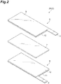
- FIG. 2 is an exploded perspective view showing an electrode group 2 of the secondary battery 1 shown in Figure 1 in an embodiment.
- an electrode group 2A is provided with a positive electrode 6, an electrolyte layer 7 and a negative electrode 8 in this order.
- the positive electrode 6 is provided with a current collector 9 and a positive electrode mixture layer 10 disposed on the current collector 9.
- the current collector 9 of the positive electrode 6 is provided with a positive electrode current collection tab 4.
- the negative electrode 8 is provided with a current collector 11 and a negative electrode mixture layer 12 disposed on the current collector 11.
- the current collector 11 of the negative electrode 8 is provided with a negative electrode current collection tab 5.
- the positive electrode mixture layer 10 and the negative electrode mixture layer 12 are collectively referred to as electrode mixture layer.
- the positive electrode active material and the negative electrode active material described below are collectively referred to as electrode active material.
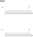
- FIG. 3 (a) is a schematic cross-sectional view showing the first battery member (positive electrode member).
- the first battery member 13 is a positive electrode member provided with a first current collector 9, a positive electrode mixture layer 10 disposed on the first current collector 9, and an electrolyte layer 7 disposed on the positive electrode mixture layer 10 in this order.
- the first current collector 9 may be formed of a metal such as aluminum, titanium and tantalum or an alloy thereof.
- the first current collector 9 is preferably formed of aluminum or an alloy thereof, having light weight with a high weight energy density.
- the positive electrode mixture layer 10 contains a positive electrode active material and an ionic liquid.
- the positive electrode active material may be a lithium transition metal compound such as a lithium transition metal oxide and a lithium transition metal phosphate.
- the lithium transition metal oxide may be, for example, lithium manganate, lithium nickelate and lithium cobaltate.
- the lithium transition metal oxide may be a lithium transition metal oxide comprising a part of transition metals such as Mn, Ni and Co contained in lithium manganate, lithium nickelate, and lithium cobaltate, replaced with one or two or more other transition metals or metal elements such as Mg and Al (typical element).
- the lithium transition metal oxide may be a compound represented by LiM 1 O 2 or LiM 1 O 4 , wherein M 1 comprises at least one transition metal.
- the lithium transition metal oxide may be Li(Co 1/3 Ni 1/3 Mn 1/3 )O 2 , LiNi 1/2 Mn 1/2 O 2 , LiNi 1/2 Mn 3/2 O 4 or the like.
- the lithium transition metal phosphate may be LiFePO 4 , LiMnPO 4 , LiMn x M 3 1-x PO 4 or the like, wherein 0.3 ⁇ x ⁇ 1, and M 3 is at least one element selected from the group consisting of Fe, Ni, Co, Ti, Cu, Zn, Mg and Zr.
- the content of the positive electrode active material may be 70 mass% or more, 80 mass% or more, or 90 mass% or more, based on the total amount of the positive electrode mixture layer.
- the content of the positive electrode active material may be 99 mass% or less based on the total amount of the positive electrode mixture layer.
- the ionic liquid contains the following anionic components and cationic components.
- the ionic liquid in the present specification is a material in a liquid state at -20°C or more.
- the anionic components of the ionic liquid are not particularly limited, and may be halogen anions such as Cl - , Br - and I - , inorganic anions such as BF 4 - and N (SO 2 F) 2 - , or organic anions such as B(C 6 H 5 ) 4 - , CH 3 SO 3 - , CF 3 SO 3 - , N(C 4 F 9 SO 2 ) 2 - , N(SO 2 CF 3 ) 2 - and N(SO 2 CF 2 CF 3 ) 2 - .
- the anionic components of the ionic liquid contain preferably at least one selected from the group consisting of B(C 6 H 5 ) 4 - , CH 3 SO 3 - , N(C 4 F 9 SO 2 ) 2 - , CF 3 SO 3 - , N(SO 2 F) 2 - , N(SO 2 CF 3 ) 2 - and N(SO 2 CF 2 CF 3 ) 2 - to further improve the ionic conductivity at relatively low viscosity, and also from the viewpoint of further improving the charge-discharge characteristic, more preferably at least one selected from the group consisting of N(C 4 F 9 SO 2 ) 2 - , CF 3 SO 3 - , N(SO 2 F) 2 - , N(SO 2 CF 3 ) 2 - and N(SO 2 CF 2 CF 3 ) 2 - , still more preferably N(SO 2 F) 2 - .
- the cationic components of the ionic liquid are not particularly limited and preferably at least one selected from the group consisting of a quaternary onium cation in a chain form, a piperidinium cation, a pyrrolidinium cation, a pyridinium cation, and an imidazolium cation.
- the quaternary onium cation in a chain form is, for example, a compound represented by the following formula (2): wherein R 1 to R 4 each independently represent an alkyl group in a chain form having 1 to 20 carbon atoms, or an alkoxyalkyl group in a chain form represented by R-O-(CH 2 ) n -, wherein R represents a methyl group or an ethyl group and n represents an integer of 1 to 4; X represents a nitrogen atom or a phosphorus atom, and the number of carbon atoms of the alkyl group represented by R 1 to R 4 is preferably 1 to 20, more preferably 1 to 10, still more preferably 1 to 5.
- the piperidinium cation is, for example, a six-membered ring compound containing nitrogen represented by the following formula (3): wherein R 5 and R 6 each independently represent an alkyl group having 1 to 20 carbon atoms, or an alkoxyalkyl group represented by R-O-(CH 2 ) n -, wherein R represents a methyl group or an ethyl group and n represents an integer of 1 to 4; and the number of carbon atoms of the alkyl group represented by R 5 and R 6 is preferably 1 to 20, more preferably 1 to 10, still more preferably 1 to 5.
- the pyrrolidinium cation is, for example, a five-membered ring compound represented by the following formula (4): wherein R 7 and R 8 each independently represent an alkyl group having 1 to 20 carbon atoms, or an alkoxyalkyl group represented by R-O-(CH 2 ) n -, wherein R represents a methyl group or an ethyl group, and n represents an integer of 1 to 4; and the number of carbon atoms of the alkyl group represented by R 7 and R 8 is preferably 1 to 20, more preferably 1 to 10, still more preferably 1 to 5.
- the pyridinium cation is, for example, a compound represented by the following formula (5): wherein R 9 to R 13 each independently represent an alkyl group having 1 to 20 carbon atoms, an alkoxyalkyl group represented by R-O-(CH 2 ) n -, or a hydrogen atom, wherein R represents a methyl group or an ethyl group, and n represents an integer of 1 to 4; and the number of carbon atoms of the alkyl group represented by R 9 to R 13 is preferably 1 to 20, more preferably 1 to 10, still more preferably 1 to 5.
- the imidazolium cation is, for example, a compound represented by the following formula (6): wherein R 14 to R 18 each independently represent an alkyl group having 1 to 20 carbon atoms, an alkoxyalkyl group represented by R-O-(CH 2 ) n -, or a hydrogen atom, wherein R represents a methyl group or an ethyl group, and n represents an integer of 1 to 4; and the number of carbon atoms of the alkyl group represented by R 14 to R 18 is preferably 1 to 20, more preferably 1 to 10, still more preferably 1 to 5.
- the content of the ionic liquid in the positive electrode mixture layer 10 is preferably 3 mass% or more, more preferably 5 mass% or more, still more preferably 10 mass% or more, based on the total amount of the positive electrode mixture layer.
- the content of the ionic liquid in the positive electrode mixture layer 10 is preferably 30 mass% or less, more preferably 25 mass% or less, still more preferably 20 mass% or less, based on the total amount of the positive electrode mixture layer.
- the positive electrode mixture layer 10 may further contain a conductive agent, a binder or the like.
- the conductive agent is not particularly limited, and may be a carbon material such as graphite, acetylene black, carbon black and carbon fiber.
- the conductive agent may be a mixture of a plurality of the carbon materials described above.
- the content of the conductive agent may be 0.1 mass% or more, 1 mass% or more, or 3 mass% or more, and 15 mass% or less, 10 mass% or less, or 8 mass% or less, based on the total amount of the positive electrode mixture layer.
- the binder is not particularly limited, and may be a polymer containing at least one selected from the group consisting of tetrafluoroethylene, vinylidene fluoride, hexafluoropropylene, acrylic acid, maleic acid, ethyl methacrylate, and methyl methacrylate as a monomer unit, a rubber such as styrene-butadiene rubber, isoprene rubber and acrylic rubber, or the like.
- the binder is preferably a copolymer containing tetrafluoroethylene and vinylidene fluoride as structural units.
- An electrolyte salt may be dissolved in the ionic liquid contained in the positive electrode mixture layer 10.
- the electrolyte salt may be at least one selected from the group consisting of a lithium salt, a sodium salt, a calcium salt and a magnesium salt.
- the anion of the electrolyte salt may be a halide ion (I - , Cl - , Br - or the like), SCN - , BF 4 - , BF 3 (CF 3 ) - , BF 3 (C 2 F 5 ) - , PF 6 - , ClO 4 - , SbF 6 - , N(SO 2 F) 2 - , N(SO 2 CF 3 ) 2 - , N(SO 2 C 2 F 5 ) 2 - , BPh 4 - , B(C 2 H 4 O 2 ) 2 - , C(FSO 2 ) 3 - , C(CF 3 SO 2 ) 3 - , CF 3 COO - , CF 3 SO 2 O - , C 6 F 5 SO 2 O - , [B(C 2 O 4 ) 2 ] - or the like.
- the anion is preferably PF 6 - , BF 4 - , N(SO 2 F) 2 - , N(SO 2 CF 3 ) 2 - , [B(C 2 O 4 ) 2 ] - , or ClO 4 - .
- the lithium salt may be at least one selected from the group consisting of LiPF 6 , LiBF 4 , Li[FSI], Li[TFSI], Li[f3C], Li[BOB], LiClO 4 , LiCF 3 BF 3 , LiC 2 F 5 BF 3 , LiC 3 F 7 BF 3 , LiC 4 F 9 BF 3 , Li[C(SO 2 CF 3 ) 3 ], LiCF 3 SO 3 , LiCF 3 COO, and LiRCOO, wherein R is an alkyl group having 1 to 4 carbon atoms, a phenyl group, or a naphthyl group.
- the sodium salt may be at least one selected from the group consisting of NaPF 6 , NaBF 4 , Na[FSI], Na[TFSI], Na[f3C], Na[BOB], NaClO 4 , NaCF 3 BF 3 , NaC 2 F 5 BF 3 , NaC 3 F 7 BF 3 , NaC 4 F 9 BF 3 , Na[C(SO 2 CF 3 ) 3 ], NaCF 3 SO 3 , NaCF 3 COO, and NaRCOO, wherein R is an alkyl group having 1 to 4 carbon atoms, a phenyl group, or a naphthyl group.
- the calcium salt may be at least one selected from the group consisting of Ca(PF 6 ) 2 , Ca(BF 4 ) 2 , Ca[FSI] 2 , Ca[TFSI] 2 , Ca[f3C] 2 , Ca[BOB] 2 , Ca(ClO 4 ) 2 , Ca(CF 3 BF 3 ) 2 , Ca(C 2 F 5 BF 3 ) 2 , Ca(C 3 F 7 BF 3 ) 2 , Ca(C 4 F 9 BF 3 ) 2 , Ca[C(SO 2 CF 3 ) 3 ] 2 , Ca(CF 3 SO 3 ) 2 , Ca(CF 3 COO) 2 , and Ca(RCOO) 2 , wherein R is an alkyl group having 1 to 4 carbon atoms, a phenyl group, or a naphthyl group.
- the magnesium salt may be at least one selected from the group consisting of Mg(PF 6 ) 2 , Mg(BF 4 ) 2 , Mg[FSI] 2 , Mg[TFSI] 2 , Mg[f3C] 2 , Mg[BOB] 2 , Mg(ClO 4 ) 2 , Mg(CF 3 BF 3 ) 2 , Mg(C 2 F 5 BF 3 ) 2 , Mg(C 3 F 7 BF 3 ) 2 , Mg(C 4 F 9 BF 3 ) 2 , Mg[C(SO 2 CF 3 ) 3 ] 2 , Mg(CF 3 SO 3 ) 2 , Mg(CF 3 COO) 2 , and Mg(RCOO) 2 , wherein R is an alkyl group having 1 to 4 carbon atoms, a phenyl group, or a naphthyl group.
- the electrolyte salt is preferably at least one selected from the group consisting of LiPF 6 , LiBF 4 , Li[FSI], Li[TFSI], Li[f3C], Li[BOB], LiClO 4 , LiCF 3 BF 3 , LiC 2 F 5 BF 3 , LiC 3 F 7 BF 3 , LiC 4 F 9 BF 3 , Li[C(SO 2 CF 3 ) 3 ], LiCF 3 SO 3 , LiCF 3 COO, and LiRCOO, wherein R represents an alkyl group having 1 to 4 carbon atoms, a phenyl group, or a naphthyl group; more preferably at least one selected from the group consisting of Li[TFSI], Li[FSI], LiPF 6 , LiBF 4 , Li[BOB] and LiClO 4 , still more preferably at least one selected from the group consisting of Li[TFSI] and Li[FSI].
- the thickness of the positive electrode mixture layer 10 may be 10 ⁇ m or more, 15 ⁇ m or more, or 20 ⁇ m or more.
- the thickness of the positive electrode mixture layer may be 100 ⁇ m or less, 80 ⁇ m or less, or 70 ⁇ m or less.
- the porosity of the positive electrode mixture layer 10 is 10% by volume or less, preferably 5% by volume or less, more preferably 3% by volume or less, still more preferably 1% by volume or less, relative to the volume of the positive electrode mixture layer.
- the porosity of the positive electrode mixture layer is preferably 0.1% by volume or more relative to the volume of the positive electrode mixture layer.
- the porosity is measured by a mercury intrusion method.
- the conditions of mercury porosimetry in the mercury intrusion method are as shown below.
- the electrolyte layer 7 contains, for example, a polymer, oxide particles, an ionic liquid, and at least one electrolyte salt selected from the group consisting of a lithium salt, a sodium salt, a calcium salt and a magnesium salt.
- the polymer has a first structural unit preferably selected from the group consisting of tetrafluoroethylene and vinylidene fluoride.
- the polymer contains preferably one or two or more polymers, and in the structural units constituting the polymers, the first structural unit and a second structural unit selected from the group consisting of hexafluoropropylene, acrylic acid, maleic acid, ethyl methacrylate, and methyl methacrylate may be contained.
- the first structural unit and the second structural unit may be contained in a polymer to constitute a copolymer, or may be contained in separate polymers, respectively, to constitute at least two polymers including a first polymer containing the first structural unit and a second polymer containing the second structural unit.
- the polymer may be polytetrafluoroethylene, polyvinylidene fluoride, a copolymer of vinylidene fluoride and hexafluoropropylene, or the like.
- the content of the polymer is preferably 3 mass% or more based on the total amount of the electrolyte layer.
- the content of the polymer is preferably 50 mass% or less, more preferably 40 mass% or less, based on the total amount of the electrolyte layer.
- the content of the polymer is preferably 3 to 50 mass% or 3 to 40 mass% based on the total amount of the electrolyte layer.
- the oxide particles are, for example, oxide particles of a metal selected from the group consisting of Li, Na, Mg, Al, Si, K, Ca, Sc, Ti, V, Cr, Mn, Fe, Co, Ni, Cu, Zn, Rb, Sr, Y, Nb, Zr, Mo, Ag, Cd, In, Sn, Sb, Cs, Ba, La, Ta, Hf, W, Ir, Tl, Pb and Bi.
- the oxide particles may be silicon oxide, titanium oxide, zinc oxide, aluminum oxide, zirconium oxide, hafnium oxide, niobium oxide, tantalum oxide, magnesium oxide, calcium oxide, strontium oxide, barium oxide, indium oxide, lead oxide or the like.
- the oxide particles may be oxides of rare earth metals.
- the oxide particles may be scandium oxide, yttrium oxide, lanthanum oxide, cerium oxide, praseodymium oxide, neodymium oxide, samarium oxide, europium oxide, gadolinium oxide, terbium oxide, dysprosium oxide, holmium oxide, erbium oxide, thulium oxide, ytterbium oxide, lutetium oxide or the like.
- the oxide particles are preferably iron oxide, zirconium oxide, tin oxide, tungsten oxide, titanium oxide, silicon oxide, zinc oxide, or aluminum oxide.
- the average particle diameter of the oxide particles is preferably 0.005 ⁇ m or more, more preferably 0.01 ⁇ m or more, still more preferably 0.05 ⁇ m or more.
- the average particle diameter of the oxide particles is preferably 5 ⁇ m or less, more preferably 3 ⁇ m or less, still more preferably 1 ⁇ m or less.
- the average particle diameter of the oxide particles is preferably 0.005 to 5 ⁇ m, 0.01 to 3 ⁇ m, or 0.05 to 1 ⁇ m.
- the average particle diameter of the oxide particles is measured by a laser diffraction method, corresponding to the particle diameter at which the cumulative volume reaches 50% in a volume cumulative particle size distribution curve drawn from the small particle diameter side.
- the content of the oxide particles is preferably 5 mass% or more, more preferably 10 mass% or more, still more preferably 15 mass% or more, particularly preferably 20 mass% or more, and preferably 60 mass% or less, more preferably 50 mass% or less, still more preferably 40 mass% or less, based on the total amount of the electrolyte layer.
- the content of the oxide particles is preferably 5 to 60 mass%, 10 to 60 mass%, 15 to 60 mass%, 20 to 60 mass%, 5 to 50 mass%, 10 to 50 mass%, 15 to 50 mass%, 20 to 50 mass%, 5 to 40 mass%, 10 to 40 mass%, 15 to 40 mass%, or 20 to 40 mass%.
- the ionic liquid contained in the electrolyte layer 7 may be the same as the ionic liquid contained in the positive electrode mixture layer described above.
- the content of the ionic liquid in the electrolyte layer 7 is preferably 25 mass% or more, more preferably 30 mass% or more, still more preferably 40 mass% or more, based on the total amount of the electrolyte layer.
- the content of the ionic liquid in the electrolyte layer 7 may be 80 mass% or less based on the total amount of the electrolyte layer, and is preferably 70 mass% or less, more preferably 65 mass% or less, still more preferably 60 mass% or less.
- the electrolyte salt contained in the electrolyte layer 7 may be the same as the electrolyte salt described above, and may be at least one selected from the group consisting of a lithium salt, a sodium salt, a calcium salt and a magnesium salt.
- the electrolyte salt is preferably at least one selected from the group consisting of an imide lithium salt, an imide sodium salt, an imide calcium salt, and an imide magnesium salt.
- the imide lithium salt may be Li[TFSI], Li[FSI] or the like.
- the imide sodium salt may be Na[TFSI], Na [FSI] or the like.
- the imide calcium salt may be Ca[TFSI] 2 , Ca[FSI] 2 or the like.
- the imide magnesium salt may be Mg[TFSI] 2 , Mg[FSI] 2 or the like.
- the concentration of the electrolyte salt per unit volume of the ionic liquid is preferably 0.5 mol/L or more, more preferably 0.7 mol/L or more, still more preferably 0.8 mol/L or more, and preferably 2.0 mol/L or less, more preferably 1.8 mol/L or less, still more preferably 1.5 mol/L or less, from the viewpoint of further improving the charge-discharge characteristic.
- the thickness of the electrolyte layer 7 is preferably 5 ⁇ m or more, more preferably 10 ⁇ m or more, from the viewpoint of enhancing strength to improve safety.
- the thickness of the electrolyte layer 7 is preferably 200 ⁇ m or less, more preferably 150 ⁇ m or less, still more preferably 100 ⁇ m or less, from the viewpoints of further reducing the internal resistance of the secondary battery and further improving the large current characteristic.
- FIG. 3 (b) is a schematic cross-sectional view showing a second battery member (negative electrode member).
- the second battery member is a negative electrode member provided with a second current collector 11, a negative electrode mixture layer 12 disposed on the second current collector 11, and a electrolyte layer 7 disposed on the negative electrode mixture layer 12 in this order. Since the electrolyte layer 7 is the same as the electrolyte layer 7 in the first battery member 13 described above, the explanation thereof is omitted below.
- the second current collector 11 may be a metal such as aluminum, copper, nickel and stainless steel or an alloy thereof.
- the second current collector 11 is preferably aluminum or an alloy thereof, having light weight with a high weight energy density.
- the second current collector 11 is preferably copper, from the viewpoints of easiness in processing into a thin film and cost.
- the negative electrode mixture layer 12 contains a negative electrode active material and an ionic liquid.
- the negative electrode active material may be a carbon material such as graphite and amorphous carbon, a metal material including tin, silicon or the like, lithium titanate (Li 4 Ti 5 O 12 ), metal lithium or the like.
- the content of the negative electrode active material may be 60 mass% or more, 65 mass% or more, or 70 mass% or more, based on the total amount of the negative electrode mixture layer.
- the content of the negative electrode active material may be 99 mass% or less, 95 mass% or less, or 90 mass% or less, based on the total amount of the negative electrode mixture layer.
- the ionic liquid contained in the negative electrode mixture layer 12 may be the same as the ionic liquid contained in the positive electrode mixture layer 10 described above.
- the content of the ionic liquid in the negative electrode mixture layer 12 is preferably 3 mass% or more, more preferably 5 mass% or more, still more preferably 10 mass% or more, based on the total amount of the negative electrode mixture layer.
- the content of the ionic liquid in the negative electrode mixture layer 12 is preferably 30 mass% or less, more preferably 25 mass% or less, still more preferably 20 mass% or less, based on the total amount of the negative electrode mixture layer.
- the negative electrode mixture layer 12 may further contain the conductive agent, the binder or the like usable in the positive electrode mixture layer 10 described above.
- the same electrolyte salt as the electrolyte salt usable in the positive electrode mixture layer 10 may be dissolved.
- the thickness of the negative electrode mixture layer 12 may be 10 ⁇ m or more, 15 ⁇ m or more, or 20 ⁇ m or more.
- the thickness of the negative electrode mixture layer may be 60 ⁇ m or less, 55 ⁇ m or less, or 50 ⁇ m or less.
- the porosity of the negative electrode mixture layer 12 is 10% by volume or less, preferably 5% by volume or less, more preferably 3% by volume or less, still more preferably 1% by volume or less, relative to the volume of the negative electrode mixture layer.
- the porosity of the negative electrode mixture layer 12 is preferably 0.1% by volume or more relative to the volume of the negative electrode mixture layer.
- the production method for the secondary battery 1 comprises a first step of forming a positive electrode mixture layer 10 on a first current collector 9 to obtain a positive electrode 6, a second step of forming a negative electrode mixture layer 12 on a second current collector 11 to obtain a negative electrode 8, and a third step of disposing an electrolyte layer 7 between the positive electrode 6 and the negative electrode 8.
- the positive electrode can be obtained by, for example, dispersing a material for use in the positive electrode mixture layer in a dispersion medium to obtain a slurry-like positive electrode mixture, then applying the positive electrode mixture to the first current collector 9 and drying the positive electrode mixture.
- the dispersion medium is preferably an organic solvent such as n-methyl-2-pyrrolidone.
- the electrolyte salt may be dissolved in the ionic liquid and then dispersed in the dispersion medium together with other materials.
- the method of applying the positive electrode mixture to the first current collector 9 may be, for example, a known method such as coating using an applicator, metal mask printing, electrostatic coating, dip coating, spray coating, roll coating, gravure coating, and screen printing.
- the ratio is not necessarily limited to the range.
- the method of drying the positive electrode mixture applied to the first current collector 9 may be a method using an infrared heater, hot air or the like, and these methods may be used singly or in combination.
- the positive electrode may be placed under vacuum for further drying.
- the positive electrode is subjected to a pressure treatment by flat plate pressing, a calendar rolling or the like, so that the porosity of the positive electrode mixture layer 10 can be controlled to 10% by volume or less.
- the thickness of the positive electrode mixture layer 10 is adjusted, so that the porosity of the positive electrode mixture layer 10 can be controlled to 10% by volume or less.
- the pressed part may be heated.
- the binder in the positive electrode mixture is softened, so that adjustment of the porosity becomes easy.
- the negative electrode is obtained by the same method as in the first step described above.
- the negative electrode is obtained by dispersing the material for use in the negative electrode mixture layer 12 in a dispersion medium to obtain a slurry-like negative electrode mixture, then applying the negative electrode mixture to the second current collector 11 and drying the mixture.
- the ratio is not necessarily limited to the range.
- the porosity of the negative electrode mixture layer 12 may be controlled to 10% by volume or less by the same method in the first step.
- an electrolyte layer 7 is obtained by kneading materials for use in the electrolyte layer 7, then sandwiching the kneaded product between resins of polytetrafluoroethylene or the like in a sheet form, and roll pressing the sandwiched product to obtain an electrolyte layer in a sheet form.
- the positive electrode 6, the electrolyte layer 7, and the negative electrode 8 are stacked, for example, by lamination, so that a secondary battery 1 can be obtained.
- the stacking is performed such that the electrolyte layer 7 is positioned on the positive electrode mixture layer 10 side of the positive electrode 6 and on the negative electrode mixture layer 12 side of the negative electrode 8, or in other words, such that the first current collector 9, the positive electrode mixture layer 10, the electrolyte layer 7, the negative electrode mixture layer 12 and the second current collector 11 are disposed in this order.
- an electrolyte layer 7 is formed on at least one of the surface on the positive electrode mixture layer 10 side of the positive electrode 6 and the surface on the negative electrode mixture layer 12 side of the negative electrode 8.
- the electrolyte layer in a sheet form described above may be stacked on the positive electrode mixture layer 10 side of the positive electrode 6 by lamination.
- a heat treatment or a pressure treatment such as pressing may be performed after formation of the electrolyte layer 7 on the surface on the positive electrode mixture layer 10 side of the positive electrode 6.
- a first battery member 13 (positive electrode member) provided with the first current collector 9, the positive electrode mixture layer 10 and the electrolyte layer 7 in this order is produced.
- the electrolyte layer 7 of the first battery member 13 and the negative electrode mixture layer 12 of the negative electrode 8 are brought into contact to make a laminate, so that a secondary battery 1 is obtained.
- the electrolyte layer in a sheet form described above may be stacked on the negative electrode mixture layer 12 side of the negative electrode 8 by lamination.
- a heat treatment or a pressure treatment such as pressing may be performed after formation of the electrolyte layer 7 on the surface on the negative electrode mixture layer 12 side of the negative electrode 8.
- a second battery member 14 (negative electrode member) provided with the second current collector 9, the negative electrode mixture layer 12 and the electrolyte layer 7 in this order is produced.
- the electrolyte layer 7 of the second battery member 14 and the positive electrode mixture layer 10 of the positive electrode 6 are brought into contact to make a laminate, so that a secondary battery 1 is obtained.
- a secondary battery 1 may be also obtained by forming an electrolyte layer 7 on both of the surface on a positive electrode mixture layer 10 side of a positive electrode 6 and the surface on a negative electrode mixture layer 12 side of a negative electrode 8 by the method described above to obtain a first battery member 13 and a second battery member 14, and then stacking both of the battery members such that the electrolyte layers 7 come into contact with each other.
- FIG. 4 is an exploded perspective view showing an electrode group of a secondary battery in the second embodiment.
- the same symbols as in the first embodiment are used and redundant explanation is omitted.
- the point of difference in the secondary battery in the second embodiment from the secondary battery in the first embodiment is that an electrode group 2B is further provided with a bipolar electrode 15.
- the electrode group 2B is further provided with a positive electrode 6, a first electrolyte layer 7, a bipolar electrode 15, a second electrolyte layer 7 and a negative electrode 8 in this order.
- the bipolar electrode 15 is provided with a third current collector 16, a positive electrode mixture layer 10 disposed on a surface on a negative electrode 8 side of the third current collector 16, and a negative electrode mixture layer 12 disposed on a surface on a positive electrode 6 side of the third current collector 16.
- a third battery member (bipolar electrode member) provided with a first electrolyte layer 7, a bipolar electrode 15 and a second electrolyte layer 7 in this order is included.
- Figure 5 is a schematic cross-sectional view showing the third battery member (bipolar electrode member).
- the third battery member 17 is provided with a third current collector 16, a positive electrode mixture layer 10 disposed on one surface of the third current collector 16, a second electrolyte layer 7 disposed opposed to the third current collector 16 on the positive electrode mixture layer 10, a negative electrode mixture layer 12 disposed on another surface of the third current collector 16, and a first electrolyte layer 7 disposed opposite to the third current collector 16 on the negative electrode mixture layer 12.
- the third current collector 16 is formed of, for example, a single metal such as aluminum, stainless steel and titanium, or a clad material produced by roll bonding aluminum and copper, or stainless steel and copper.
- the first electrolyte layer 7 and the second electrolyte layer 7 may be the same or different from each other and are preferably the same as each other.
- Lithium bis(fluorosulfonyl)imide (Li[FSI]) dried under dry argon atmosphere for use as electrolyte salt was dissolved in N-methyl -N-propylpyrrolidinium bis(fluorosulfonyl)imide (Py13FSI) as an ionic liquid at a concentration of 1 mol/L (hereinafter, a composition of the ionic liquid dissolving an electrolyte salt is described as "concentration of lithium salt/type of lithium salt/type of ionic liquid" in some cases).
- An ionic liquid dissolving an electrolyte salt as described above and SiO 2 particles having an average particle diameter of 0.1 ⁇ m were mixed at a volume ratio (ionic liquid dissolving electrolyte salt/SiO 2 ) of 80/20, while stirring in methanol for 30 minutes or more.
- the mixture was then distilled at 60°C by using an evaporator.
- the composition obtained by distillation and polytetrafluoroethylene were mixed at a mass ratio (composition/polytetrafluoroethylene) of 95/5 and kneaded with a mortar for 30 minutes or more to obtain an electrolyte composition.
- the resulting electrolyte composition was sandwiched between two sheets of polytetrafluoroethylene (PTFE) and subjected to pressing by a roll pressing machine to obtain an electrolyte sheet having a thickness of 200 ⁇ m.
- the electrolyte sheet was punched out to a diameter of 16 mm to make an electrolyte layer.
- the content of the polytetrafluoroethylene, the content of SiO 2 particles and the content of the ionic liquid and the lithium salt in total were 13 mass%, 25 mass% and 62 mass%, respectively, based on the total amount of the electrolyte layer.
- a positive electrode mixture slurry was prepared by mixing 70 parts by mass of a layered lithium-nickel-manganese-cobalt composite oxide (positive electrode active material), 7 parts by mass of acetylene black (conductive agent, average particle diameter of 48 nm, product name: HS-100, manufactured by Denka Co., Ltd.), 9 parts by mass of a copolymer solution (solid content: 12 mass%) of vinylidene fluoride and hexafluoropropylene, and 14 parts by mass of an ionic liquid dissolving an electrolyte salt (1M/Li[FSI]/Py13FSI).
- the positive electrode mixture slurry was applied to a current collector (aluminum foil having a thickness of 20 ⁇ m) at a coating weight 160 g/m 2 and dried at 80°C.
- a current collector aluminum foil having a thickness of 20 ⁇ m
- the thickness of the positive electrode mixture layer was adjusted to form a positive electrode mixture layer having a mixture density of 2.82 g/cm 3 (porosity: 0.22%).
- the positive electrode mixture layer was punched out to a diameter of 15 mm to make a positive electrode.
- a negative electrode mixture slurry was prepared by mixing 74 parts by mass of graphite (negative electrode active material, manufactured by Hitachi Chemical Co., Ltd.), 2 parts by mass of acetylene black (conductive agent, average particle diameter of 48 nm, product name: HS-100, manufactured by Denka Co., Ltd.), 10 parts by mass of a copolymer solution (solid content: 12 mass%) of vinylidene fluoride and hexafluoropropylene, and 14 parts by mass of an ionic liquid dissolving an electrolyte salt (1M/Li[FSI]/Py13FSI).
- the negative electrode mixture slurry was applied to a current collector (copper foil having a thickness of 10 ⁇ m) at a coating weight of 90 g/m 2 and dried at 80°C.
- a current collector copper foil having a thickness of 10 ⁇ m
- the thickness of the negative electrode mixture layer was adjusted to form a negative electrode mixture layer having a mixture density of 2.97 g/cm 3 (porosity: 0.64%).
- the negative electrode mixture layer was punched out to a diameter of 16 mm to make a negative electrode.
- a coin battery was prepared by using a positive electrode, an electrolyte layer, and a negative electrode.
- the positive electrode, the electrolyte layer, and the negative electrode were stacked in this order, placed in a CR2032-type coin cell container, and then hermetically enclosed therein by caulking the top of the cell container through an insulating gasket.
- a coin battery was prepared in the same manner as in Example 1, except that by pressing with a roll pressing machine capable of gap adjustment, the thickness of the positive electrode mixture layer was adjusted to control the mixture density of the positive electrode mixture layer to 2.80 g/cm 3 (porosity: 0.93%).
- a coin battery was prepared in the same manner as in Example 1, except that by pressing with a roll pressing machine capable of gap adjustment, the thickness of the positive electrode mixture layer was adjusted to control the mixture density of the positive electrode mixture layer to 2.75 g/cm 3 (porosity: 2.70%).
- a coin battery was prepared in the same manner as in Example 1, except that by pressing with a roll pressing machine capable of gap adjustment, the thickness of the positive electrode mixture layer was adjusted to control the mixture density of the positive electrode mixture layer to 2.70 g/cm 3 (porosity: 4.47%).
- a coin battery was prepared in the same manner as in Example 1, except that by pressing with a roll pressing machine capable of gap adjustment, the thickness of the positive electrode mixture layer was adjusted to control the mixture density of the positive electrode mixture layer to 2.65 g/cm 3 (porosity: 6.24%).
- a coin battery was prepared in the same manner as in Example 1, except that by pressing with a roll pressing machine capable of gap adjustment, the thickness of the positive electrode mixture layer was adjusted to control the mixture density of the positive electrode mixture layer to 2.55 g/cm 3 (porosity: 9.78%).
- a coin battery was prepared in the same manner as in Example 1, except that by pressing with a roll pressing machine capable of gap adjustment, the thickness of the negative electrode mixture layer was adjusted to control the mixture density of the negative electrode mixture layer to 1.94 g/cm 3 (porosity: 2.15%).
- a coin battery was prepared in the same manner as in Example 1, except that by pressing with a roll pressing machine capable of gap adjustment, the thickness of the negative electrode mixture layer was adjusted to control the mixture density of the negative electrode mixture layer to 1.90 g/cm 3 (porosity: 4.17%).
- a coin battery was prepared in the same manner as in Example 1, except that by pressing with a roll pressing machine capable of gap adjustment, the thickness of the negative electrode mixture layer was adjusted to control the mixture density of the negative electrode mixture layer to 1.80 g/cm 3 (porosity: 9.22%).
- a coin battery was prepared in the same manner as in Example 1, except that 1-ethyl-3-methyl-imidazolium bis(fluorosulfonyl)imide (EMIFSI) was used as the ionic liquid in preparation of the electrolyte layer in Example 1.
- EMIFSI 1-ethyl-3-methyl-imidazolium bis(fluorosulfonyl)imide
- a coin battery was prepared in the same manner as in Example 1, except that SiO 2 particles (average particle diameter: 1.0 ⁇ m) were used as the oxide particles in preparation of the electrolyte layer in Example 1.
- a coin battery was prepared in the same manner as in Example 1, except that SiO 2 particles (average particle diameter: 3.0 ⁇ m) were used as the oxide particles in preparation of the electrolyte layer in Example 1.
- a coin battery was prepared in the same manner as in Example 1, except that CeO 2 particles (average particle diameter: 0.02 ⁇ m) were used as the oxide particles in preparation of the electrolyte layer in Example 1.
- a coin battery was prepared in the same manner as in Example 1, except that a copolymer of vinylidene fluoride and hexafluoropropylene was used as the polymer in preparation of the electrolyte layer in Example 1.
- a coin battery was prepared in the same manner as in Example 14, except that CeO 2 particles (average particle diameter: 0.02 ⁇ m) were used as the oxide particles in preparation of the electrolyte layer in Example 14.
- a coin battery was prepared in the same manner as in Example 1, except that polyvinylidene fluoride was used as the polymer in preparation of the electrolyte layer in Example 1.
- a coin battery was prepared in the same manner as in Example 1, except that by pressing with a roll pressing machine capable of gap adjustment, the thickness of the positive electrode mixture layer was adjusted to control the mixture density of the positive electrode mixture layer to 2.40 g/cm 3 (porosity: 15.08%).
- a coin battery was prepared in the same manner as in Example 1, except that by pressing with a roll pressing machine capable of gap adjustment, the thickness of the negative electrode mixture layer was adjusted to control the mixture density of the negative electrode mixture layer to 1.65 g/cm 3 (porosity: 16.78%).
- the discharge capacity at 25°C of the coin batteries obtained in Examples 1 to 13 was measured by using a charge-discharge unit (manufactured by Toyo System Co., Ltd.) under the following charge-discharge conditions.
- Discharge characteristic % discharge capacity determined in 2 / discharge capacity determined in 1 ⁇ 100 [Table 1] Porosity of positive electrode mixture layer (% by volume) Porosity of negative electrode mixture layer (% by volume) Discharge characteristic (%) Example 1 0.22 0.64 99 Example 2 0.93 0.64 97 Example 3 2.7 0.64 92 Example 4 4.47 0.64 90 Example 5 6.24 0.64 87 Example 6 9.78 0.64 83 Example 7 0.22 2.15 98 Example 8 0.22 4.17 90 Example 9 0.22 9.22 84 Example 10 0.22 0.64 97 Example 11 0.22 0.64 98 Example 12 0.22 0.64 95 Example 13 0.22 0.64 100 Example 14 0.22 0.64 100 Example 15 0.22 0.64 100 Example 16 0.22 0.64 92 Reference Example 1 15.08 0.64 65 Reference Example 2 0.22 16.78 58
Landscapes
- Chemical & Material Sciences (AREA)
- Chemical Kinetics & Catalysis (AREA)
- Electrochemistry (AREA)
- General Chemical & Material Sciences (AREA)
- Engineering & Computer Science (AREA)
- Manufacturing & Machinery (AREA)
- Inorganic Chemistry (AREA)
- Physics & Mathematics (AREA)
- Condensed Matter Physics & Semiconductors (AREA)
- General Physics & Mathematics (AREA)
- Materials Engineering (AREA)
- Composite Materials (AREA)
- Dispersion Chemistry (AREA)
- Secondary Cells (AREA)
- Battery Electrode And Active Subsutance (AREA)
Abstract
Description
- The present invention relates to a battery member for secondary battery, a secondary battery, and production methods therefor.
- In recent years, portable electronic devices and electric vehicles are in widespread use, and high-performance secondary batteries are therefore required. In particular, lithium secondary batteries are used as a power source of portable electronic devices and electric vehicles due to having a high energy density.
- For example, in a 18650-type lithium secondary battery, a rolled electrode body is accommodated inside a cylindrical battery can. The rolled electrode body includes a positive electrode, a negative electrode and a microporous separator sandwiched therebetween, which are wound in a spiral form. Since the separator in the rolled electrode body is impregnated with a flammable electrolyte solution, for example, when the temperature of the battery rises rapidly in abnormal state, the lithium secondary battery may possibly burst due to vaporization of the electrolyte solution to increase the internal pressure, and the electrolyte solution may possibly ignite. Preventing a lithium secondary battery from bursting and igniting is important in designing the lithium secondary battery. In other words, in further planning high energy densification and increase in size of a lithium secondary battery from this time, further improvement in safety is required.
- As a drastic solution for improving the safety of a lithium secondary battery, an all-solid-state battery is in under development. In an all-solid-state battery, instead of an electrolyte solution, a layer of a solid electrolyte such as a polymer electrolyte or an inorganic solid electrolyte is provided on an electrode mixture layer (for example, Patent Literature 1).
- Patent Literature 1: Japanese Unexamined Patent Publication No.
2006-294326 - However, in the case of using a solid electrolyte, it is more difficult to satisfactorily form an interface with an electrode mixture layer as compared to the case of using an electrolyte solution. The contact area between the electrode mixture layer and the solid electrolyte is therefore reduced, and, for example, the discharge characteristic of a secondary battery may be remarkably reduced.
- An object in an aspect of the present invention is, therefore, to provide a battery member capable of improving the discharge characteristic of a secondary battery, and a production method therefor. An object in another aspect of the present invention is to provide a secondary battery excellent in discharge characteristic and a production method therefor.
- A first aspect of the present invention relates to a battery member for a secondary battery comprising a current collector, an electrode mixture layer disposed on the current collector, and an electrolyte layer disposed on the electrode mixture layer in this order, wherein the electrode mixture layer comprises an electrode active material and an ionic liquid, and the porosity of the electrode mixture layer is 10% by volume or less relative to the volume of the electrode mixture layer.
- The electrode mixture layer may be a positive electrode mixture layer or a negative electrode mixture layer. The electrode active material may be a positive electrode active material or a negative electrode active material.
- A second aspect of the present invention relates to a secondary battery comprising: a positive electrode comprising a first current collector, and a positive electrode mixture layer disposed on the first current collector and comprising a positive electrode active material and an ionic liquid; a negative electrode comprising a second current collector, and a negative electrode mixture layer disposed on the second current collector and comprising a negative electrode active material and an ionic liquid; and an electrolyte layer disposed between the positive electrode and the negative electrode; wherein the porosity of the positive electrode mixture layer is 10% by volume or less relative to the volume of the positive electrode mixture layer, and the porosity of the negative electrode mixture layer is 10% by volume or less relative to the volume of the positive electrode mixture layer or the negative electrode mixture layer.
- In the first and the second aspects, preferably the ionic liquid comprises at least one selected from the group consisting of N(C4F9SO2)2 -, CF3SO3 -, N(SO2F)2 -, N(SO2CF3)2 - and N(SO2CF2CF3)2 -, as an anionic component.
- In the first and the second aspects, preferably the ionic liquid comprises at least one selected from the group consisting of a quaternary onium cation in a chain form, a piperidinium cation, a pyrrolidinium cation, a pyridinium cation, and an imidazolium cation, as a cationic component.
- In the first and the second aspects, preferably the electrolyte layer comprises a polymer, oxide particles, an ionic liquid, and at least one electrolyte salt selected from the group consisting of a lithium salt, a sodium salt, a calcium salt and a magnesium salt.
- In the first and the second aspects, preferably the electrolyte salt is at least one selected from the group consisting of an imide lithium salt, an imide sodium salt, an imide calcium salt and an imide magnesium salt.
- In the first and the second aspects, preferably the content of the oxide particles is 5 to 40 mass% based on the total amount of the electrolyte layer.
- In the first and the second aspects, the average particle diameter of the oxide particles is preferably 0.005 to 5 µm.
- In the first and the second aspects, the content of the polymer is preferably 3 to 40 mass% based on the total amount of the electrolyte layer.
- In the first and the second aspects, preferably the polymer comprises a first structural unit selected from the group consisting of tetrafluoroethylene and vinylidene fluoride.
- In the first and the second aspects, the polymer comprises preferably one or two or more polymers, and the first structural unit and a second structural unit selected from the group consisting of hexafluoropropylene, acrylic acid, maleic acid, ethyl methacrylate, and methyl methacrylate are included in structural units constituting the one or two or more polymers.
- A third aspect of the present invention relates to a production method for battery members for secondary batteries comprising: forming an electrode mixture layer containing an electrode active material and an ionic liquid on a current collector to obtain an electrode, and disposing an electrolyte layer opposite to the current collector of the electrode, wherein the porosity of the electrode mixture layer is controlled to 10% by volume or less relative to the volume of the electrode mixture layer.
- A fourth aspect of the present invention relates to a production method for secondary batteries comprising: forming a positive electrode mixture layer comprising a positive electrode active material and an ionic liquid on a first current collector to obtain a positive electrode, forming a negative electrode mixture layer containing a negative electrode active material and an ionic liquid on a second current collector to obtain a negative electrode, and disposing an electrolyte layer between the positive electrode and the negative electrode in such a way that the electrolyte layer positioned on the positive electrode mixture layer side of the positive electrode and on the negative electrode mixture layer side of the negative electrode, wherein the porosity of the positive electrode mixture layer is controlled to 10% by volume or less relative to the volume of the positive electrode mixture layer, and the porosity of the negative electrode mixture layer is controlled to 10% by volume or less relative to the volume of the negative electrode mixture layer.
- According to an aspect of the present invention, a battery member capable of improving the discharge characteristic of a secondary battery and a production method therefor can be provided. Further, according to another aspect of the present invention, a secondary battery excellent in discharge characteristic and a production method therefor can be provided.
-
-
Figure 1 is a perspective view showing a secondary battery in a first embodiment. -
Figure 2 is an exploded perspective view showing an electrode group of the secondary battery shown inFigure 1 . -
Figure 3 (a) is a schematic cross-sectional view showing a battery member (positive electrode member) for a secondary battery in an embodiment, andFigure 3 (b) is a schematic cross-sectional view showing a battery member (negative electrode member) for a secondary battery in another embodiment. -
Figure 4 is an exploded perspective view showing an electrode group of a secondary battery in a second embodiment. -
Figure 5 is a schematic cross-sectional view showing a battery member (bipolar electrode member) for a secondary battery in another embodiment. - With appropriate reference to drawings, embodiments of the present invention will be described in detail below. The present invention, however, is not limited to the following embodiments. In the following embodiments, the constitutional elements (including steps or the like) thereof are not essential except for particularly specified cases. The sizes of the constitutional elements shown in each of the drawings are conceptual and relative relations of sizes among the constitutional elements are not limited to those shown in each of the drawings.
- Numerical values and numerical ranges in the present specification do not limit the present invention. A numerical range represented by using "to" in the present specification represents a range including the numerical values described at the front or rear of "to" as the minimum value or the maximum value. In the numerical range stepwisely described in the present specification, an upper limit or a lower limit of the numerical range in a step may be replaced with an upper limit or a lower limit of the numerical range in another step. Also, an upper limit or a lower limit in the numerical range described in the present specification may be replaced with the values shown in Examples.
-
Figure 1 is a perspective view showing a secondary battery in a first embodiment. As shown inFigure 1 , asecondary battery 1 is provided with anelectrode group 2 comprising a positive electrode, a negative electrode and an electrolyte layer, and a bag-shaped batteryouter package 3 accommodating theelectrode group 2. The positive electrode and the negative electrode are provided with a positive electrodecurrent collection tab 4 and a negative electrodecurrent collection tab 5, respectively. The positive electrodecurrent collection tab 4 and the negative electrodecurrent collection tab 5 protrude from the inside to the outside of the batteryouter package 3, such that the positive electrode and the negative electrode can be electrically connected to the outside of thesecondary battery 1, respectively. - The battery
outer package 3 may be formed of, for example, a laminate film. The laminate film may be, for example, a laminate film of a resin film such as polyethylene terephthalate (PET) film, a foil of metal such as aluminum, copper and stainless steel, and a sealant layer of polypropylene or the like, which are stacked in this order. -
Figure 2 is an exploded perspective view showing anelectrode group 2 of thesecondary battery 1 shown inFigure 1 in an embodiment. As shown inFigure 2 , anelectrode group 2A is provided with apositive electrode 6, anelectrolyte layer 7 and anegative electrode 8 in this order. Thepositive electrode 6 is provided with acurrent collector 9 and a positiveelectrode mixture layer 10 disposed on thecurrent collector 9. Thecurrent collector 9 of thepositive electrode 6 is provided with a positive electrodecurrent collection tab 4. Thenegative electrode 8 is provided with acurrent collector 11 and a negativeelectrode mixture layer 12 disposed on thecurrent collector 11. Thecurrent collector 11 of thenegative electrode 8 is provided with a negative electrodecurrent collection tab 5. Incidentally, the positiveelectrode mixture layer 10 and the negativeelectrode mixture layer 12 are collectively referred to as electrode mixture layer. Similarly, the positive electrode active material and the negative electrode active material described below are collectively referred to as electrode active material. - In an embodiment, it can be regarded that in an
electrode group 2A, a first battery member (positive electrode member) provided with a firstcurrent collector 9, a positiveelectrode mixture layer 10 and anelectrolyte layer 7 in this order is included.Figure 3 (a) is a schematic cross-sectional view showing the first battery member (positive electrode member). As shown inFigure 3 (a) , thefirst battery member 13 is a positive electrode member provided with a firstcurrent collector 9, a positiveelectrode mixture layer 10 disposed on the firstcurrent collector 9, and anelectrolyte layer 7 disposed on the positiveelectrode mixture layer 10 in this order. - The first
current collector 9 may be formed of a metal such as aluminum, titanium and tantalum or an alloy thereof. The firstcurrent collector 9 is preferably formed of aluminum or an alloy thereof, having light weight with a high weight energy density. - In an embodiment, the positive
electrode mixture layer 10 contains a positive electrode active material and an ionic liquid. The positive electrode active material may be a lithium transition metal compound such as a lithium transition metal oxide and a lithium transition metal phosphate. - The lithium transition metal oxide may be, for example, lithium manganate, lithium nickelate and lithium cobaltate. The lithium transition metal oxide may be a lithium transition metal oxide comprising a part of transition metals such as Mn, Ni and Co contained in lithium manganate, lithium nickelate, and lithium cobaltate, replaced with one or two or more other transition metals or metal elements such as Mg and Al (typical element). In other words, the lithium transition metal oxide may be a compound represented by LiM1O2 or LiM1O4, wherein M1 comprises at least one transition metal. Specifically, the lithium transition metal oxide may be Li(Co1/3Ni1/3Mn1/3)O2, LiNi1/2Mn1/2O2, LiNi1/2Mn3/2O4 or the like.
- The lithium transition metal oxide is preferably a compound represented by the following formula (1), from the viewpoint of further improving the energy density:
LiaNibCocM2 dO2+e (1)
wherein M2 is at least one selected from the group consisting of Al, Mn, Mg and Ca, and a, b, c, d and e are numbers satisfying 0.2≤ a≤1.2, 0.5≤b≤0.9, 0.1≤c≤0.4, 0≤d≤0.2, -0.2≤e≤0.2 and b+c+d=1. - The lithium transition metal phosphate may be LiFePO4, LiMnPO4, LiMnxM3 1-xPO4 or the like, wherein 0.3≤x≤1, and M3 is at least one element selected from the group consisting of Fe, Ni, Co, Ti, Cu, Zn, Mg and Zr.
- The content of the positive electrode active material may be 70 mass% or more, 80 mass% or more, or 90 mass% or more, based on the total amount of the positive electrode mixture layer. The content of the positive electrode active material may be 99 mass% or less based on the total amount of the positive electrode mixture layer.
- The ionic liquid contains the following anionic components and cationic components. Incidentally, the ionic liquid in the present specification is a material in a liquid state at -20°C or more.
- The anionic components of the ionic liquid are not particularly limited, and may be halogen anions such as Cl-, Br- and I-, inorganic anions such as BF4 - and N (SO2F)2 -, or organic anions such as B(C6H5)4 -, CH3SO3 -, CF3SO3 -, N(C4F9SO2)2 -, N(SO2CF3)2 - and N(SO2CF2CF3)2 -. The anionic components of the ionic liquid contain preferably at least one selected from the group consisting of B(C6H5)4 -, CH3SO3 -, N(C4F9SO2)2 -, CF3SO3 -, N(SO2F)2 -, N(SO2CF3)2 - and N(SO2CF2CF3)2 - to further improve the ionic conductivity at relatively low viscosity, and also from the viewpoint of further improving the charge-discharge characteristic, more preferably at least one selected from the group consisting of N(C4F9SO2)2 -, CF3SO3 -, N(SO2F)2 -, N(SO2CF3)2 - and N(SO2CF2CF3)2 -, still more preferably N(SO2F)2 -.
- The cationic components of the ionic liquid are not particularly limited and preferably at least one selected from the group consisting of a quaternary onium cation in a chain form, a piperidinium cation, a pyrrolidinium cation, a pyridinium cation, and an imidazolium cation.
- The quaternary onium cation in a chain form is, for example, a compound represented by the following formula (2):

- The piperidinium cation is, for example, a six-membered ring compound containing nitrogen represented by the following formula (3):

- The pyrrolidinium cation is, for example, a five-membered ring compound represented by the following formula (4):

- The pyridinium cation is, for example, a compound represented by the following formula (5):

- The imidazolium cation is, for example, a compound represented by the following formula (6):

- The content of the ionic liquid in the positive
electrode mixture layer 10 is preferably 3 mass% or more, more preferably 5 mass% or more, still more preferably 10 mass% or more, based on the total amount of the positive electrode mixture layer. The content of the ionic liquid in the positiveelectrode mixture layer 10 is preferably 30 mass% or less, more preferably 25 mass% or less, still more preferably 20 mass% or less, based on the total amount of the positive electrode mixture layer. - The positive
electrode mixture layer 10 may further contain a conductive agent, a binder or the like. - The conductive agent is not particularly limited, and may be a carbon material such as graphite, acetylene black, carbon black and carbon fiber. The conductive agent may be a mixture of a plurality of the carbon materials described above.
- The content of the conductive agent may be 0.1 mass% or more, 1 mass% or more, or 3 mass% or more, and 15 mass% or less, 10 mass% or less, or 8 mass% or less, based on the total amount of the positive electrode mixture layer.
- The binder is not particularly limited, and may be a polymer containing at least one selected from the group consisting of tetrafluoroethylene, vinylidene fluoride, hexafluoropropylene, acrylic acid, maleic acid, ethyl methacrylate, and methyl methacrylate as a monomer unit, a rubber such as styrene-butadiene rubber, isoprene rubber and acrylic rubber, or the like. The binder is preferably a copolymer containing tetrafluoroethylene and vinylidene fluoride as structural units.
- An electrolyte salt may be dissolved in the ionic liquid contained in the positive
electrode mixture layer 10. The electrolyte salt may be at least one selected from the group consisting of a lithium salt, a sodium salt, a calcium salt and a magnesium salt. - The anion of the electrolyte salt may be a halide ion (I-, Cl-, Br- or the like), SCN-, BF4 -, BF3(CF3)-, BF3(C2F5)-, PF6 -, ClO4 -, SbF6 -, N(SO2F)2 -, N(SO2CF3)2 -, N(SO2C2F5)2 -, BPh4 -, B(C2H4O2)2 -, C(FSO2)3 -, C(CF3SO2)3 -, CF3COO-, CF3SO2O-, C6F5SO2O-, [B(C2O4)2]- or the like. The anion is preferably PF6 -, BF4 -, N(SO2F)2 -, N(SO2CF3)2 -, [B(C2O4)2]-, or ClO4 -.
- Incidentally, the following abbreviations may be used below:
- [FSI]-: N(SO2F)2 -, bis(fluorosulfonyl)imide anion
- [TFSI]-: N(SO2CF3)2 -, bis(trifluoromethanesulfonyl)imide anion
- [BOB]-: [B(C2O4)2]-, bis(oxalate)borate anion
- [f3C]-: C(FSO2)3 -, tris(fluorosulfonyl)carbanion
- The lithium salt may be at least one selected from the group consisting of LiPF6, LiBF4, Li[FSI], Li[TFSI], Li[f3C], Li[BOB], LiClO4, LiCF3BF3, LiC2F5BF3, LiC3F7BF3, LiC4F9BF3, Li[C(SO2CF3)3], LiCF3SO3, LiCF3COO, and LiRCOO, wherein R is an alkyl group having 1 to 4 carbon atoms, a phenyl group, or a naphthyl group.
- The sodium salt may be at least one selected from the group consisting of NaPF6, NaBF4, Na[FSI], Na[TFSI], Na[f3C], Na[BOB], NaClO4, NaCF3BF3, NaC2F5BF3, NaC3F7BF3, NaC4F9BF3, Na[C(SO2CF3)3], NaCF3SO3, NaCF3COO, and NaRCOO, wherein R is an alkyl group having 1 to 4 carbon atoms, a phenyl group, or a naphthyl group.
- The calcium salt may be at least one selected from the group consisting of Ca(PF6)2, Ca(BF4)2, Ca[FSI]2, Ca[TFSI]2, Ca[f3C]2, Ca[BOB]2, Ca(ClO4)2, Ca(CF3BF3)2, Ca(C2F5BF3)2, Ca(C3F7BF3)2, Ca(C4F9BF3)2, Ca[C(SO2CF3)3]2, Ca(CF3SO3)2, Ca(CF3COO)2, and Ca(RCOO)2, wherein R is an alkyl group having 1 to 4 carbon atoms, a phenyl group, or a naphthyl group.
- The magnesium salt may be at least one selected from the group consisting of Mg(PF6)2, Mg(BF4)2, Mg[FSI]2, Mg[TFSI]2, Mg[f3C]2, Mg[BOB]2, Mg(ClO4)2, Mg(CF3BF3)2, Mg(C2F5BF3)2, Mg(C3F7BF3)2, Mg(C4F9BF3)2, Mg[C(SO2CF3)3]2, Mg(CF3SO3)2, Mg(CF3COO)2, and Mg(RCOO)2, wherein R is an alkyl group having 1 to 4 carbon atoms, a phenyl group, or a naphthyl group.
- Among these, from the viewpoints of dissociation properties and electrochemical stability, the electrolyte salt is preferably at least one selected from the group consisting of LiPF6, LiBF4, Li[FSI], Li[TFSI], Li[f3C], Li[BOB], LiClO4, LiCF3BF3, LiC2F5BF3, LiC3F7BF3, LiC4F9BF3, Li[C(SO2CF3)3], LiCF3SO3, LiCF3COO, and LiRCOO, wherein R represents an alkyl group having 1 to 4 carbon atoms, a phenyl group, or a naphthyl group; more preferably at least one selected from the group consisting of Li[TFSI], Li[FSI], LiPF6, LiBF4, Li[BOB] and LiClO4, still more preferably at least one selected from the group consisting of Li[TFSI] and Li[FSI].
- The thickness of the positive
electrode mixture layer 10 may be 10 µm or more, 15 µm or more, or 20 µm or more. The thickness of the positive electrode mixture layer may be 100 µm or less, 80 µm or less, or 70 µm or less. - The porosity of the positive
electrode mixture layer 10 is 10% by volume or less, preferably 5% by volume or less, more preferably 3% by volume or less, still more preferably 1% by volume or less, relative to the volume of the positive electrode mixture layer. The porosity of the positive electrode mixture layer is preferably 0.1% by volume or more relative to the volume of the positive electrode mixture layer. With a volume of pores in the positive electrode mixture layer in the range, the interface between the ionic liquid and other compounds is formed in good condition to reduce the internal resistance of the battery, so that excellent discharge characteristic can be obtained when the positive electrode member is applied to a secondary battery. - The porosity is measured by a mercury intrusion method. The conditions of mercury porosimetry in the mercury intrusion method are as shown below.
- Apparatus: AutoPore IV 9500, manufactured by Shimadzu Corporation
Surface tension of mercury: 475 dynes/cm
Density of mercury: 13.534 g/mL - The
electrolyte layer 7 contains, for example, a polymer, oxide particles, an ionic liquid, and at least one electrolyte salt selected from the group consisting of a lithium salt, a sodium salt, a calcium salt and a magnesium salt. - The polymer has a first structural unit preferably selected from the group consisting of tetrafluoroethylene and vinylidene fluoride.
- The polymer contains preferably one or two or more polymers, and in the structural units constituting the polymers, the first structural unit and a second structural unit selected from the group consisting of hexafluoropropylene, acrylic acid, maleic acid, ethyl methacrylate, and methyl methacrylate may be contained. In other words, the first structural unit and the second structural unit may be contained in a polymer to constitute a copolymer, or may be contained in separate polymers, respectively, to constitute at least two polymers including a first polymer containing the first structural unit and a second polymer containing the second structural unit.
- Specifically, the polymer may be polytetrafluoroethylene, polyvinylidene fluoride, a copolymer of vinylidene fluoride and hexafluoropropylene, or the like.
- The content of the polymer is preferably 3 mass% or more based on the total amount of the electrolyte layer. The content of the polymer is preferably 50 mass% or less, more preferably 40 mass% or less, based on the total amount of the electrolyte layer. The content of the polymer is preferably 3 to 50 mass% or 3 to 40 mass% based on the total amount of the electrolyte layer.
- The oxide particles are, for example, oxide particles of a metal selected from the group consisting of Li, Na, Mg, Al, Si, K, Ca, Sc, Ti, V, Cr, Mn, Fe, Co, Ni, Cu, Zn, Rb, Sr, Y, Nb, Zr, Mo, Ag, Cd, In, Sn, Sb, Cs, Ba, La, Ta, Hf, W, Ir, Tl, Pb and Bi. Specifically, the oxide particles may be silicon oxide, titanium oxide, zinc oxide, aluminum oxide, zirconium oxide, hafnium oxide, niobium oxide, tantalum oxide, magnesium oxide, calcium oxide, strontium oxide, barium oxide, indium oxide, lead oxide or the like.
- The oxide particles may be oxides of rare earth metals. Specifically, the oxide particles may be scandium oxide, yttrium oxide, lanthanum oxide, cerium oxide, praseodymium oxide, neodymium oxide, samarium oxide, europium oxide, gadolinium oxide, terbium oxide, dysprosium oxide, holmium oxide, erbium oxide, thulium oxide, ytterbium oxide, lutetium oxide or the like. From the viewpoint of further improving the ion conductivity, the oxide particles are preferably iron oxide, zirconium oxide, tin oxide, tungsten oxide, titanium oxide, silicon oxide, zinc oxide, or aluminum oxide.
- The average particle diameter of the oxide particles is preferably 0.005 µm or more, more preferably 0.01 µm or more, still more preferably 0.05 µm or more. The average particle diameter of the oxide particles is preferably 5 µm or less, more preferably 3 µm or less, still more preferably 1 µm or less. The average particle diameter of the oxide particles is preferably 0.005 to 5 µm, 0.01 to 3 µm, or 0.05 to 1 µm. The average particle diameter of the oxide particles is measured by a laser diffraction method, corresponding to the particle diameter at which the cumulative volume reaches 50% in a volume cumulative particle size distribution curve drawn from the small particle diameter side.
- The content of the oxide particles is preferably 5 mass% or more, more preferably 10 mass% or more, still more preferably 15 mass% or more, particularly preferably 20 mass% or more, and preferably 60 mass% or less, more preferably 50 mass% or less, still more preferably 40 mass% or less, based on the total amount of the electrolyte layer. The content of the oxide particles is preferably 5 to 60 mass%, 10 to 60 mass%, 15 to 60 mass%, 20 to 60 mass%, 5 to 50 mass%, 10 to 50 mass%, 15 to 50 mass%, 20 to 50 mass%, 5 to 40 mass%, 10 to 40 mass%, 15 to 40 mass%, or 20 to 40 mass%.
- The ionic liquid contained in the
electrolyte layer 7 may be the same as the ionic liquid contained in the positive electrode mixture layer described above. - The content of the ionic liquid in the
electrolyte layer 7 is preferably 25 mass% or more, more preferably 30 mass% or more, still more preferably 40 mass% or more, based on the total amount of the electrolyte layer. The content of the ionic liquid in theelectrolyte layer 7 may be 80 mass% or less based on the total amount of the electrolyte layer, and is preferably 70 mass% or less, more preferably 65 mass% or less, still more preferably 60 mass% or less. - The electrolyte salt contained in the
electrolyte layer 7 may be the same as the electrolyte salt described above, and may be at least one selected from the group consisting of a lithium salt, a sodium salt, a calcium salt and a magnesium salt. The electrolyte salt is preferably at least one selected from the group consisting of an imide lithium salt, an imide sodium salt, an imide calcium salt, and an imide magnesium salt. - The imide lithium salt may be Li[TFSI], Li[FSI] or the like. The imide sodium salt may be Na[TFSI], Na [FSI] or the like. The imide calcium salt may be Ca[TFSI]2, Ca[FSI]2 or the like. The imide magnesium salt may be Mg[TFSI]2, Mg[FSI]2 or the like.
- In the
electrolyte layer 7, the concentration of the electrolyte salt per unit volume of the ionic liquid is preferably 0.5 mol/L or more, more preferably 0.7 mol/L or more, still more preferably 0.8 mol/L or more, and preferably 2.0 mol/L or less, more preferably 1.8 mol/L or less, still more preferably 1.5 mol/L or less, from the viewpoint of further improving the charge-discharge characteristic. - The thickness of the
electrolyte layer 7 is preferably 5 µm or more, more preferably 10 µm or more, from the viewpoint of enhancing strength to improve safety. The thickness of theelectrolyte layer 7 is preferably 200 µm or less, more preferably 150 µm or less, still more preferably 100 µm or less, from the viewpoints of further reducing the internal resistance of the secondary battery and further improving the large current characteristic. - In another embodiment, it can be also regarded that in an
electrode group 2A, a second battery member (negative electrode member) provided with a secondcurrent collector 11, a negativeelectrode mixture layer 12 and anelectrolyte layer 7 in this order is included.Figure 3 (b) is a schematic cross-sectional view showing a second battery member (negative electrode member). As shown inFigure 3 (b) , the second battery member is a negative electrode member provided with a secondcurrent collector 11, a negativeelectrode mixture layer 12 disposed on the secondcurrent collector 11, and aelectrolyte layer 7 disposed on the negativeelectrode mixture layer 12 in this order. Since theelectrolyte layer 7 is the same as theelectrolyte layer 7 in thefirst battery member 13 described above, the explanation thereof is omitted below. - The second
current collector 11 may be a metal such as aluminum, copper, nickel and stainless steel or an alloy thereof. The secondcurrent collector 11 is preferably aluminum or an alloy thereof, having light weight with a high weight energy density. The secondcurrent collector 11 is preferably copper, from the viewpoints of easiness in processing into a thin film and cost. - In an embodiment, the negative
electrode mixture layer 12 contains a negative electrode active material and an ionic liquid. The negative electrode active material may be a carbon material such as graphite and amorphous carbon, a metal material including tin, silicon or the like, lithium titanate (Li4Ti5O12), metal lithium or the like. - The content of the negative electrode active material may be 60 mass% or more, 65 mass% or more, or 70 mass% or more, based on the total amount of the negative electrode mixture layer. The content of the negative electrode active material may be 99 mass% or less, 95 mass% or less, or 90 mass% or less, based on the total amount of the negative electrode mixture layer.
- The ionic liquid contained in the negative
electrode mixture layer 12 may be the same as the ionic liquid contained in the positiveelectrode mixture layer 10 described above. - The content of the ionic liquid in the negative
electrode mixture layer 12 is preferably 3 mass% or more, more preferably 5 mass% or more, still more preferably 10 mass% or more, based on the total amount of the negative electrode mixture layer. The content of the ionic liquid in the negativeelectrode mixture layer 12 is preferably 30 mass% or less, more preferably 25 mass% or less, still more preferably 20 mass% or less, based on the total amount of the negative electrode mixture layer. - The negative
electrode mixture layer 12 may further contain the conductive agent, the binder or the like usable in the positiveelectrode mixture layer 10 described above. - In the ionic liquid contained in the negative
electrode mixture layer 12, the same electrolyte salt as the electrolyte salt usable in the positiveelectrode mixture layer 10 may be dissolved. - The thickness of the negative
electrode mixture layer 12 may be 10 µm or more, 15 µm or more, or 20 µm or more. The thickness of the negative electrode mixture layer may be 60 µm or less, 55 µm or less, or 50 µm or less. - The porosity of the negative
electrode mixture layer 12 is 10% by volume or less, preferably 5% by volume or less, more preferably 3% by volume or less, still more preferably 1% by volume or less, relative to the volume of the negative electrode mixture layer. The porosity of the negativeelectrode mixture layer 12 is preferably 0.1% by volume or more relative to the volume of the negative electrode mixture layer. With a volume of pores in the negative electrode mixture layer in the range, the interface between the ionic liquid and other compounds is formed in good condition to reduce the internal resistance of the battery, so that excellent discharge characteristic can be obtained when the negative electrode member is applied to a secondary battery. - Subsequently, a production method for the
secondary battery 1 is described below. In a first embodiment, the production method for thesecondary battery 1 comprises a first step of forming a positiveelectrode mixture layer 10 on a firstcurrent collector 9 to obtain apositive electrode 6, a second step of forming a negativeelectrode mixture layer 12 on a secondcurrent collector 11 to obtain anegative electrode 8, and a third step of disposing anelectrolyte layer 7 between thepositive electrode 6 and thenegative electrode 8. - In the first step, the positive electrode can be obtained by, for example, dispersing a material for use in the positive electrode mixture layer in a dispersion medium to obtain a slurry-like positive electrode mixture, then applying the positive electrode mixture to the first
current collector 9 and drying the positive electrode mixture. The dispersion medium is preferably an organic solvent such as n-methyl-2-pyrrolidone. In the case where an electrolyte salt and an ionic liquid are contained in the positiveelectrode mixture layer 10, the electrolyte salt may be dissolved in the ionic liquid and then dispersed in the dispersion medium together with other materials. The method of applying the positive electrode mixture to the firstcurrent collector 9 may be, for example, a known method such as coating using an applicator, metal mask printing, electrostatic coating, dip coating, spray coating, roll coating, gravure coating, and screen printing. - In the positive
electrode mixture layer 10, the mixing ratio of a positive electrode active material, a conductive agent, a binder, and an ionic liquid dissolving an electrolyte salt may be, for example, positive electrode active material/conductive agent/binder/ionic liquid dissolving electrolyte salt=69 to 82/3 to 10/1 to 12/10 to 17 (mass ratio). The ratio, however, is not necessarily limited to the range. - In the first step, the method of drying the positive electrode mixture applied to the first
current collector 9 may be a method using an infrared heater, hot air or the like, and these methods may be used singly or in combination. In drying, after drying using an infrared heater, hot air or the like, the positive electrode may be placed under vacuum for further drying. After drying, the positive electrode is subjected to a pressure treatment by flat plate pressing, a calendar rolling or the like, so that the porosity of the positiveelectrode mixture layer 10 can be controlled to 10% by volume or less. More specifically, for example, by pressing with a predetermined gap using a roll pressing machine capable of gap adjustment, the thickness of the positiveelectrode mixture layer 10 is adjusted, so that the porosity of the positiveelectrode mixture layer 10 can be controlled to 10% by volume or less. In the pressing treatment, the pressed part may be heated. By heating the pressed part, for example, the binder in the positive electrode mixture is softened, so that adjustment of the porosity becomes easy. - In the second step, the negative electrode is obtained by the same method as in the first step described above. In other words, the negative electrode is obtained by dispersing the material for use in the negative
electrode mixture layer 12 in a dispersion medium to obtain a slurry-like negative electrode mixture, then applying the negative electrode mixture to the secondcurrent collector 11 and drying the mixture. - In the negative
electrode mixture layer 12, the mixing ratio of a negative electrode active material, a conductive agent, a binder, and an ionic liquid dissolving an electrolyte salt may be, for example, negative electrode active material/conductive agent/binder/ionic liquid dissolving electrolyte salt=69 to 82/3 to 10/1 to 12/10 to 17 (mass ratio). The ratio, however, is not necessarily limited to the range. - In the second step also, the porosity of the negative
electrode mixture layer 12 may be controlled to 10% by volume or less by the same method in the first step. - In an embodiment in the third step, an
electrolyte layer 7 is obtained by kneading materials for use in theelectrolyte layer 7, then sandwiching the kneaded product between resins of polytetrafluoroethylene or the like in a sheet form, and roll pressing the sandwiched product to obtain an electrolyte layer in a sheet form. In the third step in this case, thepositive electrode 6, theelectrolyte layer 7, and thenegative electrode 8 are stacked, for example, by lamination, so that asecondary battery 1 can be obtained. On this occasion, the stacking is performed such that theelectrolyte layer 7 is positioned on the positiveelectrode mixture layer 10 side of thepositive electrode 6 and on the negativeelectrode mixture layer 12 side of thenegative electrode 8, or in other words, such that the firstcurrent collector 9, the positiveelectrode mixture layer 10, theelectrolyte layer 7, the negativeelectrode mixture layer 12 and the secondcurrent collector 11 are disposed in this order. - In another embodiment in the third step, an
electrolyte layer 7 is formed on at least one of the surface on the positiveelectrode mixture layer 10 side of thepositive electrode 6 and the surface on the negativeelectrode mixture layer 12 side of thenegative electrode 8. - As the method for forming the
electrolyte layer 7 on the surface on the positiveelectrode mixture layer 10 side of thepositive electrode 6, the electrolyte layer in a sheet form described above may be stacked on the positiveelectrode mixture layer 10 side of thepositive electrode 6 by lamination. In order to further improve the adhesion between theelectrolyte layer 7 and the positiveelectrode mixture layer 10, after formation of theelectrolyte layer 7 on the surface on the positiveelectrode mixture layer 10 side of thepositive electrode 6, a heat treatment or a pressure treatment such as pressing may be performed. Thereby, a first battery member 13 (positive electrode member) provided with the firstcurrent collector 9, the positiveelectrode mixture layer 10 and theelectrolyte layer 7 in this order is produced. Subsequently, theelectrolyte layer 7 of thefirst battery member 13 and the negativeelectrode mixture layer 12 of thenegative electrode 8 are brought into contact to make a laminate, so that asecondary battery 1 is obtained. - As the method for forming the
electrolyte layer 7 on the surface on the negativeelectrode mixture layer 12 side of thenegative electrode 8, the electrolyte layer in a sheet form described above may be stacked on the negativeelectrode mixture layer 12 side of thenegative electrode 8 by lamination. In order to further improve the adhesion between theelectrolyte layer 7 and the negativeelectrode mixture layer 12, after formation of theelectrolyte layer 7 on the surface on the negativeelectrode mixture layer 12 side of thenegative electrode 8, a heat treatment or a pressure treatment such as pressing may be performed. Thereby, a second battery member 14 (negative electrode member) provided with the secondcurrent collector 9, the negativeelectrode mixture layer 12 and theelectrolyte layer 7 in this order is produced. Subsequently, theelectrolyte layer 7 of thesecond battery member 14 and the positiveelectrode mixture layer 10 of thepositive electrode 6 are brought into contact to make a laminate, so that asecondary battery 1 is obtained. - In an embodiment, a
secondary battery 1 may be also obtained by forming anelectrolyte layer 7 on both of the surface on a positiveelectrode mixture layer 10 side of apositive electrode 6 and the surface on a negativeelectrode mixture layer 12 side of anegative electrode 8 by the method described above to obtain afirst battery member 13 and asecond battery member 14, and then stacking both of the battery members such that the electrolyte layers 7 come into contact with each other. - A secondary battery of a second embodiment is described as follows.
Figure 4 is an exploded perspective view showing an electrode group of a secondary battery in the second embodiment. InFigure 4 , the same symbols as in the first embodiment are used and redundant explanation is omitted. As shown inFigure 4 , the point of difference in the secondary battery in the second embodiment from the secondary battery in the first embodiment is that anelectrode group 2B is further provided with abipolar electrode 15. In other words, theelectrode group 2B is further provided with apositive electrode 6, afirst electrolyte layer 7, abipolar electrode 15, asecond electrolyte layer 7 and anegative electrode 8 in this order. - The
bipolar electrode 15 is provided with a thirdcurrent collector 16, a positiveelectrode mixture layer 10 disposed on a surface on anegative electrode 8 side of the thirdcurrent collector 16, and a negativeelectrode mixture layer 12 disposed on a surface on apositive electrode 6 side of the thirdcurrent collector 16. - In a secondary battery in the second embodiment, it can be regarded that in an
electrode group 2B, a third battery member (bipolar electrode member) provided with afirst electrolyte layer 7, abipolar electrode 15 and asecond electrolyte layer 7 in this order is included.Figure 5 is a schematic cross-sectional view showing the third battery member (bipolar electrode member). As shown inFigure5 , thethird battery member 17 is provided with a thirdcurrent collector 16, a positiveelectrode mixture layer 10 disposed on one surface of the thirdcurrent collector 16, asecond electrolyte layer 7 disposed opposed to the thirdcurrent collector 16 on the positiveelectrode mixture layer 10, a negativeelectrode mixture layer 12 disposed on another surface of the thirdcurrent collector 16, and afirst electrolyte layer 7 disposed opposite to the thirdcurrent collector 16 on the negativeelectrode mixture layer 12. - The third
current collector 16 is formed of, for example, a single metal such as aluminum, stainless steel and titanium, or a clad material produced by roll bonding aluminum and copper, or stainless steel and copper. - The
first electrolyte layer 7 and thesecond electrolyte layer 7 may be the same or different from each other and are preferably the same as each other. - The present invention will be further specifically described below with reference to Examples, though not limited to the following Examples.
- Lithium bis(fluorosulfonyl)imide (Li[FSI]) dried under dry argon atmosphere for use as electrolyte salt was dissolved in N-methyl -N-propylpyrrolidinium bis(fluorosulfonyl)imide (Py13FSI) as an ionic liquid at a concentration of 1 mol/L (hereinafter, a composition of the ionic liquid dissolving an electrolyte salt is described as "concentration of lithium salt/type of lithium salt/type of ionic liquid" in some cases). An ionic liquid dissolving an electrolyte salt as described above and SiO2 particles having an average particle diameter of 0.1 µm were mixed at a volume ratio (ionic liquid dissolving electrolyte salt/SiO2) of 80/20, while stirring in methanol for 30 minutes or more. The mixture was then distilled at 60°C by using an evaporator. The composition obtained by distillation and polytetrafluoroethylene were mixed at a mass ratio (composition/polytetrafluoroethylene) of 95/5 and kneaded with a mortar for 30 minutes or more to obtain an electrolyte composition. The resulting electrolyte composition was sandwiched between two sheets of polytetrafluoroethylene (PTFE) and subjected to pressing by a roll pressing machine to obtain an electrolyte sheet having a thickness of 200 µm. The electrolyte sheet was punched out to a diameter of 16 mm to make an electrolyte layer. In the electrolyte layer, the content of the polytetrafluoroethylene, the content of SiO2 particles and the content of the ionic liquid and the lithium salt in total were 13 mass%, 25 mass% and 62 mass%, respectively, based on the total amount of the electrolyte layer.
- A positive electrode mixture slurry was prepared by mixing 70 parts by mass of a layered lithium-nickel-manganese-cobalt composite oxide (positive electrode active material), 7 parts by mass of acetylene black (conductive agent, average particle diameter of 48 nm, product name: HS-100, manufactured by Denka Co., Ltd.), 9 parts by mass of a copolymer solution (solid content: 12 mass%) of vinylidene fluoride and hexafluoropropylene, and 14 parts by mass of an ionic liquid dissolving an electrolyte salt (1M/Li[FSI]/Py13FSI). The positive electrode mixture slurry was applied to a current collector (aluminum foil having a thickness of 20 µm) at a coating weight 160 g/m2 and dried at 80°C. By pressing the positive electrode with a roll pressing machine capable of gap adjustment, the thickness of the positive electrode mixture layer was adjusted to form a positive electrode mixture layer having a mixture density of 2.82 g/cm3 (porosity: 0.22%). The positive electrode mixture layer was punched out to a diameter of 15 mm to make a positive electrode.
- A negative electrode mixture slurry was prepared by mixing 74 parts by mass of graphite (negative electrode active material, manufactured by Hitachi Chemical Co., Ltd.), 2 parts by mass of acetylene black (conductive agent, average particle diameter of 48 nm, product name: HS-100, manufactured by Denka Co., Ltd.), 10 parts by mass of a copolymer solution (solid content: 12 mass%) of vinylidene fluoride and hexafluoropropylene, and 14 parts by mass of an ionic liquid dissolving an electrolyte salt (1M/Li[FSI]/Py13FSI). The negative electrode mixture slurry was applied to a current collector (copper foil having a thickness of 10 µm) at a coating weight of 90 g/m2 and dried at 80°C. By pressing the negative electrode with a roll pressing machine capable of gap adjustment, the thickness of the negative electrode mixture layer was adjusted to form a negative electrode mixture layer having a mixture density of 2.97 g/cm3 (porosity: 0.64%). The negative electrode mixture layer was punched out to a diameter of 16 mm to make a negative electrode.
- A coin battery was prepared by using a positive electrode, an electrolyte layer, and a negative electrode. The positive electrode, the electrolyte layer, and the negative electrode were stacked in this order, placed in a CR2032-type coin cell container, and then hermetically enclosed therein by caulking the top of the cell container through an insulating gasket.
- A coin battery was prepared in the same manner as in Example 1, except that by pressing with a roll pressing machine capable of gap adjustment, the thickness of the positive electrode mixture layer was adjusted to control the mixture density of the positive electrode mixture layer to 2.80 g/cm3 (porosity: 0.93%).
- A coin battery was prepared in the same manner as in Example 1, except that by pressing with a roll pressing machine capable of gap adjustment, the thickness of the positive electrode mixture layer was adjusted to control the mixture density of the positive electrode mixture layer to 2.75 g/cm3 (porosity: 2.70%).
- A coin battery was prepared in the same manner as in Example 1, except that by pressing with a roll pressing machine capable of gap adjustment, the thickness of the positive electrode mixture layer was adjusted to control the mixture density of the positive electrode mixture layer to 2.70 g/cm3 (porosity: 4.47%).
- A coin battery was prepared in the same manner as in Example 1, except that by pressing with a roll pressing machine capable of gap adjustment, the thickness of the positive electrode mixture layer was adjusted to control the mixture density of the positive electrode mixture layer to 2.65 g/cm3 (porosity: 6.24%).
- A coin battery was prepared in the same manner as in Example 1, except that by pressing with a roll pressing machine capable of gap adjustment, the thickness of the positive electrode mixture layer was adjusted to control the mixture density of the positive electrode mixture layer to 2.55 g/cm3 (porosity: 9.78%).
- A coin battery was prepared in the same manner as in Example 1, except that by pressing with a roll pressing machine capable of gap adjustment, the thickness of the negative electrode mixture layer was adjusted to control the mixture density of the negative electrode mixture layer to 1.94 g/cm3 (porosity: 2.15%).
- A coin battery was prepared in the same manner as in Example 1, except that by pressing with a roll pressing machine capable of gap adjustment, the thickness of the negative electrode mixture layer was adjusted to control the mixture density of the negative electrode mixture layer to 1.90 g/cm3 (porosity: 4.17%).
- A coin battery was prepared in the same manner as in Example 1, except that by pressing with a roll pressing machine capable of gap adjustment, the thickness of the negative electrode mixture layer was adjusted to control the mixture density of the negative electrode mixture layer to 1.80 g/cm3 (porosity: 9.22%).
- A coin battery was prepared in the same manner as in Example 1, except that 1-ethyl-3-methyl-imidazolium bis(fluorosulfonyl)imide (EMIFSI) was used as the ionic liquid in preparation of the electrolyte layer in Example 1.
- A coin battery was prepared in the same manner as in Example 1, except that SiO2 particles (average particle diameter: 1.0 µm) were used as the oxide particles in preparation of the electrolyte layer in Example 1.
- A coin battery was prepared in the same manner as in Example 1, except that SiO2 particles (average particle diameter: 3.0 µm) were used as the oxide particles in preparation of the electrolyte layer in Example 1.
- A coin battery was prepared in the same manner as in Example 1, except that CeO2 particles (average particle diameter: 0.02 µm) were used as the oxide particles in preparation of the electrolyte layer in Example 1.
- A coin battery was prepared in the same manner as in Example 1, except that a copolymer of vinylidene fluoride and hexafluoropropylene was used as the polymer in preparation of the electrolyte layer in Example 1.
- A coin battery was prepared in the same manner as in Example 14, except that CeO2 particles (average particle diameter: 0.02 µm) were used as the oxide particles in preparation of the electrolyte layer in Example 14.
- A coin battery was prepared in the same manner as in Example 1, except that polyvinylidene fluoride was used as the polymer in preparation of the electrolyte layer in Example 1.
- A coin battery was prepared in the same manner as in Example 1, except that by pressing with a roll pressing machine capable of gap adjustment, the thickness of the positive electrode mixture layer was adjusted to control the mixture density of the positive electrode mixture layer to 2.40 g/cm3 (porosity: 15.08%).
- A coin battery was prepared in the same manner as in Example 1, except that by pressing with a roll pressing machine capable of gap adjustment, the thickness of the negative electrode mixture layer was adjusted to control the mixture density of the negative electrode mixture layer to 1.65 g/cm3 (porosity: 16.78%).
- The discharge capacity at 25°C of the coin batteries obtained in Examples 1 to 13 was measured by using a charge-discharge unit (manufactured by Toyo System Co., Ltd.) under the following charge-discharge conditions.
- (1) One charge-discharge cycle including constant current constant voltage (CCCV) charging to a final voltage of 4.2 V at 0.05 C and subsequent constant current (CC) discharging to a final voltage of 2.7 V at 0.05 C was performed to determine the discharge capacity. Note that C refers to "current value (A)/battery capacity (Ah)".
- (2) Subsequently, one charge-discharge cycle including constant current constant voltage (CCCV) charging to a final voltage of 4.2 V at 0.1 C and subsequent constant current (CC) discharging to a final voltage of 2.7 V at 0.5 C was performed to determine the discharge capacity.
- From the discharge capacity obtained, the discharge characteristic (%) was calculated from the following equation. It can be said that the larger the value is, the better the discharge characteristic is. The results obtained are shown in Table 1.

[Table 1] Porosity of positive electrode mixture layer (% by volume) Porosity of negative electrode mixture layer (% by volume) Discharge characteristic (%) Example 1 0.22 0.64 99 Example 2 0.93 0.64 97 Example 3 2.7 0.64 92 Example 4 4.47 0.64 90 Example 5 6.24 0.64 87 Example 6 9.78 0.64 83 Example 7 0.22 2.15 98 Example 8 0.22 4.17 90 Example 9 0.22 9.22 84 Example 10 0.22 0.64 97 Example 11 0.22 0.64 98 Example 12 0.22 0.64 95 Example 13 0.22 0.64 100 Example 14 0.22 0.64 100 Example 15 0.22 0.64 100 Example 16 0.22 0.64 92 Reference Example 1 15.08 0.64 65 Reference Example 2 0.22 16.78 58 - 1: secondary battery, 2, 2A, 2B: electrode group, 3: battery outer package, 4: positive electrode current collection tab, 5: negative electrode current collection tab, 6: positive electrode, 7: electrolyte layer, 8: negative electrode, 9: first current collector, 10: positive electrode mixture layer, 11: second current collector, 12: negative electrode mixture layer, 13: first battery member, 14: second battery member, 15: bipolar electrode, 16: third current collector, 17: third battery member
Claims (24)
- A battery member for a secondary battery comprising:a current collector;an electrode mixture layer disposed on the current collector; andan electrolyte layer disposed on the electrode mixture layer, in this order,wherein the electrode mixture layer comprises an electrode active material and an ionic liquid, anda porosity of the electrode mixture layer is 10% by volume or less relative to the volume of the electrode mixture layer.
- The battery member according to claim 1, wherein the electrode mixture layer is a positive electrode mixture layer, and the electrode active material is a positive electrode active material.
- The battery member according to claim 1, wherein the electrode mixture layer is a negative electrode mixture layer, and the electrode active material is a negative electrode active material.
- The battery member according to any one of claims 1 to 3, wherein the ionic liquid comprises at least one selected from the group consisting of N(C4F9SO2)2 -, CF3SO3 -, N(SO2F)2 - N(SO2CF3)2 - and N(SO2CF2CF3)2 -, as an anionic component.
- The battery member according to any one of claims 1 to 4, wherein the ionic liquid comprises at least one selected from the group consisting of a quaternary onium cation in a chain form, a piperidinium cation, a pyrrolidinium cation, a pyridinium cation, and an imidazolium cation, as a cationic component.
- The battery member according to any one of claims 1 to 5, wherein the electrolyte layer comprises
a polymer,
oxide particles,
an ionic liquid, and
at least one electrolyte salt selected from the group consisting of a lithium salt, a sodium salt, a calcium salt and a magnesium salt. - The battery member according to claim 6, wherein the electrolyte salt is at least one selected from the group consisting of an imide lithium salt, an imide sodium salt, an imide calcium salt and an imide magnesium salt.
- The battery member according to claim 6 or 7, wherein a content of the oxide particles is 5 to 40 mass% based on the total amount of the electrolyte layer.
- The battery member according to any one of claims 6 to 8, wherein an average particle diameter of the oxide particles is 0.005 to 5 µm.
- The battery member according to any one of claims 6 to 9, wherein a content of the polymer is 3 to 40 mass% based on the total amount of the electrolyte layer.
- The battery member according to any one of claims 6 to 10, wherein the polymer comprises a first structural unit selected from the group consisting of tetrafluoroethylene and vinylidene fluoride.
- The battery member according to claim 11, wherein the polymer comprises one or two or more polymers, and
the first structural unit and a second structural unit selected from the group consisting of hexafluoropropylene, acrylic acid, maleic acid, ethyl methacrylate, and methyl methacrylate are included in structural units constituting the one or two or more polymers. - A secondary battery comprising:a positive electrode comprisinga first current collector, anda positive electrode mixture layer disposed on the first current collector and comprising a positive electrode active material and an ionic liquid;a negative electrode comprisinga second current collector, anda negative electrode mixture layer disposed on the second current collector and comprising a negative electrode active material and an ionic liquid; andan electrolyte layer disposed between the positive electrode and the negative electrode,wherein a porosity of the positive electrode mixture layer is 10% by volume or less relative to the volume of the positive electrode mixture layer, anda porosity of the negative electrode mixture layer is 10% by volume or less relative to the volume of the negative electrode mixture layer.
- The secondary battery according to claim 13, wherein the ionic liquid comprises at least one selected from the group consisting of N(C4F9SO2)2 -, CF3SO3 -, N(SO2F)2 -, N(SO2CF3)2 - and N(SO2CF2CF3)2 -, as an anionic component.
- The secondary battery according to claim 13 or 14, wherein the ionic liquid comprises at least one selected from the group consisting of a quaternary onium cation in a chain form, a piperidinium cation, a pyrrolidinium cation, a pyridinium cation, and an imidazolium cation, as a cationic component.
- The secondary battery according to any one of claims 13 to 15, wherein the electrolyte layer comprises
a polymer,
oxide particles,
an ionic liquid, and
at least one electrolyte salt selected from the group consisting of a lithium salt, a sodium salt, a calcium salt and a magnesium salt. - The secondary battery according to claim 16, wherein the electrolyte salt is at least one selected from the group consisting of an imide lithium salt, an imide sodium salt, an imide calcium salt and an imide magnesium salt.
- The secondary battery according to claim 16 or 17, wherein a content of the oxide particles is 5 to 40 mass% based on the total amount of the electrolyte layer.
- The secondary battery according to any one of claims 16 to 18, wherein an average particle diameter of the oxide particles is 0.005 to 5 µm.
- The secondary battery according to any one of claims 16 to 19, wherein a content of the polymer is 3 to 40 mass% based on the total amount of the electrolyte layer.
- The secondary battery according to any one of claims 16 to 20, wherein the polymer comprises a first structural unit selected form the group consisting of tetrafluoroethylene and vinylidene fluoride.
- The secondary battery according to claim 21, wherein the polymer comprises one or two or more polymers, and
the first structural unit and a second structural unit selected from the group consisting of hexafluoropropylene, acrylic acid, maleic acid, ethyl methacrylate, and methyl methacrylate are included in structural units constituting the one or two or more polymers. - A production method for a battery member for a secondary batteries comprising:forming an electrode mixture layer comprising an electrode active material and an ionic liquid on a current collector to obtain an electrode; anddisposing an electrolyte layer opposite to the current collector of the electrode,wherein a porosity of the electrode mixture layer is controlled to 10% by volume or less relative the volume of the electrode mixture layer.
- A production method for secondary batteries comprising:forming a positive electrode mixture layer comprising a positive electrode active material and an ionic liquid on a first current collector to obtain a positive electrode;forming a negative electrode mixture layer comprising a negative electrode active material and an ionic liquid on a second current collector to obtain a negative electrode; anddisposing an electrolyte layer between the positive electrode and the negative electrode in such a way that the electrolyte layer is positioned on the positive electrode mixture layer side of the positive electrode and on the negative electrode mixture layer side of the negative electrode,wherein a porosity of the positive electrode mixture layer is controlled to 10% by volume or less relative to the volume of the positive electrode mixture layer, and a porosity of the negative electrode mixture layer is controlled to 10% by volume or less relative to the volume of the negative electrode mixture layer.
Applications Claiming Priority (2)
| Application Number | Priority Date | Filing Date | Title |
|---|---|---|---|
| PCT/JP2017/016199 WO2018198168A1 (en) | 2017-04-24 | 2017-04-24 | Battery member for secondary battery, and secondary battery and production method therefor |
| PCT/JP2018/016298 WO2018198969A1 (en) | 2017-04-24 | 2018-04-20 | Battery member for secondary battery, secondary battery, and production methods therefor |
Publications (2)
| Publication Number | Publication Date |
|---|---|
| EP3618156A1 true EP3618156A1 (en) | 2020-03-04 |
| EP3618156A4 EP3618156A4 (en) | 2021-03-17 |
Family
ID=63918169
Family Applications (1)
| Application Number | Title | Priority Date | Filing Date |
|---|---|---|---|
| EP18790992.4A Withdrawn EP3618156A4 (en) | 2017-04-24 | 2018-04-20 | Battery member for secondary battery, secondary battery, and production methods therefor |
Country Status (7)
| Country | Link |
|---|---|
| US (1) | US20200144609A1 (en) |
| EP (1) | EP3618156A4 (en) |
| JP (1) | JPWO2018198969A1 (en) |
| KR (1) | KR20190135998A (en) |
| CN (1) | CN110574196A (en) |
| TW (1) | TW201843876A (en) |
| WO (2) | WO2018198168A1 (en) |
Families Citing this family (5)
| Publication number | Priority date | Publication date | Assignee | Title |
|---|---|---|---|---|
| JP7272120B2 (en) * | 2018-12-11 | 2023-05-12 | Tdk株式会社 | lithium secondary battery |
| JP7283264B2 (en) * | 2019-06-27 | 2023-05-30 | Tdk株式会社 | lithium secondary battery |
| JP7442912B2 (en) * | 2019-10-09 | 2024-03-05 | エルジー エナジー ソリューション リミテッド | Method for manufacturing battery components, battery components, and secondary batteries |
| JP7687619B2 (en) * | 2019-10-09 | 2025-06-03 | エルジー エナジー ソリューション リミテッド | Battery member, secondary battery, and method for manufacturing battery member |
| WO2022044263A1 (en) * | 2020-08-28 | 2022-03-03 | 昭和電工マテリアルズ株式会社 | Lithium ion secondary battery, separation membrane, and method for manufacturing these |
Family Cites Families (11)
| Publication number | Priority date | Publication date | Assignee | Title |
|---|---|---|---|---|
| JP3769291B2 (en) * | 2004-03-31 | 2006-04-19 | 株式会社東芝 | Non-aqueous electrolyte battery |
| JP5214088B2 (en) * | 2004-10-22 | 2013-06-19 | 株式会社Gsユアサ | Non-aqueous electrolyte battery |
| JP4496366B2 (en) | 2005-04-07 | 2010-07-07 | 国立大学法人三重大学 | Negative electrode material for polymer solid electrolyte lithium secondary battery and method for producing the same |
| JP2008053135A (en) * | 2006-08-28 | 2008-03-06 | Sumitomo Electric Ind Ltd | Thin film battery |
| JP2008243736A (en) * | 2007-03-28 | 2008-10-09 | Arisawa Mfg Co Ltd | Lithium ion secondary battery and manufacturing method thereof |
| KR20110089870A (en) * | 2008-11-28 | 2011-08-09 | 스미또모 가가꾸 가부시끼가이샤 | Electrode film, electrode and manufacturing method thereof, and power storage device |
| FR2942235B1 (en) * | 2009-02-13 | 2011-07-22 | Centre Nat Rech Scient | IONIC CONDUCTIVE GELS, PROCESS FOR THEIR PREPARATION AND THEIR USE AS ELECTROLYTE |
| JP2011129400A (en) * | 2009-12-18 | 2011-06-30 | Konica Minolta Holdings Inc | Secondary battery having ionic liquid and method of manufacturing the same |
| US20130106029A1 (en) * | 2011-10-27 | 2013-05-02 | Infinite Power Solutions, Inc. | Fabrication of High Energy Density Battery |
| WO2014112436A1 (en) * | 2013-01-17 | 2014-07-24 | 日本ゼオン株式会社 | Lithium ion secondary battery cathode and lithium ion secondary battery |
| JP2015011823A (en) * | 2013-06-27 | 2015-01-19 | 住友電気工業株式会社 | Lithium battery |
-
2017
- 2017-04-24 WO PCT/JP2017/016199 patent/WO2018198168A1/en not_active Ceased
-
2018
- 2018-04-20 CN CN201880026630.2A patent/CN110574196A/en active Pending
- 2018-04-20 WO PCT/JP2018/016298 patent/WO2018198969A1/en not_active Ceased
- 2018-04-20 KR KR1020197027369A patent/KR20190135998A/en not_active Withdrawn
- 2018-04-20 JP JP2019514466A patent/JPWO2018198969A1/en active Pending
- 2018-04-20 US US16/607,534 patent/US20200144609A1/en not_active Abandoned
- 2018-04-20 EP EP18790992.4A patent/EP3618156A4/en not_active Withdrawn
- 2018-04-24 TW TW107113772A patent/TW201843876A/en unknown
Also Published As
| Publication number | Publication date |
|---|---|
| CN110574196A (en) | 2019-12-13 |
| US20200144609A1 (en) | 2020-05-07 |
| WO2018198168A1 (en) | 2018-11-01 |
| EP3618156A4 (en) | 2021-03-17 |
| WO2018198969A1 (en) | 2018-11-01 |
| JPWO2018198969A1 (en) | 2020-03-12 |
| TW201843876A (en) | 2018-12-16 |
| KR20190135998A (en) | 2019-12-09 |
Similar Documents
| Publication | Publication Date | Title |
|---|---|---|
| EP2784854B1 (en) | Nonaqueous electrolyte battery and battery pack | |
| CN100521306C (en) | Cathode active material, its manufacturing method, cathode, its manufacturing method, and secondary battery | |
| EP3070767B1 (en) | Electrode, nonaqueous electrolyte battery, and battery pack | |
| DE112017007080B4 (en) | Process for stabilizing lithium titanate oxide (LTO) by surface coating, electroactive material and electrochemical lithium-ion cell | |
| US20200144609A1 (en) | Battery member for secondary battery, secondary battery, and production methods therefor | |
| WO2016034936A1 (en) | Wound electrode body lithium ion battery having active electrode material layers of different widths | |
| JP7119452B2 (en) | Electrolyte for lithium ion secondary battery and lithium ion secondary battery | |
| JP7546910B2 (en) | Secondary battery and its manufacturing method | |
| JPWO2019021941A1 (en) | Lithium ion secondary battery | |
| WO2019035190A1 (en) | Battery member for secondary batteries, and secondary battery | |
| JP2018206561A (en) | Secondary battery | |
| JP4240078B2 (en) | Lithium secondary battery | |
| JPWO2019208110A1 (en) | Electrolyte slurry composition, method for manufacturing electrolyte sheet, and method for manufacturing secondary battery | |
| JPWO2019012864A1 (en) | Lithium ion secondary battery | |
| WO2015194372A1 (en) | Sodium ion secondary cell | |
| CN113412552A (en) | High-performance stable battery | |
| JP7446657B2 (en) | Electrodes for secondary batteries, electrolyte layers for secondary batteries, and secondary batteries | |
| JP2018156724A (en) | Lithium ion secondary battery | |
| JP2020202020A (en) | Additive agent for solid electrolyte battery, composition, secondary battery electrode and method for manufacturing the same, battery member for secondary battery, and secondary battery | |
| US20160308193A1 (en) | Nonaqueous electrolyte secondary battery | |
| JP2019153545A (en) | Secondary battery negative electrode and secondary battery | |
| JP6950855B1 (en) | Lithium-ion secondary batteries, separation membranes and methods for manufacturing them | |
| JP2019021538A (en) | Polymer electrolyte composition and polymer secondary battery | |
| WO2020066058A1 (en) | Nonaqueous electrolytic solution, nonvolatile electrolyte, and secondary battery | |
| JP2011028980A (en) | Nonaqueous electrolyte secondary battery |
Legal Events
| Date | Code | Title | Description |
|---|---|---|---|
| PUAI | Public reference made under article 153(3) epc to a published international application that has entered the european phase |
Free format text: ORIGINAL CODE: 0009012 |
|
| STAA | Information on the status of an ep patent application or granted ep patent |
Free format text: STATUS: REQUEST FOR EXAMINATION WAS MADE |
|
| 17P | Request for examination filed |
Effective date: 20191022 |
|
| AK | Designated contracting states |
Kind code of ref document: A1 Designated state(s): AL AT BE BG CH CY CZ DE DK EE ES FI FR GB GR HR HU IE IS IT LI LT LU LV MC MK MT NL NO PL PT RO RS SE SI SK SM TR |
|
| AX | Request for extension of the european patent |
Extension state: BA ME |
|
| DAV | Request for validation of the european patent (deleted) | ||
| DAX | Request for extension of the european patent (deleted) | ||
| A4 | Supplementary search report drawn up and despatched |
Effective date: 20210212 |
|
| RIC1 | Information provided on ipc code assigned before grant |
Ipc: H01M 4/02 20060101ALN20210208BHEP Ipc: H01M 4/13 20100101ALI20210208BHEP Ipc: H01M 10/0565 20100101ALI20210208BHEP Ipc: H01M 10/0566 20100101ALI20210208BHEP Ipc: H01M 10/0525 20100101ALI20210208BHEP Ipc: H01M 10/0564 20100101ALI20210208BHEP Ipc: H01M 4/62 20060101AFI20210208BHEP Ipc: H01M 10/0585 20100101ALI20210208BHEP |
|
| 18W | Application withdrawn |
Effective date: 20210222 |