WO2018198969A1 - Battery member for secondary battery, secondary battery, and production methods therefor - Google Patents
Battery member for secondary battery, secondary battery, and production methods therefor Download PDFInfo
- Publication number
- WO2018198969A1 WO2018198969A1 PCT/JP2018/016298 JP2018016298W WO2018198969A1 WO 2018198969 A1 WO2018198969 A1 WO 2018198969A1 JP 2018016298 W JP2018016298 W JP 2018016298W WO 2018198969 A1 WO2018198969 A1 WO 2018198969A1
- Authority
- WO
- WIPO (PCT)
- Prior art keywords
- mixture layer
- electrode mixture
- positive electrode
- negative electrode
- electrolyte
- Prior art date
Links
Images

Classifications
-
- H—ELECTRICITY
- H01—ELECTRIC ELEMENTS
- H01M—PROCESSES OR MEANS, e.g. BATTERIES, FOR THE DIRECT CONVERSION OF CHEMICAL ENERGY INTO ELECTRICAL ENERGY
- H01M4/00—Electrodes
- H01M4/02—Electrodes composed of, or comprising, active material
- H01M4/13—Electrodes for accumulators with non-aqueous electrolyte, e.g. for lithium-accumulators; Processes of manufacture thereof
-
- H—ELECTRICITY
- H01—ELECTRIC ELEMENTS
- H01M—PROCESSES OR MEANS, e.g. BATTERIES, FOR THE DIRECT CONVERSION OF CHEMICAL ENERGY INTO ELECTRICAL ENERGY
- H01M4/00—Electrodes
- H01M4/02—Electrodes composed of, or comprising, active material
- H01M4/36—Selection of substances as active materials, active masses, active liquids
- H01M4/362—Composites
- H01M4/366—Composites as layered products
-
- H—ELECTRICITY
- H01—ELECTRIC ELEMENTS
- H01M—PROCESSES OR MEANS, e.g. BATTERIES, FOR THE DIRECT CONVERSION OF CHEMICAL ENERGY INTO ELECTRICAL ENERGY
- H01M10/00—Secondary cells; Manufacture thereof
- H01M10/05—Accumulators with non-aqueous electrolyte
- H01M10/052—Li-accumulators
- H01M10/0525—Rocking-chair batteries, i.e. batteries with lithium insertion or intercalation in both electrodes; Lithium-ion batteries
-
- H—ELECTRICITY
- H01—ELECTRIC ELEMENTS
- H01M—PROCESSES OR MEANS, e.g. BATTERIES, FOR THE DIRECT CONVERSION OF CHEMICAL ENERGY INTO ELECTRICAL ENERGY
- H01M10/00—Secondary cells; Manufacture thereof
- H01M10/05—Accumulators with non-aqueous electrolyte
- H01M10/056—Accumulators with non-aqueous electrolyte characterised by the materials used as electrolytes, e.g. mixed inorganic/organic electrolytes
- H01M10/0564—Accumulators with non-aqueous electrolyte characterised by the materials used as electrolytes, e.g. mixed inorganic/organic electrolytes the electrolyte being constituted of organic materials only
- H01M10/0565—Polymeric materials, e.g. gel-type or solid-type
-
- H—ELECTRICITY
- H01—ELECTRIC ELEMENTS
- H01M—PROCESSES OR MEANS, e.g. BATTERIES, FOR THE DIRECT CONVERSION OF CHEMICAL ENERGY INTO ELECTRICAL ENERGY
- H01M10/00—Secondary cells; Manufacture thereof
- H01M10/05—Accumulators with non-aqueous electrolyte
- H01M10/056—Accumulators with non-aqueous electrolyte characterised by the materials used as electrolytes, e.g. mixed inorganic/organic electrolytes
- H01M10/0564—Accumulators with non-aqueous electrolyte characterised by the materials used as electrolytes, e.g. mixed inorganic/organic electrolytes the electrolyte being constituted of organic materials only
- H01M10/0566—Liquid materials
-
- H—ELECTRICITY
- H01—ELECTRIC ELEMENTS
- H01M—PROCESSES OR MEANS, e.g. BATTERIES, FOR THE DIRECT CONVERSION OF CHEMICAL ENERGY INTO ELECTRICAL ENERGY
- H01M10/00—Secondary cells; Manufacture thereof
- H01M10/05—Accumulators with non-aqueous electrolyte
- H01M10/058—Construction or manufacture
- H01M10/0585—Construction or manufacture of accumulators having only flat construction elements, i.e. flat positive electrodes, flat negative electrodes and flat separators
-
- H—ELECTRICITY
- H01—ELECTRIC ELEMENTS
- H01M—PROCESSES OR MEANS, e.g. BATTERIES, FOR THE DIRECT CONVERSION OF CHEMICAL ENERGY INTO ELECTRICAL ENERGY
- H01M4/00—Electrodes
- H01M4/02—Electrodes composed of, or comprising, active material
- H01M4/04—Processes of manufacture in general
- H01M4/0402—Methods of deposition of the material
- H01M4/0404—Methods of deposition of the material by coating on electrode collectors
-
- H—ELECTRICITY
- H01—ELECTRIC ELEMENTS
- H01M—PROCESSES OR MEANS, e.g. BATTERIES, FOR THE DIRECT CONVERSION OF CHEMICAL ENERGY INTO ELECTRICAL ENERGY
- H01M4/00—Electrodes
- H01M4/02—Electrodes composed of, or comprising, active material
- H01M4/62—Selection of inactive substances as ingredients for active masses, e.g. binders, fillers
-
- H—ELECTRICITY
- H01—ELECTRIC ELEMENTS
- H01M—PROCESSES OR MEANS, e.g. BATTERIES, FOR THE DIRECT CONVERSION OF CHEMICAL ENERGY INTO ELECTRICAL ENERGY
- H01M4/00—Electrodes
- H01M4/02—Electrodes composed of, or comprising, active material
- H01M2004/021—Physical characteristics, e.g. porosity, surface area
-
- H—ELECTRICITY
- H01—ELECTRIC ELEMENTS
- H01M—PROCESSES OR MEANS, e.g. BATTERIES, FOR THE DIRECT CONVERSION OF CHEMICAL ENERGY INTO ELECTRICAL ENERGY
- H01M2300/00—Electrolytes
- H01M2300/0017—Non-aqueous electrolytes
- H01M2300/0025—Organic electrolyte
- H01M2300/0045—Room temperature molten salts comprising at least one organic ion
-
- H—ELECTRICITY
- H01—ELECTRIC ELEMENTS
- H01M—PROCESSES OR MEANS, e.g. BATTERIES, FOR THE DIRECT CONVERSION OF CHEMICAL ENERGY INTO ELECTRICAL ENERGY
- H01M2300/00—Electrolytes
- H01M2300/0017—Non-aqueous electrolytes
- H01M2300/0065—Solid electrolytes
- H01M2300/0068—Solid electrolytes inorganic
- H01M2300/0071—Oxides
-
- H—ELECTRICITY
- H01—ELECTRIC ELEMENTS
- H01M—PROCESSES OR MEANS, e.g. BATTERIES, FOR THE DIRECT CONVERSION OF CHEMICAL ENERGY INTO ELECTRICAL ENERGY
- H01M2300/00—Electrolytes
- H01M2300/0017—Non-aqueous electrolytes
- H01M2300/0065—Solid electrolytes
- H01M2300/0082—Organic polymers
-
- H—ELECTRICITY
- H01—ELECTRIC ELEMENTS
- H01M—PROCESSES OR MEANS, e.g. BATTERIES, FOR THE DIRECT CONVERSION OF CHEMICAL ENERGY INTO ELECTRICAL ENERGY
- H01M2300/00—Electrolytes
- H01M2300/0088—Composites
- H01M2300/0091—Composites in the form of mixtures
-
- Y—GENERAL TAGGING OF NEW TECHNOLOGICAL DEVELOPMENTS; GENERAL TAGGING OF CROSS-SECTIONAL TECHNOLOGIES SPANNING OVER SEVERAL SECTIONS OF THE IPC; TECHNICAL SUBJECTS COVERED BY FORMER USPC CROSS-REFERENCE ART COLLECTIONS [XRACs] AND DIGESTS
- Y02—TECHNOLOGIES OR APPLICATIONS FOR MITIGATION OR ADAPTATION AGAINST CLIMATE CHANGE
- Y02E—REDUCTION OF GREENHOUSE GAS [GHG] EMISSIONS, RELATED TO ENERGY GENERATION, TRANSMISSION OR DISTRIBUTION
- Y02E60/00—Enabling technologies; Technologies with a potential or indirect contribution to GHG emissions mitigation
- Y02E60/10—Energy storage using batteries
-
- Y—GENERAL TAGGING OF NEW TECHNOLOGICAL DEVELOPMENTS; GENERAL TAGGING OF CROSS-SECTIONAL TECHNOLOGIES SPANNING OVER SEVERAL SECTIONS OF THE IPC; TECHNICAL SUBJECTS COVERED BY FORMER USPC CROSS-REFERENCE ART COLLECTIONS [XRACs] AND DIGESTS
- Y02—TECHNOLOGIES OR APPLICATIONS FOR MITIGATION OR ADAPTATION AGAINST CLIMATE CHANGE
- Y02P—CLIMATE CHANGE MITIGATION TECHNOLOGIES IN THE PRODUCTION OR PROCESSING OF GOODS
- Y02P70/00—Climate change mitigation technologies in the production process for final industrial or consumer products
- Y02P70/50—Manufacturing or production processes characterised by the final manufactured product
Definitions
- the present invention relates to a battery member for a secondary battery, a secondary battery, and a manufacturing method thereof.
- lithium secondary batteries have high energy density and are used as power sources for portable electronic devices, electric vehicles, and the like.
- a winding electrode body is accommodated in a cylindrical battery can.
- the wound electrode body is configured by sandwiching a microporous separator between a positive electrode and a negative electrode and winding them in a spiral shape. Since the separator in the winding electrode body is impregnated with a flammable electrolyte, for example, when the temperature of the battery suddenly rises during an abnormal situation, the electrolyte is vaporized and the internal pressure rises, so that the lithium secondary battery is There is a possibility of rupture and the electrolyte may ignite. Preventing rupture and ignition of a lithium secondary battery is important in the design of lithium secondary batteries. That is, in the lithium secondary battery, it is required to further improve safety in order to further increase the energy density and size.
- a layer of a solid electrolyte such as a polymer electrolyte or an inorganic solid electrolyte is provided on an electrode mixture layer instead of an electrolyte solution (for example, Patent Document 1).
- a first aspect of the present invention includes a current collector, an electrode mixture layer provided on the current collector, and an electrolyte layer provided on the electrode mixture layer in this order.
- a battery member for a secondary battery that contains an electrode active material and an ionic liquid, and the porosity of the electrode mixture layer is 10% by volume or less with respect to the volume of the electrode mixture layer.
- the electrode mixture layer may be a positive electrode mixture layer or a negative electrode mixture layer.
- the electrode active material may be a positive electrode active material or a negative electrode active material.
- a positive electrode having a first current collector, a positive electrode mixture layer provided on the first current collector and containing a positive electrode active material and an ionic liquid;
- a negative electrode having a negative electrode active material and a negative electrode mixture layer containing a negative electrode active material and an ionic liquid; an electrolyte layer provided between the positive electrode and the negative electrode;
- the porosity in the positive electrode mixture layer is 10% by volume or less with respect to the volume of the positive electrode mixture layer, and the porosity in the negative electrode mixture layer is equal to the volume of the positive electrode mixture layer or the negative electrode mixture layer.
- the secondary battery is 10% by volume or less.
- the ionic liquid preferably contains N (C 4 F 9 SO 2 ) 2 ⁇ , CF 3 SO 3 ⁇ , N (SO 2 F) 2 ⁇ , N (SO 2 CF 3 ) 2 ⁇ , and N (SO 2 CF 2 CF 3 ) 2 — .
- the ionic liquid is preferably selected from the group consisting of a chain quaternary onium cation, a piperidinium cation, a pyrrolidinium cation, a pyridinium cation, and an imidazolium cation as the cation component. Contains at least one.
- the electrolyte layer is preferably at least one selected from the group consisting of polymers, oxide particles, ionic liquids, lithium salts, sodium salts, calcium salts, and magnesium salts.
- An electrolyte salt is preferably at least one selected from the group consisting of polymers, oxide particles, ionic liquids, lithium salts, sodium salts, calcium salts, and magnesium salts.
- the electrolyte salt is preferably at least one selected from the group consisting of an imide-based lithium salt, an imide-based sodium salt, an imide-based calcium salt, and an imide-based magnesium salt.
- the content of the oxide particles is preferably 5 to 40% by mass based on the total amount of the electrolyte layer.
- the average particle diameter of the oxide particles is preferably 0.005 to 5 ⁇ m.
- the polymer content is preferably 3 to 40% by mass based on the total amount of the electrolyte layer.
- the polymer preferably has a first structural unit selected from the group consisting of ethylene tetrafluoride and vinylidene fluoride.
- the polymer preferably contains one or more polymers, and the first structural unit in the structural units constituting one or more polymers, And a second structural unit selected from the group consisting of hexafluoropropylene, acrylic acid, maleic acid, ethyl methacrylate, and methyl methacrylate.
- a step of forming a positive electrode mixture layer containing a positive electrode active material and an ionic liquid on a first current collector to obtain a positive electrode, and a second current collector A step of forming a negative electrode mixture layer containing a negative electrode active material and an ionic liquid to obtain a negative electrode, and between the positive electrode and the negative electrode so as to be positioned on the positive electrode mixture layer side of the positive electrode and on the negative electrode mixture layer side of the negative electrode
- the present invention it is possible to provide a battery member that can improve the discharge characteristics of a secondary battery and a method for manufacturing the battery member.
- a secondary battery excellent in discharge characteristics and a method for manufacturing the same it is possible to provide a secondary battery excellent in discharge characteristics and a method for manufacturing the same.
- FIG. 1 is a perspective view showing a secondary battery according to a first embodiment. It is a disassembled perspective view which shows the electrode group of the secondary battery shown in FIG. (A) is a schematic cross-sectional view showing a battery member for a secondary battery (positive electrode member) according to one embodiment, (b) is a schematic cross-sectional view showing a battery member for a secondary battery (negative electrode member) according to another embodiment. It is. It is a disassembled perspective view which shows the electrode group of the secondary battery which concerns on 2nd Embodiment. It is a schematic cross section which shows the battery member (bipolar electrode member) for secondary batteries which concerns on other embodiment.
- a numerical range indicated using “to” indicates a range including the numerical values described before and after “to” as the minimum value and the maximum value, respectively.
- the upper limit value or the lower limit value described in one numerical range may be replaced with the upper limit value or the lower limit value described in another stepwise description.
- the upper limit value or the lower limit value of the numerical range may be replaced with the values shown in the examples.
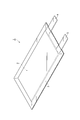
- FIG. 1 is a perspective view showing the secondary battery according to the first embodiment.
- the secondary battery 1 includes an electrode group 2 composed of a positive electrode, a negative electrode, and an electrolyte layer, and a bag-shaped battery outer package 3 that houses the electrode group 2.
- a positive electrode current collecting tab 4 and a negative electrode current collecting tab 5 are provided on the positive electrode and the negative electrode, respectively.
- the positive electrode current collecting tab 4 and the negative electrode current collecting tab 5 protrude from the inside of the battery outer package 3 to the outside so that the positive electrode and the negative electrode can be electrically connected to the outside of the secondary battery 1, respectively.
- the battery outer package 3 may be formed of, for example, a laminate film.
- the laminate film may be a laminate film in which a resin film such as a polyethylene terephthalate (PET) film, a metal foil such as aluminum, copper, and stainless steel, and a sealant layer such as polypropylene are laminated in this order.
- PET polyethylene terephthalate
- metal foil such as aluminum, copper, and stainless steel
- sealant layer such as polypropylene
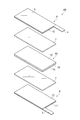
- FIG. 2 is an exploded perspective view showing an embodiment of the electrode group 2 of the secondary battery 1 shown in FIG.
- the electrode group 2A includes a positive electrode 6, an electrolyte layer 7, and a negative electrode 8 in this order.
- the positive electrode 6 includes a current collector 9 and a positive electrode mixture layer 10 provided on the current collector 9.
- the current collector 9 of the positive electrode 6 is provided with a positive electrode current collecting tab 4.
- the negative electrode 8 includes a current collector 11 and a negative electrode mixture layer 12 provided on the current collector 11.
- a current collector tab 5 is provided on the current collector 11 of the negative electrode 8.
- the positive electrode mixture layer 10 and the negative electrode mixture layer 12 are collectively referred to as an electrode mixture layer.
- a positive electrode active material and a negative electrode active material described later are collectively referred to as an electrode active material.
- the electrode group 2A includes a first battery member (positive electrode member) that includes the first current collector 9, the positive electrode mixture layer 10, and the electrolyte layer 7 in this order.
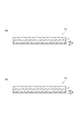
- FIG. 3A is a schematic cross-sectional view showing the first battery member (positive electrode member).
- the first battery member 13 includes a first current collector 9, a positive electrode mixture layer 10 provided on the first current collector 9, and a positive electrode mixture layer.
- 10 is a positive electrode member provided with an electrolyte layer 7 provided on 10 in this order.
- the first current collector 9 may be a metal such as aluminum, titanium, or tantalum, or an alloy thereof.
- the first current collector 9 is preferably aluminum or an alloy thereof because it is lightweight and has a high weight energy density.
- the positive electrode mixture layer 10 contains a positive electrode active material and an ionic liquid.
- the positive electrode active material may be a lithium transition metal compound such as a lithium transition metal oxide or a lithium transition metal phosphate.
- the lithium transition metal oxide may be, for example, lithium manganate, lithium nickelate, lithium cobaltate, or the like.
- Lithium transition metal oxide is a part of transition metals such as Mn, Ni, Co, etc. contained in lithium manganate, lithium nickelate, lithium cobaltate, etc., one or more other transition metals, or A lithium transition metal oxide substituted with a metal element (typical element) such as Mg or Al may also be used. That is, the lithium transition metal oxide may be a compound represented by LiM 1 O 2 or LiM 1 O 4 (M 1 includes at least one transition metal).
- lithium transition metal oxides are Li (Co 1/3 Ni 1/3 Mn 1/3 ) O 2 , LiNi 1/2 Mn 1/2 O 2 , LiNi 1/2 Mn 3/2 O. it may be 4 or the like.
- the lithium transition metal oxide is preferably a compound represented by the following formula (1).
- Lithium transition metal phosphates are LiFePO 4 , LiMnPO 4 , LiMn x M 3 1-x PO 4 (0.3 ⁇ x ⁇ 1, M 3 is Fe, Ni, Co, Ti, Cu, Zn, Mg and Zr) Or at least one element selected from the group consisting of:
- the content of the positive electrode active material may be 70% by mass or more, 80% by mass or more, or 90% by mass or more based on the total amount of the positive electrode mixture layer.
- the content of the positive electrode active material may be 99% by mass or less based on the total amount of the positive electrode mixture layer.
- the ionic liquid contains the following anion component and cation component. Note that the ionic liquid in this specification is a liquid substance at ⁇ 20 ° C. or higher.
- the anion component of the ionic liquid is not particularly limited, but is an anion of a halogen such as Cl ⁇ , Br ⁇ and I ⁇ , an inorganic anion such as BF 4 ⁇ and N (SO 2 F) 2 — , B (C 6 H 5 ) 4 ⁇ , CH 3 SO 3 ⁇ , CF 3 SO 3 ⁇ , N (C 4 F 9 SO 2 ) 2 ⁇ , N (SO 2 CF 3 ) 2 ⁇ , N (SO 2 CF 2 CF 3 ) 2 — and the like It may be an organic anion.
- a halogen such as Cl ⁇ , Br ⁇ and I ⁇
- an inorganic anion such as BF 4 ⁇ and N (SO 2 F) 2 — , B (C 6 H 5 ) 4 ⁇ , CH 3 SO 3 ⁇ , CF 3 SO 3 ⁇ , N (C 4 F 9 SO 2 ) 2 ⁇ , N (SO 2 CF 3 )
- the anionic component of the ionic liquid is preferably B (C 6 H 5 ) 4 ⁇ , CH 3 SO 3 ⁇ , N (C 4 F 9 SO 2 ) 2 ⁇ , CF 3 SO 3 ⁇ , N (SO 2 F) It contains at least one selected from the group consisting of 2 ⁇ , N (SO 2 CF 3 ) 2 —, and N (SO 2 CF 2 CF 3 ) 2 —, and further improves ionic conductivity with a relatively low viscosity.
- the cation component of the ionic liquid is not particularly limited, but is preferably at least one selected from the group consisting of a chain quaternary onium cation, a piperidinium cation, a pyrrolidinium cation, a pyridinium cation, and an imidazolium cation.
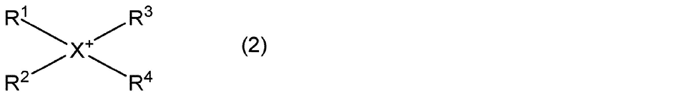
- the chain quaternary onium cation is, for example, a compound represented by the following general formula (2).
- R 1 to R 4 each independently represents a chain alkyl group having 1 to 20 carbon atoms, or a chain alkoxyalkyl group represented by R—O— (CH 2 ) n —.
- R represents a methyl group or an ethyl group, and n represents an integer of 1 to 4
- X represents a nitrogen atom or a phosphorus atom.
- the number of carbon atoms of the alkyl group represented by R 1 to R 4 is preferably 1 to 20, more preferably 1 to 10, and still more preferably 1 to 5.
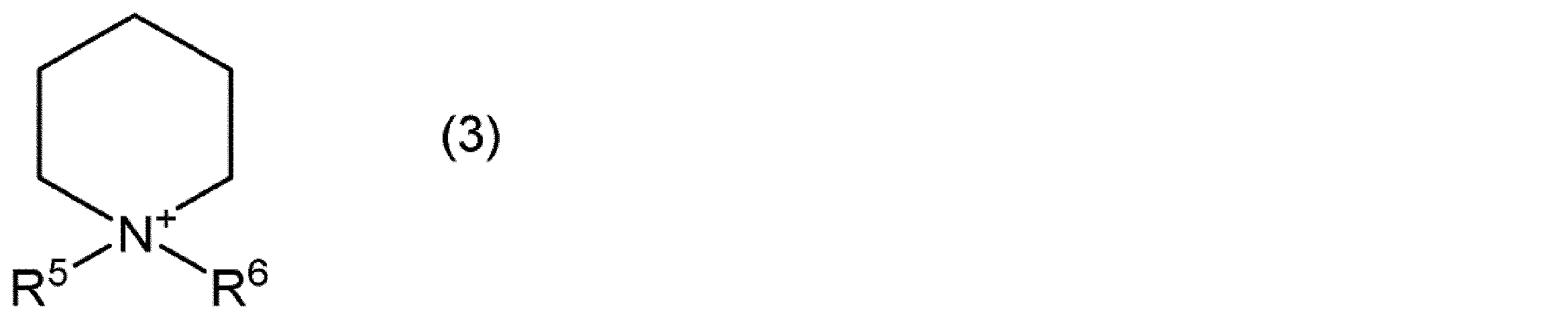
- the piperidinium cation is, for example, a nitrogen-containing six-membered cyclic compound represented by the following general formula (3).
- R 5 and R 6 are each independently an alkyl group having 1 to 20 carbon atoms or an alkoxyalkyl group represented by R—O— (CH 2 ) n — (R is methyl And n represents an integer of 1 to 4.
- the number of carbon atoms of the alkyl group represented by R 5 and R 6 is preferably 1 to 20, more preferably 1 to 10, and still more preferably 1 to 5.
- the pyrrolidinium cation is, for example, a five-membered cyclic compound represented by the following general formula (4).
- R 7 and R 8 are each independently an alkyl group having 1 to 20 carbon atoms, or an alkoxyalkyl group represented by R—O— (CH 2 ) n — (R is methyl And n represents an integer of 1 to 4.
- the carbon number of the alkyl group represented by R 7 and R 8 is preferably 1-20, more preferably 1-10, and still more preferably 1-5.
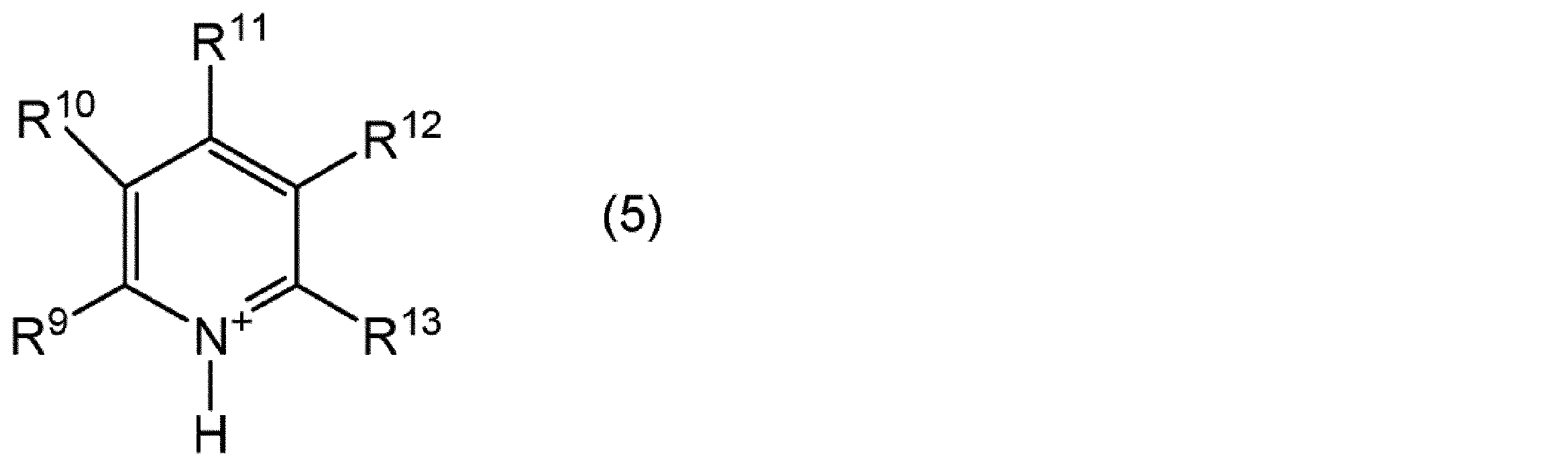
- the pyridinium cation is, for example, a compound represented by the following general formula (5).
- R 9 to R 13 each independently represents an alkyl group having 1 to 20 carbon atoms, an alkoxyalkyl group represented by R—O— (CH 2 ) n — (R represents a methyl group) Or an ethyl group, and n represents an integer of 1 to 4), or a hydrogen atom.
- the number of carbon atoms of the alkyl group represented by R 9 to R 13 is preferably 1 to 20, more preferably 1 to 10, and still more preferably 1 to 5.
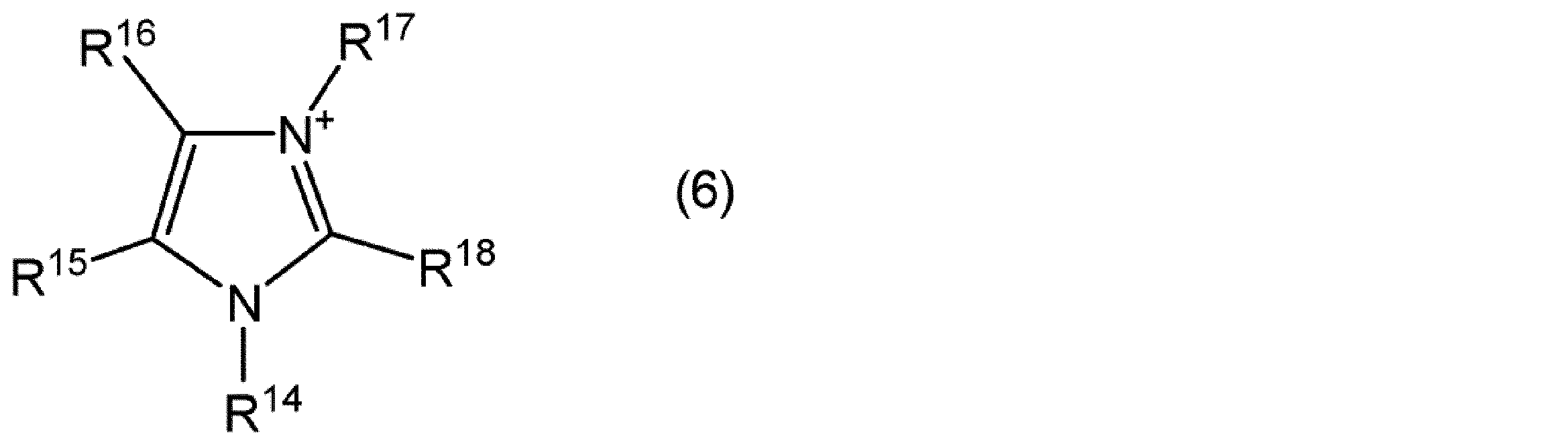
- the imidazolium cation is, for example, a compound represented by the following general formula (6).
- R 14 to R 18 are each independently an alkyl group having 1 to 20 carbon atoms, an alkoxyalkyl group represented by R—O— (CH 2 ) n — (R is a methyl group) Or an ethyl group, and n represents an integer of 1 to 4), or a hydrogen atom.
- the number of carbon atoms of the alkyl group represented by R 14 to R 18 is preferably 1 to 20, more preferably 1 to 10, and still more preferably 1 to 5.
- the content of the ionic liquid contained in the positive electrode mixture layer 10 is preferably 3% by mass or more, more preferably 5% by mass or more, and further preferably 10% by mass or more, based on the total amount of the positive electrode mixture layer. It is.
- the content of the ionic liquid contained in the positive electrode mixture layer 10 is preferably 30% by mass or less, more preferably 25% by mass or less, and further preferably 20% by mass or less, based on the total amount of the positive electrode mixture layer. It is.
- the positive electrode mixture layer 10 may further contain a conductive agent, a binder and the like.
- the conductive agent is not particularly limited, and may be a carbon material such as graphite, acetylene black, carbon black, or carbon fiber.
- the conductive agent may be a mixture of two or more carbon materials described above.
- the content of the conductive agent may be 0.1% by mass or more, 1% by mass or more, or 3% by mass or more based on the total amount of the positive electrode mixture layer, and is 15% by mass or less, 10% by mass or less, or 8 It may be less than mass%.
- the binder is not particularly limited, but contains as a monomer unit at least one selected from the group consisting of ethylene tetrafluoride, vinylidene fluoride, hexafluoropropylene, acrylic acid, maleic acid, ethyl methacrylate, and methyl methacrylate. It may be a polymer, rubber such as styrene-butadiene rubber, isoprene rubber or acrylic rubber.
- the binder is preferably a copolymer containing ethylene tetrafluoride and vinylidene fluoride as structural units.
- An electrolyte salt may be dissolved in the ionic liquid contained in the positive electrode mixture layer 10.
- the electrolyte salt may be at least one selected from the group consisting of a lithium salt, a sodium salt, a calcium salt, and a magnesium salt.
- the anion of the electrolyte salt includes halide ions (I ⁇ , Cl ⁇ , Br ⁇ etc.), SCN ⁇ , BF 4 ⁇ , BF 3 (CF 3 ) ⁇ , BF 3 (C 2 F 5 ) ⁇ , PF 6 ⁇ , ClO 4 ⁇ , SbF 6 ⁇ , N (SO 2 F) 2 ⁇ , N (SO 2 CF 3 ) 2 ⁇ , N (SO 2 C 2 F 5 ) 2 ⁇ , BPh 4 ⁇ , B (C 2 H 4 O 2 ) 2 ⁇ , C (FSO 2 ) 3 ⁇ , C (CF 3 SO 2 ) 3 ⁇ , CF 3 COO ⁇ , CF 3 SO 2 O ⁇ , C 6 F 5 SO 2 O ⁇ , [B (C 2 O 4) 2] - it may be like.
- halide ions I ⁇ , Cl ⁇ , Br ⁇ etc.
- the anion is preferably PF 6 ⁇ , BF 4 ⁇ , N (SO 2 F) 2 ⁇ , N (SO 2 CF 3 ) 2 ⁇ , [B (C 2 O 4 ) 2 ] ⁇ , or ClO 4 ⁇ . is there.
- [FSI] ⁇ N (SO 2 F) 2 ⁇ , bis (fluorosulfonyl) imide anion [TFSI] ⁇ : N (SO 2 CF 3 ) 2 ⁇ , bis (trifluoromethanesulfonyl) imide anion [BOB] ⁇ : [ B (C 2 O 4 ) 2 ] ⁇ , bisoxalate borate anion [f3C] ⁇ : C (FSO 2 ) 3 ⁇ , tris (fluorosulfonyl) carbanion
- Lithium salt is LiPF 6 , LiBF 4 , Li [FSI], Li [TFSI], Li [f 3 C], Li [BOB], LiClO 4 , LiCF 3 BF 3 , LiC 2 F 5 BF 3 , LiC 3 F 7 BF 3 , LiC 4 F 9 BF 3 , Li [C (SO 2 CF 3 ) 3 ], LiCF 3 SO 3 , LiCF 3 COO, and LiRCOO (where R is an alkyl group having 1 to 4 carbon atoms, a phenyl group, or a naphthyl group) And at least one selected from the group consisting of:
- Sodium salts include NaPF 6 , NaBF 4 , Na [FSI], Na [TFSI], Na [f 3 C], Na [BOB], NaClO 4 , NaCF 3 BF 3 , NaC 2 F 5 BF 3 , NaC 3 F 7 BF 3 , NaC 4 F 9 BF 3 , Na [C (SO 2 CF 3 ) 3 ], NaCF 3 SO 3 , NaCF 3 COO, and NaRCOO (where R is an alkyl group having 1 to 4 carbon atoms, a phenyl group, or a naphthyl group) And at least one selected from the group consisting of:
- the calcium salts are Ca (PF 6 ) 2 , Ca (BF 4 ) 2 , Ca [FSI] 2 , Ca [TFSI] 2 , Ca [f3C] 2 , Ca [BOB] 2 , Ca (ClO 4 ) 2 , Ca (CF 3 BF 3 ) 2 , Ca (C 2 F 5 BF 3 ) 2 , Ca (C 3 F 7 BF 3 ) 2 , Ca (C 4 F 9 BF 3 ) 2 , Ca [C (SO 2 CF 3 ) 3 ] 2 , Ca (CF 3 SO 3 ) 2 , Ca (CF 3 COO) 2 , and Ca (RCOO) 2 (R represents an alkyl group having 1 to 4 carbon atoms, a phenyl group, or a naphthyl group.) It may be at least one selected from the group consisting of
- Magnesium salts are Mg (PF 6 ) 2 , Mg (BF 4 ) 2 , Mg [FSI] 2 , Mg [TFSI] 2 , Mg [f 3 C] 2 , Mg [BOB] 2 , Mg (ClO 4 ) 2 , Mg (CF 3 BF 3 ) 2 , Mg (C 2 F 5 BF 3 ) 2 , Mg (C 3 F 7 BF 3 ) 2 , Mg (C 4 F 9 BF 3 ) 2 , Mg [C (SO 2 CF 3 ) 3 ] 2 , Mg (CF 3 SO 3 ) 2 , Mg (CF 3 COO) 2 , and Mg (RCOO) 2 (R represents an alkyl group having 1 to 4 carbon atoms, a phenyl group, or a naphthyl group.) It may be at least one selected from the group consisting of
- the electrolyte salt is preferably LiPF 6 , LiBF 4 , Li [FSI], Li [TFSI], Li [f 3 C], Li [BOB], LiClO 4.
- R is at least one selected from the group consisting of an alkyl group having 1 to 4 carbon atoms, a phenyl group, or a naphthyl group
- LiPF 6. , LiBF 4, Li [BOB] and at least one selected from the group consisting of LiClO 4, more preferably Li [TFSI], and L It is one selected from the group consisting of [FSI].
- the thickness of the positive electrode mixture layer 10 may be 10 ⁇ m or more, 15 ⁇ m or more, or 20 ⁇ m or more.
- the thickness of the positive electrode mixture layer may be 100 ⁇ m or less, 80 ⁇ m or less, or 70 ⁇ m or less.
- the porosity of the positive electrode mixture layer 10 is 10% by volume or less, preferably 5% by volume or less, more preferably 3% by volume or less, and still more preferably 1% with respect to the volume of the positive electrode mixture layer. % By volume or less.
- the porosity of the positive electrode mixture layer is preferably 0.1% by volume or more with respect to the volume of the positive electrode mixture layer.
- the porosity is measured by a mercury intrusion method.
- Conditions for mercury porosimeter measurement in the mercury intrusion method are as follows.
- the electrolyte layer 7 contains, for example, a polymer, oxide particles, an ionic liquid, and at least one electrolyte salt selected from the group consisting of a lithium salt, a sodium salt, a calcium salt, and a magnesium salt.
- the polymer preferably has a first structural unit selected from the group consisting of ethylene tetrafluoride and vinylidene fluoride.
- the polymer preferably contains one or more polymers, and among the structural units constituting the one or more polymers, the first structural unit, hexafluoropropylene, acrylic
- a second structural unit selected from the group consisting of acid, maleic acid, ethyl methacrylate, and methyl methacrylate may be included. That is, the first structural unit and the second structural unit may be included in one kind of polymer to form a copolymer, and each of the first structural unit and the second structural unit may be included in another polymer and have the first structural unit. And at least two types of polymers, the second polymer having the second structural unit.
- the polymer may be polytetrafluoroethylene, polyvinylidene fluoride, a copolymer of vinylidene fluoride and hexafluoropropylene, or the like.
- the content of the polymer is preferably 3% by mass or more based on the total amount of the electrolyte layer.
- the content of the polymer is preferably 50% by mass or less, more preferably 40% by mass or less, based on the total amount of the electrolyte layer.
- the content of the polymer is preferably 3 to 50% by mass or 3 to 40% by mass based on the total amount of the electrolyte layer.
- the oxide particles are, for example, Li, Na, Mg, Al, Si, K, Ca, Sc, Ti, V, Cr, Mn, Fe, Co, Ni, Cu, Zn, Rb, Sr, Y, Nb, Zr. , Mo, Ag, Cd, In, Sn, Sb, Cs, Ba, La, Ta, Hf, W, Ir, Tl, Pb, and Bi.
- the oxide particles include silicon oxide, titanium oxide, zinc oxide, aluminum oxide, zirconium oxide, hafnium oxide, niobium oxide, tantalum oxide, magnesium oxide, calcium oxide, strontium oxide, barium oxide, indium oxide, and oxide. It may be lead or the like.
- the oxide particles may be rare earth metal oxides.
- the oxide particles include scandium oxide, yttrium oxide, lanthanum oxide, cerium oxide, praseodymium oxide, neodymium oxide, samarium oxide, eurobium oxide, gadolinium oxide, terbium oxide, dysprosium oxide, holmium oxide, erbium oxide, and oxide. It may be thulium, ytterbium oxide, lutetium oxide or the like.
- the oxide particles are preferably iron oxide, zirconium oxide, tin oxide, tungsten oxide, titanium oxide, silicon oxide, zinc oxide, or aluminum oxide.
- the average particle diameter of the oxide particles is preferably 0.005 ⁇ m or more, more preferably 0.01 ⁇ m or more, and further preferably 0.05 ⁇ m or more.
- the average particle diameter of the oxide particles is preferably 5 ⁇ m or less, more preferably 3 ⁇ m or less, and even more preferably 1 ⁇ m or less.
- the average particle diameter of the oxide particles is preferably 0.005 to 5 ⁇ m, 0.01 to 3 ⁇ m, or 0.05 to 1 ⁇ m.
- the average particle diameter of the oxide particles is measured by a laser diffraction method, and corresponds to the particle diameter at which the volume accumulation is 50% when the volume accumulation particle size distribution curve is drawn from the small particle diameter side.
- the content of the oxide particles is preferably 5% by mass or more, more preferably 10% by mass or more, still more preferably 15% by mass or more, and particularly preferably 20% by mass based on the total amount of the electrolyte layer. In addition, it is preferably 60% by mass or less, more preferably 50% by mass or less, and still more preferably 40% by mass or less.
- the content of the oxide particles is preferably 5 to 60% by mass, 10 to 60% by mass, 15 to 60% by mass, 20 to 60% by mass, 5 to 50% by mass, 10 to 50% by mass, and 15 to 50% by mass. %, 20-50 mass%, 5-40 mass%, 10-40 mass%, 15-40 mass%, or 20-40 mass%.
- the ionic liquid contained in the electrolyte layer 7 may be the same as the ionic liquid contained in the positive electrode mixture layer described above.
- the content of the ionic liquid contained in the electrolyte layer 7 is preferably 25% by mass or more, more preferably 30% by mass or more, and further preferably 40% by mass or more, based on the total amount of the electrolyte layer.
- the content of the ionic liquid contained in the electrolyte layer 7 may be 80% by mass or less, preferably 70% by mass or less, more preferably 65% by mass or less, and still more preferably based on the total amount of the electrolyte layer. Is 60% by mass or less.
- the electrolyte salt contained in the electrolyte layer 7 may be the same as the electrolyte salt described above, and may be at least one selected from the group consisting of a lithium salt, a sodium salt, a calcium salt, and a magnesium salt.
- the electrolyte salt is preferably one kind selected from the group consisting of an imide lithium salt, an imide sodium salt, an imide calcium salt, and an imide magnesium salt.
- the imide-based lithium salt may be Li [TFSI], Li [FSI], or the like.
- the imide-based sodium salt may be Na [TFSI], Na [FSI] or the like.
- the imide-based calcium salt may be Ca [TFSI] 2 , Ca [FSI] 2 or the like.
- the imide-based magnesium salt may be Mg [TFSI] 2 , Mg [FSI] 2 or the like.
- the concentration of the electrolyte salt per unit volume of the ionic liquid in the electrolyte layer 7 is preferably 0.5 mol / L or more, more preferably 0.7 mol / L or more, from the viewpoint of further improving the charge / discharge characteristics. More preferably, it is 0.8 mol / L or more, Preferably it is 2.0 mol / L or less, More preferably, it is 1.8 mol / L or less, More preferably, it is 1.5 mol / L or less.
- the thickness of the electrolyte layer 7 is preferably 5 ⁇ m or more, more preferably 10 ⁇ m or more, from the viewpoint of increasing strength and improving safety.
- the thickness of the electrolyte layer 7 is preferably 200 ⁇ m or less, more preferably 150 ⁇ m or less, and even more preferably 100 ⁇ m or less, from the viewpoint of further reducing the internal resistance of the secondary battery and further improving the large current characteristics. It is.
- the electrode group 2A includes a second battery member (negative electrode member) that includes the second current collector 11, the negative electrode mixture layer 12, and the electrolyte layer 7 in this order. You can also see it.
- FIG. 3B is a schematic cross-sectional view showing the second battery member (negative electrode member). As shown in FIG. 3B, the second battery member includes a second current collector 11, a negative electrode mixture layer 12 provided on the second current collector 11, and a negative electrode mixture layer 12. It is a negative electrode member provided with the electrolyte layer 7 provided on this order. Since the electrolyte layer 7 is the same as the electrolyte layer 7 in the first battery member 13 described above, description thereof is omitted below.
- the second current collector 11 may be a metal such as aluminum, copper, nickel, stainless steel, or an alloy thereof. Since the second current collector 11 is light and has a high weight energy density, it is preferably aluminum or an alloy thereof. The second current collector 11 is preferably copper from the viewpoint of ease of processing into a thin film and cost.
- the negative electrode mixture layer 12 contains a negative electrode active material and an ionic liquid.
- the negative electrode active material may be a carbon material such as graphite or amorphous carbon, a metal material containing tin, silicon, or the like, lithium titanate (Li 4 Ti 5 O 12 ), metallic lithium, or the like.
- the content of the negative electrode active material may be 60% by mass or more, 65% by mass or more, or 70% by mass or more based on the total amount of the negative electrode mixture layer.
- the content of the negative electrode active material may be 99% by mass or less, 95% by mass or less, or 90% by mass or less based on the total amount of the negative electrode mixture layer.
- the ionic liquid contained in the negative electrode mixture layer 12 may be the same as the ionic liquid contained in the positive electrode mixture layer 10 described above.
- the content of the ionic liquid contained in the negative electrode mixture layer 12 is preferably 3% by mass or more, more preferably 5% by mass or more, and further preferably 10% by mass or more, based on the total amount of the negative electrode mixture layer. It is.
- the content of the ionic liquid contained in the negative electrode mixture layer 12 is preferably 30% by mass or less, more preferably 25% by mass or less, and further preferably 20% by mass or less, based on the total amount of the negative electrode mixture layer. It is.
- the negative electrode mixture layer 12 may further contain a conductive agent, a binder, and the like that can be used for the positive electrode mixture layer 10 described above.
- an electrolyte salt similar to the electrolyte salt that can be used for the positive electrode mixture layer 10 described above may be dissolved.
- the thickness of the negative electrode mixture layer 12 may be 10 ⁇ m or more, 15 ⁇ m or more, or 20 ⁇ m or more.
- the thickness of the negative electrode mixture layer may be 60 ⁇ m or less, 55 ⁇ m or less, or 50 ⁇ m or less.
- the porosity of the negative electrode mixture layer 12 is 10% by volume or less, preferably 5% by volume or less, more preferably 3% by volume or less, and still more preferably 1% with respect to the volume of the negative electrode mixture layer. % By volume or less.
- the porosity of the negative electrode mixture layer 12 is preferably 0.1% by volume or more with respect to the volume of the negative electrode mixture layer.
- the manufacturing method of the secondary battery 1 mentioned above includes a first step of forming the positive electrode mixture layer 10 on the first current collector 9 to obtain the positive electrode 6, and a second current collector 11.
- a second step of obtaining the negative electrode 8 by forming the negative electrode mixture layer 12 thereon, and a third step of providing the electrolyte layer 7 between the positive electrode 6 and the negative electrode 8 are included.
- the positive electrode mixture is applied to the first current collector 9. And dried.
- the dispersion medium is preferably an organic solvent such as N-methyl-2-pyrrolidone.
- the method of applying the positive electrode mixture to the first current collector 9 is, for example, a method of applying using an applicator, a metal mask printing method, an electrostatic coating method, a dip coating method, a spray coating method, a roll coating method, It is a known coating method such as a gravure coating method or a screen printing method.
- the method of drying the positive electrode mixture applied on the first current collector 9 may be a method using an infrared heater, hot air, or the like, and these methods are used alone or in combination. It's okay.
- the positive electrode may be further dried by placing it under vacuum.
- the positive electrode after drying can be made to have a porosity of the positive electrode mixture layer 10 of 10% by volume or less by subjecting the positive electrode to pressure treatment by a flat plate pressing method, a calender roll method or the like.
- the porosity of the positive electrode mixture layer 10 is adjusted by adjusting the thickness of the positive electrode mixture layer 10 by pressing with a predetermined gap using a roll press machine capable of adjusting the gap. Can be made 10 volume% or less.
- the press section may be heated. By heating the press portion, for example, the binder in the positive electrode mixture is softened, and the porosity can be easily adjusted.
- the negative electrode is obtained by the same method as in the first step described above. That is, it is obtained by dispersing a material used for the negative electrode mixture layer 12 in a dispersion medium to obtain a slurry-like negative electrode mixture, and then applying the negative electrode mixture to the second current collector 11 and drying it. .
- the porosity of the negative electrode mixture layer 12 can be reduced to 10% by volume or less by the same method as in the first step.
- the electrolyte layer 7 is a sheet obtained by kneading the material used for the electrolyte layer 7 and then sandwiching it with a resin formed into a sheet shape such as polytetrafluoroethylene and pressing it with a roll. Obtained as an electrolyte layer.
- the secondary battery 1 is obtained by laminating the positive electrode 6, the electrolyte layer 7 and the negative electrode 8 by, for example, laminating.
- the electrolyte layer 7 is positioned on the positive electrode mixture layer 10 side of the positive electrode 6 and on the negative electrode mixture layer 12 side of the negative electrode 8, that is, the first current collector 9, the positive electrode mixture layer 10, and the electrolyte.
- Layer 7, negative electrode mixture layer 12, and second current collector 11 are laminated in this order.
- the electrolyte layer 7 is formed on at least one of the surface of the positive electrode 6 on the positive electrode mixture layer 10 side and the surface of the negative electrode 8 on the negative electrode mixture layer 12 side.
- the above-described sheet-like electrolyte layer may be laminated on the positive electrode mixture layer 10 side of the positive electrode 6 by lamination.
- pressurization such as heat treatment or press treatment is performed. Processing may be performed.
- the 1st battery member 13 positive electrode member
- the secondary battery 1 is obtained by laminating
- the above-described sheet-like electrolyte layer may be laminated on the negative electrode mixture layer 12 side of the negative electrode 8 by lamination.
- pressurization such as heat treatment or press treatment Processing may be performed.
- the 2nd battery member 14 negative electrode member
- the secondary battery 1 is obtained by laminating
- the electrolyte layer 7 is formed on both the surface of the positive electrode 6 on the side of the positive electrode mixture layer 10 and on the surface of the negative electrode 8 on the side of the negative electrode mixture layer 12 by the above-described method.
- the secondary battery 1 can be obtained by laminating both battery members so that the electrolyte layers 7 are in contact with each other.
- FIG. 4 is an exploded perspective view showing an electrode group of the secondary battery according to the second embodiment.
- the same reference numerals as those in the first embodiment are given, and redundant description is omitted.
- the secondary battery in the second embodiment is different from the secondary battery in the first embodiment in that the electrode group 2 ⁇ / b> B further includes a bipolar electrode 15. That is, the electrode group 2B includes the positive electrode 6, the first electrolyte layer 7, the bipolar electrode 15, the second electrolyte layer 7, and the negative electrode 8 in this order.
- the bipolar electrode 15 includes a third current collector 16, a positive electrode mixture layer 10 provided on a surface of the third current collector 16 on the negative electrode 8 side, and a positive electrode 6 side of the third current collector 16. And a negative electrode mixture layer 12 provided on the surface.
- a third battery member (bipolar electrode member) provided with the first electrolyte layer 7, the bipolar electrode 15, and the second electrolyte layer 7 in this order in the electrode group 2B.
- FIG. 5 is a schematic cross-sectional view showing a third battery member (bipolar electrode member).
- the third battery member 17 includes a third current collector 16, a positive electrode mixture layer 10 provided on one surface of the third current collector 16, and a positive electrode mixture.
- the third current collector 16 is formed of, for example, a single metal such as aluminum, stainless steel, or titanium, or a clad material formed by rolling and joining aluminum and copper or stainless steel and copper.
- the first electrolyte layer 7 and the second electrolyte layer 7 may be the same type or different types, and preferably the same type.
- Example 1 ⁇ Preparation of electrolyte layer> Lithium bis (fluorosulfonyl) imide (Li [FSI]) dried under a dry argon atmosphere was used as an electrolyte salt, and N-methyl-N-propylpyrrolidinium bis (fluorosulfonyl) imide (Py13FSI) as an ionic liquid was used.
- the electrolyte salt was dissolved at a concentration of 1 mol / L (hereinafter, when expressing the composition of the ionic liquid in which the electrolyte salt was dissolved, “concentration of lithium salt / type of lithium salt / type of ionic liquid”) May be indicated).
- the ionic liquid in which the electrolyte salt is dissolved as described above and the SiO 2 particles (average particle size 0.1 ⁇ m) are mixed in methanol at a volume ratio (ionic liquid in which the electrolyte salt is dissolved: SiO 2 ) 80:20. Mixing with stirring for 30 minutes or more. Then, it distilled at 60 degreeC using the evaporator.
- the composition obtained by distillation and polytetrafluoroethylene were mixed at a mass ratio (composition: polytetrafluoroethylene) 95: 5 and kneaded for 30 minutes or more using a mortar to obtain an electrolyte composition. .
- the obtained electrolyte composition was sandwiched between two polytetrafluoroethylene (PTFE) sheets and pressed with a roll press machine to obtain an electrolyte sheet having a thickness of 200 ⁇ m.
- This electrolyte sheet was punched into ⁇ 16 mm to form an electrolyte layer.
- the content of polytetrafluoroethylene, the content of SiO 2 particles, and the total content of ionic liquid and lithium salt in the electrolyte layer are 13% by mass, 25% by mass, and 62% by mass based on the total amount of the electrolyte layer, respectively. %Met.
- This positive electrode mixture slurry was applied on a current collector (a 20 ⁇ m thick aluminum foil) at a coating amount of 160 g / m 2 and dried at 80 ° C.
- the positive electrode mixture having a mixture density of 2.82 g / cm 3 (porosity 0.22%) is obtained by adjusting the thickness of the positive electrode mixture layer by pressing the positive electrode with a roll press capable of adjusting the gap. A layer was formed. This was punched to 15 mm to make a positive electrode.
- a negative electrode mixture slurry was prepared by mixing 10 parts by mass of a copolymer solution (solid content 12% by mass) and 14 parts by mass of an ionic liquid (1M / Li [FSI] / Py13FSI) in which an electrolyte salt was dissolved.
- This negative electrode mixture slurry was coated on a current collector (copper foil having a thickness of 10 ⁇ m) at a coating amount of 90 g / m 2 and dried at 80 ° C.
- a current collector copper foil having a thickness of 10 ⁇ m
- the thickness of the negative electrode mixture layer is adjusted, and the negative electrode mixture having a mixture density of 2.97 g / cm 3 (porosity 0.64%).
- a layer was formed. This was punched to ⁇ 16 mm to form a negative electrode.
- An evaluation coin battery was prepared using the positive electrode, the electrolyte layer, and the negative electrode.
- the positive electrode, the electrolyte layer, and the negative electrode were stacked in this order and placed in a CR2032-type coin cell container, and then the upper part of the battery container was crimped and sealed through an insulating gasket.
- Example 2 By pressing with a roll press capable of adjusting the gap, the thickness of the positive electrode mixture layer is adjusted, and the mixture density of the positive electrode mixture layer is 2.80 g / cm 3 (porosity 0.93%).
- a coin-type battery was produced in the same manner as in Example 1 except that.
- Example 3 By pressing with a roll press capable of adjusting the gap, the thickness of the positive electrode mixture layer is adjusted, and the mixture density of the positive electrode mixture layer is 2.75 g / cm 3 (porosity 2.70%).
- a coin-type battery was produced in the same manner as in Example 1 except that.
- Example 4 By pressing with a roll press capable of adjusting the gap, the thickness of the positive electrode mixture layer is adjusted, and the mixture density of the positive electrode mixture layer is 2.70 g / cm 3 (porosity 4.47%).
- a coin-type battery was produced in the same manner as in Example 1 except that.
- Example 5 By pressing with a roll press machine capable of adjusting the gap, the thickness of the positive electrode mixture layer is adjusted, and the mixture density of the positive electrode mixture layer is 2.65 g / cm 3 (porosity 6.24%).
- a coin-type battery was produced in the same manner as in Example 1 except that.
- Example 6 By pressing with a roll press machine capable of adjusting the gap, the thickness of the positive electrode mixture layer is adjusted, and the mixture density of the positive electrode mixture layer is 2.55 g / cm 3 (porosity 9.78%).
- a coin-type battery was produced in the same manner as in Example 1 except that.
- Example 7 By pressing with a roll press machine capable of adjusting the gap, the thickness of the negative electrode mixture layer is adjusted, and the mixture density of the negative electrode mixture layer is 1.94 g / cm 3 (porosity 2.15%).
- a coin-type battery was produced in the same manner as in Example 1 except that.
- Example 8 By pressing with a roll press capable of adjusting the gap, the thickness of the negative electrode mixture layer is adjusted, and the mixture density of the negative electrode mixture layer is 1.90 g / cm 3 (porosity 4.17%).
- a coin-type battery was produced in the same manner as in Example 1 except that.
- Example 9 By pressing with a roll press machine capable of adjusting the gap, the thickness of the negative electrode mixture layer is adjusted, and the mixture density of the negative electrode mixture layer is 1.80 g / cm 3 (porosity 9.22%).
- a coin-type battery was produced in the same manner as in Example 1 except that.
- Example 10 A coin-type battery was produced in the same manner as in Example 1 except that 1-ethyl-3-methyl-imidazolium bis (fluorosulfonyl) imide (EMIFSI) was used as the ionic liquid in the production of the electrolyte layer of Example 1. did.
- EMIFSI 1-ethyl-3-methyl-imidazolium bis (fluorosulfonyl) imide
- Example 11 A coin-type battery was produced in the same manner as in Example 1 except that SiO 2 particles (average particle diameter: 1.0 ⁇ m) were used as oxide particles in the production of the electrolyte layer of Example 1.
- Example 12 A coin-type battery was produced in the same manner as in Example 1 except that SiO 2 particles (average particle size: 3.0 ⁇ m) were used as oxide particles in the production of the electrolyte layer of Example 1.
- Example 13 A coin-type battery was produced in the same manner as in Example 1 except that CeO 2 particles (average particle size: 0.02 ⁇ m) were used as oxide particles in the production of the electrolyte layer of Example 1.
- Example 14 A coin-type battery was produced in the same manner as in Example 1 except that in the production of the electrolyte layer of Example 1, a copolymer of vinylidene fluoride and hexafluoropropylene was used as the polymer.
- Example 15 A coin-type battery was produced in the same manner as in Example 14 except that CeO 2 particles (average particle diameter: 0.02 ⁇ m) were used as oxide particles in the production of the electrolyte layer of Example 14.
- Example 16 A coin-type battery was produced in the same manner as in Example 1 except that polyvinylidene fluoride was used as the polymer in the production of the electrolyte layer of Example 1.
Abstract
Description
図1は、第1実施形態に係る二次電池を示す斜視図である。図1に示すように、二次電池1は、正極、負極及び電解質層から構成される電極群2と、電極群2を収容する袋状の電池外装体3とを備えている。正極及び負極には、それぞれ正極集電タブ4及び負極集電タブ5が設けられている。正極集電タブ4及び負極集電タブ5は、それぞれ正極及び負極が二次電池1の外部と電気的に接続可能なように、電池外装体3の内部から外部へ突き出している。 [First Embodiment]
FIG. 1 is a perspective view showing the secondary battery according to the first embodiment. As shown in FIG. 1, the
LiaNibCocM2 dO2+e (1)
[式(1)中、M2は、Al、Mn、Mg及びCaからなる群より選ばれる少なくとも1種であり、a、b、c、d及びeは、それぞれ0.2≦a≦1.2、0.5≦b≦0.9、0.1≦c≦0.4、0≦d≦0.2、-0.2≦e≦0.2、かつb+c+d=1を満たす数である。] From the viewpoint of further improving the energy density, the lithium transition metal oxide is preferably a compound represented by the following formula (1).
Li a Ni b Co c M 2 d
Wherein (1), M 2 is at least one Al, Mn, selected from the group consisting of Mg and Ca, a, b, c, d and e are each 0.2 ≦ a ≦ 1. 2, 0.5 ≦ b ≦ 0.9, 0.1 ≦ c ≦ 0.4, 0 ≦ d ≦ 0.2, −0.2 ≦ e ≦ 0.2, and b + c + d = 1. . ]

[FSI]-:N(SO2F)2 -、ビス(フルオロスルホニル)イミドアニオン
[TFSI]-:N(SO2CF3)2 -、ビス(トリフルオロメタンスルホニル)イミドアニオン
[BOB]-:[B(C2O4)2]-、ビスオキサレートボラートアニオン
[f3C]-:C(FSO2)3 -、トリス(フルオロスルホニル)カルボアニオン In the following, the following abbreviations may be used.
[FSI] − : N (SO 2 F) 2 − , bis (fluorosulfonyl) imide anion [TFSI] − : N (SO 2 CF 3 ) 2 − , bis (trifluoromethanesulfonyl) imide anion [BOB] − : [ B (C 2 O 4 ) 2 ] − , bisoxalate borate anion [f3C] − : C (FSO 2 ) 3 − , tris (fluorosulfonyl) carbanion
装置:オートポアIV 9500(株式会社島津製作所)
水銀の表面張力:475dynes/cm
水銀の密度:13.534g/mL The porosity is measured by a mercury intrusion method. Conditions for mercury porosimeter measurement in the mercury intrusion method are as follows.
Equipment: Autopore IV 9500 (Shimadzu Corporation)
Mercury surface tension: 475 dynes / cm
Mercury density: 13.534 g / mL
次に、第2実施形態に係る二次電池について説明する。図4は、第2実施形態に係る二次電池の電極群を示す分解斜視図である。図4では、第1実施形態と同一の符号を付し、重複する説明は省略する。図4に示すように、第2実施形態における二次電池が第1実施形態における二次電池と異なる点は、電極群2Bが、バイポーラ電極15を更に備えている点である。すなわち、電極群2Bは、正極6と、第1の電解質層7と、バイポーラ電極15と、第2の電解質層7と、負極8とをこの順に備えている。 [Second Embodiment]
Next, the secondary battery according to the second embodiment will be described. FIG. 4 is an exploded perspective view showing an electrode group of the secondary battery according to the second embodiment. In FIG. 4, the same reference numerals as those in the first embodiment are given, and redundant description is omitted. As shown in FIG. 4, the secondary battery in the second embodiment is different from the secondary battery in the first embodiment in that the
<電解質層の作製>
乾燥アルゴン雰囲気下で乾燥したリチウムビス(フルオロスルホニル)イミド(Li[FSI])を電解質塩として用い、イオン液体であるN-メチル-N-プロピルピロリジニウムビス(フルオロスルホニル)イミド(Py13FSI)に、電解質塩を1mol/Lの濃度で溶解させた(以下、電解質塩を溶解させたイオン液体の組成を表す際に、「リチウム塩の濃度/リチウム塩の種類/イオン液体の種類」のように表記することがある)。上記のように電解質塩を溶解させたイオン液体とSiO2粒子(平均粒子径0.1μm)とを、体積比(電解質塩を溶解させたイオン液体:SiO2)80:20で、メタノール中で30分以上攪拌しながら混合した。その後、エバポレータを用いて60℃で蒸留した。蒸留により得られた組成物と、ポリ四フッ化エチレンを質量比(組成物:ポリ四フッ化エチレン)95:5で混合し、乳鉢を用いて30分以上混練し、電解質組成物を得た。得られた電解質組成物を2枚のポリ四フッ化エチレン(PTFE)シート間にはさみ、ロールプレス機でプレスすることにより、厚さ200μmの電解質シートを得た。この電解質シートをφ16mmに打ち抜き、電解質層とした。この電解質層におけるポリ四フッ化エチレンの含有量、SiO2粒子の含有量及びイオン液体とリチウム塩の合計の含有量は、電解質層全量を基準として、それぞれ13質量%、25質量%、62質量%であった。 [Example 1]
<Preparation of electrolyte layer>
Lithium bis (fluorosulfonyl) imide (Li [FSI]) dried under a dry argon atmosphere was used as an electrolyte salt, and N-methyl-N-propylpyrrolidinium bis (fluorosulfonyl) imide (Py13FSI) as an ionic liquid was used. The electrolyte salt was dissolved at a concentration of 1 mol / L (hereinafter, when expressing the composition of the ionic liquid in which the electrolyte salt was dissolved, “concentration of lithium salt / type of lithium salt / type of ionic liquid”) May be indicated). The ionic liquid in which the electrolyte salt is dissolved as described above and the SiO 2 particles (average particle size 0.1 μm) are mixed in methanol at a volume ratio (ionic liquid in which the electrolyte salt is dissolved: SiO 2 ) 80:20. Mixing with stirring for 30 minutes or more. Then, it distilled at 60 degreeC using the evaporator. The composition obtained by distillation and polytetrafluoroethylene were mixed at a mass ratio (composition: polytetrafluoroethylene) 95: 5 and kneaded for 30 minutes or more using a mortar to obtain an electrolyte composition. . The obtained electrolyte composition was sandwiched between two polytetrafluoroethylene (PTFE) sheets and pressed with a roll press machine to obtain an electrolyte sheet having a thickness of 200 μm. This electrolyte sheet was punched into φ16 mm to form an electrolyte layer. The content of polytetrafluoroethylene, the content of SiO 2 particles, and the total content of ionic liquid and lithium salt in the electrolyte layer are 13% by mass, 25% by mass, and 62% by mass based on the total amount of the electrolyte layer, respectively. %Met.
層状型リチウム・ニッケル・マンガン・コバルト複合酸化物(正極活物質)70質量部、アセチレンブラック(導電剤、平均粒径48nm、製品名:HS-100、デンカ株式会社)7質量部、フッ化ビニリデンとヘキサフルオロプロピレンとのコポリマ溶液(固形分12質量%)9質量部、電解質塩を溶解させたイオン液体(1M/Li[FSI]/Py13FSI)14質量部を混合して正極合剤スラリーを調製した。この正極合剤スラリーを集電体(厚さ20μmのアルミニウム箔)上に塗工量160g/m2で塗工し、80℃で乾燥させた。この正極をギャップ調整が可能なロールプレス機でプレスすることにより、正極合剤層の厚さを調節して、合剤密度2.82g/cm3(空隙率0.22%)の正極合剤層を形成した。これをφ15mmに打ち抜き、正極とした。 <Preparation of positive electrode>
Layered lithium / nickel / manganese / cobalt composite oxide (positive electrode active material) 70 parts by mass, acetylene black (conductive agent, average particle size 48 nm, product name: HS-100, Denka Co., Ltd.) 7 parts by mass,
黒鉛(負極活物質、日立化成株式会社製)74質量部、アセチレンブラック(導電剤、平均粒径48nm、製品名:HS-100、デンカ株式会社)2質量部、フッ化ビニリデンとヘキサフルオロプロピレンのコポリマ溶液(固形分12質量%)10質量部、電解質塩を溶解させたイオン液体(1M/Li[FSI]/Py13FSI)14質量部を混合して負極合剤スラリーを調製した。この負極合剤スラリーを集電体(厚さ10μmの銅箔)上に塗工量90g/m2で塗工し、80℃で乾燥させた。この負極をギャップ調整が可能なロールプレス機でプレスすることにより、負極合剤層の厚さを調節して、合剤密度2.97g/cm3(空隙率0.64%)の負極合剤層を形成した。これをφ16mmに打ち抜き、負極とした。 <Production of negative electrode>
74 parts by mass of graphite (negative electrode active material, manufactured by Hitachi Chemical Co., Ltd.), 2 parts by mass of acetylene black (conductive agent, average particle size 48 nm, product name: HS-100, Denka Co., Ltd.), vinylidene fluoride and hexafluoropropylene A negative electrode mixture slurry was prepared by mixing 10 parts by mass of a copolymer solution (
正極、電解質層、負極を用いて評価用コイン電池を作製した。正極、電解質層、負極をこの順に重ね、CR2032型のコインセル容器内に配置した後、絶縁性のガスケットを介して電池容器上部をかしめて密閉した。 <Production of coin cell for evaluation>
An evaluation coin battery was prepared using the positive electrode, the electrolyte layer, and the negative electrode. The positive electrode, the electrolyte layer, and the negative electrode were stacked in this order and placed in a CR2032-type coin cell container, and then the upper part of the battery container was crimped and sealed through an insulating gasket.
ギャップ調整が可能なロールプレス機でプレスすることにより、正極合剤層の厚さを調節して、正極合剤層の合剤密度を2.80g/cm3(空隙率0.93%)とした以外は、実施例1と同様にしてコイン型電池を作製した。 [Example 2]
By pressing with a roll press capable of adjusting the gap, the thickness of the positive electrode mixture layer is adjusted, and the mixture density of the positive electrode mixture layer is 2.80 g / cm 3 (porosity 0.93%). A coin-type battery was produced in the same manner as in Example 1 except that.
ギャップ調整が可能なロールプレス機でプレスすることにより、正極合剤層の厚さを調節して、正極合剤層の合剤密度を2.75g/cm3(空隙率2.70%)とした以外は実施例1と同様にしてコイン型電池を作製した。 [Example 3]
By pressing with a roll press capable of adjusting the gap, the thickness of the positive electrode mixture layer is adjusted, and the mixture density of the positive electrode mixture layer is 2.75 g / cm 3 (porosity 2.70%). A coin-type battery was produced in the same manner as in Example 1 except that.
ギャップ調整が可能なロールプレス機でプレスすることにより、正極合剤層の厚さを調節して、正極合剤層の合剤密度を2.70g/cm3(空隙率4.47%)とした以外は実施例1と同様にしてコイン型電池を作製した。 [Example 4]
By pressing with a roll press capable of adjusting the gap, the thickness of the positive electrode mixture layer is adjusted, and the mixture density of the positive electrode mixture layer is 2.70 g / cm 3 (porosity 4.47%). A coin-type battery was produced in the same manner as in Example 1 except that.
ギャップ調整が可能なロールプレス機でプレスすることにより、正極合剤層の厚さを調節して、正極合剤層の合剤密度を2.65g/cm3(空隙率6.24%)とした以外は実施例1と同様にしてコイン型電池を作製した。 [Example 5]
By pressing with a roll press machine capable of adjusting the gap, the thickness of the positive electrode mixture layer is adjusted, and the mixture density of the positive electrode mixture layer is 2.65 g / cm 3 (porosity 6.24%). A coin-type battery was produced in the same manner as in Example 1 except that.
ギャップ調整が可能なロールプレス機でプレスすることにより、正極合剤層の厚さを調節して、正極合剤層の合剤密度を2.55g/cm3(空隙率9.78%)とした以外は実施例1と同様にしてコイン型電池を作製した。 [Example 6]
By pressing with a roll press machine capable of adjusting the gap, the thickness of the positive electrode mixture layer is adjusted, and the mixture density of the positive electrode mixture layer is 2.55 g / cm 3 (porosity 9.78%). A coin-type battery was produced in the same manner as in Example 1 except that.
ギャップ調整が可能なロールプレス機でプレスすることにより、負極合剤層の厚さを調節して、負極合剤層の合剤密度を1.94g/cm3(空隙率2.15%)とした以外は実施例1と同様にしてコイン型電池を作製した。 [Example 7]
By pressing with a roll press machine capable of adjusting the gap, the thickness of the negative electrode mixture layer is adjusted, and the mixture density of the negative electrode mixture layer is 1.94 g / cm 3 (porosity 2.15%). A coin-type battery was produced in the same manner as in Example 1 except that.
ギャップ調整が可能なロールプレス機でプレスすることにより、負極合剤層の厚さを調節して、負極合剤層の合剤密度を1.90g/cm3(空隙率4.17%)とした以外は実施例1と同様にしてコイン型電池を作製した。 [Example 8]
By pressing with a roll press capable of adjusting the gap, the thickness of the negative electrode mixture layer is adjusted, and the mixture density of the negative electrode mixture layer is 1.90 g / cm 3 (porosity 4.17%). A coin-type battery was produced in the same manner as in Example 1 except that.
ギャップ調整が可能なロールプレス機でプレスすることにより、負極合剤層の厚さを調節して、負極合剤層の合剤密度を1.80g/cm3(空隙率9.22%)とした以外は実施例1と同様にしてコイン型電池を作製した。 [Example 9]
By pressing with a roll press machine capable of adjusting the gap, the thickness of the negative electrode mixture layer is adjusted, and the mixture density of the negative electrode mixture layer is 1.80 g / cm 3 (porosity 9.22%). A coin-type battery was produced in the same manner as in Example 1 except that.
実施例1の電解質層の作製において、イオン液体として1-エチル-3-メチル-イミダゾリウムビス(フルオロスルホニル)イミド(EMIFSI)を用いた以外は、実施例1と同様にしてコイン型電池を作製した。 [Example 10]
A coin-type battery was produced in the same manner as in Example 1 except that 1-ethyl-3-methyl-imidazolium bis (fluorosulfonyl) imide (EMIFSI) was used as the ionic liquid in the production of the electrolyte layer of Example 1. did.
実施例1の電解質層の作製において、酸化物粒子としてSiO2粒子(平均粒子径:1.0μm)を用いた以外は、実施例1と同様にしてコイン型電池を作製した。 [Example 11]
A coin-type battery was produced in the same manner as in Example 1 except that SiO 2 particles (average particle diameter: 1.0 μm) were used as oxide particles in the production of the electrolyte layer of Example 1.
実施例1の電解質層の作製において、酸化物粒子としてSiO2粒子(平均粒子径:3.0μm)を用いた以外は、実施例1と同様にしてコイン型電池を作製した。 [Example 12]
A coin-type battery was produced in the same manner as in Example 1 except that SiO 2 particles (average particle size: 3.0 μm) were used as oxide particles in the production of the electrolyte layer of Example 1.
実施例1の電解質層の作製において、酸化物粒子としてCeO2粒子(平均粒子径:0.02μm)を用いた以外は、実施例1と同様にしてコイン型電池を作製した。 [Example 13]
A coin-type battery was produced in the same manner as in Example 1 except that CeO 2 particles (average particle size: 0.02 μm) were used as oxide particles in the production of the electrolyte layer of Example 1.
実施例1の電解質層の作製において、ポリマとしてフッ化ビニリデンとヘキサフルオロプロピレンとのコポリマを用いた以外は、実施例1と同様にしてコイン型電池を作製した。 [Example 14]
A coin-type battery was produced in the same manner as in Example 1 except that in the production of the electrolyte layer of Example 1, a copolymer of vinylidene fluoride and hexafluoropropylene was used as the polymer.
実施例14の電解質層の作製において、酸化物粒子としてCeO2粒子(平均粒子径:0.02μm)を用いた以外は、実施例14と同様にしてコイン型電池を作製した。 [Example 15]
A coin-type battery was produced in the same manner as in Example 14 except that CeO 2 particles (average particle diameter: 0.02 μm) were used as oxide particles in the production of the electrolyte layer of Example 14.
実施例1の電解質層の作製において、ポリマとしてポリフッ化ビニリデンを用いた以外は、実施例1と同様にしてコイン型電池を作製した。 [Example 16]
A coin-type battery was produced in the same manner as in Example 1 except that polyvinylidene fluoride was used as the polymer in the production of the electrolyte layer of Example 1.
ギャップ調整が可能なロールプレス機でプレスすることにより、正極合剤層の厚さを調節して、正極合剤層の合剤密度を2.40g/cm3(空隙率15.08%)とした以外は実施例1と同様にしてコイン型電池を作製した。
[参考例2]
ギャップ調整が可能なロールプレス機でプレスすることにより、負極合剤層の厚さを調節して、負極合剤層の合剤密度を1.65g/cm3(空隙率16.78%)とした以外は実施例1と同様にしてコイン型電池を作製した。 [Reference Example 1]
By pressing with a roll press capable of adjusting the gap, the thickness of the positive electrode mixture layer is adjusted, and the mixture density of the positive electrode mixture layer is 2.40 g / cm 3 (porosity 15.08%). A coin-type battery was produced in the same manner as in Example 1 except that.
[Reference Example 2]
By pressing with a roll press capable of adjusting the gap, the thickness of the negative electrode mixture layer is adjusted, and the mixture density of the negative electrode mixture layer is 1.65 g / cm 3 (porosity 16.78%). A coin-type battery was produced in the same manner as in Example 1 except that.
得られた実施例1~13のコイン型電池について、25℃での放電容量を、充放電装置(東洋システム株式会社製)を用いて以下の充放電条件の下で測定した。
(1)終止電圧4.2V、0.05Cで定電流定電圧(CCCV)充電を行った後、0.05Cで終止電圧2.7Vまで定電流(CC)放電するサイクルを1サイクル行い、放電容量を求めた。なお、Cとは「電流値(A)/電池容量(Ah)」を意味する。
(2)次いで、終止電圧4.2V、0.1Cで定電流定電圧(CCCV)充電を行った後、0.5Cで終止電圧2.7Vまで定電流(CC)放電するサイクルを1サイクル行い、放電容量を求めた。
得られた放電容量から、下記式を用いて放電特性(%)を算出した。放電特性は、その値が大きいほど優れているといえる。得られた結果を表1に示す。
放電特性(%)=(2)で得られた放電容量/(1)で得られた放電容量×100 <Evaluation of discharge characteristics>
For the obtained coin-type batteries of Examples 1 to 13, the discharge capacity at 25 ° C. was measured under the following charge / discharge conditions using a charge / discharge device (manufactured by Toyo System Co., Ltd.).
(1) After a constant current constant voltage (CCCV) charge at a final voltage of 4.2 V and 0.05 C, a cycle of discharging a constant current (CC) to a final voltage of 2.7 V at 0.05 C is performed for one cycle. The capacity was determined. C means “current value (A) / battery capacity (Ah)”.
(2) Next, after performing constant current and constant voltage (CCCV) charging at a final voltage of 4.2 V and 0.1 C, one cycle of discharging at a constant current (CC) to 0.5 V at a final voltage of 2.7 V is performed. The discharge capacity was determined.
From the obtained discharge capacity, the discharge characteristic (%) was calculated using the following formula. It can be said that the larger the value, the better the discharge characteristics. The obtained results are shown in Table 1.
Discharge characteristics (%) = discharge capacity obtained by (2) / discharge capacity obtained by (1) × 100

Claims (24)
- 集電体と、前記集電体上に設けられた電極合剤層と、前記電極合剤層上に設けられた電解質層と、をこの順に備え、
前記電極合剤層は、電極活物質とイオン液体とを含有し、
前記電極合剤層における空隙率は、前記電極合剤層の体積に対して10体積%以下である、二次電池用電池部材。 A current collector, an electrode mixture layer provided on the current collector, and an electrolyte layer provided on the electrode mixture layer in this order;
The electrode mixture layer contains an electrode active material and an ionic liquid,
The battery member for secondary batteries whose porosity in the said electrode mixture layer is 10 volume% or less with respect to the volume of the said electrode mixture layer. - 前記電極合剤層は正極合剤層であり、前記電極活物質は正極活物質である、請求項1に記載の電池部材。 The battery member according to claim 1, wherein the electrode mixture layer is a positive electrode mixture layer, and the electrode active material is a positive electrode active material.
- 前記電極合剤層は負極合剤層であり、前記電極活物質は負極活物質である、請求項1に記載の電池部材。 The battery member according to claim 1, wherein the electrode mixture layer is a negative electrode mixture layer, and the electrode active material is a negative electrode active material.
- 前記イオン液体が、アニオン成分として、N(C4F9SO2)2 -、CF3SO3 -、N(SO2F)2 -、N(SO2CF3)2 -、及びN(SO2CF2CF3)2 -からなる群より選ばれる少なくとも1種を含有する、請求項1~3のいずれか一項に記載の電池部材。 The ionic liquid contains N (C 4 F 9 SO 2 ) 2 − , CF 3 SO 3 − , N (SO 2 F) 2 − , N (SO 2 CF 3 ) 2 − , and N (SO 2 ) as anion components. 2 CF 2 CF 3) 2 - contains at least one selected from the group consisting of cell components according to any one of claims 1 to 3.
- 前記イオン液体が、カチオン成分として、鎖状四級オニウムカチオン、ピペリジニウムカチオン、ピロリジニウムカチオン、ピリジニウムカチオン、及びイミダゾリウムカチオンからなる群より選ばれる少なくとも1種を含有する、請求項1~4のいずれか一項に記載の電池部材。 The ionic liquid contains at least one selected from the group consisting of a chain quaternary onium cation, a piperidinium cation, a pyrrolidinium cation, a pyridinium cation, and an imidazolium cation as a cation component. The battery member according to any one of 4.
- 前記電解質層が、
ポリマと、
酸化物粒子と、
イオン液体と、
リチウム塩、ナトリウム塩、カルシウム塩、及びマグネシウム塩からなる群より選ばれる少なくとも1種の電解質塩と、
を含有する、請求項1~5のいずれか一項に記載の電池部材。 The electrolyte layer is
With polymer,
Oxide particles,
An ionic liquid,
At least one electrolyte salt selected from the group consisting of a lithium salt, a sodium salt, a calcium salt, and a magnesium salt;
The battery member according to any one of claims 1 to 5, which contains - 前記電解質塩が、イミド系リチウム塩、イミド系ナトリウム塩、イミド系カルシウム塩、及びイミド系マグネシウム塩からなる群より選ばれる少なくとも1種である、請求項6に記載の電池部材。 The battery member according to claim 6, wherein the electrolyte salt is at least one selected from the group consisting of an imide lithium salt, an imide sodium salt, an imide calcium salt, and an imide magnesium salt.
- 前記酸化物粒子の含有量が、前記電解質層全量を基準として5~40質量%である、請求項6又は7に記載の電池部材。 The battery member according to claim 6 or 7, wherein the content of the oxide particles is 5 to 40% by mass based on the total amount of the electrolyte layer.
- 前記酸化物粒子の平均粒子径が0.005~5μmである、請求項6~8のいずれか一項に記載の電池部材。 The battery member according to any one of claims 6 to 8, wherein an average particle diameter of the oxide particles is 0.005 to 5 µm.
- 前記ポリマの含有量が、前記電解質層全量を基準として3~40質量%である、請求項6~9のいずれか一項に記載の電池部材。 The battery member according to any one of claims 6 to 9, wherein the polymer content is 3 to 40% by mass based on the total amount of the electrolyte layer.
- 前記ポリマが、四フッ化エチレン及びフッ化ビニリデンからなる群より選ばれる第1の構造単位を有する、請求項6~10のいずれか一項に記載の電池部材。 The battery member according to any one of claims 6 to 10, wherein the polymer has a first structural unit selected from the group consisting of ethylene tetrafluoride and vinylidene fluoride.
- 前記ポリマとして、1種又は2種以上のポリマを含有し、
前記1種又は2種以上のポリマを構成する構造単位の中に、前記第1の構造単位と、ヘキサフルオロプロピレン、アクリル酸、マレイン酸、エチルメタクリレート、及びメチルメタクリレートからなる群より選ばれる第2の構造単位とが含まれる、請求項11に記載の電池部材。 As the polymer, contains one or more polymers,
A second unit selected from the group consisting of the first structural unit and hexafluoropropylene, acrylic acid, maleic acid, ethyl methacrylate, and methyl methacrylate, among the structural units constituting the one or more polymers. The battery member according to claim 11, comprising: - 第1の集電体と、前記第1の集電体上に設けられ、正極活物質及びイオン液体を含有する正極合剤層と、を有する正極と、
第2の集電体と、前記第2の集電体上に設けられ、負極活物質及びイオン液体を含有する負極合剤層と、を有する負極と、
前記正極と前記負極との間に設けられた電解質層と、を備え、
前記正極合剤層における空隙率は、前記正極合剤層の体積に対して10体積%以下であり、
前記負極合剤層における空隙率は、前記負極合剤層の体積に対して10体積%以下である、二次電池。 A positive electrode having a first current collector and a positive electrode mixture layer provided on the first current collector and containing a positive electrode active material and an ionic liquid;
A negative electrode having a second current collector and a negative electrode mixture layer provided on the second current collector and containing a negative electrode active material and an ionic liquid;
An electrolyte layer provided between the positive electrode and the negative electrode,
The porosity in the positive electrode mixture layer is 10% by volume or less with respect to the volume of the positive electrode mixture layer,
The porosity of the negative electrode mixture layer is a secondary battery, which is 10% by volume or less with respect to the volume of the negative electrode mixture layer. - 前記イオン液体が、アニオン成分として、N(C4F9SO2)2 -、CF3SO3 -、N(SO2F)2 -、N(SO2CF3)2 -、及びN(SO2CF2CF3)2 -からなる群より選ばれる少なくとも1種を含有する、請求項13に記載の二次電池。 The ionic liquid contains N (C 4 F 9 SO 2 ) 2 − , CF 3 SO 3 − , N (SO 2 F) 2 − , N (SO 2 CF 3 ) 2 − , and N (SO 2 ) as anion components. The secondary battery according to claim 13, comprising at least one selected from the group consisting of 2 CF 2 CF 3 ) 2 — .
- 前記イオン液体が、カチオン成分として、鎖状四級オニウムカチオン、ピペリジニウムカチオン、ピロリジニウムカチオン、ピリジニウムカチオン、及びイミダゾリウムカチオンからなる群より選ばれる少なくとも1種を含有する、請求項13又は14に記載の二次電池。 The ionic liquid contains at least one selected from the group consisting of a chain quaternary onium cation, a piperidinium cation, a pyrrolidinium cation, a pyridinium cation, and an imidazolium cation as a cation component. 14. The secondary battery according to 14.
- 前記電解質層が、
ポリマと、
酸化物粒子と、
イオン液体と、
リチウム塩、ナトリウム塩、カルシウム塩、及びマグネシウム塩からなる群より選ばれる少なくとも1種の電解質塩と、
を含有する、請求項13~15のいずれか一項に記載の二次電池。 The electrolyte layer is
With polymer,
Oxide particles,
An ionic liquid,
At least one electrolyte salt selected from the group consisting of a lithium salt, a sodium salt, a calcium salt, and a magnesium salt;
The secondary battery according to any one of claims 13 to 15, comprising: - 前記電解質塩が、イミド系リチウム塩、イミド系ナトリウム塩、イミド系カルシウム塩、及びイミド系マグネシウム塩からなる群より選ばれる少なくとも1種である、請求項16に記載の二次電池。 The secondary battery according to claim 16, wherein the electrolyte salt is at least one selected from the group consisting of an imide lithium salt, an imide sodium salt, an imide calcium salt, and an imide magnesium salt.
- 前記酸化物粒子の含有量が、前記電解質層全量を基準として5~40質量%である、請求項16又は17に記載の二次電池。 The secondary battery according to claim 16 or 17, wherein the content of the oxide particles is 5 to 40% by mass based on the total amount of the electrolyte layer.
- 前記酸化物粒子の平均粒子径が0.005~5μmである、請求項16~18のいずれか一項に記載の二次電池。 The secondary battery according to any one of claims 16 to 18, wherein an average particle diameter of the oxide particles is 0.005 to 5 µm.
- 前記ポリマの含有量が、前記電解質層全量を基準として3~40質量%である、請求項16~19のいずれか一項に記載の二次電池。 The secondary battery according to any one of claims 16 to 19, wherein the content of the polymer is 3 to 40% by mass based on the total amount of the electrolyte layer.
- 前記ポリマが、四フッ化エチレン及びフッ化ビニリデンからなる群より選ばれる第1の構造単位を有する、請求項16~20のいずれか一項に記載の二次電池。 The secondary battery according to any one of claims 16 to 20, wherein the polymer has a first structural unit selected from the group consisting of ethylene tetrafluoride and vinylidene fluoride.
- 前記ポリマとして、1種又は2種以上のポリマを含有し、
前記1種又は2種以上のポリマを構成する構造単位の中に、前記第1の構造単位と、ヘキサフルオロプロピレン、アクリル酸、マレイン酸、エチルメタクリレート、及びメチルメタクリレートからなる群より選ばれる第2の構造単位とが含まれる、請求項21に記載の二次電池。 As the polymer, contains one or more polymers,
A second unit selected from the group consisting of the first structural unit and hexafluoropropylene, acrylic acid, maleic acid, ethyl methacrylate, and methyl methacrylate, among the structural units constituting the one or more polymers. The secondary battery according to claim 21, wherein: - 集電体上に、電極活物質及びイオン液体を含有する電極合剤層を形成して電極を得る工程と、
前記電極の前記集電体と反対側に電解質層を設ける工程と、を備え、
前記電極合剤層における空隙率を、前記電極合剤層の体積に対して10体積%以下とする、二次電池用電池部材の製造方法。 Forming an electrode mixture layer containing an electrode active material and an ionic liquid on a current collector to obtain an electrode;
Providing an electrolyte layer on the side of the electrode opposite to the current collector,
The manufacturing method of the battery member for secondary batteries which sets the porosity in the said electrode mixture layer to 10 volume% or less with respect to the volume of the said electrode mixture layer. - 第1の集電体上に、正極活物質及びイオン液体を含有する正極合剤層を形成して正極を得る工程と、
第2の集電体上に、負極活物質及びイオン液体を含有する負極合剤層を形成して負極を得る工程と、
前記正極の前記正極合剤層側かつ前記負極の前記負極合剤層側に位置するように、前記正極と前記負極との間に電解質層を設ける工程と、を備え、
前記正極合剤層における空隙率を、前記正極合剤層の体積に対して10体積%以下とし、
前記負極合剤層における空隙率を、前記負極合剤層の体積に対して10体積%以下とする、二次電池の製造方法。 Forming a positive electrode mixture layer containing a positive electrode active material and an ionic liquid on the first current collector to obtain a positive electrode;
Forming a negative electrode mixture layer containing a negative electrode active material and an ionic liquid on the second current collector to obtain a negative electrode;
Providing an electrolyte layer between the positive electrode and the negative electrode so as to be positioned on the positive electrode mixture layer side of the positive electrode and on the negative electrode mixture layer side of the negative electrode,
The porosity in the positive electrode mixture layer is 10% by volume or less with respect to the volume of the positive electrode mixture layer,
The manufacturing method of a secondary battery which sets the porosity in the said negative mix layer to 10 volume% or less with respect to the volume of the said negative mix layer.
Priority Applications (5)
| Application Number | Priority Date | Filing Date | Title |
|---|---|---|---|
| KR1020197027369A KR20190135998A (en) | 2017-04-24 | 2018-04-20 | Battery member and secondary battery for secondary batteries, and their manufacturing method |
| US16/607,534 US20200144609A1 (en) | 2017-04-24 | 2018-04-20 | Battery member for secondary battery, secondary battery, and production methods therefor |
| CN201880026630.2A CN110574196A (en) | 2017-04-24 | 2018-04-20 | Battery member for secondary battery, and methods for producing them |
| EP18790992.4A EP3618156A4 (en) | 2017-04-24 | 2018-04-20 | Battery member for secondary battery, secondary battery, and production methods therefor |
| JP2019514466A JPWO2018198969A1 (en) | 2017-04-24 | 2018-04-20 | Battery member for secondary battery, secondary battery, and method of manufacturing the same |
Applications Claiming Priority (2)
| Application Number | Priority Date | Filing Date | Title |
|---|---|---|---|
| JPPCT/JP2017/016199 | 2017-04-24 | ||
| PCT/JP2017/016199 WO2018198168A1 (en) | 2017-04-24 | 2017-04-24 | Battery member for secondary battery, and secondary battery and production method therefor |
Publications (1)
| Publication Number | Publication Date |
|---|---|
| WO2018198969A1 true WO2018198969A1 (en) | 2018-11-01 |
Family
ID=63918169
Family Applications (2)
| Application Number | Title | Priority Date | Filing Date |
|---|---|---|---|
| PCT/JP2017/016199 WO2018198168A1 (en) | 2017-04-21 | 2017-04-24 | Battery member for secondary battery, and secondary battery and production method therefor |
| PCT/JP2018/016298 WO2018198969A1 (en) | 2017-04-24 | 2018-04-20 | Battery member for secondary battery, secondary battery, and production methods therefor |
Family Applications Before (1)
| Application Number | Title | Priority Date | Filing Date |
|---|---|---|---|
| PCT/JP2017/016199 WO2018198168A1 (en) | 2017-04-21 | 2017-04-24 | Battery member for secondary battery, and secondary battery and production method therefor |
Country Status (7)
| Country | Link |
|---|---|
| US (1) | US20200144609A1 (en) |
| EP (1) | EP3618156A4 (en) |
| JP (1) | JPWO2018198969A1 (en) |
| KR (1) | KR20190135998A (en) |
| CN (1) | CN110574196A (en) |
| TW (1) | TW201843876A (en) |
| WO (2) | WO2018198168A1 (en) |
Cited By (2)
| Publication number | Priority date | Publication date | Assignee | Title |
|---|---|---|---|---|
| JP2020095931A (en) * | 2018-12-11 | 2020-06-18 | Tdk株式会社 | Lithium secondary battery |
| JP2021005504A (en) * | 2019-06-27 | 2021-01-14 | Tdk株式会社 | Lithium secondary battery |
Citations (6)
| Publication number | Priority date | Publication date | Assignee | Title |
|---|---|---|---|---|
| JP2006120517A (en) * | 2004-10-22 | 2006-05-11 | Gs Yuasa Corporation:Kk | Nonaqueous electrolyte battery |
| JP2006294326A (en) | 2005-04-07 | 2006-10-26 | Mie Univ | Negative electrode material for polymer electrolyte lithium secondary battery and its manufacturing method |
| JP2008243736A (en) * | 2007-03-28 | 2008-10-09 | Arisawa Mfg Co Ltd | Lithium ion secondary battery and its manufacturing method |
| JP2010153375A (en) * | 2008-11-28 | 2010-07-08 | Sumitomo Chemical Co Ltd | Electrode film, electrode and method of manufacturing the same, and electric storage device |
| JP2011129400A (en) * | 2009-12-18 | 2011-06-30 | Konica Minolta Holdings Inc | Secondary battery having ionic liquid and method of manufacturing the same |
| JP2012518248A (en) * | 2009-02-13 | 2012-08-09 | サントル ナショナル ドゥ ラ ルシェルシュ シアンティフィク | High energy non-aqueous battery based on ionic conductive gel, its production method and its use |
Family Cites Families (5)
| Publication number | Priority date | Publication date | Assignee | Title |
|---|---|---|---|---|
| JP3769291B2 (en) * | 2004-03-31 | 2006-04-19 | 株式会社東芝 | Non-aqueous electrolyte battery |
| JP2008053135A (en) * | 2006-08-28 | 2008-03-06 | Sumitomo Electric Ind Ltd | Thin film battery |
| WO2013063367A1 (en) * | 2011-10-27 | 2013-05-02 | Infinite Power Solutions, Inc. | Fabrication of a high energy density battery |
| WO2014112436A1 (en) * | 2013-01-17 | 2014-07-24 | 日本ゼオン株式会社 | Lithium ion secondary battery cathode and lithium ion secondary battery |
| JP2015011823A (en) * | 2013-06-27 | 2015-01-19 | 住友電気工業株式会社 | Lithium battery |
-
2017
- 2017-04-24 WO PCT/JP2017/016199 patent/WO2018198168A1/en active Application Filing
-
2018
- 2018-04-20 KR KR1020197027369A patent/KR20190135998A/en unknown
- 2018-04-20 JP JP2019514466A patent/JPWO2018198969A1/en active Pending
- 2018-04-20 EP EP18790992.4A patent/EP3618156A4/en not_active Withdrawn
- 2018-04-20 WO PCT/JP2018/016298 patent/WO2018198969A1/en unknown
- 2018-04-20 US US16/607,534 patent/US20200144609A1/en not_active Abandoned
- 2018-04-20 CN CN201880026630.2A patent/CN110574196A/en active Pending
- 2018-04-24 TW TW107113772A patent/TW201843876A/en unknown
Patent Citations (6)
| Publication number | Priority date | Publication date | Assignee | Title |
|---|---|---|---|---|
| JP2006120517A (en) * | 2004-10-22 | 2006-05-11 | Gs Yuasa Corporation:Kk | Nonaqueous electrolyte battery |
| JP2006294326A (en) | 2005-04-07 | 2006-10-26 | Mie Univ | Negative electrode material for polymer electrolyte lithium secondary battery and its manufacturing method |
| JP2008243736A (en) * | 2007-03-28 | 2008-10-09 | Arisawa Mfg Co Ltd | Lithium ion secondary battery and its manufacturing method |
| JP2010153375A (en) * | 2008-11-28 | 2010-07-08 | Sumitomo Chemical Co Ltd | Electrode film, electrode and method of manufacturing the same, and electric storage device |
| JP2012518248A (en) * | 2009-02-13 | 2012-08-09 | サントル ナショナル ドゥ ラ ルシェルシュ シアンティフィク | High energy non-aqueous battery based on ionic conductive gel, its production method and its use |
| JP2011129400A (en) * | 2009-12-18 | 2011-06-30 | Konica Minolta Holdings Inc | Secondary battery having ionic liquid and method of manufacturing the same |
Non-Patent Citations (1)
| Title |
|---|
| See also references of EP3618156A4 * |
Cited By (4)
| Publication number | Priority date | Publication date | Assignee | Title |
|---|---|---|---|---|
| JP2020095931A (en) * | 2018-12-11 | 2020-06-18 | Tdk株式会社 | Lithium secondary battery |
| JP7272120B2 (en) | 2018-12-11 | 2023-05-12 | Tdk株式会社 | lithium secondary battery |
| JP2021005504A (en) * | 2019-06-27 | 2021-01-14 | Tdk株式会社 | Lithium secondary battery |
| JP7283264B2 (en) | 2019-06-27 | 2023-05-30 | Tdk株式会社 | lithium secondary battery |
Also Published As
| Publication number | Publication date |
|---|---|
| JPWO2018198969A1 (en) | 2020-03-12 |
| WO2018198168A1 (en) | 2018-11-01 |
| US20200144609A1 (en) | 2020-05-07 |
| TW201843876A (en) | 2018-12-16 |
| EP3618156A1 (en) | 2020-03-04 |
| KR20190135998A (en) | 2019-12-09 |
| CN110574196A (en) | 2019-12-13 |
| EP3618156A4 (en) | 2021-03-17 |
Similar Documents
| Publication | Publication Date | Title |
|---|---|---|
| JP5239445B2 (en) | Electrochemical devices | |
| WO2018194159A1 (en) | Electrochemical device electrode and producing method therefor, electrochemical device and polymer electrolyte composition | |
| WO2018193628A1 (en) | Polymer electrolyte composition, and polymer secondary battery | |
| WO2018193683A1 (en) | Member for electrochemical devices, and electrochemical device | |
| JP7119452B2 (en) | Electrolyte for lithium ion secondary battery and lithium ion secondary battery | |
| WO2018221669A1 (en) | Electrolyte composition and rechargeable battery | |
| JP2019160782A (en) | Negative electrode and lithium ion secondary battery | |
| WO2019035190A1 (en) | Battery member for secondary batteries, and secondary battery | |
| JP6946694B2 (en) | Lithium ion secondary battery | |
| WO2018193627A1 (en) | Polymer electrolyte composition, and polymer secondary battery | |
| WO2018198969A1 (en) | Battery member for secondary battery, secondary battery, and production methods therefor | |
| JP2018206561A (en) | Secondary battery | |
| WO2020004343A1 (en) | Secondary battery and manufacturing method therefor | |
| WO2018220800A1 (en) | Electrolyte composition, secondary battery, and method for producing electrolyte sheet | |
| WO2019208110A1 (en) | Electrolyte slurry composition, electrolyte sheet production method, and secondary battery production method | |
| WO2018221668A1 (en) | Electrolyte composition and rechargeable battery | |
| WO2015046394A1 (en) | Negative-electrode active material, negative electrode using same, and lithium-ion secondary battery | |
| JP7446657B2 (en) | Electrodes for secondary batteries, electrolyte layers for secondary batteries, and secondary batteries | |
| WO2020017439A1 (en) | Electrolyte sheet production method and secondary battery production method | |
| JP2019153545A (en) | Secondary battery negative electrode and secondary battery | |
| WO2020066058A1 (en) | Nonaqueous electrolytic solution, nonvolatile electrolyte, and secondary battery | |
| JP2019021538A (en) | Polymer electrolyte composition and polymer secondary battery | |
| WO2022201463A1 (en) | Lithium ion secondary battery, separation membrane, and manufacturing methods therefor | |
| JP2019021539A (en) | Polymer electrolyte composition and polymer secondary battery | |
| WO2015046393A1 (en) | Negative-electrode active material, negative electrode using same, and lithium-ion secondary battery |
Legal Events
| Date | Code | Title | Description |
|---|---|---|---|
| 121 | Ep: the epo has been informed by wipo that ep was designated in this application |
Ref document number: 18790992 Country of ref document: EP Kind code of ref document: A1 |
|
| ENP | Entry into the national phase |
Ref document number: 2019514466 Country of ref document: JP Kind code of ref document: A |
|
| ENP | Entry into the national phase |
Ref document number: 20197027369 Country of ref document: KR Kind code of ref document: A |
|
| NENP | Non-entry into the national phase |
Ref country code: DE |
|
| ENP | Entry into the national phase |
Ref document number: 2018790992 Country of ref document: EP Effective date: 20191125 |