WO2020066058A1 - Nonaqueous electrolytic solution, nonvolatile electrolyte, and secondary battery - Google Patents
Nonaqueous electrolytic solution, nonvolatile electrolyte, and secondary battery Download PDFInfo
- Publication number
- WO2020066058A1 WO2020066058A1 PCT/JP2019/006166 JP2019006166W WO2020066058A1 WO 2020066058 A1 WO2020066058 A1 WO 2020066058A1 JP 2019006166 W JP2019006166 W JP 2019006166W WO 2020066058 A1 WO2020066058 A1 WO 2020066058A1
- Authority
- WO
- WIPO (PCT)
- Prior art keywords
- electrolyte
- aqueous electrolyte
- log
- nonvolatile
- secondary battery
- Prior art date
Links
Images


Classifications
-
- H—ELECTRICITY
- H01—ELECTRIC ELEMENTS
- H01M—PROCESSES OR MEANS, e.g. BATTERIES, FOR THE DIRECT CONVERSION OF CHEMICAL ENERGY INTO ELECTRICAL ENERGY
- H01M10/00—Secondary cells; Manufacture thereof
- H01M10/05—Accumulators with non-aqueous electrolyte
- H01M10/052—Li-accumulators
-
- H—ELECTRICITY
- H01—ELECTRIC ELEMENTS
- H01M—PROCESSES OR MEANS, e.g. BATTERIES, FOR THE DIRECT CONVERSION OF CHEMICAL ENERGY INTO ELECTRICAL ENERGY
- H01M10/00—Secondary cells; Manufacture thereof
- H01M10/05—Accumulators with non-aqueous electrolyte
- H01M10/056—Accumulators with non-aqueous electrolyte characterised by the materials used as electrolytes, e.g. mixed inorganic/organic electrolytes
- H01M10/0564—Accumulators with non-aqueous electrolyte characterised by the materials used as electrolytes, e.g. mixed inorganic/organic electrolytes the electrolyte being constituted of organic materials only
- H01M10/0566—Liquid materials
-
- Y—GENERAL TAGGING OF NEW TECHNOLOGICAL DEVELOPMENTS; GENERAL TAGGING OF CROSS-SECTIONAL TECHNOLOGIES SPANNING OVER SEVERAL SECTIONS OF THE IPC; TECHNICAL SUBJECTS COVERED BY FORMER USPC CROSS-REFERENCE ART COLLECTIONS [XRACs] AND DIGESTS
- Y02—TECHNOLOGIES OR APPLICATIONS FOR MITIGATION OR ADAPTATION AGAINST CLIMATE CHANGE
- Y02E—REDUCTION OF GREENHOUSE GAS [GHG] EMISSIONS, RELATED TO ENERGY GENERATION, TRANSMISSION OR DISTRIBUTION
- Y02E60/00—Enabling technologies; Technologies with a potential or indirect contribution to GHG emissions mitigation
- Y02E60/10—Energy storage using batteries
Definitions
- the present invention relates to a non-aqueous electrolyte, a nonvolatile electrolyte, and a secondary battery.
- Patent Document 1 discloses the following content.
- a hetero element-containing organic solvent containing a specific organic solvent having a relative dielectric constant of 10 or less and / or a dipole moment of 5 D or less, and a metal salt having lithium as a cation and having a chemical structure represented by the following general formula (1) as an anion And a molar ratio of 3 to 5, and in the powder X-ray diffraction measurement, 1.10 ⁇ (integrated intensity of peak derived from (003) plane I (003)) / derived from ((104) plane to satisfy the integrated intensity I (104)) ⁇ 2.0 for the peak, or the general formula Li a (Ni x Co y M z) O b (1.05 ⁇ a ⁇ 1.20,0.15 ⁇ x ⁇ 0.55, 0.25 ⁇ y ⁇ 0.75, 0.01 ⁇ z ⁇ 0.29, x + y + z 1, 1.7 ⁇ b
- Patent Document 1 there is no description or suggestion regarding the temperature at which the electrolytic solution volatilizes, so that the electrolytic solution may volatilize depending on the use conditions of the battery, and the safety of the battery may be reduced.
- the present invention has been made in view of the above circumstances, and an object of the present invention is to provide a non-aqueous electrolyte, a non-aqueous electrolyte having a non-aqueous electrolyte, and a secondary battery which improve the safety of the battery.
- the nonaqueous electrolyte which improves the safety
- the non-volatile electrolyte which has a nonaqueous electrolyte
- a secondary battery can be provided.
- FIG. 1 is a schematic cross-sectional view illustrating a configuration of a secondary battery according to one embodiment of the present invention.
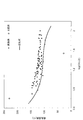
- the logarithm log (ion conductivity) of the ionic conductivity of the nonaqueous electrolyte is expressed as log (O / Li). It is the figure which plotted. In the figure, the horizontal axis indicates log (O / Li), and the vertical axis indicates log (ion conductivity) (S / cm).
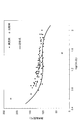
- FIG. 7 is a diagram in which the volatilization temperature of a nonaqueous electrolyte is plotted against log (O / Li) for the contents of Tables 1-2, 2-2, 3-2, and 4-2.
- FIG. 4 is a diagram in which the volatilization temperature of a nonvolatile electrolyte is plotted against log (O / Li) for the contents of Tables 1-2, 2-2, 3-2, and 4-2.
- the horizontal axis indicates log (O / Li)
- the vertical axis indicates volatilization temperature (° C.).
- a lithium ion secondary battery is an electrochemical device that stores or uses electric energy by inserting and extracting lithium ions into and from an electrode in an electrolyte. This is referred to by another name such as a lithium ion battery, a non-aqueous electrolyte secondary battery, and a non-aqueous electrolyte secondary battery, and any of the batteries is an object of the present invention.
- the technical idea of the present invention can be applied to a sodium ion secondary battery, a magnesium ion secondary battery, a calcium ion secondary battery, a zinc secondary battery, an aluminum ion secondary battery, and the like.
- the material may be selected alone, or may be selected in combination of two or more, within a range not inconsistent with the content disclosed in the present specification.
- a material other than the material group exemplified below may be selected within a range not inconsistent with the content disclosed in the present specification.
- FIG. 1 is a schematic sectional view illustrating the configuration of a secondary battery according to one embodiment of the present invention.
- FIG. 1 illustrates a stacked secondary battery.
- the secondary battery 1000 has a positive electrode 100, a negative electrode 200, a package 500, and an insulating layer 300.
- the outer package 500 contains the insulating layer 300, the positive electrode 100, and the negative electrode 200.
- the exterior body 500 may be formed of any material selected from a group of materials having corrosion resistance to a non-aqueous electrolyte, such as aluminum, stainless steel, and nickel-plated steel.
- the present invention can also be applied to a wound secondary battery.
- An electrode body 400 composed of a positive electrode 100, an insulating layer 300, and a negative electrode 200 is stacked in a secondary battery 1000.
- the insulating layer 300 has a nonvolatile electrolyte layer having a nonvolatile electrolyte as described later.
- the secondary battery 1000 may include the positive electrode 100, the negative electrode 200, and the non-volatile electrolyte layer having a non-volatile electrolyte described below formed between the positive electrode 100 and the negative electrode 200.
- the positive electrode 100 or the negative electrode 200 may be called an electrode.
- the positive electrode 100, the negative electrode 200, or the insulating layer 300 may be referred to as a secondary battery sheet.
- the positive electrode 100 has a positive electrode current collector 120 and a positive electrode mixture layer 110. Positive electrode mixture layers 110 are formed on both surfaces of positive electrode current collector 120.
- the negative electrode 200 has a negative electrode current collector 220 and a negative electrode mixture layer 210. Negative electrode mixture layers 210 are formed on both surfaces of negative electrode current collector 220.
- the positive electrode mixture layer 110 or the negative electrode mixture layer 210 may be referred to as an electrode mixture layer, and the positive electrode current collector 120 or the negative electrode current collector 220 may be referred to as an electrode current collector.
- the positive electrode current collector 120 has the positive electrode tab 130.
- the negative electrode current collector 220 has a negative electrode tab 230.
- the positive electrode tab 130 or the negative electrode tab 230 may be referred to as an electrode tab. No electrode mixture layer is formed on the electrode tab. However, an electrode mixture layer may be formed on the electrode tab within a range that does not adversely affect the performance of the secondary battery 1000.
- the positive electrode tab 130 and the negative electrode tab 230 protrude outside the exterior body 500. Then, the plurality of protruding positive electrode tabs 130 and the plurality of negative electrode tabs 230 are connected to each other by, for example, ultrasonic bonding, so that a parallel connection is formed in the secondary battery 1000.
- the present invention can be applied to a bipolar secondary battery in which an electric series connection is formed in the secondary battery 1000.
- the positive electrode mixture layer 110 has a positive electrode active material, a positive electrode conductive agent, and a positive electrode binder.
- the negative electrode mixture layer 210 includes a negative electrode active material, a negative electrode conductive agent, and a negative electrode binder.
- the positive electrode active material or the negative electrode active material may be referred to as an electrode active material
- the positive electrode conductive agent or the negative electrode conductive agent may be referred to as an electrode conductive agent
- the positive electrode binder or the negative electrode binder may be referred to as an electrode binder.
- the electrode conductive agent improves the conductivity of the electrode mixture layer.
- the electrode conductive agent is selected from a material group such as Ketjen black, acetylene black, and graphite.
- a particulate agent can be suitably used as the electrode conductive agent.
- the electrode binder binds an electrode active material and an electrode conductive agent in the electrode.
- the electrode binder is selected from a material group such as, for example, styrene-butadiene rubber, carboxymethylcellulose, polyvinylidene fluoride (PVDF), and the like.
- ⁇ Positive electrode active material> In the positive electrode active material having a noble potential, lithium ions are desorbed in a charging process, and lithium ions desorbed from the negative electrode active material in the negative electrode mixture layer 210 are inserted in a discharging process.
- a lithium composite oxide having a transition metal is desirable.
- x is the concentration of oxygen contained in the compound, and is an integer of 0 or more. Can be taken.).
- the element ratio may deviate from the stoichiometric composition.
- the positive electrode active material a material which is selected from the above-described material group and formed into particles can be suitably used.
- the positive electrode current collector 120 is selected from a material group such as an aluminum foil having a thickness of 1 to 100 ⁇ m and a perforated aluminum foil having a thickness of 10 to 100 ⁇ m and a hole diameter of 0.1 to 10 mm.
- ⁇ Negative electrode active material> In the negative electrode active material having a low potential, lithium ions are desorbed in a discharging process, and lithium ions desorbed from the positive electrode active material in the positive electrode mixture layer 110 are inserted in a charging process.
- the negative electrode active material includes, for example, a carbon-based material (graphite, easily graphitized carbon material, amorphous carbon material, organic crystal, activated carbon, and the like), silicon, a silicon-containing compound, and a conductive polymer material (polyacene, polyparaphenylene, Polyaniline, polyacetylene, etc.), lithium composite oxide (lithium titanate: Li 4 Ti 5 O 12 , Li 2 TiO 4, etc.), metallic lithium, at least one kind of metal alloying with lithium (aluminum, silicon, tin, etc.) ) And oxides thereof.
- the element ratio may deviate from the stoichiometric composition.
- As the negative electrode active material a material which is selected from the above-described material group and formed into a particle shape can be suitably used.
- the negative electrode current collector 220 is selected from a group of materials such as, for example, a copper foil having a thickness of 1 to 100 ⁇ m and a copper perforated foil having a thickness of 1 to 100 ⁇ m and a hole diameter of 0.1 to 10 mm.
- An electrode mixture layer is prepared by applying an electrode slurry obtained by mixing an electrode active material, an electrode conductive agent, an electrode binder and a solvent to an electrode current collector by a coating method such as a doctor blade method, a dipping method, or a spray method. You.
- the solvent is selected from a group of materials such as N-methylpyrrolidone (NMP) and water. Thereafter, the electrode mixture layer is dried to remove the solvent, and the electrode mixture layer is pressure-formed by a roll press to produce an electrode.
- a non-aqueous electrolyte is injected into the secondary battery 1000 from a vacant side or liquid injection hole of the outer package 500, and the pores of the electrode mixture layer are filled with the non-aqueous electrolyte.
- the particles such as the electrode active material and the electrode conductive agent in the electrode mixture layer function as the support particles without the need for the support particles contained in the nonvolatile electrolyte, and these particles hold the nonaqueous electrolyte. I do.
- a slurry is prepared by mixing a non-aqueous electrolyte, an electrode active material, an electrode conductive agent, and an electrode binder, and the adjusted slurry is subjected to electrode current collection. There is a method of applying together on the body.
- the thickness of the electrode mixture layer is desirably not less than the average particle size of the electrode active material.
- the thickness of the electrode mixture layer is set in this manner, the electron conductivity between adjacent electrode active materials can be improved. If the electrode active material powder contains coarse particles having an average particle size greater than the thickness of the electrode mixture layer, the coarse particles are removed in advance by sieving, airflow classification, etc. It is desirable that
- the insulating layer 300 serves as a medium for transmitting ions between the positive electrode 100 and the negative electrode 200.
- the insulating layer 300 also functions as an electron insulator, and prevents a short circuit between the positive electrode 100 and the negative electrode 200.
- the insulating layer 300 has a separator or a nonvolatile electrolyte layer.
- a separator and a nonvolatile electrolyte layer may be used in combination. In the present embodiment, it is preferable to use the nonvolatile electrolyte layer alone as the insulating layer 300 or to use the separator and the nonvolatile electrolyte layer together.
- a porous sheet can be used as the separator.
- the porous sheet is selected from, for example, a material group of cellulose, denatured cellulose (such as carboxymethylcellulose (CMC) and hydroxypropylcellulose (HPC)), and polyolefin (such as polypropylene (PP) and propylene copolymer). Those formed in an arbitrary shape can be used.
- separator for example, a separator formed by applying a mixture for forming a separator having separator particles, a separator binder and a solvent to the electrode mixture layer can be used.
- separator for example, a separator formed by applying a mixture for forming a separator to the porous sheet can be used.
- the separator particles are selected from a group of materials such as ⁇ -alumina (Al 2 O 3 ), silica (SiO 2 ), and zirconia (ZrO 2 ).
- the average particle diameter of the separator particles is preferably, for example, 1/100 to 1/2 of the thickness of the separator.
- the separator binder is selected from a material group such as polyethylene (PE), PP, polytetrafluoroethylene (PTFE), PVDF, styrene butadiene rubber (SBR), polyalginic acid, and polyacrylic acid.
- PE polyethylene
- PP polytetrafluoroethylene
- PVDF polytetrafluoroethylene
- SBR styrene butadiene rubber
- the separator is filled with the nonaqueous electrolyte by injecting the nonaqueous electrolyte into the secondary battery 1000 from one of the open sides or the injection hole of the outer package 500.
- the nonvolatile electrolyte layer has a nonvolatile electrolyte binder and a nonvolatile electrolyte.
- the non-volatile electrolyte has a carrier particle and a non-aqueous electrolyte.
- the non-volatile electrolyte has pores formed by the aggregate of the supporting particles, and the non-aqueous electrolyte is held therein. By holding the non-aqueous electrolyte in the nonvolatile electrolyte, the nonvolatile electrolyte allows lithium ions to permeate.
- a non-aqueous electrolyte When a non-aqueous electrolyte is used as the insulating layer 300 and the electrode mixture layer is filled with a non-aqueous electrolyte, it is not necessary to inject the non-aqueous electrolyte into the secondary battery 1000.
- a nonaqueous electrolyte may be injected into the secondary battery 1000 from one of the open sides or the injection hole of the outer package 500.
- Examples of the method for forming the nonvolatile electrolyte layer include a method in which the nonvolatile electrolyte powder is compression-molded into a pellet shape using a molding die or the like, a method in which a nonvolatile electrolyte binder is added to and mixed with the nonvolatile electrolyte powder, and a method in which a sheet is formed. is there.
- a method in which the powder of the nonvolatile electrolyte binder By adding and mixing the powder of the nonvolatile electrolyte binder to the nonvolatile electrolyte, a highly flexible sheet-like nonvolatile electrolyte layer can be produced.
- a solution of a binder obtained by dissolving a nonvolatile electrolyte binder in a dispersion solvent is added to and mixed with the nonvolatile electrolyte, the mixture is applied on a substrate such as an electrode, and the dispersion solvent is distilled off by drying. Then, a nonvolatile electrolyte layer may be formed.
- Nonvolatile electrolyte binder As the nonvolatile electrolyte binder, a fluorine-based resin is preferably used.
- the fluorine-based resin is selected from a group of materials such as PTFE and PVDF. These materials may be used alone or in combination. Among them, when PVDF is used, the adhesion between the insulating layer 300 and the electrode current collector is improved, so that the battery performance is improved.
- Nonvolatile electrolyte The non-aqueous electrolyte is carried or held by the carrier particles to form a nonvolatile electrolyte.
- a nonvolatile electrolyte solution and carrier particles are mixed at a specific volume ratio, an organic solvent such as methanol is added and mixed, and a nonvolatile electrolyte slurry is prepared.
- the slurry may be spread on a petri dish, and the organic solvent may be distilled off to obtain a nonvolatile electrolyte powder.
- the supporting particles are preferably insulating particles and insoluble in the non-aqueous electrolyte from the viewpoint of electrochemical stability.
- the carrier particles are selected from a material group such as SiO 2 particles, Al 2 O 3 particles, ceria (CeO 2 ) particles, oxide inorganic particles such as ZrO 2 particles, and solid electrolyte.
- oxide inorganic particles By using the oxide inorganic particles as the supporting particles, the non-aqueous electrolyte can be held at a high concentration in the nonvolatile electrolyte layer.
- the average particle size of the primary particles of the carrier particles is preferably, for example, 1 nm to 10 ⁇ m.
- the carrier particles can appropriately hold a sufficient amount of the non-aqueous electrolyte, thereby facilitating the formation of the nonvolatile electrolyte.
- the average particle size of the primary particles of the supported particles is in this range, the surface force between the supported particles is appropriately obtained, and the supported particles are less likely to aggregate with each other, so that the formation of the nonvolatile electrolyte is facilitated.
- the average particle size of the primary particles of the carrier particles is more preferably 1 to 50 nm, further preferably 1 to 10 nm.
- the average particle size of the primary particles of the supported particles can be measured using a TEM.
- the non-aqueous electrolyte is obtained by dissolving an electrolyte (for example, an electrolyte salt or a solvate electrolyte salt described later) in a non-aqueous solvent.
- the volatilization temperature of the non-aqueous electrolyte in this embodiment is 80 ° C. or higher.
- the volatilization temperature of the non-aqueous electrolyte in the present embodiment refers to a temperature at which the non-aqueous electrolyte is heated for a predetermined time and a predetermined amount of the non-aqueous electrolyte is reduced from the start of heating.
- the temperature of the secondary battery becomes 60 ° C. or higher. Therefore, depending on the components contained in the non-aqueous electrolyte, such as when the non-aqueous electrolyte contains a flammable organic solvent in a certain amount or more, the non-aqueous electrolyte may volatilize, and the safety of the secondary battery may decrease. .
- the volatilization temperature of the non-aqueous electrolyte to 80 ° C. or higher, even if the non-aqueous electrolyte contains a flammable organic solvent, the volatilization of the flammable organic solvent can be suppressed, and the secondary battery Safety can be improved.
- the volatilization temperature of the non-aqueous electrolyte is 80 ° C. or higher, the number of lithium ion carriers contained in the non-aqueous electrolyte and the interaction between the non-aqueous solvent in the non-aqueous electrolyte and lithium ions cause the non-aqueous electrolyte to The ionic conductivity changes. If the ionic conductivity of the non-aqueous electrolyte is low, the input / output characteristics of the secondary battery 1000 may deteriorate.
- log (O / Li) which is the logarithm of the ratio of the amount of oxygen contained in the non-aqueous electrolyte to the amount of lithium contained in the non-aqueous electrolyte
- Rate can be improved.
- the ionic conductivity of the non-aqueous electrolyte can be increased to 0.2 mS / cm (milli-Siemens per centimeter) or more.
- the volatilization temperature of the water electrolyte can be maintained at 80 ° C. or higher.
- the amount of lithium contained in the non-aqueous electrolyte and the amount of oxygen contained in the non-aqueous electrolyte were determined and managed by calculating the logarithm log (O / Li) of these ratios. It has been found that the ionic conductivity of the electrolytic solution can be suitably controlled. Regarding that the ionic conductivity of the non-aqueous electrolyte can be improved by defining log (O / Li) in a desired range, and that log (O / Li) is specifically set to 0.87 to 2.05. Will be described in the section of Examples.
- the log (O / Li) can be measured by quantifying the chemical composition and the mixing ratio by NMR or the like.
- log (O / Li) is desirably 0.87 to 1.93. This makes it possible to maintain the ionic conductivity of the non-aqueous electrolyte at 0.2 mS / cm or more and maintain the volatilization temperature of the non-aqueous electrolyte at 90 ° C. or more. Also, it is desirable that log (O / Li) is 1.10 to 1.84. Thereby, the volatilization temperature of the non-aqueous electrolyte can be kept at 95 ° C. or more while the ionic conductivity of the non-aqueous electrolyte is kept at 0.5 mS / cm or more.
- log (O / Li) is 1.30 to 1.71.
- the volatilization temperature of the non-aqueous electrolyte can be kept at 100 ° C. or more while the ionic conductivity of the non-aqueous electrolyte is kept at 1.1 mS / cm or more.
- the non-aqueous electrolyte has a non-aqueous solvent.
- the non-aqueous solvent has an organic solvent, an ionic liquid, or a mixture (complex) of an ether-based solvent and a solvated electrolyte salt exhibiting properties similar to the ionic liquid.
- An organic solvent, an ionic liquid or an ether solvent may be referred to as a main solvent.
- the nonaqueous electrolyte may use these materials alone or in combination.
- An ionic liquid is a compound that dissociates into a cation and an anion at room temperature and maintains a liquid state.
- the ionic liquid may be referred to as an ionic liquid, a low melting point molten salt or a room temperature molten salt.
- Non-aqueous solvent from the viewpoint of stability in the atmosphere and heat resistance in the secondary battery, low volatility, specifically, those having a vapor pressure of 150 Pa or less at room temperature are desirable, but are not limited thereto. Absent.
- a non-volatile solvent such as an ionic liquid or an ether-based solvent having properties similar to the ionic liquid as the non-aqueous electrolyte, volatilization of the non-aqueous electrolyte from the nonvolatile electrolyte layer can be suppressed.
- the content of the non-aqueous electrolyte in the nonvolatile electrolyte layer is not particularly limited, but is preferably 40 to 90 vol%. When the content of the non-aqueous electrolyte is in this range, the interface resistance between the electrode and the nonvolatile electrolyte layer hardly increases. Further, when the content of the non-aqueous electrolyte is in this range, the non-aqueous electrolyte hardly leaks from the nonvolatile electrolyte layer.
- the content of the non-aqueous electrolyte in the non-volatile electrolyte layer is desirably 50 to 80 vol%, and more desirably 60 to 80 vol%.
- the mixing mass ratio of the main solvent in the nonaqueous electrolyte is not particularly limited, the mass ratio of the main solvent to the total solvent in the nonaqueous electrolyte is 30 to 70% by mass from the viewpoint of battery stability and high-speed charge / discharge. Is preferably 40 to 60% by mass, and more preferably 45 to 55% by mass.
- Organic solvent examples include carbonates such as ethylene carbonate (EC), propylene carbonate (PC), butylene carbonate (BC), dimethyl carbonate (DMC), diethyl carbonate (DEC), and ethyl methyl carbonate (EMC), and ⁇ -butyrolactone. (GBL).
- EC ethylene carbonate
- PC propylene carbonate
- BC butylene carbonate
- DMC dimethyl carbonate
- DEC diethyl carbonate
- EMC ethyl methyl carbonate
- GBL ⁇ -butyrolactone
- the ionic liquid or an ether-based solvent having properties similar to the ionic liquid may have a low-viscosity organic solvent.
- the low-viscosity organic solvent lowers the viscosity of the non-aqueous electrolyte and improves the ionic conductivity.
- the internal resistance of the non-aqueous electrolyte is large, the internal resistance of the non-aqueous electrolyte can be reduced by adding a low-viscosity organic solvent to increase the ionic conductivity of the non-aqueous electrolyte.
- the low-viscosity organic solvent is preferably, but not limited to, a solvent having a viscosity of less than 140 Pa ⁇ s at 25 ° C. of a mixture of an ether solvent and a solvated electrolyte salt.
- the low-viscosity organic solvent is selected from a group of materials such as EC, PC, and GBL.
- Ionic liquids are composed of cations and anions. Ionic liquids are classified into imidazolium-based, pyrrolidinium-based, and the like, depending on the type of cation. Examples of the cation constituting the imidazolium-based ionic liquid include an alkyl imidazolium cation such as 1-butyl-3-methylimidazorium (BMI). Examples of the cations constituting the pyrrolidinium-based ionic liquid include alkylpyrrolidinium cations such as N-methyl-N-propylpyrrolidinium (Py13) and 1-butyl-1-methylpyrrolidinium.
- anion to be paired with these cations examples include bis (trifluoromethanesulfonyl) imide (TFSI), bis (fluorosulfonyl) imide, and tetrafluoroborate (BF 4 ).
- the non-aqueous electrolyte has an electrolyte salt. It is desirable that the electrolyte salt can be uniformly dispersed in the main solvent.
- the electrolyte salt a lithium salt composed of a lithium cation and the above-mentioned anion can be used.
- electrolyte salt examples include lithium bis (fluorosulfonyl) imide (LiFSI), lithium bis (trifluoromethanesulfonyl) imide (LiTFSI), lithium tetrafluoroborate (LiBF 4 ), lithium bisoxalate borate (LiBOB), and lithium It is selected from a group of materials such as triflate.
- LiFSI lithium bis (fluorosulfonyl) imide
- LiTFSI lithium bis (trifluoromethanesulfonyl) imide
- LiBF 4 lithium tetrafluoroborate
- LiBOB lithium bisoxalate borate
- It is selected from a group of materials such as triflate.
- the ether solvent forms a solvated ionic liquid with the solvated electrolyte salt.
- the ether solvent is, for example, symmetrical represented by glyme (RO (CH 2 CH 2 O) n -R ′ (R and R ′ are saturated hydrocarbons and n is an integer) exhibiting properties similar to an ionic liquid. Glycol diether).
- the glyme is preferably, for example, tetraglyme (tetraethylene dimethyl glycol, G4) or triglyme (triethylene glycol dimethyl ether, G3).
- Solvated electrolyte salt for example, LiFSI, LiTFSI, is selected from the group of materials such as LiBF 4.
- Example 1> ⁇ Preparation of nonvolatile electrolyte>
- Li salt 1 (A) was LiTFSI
- Li salt 2 (B) was not used
- solvent 1 (C) was G4
- solvent 2 (D) was PC
- solvent 3 (E) was not used.
- a non-aqueous electrolyte according to Example 1 was prepared. Note that, for the materials used, “LiTFSI”, “G4”, and the like correspond to those exemplified in the description of the embodiments for each material. "-" In Table 1-1 indicates that it is not used. These are the same for Tables 2-1, 3-1 and 4-1. Then, this mixed solvent and fumed silica nanoparticles having a particle diameter of 7 nm were weighed and mixed so as to have a volume ratio of 80:20 to obtain a powdery nonvolatile electrolyte.
- nonvolatile electrolyte layer ⁇ Preparation of nonvolatile electrolyte layer>
- the nonvolatile electrolyte and PTFE were each weighed so as to have a mass ratio of 95: 5, put into a mortar, and mixed uniformly.
- the mixture was set on a hydraulic press via a PTFE sheet and pressed at 39.2 MPa (400 kgf / cm 2 ). Further, the PTFE sheet was rolled by a roll press to have a thickness of 200 ⁇ m, and the mixture mass ratio of A, B, C, D, and E was 45.1: 0: 34.9: 20.0: 0 (Table 1). For No.
- log (O / Li) was derived from the amount of oxygen contained in the solvent in the non-aqueous electrolyte and the concentration of Li salt (amount of lithium).
- the nonvolatile electrolyte layer was sandwiched between two pieces of metal lithium foil punched out with a diameter of 16 mm and sealed in a CR2032 type coin cell.
- the impedance was measured at a voltage amplitude of 10 mV by a two-terminal method in a frequency range of 2 MHz to 10 mHz (2 MHz to 10 mHz).
- the point of intersection with the real axis on the high frequency side was defined as the resistance of the nonvolatile electrolyte layer, and the ionic conductivity (mS / cm) of the nonvolatile electrolyte layer was determined.
- log ⁇ ion conductivity (S / cm) ⁇ was derived from the ion conductivity.
- Example 1 was repeated except that the non-aqueous electrolyte and the like were as shown in Table 1-1, Table 2-1 and Table 3-1.
- Example 1 was repeated except that the nonaqueous electrolyte and the like were changed as shown in Table 4-1.
- FIGS. 2 to 4 show graphs of Table 1-2, Table 2-2, Table 3-2, and Table 4-2.
- the logarithm ( ⁇ ) of the ionic conductivity of the nonaqueous electrolyte as shown in FIG. 2 and the ratio of the amount of oxygen contained in the nonaqueous electrolyte to the amount of lithium contained in the nonaqueous electrolyte are shown in FIG.
- a logarithmic log (O / Li) relationship was derived.
- the relational expression between log ( ⁇ ) and log (O / Li) was derived as in the following expression (1).
- FIG. 2 shows the logarithm (ionic conductivity) of the ionic conductivity of the non-aqueous electrolyte as log (O / O / D) for the contents of Tables 1-2, 2-2, 3-2, and 4-2. It is the figure plotted with respect to Li).
- the curve shown in FIG. 2 is obtained by polynomial approximation of the minimum value of the ionic conductivity at each log (O / Li) among the obtained experimental values. It is larger than the value calculated from the curve.
- a composition smaller than this value is a region where the mixing ratio of the low-viscosity organic solvent is small, and as log (O / Li) approaches 1.55, that is, as the mixing ratio of the low-viscosity organic solvent increases, In addition, the viscosity of the non-aqueous electrolyte decreased, and the ionic conductivity of the non-aqueous electrolyte increased.
- FIG. 3 is a diagram in which the volatilization temperature of the non-aqueous electrolyte is plotted against log (O / Li) for the contents of Tables 1-2, 2-2, 3-2, and 4-2.
- the volatilization temperature of the non-aqueous electrolyte increased as the log (O / Li) became smaller, that is, as the mixing ratio of the low-viscosity organic solvent became smaller.
- the mixing ratio of the low-viscosity organic solvent decreases.
- Equation (2) represents the curve (approximate equation) shown in FIG. This equation is obtained by polynomial approximation of the minimum value of the volatilization temperature at each log (O / Li) among the obtained experimental values, and the volatilization temperature of various materials is calculated from this curve. It is larger than the value.
- FIG. 4 is a diagram in which the volatilization temperature of the nonvolatile electrolyte is plotted against log (O / Li) for the contents of Tables 1-2, 2-2, 3-2, and 4-2. Assuming that the volatilization temperature of the non-volatile electrolyte is T ', T' and log (O / Li) satisfy the following equation (3). Equation (3) represents the curve (approximation equation) in FIG.
- T ' - 101.24 ⁇ log ( O / Li) ⁇ 3 +423.56 ⁇ log (O / Li) ⁇ 2 -582.51 ⁇ log (O / Li) ⁇ + 365.7 ... (3)
- the volatilization temperature of the non-volatile electrolyte was lower than the volatilization temperature of the non-aqueous electrolyte, the temperature difference in each log (O / Li) derived from equations (1) and (2) was the largest. However, it was about 8 ° C.
- the ionic conductivity of the non-aqueous electrolyte is derived from the relationship between log ( ⁇ ) and log (O / Li) (formula (1)) and the relationship between T and log (O / Li) (formula (2)).
- the range of log (O / Li) at which both the non-aqueous electrolyte is 0.2 mS / cm or more and the volatilization temperature of the non-aqueous electrolyte is 80 ° C. or more is 0.87 to 2.05 (for the non-aqueous electrolyte in the nonvolatile electrolyte layer). In this case, it was 0.87 to 2.04).
- the range of log (O / Li) at which the ionic conductivity of the nonaqueous electrolyte is 0.2 mS / cm or more and the volatilization temperature of the nonaqueous electrolyte is 90 ° C or more is 0.87 to 1.93 ( In the case of the non-aqueous electrolyte in the nonvolatile electrolyte layer, the ratio was 0.87 to 1.95).
- the range of the log (O / Li) at which the ionic conductivity of the nonaqueous electrolyte is 0.5 mS / cm or more and the volatilization temperature of the nonaqueous electrolyte is 95 ° C or more is 1.10 to 1.84 (non-volatile). In the case of the non-aqueous electrolyte in the electrolyte layer, the ratio was 1.10 to 1.88).
- the range of log (O / Li) for satisfying both the ionic conductivity of the non-aqueous electrolyte of 1.1 mS / cm or more and the volatilization temperature of the non-aqueous electrolyte of 100 ° C. or more is 1.30 to 1.71 (non-volatile). In the case of the non-aqueous electrolyte in the electrolyte layer, it was found to be 1.30 to 1.78).
- the nonaqueous electrolyte according to the example satisfying the requirements of the present invention has an ionic conductivity of 0.2 mS / cm or more, the input / output characteristics are deteriorated when used in a secondary battery. Hard to do.
- the non-aqueous electrolyte according to the example satisfying the requirements of the present invention has a volatilization temperature of 80 ° C. or higher as described above, so even if the non-aqueous electrolyte contains a flammable organic solvent, The volatilization of the flammable organic solvent can be suppressed, and the safety of the secondary battery can be improved.
- the non-aqueous electrolyte, the nonvolatile electrolyte, and the secondary battery according to the present invention have been described in detail with reference to the embodiments and the examples.
- the gist of the present invention is not limited thereto, and various modifications may be made. included.
- the above-described embodiments have been described in detail for easy understanding of the present invention, and are not necessarily limited to those having all the configurations described above.
- a part of the configuration of one embodiment can be replaced with the configuration of another embodiment, and the configuration of one embodiment can be added to the configuration of another embodiment.
- REFERENCE SIGNS LIST 100 positive electrode 110 positive electrode mixture layer 120 positive electrode current collector 130 positive electrode tab 200 negative electrode 210 negative electrode mixture layer 220 negative electrode current collector 230 negative electrode tab 300 insulating layer 400 electrode body 500 exterior body 1000 secondary battery
Abstract
Provided is a nonaqueous electrolytic solution that improves safety of batteries. This nonaqueous electrolytic solution has a volatilization temperature not less than 80°C, and log(O/Li), which is the logarithm of the ratio of the amount of oxygen contained in the nonaqueous electrolytic solution with respect to the amount of lithium contained in the nonaqueous electrolytic solution, is 0.87-2.05.
Description
本発明は、非水電解液、不揮発性電解質、二次電池に関する。
The present invention relates to a non-aqueous electrolyte, a nonvolatile electrolyte, and a secondary battery.
非水電解液に関する技術として、特許文献1には以下の内容が開示されている。比誘電率が10以下および/または双極子モーメントが5D以下の特定有機溶媒を含むヘテロ元素含有有機溶媒と、リチウムをカチオンとし下記一般式(1)で表される化学構造をアニオンとする金属塩とを、モル比3~5で含む電解液、ならびに、粉末X線回折測定において1.10≦((003)面に由来するピークの積分強度I(003))/((104)面に由来するピークの積分強度I(104))<2.0を満足する、もしくは、一般式Lia(NixCoyMz)Ob(1.05≦a≦1.20、0.15≦x≦0.55、0.25≦y≦0.75、0.01≦z≦0.29、x+y+z=1、1.7≦b≦2.3、MはMn、Zr、Mg、Ti、Al、W、Si、Mo、Fe、B、Zn、Cuのうち少なくとも1つ)で表される、層状岩塩構造のリチウム金属複合酸化物を具備することを特徴とするリチウムイオン二次電池。
As a technique relating to a non-aqueous electrolyte, Patent Document 1 discloses the following content. A hetero element-containing organic solvent containing a specific organic solvent having a relative dielectric constant of 10 or less and / or a dipole moment of 5 D or less, and a metal salt having lithium as a cation and having a chemical structure represented by the following general formula (1) as an anion And a molar ratio of 3 to 5, and in the powder X-ray diffraction measurement, 1.10 ≦ (integrated intensity of peak derived from (003) plane I (003)) / derived from ((104) plane to satisfy the integrated intensity I (104)) <2.0 for the peak, or the general formula Li a (Ni x Co y M z) O b (1.05 ≦ a ≦ 1.20,0.15 ≦ x ≦ 0.55, 0.25 ≦ y ≦ 0.75, 0.01 ≦ z ≦ 0.29, x + y + z = 1, 1.7 ≦ b ≦ 2.3, M is Mn, Zr, Mg, Ti, Al , W, Si, Mo, Fe, B, Zn, Cu) A lithium ion secondary battery comprising a lithium metal composite oxide having a layered rock salt structure represented by the formula:
特許文献1では、電解液が揮発する温度に関する記載や示唆がないため、電池の使用条件によっては電解液が揮発し、電池の安全性が低下する可能性がある。
In Patent Document 1, there is no description or suggestion regarding the temperature at which the electrolytic solution volatilizes, so that the electrolytic solution may volatilize depending on the use conditions of the battery, and the safety of the battery may be reduced.
本発明は前記状況に鑑みてなされたものであり、電池の安全性を向上させる非水電解液、非水電解液を有する不揮発性電解質、二次電池を提供することを課題とする。
The present invention has been made in view of the above circumstances, and an object of the present invention is to provide a non-aqueous electrolyte, a non-aqueous electrolyte having a non-aqueous electrolyte, and a secondary battery which improve the safety of the battery.
前記課題を解決するため、本発明は、例えば以下の構成を有する。
揮発温度が80℃以上の非水電解液であり、非水電解液に含まれるリチウム量に対する非水電解液に含まれる酸素量の比の対数であるlog(O/Li)が0.87~2.05である非水電解液。 In order to solve the above problems, the present invention has, for example, the following configuration.
A non-aqueous electrolyte having a volatilization temperature of 80 ° C. or higher, and a log (O / Li), which is a logarithm of a ratio of an oxygen amount contained in the non-aqueous electrolyte to a lithium amount contained in the non-aqueous electrolyte, is 0.87 to 2.05 non-aqueous electrolyte.
本発明によれば、電池の安全性を向上させる非水電解液、非水電解液を有する不揮発性電解質、二次電池を提供できる。
前記した以外の課題、構成および効果は以下の実施形態の説明により明らかにされる。 ADVANTAGE OF THE INVENTION According to this invention, the nonaqueous electrolyte which improves the safety | security of a battery, the non-volatile electrolyte which has a nonaqueous electrolyte, and a secondary battery can be provided.
Problems, configurations, and effects other than those described above will be apparent from the following description of the embodiments.
以下、図面などを用いて、本発明の実施形態について説明する。以下の説明は本発明の内容の具体例を示すものであり、本発明がこれらの説明に限定されるものではなく、本明細書に開示される技術的思想の範囲内において当業者による様々な変更および修正が可能である。また、本発明を説明するための全図において、同一の機能を有するものは、同一の符号を付け、その繰り返しの説明は省略する場合がある。
本明細書に記載される「~」は、その前後に記載される数値を下限値および上限値として有する意味で使用する。本明細書に段階的に記載されている数値範囲において、一つの数値範囲で記載された上限値または下限値は、他の段階的に記載されている上限値または下限値に置き換えてもよい。本明細書に記載される数値範囲の上限値または下限値は、実施例中に示されている値に置き換えてもよい。 Hereinafter, embodiments of the present invention will be described with reference to the drawings and the like. The following description shows specific examples of the content of the present invention, and the present invention is not limited to these descriptions, and various modifications by those skilled in the art within the technical idea disclosed in the present specification. Changes and modifications are possible. In all the drawings for describing the present invention, components having the same function are denoted by the same reference numerals, and repeated description thereof may be omitted.
The term “to” described in this specification is used to mean that the numerical values described before and after it are used as a lower limit and an upper limit. In the numerical ranges described stepwise in this specification, the upper limit or lower limit described in one numerical range may be replaced with the upper limit or lower limit described in another step. The upper limit or lower limit of the numerical range described in this specification may be replaced with the value shown in the examples.
本明細書では、二次電池としてリチウムイオン二次電池を例にして説明する。リチウムイオン二次電池とは、電解質中における電極へのリチウムイオンの吸蔵・放出により、電気エネルギーを貯蔵または利用可能とする電気化学デバイスである。これは、リチウムイオン電池、非水電解質二次電池、非水電解液二次電池などの別の名称で呼ばれており、いずれの電池も本発明の対象である。本発明の技術的思想は、ナトリウムイオン二次電池、マグネシウムイオン二次電池、カルシウムイオン二次電池、亜鉛二次電池、アルミニウムイオン二次電池などに対しても適用できる。
で は In this specification, a lithium ion secondary battery will be described as an example of a secondary battery. A lithium ion secondary battery is an electrochemical device that stores or uses electric energy by inserting and extracting lithium ions into and from an electrode in an electrolyte. This is referred to by another name such as a lithium ion battery, a non-aqueous electrolyte secondary battery, and a non-aqueous electrolyte secondary battery, and any of the batteries is an object of the present invention. The technical idea of the present invention can be applied to a sodium ion secondary battery, a magnesium ion secondary battery, a calcium ion secondary battery, a zinc secondary battery, an aluminum ion secondary battery, and the like.
以下で例示している材料群から材料を選択する場合、本明細書で開示されている内容と矛盾しない範囲で、材料を単独で選択してもよく、複数組み合わせて選択してもよい、また、本明細書で開示されている内容と矛盾しない範囲で、以下で例示している材料群以外の材料を選択してもよい。
When selecting a material from the material group exemplified below, the material may be selected alone, or may be selected in combination of two or more, within a range not inconsistent with the content disclosed in the present specification. Alternatively, a material other than the material group exemplified below may be selected within a range not inconsistent with the content disclosed in the present specification.
図1は、本発明の一実施形態に係る二次電池の構成を説明する模式断面図である。図1は、積層型の二次電池を図示している。図1に示すように、二次電池1000は、正極100、負極200、外装体500および絶縁層300を有する。外装体500は、絶縁層300、正極100、負極200を収容する。外装体500は、アルミニウム、ステンレス鋼、ニッケルメッキ鋼など、非水電解液に対し耐食性のある材料群から選択して任意の形状に形成したものを用いることができる。本発明は、捲回型の二次電池にも適用できる。
FIG. 1 is a schematic sectional view illustrating the configuration of a secondary battery according to one embodiment of the present invention. FIG. 1 illustrates a stacked secondary battery. As shown in FIG. 1, the secondary battery 1000 has a positive electrode 100, a negative electrode 200, a package 500, and an insulating layer 300. The outer package 500 contains the insulating layer 300, the positive electrode 100, and the negative electrode 200. The exterior body 500 may be formed of any material selected from a group of materials having corrosion resistance to a non-aqueous electrolyte, such as aluminum, stainless steel, and nickel-plated steel. The present invention can also be applied to a wound secondary battery.
二次電池1000内で正極100、絶縁層300、負極200で構成される電極体400が積層されている。絶縁層300は、後記するように不揮発性電解質を有する不揮発性電解質層を有することが好ましい。つまり、本実施形態においては、二次電池1000は、正極100と、負極200と、正極100および負極200の間に形成された後記する不揮発性電解質を有する不揮発性電解質層と、を有することが好ましい。
正極100または負極200を電極と称する場合がある。正極100、負極200または絶縁層300を二次電池用シートと称する場合がある。 Anelectrode body 400 composed of a positive electrode 100, an insulating layer 300, and a negative electrode 200 is stacked in a secondary battery 1000. It is preferable that the insulating layer 300 has a nonvolatile electrolyte layer having a nonvolatile electrolyte as described later. That is, in the present embodiment, the secondary battery 1000 may include the positive electrode 100, the negative electrode 200, and the non-volatile electrolyte layer having a non-volatile electrolyte described below formed between the positive electrode 100 and the negative electrode 200. preferable.
Thepositive electrode 100 or the negative electrode 200 may be called an electrode. The positive electrode 100, the negative electrode 200, or the insulating layer 300 may be referred to as a secondary battery sheet.
正極100または負極200を電極と称する場合がある。正極100、負極200または絶縁層300を二次電池用シートと称する場合がある。 An
The
正極100は、正極集電体120および正極合剤層110を有する。正極集電体120の両面に正極合剤層110が形成されている。負極200は、負極集電体220および負極合剤層210を有する。負極集電体220の両面に負極合剤層210が形成されている。正極合剤層110または負極合剤層210を電極合剤層、正極集電体120または負極集電体220を電極集電体と称する場合がある。
The positive electrode 100 has a positive electrode current collector 120 and a positive electrode mixture layer 110. Positive electrode mixture layers 110 are formed on both surfaces of positive electrode current collector 120. The negative electrode 200 has a negative electrode current collector 220 and a negative electrode mixture layer 210. Negative electrode mixture layers 210 are formed on both surfaces of negative electrode current collector 220. The positive electrode mixture layer 110 or the negative electrode mixture layer 210 may be referred to as an electrode mixture layer, and the positive electrode current collector 120 or the negative electrode current collector 220 may be referred to as an electrode current collector.
正極集電体120は正極タブ130を有する。負極集電体220は負極タブ230を有する。正極タブ130または負極タブ230を電極タブと称する場合がある。電極タブには電極合剤層が形成されていない。ただし、二次電池1000の性能に悪影響を与えない範囲で電極タブに電極合剤層を形成してもよい。正極タブ130および負極タブ230は、外装体500の外部に突出している。そして、突出した複数の正極タブ130同士、複数の負極タブ230同士が、それぞれ例えば超音波接合などで接合されることで、二次電池1000内で並列接続が形成される。本発明は、二次電池1000中で電気的な直列接続を構成させたバイポーラ型の二次電池にも適用できる。
The positive electrode current collector 120 has the positive electrode tab 130. The negative electrode current collector 220 has a negative electrode tab 230. The positive electrode tab 130 or the negative electrode tab 230 may be referred to as an electrode tab. No electrode mixture layer is formed on the electrode tab. However, an electrode mixture layer may be formed on the electrode tab within a range that does not adversely affect the performance of the secondary battery 1000. The positive electrode tab 130 and the negative electrode tab 230 protrude outside the exterior body 500. Then, the plurality of protruding positive electrode tabs 130 and the plurality of negative electrode tabs 230 are connected to each other by, for example, ultrasonic bonding, so that a parallel connection is formed in the secondary battery 1000. The present invention can be applied to a bipolar secondary battery in which an electric series connection is formed in the secondary battery 1000.
正極合剤層110は、正極活物質、正極導電剤、正極バインダを有する。負極合剤層210は、負極活物質、負極導電剤、負極バインダを有する。正極活物質または負極活物質を電極活物質、正極導電剤または負極導電剤を電極導電剤、正極バインダまたは負極バインダを電極バインダと称する場合がある。
The positive electrode mixture layer 110 has a positive electrode active material, a positive electrode conductive agent, and a positive electrode binder. The negative electrode mixture layer 210 includes a negative electrode active material, a negative electrode conductive agent, and a negative electrode binder. The positive electrode active material or the negative electrode active material may be referred to as an electrode active material, the positive electrode conductive agent or the negative electrode conductive agent may be referred to as an electrode conductive agent, and the positive electrode binder or the negative electrode binder may be referred to as an electrode binder.
<電極導電剤>
電極導電剤は、電極合剤層の導電性を向上させる。電極導電剤は、例えば、ケッチェンブラック、アセチレンブラック、黒鉛などの材料群から選択される。電極導電剤は、粒子状のものを好適に用いることができる。 <Electrode conductive agent>
The electrode conductive agent improves the conductivity of the electrode mixture layer. The electrode conductive agent is selected from a material group such as Ketjen black, acetylene black, and graphite. As the electrode conductive agent, a particulate agent can be suitably used.
<電極バインダ>
電極バインダは、電極中の電極活物質や電極導電剤などを結着させる。電極バインダは、例えば、スチレン-ブタジエンゴム、カルボキシメチルセルロース、ポリフッ化ビニリデン(PVDF)などの材料群から選択される。 <Electrode binder>
The electrode binder binds an electrode active material and an electrode conductive agent in the electrode. The electrode binder is selected from a material group such as, for example, styrene-butadiene rubber, carboxymethylcellulose, polyvinylidene fluoride (PVDF), and the like.
<正極活物質>
貴な電位を示す正極活物質は、充電過程においてリチウムイオンが脱離し、放電過程において負極合剤層210中の負極活物質から脱離したリチウムイオンが挿入される。正極活物質としては、遷移金属を有するリチウム複合酸化物が望ましい。正極活物質としては、例えば、LiMO2、Li過剰組成のLi[LiM]O2、LiM2O4、LiMPO4、LiMVOx、LiMBO3、Li2MSiO4(ただし、M=Co、Ni、Mn、Fe、Cr、Zn、Ta、Al、Mg、Cu、Cd、Mo、Nb、W、Ruなどを少なくとも1種類以上有する。xは化合物に含まれる酸素濃度であり、0以上の任意の整数を取り得る。)などが挙げられる。元素比は前記定比組成からずれていてもよい。正極活物質は、前記した材料群から選択して粒子状に形成したものを好適に用いることができる。 <Positive electrode active material>
In the positive electrode active material having a noble potential, lithium ions are desorbed in a charging process, and lithium ions desorbed from the negative electrode active material in the negativeelectrode mixture layer 210 are inserted in a discharging process. As the positive electrode active material, a lithium composite oxide having a transition metal is desirable. As the positive electrode active material, for example, LiMO 2 , Li [LiM] O 2 having a Li excess composition, LiM 2 O 4 , LiMPO 4 , LiMVO x , LiMBO 3 , Li 2 MSiO 4 (where M = Co, Ni, Mn , Fe, Cr, Zn, Ta, Al, Mg, Cu, Cd, Mo, Nb, W, Ru, etc. x is the concentration of oxygen contained in the compound, and is an integer of 0 or more. Can be taken.). The element ratio may deviate from the stoichiometric composition. As the positive electrode active material, a material which is selected from the above-described material group and formed into particles can be suitably used.
貴な電位を示す正極活物質は、充電過程においてリチウムイオンが脱離し、放電過程において負極合剤層210中の負極活物質から脱離したリチウムイオンが挿入される。正極活物質としては、遷移金属を有するリチウム複合酸化物が望ましい。正極活物質としては、例えば、LiMO2、Li過剰組成のLi[LiM]O2、LiM2O4、LiMPO4、LiMVOx、LiMBO3、Li2MSiO4(ただし、M=Co、Ni、Mn、Fe、Cr、Zn、Ta、Al、Mg、Cu、Cd、Mo、Nb、W、Ruなどを少なくとも1種類以上有する。xは化合物に含まれる酸素濃度であり、0以上の任意の整数を取り得る。)などが挙げられる。元素比は前記定比組成からずれていてもよい。正極活物質は、前記した材料群から選択して粒子状に形成したものを好適に用いることができる。 <Positive electrode active material>
In the positive electrode active material having a noble potential, lithium ions are desorbed in a charging process, and lithium ions desorbed from the negative electrode active material in the negative
<正極集電体120>
正極集電体120は、例えば、厚さが1~100μmのアルミニウム箔、厚さが10~100μmで孔径0.1~10mmの孔を有するアルミニウム製穿孔箔などの材料群から選択される。 <Positive electrodecurrent collector 120>
The positive electrodecurrent collector 120 is selected from a material group such as an aluminum foil having a thickness of 1 to 100 μm and a perforated aluminum foil having a thickness of 10 to 100 μm and a hole diameter of 0.1 to 10 mm.
正極集電体120は、例えば、厚さが1~100μmのアルミニウム箔、厚さが10~100μmで孔径0.1~10mmの孔を有するアルミニウム製穿孔箔などの材料群から選択される。 <Positive electrode
The positive electrode
<負極活物質>
卑な電位を示す負極活物質は、放電過程においてリチウムイオンが脱離し、充電過程において正極合剤層110中の正極活物質から脱離したリチウムイオンが挿入される。負極活物質は、例えば、炭素系材料(黒鉛、易黒鉛化炭素材料、非晶質炭素材料、有機結晶、活性炭など)、シリコン、シリコン含有化合物、導電性高分子材料(ポリアセン、ポリパラフェニレン、ポリアニリン、ポリアセチレンなど)、リチウム複合酸化物(チタン酸リチウム:Li4Ti5O12やLi2TiO4など)、金属リチウム、リチウムと合金化する金属(アルミニウム、シリコン、スズなどを少なくとも1種類以上有する)やこれらの酸化物などの材料群から選択される。元素比は前記定比組成からずれていてもよい。負極活物質は、前記した材料群から選択して粒子状に形成したものを好適に用いることができる。 <Negative electrode active material>
In the negative electrode active material having a low potential, lithium ions are desorbed in a discharging process, and lithium ions desorbed from the positive electrode active material in the positiveelectrode mixture layer 110 are inserted in a charging process. The negative electrode active material includes, for example, a carbon-based material (graphite, easily graphitized carbon material, amorphous carbon material, organic crystal, activated carbon, and the like), silicon, a silicon-containing compound, and a conductive polymer material (polyacene, polyparaphenylene, Polyaniline, polyacetylene, etc.), lithium composite oxide (lithium titanate: Li 4 Ti 5 O 12 , Li 2 TiO 4, etc.), metallic lithium, at least one kind of metal alloying with lithium (aluminum, silicon, tin, etc.) ) And oxides thereof. The element ratio may deviate from the stoichiometric composition. As the negative electrode active material, a material which is selected from the above-described material group and formed into a particle shape can be suitably used.
卑な電位を示す負極活物質は、放電過程においてリチウムイオンが脱離し、充電過程において正極合剤層110中の正極活物質から脱離したリチウムイオンが挿入される。負極活物質は、例えば、炭素系材料(黒鉛、易黒鉛化炭素材料、非晶質炭素材料、有機結晶、活性炭など)、シリコン、シリコン含有化合物、導電性高分子材料(ポリアセン、ポリパラフェニレン、ポリアニリン、ポリアセチレンなど)、リチウム複合酸化物(チタン酸リチウム:Li4Ti5O12やLi2TiO4など)、金属リチウム、リチウムと合金化する金属(アルミニウム、シリコン、スズなどを少なくとも1種類以上有する)やこれらの酸化物などの材料群から選択される。元素比は前記定比組成からずれていてもよい。負極活物質は、前記した材料群から選択して粒子状に形成したものを好適に用いることができる。 <Negative electrode active material>
In the negative electrode active material having a low potential, lithium ions are desorbed in a discharging process, and lithium ions desorbed from the positive electrode active material in the positive
<負極集電体220>
負極集電体220は、例えば、厚さが1~100μmの銅箔、厚さが1~100μmで孔径0.1~10mmの孔を有する銅製穿孔箔などの材料群から選択される。 <Negative electrodecurrent collector 220>
The negative electrodecurrent collector 220 is selected from a group of materials such as, for example, a copper foil having a thickness of 1 to 100 μm and a copper perforated foil having a thickness of 1 to 100 μm and a hole diameter of 0.1 to 10 mm.
負極集電体220は、例えば、厚さが1~100μmの銅箔、厚さが1~100μmで孔径0.1~10mmの孔を有する銅製穿孔箔などの材料群から選択される。 <Negative electrode
The negative electrode
<電極>
電極活物質、電極導電剤、電極バインダおよび溶剤を混合した電極スラリーを、ドクターブレード法、ディッピング法、スプレー法などの塗工方法によって電極集電体へ付着させることで電極合剤層が作製される。溶剤は、例えば、N-メチルピロリドン(NMP)、水などの材料群から選択される。その後、溶剤を除去するために電極合剤層を乾燥し、ロールプレスによって電極合剤層を加圧成形することにより電極が作製される。 <Electrode>
An electrode mixture layer is prepared by applying an electrode slurry obtained by mixing an electrode active material, an electrode conductive agent, an electrode binder and a solvent to an electrode current collector by a coating method such as a doctor blade method, a dipping method, or a spray method. You. The solvent is selected from a group of materials such as N-methylpyrrolidone (NMP) and water. Thereafter, the electrode mixture layer is dried to remove the solvent, and the electrode mixture layer is pressure-formed by a roll press to produce an electrode.
電極が不揮発性電解質を有する場合、外装体500の空いている一辺や注液孔から二次電池1000に非水電解液を注入し、電極合剤層の細孔に非水電解液を充填させてもよい。これにより、不揮発性電解質に含まれる担持粒子を要せず、電極合剤層中の電極活物質や電極導電剤などの粒子が担持粒子として機能して、それらの粒子が非水電解液を保持する。電極合剤層の細孔に非水電解液を充填する別の方法として、非水電解液、電極活物質、電極導電剤、電極バインダを混合したスラリーを調製し、調整したスラリーを電極集電体上に一緒に塗布する方法などがある。
When the electrode has a non-volatile electrolyte, a non-aqueous electrolyte is injected into the secondary battery 1000 from a vacant side or liquid injection hole of the outer package 500, and the pores of the electrode mixture layer are filled with the non-aqueous electrolyte. You may. As a result, the particles such as the electrode active material and the electrode conductive agent in the electrode mixture layer function as the support particles without the need for the support particles contained in the nonvolatile electrolyte, and these particles hold the nonaqueous electrolyte. I do. As another method of filling the pores of the electrode mixture layer with the non-aqueous electrolyte, a slurry is prepared by mixing a non-aqueous electrolyte, an electrode active material, an electrode conductive agent, and an electrode binder, and the adjusted slurry is subjected to electrode current collection. There is a method of applying together on the body.
電極合剤層の厚さは、電極活物質の平均粒径以上とすることが望ましい。電極合剤層の厚さをこのようにすると、隣接する電極活物質間の電子伝導性を良好なものとできる。電極活物質粉末中に電極合剤層の厚さ以上の平均粒径を有する粗粒がある場合、ふるい分級、風流分級などにより粗粒を予め除去し、電極合剤層の厚さ以下の粒子とすることが望ましい。
The thickness of the electrode mixture layer is desirably not less than the average particle size of the electrode active material. When the thickness of the electrode mixture layer is set in this manner, the electron conductivity between adjacent electrode active materials can be improved. If the electrode active material powder contains coarse particles having an average particle size greater than the thickness of the electrode mixture layer, the coarse particles are removed in advance by sieving, airflow classification, etc. It is desirable that
<絶縁層300>
絶縁層300は、正極100と負極200の間にイオンを伝達させる媒体となる。絶縁層300は電子の絶縁体としても働き、正極100と負極200の短絡を防止する。絶縁層300は、セパレータまたは不揮発性電解質層を有する。絶縁層300として、セパレータと不揮発性電解質層とを併用してもよい。なお、本実施形態においては、絶縁層300として、不揮発性電解質層を単体で使用するか、セパレータと不揮発性電解質層とを併用することが好ましい。 <Insulatinglayer 300>
The insulatinglayer 300 serves as a medium for transmitting ions between the positive electrode 100 and the negative electrode 200. The insulating layer 300 also functions as an electron insulator, and prevents a short circuit between the positive electrode 100 and the negative electrode 200. The insulating layer 300 has a separator or a nonvolatile electrolyte layer. As the insulating layer 300, a separator and a nonvolatile electrolyte layer may be used in combination. In the present embodiment, it is preferable to use the nonvolatile electrolyte layer alone as the insulating layer 300 or to use the separator and the nonvolatile electrolyte layer together.
絶縁層300は、正極100と負極200の間にイオンを伝達させる媒体となる。絶縁層300は電子の絶縁体としても働き、正極100と負極200の短絡を防止する。絶縁層300は、セパレータまたは不揮発性電解質層を有する。絶縁層300として、セパレータと不揮発性電解質層とを併用してもよい。なお、本実施形態においては、絶縁層300として、不揮発性電解質層を単体で使用するか、セパレータと不揮発性電解質層とを併用することが好ましい。 <Insulating
The insulating
<セパレータ>
セパレータとして、多孔質シートを用いることができる。多孔質シートは、例えば、セルロース、セルロースの変成体(カルボキシメチルセルロース(CMC)、ヒドロキシプロピルセルロース(HPC)など)、ポリオレフィン(ポリプロピレン(PP)、プロピレンの共重合体など)の材料群から選択して任意の形状に形成したものを用いることができる。セパレータを正極100または負極200より大面積にすることで、正極100と負極200の短絡を防止できる。 <Separator>
A porous sheet can be used as the separator. The porous sheet is selected from, for example, a material group of cellulose, denatured cellulose (such as carboxymethylcellulose (CMC) and hydroxypropylcellulose (HPC)), and polyolefin (such as polypropylene (PP) and propylene copolymer). Those formed in an arbitrary shape can be used. By making the separator larger in area than thepositive electrode 100 or the negative electrode 200, short circuit between the positive electrode 100 and the negative electrode 200 can be prevented.
セパレータとして、多孔質シートを用いることができる。多孔質シートは、例えば、セルロース、セルロースの変成体(カルボキシメチルセルロース(CMC)、ヒドロキシプロピルセルロース(HPC)など)、ポリオレフィン(ポリプロピレン(PP)、プロピレンの共重合体など)の材料群から選択して任意の形状に形成したものを用いることができる。セパレータを正極100または負極200より大面積にすることで、正極100と負極200の短絡を防止できる。 <Separator>
A porous sheet can be used as the separator. The porous sheet is selected from, for example, a material group of cellulose, denatured cellulose (such as carboxymethylcellulose (CMC) and hydroxypropylcellulose (HPC)), and polyolefin (such as polypropylene (PP) and propylene copolymer). Those formed in an arbitrary shape can be used. By making the separator larger in area than the
セパレータは、例えば、セパレータ粒子、セパレータバインダおよび溶剤を有するセパレータ形成用混合物を電極合剤層に塗布して形成したものを用いることができる。また、セパレータは、例えば、セパレータ形成用混合物を前記の多孔質シートに塗布して形成したものを用いることができる。
As the separator, for example, a separator formed by applying a mixture for forming a separator having separator particles, a separator binder and a solvent to the electrode mixture layer can be used. As the separator, for example, a separator formed by applying a mixture for forming a separator to the porous sheet can be used.
セパレータ粒子は、例えば、γ-アルミナ(Al2O3)、シリカ(SiO2)、ジルコニア(ZrO2)などの材料群から選択される。セパレータ粒子の平均粒子径は、例えば、セパレータの厚さの1/100~1/2とすることが望ましい。
The separator particles are selected from a group of materials such as γ-alumina (Al 2 O 3 ), silica (SiO 2 ), and zirconia (ZrO 2 ). The average particle diameter of the separator particles is preferably, for example, 1/100 to 1/2 of the thickness of the separator.
セパレータバインダは、例えば、ポリエチレン(PE)、PP、ポリテトラフルオロエチレン(PTFE)、PVDF、スチレンブタジエンゴム(SBR)、ポリアルギン酸、ポリアクリル酸などの材料群から選択される。
The separator binder is selected from a material group such as polyethylene (PE), PP, polytetrafluoroethylene (PTFE), PVDF, styrene butadiene rubber (SBR), polyalginic acid, and polyacrylic acid.
絶縁層300としてセパレータを用いる場合、外装体500の空いている一辺や注液孔から二次電池1000に非水電解液を注入することで、セパレータ中に非水電解液が充填される。
In the case where a separator is used as the insulating layer 300, the separator is filled with the nonaqueous electrolyte by injecting the nonaqueous electrolyte into the secondary battery 1000 from one of the open sides or the injection hole of the outer package 500.
<不揮発性電解質層>
不揮発性電解質層は、不揮発性電解質バインダおよび不揮発性電解質を有する。不揮発性電解質は、担持粒子および非水電解液を有する。
不揮発性電解質は、担持粒子の集合体によって形成される細孔を有し、その中に非水電解液が保持されている。不揮発性電解質中に非水電解液が保持されることによって、不揮発性電解質はリチウムイオンを透過させる。絶縁層300として不揮発性電解質層を用い、電極合剤層に非水電解液が充填される場合、二次電池1000への非水電解液の注入は不要になる。絶縁層300がセパレータを有する場合など、外装体500の空いている一辺や注液孔から二次電池1000へ非水電解液を注入してもよい。 <Nonvolatile electrolyte layer>
The nonvolatile electrolyte layer has a nonvolatile electrolyte binder and a nonvolatile electrolyte. The non-volatile electrolyte has a carrier particle and a non-aqueous electrolyte.
The non-volatile electrolyte has pores formed by the aggregate of the supporting particles, and the non-aqueous electrolyte is held therein. By holding the non-aqueous electrolyte in the nonvolatile electrolyte, the nonvolatile electrolyte allows lithium ions to permeate. When a non-aqueous electrolyte is used as the insulatinglayer 300 and the electrode mixture layer is filled with a non-aqueous electrolyte, it is not necessary to inject the non-aqueous electrolyte into the secondary battery 1000. For example, when the insulating layer 300 has a separator, a nonaqueous electrolyte may be injected into the secondary battery 1000 from one of the open sides or the injection hole of the outer package 500.
不揮発性電解質層は、不揮発性電解質バインダおよび不揮発性電解質を有する。不揮発性電解質は、担持粒子および非水電解液を有する。
不揮発性電解質は、担持粒子の集合体によって形成される細孔を有し、その中に非水電解液が保持されている。不揮発性電解質中に非水電解液が保持されることによって、不揮発性電解質はリチウムイオンを透過させる。絶縁層300として不揮発性電解質層を用い、電極合剤層に非水電解液が充填される場合、二次電池1000への非水電解液の注入は不要になる。絶縁層300がセパレータを有する場合など、外装体500の空いている一辺や注液孔から二次電池1000へ非水電解液を注入してもよい。 <Nonvolatile electrolyte layer>
The nonvolatile electrolyte layer has a nonvolatile electrolyte binder and a nonvolatile electrolyte. The non-volatile electrolyte has a carrier particle and a non-aqueous electrolyte.
The non-volatile electrolyte has pores formed by the aggregate of the supporting particles, and the non-aqueous electrolyte is held therein. By holding the non-aqueous electrolyte in the nonvolatile electrolyte, the nonvolatile electrolyte allows lithium ions to permeate. When a non-aqueous electrolyte is used as the insulating
不揮発性電解質層の作製方法として、不揮発性電解質の粉末を成型ダイスなどでペレット状に圧縮成型する方法や、不揮発性電解質バインダを不揮発性電解質の粉末に添加・混合し、シート化する方法などがある。不揮発性電解質に不揮発性電解質バインダの粉末を添加・混合することにより、柔軟性の高いシート状の不揮発性電解質層を作製できる。また、不揮発性電解質に、分散溶媒に不揮発性電解質バインダを溶解させた結着剤の溶液を添加・混合し、電極などの基材上に混合物を塗布し、乾燥により分散溶媒を留去することで、不揮発性電解質層を作製してもよい。
Examples of the method for forming the nonvolatile electrolyte layer include a method in which the nonvolatile electrolyte powder is compression-molded into a pellet shape using a molding die or the like, a method in which a nonvolatile electrolyte binder is added to and mixed with the nonvolatile electrolyte powder, and a method in which a sheet is formed. is there. By adding and mixing the powder of the nonvolatile electrolyte binder to the nonvolatile electrolyte, a highly flexible sheet-like nonvolatile electrolyte layer can be produced. In addition, a solution of a binder obtained by dissolving a nonvolatile electrolyte binder in a dispersion solvent is added to and mixed with the nonvolatile electrolyte, the mixture is applied on a substrate such as an electrode, and the dispersion solvent is distilled off by drying. Then, a nonvolatile electrolyte layer may be formed.
<不揮発性電解質バインダ>
不揮発性電解質バインダは、フッ素系の樹脂が好適に用いられる。フッ素系の樹脂としては、例えば、PTFE、PVDFなどの材料群から選択される。これらの材料を単独または複数組み合わせて使用してもよい。これらの中でもPVDFを用いると、絶縁層300と電極集電体の密着性が向上するため、電池性能が向上する。 <Nonvolatile electrolyte binder>
As the nonvolatile electrolyte binder, a fluorine-based resin is preferably used. The fluorine-based resin is selected from a group of materials such as PTFE and PVDF. These materials may be used alone or in combination. Among them, when PVDF is used, the adhesion between the insulatinglayer 300 and the electrode current collector is improved, so that the battery performance is improved.
不揮発性電解質バインダは、フッ素系の樹脂が好適に用いられる。フッ素系の樹脂としては、例えば、PTFE、PVDFなどの材料群から選択される。これらの材料を単独または複数組み合わせて使用してもよい。これらの中でもPVDFを用いると、絶縁層300と電極集電体の密着性が向上するため、電池性能が向上する。 <Nonvolatile electrolyte binder>
As the nonvolatile electrolyte binder, a fluorine-based resin is preferably used. The fluorine-based resin is selected from a group of materials such as PTFE and PVDF. These materials may be used alone or in combination. Among them, when PVDF is used, the adhesion between the insulating
<不揮発性電解質>
非水電解液が担持粒子に担持または保持されることにより不揮発性電解質が構成される。不揮発性電解質の作製方法としては、例えば、非水電解液と担持粒子とを特定の体積比率で混合し、メタノールなどの有機溶媒を添加して混合し、不揮発性電解質のスラリーを調合した後、スラリーをシャーレに広げ、有機溶媒を留去して不揮発性電解質の粉末を得ることなどが挙げられる。 <Nonvolatile electrolyte>
The non-aqueous electrolyte is carried or held by the carrier particles to form a nonvolatile electrolyte. As a method for producing a nonvolatile electrolyte, for example, a non-aqueous electrolyte solution and carrier particles are mixed at a specific volume ratio, an organic solvent such as methanol is added and mixed, and a nonvolatile electrolyte slurry is prepared. The slurry may be spread on a petri dish, and the organic solvent may be distilled off to obtain a nonvolatile electrolyte powder.
<担持粒子>
担持粒子としては、電気化学的安定性の観点から、絶縁性粒子であり非水電解液に不溶であることが好ましい。担持粒子は、例えば、SiO2粒子、Al2O3粒子、セリア(CeO2)粒子、ZrO2粒子などの酸化物無機粒子、固体電解質などの材料群から選択される。担持粒子として酸化物無機粒子を用いることにより、不揮発性電解質層内で非水電解液を高濃度で保持できる。 <Supported particles>
The supporting particles are preferably insulating particles and insoluble in the non-aqueous electrolyte from the viewpoint of electrochemical stability. The carrier particles are selected from a material group such as SiO 2 particles, Al 2 O 3 particles, ceria (CeO 2 ) particles, oxide inorganic particles such as ZrO 2 particles, and solid electrolyte. By using the oxide inorganic particles as the supporting particles, the non-aqueous electrolyte can be held at a high concentration in the nonvolatile electrolyte layer.
非水電解液の保持量は担持粒子の比表面積に比例すると考えられるため、担持粒子の一次粒子の平均粒径は、例えば、1nm~10μmが好ましい。担持粒子の一次粒子の平均粒径がこの範囲にあると、担持粒子が十分な量の非水電解液を適切に保持できるので、不揮発性電解質の形成が容易になる。また、担持粒子の一次粒子の平均粒径がこの範囲にあると、担持粒子間の表面間力が適切に得られ担持粒子同士が凝集しにくくなるので、不揮発性電解質の形成が容易となる。担持粒子の一次粒子の平均粒径は、1~50nmがより好ましく、1~10nmがさらに好ましい。担持粒子の一次粒子の平均粒径は、TEMを用いて測定できる。
た め Since the holding amount of the nonaqueous electrolyte is considered to be proportional to the specific surface area of the carrier particles, the average particle size of the primary particles of the carrier particles is preferably, for example, 1 nm to 10 μm. When the average particle size of the primary particles of the carrier particles is in this range, the carrier particles can appropriately hold a sufficient amount of the non-aqueous electrolyte, thereby facilitating the formation of the nonvolatile electrolyte. When the average particle size of the primary particles of the supported particles is in this range, the surface force between the supported particles is appropriately obtained, and the supported particles are less likely to aggregate with each other, so that the formation of the nonvolatile electrolyte is facilitated. The average particle size of the primary particles of the carrier particles is more preferably 1 to 50 nm, further preferably 1 to 10 nm. The average particle size of the primary particles of the supported particles can be measured using a TEM.
<非水電解液>
非水電解液は、非水溶媒に電解質(例えば、後記する電解質塩や溶媒和電解質塩など)を溶かしたものである。本実施形態における非水電解液の揮発温度は80℃以上とする。本実施形態における非水電解液の揮発温度とは、非水電解液を所定時間加熱して、加熱開始時より所定量の非水電解液が減少した温度をいう。非水電解液を有する二次電池の充放電の繰り返し動作や、二次電池が設置されている場所によっては二次電池が60℃以上の高温となる。そのため、非水電解液に可燃性の有機溶媒が一定量以上含まれる場合など、非水電解液の含有成分によっては非水電解液が揮発し、二次電池の安全性が低下する場合がある。そこで、非水電解液の揮発温度を80℃以上にすることにより、非水電解液が可燃性の有機溶媒を含有していても、当該可燃性の有機溶媒の揮発を抑制でき、二次電池の安全性を向上できる。 <Non-aqueous electrolyte>
The non-aqueous electrolyte is obtained by dissolving an electrolyte (for example, an electrolyte salt or a solvate electrolyte salt described later) in a non-aqueous solvent. The volatilization temperature of the non-aqueous electrolyte in this embodiment is 80 ° C. or higher. The volatilization temperature of the non-aqueous electrolyte in the present embodiment refers to a temperature at which the non-aqueous electrolyte is heated for a predetermined time and a predetermined amount of the non-aqueous electrolyte is reduced from the start of heating. Depending on the repetitive operation of charging and discharging of the secondary battery having the non-aqueous electrolyte and the place where the secondary battery is installed, the temperature of the secondary battery becomes 60 ° C. or higher. Therefore, depending on the components contained in the non-aqueous electrolyte, such as when the non-aqueous electrolyte contains a flammable organic solvent in a certain amount or more, the non-aqueous electrolyte may volatilize, and the safety of the secondary battery may decrease. . Thus, by setting the volatilization temperature of the non-aqueous electrolyte to 80 ° C. or higher, even if the non-aqueous electrolyte contains a flammable organic solvent, the volatilization of the flammable organic solvent can be suppressed, and the secondary battery Safety can be improved.
非水電解液の揮発温度を80℃以上とした場合、非水電解液に含まれるリチウムイオンキャリア数や非水電解液中の非水溶媒とリチウムイオンとの相互作用により、非水電解液のイオン伝導率が変化する。非水電解液のイオン伝導率が低いと、二次電池1000の入出力特性が低下する場合がある。そこで、非水電解液に含まれるリチウム量に対する非水電解液に含まれる酸素量の比の対数であるlog(O/Li)を所望の範囲に規定することで、非水電解液のイオン伝導率を向上できる。具体的には、log(O/Li)を0.87~2.05とすることで、非水電解液のイオン伝導率を0.2mS/cm(ミリジーメンス毎センチメートル)以上にしつつ、非水電解液の揮発温度を80℃以上に保つことができる。なお、種々検討した結果、非水電解液に含まれるリチウム量と、非水電解液に含まれる酸素量とは、これらの比の対数log(O/Li)を求めて管理することで非水電解液のイオン伝導率を好適に制御できることを見出したものである。log(O/Li)を所望の範囲に規定することで非水電解液のイオン伝導率を向上できることや、log(O/Li)を具体的に0.87~2.05としたことなどについては、実施例の項目で説明する。log(O/Li)が小さいと、非水電解液に含まれるリチウムイオンキャリアが減少するため、非水電解液のイオン伝導率が低下する。一方、log(O/Li)が大きいと、非水電解液中の非水溶媒とリチウムイオンとの相互作用が強くなり、リチウムイオンが動きにくくなるため、非水電解液のイオン伝導率が低下する。log(O/Li)は、NMRなどにより化学組成や混合比を定量化することで計測できる。
When the volatilization temperature of the non-aqueous electrolyte is 80 ° C. or higher, the number of lithium ion carriers contained in the non-aqueous electrolyte and the interaction between the non-aqueous solvent in the non-aqueous electrolyte and lithium ions cause the non-aqueous electrolyte to The ionic conductivity changes. If the ionic conductivity of the non-aqueous electrolyte is low, the input / output characteristics of the secondary battery 1000 may deteriorate. Therefore, by defining log (O / Li), which is the logarithm of the ratio of the amount of oxygen contained in the non-aqueous electrolyte to the amount of lithium contained in the non-aqueous electrolyte, within a desired range, the ionic conductivity of the non-aqueous electrolyte is regulated. Rate can be improved. Specifically, by setting the log (O / Li) to 0.87 to 2.05, the ionic conductivity of the non-aqueous electrolyte can be increased to 0.2 mS / cm (milli-Siemens per centimeter) or more. The volatilization temperature of the water electrolyte can be maintained at 80 ° C. or higher. As a result of various studies, the amount of lithium contained in the non-aqueous electrolyte and the amount of oxygen contained in the non-aqueous electrolyte were determined and managed by calculating the logarithm log (O / Li) of these ratios. It has been found that the ionic conductivity of the electrolytic solution can be suitably controlled. Regarding that the ionic conductivity of the non-aqueous electrolyte can be improved by defining log (O / Li) in a desired range, and that log (O / Li) is specifically set to 0.87 to 2.05. Will be described in the section of Examples. When the log (O / Li) is small, the amount of lithium ion carriers contained in the non-aqueous electrolyte decreases, so that the ionic conductivity of the non-aqueous electrolyte decreases. On the other hand, when log (O / Li) is large, the interaction between the non-aqueous solvent in the non-aqueous electrolyte and the lithium ions becomes strong, and the lithium ions become difficult to move, so that the ionic conductivity of the non-aqueous electrolyte decreases. I do. The log (O / Li) can be measured by quantifying the chemical composition and the mixing ratio by NMR or the like.
本実施形態においては、log(O/Li)は0.87~1.93であることが望ましい。これにより、非水電解液のイオン伝導率を0.2mS/cm以上にしつつ、非水電解液の揮発温度を90℃以上に保つことができる。また、log(O/Li)は1.10~1.84であることが望ましい。これにより、非水電解液のイオン伝導率を0.5mS/cm以上にしつつ、非水電解液の揮発温度を95℃以上に保つことができる。また、log(O/Li)は1.30~1.71であることが望ましい。これにより、非水電解液のイオン伝導率を1.1mS/cm以上にしつつ、非水電解液の揮発温度を100℃以上に保つことができる。
に お い て In the present embodiment, log (O / Li) is desirably 0.87 to 1.93. This makes it possible to maintain the ionic conductivity of the non-aqueous electrolyte at 0.2 mS / cm or more and maintain the volatilization temperature of the non-aqueous electrolyte at 90 ° C. or more. Also, it is desirable that log (O / Li) is 1.10 to 1.84. Thereby, the volatilization temperature of the non-aqueous electrolyte can be kept at 95 ° C. or more while the ionic conductivity of the non-aqueous electrolyte is kept at 0.5 mS / cm or more. Also, it is desirable that log (O / Li) is 1.30 to 1.71. Thereby, the volatilization temperature of the non-aqueous electrolyte can be kept at 100 ° C. or more while the ionic conductivity of the non-aqueous electrolyte is kept at 1.1 mS / cm or more.
<非水電解液の構成材料>
非水電解液は、非水溶媒を有する。非水溶媒は、有機溶媒、イオン液体またはイオン液体に類似の性質を示すエーテル系溶媒および溶媒和電解質塩の混合物(錯体)を有する。有機溶媒、イオン液体またはエーテル系溶媒を主溶媒と称する場合がある。非水電解液は、これらの材料を単独または複数組み合わせて使用してもよい。
イオン液体とは、常温でカチオンとアニオンに解離する化合物であって、液体の状態を保持するものである。イオン液体は、イオン性液体、低融点溶融塩あるいは常温溶融塩と称されることがある。
非水溶媒は、大気中での安定性や二次電池内での耐熱性の観点から、低揮発性、具体的には室温における蒸気圧が150Pa以下であるものが望ましいが、これに限られない。
非水電解液にイオン液体またはイオン液体に類似の性質を示すエーテル系溶媒等の難揮発性の溶媒を用いることで、不揮発性電解質層からの非水電解液の揮発を抑制できる。 <Constituent materials of non-aqueous electrolyte>
The non-aqueous electrolyte has a non-aqueous solvent. The non-aqueous solvent has an organic solvent, an ionic liquid, or a mixture (complex) of an ether-based solvent and a solvated electrolyte salt exhibiting properties similar to the ionic liquid. An organic solvent, an ionic liquid or an ether solvent may be referred to as a main solvent. The nonaqueous electrolyte may use these materials alone or in combination.
An ionic liquid is a compound that dissociates into a cation and an anion at room temperature and maintains a liquid state. The ionic liquid may be referred to as an ionic liquid, a low melting point molten salt or a room temperature molten salt.
Non-aqueous solvent, from the viewpoint of stability in the atmosphere and heat resistance in the secondary battery, low volatility, specifically, those having a vapor pressure of 150 Pa or less at room temperature are desirable, but are not limited thereto. Absent.
By using a non-volatile solvent such as an ionic liquid or an ether-based solvent having properties similar to the ionic liquid as the non-aqueous electrolyte, volatilization of the non-aqueous electrolyte from the nonvolatile electrolyte layer can be suppressed.
不揮発性電解質層中の非水電解液の含有量は特には限定されないが、40~90vol%であることが望ましい。非水電解液の含有量がこの範囲であると、電極と不揮発性電解質層との界面抵抗が増加しにくい。また、非水電解液の含有量がこの範囲であると、不揮発性電解質層から非水電解液が漏れ出しにくい。不揮発性電解質層がシート状に形成されている場合、不揮発性電解質層中の非水電解液の含有量は50~80vol%であることが望ましく、60~80vol%であることがより望ましい。
非 The content of the non-aqueous electrolyte in the nonvolatile electrolyte layer is not particularly limited, but is preferably 40 to 90 vol%. When the content of the non-aqueous electrolyte is in this range, the interface resistance between the electrode and the nonvolatile electrolyte layer hardly increases. Further, when the content of the non-aqueous electrolyte is in this range, the non-aqueous electrolyte hardly leaks from the nonvolatile electrolyte layer. When the non-volatile electrolyte layer is formed in a sheet shape, the content of the non-aqueous electrolyte in the non-volatile electrolyte layer is desirably 50 to 80 vol%, and more desirably 60 to 80 vol%.
非水電解液における主溶媒の混合質量比率は特には限定されないが、電池安定性および高速充放電の観点から非水電解液中の溶媒の総和に占める主溶媒の質量比率は30~70質量%であることが望ましく、40~60質量%であることがより望ましく、45~55質量%であることがさらに望ましい。
Although the mixing mass ratio of the main solvent in the nonaqueous electrolyte is not particularly limited, the mass ratio of the main solvent to the total solvent in the nonaqueous electrolyte is 30 to 70% by mass from the viewpoint of battery stability and high-speed charge / discharge. Is preferably 40 to 60% by mass, and more preferably 45 to 55% by mass.
<有機溶媒>
有機溶媒は、例えば、エチレンカーボネート(EC)、プロピレンカーボネート(PC)、ブチレンカーボネート(BC)、ジメチルカーボネート(DMC)、ジエチルカーボネート(DEC)、エチルメチルカーボネート(EMC)などの炭酸エステル、γ-ブチロラクトン(GBL)などの材料群から選択される。非水電解液中に有機溶媒を複数種類混合させることで、リチウムイオンと有機溶媒との相互作用を制御し、非水電解液のイオン伝導率を大きくし、非水電解液の揮発温度を高くできる。 <Organic solvent>
Examples of the organic solvent include carbonates such as ethylene carbonate (EC), propylene carbonate (PC), butylene carbonate (BC), dimethyl carbonate (DMC), diethyl carbonate (DEC), and ethyl methyl carbonate (EMC), and γ-butyrolactone. (GBL). By mixing multiple types of organic solvents in the non-aqueous electrolyte, the interaction between lithium ions and the organic solvent is controlled, the ionic conductivity of the non-aqueous electrolyte is increased, and the volatilization temperature of the non-aqueous electrolyte is increased. it can.
イオン液体またはイオン液体に類似の性質を示すエーテル系溶媒が低粘度の有機溶媒を有していてもよい。低粘度の有機溶媒は、非水電解液の粘度を下げ、イオン伝導率を向上させる。非水電解液の内部抵抗が大きい場合、低粘度の有機溶媒を添加して非水電解液のイオン伝導率を上げることにより、非水電解液の内部抵抗を下げることができる。低粘度の有機溶媒は、例えばエーテル系溶媒および溶媒和電解質塩の混合物の25℃における粘度140Pa・sより粘度の小さい溶媒であることが望ましいが、これに限られない。低粘度の有機溶媒は、例えば、EC、PC、GBLなどの材料群から選択される。
The ionic liquid or an ether-based solvent having properties similar to the ionic liquid may have a low-viscosity organic solvent. The low-viscosity organic solvent lowers the viscosity of the non-aqueous electrolyte and improves the ionic conductivity. When the internal resistance of the non-aqueous electrolyte is large, the internal resistance of the non-aqueous electrolyte can be reduced by adding a low-viscosity organic solvent to increase the ionic conductivity of the non-aqueous electrolyte. The low-viscosity organic solvent is preferably, but not limited to, a solvent having a viscosity of less than 140 Pa · s at 25 ° C. of a mixture of an ether solvent and a solvated electrolyte salt. The low-viscosity organic solvent is selected from a group of materials such as EC, PC, and GBL.
<イオン液体>
イオン液体はカチオンおよびアニオンで構成される。イオン液体は、カチオン種に応じ、イミダゾリウム系、ピロリジニウム系などに分類される。イミダゾリウム系イオン液体を構成するカチオンには、例えば、1-butyl-3-methylimidazorium(BMI)などのアルキルイミダゾリウムカチオンなどがある。ピロリジニウム系イオン液体を構成するカチオンには、例えば、N-methyl-N-propylpyrrolidinium(Py13)や1-butyl-1-methylpyrrolidiniumなどのアルキルピロリジニウムカチオンなどがある。これらのカチオンと対になるアニオンとしては、例えば、bis(trifluoromethanesulfonyl)imide(TFSI)、bis(fluorosulfonyl)imide、tetrafluoroborate(BF4)などがある。 <Ionic liquid>
Ionic liquids are composed of cations and anions. Ionic liquids are classified into imidazolium-based, pyrrolidinium-based, and the like, depending on the type of cation. Examples of the cation constituting the imidazolium-based ionic liquid include an alkyl imidazolium cation such as 1-butyl-3-methylimidazorium (BMI). Examples of the cations constituting the pyrrolidinium-based ionic liquid include alkylpyrrolidinium cations such as N-methyl-N-propylpyrrolidinium (Py13) and 1-butyl-1-methylpyrrolidinium. Examples of the anion to be paired with these cations include bis (trifluoromethanesulfonyl) imide (TFSI), bis (fluorosulfonyl) imide, and tetrafluoroborate (BF 4 ).
<電解質塩>
非水溶媒が有機溶媒またはイオン液体を有する場合、非水電解液は電解質塩を有する。電解質塩として、主溶媒に均一に分散できるものが望ましい。電解質塩としては、リチウムカチオンと、前記アニオンと、からなるリチウム塩を使用することができる。電解質塩としては、例えば、リチウムビス(フルオロスルホニル)イミド(LiFSI)、リチウムビス(トリフルオロメタンスルホニル)イミド(LiTFSI)、リチウムテトラフルオロボレート(LiBF4)、リチウムビスオキサレートボラート(LiBOB)、リチウムトリフラートなどの材料群から選択される。非水電解液に電解質塩を複数種混合することで、アニオンの異なる電解質塩が混合されることになり、リチウムイオンとアニオン間の相互作用を制御して、非水電解液のイオン伝導率と揮発性を制御できる。 <Electrolyte salt>
When the non-aqueous solvent has an organic solvent or an ionic liquid, the non-aqueous electrolyte has an electrolyte salt. It is desirable that the electrolyte salt can be uniformly dispersed in the main solvent. As the electrolyte salt, a lithium salt composed of a lithium cation and the above-mentioned anion can be used. Examples of the electrolyte salt include lithium bis (fluorosulfonyl) imide (LiFSI), lithium bis (trifluoromethanesulfonyl) imide (LiTFSI), lithium tetrafluoroborate (LiBF 4 ), lithium bisoxalate borate (LiBOB), and lithium It is selected from a group of materials such as triflate. By mixing a plurality of types of electrolyte salts with the non-aqueous electrolyte, electrolyte salts having different anions are mixed, and by controlling the interaction between lithium ions and anions, the ionic conductivity of the non-aqueous electrolyte and Can control volatility.
<エーテル系溶媒>
エーテル系溶媒は、溶媒和電解質塩と溶媒和イオン液体を構成する。エーテル系溶媒は、例えば、イオン液体に類似の性質を示すグライム(R-O(CH2CH2O)n-R’(R、R’は飽和炭化水素、nは整数)で表される対称グリコールジエーテルの総称)などの材料群から選択される。イオン伝導性の観点から、グライムは、例えば、テトラグライム(テトラエチレンジメチルグリコール、G4)、トリグライム(トリエチレングリコールジメチルエーテル、G3)であることが望ましい。溶媒和電解質塩と錯体構造を形成できる点で、エーテル系溶媒は、テトラグライム、トリグライムを用いることが望ましい。
溶媒和電解質塩は、例えば、LiFSI、LiTFSI、LiBF4などの材料群から選択される。 <Ether solvent>
The ether solvent forms a solvated ionic liquid with the solvated electrolyte salt. The ether solvent is, for example, symmetrical represented by glyme (RO (CH 2 CH 2 O) n -R ′ (R and R ′ are saturated hydrocarbons and n is an integer) exhibiting properties similar to an ionic liquid. Glycol diether). From the viewpoint of ion conductivity, the glyme is preferably, for example, tetraglyme (tetraethylene dimethyl glycol, G4) or triglyme (triethylene glycol dimethyl ether, G3). It is desirable to use tetraglyme or triglyme as the ether-based solvent in that a complex structure can be formed with the solvated electrolyte salt.
Solvated electrolyte salt, for example, LiFSI, LiTFSI, is selected from the group of materials such as LiBF 4.
以下、実施例を挙げて本発明をさらに具体的に説明するが、本発明はこれらの実施例に限定されるものではない。
Hereinafter, the present invention will be described more specifically with reference to examples, but the present invention is not limited to these examples.
<実施例1>
<不揮発性電解質の作製>
表1-1に示すように、Li塩1(A)をLiTFSI、Li塩2(B)はなし、溶媒1(C)をG4、溶媒2(D)をPC、溶媒3(E)はなし、として混合し、実施例1に係る非水電解液を調製した。なお、用いた材料について、「LiTFSI」や「G4」などは、各材料について実施形態の説明で例示したものに該当する。表1-1における「-」は、用いていないことを表す。これらは、表2-1、表3-1、表4-1についても同様である。
そして、この混合溶媒と、粒子径7nmのフュームドシリカナノ粒子が体積比80:20となるよう秤量して混合し、粉末状の不揮発性電解質を得た。 <Example 1>
<Preparation of nonvolatile electrolyte>
As shown in Table 1-1, Li salt 1 (A) was LiTFSI, Li salt 2 (B) was not used, solvent 1 (C) was G4, solvent 2 (D) was PC, and solvent 3 (E) was not used. By mixing, a non-aqueous electrolyte according to Example 1 was prepared. Note that, for the materials used, “LiTFSI”, “G4”, and the like correspond to those exemplified in the description of the embodiments for each material. "-" In Table 1-1 indicates that it is not used. These are the same for Tables 2-1, 3-1 and 4-1.
Then, this mixed solvent and fumed silica nanoparticles having a particle diameter of 7 nm were weighed and mixed so as to have a volume ratio of 80:20 to obtain a powdery nonvolatile electrolyte.
<不揮発性電解質層の作製>
不揮発性電解質とPTFEが、質量比95:5となるよう、それぞれ秤量して乳鉢に投入し、均一に混合した。この混合物を、PTFEシートを介して油圧プレス機にセットし、39.2MPa(400kgf/cm2)でプレスした。さらに、PTFEシートをロールプレス機で圧延し、厚み200μmであり、A、B、C、D、Eの混合質量比が45.1:0:34.9:20.0:0(表1-1には、それぞれ、「45.1」、「-」、「34.9」、「20.0」、「-」と表記)のシート状の不揮発性解質層(絶縁層)を得た。これを直径16mmで打ち抜き、不揮発性電解質として使用した。不揮発性電解質層に含まれる液体成分の混合質量比はNMRで評価した。 <Preparation of nonvolatile electrolyte layer>
The nonvolatile electrolyte and PTFE were each weighed so as to have a mass ratio of 95: 5, put into a mortar, and mixed uniformly. The mixture was set on a hydraulic press via a PTFE sheet and pressed at 39.2 MPa (400 kgf / cm 2 ). Further, the PTFE sheet was rolled by a roll press to have a thickness of 200 μm, and the mixture mass ratio of A, B, C, D, and E was 45.1: 0: 34.9: 20.0: 0 (Table 1). For No. 1, sheet-shaped non-volatile dissolved layers (insulating layers) of “45.1”, “−”, “34.9”, “20.0”, and “−”) were obtained, respectively. . This was punched out at a diameter of 16 mm and used as a nonvolatile electrolyte. The mixing mass ratio of the liquid components contained in the nonvolatile electrolyte layer was evaluated by NMR.
<log(O/Li)の測定>
NMR測定により評価した不揮発性電解質に含まれる非水電解液の液体組成から、非水電解液中の溶媒に含まれる酸素量とLi塩濃度(リチウム量)よりlog(O/Li)を導出した。 <Measurement of log (O / Li)>
From the liquid composition of the non-aqueous electrolyte contained in the nonvolatile electrolyte evaluated by NMR measurement, log (O / Li) was derived from the amount of oxygen contained in the solvent in the non-aqueous electrolyte and the concentration of Li salt (amount of lithium). .
<イオン伝導率の測定>
直径16mmで打ち抜いた金属リチウム箔2枚で不揮発性電解質層をサンドウィッチしてCR2032型コインセル内に封入した。周波数範囲2メガヘルツから10ミリヘルツ(2MHz~10mHz)で二端子法にて、電圧振幅10mVとしてインピーダンスを計測した。高周波側で実軸と交わる点を不揮発性電解質層の抵抗とし、不揮発性電解質層のイオン伝導率(mS/cm)を求めた。そして、当該イオン伝導率よりlog{イオン伝導率(S/cm)}を導出した。 <Measurement of ionic conductivity>
The nonvolatile electrolyte layer was sandwiched between two pieces of metal lithium foil punched out with a diameter of 16 mm and sealed in a CR2032 type coin cell. The impedance was measured at a voltage amplitude of 10 mV by a two-terminal method in a frequency range of 2 MHz to 10 mHz (2 MHz to 10 mHz). The point of intersection with the real axis on the high frequency side was defined as the resistance of the nonvolatile electrolyte layer, and the ionic conductivity (mS / cm) of the nonvolatile electrolyte layer was determined. Then, log {ion conductivity (S / cm)} was derived from the ion conductivity.
<非水電解液の揮発温度の測定>
不揮発性電解質の調製に用いた非水電解液を、直径5.2mmのアルミニウム製パンに移し、熱重量・示差熱分析装置(TG-DTA)を用い、昇温速度5℃毎分での重量変化率を計測した。計測温度範囲は室温(25℃)から350℃とした。測定開始直前の重量を100%とし、重量が2%減少したときの温度、すなわち、残重量98%となった時点での温度を揮発温度(℃)とした。 <Measurement of volatilization temperature of non-aqueous electrolyte>
The non-aqueous electrolyte used for the preparation of the nonvolatile electrolyte was transferred to an aluminum pan having a diameter of 5.2 mm, and the weight was increased at a rate of 5 ° C./min using a thermogravimetric / differential thermal analyzer (TG-DTA). The rate of change was measured. The measurement temperature range was from room temperature (25 ° C.) to 350 ° C. The weight immediately before the start of the measurement was taken as 100%, and the temperature at which the weight was reduced by 2%, that is, the temperature at the time when the remaining weight became 98% was taken as the volatile temperature (° C.).
<不揮発性電解質層中の非水電解液の揮発温度>
非水電解液の揮発を促すと考えられる比表面積が大きな担持粒子との混合系であっても、非水電解液の揮発温度を大きく下げないことを確認するために、不揮発性電解質層中の非水電解液の揮発温度を計測した。具体的には、直径5mmに切り取った不揮発性電解質層を直径5.2mmのアルミニウム製パンに移し、上記と同様にして揮発温度を計測した。室温での重量に対し、昇温過程で重量減少量が2%減少した時点での温度を揮発温度(℃)と定義した。 <Volatile temperature of non-aqueous electrolyte in nonvolatile electrolyte layer>
Even in a mixed system with a large supporting particle having a large specific surface area that is considered to promote the volatilization of the nonaqueous electrolyte, in order to confirm that the volatilization temperature of the nonaqueous electrolyte does not significantly decrease, The volatilization temperature of the non-aqueous electrolyte was measured. Specifically, the nonvolatile electrolyte layer cut to a diameter of 5 mm was transferred to an aluminum pan having a diameter of 5.2 mm, and the volatilization temperature was measured in the same manner as described above. The temperature at which the weight loss was reduced by 2% in the course of raising the temperature with respect to the weight at room temperature was defined as the volatile temperature (° C.).
<実施例2以降の実施例>
非水電解液などを表1-1、表2-1、表3-1、表4-1のようにした以外は実施例1と同様にした。 <Examples after Example 2>
Example 1 was repeated except that the non-aqueous electrolyte and the like were as shown in Table 1-1, Table 2-1 and Table 3-1.
非水電解液などを表1-1、表2-1、表3-1、表4-1のようにした以外は実施例1と同様にした。 <Examples after Example 2>
Example 1 was repeated except that the non-aqueous electrolyte and the like were as shown in Table 1-1, Table 2-1 and Table 3-1.
<比較例1>
イオン伝導率の測定および揮発温度の測定の際、不揮発性電解質の代わりに厚みが30μmのPP/PE/PPの三層セパレータを使用し、Li塩1(A)、溶媒1(C)、溶媒2(D)をそれぞれLiPF6、EC、EMCを用いた以外は、実施例1と同様にした。 <Comparative Example 1>
When measuring the ionic conductivity and the volatilization temperature, a 30 μm-thick PP / PE / PP three-layer separator was used instead of the nonvolatile electrolyte, and Li salt 1 (A), solvent 1 (C), solvent Example 2 was repeated except that LiPF 6 , EC and EMC were used for 2 (D), respectively.
<比較例2以降の比較例>
非水電解液などを表4-1のようにした以外は実施例1と同様にした。 <Comparative example after Comparative example 2>
Example 1 was repeated except that the nonaqueous electrolyte and the like were changed as shown in Table 4-1.
非水電解液などを表4-1のようにした以外は実施例1と同様にした。 <Comparative example after Comparative example 2>
Example 1 was repeated except that the nonaqueous electrolyte and the like were changed as shown in Table 4-1.
<結果と考察>
実施例および比較例の内容および結果を表1-1~表4-2に示す。表1-2、表2-2、表3-2、表4-2をグラフにしたものを図2~図4に示す。 <Results and discussion>
The contents and results of the examples and comparative examples are shown in Tables 1-1 to 4-2. FIGS. 2 to 4 show graphs of Table 1-2, Table 2-2, Table 3-2, and Table 4-2.
実施例および比較例の内容および結果を表1-1~表4-2に示す。表1-2、表2-2、表3-2、表4-2をグラフにしたものを図2~図4に示す。 <Results and discussion>
The contents and results of the examples and comparative examples are shown in Tables 1-1 to 4-2. FIGS. 2 to 4 show graphs of Table 1-2, Table 2-2, Table 3-2, and Table 4-2.


実施例および比較例より、図2のような非水電解液のイオン伝導率の対数log(σ)と、非水電解液に含まれるリチウム量に対する非水電解液に含まれる酸素量の比の対数であるlog(O/Li)の関係が導かれた。log(σ)とlog(O/Li)の関係式は以下の式(1)のように導かれた。
According to Examples and Comparative Examples, the logarithm (σ) of the ionic conductivity of the nonaqueous electrolyte as shown in FIG. 2 and the ratio of the amount of oxygen contained in the nonaqueous electrolyte to the amount of lithium contained in the nonaqueous electrolyte are shown in FIG. A logarithmic log (O / Li) relationship was derived. The relational expression between log (σ) and log (O / Li) was derived as in the following expression (1).
log(σ)=1.2334log(O/Li)3-7.3723log(O/Li)2+13.973log(O/Li)-11.387 …(1)
log (σ) = 1.2334 log (O / Li) 3 −7.3723 log (O / Li) 2 +13.973 log (O / Li) -11.387 (1)
なお、図2は、表1-2、表2-2、表3-2、表4-2の内容について、非水電解液のイオン伝導率の対数log(イオン伝導率)をlog(O/Li)に対してプロットした図である。
図2中に示す曲線は、得られた実験値のうちそれぞれのlog(O/Li)でのイオン伝導率の最小値を多項式近似して得たものであり、各種材料のイオン伝導率はこの曲線から試算される値よりも大きくなるものである。この近似式から導出されるlog(σ)は、log(O/Li)=1.55で極大値となった。この値よりも小さい組成では、低粘度の有機溶媒の混合比が少ない領域であり、log(O/Li)が1.55に近づくにつれ、すなわち低粘度の有機溶媒の混合比が大きくなるにしたがって、非水電解液の粘度が下がり、非水電解液のイオン伝導率が高くなった。 FIG. 2 shows the logarithm (ionic conductivity) of the ionic conductivity of the non-aqueous electrolyte as log (O / O / D) for the contents of Tables 1-2, 2-2, 3-2, and 4-2. It is the figure plotted with respect to Li).
The curve shown in FIG. 2 is obtained by polynomial approximation of the minimum value of the ionic conductivity at each log (O / Li) among the obtained experimental values. It is larger than the value calculated from the curve. The log (σ) derived from this approximate expression reached a maximum value when log (O / Li) = 1.55. A composition smaller than this value is a region where the mixing ratio of the low-viscosity organic solvent is small, and as log (O / Li) approaches 1.55, that is, as the mixing ratio of the low-viscosity organic solvent increases, In addition, the viscosity of the non-aqueous electrolyte decreased, and the ionic conductivity of the non-aqueous electrolyte increased.
一方、log(O/Li)が1.55よりも大きい場合、低粘度の有機溶媒の濃度が過剰な組成である。log(O/Li)が1.55に近づくにしたがって、非水電解液中のリチウム塩濃度が増えて、イオンキャリア濃度が高まり、非水電解液のイオン伝導率が高くなった。
On the other hand, when log (O / Li) is larger than 1.55, the composition is excessive in the concentration of the low-viscosity organic solvent. As log (O / Li) approached 1.55, the lithium salt concentration in the non-aqueous electrolyte increased, the ion carrier concentration increased, and the ionic conductivity of the non-aqueous electrolyte increased.
以上より、低粘度の有機溶媒の混合による非水電解液の低粘度化の効果と、非水電解液のイオンキャリア濃度増加の効果の両者のバランスが最適化されて非水電解液のイオン伝導率が最も高くなる値が、log(O/Li)=1.55である。式(1)より導いたlog(σ)とlog(O/Li)の関係から、所望の非水電解液のイオン伝導率を得るための組成を決定することができる。
From the above, the balance between the effect of lowering the viscosity of the non-aqueous electrolyte by mixing a low-viscosity organic solvent and the effect of increasing the ion carrier concentration of the non-aqueous electrolyte is optimized, and the ionic conduction of the non-aqueous electrolyte is optimized. The value with the highest rate is log (O / Li) = 1.55. From the relationship between log (σ) and log (O / Li) derived from equation (1), it is possible to determine a composition for obtaining a desired ionic conductivity of the non-aqueous electrolyte.
図3は、表1-2、表2-2、表3-2、表4-2の内容について、非水電解液の揮発温度をlog(O/Li)に対してプロットした図である。この結果、比較例1を除くプロットは、log(O/Li)が小さくなるにしたがって、すなわち、低粘度の有機溶媒の混合比を少なくするにしたがって、非水電解液の揮発温度が増加した。log(O/Li)が小さくなるほど、低粘度の有機溶媒の混合比が少なくなる。すなわち、非水電解液に含まれるリチウム塩濃度が高まることになり、リチウムイオンと溶媒分子との相互作用が強くなったことが、揮発温度が高くなった要因であると考えられる。非水電解液の揮発温度をTとすると、非水電解液におけるTとlog(O/Li)は、次式(2)の関係式が成立した。式(2)は、図3中に示す曲線(近似式)を表している。なお、この式は得られた実験値のうちそれぞれのlog(O/Li)での揮発温度の最小値を多項式近似して得たものであり、各種材料の揮発温度はこの曲線から試算される値よりも大きくなるものである。
FIG. 3 is a diagram in which the volatilization temperature of the non-aqueous electrolyte is plotted against log (O / Li) for the contents of Tables 1-2, 2-2, 3-2, and 4-2. As a result, in the plots except for Comparative Example 1, the volatilization temperature of the non-aqueous electrolyte increased as the log (O / Li) became smaller, that is, as the mixing ratio of the low-viscosity organic solvent became smaller. As the log (O / Li) decreases, the mixing ratio of the low-viscosity organic solvent decreases. That is, it is considered that the increase in the concentration of lithium salt contained in the non-aqueous electrolyte and an increase in the interaction between lithium ions and the solvent molecules are factors that increase the volatilization temperature. Assuming that the volatilization temperature of the non-aqueous electrolyte is T, T and log (O / Li) in the non-aqueous electrolyte satisfy the following relational expression (2). Equation (2) represents the curve (approximate equation) shown in FIG. This equation is obtained by polynomial approximation of the minimum value of the volatilization temperature at each log (O / Li) among the obtained experimental values, and the volatilization temperature of various materials is calculated from this curve. It is larger than the value.
T=-62.827{log(O/Li)}3+262.13{log(O/Li)}2-375.04{log(O/Li)}+288.83 …(2)
T = −628.27 {log (O / Li)} 3 +262.13 {log (O / Li)} 2 −375.04 {log (O / Li)} + 288.83 (2)
式(2)より、所定の非水電解液の揮発温度を満足する非水電解液組成を決定することができる。
よ り From formula (2), it is possible to determine a non-aqueous electrolyte composition that satisfies a predetermined non-aqueous electrolyte volatilization temperature.
図4は、表1-2、表2-2、表3-2、表4-2の内容について、不揮発性電解質の揮発温度をlog(O/Li)に対してプロットした図である。不揮発性電解質の揮発温度をT’とすると、T’とlog(O/Li)は、次式(3)の関係式が成立した。式(3)は、図4中の曲線(近似式)を表している。
FIG. 4 is a diagram in which the volatilization temperature of the nonvolatile electrolyte is plotted against log (O / Li) for the contents of Tables 1-2, 2-2, 3-2, and 4-2. Assuming that the volatilization temperature of the non-volatile electrolyte is T ', T' and log (O / Li) satisfy the following equation (3). Equation (3) represents the curve (approximation equation) in FIG.
T’=-101.24{log(O/Li)}3+423.56{log(O/Li)}2-582.51{log(O/Li)}+365.7 …(3)
T '= - 101.24 {log ( O / Li)} 3 +423.56 {log (O / Li)} 2 -582.51 {log (O / Li)} + 365.7 ... (3)
不揮発性電解質の揮発温度の方が、非水電解液の揮発温度よりも低かったが、式(1)と式(2)から導かれる、それぞれのlog(O/Li)での温度差は最大でも8℃程度であった。
Although the volatilization temperature of the non-volatile electrolyte was lower than the volatilization temperature of the non-aqueous electrolyte, the temperature difference in each log (O / Li) derived from equations (1) and (2) was the largest. However, it was about 8 ° C.
log(σ)とlog(O/Li)の関係(式(1))、およびTとlog(O/Li)の関係(式(2))より導いた、非水電解液のイオン伝導率が0.2mS/cm以上、非水電解液の揮発温度が80℃以上を両立するlog(O/Li)の範囲は、0.87~2.05(不揮発性電解質層中の非水電解液の場合、0.87~2.04)であった。
The ionic conductivity of the non-aqueous electrolyte is derived from the relationship between log (σ) and log (O / Li) (formula (1)) and the relationship between T and log (O / Li) (formula (2)). The range of log (O / Li) at which both the non-aqueous electrolyte is 0.2 mS / cm or more and the volatilization temperature of the non-aqueous electrolyte is 80 ° C. or more is 0.87 to 2.05 (for the non-aqueous electrolyte in the nonvolatile electrolyte layer). In this case, it was 0.87 to 2.04).
また、非水電解液のイオン伝導率が0.2mS/cm以上、非水電解液の揮発温度が90℃以上を両立するlog(O/Li)の範囲は、0.87~1.93(不揮発性電解質層中の非水電解液の場合、0.87~1.95)であった。
In addition, the range of log (O / Li) at which the ionic conductivity of the nonaqueous electrolyte is 0.2 mS / cm or more and the volatilization temperature of the nonaqueous electrolyte is 90 ° C or more is 0.87 to 1.93 ( In the case of the non-aqueous electrolyte in the nonvolatile electrolyte layer, the ratio was 0.87 to 1.95).
非水電解液のイオン伝導率が0.5mS/cm以上、非水電解液の揮発温度が95℃以上を両立するlog(O/Li)の範囲は、1.10~1.84(不揮発性電解質層中の非水電解液の場合、1.10~1.88)であった。
The range of the log (O / Li) at which the ionic conductivity of the nonaqueous electrolyte is 0.5 mS / cm or more and the volatilization temperature of the nonaqueous electrolyte is 95 ° C or more is 1.10 to 1.84 (non-volatile). In the case of the non-aqueous electrolyte in the electrolyte layer, the ratio was 1.10 to 1.88).
非水電解液のイオン伝導率が1.1mS/cm以上、非水電解液の揮発温度が100℃以上を両立するlog(O/Li)の範囲は、1.30~1.71(不揮発性電解質層中の非水電解液の場合、1.30~1.78)であることがわかった。
The range of log (O / Li) for satisfying both the ionic conductivity of the non-aqueous electrolyte of 1.1 mS / cm or more and the volatilization temperature of the non-aqueous electrolyte of 100 ° C. or more is 1.30 to 1.71 (non-volatile). In the case of the non-aqueous electrolyte in the electrolyte layer, it was found to be 1.30 to 1.78).
以上に述べたように、本発明の要件を満たす実施例に係る非水電解液は、イオン伝導率が0.2mS/cm以上であるので、二次電池に用いた場合に入出力特性が低下しにくい。また、本発明の要件を満たす実施例に係る非水電解液は、前記したように揮発温度が80℃以上であるので、非水電解液が可燃性の有機溶媒を含有していても、当該可燃性の有機溶媒の揮発を抑制でき、二次電池の安全性を向上できる。
As described above, since the nonaqueous electrolyte according to the example satisfying the requirements of the present invention has an ionic conductivity of 0.2 mS / cm or more, the input / output characteristics are deteriorated when used in a secondary battery. Hard to do. In addition, the non-aqueous electrolyte according to the example satisfying the requirements of the present invention has a volatilization temperature of 80 ° C. or higher as described above, so even if the non-aqueous electrolyte contains a flammable organic solvent, The volatilization of the flammable organic solvent can be suppressed, and the safety of the secondary battery can be improved.
以上、本発明に係る非水電解液、不揮発性電解質、二次電池について実施形態および実施例により詳細に説明したが、本発明の主旨はこれに限定されるものではなく、様々な変形例が含まれる。例えば、前記した実施形態は本発明を分かり易く説明するために詳細に説明したものであり、必ずしも説明した全ての構成を備えるものに限定されるものではない。また、ある実施形態の構成の一部を他の実施形態の構成に置き換えることが可能であり、また、ある実施形態の構成に他の実施形態の構成を加えることも可能である。また、各実施形態の構成の一部について、他の構成の追加・削除・置換をすることが可能である。
As described above, the non-aqueous electrolyte, the nonvolatile electrolyte, and the secondary battery according to the present invention have been described in detail with reference to the embodiments and the examples. However, the gist of the present invention is not limited thereto, and various modifications may be made. included. For example, the above-described embodiments have been described in detail for easy understanding of the present invention, and are not necessarily limited to those having all the configurations described above. Further, a part of the configuration of one embodiment can be replaced with the configuration of another embodiment, and the configuration of one embodiment can be added to the configuration of another embodiment. Further, for a part of the configuration of each embodiment, it is possible to add, delete, or replace another configuration.
100 正極
110 正極合剤層
120 正極集電体
130 正極タブ
200 負極
210 負極合剤層
220 負極集電体
230 負極タブ
300 絶縁層
400 電極体
500 外装体
1000 二次電池 REFERENCE SIGNSLIST 100 positive electrode 110 positive electrode mixture layer 120 positive electrode current collector 130 positive electrode tab 200 negative electrode 210 negative electrode mixture layer 220 negative electrode current collector 230 negative electrode tab 300 insulating layer 400 electrode body 500 exterior body 1000 secondary battery
110 正極合剤層
120 正極集電体
130 正極タブ
200 負極
210 負極合剤層
220 負極集電体
230 負極タブ
300 絶縁層
400 電極体
500 外装体
1000 二次電池 REFERENCE SIGNS
Claims (6)
- 揮発温度が80℃以上の非水電解液であり、
前記非水電解液に含まれるリチウム量に対する前記非水電解液に含まれる酸素量の比の対数であるlog(O/Li)が0.87~2.05である非水電解液。 A non-aqueous electrolyte having a volatilization temperature of 80 ° C.
A nonaqueous electrolyte having a log (O / Li) of 0.87 to 2.05, which is a logarithm of a ratio of an amount of oxygen contained in the nonaqueous electrolyte to an amount of lithium contained in the nonaqueous electrolyte. - 請求項1において、
前記log(O/Li)が0.87~1.93である非水電解液。 In claim 1,
A non-aqueous electrolyte having a log (O / Li) of 0.87 to 1.93. - 請求項1において、
前記log(O/Li)が1.10~1.84である非水電解液。 In claim 1,
A non-aqueous electrolyte having a log (O / Li) of 1.10 to 1.84. - 請求項1において、
前記log(O/Li)が1.30~1.71である非水電解液。 In claim 1,
A non-aqueous electrolyte having a log (O / Li) of 1.30 to 1.71. - 担持粒子と、
請求項1に記載の非水電解液と、を有する不揮発性電解質。 Carrying particles,
A non-volatile electrolyte comprising: the non-aqueous electrolyte according to claim 1. - 正極と、
負極と、
前記正極および前記負極の間に形成された請求項5に記載の不揮発性電解質を有する不揮発性電解質層と、を有する二次電池。 A positive electrode,
A negative electrode,
A non-volatile electrolyte layer comprising the non-volatile electrolyte according to claim 5 formed between the positive electrode and the negative electrode.
Priority Applications (2)
| Application Number | Priority Date | Filing Date | Title |
|---|---|---|---|
| CN201980048469.3A CN112470319A (en) | 2018-09-25 | 2019-02-19 | Nonaqueous electrolyte solution, nonvolatile electrolyte, and secondary battery |
| KR1020217003202A KR20210025103A (en) | 2018-09-25 | 2019-02-19 | Non-aqueous electrolyte, nonvolatile electrolyte, secondary battery |
Applications Claiming Priority (2)
| Application Number | Priority Date | Filing Date | Title |
|---|---|---|---|
| JP2018-179457 | 2018-09-25 | ||
| JP2018179457A JP2020053171A (en) | 2018-09-25 | 2018-09-25 | Non-aqueous electrolyte, non-volatile electrolyte, and secondary battery |
Publications (1)
| Publication Number | Publication Date |
|---|---|
| WO2020066058A1 true WO2020066058A1 (en) | 2020-04-02 |
Family
ID=69951274
Family Applications (1)
| Application Number | Title | Priority Date | Filing Date |
|---|---|---|---|
| PCT/JP2019/006166 WO2020066058A1 (en) | 2018-09-25 | 2019-02-19 | Nonaqueous electrolytic solution, nonvolatile electrolyte, and secondary battery |
Country Status (4)
| Country | Link |
|---|---|
| JP (1) | JP2020053171A (en) |
| KR (1) | KR20210025103A (en) |
| CN (1) | CN112470319A (en) |
| WO (1) | WO2020066058A1 (en) |
Cited By (1)
| Publication number | Priority date | Publication date | Assignee | Title |
|---|---|---|---|---|
| EP4246640A1 (en) * | 2022-03-18 | 2023-09-20 | Toyota Jidosha Kabushiki Kaisha | Lithium ion conducting material and lithium ion secondary battery |
Citations (8)
| Publication number | Priority date | Publication date | Assignee | Title |
|---|---|---|---|---|
| JP2009245911A (en) * | 2008-03-11 | 2009-10-22 | Hitachi Chem Co Ltd | Electrolytic solution, and secondary battery using the same |
| JP2010073489A (en) * | 2008-09-18 | 2010-04-02 | Nissan Motor Co Ltd | Electrolyte excellent in thermal stability and secondary battery prepared using the same |
| JP2012109223A (en) * | 2010-10-29 | 2012-06-07 | Yokohama National Univ | Alkali metal-sulfur secondary battery |
| WO2013141195A1 (en) * | 2012-03-19 | 2013-09-26 | 国立大学法人横浜国立大学 | Alkali metal-sulfur secondary cell |
| JP2014007117A (en) * | 2012-06-27 | 2014-01-16 | Yokohama National Univ | Li BASED SECONDARY BATTERY |
| WO2018030150A1 (en) * | 2016-08-08 | 2018-02-15 | 株式会社日立製作所 | Solid electrolyte and all-solid cell |
| WO2018074174A1 (en) * | 2016-10-20 | 2018-04-26 | 株式会社日立製作所 | Lithium secondary battery |
| JP2018133258A (en) * | 2017-02-16 | 2018-08-23 | 株式会社豊田中央研究所 | Electrolyte |
Family Cites Families (6)
| Publication number | Priority date | Publication date | Assignee | Title |
|---|---|---|---|---|
| JP4847675B2 (en) * | 2002-10-23 | 2011-12-28 | パナソニック株式会社 | Nonaqueous electrolyte secondary battery and electrolyte used therefor |
| JP5165862B2 (en) * | 2005-07-19 | 2013-03-21 | パナソニック株式会社 | Non-aqueous electrolyte and electrochemical energy storage device using the same |
| JP5573146B2 (en) * | 2009-12-21 | 2014-08-20 | パナソニック株式会社 | Electrochemical element |
| JP2015133299A (en) * | 2014-01-15 | 2015-07-23 | トヨタ自動車株式会社 | Nonaqueous electrolyte secondary battery |
| WO2016143295A1 (en) | 2015-03-10 | 2016-09-15 | 国立大学法人東京大学 | Lithium ion secondary battery |
| JP2018045794A (en) * | 2016-09-12 | 2018-03-22 | 株式会社豊田自動織機 | Electrolyte |
-
2018
- 2018-09-25 JP JP2018179457A patent/JP2020053171A/en active Pending
-
2019
- 2019-02-19 KR KR1020217003202A patent/KR20210025103A/en not_active Application Discontinuation
- 2019-02-19 WO PCT/JP2019/006166 patent/WO2020066058A1/en active Application Filing
- 2019-02-19 CN CN201980048469.3A patent/CN112470319A/en active Pending
Patent Citations (9)
| Publication number | Priority date | Publication date | Assignee | Title |
|---|---|---|---|---|
| JP2009245911A (en) * | 2008-03-11 | 2009-10-22 | Hitachi Chem Co Ltd | Electrolytic solution, and secondary battery using the same |
| JP2010073489A (en) * | 2008-09-18 | 2010-04-02 | Nissan Motor Co Ltd | Electrolyte excellent in thermal stability and secondary battery prepared using the same |
| JP2012109223A (en) * | 2010-10-29 | 2012-06-07 | Yokohama National Univ | Alkali metal-sulfur secondary battery |
| JP2015216124A (en) * | 2010-10-29 | 2015-12-03 | 国立大学法人横浜国立大学 | Alkali metal-sulfur based secondary battery |
| WO2013141195A1 (en) * | 2012-03-19 | 2013-09-26 | 国立大学法人横浜国立大学 | Alkali metal-sulfur secondary cell |
| JP2014007117A (en) * | 2012-06-27 | 2014-01-16 | Yokohama National Univ | Li BASED SECONDARY BATTERY |
| WO2018030150A1 (en) * | 2016-08-08 | 2018-02-15 | 株式会社日立製作所 | Solid electrolyte and all-solid cell |
| WO2018074174A1 (en) * | 2016-10-20 | 2018-04-26 | 株式会社日立製作所 | Lithium secondary battery |
| JP2018133258A (en) * | 2017-02-16 | 2018-08-23 | 株式会社豊田中央研究所 | Electrolyte |
Cited By (1)
| Publication number | Priority date | Publication date | Assignee | Title |
|---|---|---|---|---|
| EP4246640A1 (en) * | 2022-03-18 | 2023-09-20 | Toyota Jidosha Kabushiki Kaisha | Lithium ion conducting material and lithium ion secondary battery |
Also Published As
| Publication number | Publication date |
|---|---|
| CN112470319A (en) | 2021-03-09 |
| JP2020053171A (en) | 2020-04-02 |
| KR20210025103A (en) | 2021-03-08 |
Similar Documents
| Publication | Publication Date | Title |
|---|---|---|
| US10763496B2 (en) | Silicon oxide-carbon composite, method of manufacturing the composite, and energy storage device having the composite | |
| CN110024048B (en) | Semi-solid electrolyte layer, battery sheet and secondary battery | |
| JP2018195372A (en) | Electrode composition for lithium ion battery, lithium ion battery electrode and lithium ion battery using the composition, and method of manufacturing lithium ion battery electrode | |
| JP7119452B2 (en) | Electrolyte for lithium ion secondary battery and lithium ion secondary battery | |
| CN110521049B (en) | Semi-solid electrolyte, electrode with semi-solid electrolyte layer, and secondary battery | |
| WO2020066058A1 (en) | Nonaqueous electrolytic solution, nonvolatile electrolyte, and secondary battery | |
| JP6843966B2 (en) | Semi-solid electrolyte, semi-solid electrolyte, semi-solid electrolyte layer, electrodes, secondary battery | |
| WO2019176174A1 (en) | Positive electrode slurry, positive electrode, cell sheet, secondary battery | |
| EP3618156A1 (en) | Battery member for secondary battery, secondary battery, and production methods therefor | |
| JP7270210B2 (en) | Non-aqueous electrolyte, semi-solid electrolyte layer, sheet for secondary battery and secondary battery | |
| JP2019008893A (en) | Sheet for secondary battery, secondary battery electrode with semisolid electrolyte layer, and secondary battery | |
| US11063298B2 (en) | Semisolid electrolyte solution, semisolid electrolyte, semisolid electrolyte layer, electrode, and secondary battery | |
| JP2020194739A (en) | Lithium ion secondary battery and manufacturing method thereof | |
| JP2020004598A (en) | battery | |
| WO2021111847A1 (en) | Non-aqueous electrolyte, semi-solid electrolyte layer, sheet for secondary battery, and secondary battery | |
| WO2021225065A1 (en) | Non-aqueous electrolytic solution, semi-solid electrolyte layer, sheet for secondary battery, and secondary battery | |
| WO2020213268A1 (en) | Nonaqueous electrolytic solution, nonvolatile electrolyte, and secondary battery | |
| WO2019087815A1 (en) | Positive electrode mixture layer, positive electrode, half secondary battery, and secondary battery | |
| WO2019198329A1 (en) | Insulation layer, battery cell sheet, and battery | |
| WO2019142502A1 (en) | Negative electrode, half secondary battery and secondary battery | |
| JP2020017480A (en) | Solid electrolyte layer |
Legal Events
| Date | Code | Title | Description |
|---|---|---|---|
| 121 | Ep: the epo has been informed by wipo that ep was designated in this application |
Ref document number: 19865574 Country of ref document: EP Kind code of ref document: A1 |
|
| ENP | Entry into the national phase |
Ref document number: 20217003202 Country of ref document: KR Kind code of ref document: A |
|
| NENP | Non-entry into the national phase |
Ref country code: DE |
|
| 122 | Ep: pct application non-entry in european phase |
Ref document number: 19865574 Country of ref document: EP Kind code of ref document: A1 |