WO2016143295A1 - Lithium ion secondary battery - Google Patents
Lithium ion secondary battery Download PDFInfo
- Publication number
- WO2016143295A1 WO2016143295A1 PCT/JP2016/001066 JP2016001066W WO2016143295A1 WO 2016143295 A1 WO2016143295 A1 WO 2016143295A1 JP 2016001066 W JP2016001066 W JP 2016001066W WO 2016143295 A1 WO2016143295 A1 WO 2016143295A1
- Authority
- WO
- WIPO (PCT)
- Prior art keywords
- substituent
- substituted
- group
- organic solvent
- secondary battery
- Prior art date
Links
Images


Classifications
-
- H—ELECTRICITY
- H01—ELECTRIC ELEMENTS
- H01M—PROCESSES OR MEANS, e.g. BATTERIES, FOR THE DIRECT CONVERSION OF CHEMICAL ENERGY INTO ELECTRICAL ENERGY
- H01M4/00—Electrodes
- H01M4/02—Electrodes composed of, or comprising, active material
- H01M4/13—Electrodes for accumulators with non-aqueous electrolyte, e.g. for lithium-accumulators; Processes of manufacture thereof
-
- H—ELECTRICITY
- H01—ELECTRIC ELEMENTS
- H01M—PROCESSES OR MEANS, e.g. BATTERIES, FOR THE DIRECT CONVERSION OF CHEMICAL ENERGY INTO ELECTRICAL ENERGY
- H01M10/00—Secondary cells; Manufacture thereof
- H01M10/05—Accumulators with non-aqueous electrolyte
- H01M10/052—Li-accumulators
-
- H—ELECTRICITY
- H01—ELECTRIC ELEMENTS
- H01M—PROCESSES OR MEANS, e.g. BATTERIES, FOR THE DIRECT CONVERSION OF CHEMICAL ENERGY INTO ELECTRICAL ENERGY
- H01M10/00—Secondary cells; Manufacture thereof
- H01M10/05—Accumulators with non-aqueous electrolyte
- H01M10/056—Accumulators with non-aqueous electrolyte characterised by the materials used as electrolytes, e.g. mixed inorganic/organic electrolytes
- H01M10/0564—Accumulators with non-aqueous electrolyte characterised by the materials used as electrolytes, e.g. mixed inorganic/organic electrolytes the electrolyte being constituted of organic materials only
- H01M10/0566—Liquid materials
- H01M10/0568—Liquid materials characterised by the solutes
-
- H—ELECTRICITY
- H01—ELECTRIC ELEMENTS
- H01M—PROCESSES OR MEANS, e.g. BATTERIES, FOR THE DIRECT CONVERSION OF CHEMICAL ENERGY INTO ELECTRICAL ENERGY
- H01M10/00—Secondary cells; Manufacture thereof
- H01M10/05—Accumulators with non-aqueous electrolyte
- H01M10/056—Accumulators with non-aqueous electrolyte characterised by the materials used as electrolytes, e.g. mixed inorganic/organic electrolytes
- H01M10/0564—Accumulators with non-aqueous electrolyte characterised by the materials used as electrolytes, e.g. mixed inorganic/organic electrolytes the electrolyte being constituted of organic materials only
- H01M10/0566—Liquid materials
- H01M10/0569—Liquid materials characterised by the solvents
-
- H—ELECTRICITY
- H01—ELECTRIC ELEMENTS
- H01M—PROCESSES OR MEANS, e.g. BATTERIES, FOR THE DIRECT CONVERSION OF CHEMICAL ENERGY INTO ELECTRICAL ENERGY
- H01M4/00—Electrodes
- H01M4/02—Electrodes composed of, or comprising, active material
- H01M4/36—Selection of substances as active materials, active masses, active liquids
- H01M4/48—Selection of substances as active materials, active masses, active liquids of inorganic oxides or hydroxides
- H01M4/50—Selection of substances as active materials, active masses, active liquids of inorganic oxides or hydroxides of manganese
- H01M4/505—Selection of substances as active materials, active masses, active liquids of inorganic oxides or hydroxides of manganese of mixed oxides or hydroxides containing manganese for inserting or intercalating light metals, e.g. LiMn2O4 or LiMn2OxFy
-
- H—ELECTRICITY
- H01—ELECTRIC ELEMENTS
- H01M—PROCESSES OR MEANS, e.g. BATTERIES, FOR THE DIRECT CONVERSION OF CHEMICAL ENERGY INTO ELECTRICAL ENERGY
- H01M4/00—Electrodes
- H01M4/02—Electrodes composed of, or comprising, active material
- H01M4/36—Selection of substances as active materials, active masses, active liquids
- H01M4/48—Selection of substances as active materials, active masses, active liquids of inorganic oxides or hydroxides
- H01M4/52—Selection of substances as active materials, active masses, active liquids of inorganic oxides or hydroxides of nickel, cobalt or iron
- H01M4/525—Selection of substances as active materials, active masses, active liquids of inorganic oxides or hydroxides of nickel, cobalt or iron of mixed oxides or hydroxides containing iron, cobalt or nickel for inserting or intercalating light metals, e.g. LiNiO2, LiCoO2 or LiCoOxFy
-
- Y—GENERAL TAGGING OF NEW TECHNOLOGICAL DEVELOPMENTS; GENERAL TAGGING OF CROSS-SECTIONAL TECHNOLOGIES SPANNING OVER SEVERAL SECTIONS OF THE IPC; TECHNICAL SUBJECTS COVERED BY FORMER USPC CROSS-REFERENCE ART COLLECTIONS [XRACs] AND DIGESTS
- Y02—TECHNOLOGIES OR APPLICATIONS FOR MITIGATION OR ADAPTATION AGAINST CLIMATE CHANGE
- Y02E—REDUCTION OF GREENHOUSE GAS [GHG] EMISSIONS, RELATED TO ENERGY GENERATION, TRANSMISSION OR DISTRIBUTION
- Y02E60/00—Enabling technologies; Technologies with a potential or indirect contribution to GHG emissions mitigation
- Y02E60/10—Energy storage using batteries
Definitions
- the present invention relates to a lithium ion secondary battery.
- a power storage device such as a secondary battery includes a positive electrode, a negative electrode, and an electrolytic solution as main components.
- An appropriate electrolyte is added to the electrolytic solution in an appropriate concentration range.
- a lithium salt such as LiClO 4 , LiAsF 6 , LiPF 6 , LiBF 4 , CF 3 SO 3 Li, or (CF 3 SO 2 ) 2 NLi is added as an electrolyte to the electrolyte solution of a lithium ion secondary battery.
- the concentration of the lithium salt in the electrolytic solution is generally about 1 mol / L.
- an organic solvent having a high relative dielectric constant and dipole moment such as ethylene carbonate and propylene carbonate, is mixed and used at about 30% by volume or more for the organic solvent used in the electrolytic solution. It is common.
- Patent Document 1 discloses a lithium ion secondary battery using a mixed organic solvent containing 33% by volume of ethylene carbonate and using an electrolytic solution containing LiPF 6 at a concentration of 1 mol / L.
- Patent Document 2 discloses a lithium ion solution using a mixed organic solvent containing 66% by volume of ethylene carbonate and propylene carbonate, and using an electrolytic solution containing (CF 3 SO 2 ) 2 NLi at a concentration of 1 mol / L.
- a secondary battery is disclosed.
- Patent Document 3 discloses an electrolysis in which a mixed organic solvent containing 30% by volume of ethylene carbonate is used, and a specific additive is added in a small amount to an electrolytic solution containing LiPF 6 at a concentration of 1 mol / L.
- Patent Document 4 also discloses an electrolytic solution in which a small amount of phenylglycidyl ether is added to an electrolytic solution containing a mixed organic solvent containing 30% by volume of ethylene carbonate and containing LiPF 6 at a concentration of 1 mol / L. And a lithium ion secondary battery using this electrolytic solution is disclosed.
- an organic solvent having a high relative dielectric constant and dipole moment such as ethylene carbonate and propylene carbonate is about 30% by volume or more. It has become common technical knowledge to use a mixed organic solvent and to contain a lithium salt at a concentration of approximately 1 mol / L. As described in Patent Documents 3 to 4, the improvement of the electrolytic solution is generally performed by paying attention to an additive separate from the lithium salt.
- the present inventors combine a metal salt composed of a specific electrolyte with a heteroelement-containing organic solvent containing an organic solvent exclusively having a low relative dielectric constant and / or low dipole moment. And a new electrolyte solution focusing on their molar ratio.
- the lithium ion secondary battery having the above-described new electrolyte solution is no exception, and resistance is generated during operation, and the capacity is reduced when charging and discharging are repeated.
- the present invention has been made in view of such circumstances, and an object thereof is to provide a lithium ion secondary battery in which resistance is suppressed to a certain extent and capacity is suitably maintained.
- the present inventor has intensively studied through many trials and errors. As a result, the present inventor is able to suppress the resistance to a certain extent and provide a capacity if the lithium ion secondary battery includes a lithium metal composite oxide having a specific layered rock salt structure and the above-described new electrolytic solution. Has been found to be suitably maintained. Based on this knowledge, the present inventor has completed the present invention.
- R 1 is hydrogen, halogen, an alkyl group which may be substituted with a substituent, a cycloalkyl group which may be substituted with a substituent, an unsaturated alkyl group which may be substituted with a substituent, or a substituent.
- An unsaturated alkoxy group that may be substituted with a substituent, a thioalkoxy group that may be substituted with a substituent, an unsaturated thioalkoxy group that may be substituted with a substituent, CN, SCN, or OCN Is done.
- R 2 represents hydrogen, halogen, an alkyl group which may be substituted with a substituent, a cycloalkyl group which may be substituted with a substituent, an unsaturated alkyl group which may be substituted with a substituent, or a substituent.
- the R 1 and R 2 may be bonded to each other to form a ring.
- R a and R b are each independently hydrogen, halogen, an alkyl group that may be substituted with a substituent, a cycloalkyl group that may be substituted with a substituent, or a group that may be substituted with a substituent.
- R a and R b may combine with R 1 or R 2 to form a ring.
- the resistance is suppressed to a certain extent and the capacity is suitably maintained.
- 6 is a graph showing the relationship between the potential (3.0 to 4.5 V) and the response current with respect to the half cell of Example A.
- 6 is a graph showing a relationship between a potential (3.0 to 5.0 V) and a response current with respect to the half cell of Example A.
- 6 is a graph showing the relationship between the potential (3.0 to 4.5 V) and the response current with respect to the half cell of Comparative Example A.
- FIG. 6 is a graph showing a relationship between a potential (3.0 to 5.0 V) and a response current with respect to the half cell of Comparative Example A. It is a complex impedance plane plot of the battery in the reference evaluation example I. It is a X-ray photoelectron spectroscopic analysis chart about a sulfur element in reference evaluation example III. It is a X-ray photoelectron spectroscopic analysis chart about an oxygen element in reference evaluation example III. 2 is an X-ray diffraction chart of a lithium metal composite oxide of Production Example 1. 2 is an X-ray diffraction chart of a lithium metal composite oxide of Comparative Production Example 1.
- the numerical range “a to b” described in this specification includes the lower limit “a” and the upper limit “b”.
- the numerical range can be configured by arbitrarily combining these upper limit value and lower limit value and the numerical values listed in the examples.
- numerical values arbitrarily selected from the numerical value range can be used as upper and lower numerical values.
- R 1 is hydrogen, halogen, an alkyl group which may be substituted with a substituent, a cycloalkyl group which may be substituted with a substituent, an unsaturated alkyl group which may be substituted with a substituent, or a substituent.
- An unsaturated alkoxy group that may be substituted with a substituent, a thioalkoxy group that may be substituted with a substituent, an unsaturated thioalkoxy group that may be substituted with a substituent, CN, SCN, or OCN Is done.
- R 2 represents hydrogen, halogen, an alkyl group which may be substituted with a substituent, a cycloalkyl group which may be substituted with a substituent, an unsaturated alkyl group which may be substituted with a substituent, or a substituent.
- the R 1 and R 2 may be bonded to each other to form a ring.
- R a and R b are each independently hydrogen, halogen, an alkyl group that may be substituted with a substituent, a cycloalkyl group that may be substituted with a substituent, or a group that may be substituted with a substituent.
- R a and R b may combine with R 1 or R 2 to form a ring.
- substituents in the phrase “may be substituted with a substituent” include an alkyl group, an alkenyl group, an alkynyl group, a cycloalkyl group, an unsaturated cycloalkyl group, an aromatic group, a heterocyclic group, a halogen, and OH.
- the chemical structure of the anion of the metal salt is preferably a chemical structure represented by the following general formula (1-1).
- R 3 and R 4 are each independently C n H a F b Cl c Br d I e (CN) f (SCN) g (OCN) h .
- X 2 is, SO 2
- C O
- C S
- R c P O
- R d P S
- S O
- Si O
- R c and R d are each independently hydrogen, halogen, an alkyl group that may be substituted with a substituent, a cycloalkyl group that may be substituted with a substituent, or a group that may be substituted with a substituent.
- R c and R d may combine with R 3 or R 4 to form a ring.
- n is preferably an integer of 0 to 6, more preferably an integer of 0 to 4, and particularly preferably an integer of 0 to 2.
- n is preferably an integer of 1 to 8, preferably 1 to 7.
- An integer of 1 is more preferable, and an integer of 1 to 3 is particularly preferable.
- the chemical structure of the anion of the metal salt is more preferably represented by the following general formula (1-2).
- R 5 SO 2 (R 6 SO 2 ) N Formula (1-2)
- R 5 and R 6 are each independently C n H a F b Cl c Br d I e .
- n is preferably an integer of 0 to 6, more preferably an integer of 0 to 4, and particularly preferably an integer of 0 to 2.
- n is preferably an integer of 1 to 8, preferably 1 to 7.
- An integer of 1 is more preferable, and an integer of 1 to 3 is particularly preferable.
- the metal salt is (CF 3 SO 2 ) 2 NLi (hereinafter sometimes referred to as “LiTFSA”), (FSO 2 ) 2 NLi (hereinafter sometimes referred to as “LiFSA”), (C 2 F 5 SO 2 ) 2 NLi, FSO 2 (CF 3 SO 2 ) NLi, (SO 2 CF 2 CF 2 SO 2 ) NLi, (SO 2 CF 2 CF 2 SO 2 ) NLi, FSO 2 (CH 3 SO 2 ) NLi FSO 2 (C 2 F 5 SO 2 ) NLi or FSO 2 (C 2 H 5 SO 2 ) NLi is particularly preferred.
- the metal salt may be a combination of lithium and the anion described above.
- One kind of metal salt in the electrolytic solution of the present invention may be used, or a plurality of kinds may be used in combination.
- the electrolyte solution of the present invention may contain other electrolytes that can be used for the electrolyte solution of the power storage device in addition to the metal salt.
- the metal salt is preferably contained in an amount of 50% by mass or more, more preferably 70% by mass or more, based on the total electrolyte contained in the electrolytic solution of the present invention, and 90% by mass. More preferably, it is contained in% or more.
- the electrolytic solution of the present invention includes a hetero element-containing organic solvent
- the hetero element-containing organic solvent includes a specific organic solvent having a relative dielectric constant of 10 or less and / or a dipole moment of 5 D or less.
- the hetero-element-containing organic solvent any organic solvent that can be used in the electrolytic solution of the power storage device may be used as long as it contains a hetero-element.
- the specific organic solvent may be a heteroelement-containing organic solvent having a relative dielectric constant of 10 or less and / or a dipole moment of 5D or less.
- the metal salt can be suitably dissolved at a certain concentration.
- the above metal salt cannot be suitably dissolved in an organic solvent composed of a hydrocarbon having no hetero element.
- the hetero element-containing organic solvent or the specific organic solvent an organic solvent in which the hetero element is at least one selected from nitrogen, oxygen, sulfur and halogen is preferable, and an organic solvent in which the hetero element is oxygen is more preferable.
- the hetero element-containing organic solvent or the specific organic solvent is preferably an aprotic solvent having no proton donating group such as NH group, NH 2 group, OH group, and SH group.
- hetero element-containing organic solvent examples include nitriles such as acetonitrile, propionitrile, acrylonitrile, and malononitrile, 1,2-dimethoxyethane, 1,2-diethoxyethane, tetrahydrofuran, 1,2-dioxane, 1 , 3-dioxane, 1,4-dioxane, 2,2-dimethyl-1,3-dioxolane, 2-methyltetrahydropyran, 2-methyltetrahydrofuran, ethers such as crown ether, ethylene carbonate, propylene carbonate, dimethyl carbonate, Carbonates such as diethyl carbonate and ethyl methyl carbonate, amides such as formamide, N, N-dimethylformamide, N, N-dimethylacetamide and N-methylpyrrolidone, isopropyl isocyanate, n- Isocyanates such as propyl isocyanate, chloromethyl isocyanate,
- the specific organic solvent is compared with a heteroelement-containing organic solvent having a relative dielectric constant of more than 10 and / or a dipole moment of more than 5D (hereinafter sometimes referred to as “other heteroorganic solvent”) other than the specific organic solvent. And the polarity is low. Therefore, it is considered that the affinity between the specific organic solvent and the metal ion is inferior to the affinity between the other hetero organic solvent and the metal ion. Then, when the electrolytic solution of the present invention is used as an electrolytic solution for a secondary battery, it is difficult for the aluminum and transition metal constituting the electrode of the secondary battery to dissolve as ions in the electrolytic solution of the present invention. It can be said that there is.
- aluminum and transition metal constituting the positive electrode are in a highly oxidized state particularly in a high voltage charging environment, and are dissolved in the electrolytic solution as metal ions that are cations. (Anode elution), and metal ions eluted in the electrolyte are attracted to the electron-rich negative electrode due to electrostatic attraction, and are reduced by bonding with electrons on the negative electrode, and may be deposited as metal. It is known. It is known that when such a reaction occurs, the capacity of the positive electrode may be reduced or the electrolytic solution may be decomposed on the negative electrode.
- the electrolytic solution of the present invention has the characteristics described in the previous paragraph, elution of metal ions from the positive electrode and metal deposition on the negative electrode are suppressed in the lithium ion secondary battery of the present invention.
- the relative dielectric constant of the specific organic solvent is preferably 10 or less, more preferably 7 or less, and even more preferably 5 or less.
- the lower limit of the relative dielectric constant of the specific organic solvent is not particularly limited, but can be exemplified by 1 or more, 2 or more, and 2.5 or more.
- the dipole moment of the specific organic solvent is preferably 5D or less, more preferably 2.5D or less, and even more preferably 1D or less.
- the minimum of the dipole moment of a specific organic solvent is not specifically limited, If it dares to mention, 0.05D or more, 0.1D or more, 0.2D or more can be illustrated.
- the specific organic solvent preferably contains carbonate in the chemical structure. More preferable specific organic solvents include chain carbonates represented by the following general formula (2).
- n is preferably an integer of 1 to 6, more preferably an integer of 1 to 4, and particularly preferably an integer of 1 to 2.
- m is preferably an integer of 3 to 8, more preferably an integer of 4 to 7, and particularly preferably an integer of 5 to 6.
- chain carbonates represented by the general formula (2) those represented by the following general formula (2-1) are particularly preferable.
- R 22 OCOOR 23 general formula (2-1) (R 22 and R 23 are each independently selected from either C n H a F b which is a chain alkyl or C m H f F g containing a cyclic alkyl in the chemical structure.
- n is preferably an integer of 1 to 6, more preferably an integer of 1 to 4, and particularly preferably an integer of 1 to 2.
- m is preferably an integer of 3 to 8, more preferably an integer of 4 to 7, and particularly preferably an integer of 5 to 6.
- dimethyl carbonate hereinafter sometimes referred to as “DMC”
- DEC diethyl carbonate
- EMC ethyl methyl Carbonate
- fluoromethyl methyl carbonate difluoromethyl methyl carbonate
- trifluoromethyl methyl carbonate bis (fluoromethyl) carbonate, bis (difluoro) methyl carbonate, bis (trifluoromethyl) Carbonate, fluoromethyldifluoromethyl carbonate, 2,2,2-trifluoroethyl methyl carbonate, pentafluoroethyl methyl carbonate, ethyl trifluoromethyl carbonate, bis (2,2,2-trifluoroethyl) Le) carbonate is particularly preferred.
- a hetero element-containing organic solvent containing a chain carbonate represented by the above general formula (2), and lithium as a cation the chemical structure represented by the above general formula (1) is represented by an anion. It is possible to ascertain an electrolytic solution containing a metal salt as a molar ratio of 3 to 5. Note that the description of the “electrolytic solution of the present invention” in this specification can be applied to this electrolytic solution within a reasonable range.
- the concentration of the metal salt exhibiting suitable ion conductivity is relatively high. Furthermore, in the electrolytic solution of the present invention using the chain carbonate represented by the above general formula (2) as the specific organic solvent, the variation in ionic conductivity is small with respect to some variation in metal salt concentration, It has the advantage of being excellent in robustness. Moreover, the chain carbonate represented by the general formula (2) is excellent in stability against oxidation and reduction. In addition, the chain carbonate represented by the general formula (2) has many free-rotatable bonds and has a flexible chemical structure. Therefore, the electrolytic solution of the present invention using the chain carbonate has a high concentration. Even in the case of containing a metal salt at a concentration, a significant increase in the viscosity can be suppressed and high ionic conductivity can be obtained.
- the specific organic solvents described above may be used alone in the electrolyte solution, or a plurality of them may be used in combination.
- Table 1 lists the dielectric constants and dipole moments of various organic solvents.
- the electrolytic solution of the present invention contains a heteroelement-containing organic solvent and the metal salt in a molar ratio of 3 to 5.
- the molar ratio is a value obtained by dividing the former by the latter, that is, (number of moles of hetero-element-containing organic solvent contained in the electrolytic solution of the present invention) / (metal contained in the electrolytic solution of the present invention).
- the reaction resistance is relatively small due to the reason that the Li ion concentration in the film is high.
- the meaning of the range of the molar ratio of 3 to 5 is a range in which the reaction resistance of the secondary battery is relatively small and the ionic conductivity of the electrolytic solution is in a suitable range.
- the molar ratio of the heteroelement-containing organic solvent and the metal salt is more preferably in the range of 3.2 to 4.8, and still more preferably in the range of 3.5 to 4.5.
- the conventional electrolyte solution has a molar ratio of the hetero-element-containing organic solvent and the electrolyte or metal salt of about 10 in general.
- the electrolytic solution of the present invention it is presumed that the metal salt and the heteroelement-containing organic solvent are interacting with each other. Microscopically, the electrolytic solution of the present invention has a stable cluster composed of a metal salt and a heteroelement-containing organic solvent formed by coordination bonding between the metal salt and the heteroelement of the heteroelement-containing organic solvent. Presumed to contain.
- the electrolytic solution of the present invention has a higher proportion of metal salt than the conventional electrolytic solution. If it does so, it can be said that the electrolyte solution of this invention differs in the presence environment of a metal salt and an organic solvent compared with the conventional electrolyte solution.
- an improvement in the transport rate of metal ions in the electrolytic solution an improvement in the reaction rate at the interface between the electrode and the electrolytic solution, a high rate charge / discharge of the secondary battery It can be expected to alleviate the uneven distribution of metal salt concentration in the electrolyte, improve the electrolyte retention at the electrode interface, suppress the so-called drainage state where the electrolyte is insufficient at the electrode interface, and increase the capacity of the electric double layer.
- the vapor pressure of the organic solvent contained in the electrolytic solution is lowered. As a result, volatilization of the organic solvent from the electrolytic solution of the present invention can be reduced.
- the density d (g / cm 3 ) of the electrolytic solution of the present invention will be described.
- a density means the density in 20 degreeC.
- the density d (g / cm 3 ) of the electrolytic solution of the present invention is preferably 1.0 ⁇ d, and more preferably 1.1 ⁇ d.
- a range of 3 ⁇ ⁇ 50 is preferable, a range of 4 ⁇ ⁇ 40 is more preferable, and a range of 5 ⁇ ⁇ 30 is more preferable.
- the ion conductivity ⁇ (mS / cm) of the electrolytic solution of the present invention is preferably 1 ⁇ ⁇ .
- a suitable range including the upper limit is shown, a range of 2 ⁇ ⁇ ⁇ 100 is preferable, and a range of 3 ⁇ ⁇ ⁇ 50 is more preferable. A range of 4 ⁇ ⁇ ⁇ 30 is more preferable.
- the electrolytic solution of the present invention contains a metal salt cation in a high concentration.
- the distance between adjacent cations is extremely short.
- a cation such as lithium ion moves between the positive electrode and the negative electrode during charge / discharge of the secondary battery
- the cation closest to the destination electrode is first supplied to the electrode.
- the other cation adjacent to the said cation moves to the place with the said supplied cation.
- the electrolyte solution of the present invention may contain, in addition to the specific organic solvent, an organic solvent composed of the other hetero organic solvent or a hydrocarbon having no hetero element.
- the specific organic solvent is preferably contained in an amount of 80% by volume or more, more preferably 90% by volume or more, and 95% by volume with respect to the total solvent contained in the electrolytic solution of the present invention. More preferably, it is contained in% or more.
- the electrolyte solution of the present invention preferably contains a specific organic solvent at 80 mol% or more, more preferably 90 mol% or more, based on the total solvent contained in the electrolyte solution of the present invention. More preferably, it is contained at 95 mol% or more.
- a specific organic solvent having a relative dielectric constant of 10 or less and / or a dipole moment of 5D or less, a chemical structure represented by the above general formula (1) with lithium as a cation, and an anion An electrolytic solution containing a metal salt to be used at a molar ratio of 3 to 5 can be mentioned.
- the electrolytic solution of the present invention containing other hetero organic solvents in addition to the specific organic solvent has a higher viscosity or ionic conductivity than the electrolytic solution of the present invention not containing other hetero organic solvents. May decrease. Furthermore, the reaction resistance of the secondary battery using the electrolytic solution of the present invention containing another hetero organic solvent in addition to the specific organic solvent may increase.
- the electrolyte solution of the present invention containing an organic solvent composed of the above hydrocarbon in addition to the specific organic solvent can be expected to have an effect of lowering the viscosity.
- organic solvent composed of the hydrocarbon examples include benzene, toluene, ethylbenzene, o-xylene, m-xylene, p-xylene, 1-methylnaphthalene, hexane, heptane, and cyclohexane.
- a flame retardant solvent can be added to the electrolytic solution of the present invention.
- a flame retardant solvent include halogen solvents such as carbon tetrachloride, tetrachloroethane, and hydrofluoroether, and phosphoric acid derivatives such as trimethyl phosphate and triethyl phosphate.
- the mixture contains the electrolyte solution and becomes a pseudo solid electrolyte.
- the pseudo-solid electrolyte as the battery electrolyte, leakage of the electrolyte in the battery can be suppressed.
- a polymer used for a battery such as a lithium ion secondary battery or a general chemically crosslinked polymer can be employed.
- a polymer that can absorb an electrolyte such as polyvinylidene fluoride and polyhexafluoropropylene and gel can be used, and a polymer such as polyethylene oxide in which an ion conductive group is introduced.
- polymers include polymethyl acrylate, polymethyl methacrylate, polyethylene oxide, polypropylene oxide, polyacrylonitrile, polyvinylidene fluoride, polyethylene glycol dimethacrylate, polyethylene glycol acrylate, polyglycidol, polytetrafluoroethylene, polyhexafluoropropylene, Polycarboxylic acid such as polysiloxane, polyvinyl acetate, polyvinyl alcohol, polyacrylic acid, polymethacrylic acid, polyitaconic acid, polyfumaric acid, polycrotonic acid, polyangelic acid, carboxymethylcellulose, styrene-butadiene rubber, nitrile-butadiene rubber, polystyrene , Polycarbonate, unsaturated polyester copolymerized with maleic anhydride and glycols, Polyethylene oxide derivative having a group, a copolymer of vinylidene fluoride and hexafluoropropylene can be exempl
- Polysaccharides are also suitable as the polymer.
- Specific examples of the polysaccharide include glycogen, cellulose, chitin, agarose, carrageenan, heparin, hyaluronic acid, pectin, amylopectin, xyloglucan, and amylose.
- adopt the material containing these polysaccharides as said polymer The agar containing polysaccharides, such as agarose, can be illustrated as the said material.
- the inorganic filler is preferably an inorganic ceramic such as oxide or nitride.
- Inorganic ceramics have hydrophilic and hydrophobic functional groups on the surface. Therefore, when the functional group attracts the electrolytic solution, a conductive path can be formed in the inorganic ceramic. Furthermore, the inorganic ceramics dispersed in the electrolytic solution can form a network between the inorganic ceramics by the functional groups and serve to contain the electrolytic solution. With such a function of the inorganic ceramics, it is possible to more suitably suppress the leakage of the electrolytic solution in the battery. In order to suitably exhibit the above functions of the inorganic ceramics, the inorganic ceramics preferably have a particle shape, and particularly preferably have a particle size of nano level.
- the inorganic ceramics include general alumina, silica, titania, zirconia, and lithium phosphate. Further, the inorganic ceramic itself may be lithium conductive, and specifically, Li 3 N, LiI, LiI—Li 3 N—LiOH, LiI—Li 2 S—P 2 O 5 , LiI—Li 2 S —P 2 S 5 , LiI—Li 2 S—B 2 S 3 , Li 2 O—B 2 S 3 , Li 2 O—V 2 O 3 —SiO 2 , Li 2 O—B 2 O 3 —P 2 O 5 , Li 2 O—B 2 O 3 —ZnO, Li 2 O—Al 2 O 3 —TiO 2 —SiO 2 —P 2 O 5 , LiTi 2 (PO 4 ) 3 , Li— ⁇ Al 2 O 3 , LiTaO 3 Can be illustrated.
- Li 3 N LiI, LiI—Li 3 N—LiOH, LiI—Li 2 S—
- Glass ceramics may be employed as the inorganic filler. Since glass ceramics can contain an ionic liquid, the same effect can be expected for the electrolytic solution of the present invention. Glass ceramics include a compound represented by xLi 2 S- (1-x) P 2 S 5 , a compound obtained by substituting a part of S of the compound with another element, and a P of the compound. An example in which the part is replaced with germanium can be exemplified.
- the integrated intensity I (003) of the peak derived from 1.10 ⁇ ((003) plane in powder X-ray diffraction measurement. ) / ((104) plane-derived integrated intensity I (104)) ⁇ 2.0, and the general formula Li a (Ni x Co y M z ) O b (1.05 ⁇ a ⁇ 1.20, 0.15 ⁇ x ⁇ 0.55, 0.25 ⁇ y ⁇ 0.75, 0.01 ⁇ z ⁇ 0.29, x + y + z 1, 1.7 ⁇ b ⁇ 2.3, M is What is represented by at least one of Mn, Zr, Mg, Ti, Al, W, Si, Mo, Fe, B, Zn, and Cu) is preferable.
- the integrated intensity I (003) of the peak derived from the (003) plane in powder X-ray diffraction measurement is the (003) plane when the layered rock salt structure is expressed by the Miller index.
- the integrated intensity of the peak on the powder X-ray diffraction chart corresponding to the diffracted light from, that is, the peak area. This peak is observed in the vicinity of 2 ⁇ 17 to 20 ° in the powder X-ray diffraction chart, and is considered to be unique to the layered rock salt structure.
- the integrated intensity I (104) of the peak derived from the (104) plane in the powder X-ray diffraction measurement is the value when the layered rock salt structure is expressed by the Miller index ( 104)
- the integrated intensity of the peak on the powder X-ray diffraction chart corresponding to the diffracted light from the plane, that is, the peak area. This peak is observed around 2 ⁇ 43 to 46 ° in the powder X-ray diffraction chart.
- the peak is not unique only to the layered rock salt structure but also observed from the cubic rock salt structure.
- the value of the parameter of the present invention if the value of the parameter of the present invention is low, it means that the ratio of the layered rock salt structure is low.
- the value of the parameter of the present invention when the value of the parameter of the present invention is too high, a crystal habit in which only a specific axis or plane of the layered rock salt structure has grown significantly occurs, or lithium, transition metal, oxygen It can be said that the balance of the blending amount of is lacking.
- the parameters of the present invention are an index for determining the degree of mixing of a transition metal such as nickel into the lithium site of the layered rock salt structure, and a lithium metal composite oxide. It is regarded as an index of the reactivity between the product and the electrolyte.
- the lithium metal composite oxide having a layered rock salt structure is preferably in the range of 1.10 ⁇ parameter of the present invention ⁇ 4.0.
- the lithium metal composite oxide having a parameter of less than 1.10 has a remarkably high degree of mixing of transition metals such as nickel into lithium sites having a layered rock salt structure. Since the amount of lithium ions that can contribute to charging / discharging of such a lithium metal composite oxide is reduced, the charge / discharge characteristics of a lithium ion secondary battery using the lithium metal composite oxide as a positive electrode active material are reduced. .
- the preferred range of parameters of the present invention is defined as 1.10 ⁇ parameters of the present invention ⁇ 2.0. If the lithium metal composite oxide has a layered rock salt structure in this range, the lithium metal composite oxide does not have a high degree of mixing of transition metals such as nickel into the lithium site of the layered rock salt structure. The reaction is not easily caused.
- M is at least one of Mn, Zr, Mg, Ti, Al, W, Si, Mo, Fe, B, Zn, Cu)
- a, x, y, z, and b may be within the above-described ranges.
- Preferred a range is 1.05 ⁇ a ⁇ 1.15
- preferred x range is 0.45 ⁇ x ⁇ 0.55
- preferred y range is 0.25 ⁇ y ⁇ 0.35
- preferred z range is For example, 0.1 ⁇ z ⁇ 0.25.
- preferable z1 ranges include 0.01 ⁇ z1 ⁇ 0.29 and 0.1 ⁇ z1 ⁇ 0.25.
- preferable z2 ranges include 0 ⁇ z2 ⁇ 0.1 and 0.01 ⁇ z2 ⁇ 0.05.
- the lithium metal composite oxide having a layered rock salt structure may have a hollow structure in which the surface layer portion is dense and the inside is sparse, or a solid structure in which the surface layer portion and the inside are both dense.
- the lithium metal complex oxide having a layered rock salt structure is usually composed of secondary particles in which a plurality of primary particles are bonded.
- the shape of the secondary particles is not particularly limited, but from the viewpoint of imparting excellent characteristics to the secondary battery, the secondary particles are preferably uniform and have an appropriate particle size.
- a secondary battery having a lithium metal composite oxide having a remarkably large particle size it becomes difficult to secure a sufficient reaction area between the lithium metal composite oxide and the electrolyte, resulting in problems such as a decrease in capacity and an increase in resistance. there is a possibility.
- the lithium metal composite oxide having a remarkably small particle size is difficult to handle.
- a secondary battery having a lithium metal composite oxide with poor uniformity of size that is, with a wide particle size distribution of secondary particles, it is applied to each secondary particle due to a significant difference in particle diameter.
- the secondary voltage may be selectively deteriorated and defects such as a decrease in capacity and an increase in resistance may occur.
- the average particle diameter of the secondary particles of the lithium metal composite oxide is preferably in the range of 0.5 to 7 ⁇ m, and more preferably in the range of 1 to 6 ⁇ m. From the viewpoint of uniformity, secondary particles having a value of 100 ⁇ (standard deviation of particle diameter of secondary particles) / (average particle diameter of secondary particles) of less than 24 are preferable.
- the average particle diameter means D50 when measured with a general laser diffraction particle size distribution analyzer.
- “secondary particle size” and “secondary particle size standard deviation” are values calculated by measuring lithium metal composite oxide with a general laser diffraction particle size distribution analyzer. .
- Primary particles mean particles exhibiting a specific crystal orientation.
- the primary particles are presumed to be single crystals. When the appearance of the lithium metal composite oxide is observed with a microscope, it can be seen that many primary particles are bonded to form secondary particles.
- the present inventor analyzed the relationship between the major axis length of the primary particles and the shear stress at the grain boundary by the phase field method. As a result, it was found that the shear stress at the grain boundary decreases as the major axis length of the primary particles decreases. However, it may be difficult to produce secondary particles composed only of primary particles having a remarkably small major axis length with good reproducibility. In addition, since the density of secondary particles composed of only primary particles having a remarkably small major axis length may deviate greatly from the true density of the material, it may be disadvantageous from the viewpoint of the capacity of the active material.
- the secondary particles composed of primary particles having a remarkably large major axis length are likely to be cracked because the shear stress at the grain boundary is increased.
- the secondary battery comprising a lithium metal composite oxide composed of secondary particles composed of primary particles having a remarkably large major axis length tends to significantly deteriorate the battery characteristics due to the change in the charge / discharge rate.
- the shape of the primary particles is preferably within the range of 0.1 to 2 ⁇ m, and more preferably within the range of 0.2 to 1 ⁇ m.
- the “major axis length” means the length of the longest portion of the primary particles when observing the primary particles.
- the “average length of major axis length” means an arithmetic average value of “major axis length” obtained from 10 or more primary particles.
- (major particle length of primary particles) / (minor particle length of primary particles) is 1.1 to 5.0, preferably 1.7 to 4.0, more preferably. Is within the range of 2.0 to 4.0, it was found that the shear stress at the grain boundary is minimized. From this knowledge, the primary particles preferably have an average value of (primary particle major axis length) / (primary particle minor axis length) in the range of 1.1 to 5.0, and 1.7 to 4 Within the range of 0.0, more preferably within the range of 2.0 to 4.0.
- the “major axis length of the primary particles” means the length of the longest portion of the primary particles when observing the primary particles, as described above.
- the minor axis length of the primary particles means the length of the longest portion in the orthogonal direction of the major axis in the primary particles during primary particle observation. And, “the average value of (major axis length of primary particles) / (minor axis length of primary particles)” means “(major axis length of primary particles) / (primary particle length) obtained from 10 or more primary particles. It means the arithmetic mean value of the minor axis length of the particle).
- the primary particle observation is performed based on an image obtained by measuring a cross section of the lithium metal composite oxide with a scanning electron microscope (SEM), a transmission electron microscope (TEM), an electron beam backscatter diffraction (EBSD), or the like. Good. You may analyze the said image using image analysis software.
- SEM scanning electron microscope
- TEM transmission electron microscope
- EBSD electron beam backscatter diffraction
- the lithium metal composite oxide having a layered rock salt structure is produced from various materials by, for example, a production method including the following steps a) to d). a) Step of preparing a transition metal ion aqueous solution by dissolving a transition metal salt in water b) Step of preparing a basic aqueous solution c) Supplying the transition metal ion aqueous solution to the basic aqueous solution, Step of forming d) Step of growing transition metal hydroxide particles e) Step of mixing and baking transition metal hydroxide particles and lithium salt
- the composition of the transition metal ion aqueous solution in step a) is the basis for the transition metal composition in the lithium metal composite oxide. Therefore, when there are a plurality of transition metals in the lithium metal composite oxide, the molar ratio of the plurality of transition metals in the transition metal ion aqueous solution in step a) is set to a desired ratio. What is necessary is just to employ
- the nickel salt include nickel sulfate, nickel carbonate, nickel nitrate, nickel acetate, and nickel chloride.
- cobalt salt used examples include cobalt sulfate, cobalt carbonate, cobalt nitrate, cobalt acetate, and cobalt chloride.
- manganese salt examples include manganese sulfate, manganese carbonate, manganese nitrate, manganese acetate, and manganese chloride.
- a preferable transition metal ion concentration range of the aqueous transition metal ion solution is 0.01 to 4 mol / L, more preferably 0.05 to 3 mol / L, still more preferably 0.1 to 2 mol / L, and particularly preferably. Is 0.5 to 1.5 mol / L.
- Step b) is a step of preparing a basic aqueous solution by dissolving a basic compound in water.
- the pH of the basic aqueous solution in step b) is preferably in the range of 9 to 14, more preferably in the range of 10 to 13.5, and even more preferably in the range of 11 to 13.
- regulated by this specification says the value at the time of measuring at 25 degreeC.
- the basic compound that can be used is not particularly limited as long as it dissolves in water and exhibits basicity, and examples thereof include alkali metal hydroxides such as ammonia, sodium hydroxide, potassium hydroxide, and lithium hydroxide, sodium carbonate, and carbonate.
- Alkali metal carbonates such as potassium and lithium carbonate, alkali metal phosphates such as trisodium phosphate, tripotassium phosphate and trilithium phosphate, alkali metal acetates such as sodium acetate, potassium acetate and lithium acetate, oxalic acid Mention may be made of alkali metal oxalates such as sodium, potassium oxalate and lithium oxalate.
- a basic compound may be used independently and may use multiple together. Since the pH of the aqueous solution in step c) following step b) is preferably kept in a suitable range, the basic aqueous solution in step b) preferably contains a basic compound having a buffering capacity. Examples of the basic compound having a buffering ability include ammonia, alkali metal carbonates, alkali metal phosphates, alkali metal acetates, and alkali metal oxalates.
- the step b) is preferably carried out in a reaction vessel equipped with a stirring device, and further carried out in a reaction vessel equipped with a device capable of introducing an inert gas such as nitrogen or argon and an oxidizing gas such as oxygen or dry air. Is preferred. Moreover, the reaction tank provided with the apparatus used as a constant temperature condition is more preferable.
- the specific example of b) process is given below. Water is charged into a reaction vessel equipped with a stirrer, a nitrogen gas introducing device and a heating device, and heated to 40 ° C. An inert gas is introduced into the reaction vessel to create an inert gas atmosphere. An aqueous sodium hydroxide solution and aqueous ammonia are added to the reaction vessel to prepare a basic aqueous solution.
- Step c) is a step of supplying transition metal ion aqueous solution to the basic aqueous solution to form transition metal hydroxide particles.
- Step c) is preferably carried out in a reaction vessel under the same conditions as described in step b).
- the stirring speed and temperature conditions may be appropriately set within a range suitable for nucleation and particle formation of transition metal hydroxide particles.
- an aqueous solution containing the basic compound employed in step b) is appropriately used.
- the pH and ammonia concentration suitable for the nucleation and particle formation may be maintained.
- the supply rate of the transition metal ion aqueous solution is preferably constant.
- a preferable supply rate is 1 to 30 mL / min. More preferably 1.5 to 15 mL / min. More preferably 2 to 8 mL / min. Can be mentioned.
- step D) is a step of growing the transition metal hydroxide particles. If d) process is described by a concrete operation
- Step e) is a step in which the transition metal hydroxide particles and lithium salt obtained in step d) are mixed and fired to obtain a lithium metal composite oxide.
- the lithium salt include lithium carbonate, lithium hydroxide, lithium nitrate, lithium acetate, lithium oxalate, and lithium halide.
- the compounding quantity of lithium salt suitably so that it may become a lithium metal complex oxide of a desired lithium composition.
- the lithium salt is used so that the molar ratio of lithium to the total of nickel, cobalt, and manganese is within the range of 1.05: 1 to 1.2: 1 in the entire raw material used in step e). What is necessary is just to determine the compounding quantity of.
- Examples of the mixing device include a mortar and pestle, a stirring mixer, a V-type mixer, a W-type mixer, a ribbon-type mixer, a drum mixer, and a ball mill.
- the firing conditions may be set appropriately within a range of, for example, 500 to 1000 ° C. and 1 to 30 hours.
- the temperature may be changed during firing, and firing may be performed at a plurality of temperatures.
- suitable firing conditions primary firing is performed under conditions of 500 to 800 ° C. and 3 to 20 hours, and then secondary firing is performed under conditions of 800 to 1000 ° C. and 3 to 20 hours. it can.
- the lithium metal composite oxide obtained after calcination preferably has a constant particle size distribution through a washing step, a pulverization step, a classification step such as sieving, if necessary.
- the lithium ion secondary battery of the present invention comprises the electrolytic solution of the present invention and the above-described lithium metal composite oxide.
- the lithium ion secondary battery of the present invention includes a positive electrode including a lithium metal composite oxide, a negative electrode, and the electrolytic solution of the present invention.
- the positive electrode has a current collector and a positive electrode active material layer bound to the surface of the current collector.
- the positive electrode active material layer includes a positive electrode active material and, if necessary, a binder and / or a conductive aid.
- the positive electrode current collector is not particularly limited as long as it is a metal that can withstand a voltage suitable for the active material to be used.
- a metal that can withstand a voltage suitable for the active material to be used.
- the potential of the positive electrode is 4 V or higher with respect to lithium, it is preferable to employ aluminum as the current collector.
- aluminum refers to pure aluminum, and aluminum having a purity of 99.0% or more is referred to as pure aluminum.
- An alloy obtained by adding various elements to pure aluminum is referred to as an aluminum alloy. Examples of the aluminum alloy include Al—Cu, Al—Mn, Al—Fe, Al—Si, Al—Mg, AL—Mg—Si, and Al—Zn—Mg.
- aluminum or aluminum alloy examples include, for example, A1000 series alloys (pure aluminum series) such as JIS A1085 and A1N30, A3000 series alloys (Al-Mn series) such as JIS A3003 and A3004, JIS A8079, A8021, etc. A8000-based alloy (Al-Fe-based).
- the current collector may be covered with a known protective layer. What collected the surface of the electrical power collector by the well-known method may be used as an electrical power collector.
- the current collector can take the form of a foil, a sheet, a film, a linear shape, a rod shape, a mesh, or the like. Therefore, for example, a metal foil such as a copper foil, a nickel foil, an aluminum foil, and a stainless steel foil can be suitably used as the current collector.
- a metal foil such as a copper foil, a nickel foil, an aluminum foil, and a stainless steel foil can be suitably used as the current collector.
- the thickness is preferably in the range of 1 ⁇ m to 100 ⁇ m.
- the lithium metal composite oxide described above is used as the positive electrode active material.
- the positive electrode active material the above-described lithium metal composite oxide may be used alone or in combination. It should be noted that other known positive electrode active materials and polarizable electrode materials such as activated carbon may be used in combination in the lithium ion secondary battery of the present invention without departing from the spirit of the present invention.
- the negative electrode has a current collector and a negative electrode active material layer bound to the surface of the current collector.
- the negative electrode active material layer includes a negative electrode active material and, if necessary, a binder and / or a conductive aid.
- the negative electrode current collector may be appropriately selected from those described for the positive electrode.
- the negative electrode active material a material capable of inserting and extracting lithium ions can be used. Accordingly, there is no particular limitation as long as it is a simple substance, alloy, or compound that can occlude and release lithium ions.
- a negative electrode active material Li, group 14 elements such as carbon, silicon, germanium and tin, group 13 elements such as aluminum and indium, group 12 elements such as zinc and cadmium, group 15 elements such as antimony and bismuth, magnesium , Alkaline earth metals such as calcium, and group 11 elements such as silver and gold may be employed alone.
- silicon or the like is used for the negative electrode active material, a silicon atom reacts with a plurality of lithiums, so that it becomes a high-capacity active material.
- an alloy or compound in which another element such as a transition metal is combined with a simple substance such as silicon as the negative electrode active material.
- the alloy or compound include tin-based materials such as Ag—Sn alloy, Cu—Sn alloy and Co—Sn alloy, carbon-based materials such as various graphites, SiO x (disproportionated into silicon simple substance and silicon dioxide). Examples thereof include silicon-based materials such as 0.3 ⁇ x ⁇ 1.6), silicon alone, or composites obtained by combining silicon-based materials and carbon-based materials.
- the binder plays a role of connecting the active material and the conductive auxiliary agent to the surface of the current collector.
- Binders include fluorine-containing resins such as polyvinylidene fluoride, polytetrafluoroethylene, and fluororubber, thermoplastic resins such as polypropylene and polyethylene, imide resins such as polyimide and polyamideimide, alkoxysilyl group-containing resins, and styrene butadiene. What is necessary is just to employ
- a polymer having a hydrophilic group may be employed as the binder.
- the hydrophilic group of the polymer having a hydrophilic group include a phosphate group such as a carboxyl group, a sulfo group, a silanol group, an amino group, a hydroxyl group, and a phosphate group.
- a polymer containing a carboxyl group in a molecule such as polyacrylic acid, carboxymethylcellulose, or polymethacrylic acid, or a polymer containing a sulfo group such as poly (p-styrenesulfonic acid) is preferable.
- Polymers containing a large amount of carboxyl groups and / or sulfo groups such as polyacrylic acid or a copolymer of acrylic acid and vinyl sulfonic acid, are water-soluble.
- the polymer having a hydrophilic group is preferably a water-soluble polymer, and in terms of chemical structure, a polymer containing a plurality of carboxyl groups and / or sulfo groups in one molecule is preferable.
- the polymer containing a carboxyl group in the molecule can be produced by, for example, a method of polymerizing an acid monomer or a method of imparting a carboxyl group to the polymer.
- Acid monomers include acrylic acid, methacrylic acid, vinyl benzoic acid, crotonic acid, pentenoic acid, angelic acid, tiglic acid, etc., acid monomers having one carboxyl group in the molecule, itaconic acid, mesaconic acid, citraconic acid, fumaric acid
- Examples include maleic acid, 2-pentenedioic acid, methylene succinic acid, allyl malonic acid, isopropylidene succinic acid, 2,4-hexadiene diacid, acetylenedicarboxylic acid, and other acid monomers having two or more carboxyl groups in the molecule. Is done.
- a copolymer obtained by polymerizing two or more acid monomers selected from the above acid monomers may be used as a binder.
- a polymer containing in its molecule an acid anhydride group formed by condensation of carboxyl groups of a copolymer of acrylic acid and itaconic acid as described in JP2013-065493A It is also preferable to use as a binder.
- the binder has a structure derived from a highly acidic monomer having two or more carboxyl groups in one molecule, it becomes easier for the binder to trap lithium ions etc. before the electrolyte decomposition reaction occurs during charging. It is considered.
- the polymer has more carboxyl groups per monomer than polyacrylic acid or polymethacrylic acid, the acidity is increased, but since the predetermined amount of carboxyl groups is changed to acid anhydride groups, the acidity is increased. Is not too high. Therefore, a secondary battery having a negative electrode using the polymer as a binder has improved initial efficiency and improved input / output characteristics.
- Conductive aid is added to increase the conductivity of the electrode. Therefore, the conductive auxiliary agent may be added arbitrarily when the electrode conductivity is insufficient, and may not be added when the electrode conductivity is sufficiently excellent.
- the conductive auxiliary agent may be any chemically inert electronic high conductor, such as carbon black, graphite, acetylene black, ketjen black (registered trademark), or vapor grown carbon fiber (Vapor Grown Carbon). Fiber: VGCF) and various metal particles are exemplified.
- These conductive assistants can be added to the active material layer alone or in combination of two or more.
- a current collecting method such as a roll coating method, a die coating method, a dip coating method, a doctor blade method, a spray coating method, or a curtain coating method can be used.
- An active material may be applied to the surface of the body.
- an active material layer-forming composition containing an active material and, if necessary, a binder and a conductive aid is prepared, and an appropriate solvent is added to the composition to make a paste, and then the collection is performed. After applying to the surface of the electric body, it is dried.
- the solvent include N-methyl-2-pyrrolidone, methanol, methyl isobutyl ketone, and water.
- the dried product may be compressed.
- a separator is used as necessary.
- the separator separates the positive electrode and the negative electrode and allows lithium ions to pass while preventing a short circuit of current due to contact between the two electrodes.
- a known separator may be employed, such as polytetrafluoroethylene, polypropylene, polyethylene, polyimide, polyamide, polyaramid (Aromatic polyamide), polyester, polyacrylonitrile, or other synthetic resin, cellulose, amylose, or other polysaccharides, fibroin. And porous materials, nonwoven fabrics, woven fabrics, and the like using one or more electrical insulating materials such as natural polymers such as keratin, lignin, and suberin, and ceramics.
- the separator may have a multilayer structure.
- the specific example of the manufacturing method of the lithium ion secondary battery of this invention is demonstrated. If necessary, a separator is sandwiched between the positive electrode and the negative electrode to form an electrode body.
- the electrode body may be either a stacked type in which the positive electrode, the separator and the negative electrode are stacked, or a wound type in which the positive electrode, the separator and the negative electrode are sandwiched.
- the electrolyte solution of the present invention is added to the electrode body and lithium ions are added.
- a secondary battery may be used.
- the lithium ion secondary battery of this invention should just be charged / discharged in the voltage range suitable for the kind of active material contained in an electrode.
- the shape of the lithium ion secondary battery of the present invention is not particularly limited, and various shapes such as a cylindrical shape, a square shape, a coin shape, and a laminate shape can be adopted.
- the lithium ion secondary battery of the present invention may be mounted on a vehicle.
- the vehicle may be a vehicle that uses electric energy generated by a lithium ion secondary battery for all or a part of its power source.
- the vehicle may be an electric vehicle or a hybrid vehicle.
- a lithium ion secondary battery is mounted on a vehicle, a plurality of lithium ion secondary batteries may be connected in series to form an assembled battery.
- devices equipped with lithium ion secondary batteries include various home appliances driven by batteries such as personal computers and portable communication devices, office devices, and industrial devices in addition to vehicles.
- the lithium ion secondary battery of the present invention includes wind power generation, solar power generation, hydroelectric power generation and other power system power storage devices and power smoothing devices, power supplies for ships and / or auxiliary power supply sources, aircraft, Power supply for spacecraft and / or auxiliary equipment, auxiliary power supply for vehicles that do not use electricity as a power source, power supply for mobile home robots, power supply for system backup, power supply for uninterruptible power supply, You may use for the electrical storage apparatus which stores temporarily the electric power required for charge in the charging station for electric vehicles.
- a film is formed on the surfaces of the negative electrode and the positive electrode in the secondary battery.
- the film is also referred to as SEI (Solid Electrolyte Interface) and is composed of a reductive decomposition product of an electrolytic solution.
- SEI Solid Electrolyte Interface
- Japanese Patent Application Laid-Open No. 2007-19027 describes an SEI film.
- the SEI film on the negative electrode surface and the positive electrode surface allows passage of charge carriers such as lithium ions.
- the SEI film on the negative electrode surface exists between the negative electrode surface and the electrolytic solution, and is considered to suppress further reductive decomposition of the electrolytic solution.
- the presence of a SEI film is considered essential for a low potential negative electrode using graphite or a Si-based negative electrode active material.
- the discharge characteristics of the secondary battery after the charge / discharge cycle elapses can be improved.
- the SEI film on the negative electrode surface and the positive electrode surface did not necessarily contribute to the improvement of the battery characteristics.
- the chemical structure of the general formula (1) of the metal salt contains SO 2 . And it is estimated that a part of said metal salt decomposes
- membrane is formed in the surface of a positive electrode and / or a negative electrode. It is presumed that the S and O-containing coating has an S O structure. Since the electrode is covered with the film, the deterioration of the electrode and the electrolytic solution is suppressed, and as a result, the durability of the lithium ion secondary battery of the present invention is considered to be improved.
- a cation and an anion are present in the vicinity compared to the conventional electrolytic solution, and the anion is more easily reduced and decomposed than the conventional electrolytic solution by being strongly affected by electrostatic influence from the cation. It is considered to be. .
- an SEI film is constituted by a decomposition product generated by reductive decomposition of cyclic carbonate such as ethylene carbonate contained in the electrolytic solution.
- the anion is easily reduced and decomposed, and the metal salt is contained at a higher concentration than the conventional electrolytic solution. High anion concentration.
- the SEI film that is, the S and O-containing film in the lithium ion secondary battery of the present invention contains a large amount derived from anions.
- the SEI film can be formed without using a cyclic carbonate such as ethylene carbonate.
- the S and O-containing coating in the lithium ion secondary battery of the present invention may change state with charge / discharge.
- the thickness of the S and O-containing coating and the ratio of elements in the coating may change reversibly.
- the S and O-containing film in the lithium ion secondary battery of the present invention has a part derived from the above-described anion decomposition product and fixed in the film, and a part that reversibly increases and decreases with charge and discharge. Presumed to exist.
- the lithium ion secondary battery of the present invention has an S and O containing film on the surface of the negative electrode and / or the surface of the positive electrode in use. It is considered that the constituent components of the S and O-containing coating may differ depending on the components contained in the electrolytic solution, the composition of the electrode, and the like. In the S and O-containing film, the content ratio of S and O is not particularly limited.
- components and amounts other than S and O contained in the S and O-containing coating are not particularly limited. Since it is considered that the S and O-containing film is mainly derived from the anion of the metal salt contained in the electrolytic solution of the present invention, it is preferable that the component derived from the anion of the metal salt is contained more than the other components.
- the S and O-containing film may be formed only on the negative electrode surface, or may be formed only on the positive electrode surface.
- the S and O-containing coating is preferably formed on both the negative electrode surface and the positive electrode surface.
- the lithium ion secondary battery of the present invention has an S and O containing film on the electrode, and the S and O containing film has an S ⁇ O structure and is thought to contain many cations. And it is thought that the cation contained in the S and O containing film is preferentially supplied to the electrode. Therefore, since the lithium ion secondary battery of the present invention has an abundant cation source in the vicinity of the electrode, it is considered that the cation transport rate is also improved in this respect. Therefore, in the lithium ion secondary battery of this invention, it is thought that the outstanding battery characteristic is exhibited by cooperation with the electrolyte solution of this invention, and the S and O containing film
- the lithium ion secondary battery of this invention was described, this invention is not limited to the said embodiment.
- the present invention can be implemented in various forms without departing from the gist of the present invention, with modifications and improvements that can be made by those skilled in the art.
- a part or all of the negative electrode active material and / or a part of the positive electrode active material is replaced with activated carbon or the like used as a polarizable electrode material.
- a hybrid capacitor such as an ion capacitor may be used.
- Example 1-1 A metal salt (FSO 2 ) 2 NLi is dissolved in dimethyl carbonate, which is a specific organic solvent, to produce an electrolyte solution of Example 1-1 in which the concentration of (FSO 2 ) 2 NLi is 3.0 mol / L. did.
- the molar ratio of the organic solvent to the metal salt is 3.
- Example 1-2 A metal salt (FSO 2 ) 2 NLi is dissolved in dimethyl carbonate, which is a specific organic solvent, to produce an electrolytic solution of Example 1-2 in which the concentration of (FSO 2 ) 2 NLi is 2.7 mol / L. did. In the electrolytic solution of Example 1-2, the molar ratio of the organic solvent to the metal salt is 3.5.
- Example 1-3 A metal salt (FSO 2 ) 2 NLi is dissolved in dimethyl carbonate, which is a specific organic solvent, to produce an electrolytic solution of Example 1-3 in which the concentration of (FSO 2 ) 2 NLi is 2.3 mol / L. did.
- the molar ratio of the organic solvent to the metal salt is 4.
- Example 1-4 A metal salt (FSO 2 ) 2 NLi is dissolved in dimethyl carbonate, which is a specific organic solvent, to produce an electrolyte solution of Example 1-4 in which the concentration of (FSO 2 ) 2 NLi is 2.0 mol / L. did.
- the molar ratio of the organic solvent to the metal salt is 5.
- Example 2-1 Certain organic solvents in which dimethyl carbonate and a specific organic solvent in which diethyl carbonate 9: a solvent mixture in a molar ratio of a metal salt by (FSO 2) dissolving the 2 NLi, (FSO 2) 2 NLi
- An electrolyte solution of Example 2-1 having a concentration of 2.9 mol / L was produced.
- the molar ratio of the organic solvent to the metal salt is 3.
- Example 2-2 Certain organic solvents in which dimethyl carbonate and a specific organic solvent in which diethyl carbonate 7: a solvent mixture in a molar ratio of a metal salt by (FSO 2) dissolving the 2 NLi, (FSO 2) 2 NLi
- An electrolyte solution of Example 2-2 having a concentration of 2.9 mol / L was produced.
- the molar ratio of the organic solvent to the metal salt is 3.
- Example 3 (FSO 2 ) 2 NLi, which is a metal salt, is dissolved in a mixed solvent in which dimethyl carbonate, which is a specific organic solvent, and propylene carbonate, which is another hetero organic solvent, are mixed at a molar ratio of 7: 1, and (FSO 2 ) 2
- the electrolytic solution of Example 3 having a concentration of NLi of 3.0 mol / L was produced.
- the molar ratio of the organic solvent to the metal salt is 3.
- Example 4 A metal salt (FSO 2 ) 2 NLi is dissolved in a mixed solvent in which dimethyl carbonate, which is a specific organic solvent, and ethylene carbonate, which is another hetero organic solvent, are mixed at a molar ratio of 7: 1, and (FSO 2 ) 2
- the electrolytic solution of Example 4 having a concentration of NLi of 3.0 mol / L was produced.
- the molar ratio of the organic solvent to the metal salt is 3.1.
- Example 5 (FSO 2 ) 2 NLi, which is a metal salt, was dissolved in ethyl methyl carbonate, which is a specific organic solvent, to produce an electrolyte solution of Example 5 in which the concentration of (FSO 2 ) 2 NLi was 2.2 mol / L. .
- the molar ratio of the organic solvent to the metal salt is 3.5.
- Example 6 (FSO 2 ) 2 NLi, which is a metal salt, was dissolved in diethyl carbonate, which is a specific organic solvent, to produce an electrolyte solution of Example 6 in which the concentration of (FSO 2 ) 2 NLi was 2.0 mol / L.
- the molar ratio of the organic solvent to the metal salt is 3.5.
- Example 7-1 (FSO 2 ) 2 NLi, which is a metal salt, was dissolved in acetonitrile, which is a specific organic solvent, to produce an electrolyte solution of Example 7-1 in which the concentration of (FSO 2 ) 2 NLi was 4.0 mol / L. .
- the molar ratio of the organic solvent to the metal salt is 3.
- Example 7-2 (FSO 2 ) 2 NLi, which is a metal salt, was dissolved in acetonitrile, which is a specific organic solvent, to produce an electrolyte solution of Example 7-2 in which the concentration of (FSO 2 ) 2 NLi was 3.0 mol / L. .
- the molar ratio of the organic solvent to the metal salt is 4.7.
- Example 8-1 (FSO 2 ) 2 NLi which is a metal salt is dissolved in 1,2-dimethoxyethane which is a specific organic solvent, and the concentration of (FSO 2 ) 2 NLi is 2.4 mol / L. An electrolyte was produced. In the electrolytic solution of Example 8-1, the molar ratio of the organic solvent to the metal salt is 3.3.
- Example 8-2 In Example 8-2, the metal salt (FSO 2 ) 2 NLi is dissolved in 1,2-dimethoxyethane, which is a specific organic solvent, and the concentration of (FSO 2 ) 2 NLi is 2.0 mol / L. An electrolyte was produced. In the electrolytic solution of Example 8-2, the molar ratio of the organic solvent to the metal salt is 4.
- Example 9 (CF 3 SO 2 ) 2 NLi which is a metal salt is dissolved in acetonitrile which is a specific organic solvent, and the electrolytic solution of Example 9 in which the concentration of (CF 3 SO 2 ) 2 NLi is 3.0 mol / L is obtained. Manufactured. In the electrolytic solution of Example 9, the molar ratio of the organic solvent to the metal salt is 3.5.
- Example 10 Example in which (CF 3 SO 2 ) 2 NLi as a metal salt is dissolved in 1,2-dimethoxyethane as a specific organic solvent, and the concentration of (CF 3 SO 2 ) 2 NLi is 1.6 mol / L Ten electrolyte solutions were produced. In the electrolytic solution of Example 10, the molar ratio of the organic solvent to the metal salt is 4.7.
- Example 11-1 Certain organic solvents in which dimethyl carbonate and a specific organic solvent in which ethylmethyl carbonate 9: a solvent mixture in a molar ratio of a metal salt by (FSO 2) dissolving the 2 NLi, (FSO 2) 2
- An electrolyte solution of Example 11-1 having an NLi concentration of 2.9 mol / L was produced.
- the molar ratio of the organic solvent to the metal salt is 3.
- Example 11-2 Certain organic solvents in which dimethyl carbonate and a specific organic solvent in which ethylmethyl carbonate 9: a solvent mixture in a molar ratio of a metal salt by (FSO 2) dissolving the 2 NLi, (FSO 2) 2
- An electrolyte solution of Example 11-2 having an NLi concentration of 2.6 mol / L was produced.
- the molar ratio of the organic solvent to the metal salt is 3.6.
- Comparative Example 3-1 A metal salt (FSO 2 ) 2 NLi is dissolved in dimethyl carbonate, which is a specific organic solvent, to produce an electrolytic solution of Comparative Example 3-1 in which the concentration of (FSO 2 ) 2 NLi is 4.5 mol / L. did.
- the molar ratio of the organic solvent to the metal salt is 1.6.
- Comparative Example 3-2 A metal salt (FSO 2 ) 2 NLi is dissolved in dimethyl carbonate, which is a specific organic solvent, to produce an electrolytic solution of Comparative Example 3-2 in which the concentration of (FSO 2 ) 2 NLi is 3.9 mol / L. did.
- the molar ratio of the organic solvent to the metal salt is 2.
- Comparative Example 3-3 A metal salt (FSO 2 ) 2 NLi is dissolved in dimethyl carbonate, which is a specific organic solvent, to produce an electrolytic solution of Comparative Example 3-3 in which the concentration of (FSO 2 ) 2 NLi is 1.0 mol / L. did.
- the molar ratio of the organic solvent to the metal salt is 11.
- Comparative Example 4-1 A metal salt (FSO 2 ) 2 NLi was dissolved in acetonitrile, which is a specific organic solvent, to produce an electrolytic solution of Comparative Example 4-1, in which the concentration of (FSO 2 ) 2 NLi was 5.0 mol / L. .
- the molar ratio of the organic solvent to the metal salt is 2.1.
- Comparative Example 4-2 (FSO 2 ) 2 NLi, which is a metal salt, was dissolved in acetonitrile, which is a specific organic solvent, to produce an electrolytic solution of Comparative Example 4-2 in which the concentration of (FSO 2 ) 2 NLi was 4.5 mol / L. .
- the molar ratio of the organic solvent to the metal salt is 2.4.
- Comparative Example 4-4 A metal salt (FSO 2 ) 2 NLi was dissolved in acetonitrile, which is a specific organic solvent, to produce an electrolytic solution of Comparative Example 4-4 in which the concentration of (FSO 2 ) 2 NLi was 1.0 mol / L. . In the electrolytic solution of Comparative Example 4-4, the molar ratio of the organic solvent to the metal salt is 17.
- Comparative Example 5-3 In Comparative Example 5-3, the metal salt (FSO 2 ) 2 NLi is dissolved in 1,2-dimethoxyethane, which is a specific organic solvent, and the concentration of (FSO 2 ) 2 NLi is 1.0 mol / L. An electrolyte was produced. In the electrolytic solution of Comparative Example 5-3, the molar ratio of the organic solvent to the metal salt is 8.8.
- Comparative Example 5-4 the metal salt (FSO 2 ) 2 NLi is dissolved in 1,2-dimethoxyethane, which is a specific organic solvent, and the concentration of (FSO 2 ) 2 NLi is 0.5 mol / L. An electrolyte was produced. In the electrolytic solution of Comparative Example 5-4, the molar ratio of the organic solvent to the metal salt is 18.
- Comparative Example 5-5 In Comparative Example 5-5, the metal salt (FSO 2 ) 2 NLi is dissolved in 1,2-dimethoxyethane, which is a specific organic solvent, and the concentration of (FSO 2 ) 2 NLi is 0.1 mol / L. An electrolyte was produced. In the electrolytic solution of Comparative Example 5-5, the molar ratio of the organic solvent to the metal salt is 93.
- Comparative Example 6 LiPF 6 as an electrolyte was dissolved in dimethyl carbonate as a specific organic solvent to produce an electrolytic solution of Comparative Example 6 having a LiPF 6 concentration of 3.2 mol / L.
- the molar ratio of the organic solvent to the electrolyte is 3.
- Comparative Example 7 LiBF 4 as an electrolyte was dissolved in dimethyl carbonate as a specific organic solvent to produce an electrolytic solution of Comparative Example 7 having a LiBF 4 concentration of 3.4 mol / L.
- the molar ratio of the organic solvent to the electrolyte is 3.
- Comparative Example 8 LiPF 6 as an electrolyte is dissolved in a mixed solvent in which diethyl carbonate as a specific organic solvent and ethylene carbonate as another hetero organic solvent are mixed at a volume ratio of 7: 3, so that the concentration of LiPF 6 is 1.0 mol /
- the electrolyte solution of Comparative Example 8 which is L was produced.
- the molar ratio of the organic solvent to the electrolyte is approximately 10.
- Comparative Example 9-2 (FSO 2 ) 2 NLi, which is a metal salt, is dissolved in a mixed solvent in which dimethyl carbonate, which is a specific organic solvent, and propylene carbonate, which is another hetero organic solvent, are mixed at a molar ratio of 90:10, and (FSO 2 ) 2
- An electrolytic solution of Comparative Example 9-2 having a concentration of NLi of 4.0 mol / L was produced.
- the molar ratio of the organic solvent to the metal salt is 2.
- Ethylene carbonate is dimethyl carbonate and ethyl methyl carbonate and other hetero organic solvent which is a specific organic solvent 4: 3: a solvent mixture in a volume ratio of 3, by dissolving LiPF 6 as the electrolyte, the LiPF 6
- An electrolytic solution of Comparative Example 10 having a concentration of 1.0 mol / L was produced.
- the molar ratio of the organic solvent to the metal salt is approximately 10.
- Table 3-1 shows a list of the electrolyte solutions of the examples
- Table 3-2 shows a list of the electrolyte solutions of the comparative examples. From the results of Comparative Examples 1 and 2, it can be said that an organic solvent not containing a hetero element such as toluene or hexane cannot suitably dissolve the metal salt.
- LiFSA (FSO 2 ) 2 NLi
- LiTFSA (CF 3 SO 2 ) 2 NLi
- DMC Dimethyl carbonate
- EMC Ethyl methyl carbonate
- DEC Diethyl carbonate
- AN Acetonitrile
- DME 1,2-Dimethoxyethane
- PC Propylene carbonate
- Ionic conductivity measurement conditions In an Ar atmosphere, an electrolytic solution was sealed in a glass cell with a platinum constant and a known cell constant, and impedance at 30 ° C. and 1 kHz was measured. The ion conductivity was calculated from the impedance measurement result.
- Solartron 147055BEC Solartron
- the electrolyte solutions of the examples all showed suitable ionic conductivity. Therefore, it can be understood that any of the electrolytic solutions of the present invention can function as an electrolytic solution for various power storage devices. Further, looking at the results of the electrolytic solutions of Example 1-1, Comparative Example 6, and Comparative Example 7, the metal salt used in the electrolytic solution of the present invention exhibits a suitable ionic conductivity as compared with other electrolytes. I understand that. In addition, the results of the electrolyte solutions of Example 1-1, Example 3, and Example 4 show that when a hetero element-containing organic solvent in which a part of the specific organic solvent is substituted with another hetero organic solvent is used. It can be seen that the ionic conductivity decreases.
- the maximum value of ionic conductivity is within the range of the molar ratio of the specific organic solvent to the metal salt in the range of 3 to 5. It is suggested that
- Viscosity measurement conditions Using a falling ball viscometer (Lovis 2000 M manufactured by Anton Paar GmbH (Anton Paar)), an electrolytic solution was sealed in a test cell under an Ar atmosphere, and the viscosity was measured at 30 ° C.
- the viscosity of the electrolyte solution of the example is neither too low nor too high. It can be seen that the electrolyte solution outside the range of the molar ratio between the specific organic solvent and the metal salt defined by the electrolyte solution of the present invention may have a viscosity that is too low or too high. If the viscosity of the electrolytic solution is too low, there is a concern that a large amount of the electrolytic solution leaks when a power storage device including such an electrolytic solution is damaged.
- Example 1-1 results of the electrolyte solutions of Example 1-1, Example 3, and Example 4 show that when a hetero element-containing organic solvent in which a part of the specific organic solvent is substituted with another hetero organic solvent is used. It can be seen that the viscosity increases.
- Example 4 Low temperature storage test
- the electrolytic solutions of Example 1-1, Example 1-3, Example 1-4, Comparative Example 3-2, and Comparative Example 3-3 were placed in containers, filled with an inert gas, and sealed. These were stored in a freezer at ⁇ 20 ° C. for 2 days. Each electrolyte was observed after storage. The results are shown in Table 7.
- Example 1-4 was solidified by storing at ⁇ 20 ° C. for 2 days, it was difficult to solidify as compared with the electrolytic solution of Comparative Example 3-3, which is a conventional concentration electrolytic solution. I can say that.
- Example A A half cell using the electrolyte solution of Example 1-1 was produced as follows.
- As the separator Whatman glass filter nonwoven fabric having a thickness of 400 ⁇ m: product number 1825-055 was used.
- a working cell, a counter electrode, a separator, and the electrolyte solution of Example 1-1 were accommodated in a battery case (CR2032 type coin cell case manufactured by Hosen Co., Ltd.) to form a half cell. This was designated as the half cell of Example A.
- Comparative Example A A half cell of Comparative Example A was produced in the same manner as the half cell of Example A, except that the electrolytic solution of Comparative Example 3-3 was used.
- the electrolytic solution of Example 1-1 can be said to be a preferable electrolytic solution for a power storage device using aluminum as a current collector or the like.
- a half cell using the electrolytic solution of Comparative Example 3-2 was produced as follows. 90 parts by mass of graphite having an average particle diameter of 10 ⁇ m as an active material and 10 parts by mass of polyvinylidene fluoride as a binder were mixed. This mixture was dispersed in an appropriate amount of N-methyl-2-pyrrolidone to prepare a slurry. A copper foil having a thickness of 20 ⁇ m was prepared as a current collector. The slurry was applied in a film form on the surface of the copper foil using a doctor blade. The copper foil coated with the slurry was dried to remove N-methyl-2-pyrrolidone, and then the copper foil was pressed to obtain a bonded product. The obtained joined product was heat-dried at 120 ° C. for 6 hours with a vacuum dryer to obtain a copper foil on which an active material layer was formed. This was the working electrode.
- the counter electrode was metal Li.
- a working cell, a counter electrode, a 400 ⁇ m-thick Whatman glass fiber filter paper as a separator sandwiched between them, and the electrolyte of Comparative Example 3-2 are accommodated in a battery case (CR2032 type coin cell case manufactured by Hosen Co., Ltd.) and a half cell. Configured. This was designated as the half cell of Reference Example A.
- Reference Example B A half cell of Reference Example B was produced in the same manner as Reference Example A, except that the electrolyte of Comparative Example 9-1 was used as the electrolyte.
- Reference Example C A half cell of Reference Example C was produced in the same manner as Reference Example A, except that the electrolyte of Comparative Example 9-2 was used as the electrolyte.
- Reference Example D A half cell of Reference Example D was produced in the same manner as Reference Example A, except that the electrolyte of Comparative Example 9-3 was used as the electrolyte.
- Reference Example E A half cell of Reference Example E was produced in the same manner as Reference Example A, except that the electrolyte of Comparative Example 9-4 was used as the electrolyte.
- a lithium-containing metal oxide having a layered rock salt structure represented by LiNi 5/10 Co 2/10 Mn 3/10 O 2 as a positive electrode active material, 8 parts by mass of acetylene black as a conductive auxiliary agent, and a binder 2 parts by mass of polyvinylidene fluoride as an agent was mixed. This mixture was dispersed in an appropriate amount of N-methyl-2-pyrrolidone to prepare a slurry. An aluminum foil having a thickness of 20 ⁇ m was prepared as a positive electrode current collector. The slurry was applied to the surface of the aluminum foil using a doctor blade so as to form a film. The aluminum foil coated with the slurry was dried at 80 ° C.
- spherical graphite as a negative electrode active material
- 1 part by mass of styrene butadiene rubber as a binder 1 part by mass of carboxymethyl cellulose were mixed.
- This mixture was dispersed in an appropriate amount of ion-exchanged water to prepare a slurry.
- a copper foil having a thickness of 20 ⁇ m was prepared as a negative electrode current collector.
- the slurry was applied in a film form on the surface of the copper foil using a doctor blade.
- the copper foil coated with the slurry was dried to remove water, and then the copper foil was pressed to obtain a bonded product.
- the obtained joined product was dried by heating at 100 ° C. for 6 hours with a vacuum dryer to obtain a copper foil on which a negative electrode active material layer was formed. This was used as a negative electrode.
- a cellulose nonwoven fabric having a thickness of 20 ⁇ m was prepared as a separator.
- a separator was sandwiched between the positive electrode and the negative electrode to form an electrode plate group.
- the electrode plate group was covered with a set of two laminated films, the three sides were sealed, and then the electrolyte solution of Example 1-1 was poured into the bag-like laminated film. Thereafter, the remaining one side was sealed to obtain a lithium ion secondary battery in which the four sides were hermetically sealed and the electrode plate group and the electrolyte were sealed.
- This battery was a lithium ion secondary battery of Reference Example I.
- Reference Example II A lithium ion secondary battery of Reference Example II was obtained in the same manner as Reference Example I, except that the electrolyte of Example 1-3 was used as the electrolyte.
- Reference Comparative Example I A lithium ion secondary battery of Reference Comparative Example I was obtained in the same manner as Reference Example I, except that the electrolyte of Comparative Example 3-2 was used as the electrolyte.
- Reference Comparative Example II A lithium ion secondary battery of Reference Comparative Example II was obtained in the same manner as Reference Example I, except that the electrolyte of Comparative Example 4-2 was used as the electrolyte.
- Reference Comparative Example III A lithium ion secondary battery of Reference Comparative Example III was obtained in the same manner as Reference Example I, except that the electrolytic solution of Comparative Example 8 was used as the electrolytic solution.
- Table 9 shows the resistance (so-called solution resistance) of the electrolytic solution after the first charge / discharge, the reaction resistance of the negative electrode, and the reaction resistance of the positive electrode, and Table 10 shows each resistance after 100 cycles.
- the lithium ion secondary battery comprising an electrolyte solution in which the specific organic solvent is DMC and the metal salt is LiFSA has a solution resistance, a negative electrode reaction resistance, and a positive electrode reaction resistance after charge / discharge cycles. It turns out that it is equivalent or falls compared with the initial stage. On the other hand, it can be seen that in the lithium ion secondary battery including the electrolyte in which the specific organic solvent is AN and the metal salt is LiFSA, the positive electrode reaction resistance after the charge / discharge cycle is increased compared to the initial stage.
- the lithium ion secondary batteries of Reference Examples I to II showed a capacity maintenance rate equal to or higher than the lithium ion secondary batteries of Reference Comparative Examples I to III. It was confirmed that the lithium ion secondary battery comprising the electrolytic solution of the present invention exhibits excellent durability against charge / discharge cycles.
- the dotted line is the peak of the positive electrode of the lithium ion secondary battery of Reference Example II before Reference Evaluation Example II
- the solid line is the positive electrode of the lithium ion secondary battery of Reference Example II after Reference Evaluation Example II. It is a peak.
- ULVAC-PHI PHI5000 VersaProbeII X-ray source Monochromatic AlK ⁇ ray, voltage 15 kV, current 10 mA
- the amounts of Ni, Mn, and Co were less than the detection limit of each element.
- Ni, Mn, and Co were all detected in the negative electrode of the lithium ion secondary battery of Reference Comparative Example II.
- the transition metal of the positive electrode is extremely difficult to elute into the electrolytic solution of the present invention.
- the electrolytic solution of the present invention suitably suppresses the elution of transition metal from the positive electrode.
- This aluminum foil was pressed to obtain a bonded product.
- the obtained joined product was heat-dried at 120 ° C. for 6 hours with a vacuum dryer to obtain an aluminum foil on which a positive electrode active material layer was formed. This was used as a positive electrode.
- the positive electrode active material layer was formed on the positive electrode current collector at 5.5 mg / cm 2 per unit area of the coated surface, and the density of the positive electrode active material layer was 2.4 g / cm 3 .
- a negative electrode active material As a negative electrode active material, 98 parts by mass of spherical graphite, 1 part by mass of styrene butadiene rubber as a binder and 1 part by mass of carboxymethyl cellulose were mixed. This mixture was dispersed in an appropriate amount of ion-exchanged water to prepare a slurry. A copper foil having a thickness of 20 ⁇ m was prepared as a negative electrode current collector. The slurry was applied in a film form on the surface of the copper foil using a doctor blade. The copper foil coated with the slurry was dried to remove water, and then the copper foil was pressed to obtain a bonded product. The obtained joined product was dried by heating at 100 ° C.
- the negative electrode active material layer was formed on the negative electrode current collector at 3.8 mg / cm 2 per unit area of the coated surface, and the density of the negative electrode active material layer was 1.1 g / cm 3 .
- a cellulose nonwoven fabric having a thickness of 20 ⁇ m was prepared as a separator.
- a separator was sandwiched between the positive electrode and the negative electrode to form an electrode plate group.
- the electrode plate group was covered with a set of two laminated films, and the three sides were sealed.
- the electrolytic solution of Example 1-2 was injected into the bag-like laminated film. Thereafter, the remaining one side was sealed to obtain a lithium ion secondary battery in which the four sides were hermetically sealed and the electrode plate group and the electrolyte were sealed.
- This battery was designated as a lithium ion secondary battery of Reference Example III.
- Reference Example IV A lithium ion secondary battery of Reference Example IV was obtained in the same manner as Reference Example III, except that the electrolyte of Example 1-3 was used as the electrolyte.
- Reference Comparative Example IV A lithium ion secondary battery of Reference Comparative Example IV was obtained in the same manner as Reference Example III, except that the electrolyte of Comparative Example 3-2 was used as the electrolyte.
- Reference Comparative Example V A lithium ion secondary battery of Reference Comparative Example V was obtained in the same manner as Reference Example III, except that the electrolyte of Comparative Example 4-2 was used as the electrolyte.
- Reference Comparative Example VI A lithium ion secondary battery of Reference Comparative Example VI was obtained in the same manner as Reference Example III, except that the electrolytic solution of Comparative Example 8 was used as the electrolytic solution.
- Capacity maintenance rate (%) 100 ⁇ (discharge capacity at 300 cycles) / (initial discharge capacity)
- the voltage was adjusted to 3.5 V at a constant current of 25 ° C. and a constant current of 0.5 C, and then discharged at a constant current of 10 seconds at a 3 C rate. From the voltage change amount and the current value, the direct current resistance during discharge was calculated according to Ohm's law.
- the voltage was adjusted to 3.5 V at a constant current of 25 ° C. and a constant current of 0.5 C, and then charged at a constant current of 10 seconds at a 3 C rate.
- the direct current resistance at the time of charging was calculated from the voltage change amount and the current value according to Ohm's law.
- the lithium ion secondary battery comprising the electrolytic solution of the present invention suitably maintains the capacity even after the charge / discharge cycle and has a low DC resistance during charge / discharge.
- the lithium ion secondary batteries of Reference Comparative Example IV and Reference Comparative Example VI have a large DC resistance during charging and discharging, and the lithium ion secondary battery of Reference Comparative Example V is inferior in capacity retention.
- Reference Example V The lithium of Reference Example V was the same as Reference Example III, except that the electrolyte of Example 1-1 was used as the electrolyte and the density of the positive electrode active material layer was 2.3 g / cm 3. An ion secondary battery was obtained.
- Reference Example VI A lithium ion secondary battery of Reference Example VI was obtained in the same manner as Reference Example V, except that the electrolyte of Example 2-1 was used as the electrolyte.
- Reference Example VII A lithium ion secondary battery of Reference Example VII was obtained in the same manner as Reference Example V, except that the electrolyte of Example 2-2 was used as the electrolyte.
- Reference Comparative Example VII A lithium ion secondary battery of Reference Comparative Example VII was obtained in the same manner as Reference Example V, except that the electrolytic solution of Comparative Example 8 was used as the electrolytic solution.
- the lithium ion secondary battery including the electrolytic solution of the present invention suitably maintains the capacity even after the charge / discharge cycle and has a low DC resistance during charge / discharge.
- the lithium ion secondary battery of Reference Comparative Example VII has a large DC resistance during charging and discharging.
- Nickel sulfate, cobalt sulfate and manganese sulfate are dissolved in water, the molar ratio of Ni: Co: Mn is 5: 3: 2, and the total concentration of Ni, Co and Mn is 0.9 mol / L.
- a transition metal ion aqueous solution was prepared.
- Process b) The transition metal ion aqueous solution, 16 mass% sodium hydroxide aqueous solution, and 3 mass% aqueous ammonia are added to the basic aqueous solution in the reaction vessel under the same oxygen atmosphere as in the step b) under stirring conditions at a constant rate.
- transition metal hydroxide particles were formed while maintaining the reaction solution at a pH of 11.6 and an ammonia concentration of 9 g / L, and the particles were crystallized from the reaction solution.
- the mixture was first fired at 600 ° C. for 16 hours, and then second fired at 840 ° C. for 5 hours to obtain a fired product.
- the fired product was crushed after cooling and classified by sieving to obtain a lithium metal composite oxide represented by Li 1.10 Ni 0.5 Co 0.3 Mn 0.2 O 2 .
- Step Ni Co: the molar ratio of Mn to 20:65:15, except that the temperature of the second firing of step e) to 870 ° C. in a similar manner as in Preparation Example 1, Li 1.10 A lithium metal composite oxide represented by Ni 0.2 Co 0.65 Mn 0.15 O 2 was obtained. This was designated as the lithium metal composite oxide of Production Example 4.
- Example I A lithium ion secondary battery of Example I using the electrolytic solution of Example 2-1 and the lithium metal composite oxide of Production Example 1 was produced as follows.
- a positive electrode active material 90 parts by mass of the lithium metal composite oxide of Production Example 1, 8 parts by mass of acetylene black as a conductive auxiliary agent, and 2 parts by mass of polyvinylidene fluoride as a binder were mixed. This mixture was dispersed in an appropriate amount of N-methyl-2-pyrrolidone to prepare a slurry.
- An aluminum foil corresponding to JIS A1000 series having a thickness of 20 ⁇ m was prepared as a positive electrode current collector. The slurry was applied to the surface of the aluminum foil using a doctor blade so as to form a film. The aluminum foil coated with the slurry was dried at 80 ° C. for 20 minutes to remove N-methyl-2-pyrrolidone.
- This aluminum foil was pressed to obtain a bonded product.
- the obtained joined product was heat-dried at 120 ° C. for 6 hours with a vacuum dryer to obtain an aluminum foil on which a positive electrode active material layer was formed. This was used as a positive electrode.
- the positive electrode active material layer was formed at 5.5 mg / cm 2 on the coated surface of the positive electrode current collector, and the density of the positive electrode active material layer was 2.5 g / cm 3 .
- a negative electrode active material As a negative electrode active material, 98 parts by mass of spherical graphite, 1 part by mass of styrene butadiene rubber as a binder and 1 part by mass of carboxymethyl cellulose were mixed. This mixture was dispersed in an appropriate amount of ion-exchanged water to prepare a slurry. A copper foil having a thickness of 20 ⁇ m was prepared as a negative electrode current collector. The slurry was applied in a film form on the surface of the copper foil using a doctor blade. The copper foil coated with the slurry was dried to remove water, and then the copper foil was pressed to obtain a bonded product. The obtained joined product was dried by heating at 100 ° C.
- the negative electrode active material layer is formed by 3.8 mg / cm 2 in the coated surface of the negative electrode current collector, also, the density of the negative electrode active material layer was 1.1 g / cm 3.
- a polypropylene porous membrane having a thickness of 20 ⁇ m was prepared.
- a separator was sandwiched between the positive electrode and the negative electrode to form an electrode plate group.
- the electrode plate group was covered with a set of two laminated films, and the three sides were sealed, and then the electrolyte solution of Example 2-1 was injected into the bag-like laminated film. Thereafter, the remaining one side was sealed to obtain a lithium ion secondary battery in which the four sides were hermetically sealed and the electrode plate group and the electrolyte were sealed.
- This battery was referred to as a lithium ion secondary battery of Example I.
- Example II A lithium ion secondary battery of Example II was obtained in the same manner as in Example I except that the lithium metal composite oxide of Production Example 2 was used as the positive electrode active material.
- Example III A lithium ion secondary battery of Example III was obtained in the same manner as in Example I except that the lithium metal composite oxide of Production Example 3 was used as the positive electrode active material.
- Example IV A lithium ion secondary battery of Example IV was obtained in the same manner as in Example I except that the lithium metal composite oxide of Production Example 4 was used as the positive electrode active material.
- Example V The lithium ion secondary of Example V was prepared in the same manner as in Example I, except that the lithium metal composite oxide of Production Example 5 was used as the positive electrode active material, and the electrolytic solution of Example 11-2 was used as the electrolytic solution. A battery was obtained.
- Example VI A lithium ion secondary battery of Example VI was obtained in the same manner as in Example V except that the lithium metal composite oxide of Production Example 6 was used as the positive electrode active material.
- Comparative Example I A lithium ion secondary battery of Comparative Example I was obtained in the same manner as in Example I except that the lithium metal composite oxide of Comparative Production Example 1 was used as the positive electrode active material.
- Comparative Example II A lithium ion secondary battery of Comparative Example II was obtained in the same manner as in Example I except that the electrolytic solution of Comparative Example 10 was used as the electrolytic solution.
- Comparative Example III The lithium ion secondary battery of Comparative Example III was the same as Example I except that the lithium metal composite oxide of Comparative Production Example 1 was used as the positive electrode active material and the electrolytic solution of Comparative Example 10 was used as the electrolytic solution. Got.
- Table 17 shows a list of lithium ion secondary batteries of Examples I to IV and Comparative Examples I to III.
- the lithium ion secondary battery of Example I comprising the electrolyte solution of Example 2-1 and the lithium metal composite oxide of Production Example 1 has low resistance and the capacity retention rate after cycling. Is high.
- the value of the parameter of the present invention was 1.27 in the lithium metal composite oxide of Production Example 1, and 1.08 in the lithium metal composite oxide of Comparative Production Example 1. . Since the lithium metal composite oxide of Production Example 1 has a larger value of the parameter of the present invention, the degree of mixing of transition metals such as nickel into the lithium site of the layered rock salt structure is low. It can be said that the direct current resistance of the lithium ion secondary battery including the metal composite oxide is suppressed to be low.
- the lithium ion secondary battery of Example I had an unprecedented DC resistance reduction effect due to the combination of the electrolytic solution and the positive electrode active material. It was confirmed that the lithium ion secondary battery of the present invention has a synergistic effect due to the combination of a specific electrolyte and a specific lithium metal composite oxide.
- Each lithium ion secondary battery was adjusted to a voltage equivalent to 15% SOC of 3.45 V at a constant current of -10 ° C. and 0.5 C rate, and then discharged at a constant current of 3 C for 2 seconds.
- the direct current resistance of each lithium ion secondary battery during discharge was calculated from the voltage change amount and current value before and after discharge according to Ohm's law. The results are shown in Table 19.
- the lithium ion secondary battery of Example V provided with the lithium metal composite oxide doped with Mg was the lithium ion secondary battery of Example VI provided with the lithium metal composite oxide not doped with Mg. It can be seen that the resistance is lower than that.
- Example VII A lithium ion secondary battery of Example VII was obtained in the same manner as in Example V except that the lithium metal composite oxide of Production Example 1 was used as the positive electrode active material.
- Example VIII A lithium ion secondary battery of Example VIII was obtained in the same manner as in Example V except that the lithium metal composite oxide of Production Example 2 was used as the positive electrode active material.
- Example IX A lithium ion secondary battery of Example IX was obtained in the same manner as in Example V except that the lithium metal composite oxide of Production Example 3 was used as the positive electrode active material.
- Comparative Example IV A lithium ion secondary battery of Comparative Example IV was obtained in the same manner as in Example V except that the lithium metal composite oxide of Comparative Production Example 1 was used as the positive electrode active material.
- the lithium ion secondary battery using the electrolytic solution of the present invention can suitably maintain the capacity. Moreover, it was confirmed that the lithium ion secondary battery of this invention which combined the electrolyte solution of this invention with the lithium metal complex oxide prescribed
Abstract
A lithium ion secondary battery which is characterized by being provided with: an electrolyte solution which contains a hetero element-containing organic solvent and a metal salt at a molar ratio of 3-5, said hetero element-containing organic solvent containing a specific organic solvent that has a relative dielectric constant of 10 or less and/or a dipole moment of 5D or less, and said metal salt containing lithium as cations, while containing, as anions, a chemical structure represented by general formula (1); and a lithium metal composite oxide having a layered rock salt structure, which satisfies 1.10 ≤ (integrated intensity I(003) of peak ascribed to (003) plane)/(integrated intensity I(104) of peak ascribed to (104) plane) < 2.0 in a powder X-ray diffraction measurement, or which is represented by general formula Lia(NixCoyMz)Ob (wherein 1.05 ≤ a ≤ 1.20, 0.15 ≤ x ≤ 0.55, 0.25 ≤ y ≤ 0.75, 0.01 ≤ z ≤ 0.29, x + y + z = 1, 1.7 ≤ b ≤ 2.3, and M represents at least one element selected from among Mn, Zr, Mg, Ti, Al, W, Si, Mo, Fe, B, Zn and Cu).
(R1X1)(R2SO2)N General formula (1)
Description
本発明は、リチウムイオン二次電池に関する。
The present invention relates to a lithium ion secondary battery.
一般に、二次電池等の蓄電装置は、主な構成要素として、正極、負極及び電解液を備える。そして、電解液には、適切な電解質が適切な濃度範囲で添加されている。例えば、リチウムイオン二次電池の電解液には、LiClO4、LiAsF6、LiPF6、LiBF4、CF3SO3Li、(CF3SO2)2NLi等のリチウム塩が電解質として添加されるのが一般的であり、ここで、電解液におけるリチウム塩の濃度は、概ね1mol/Lとされるのが一般的である。
In general, a power storage device such as a secondary battery includes a positive electrode, a negative electrode, and an electrolytic solution as main components. An appropriate electrolyte is added to the electrolytic solution in an appropriate concentration range. For example, a lithium salt such as LiClO 4 , LiAsF 6 , LiPF 6 , LiBF 4 , CF 3 SO 3 Li, or (CF 3 SO 2 ) 2 NLi is added as an electrolyte to the electrolyte solution of a lithium ion secondary battery. Here, the concentration of the lithium salt in the electrolytic solution is generally about 1 mol / L.
また、電解液に用いられる有機溶媒には、電解質を好適に溶解させるために、エチレンカーボネートやプロピレンカーボネート等の比誘電率及び双極子モーメントの高い有機溶媒を約30体積%以上で混合して用いるのが一般的である。
In addition, in order to dissolve the electrolyte suitably, an organic solvent having a high relative dielectric constant and dipole moment, such as ethylene carbonate and propylene carbonate, is mixed and used at about 30% by volume or more for the organic solvent used in the electrolytic solution. It is common.
実際に、特許文献1には、エチレンカーボネートを33体積%含む混合有機溶媒を用い、かつ、LiPF6を1mol/Lの濃度で含む電解液を用いたリチウムイオン二次電池が開示されている。また、特許文献2には、エチレンカーボネート及びプロピレンカーボネートを66体積%含む混合有機溶媒を用い、かつ、(CF3SO2)2NLiを1mol/Lの濃度で含む電解液を用いたリチウムイオン二次電池が開示されている。
Actually, Patent Document 1 discloses a lithium ion secondary battery using a mixed organic solvent containing 33% by volume of ethylene carbonate and using an electrolytic solution containing LiPF 6 at a concentration of 1 mol / L. Patent Document 2 discloses a lithium ion solution using a mixed organic solvent containing 66% by volume of ethylene carbonate and propylene carbonate, and using an electrolytic solution containing (CF 3 SO 2 ) 2 NLi at a concentration of 1 mol / L. A secondary battery is disclosed.
また、二次電池の性能を向上させる目的で、リチウム塩を含む電解液に種々の添加剤を加える研究が盛んに行われている。
Also, for the purpose of improving the performance of the secondary battery, researches for adding various additives to the electrolytic solution containing lithium salt are being actively conducted.
例えば、特許文献3には、エチレンカーボネートを体積比で30体積%含む混合有機溶媒を用い、かつ、LiPF6を1mol/Lの濃度で含む電解液に対し、特定の添加剤を少量加えた電解液が記載されており、この電解液を用いたリチウムイオン二次電池が開示されている。また、特許文献4にも、エチレンカーボネートを体積比で30体積%含む混合有機溶媒を用い、かつ、LiPF6を1mol/Lの濃度で含む電解液に対し、フェニルグリシジルエーテルを少量加えた電解液が記載されており、この電解液を用いたリチウムイオン二次電池が開示されている。
For example, Patent Document 3 discloses an electrolysis in which a mixed organic solvent containing 30% by volume of ethylene carbonate is used, and a specific additive is added in a small amount to an electrolytic solution containing LiPF 6 at a concentration of 1 mol / L. A lithium ion secondary battery using this electrolytic solution is disclosed. Patent Document 4 also discloses an electrolytic solution in which a small amount of phenylglycidyl ether is added to an electrolytic solution containing a mixed organic solvent containing 30% by volume of ethylene carbonate and containing LiPF 6 at a concentration of 1 mol / L. And a lithium ion secondary battery using this electrolytic solution is disclosed.
特許文献1~4に記載のとおり、従来、リチウムイオン二次電池に用いられる電解液においては、エチレンカーボネートやプロピレンカーボネート等の比誘電率及び双極子モーメントの高い有機溶媒を約30体積%以上で含有する混合有機溶媒を用い、かつ、リチウム塩を概ね1mol/Lの濃度で含むことが技術常識となっていた。そして、特許文献3~4に記載のとおり、電解液の改善検討においては、リチウム塩とは別個の添加剤に着目して行われるのが一般的であった。
As described in Patent Documents 1 to 4, conventionally, in an electrolytic solution used for a lithium ion secondary battery, an organic solvent having a high relative dielectric constant and dipole moment such as ethylene carbonate and propylene carbonate is about 30% by volume or more. It has become common technical knowledge to use a mixed organic solvent and to contain a lithium salt at a concentration of approximately 1 mol / L. As described in Patent Documents 3 to 4, the improvement of the electrolytic solution is generally performed by paying attention to an additive separate from the lithium salt.
従来の当業者の着目点とは異なり、本発明者らは、特定の電解質からなる金属塩と、専ら比誘電率及び/又は双極子モーメントの低い有機溶媒を含むヘテロ元素含有有機溶媒とを組み合わせること、及び、それらのモル比に着目した新たな電解液を開発した。
Unlike the conventional points of interest of those skilled in the art, the present inventors combine a metal salt composed of a specific electrolyte with a heteroelement-containing organic solvent containing an organic solvent exclusively having a low relative dielectric constant and / or low dipole moment. And a new electrolyte solution focusing on their molar ratio.
さて、一般に、リチウムイオン二次電池の作動時には抵抗が生じ、また、リチウムイオン二次電池は充放電を繰り返すと容量が低下することが知られている。上記の新たな電解液を具備するリチウムイオン二次電池についても例外ではなく、作動時には抵抗が生じ、そして充放電を繰り返すと容量が低下した。
Now, it is generally known that resistance is generated during operation of a lithium ion secondary battery, and that the capacity of the lithium ion secondary battery decreases when charging and discharging are repeated. The lithium ion secondary battery having the above-described new electrolyte solution is no exception, and resistance is generated during operation, and the capacity is reduced when charging and discharging are repeated.
本発明は、このような事情に鑑みて為されたものであり、抵抗を一定程度抑制し、容量を好適に維持するリチウムイオン二次電池を提供することを目的とする。
The present invention has been made in view of such circumstances, and an object thereof is to provide a lithium ion secondary battery in which resistance is suppressed to a certain extent and capacity is suitably maintained.
本発明者は、数多くの試行錯誤を重ねながら鋭意検討を行った。その結果、本発明者は、特定の層状岩塩構造のリチウム金属複合酸化物と、上記の新たな電解液とを具備するリチウムイオン二次電池であれば、抵抗が一定程度抑制され、かつ、容量が好適に維持されることを知見した。この知見に基づき、本発明者は、本発明を完成するに至った。
The present inventor has intensively studied through many trials and errors. As a result, the present inventor is able to suppress the resistance to a certain extent and provide a capacity if the lithium ion secondary battery includes a lithium metal composite oxide having a specific layered rock salt structure and the above-described new electrolytic solution. Has been found to be suitably maintained. Based on this knowledge, the present inventor has completed the present invention.
本発明のリチウムイオン二次電池は、
比誘電率が10以下及び/又は双極子モーメントが5D以下の特定有機溶媒を含むヘテロ元素含有有機溶媒と、リチウムをカチオンとし下記一般式(1)で表される化学構造をアニオンとする金属塩とを、モル比3~5で含む電解液、
並びに、
粉末X線回折測定において1.10≦((003)面に由来するピークの積分強度I(003))/((104)面に由来するピークの積分強度I(104))<2.0を満足する、若しくは、一般式Lia(NixCoyMz)Ob(1.05≦a≦1.20、0.15≦x≦0.55、0.25≦y≦0.75、0.01≦z≦0.29、x+y+z=1、1.7≦b≦2.3、MはMn、Zr、Mg、Ti、Al、W、Si、Mo、Fe、B、Zn、Cuのうち少なくとも1つ)で表される、層状岩塩構造のリチウム金属複合酸化物を具備することを特徴とする。 The lithium ion secondary battery of the present invention is
Heteroelement-containing organic solvent containing a specific organic solvent having a dielectric constant of 10 or less and / or a dipole moment of 5D or less, and a metal salt having lithium as a cation and a chemical structure represented by the following general formula (1) as an anion An electrolyte solution in a molar ratio of 3 to 5,
And
In powder X-ray diffraction measurement, 1.10 ≦ (integral intensity of peak derived from (003) plane I (003)) / (integrated intensity of peak derived from (104) plane I (104)) <2.0 Satisfied or general formula Li a (Ni x Co y M z ) O b (1.05 ≦ a ≦ 1.20, 0.15 ≦ x ≦ 0.55, 0.25 ≦ y ≦ 0.75, 0.01 ≦ z ≦ 0.29, x + y + z = 1, 1.7 ≦ b ≦ 2.3, M is Mn, Zr, Mg, Ti, Al, W, Si, Mo, Fe, B, Zn, Cu A lithium-metal composite oxide having a layered rock salt structure represented by at least one of them.
(R1X1)(R2SO2)N 一般式(1)
(R1は、水素、ハロゲン、置換基で置換されていても良いアルキル基、置換基で置換されていても良いシクロアルキル基、置換基で置換されていても良い不飽和アルキル基、置換基で置換されていても良い不飽和シクロアルキル基、置換基で置換されていても良い芳香族基、置換基で置換されていても良い複素環基、置換基で置換されていても良いアルコキシ基、置換基で置換されていても良い不飽和アルコキシ基、置換基で置換されていても良いチオアルコキシ基、置換基で置換されていても良い不飽和チオアルコキシ基、CN、SCN、OCNから選択される。
R2は、水素、ハロゲン、置換基で置換されていても良いアルキル基、置換基で置換されていても良いシクロアルキル基、置換基で置換されていても良い不飽和アルキル基、置換基で置換されていても良い不飽和シクロアルキル基、置換基で置換されていても良い芳香族基、置換基で置換されていても良い複素環基、置換基で置換されていても良いアルコキシ基、置換基で置換されていても良い不飽和アルコキシ基、置換基で置換されていても良いチオアルコキシ基、置換基で置換されていても良い不飽和チオアルコキシ基、CN、SCN、OCNから選択される。
また、R1とR2は、互いに結合して環を形成しても良い。
X1は、SO2、C=O、C=S、RaP=O、RbP=S、S=O、Si=Oから選択される。
Ra、Rbは、それぞれ独立に、水素、ハロゲン、置換基で置換されていても良いアルキル基、置換基で置換されていても良いシクロアルキル基、置換基で置換されていても良い不飽和アルキル基、置換基で置換されていても良い不飽和シクロアルキル基、置換基で置換されていても良い芳香族基、置換基で置換されていても良い複素環基、置換基で置換されていても良いアルコキシ基、置換基で置換されていても良い不飽和アルコキシ基、置換基で置換されていても良いチオアルコキシ基、置換基で置換されていても良い不飽和チオアルコキシ基、OH、SH、CN、SCN、OCNから選択される。
また、Ra、Rbは、R1又はR2と結合して環を形成しても良い。) (R 1 X 1 ) (R 2 SO 2 ) N General formula (1)
(R 1 is hydrogen, halogen, an alkyl group which may be substituted with a substituent, a cycloalkyl group which may be substituted with a substituent, an unsaturated alkyl group which may be substituted with a substituent, or a substituent. An unsaturated cycloalkyl group which may be substituted with, an aromatic group which may be substituted with a substituent, a heterocyclic group which may be substituted with a substituent, or an alkoxy group which may be substituted with a substituent , An unsaturated alkoxy group that may be substituted with a substituent, a thioalkoxy group that may be substituted with a substituent, an unsaturated thioalkoxy group that may be substituted with a substituent, CN, SCN, or OCN Is done.
R 2 represents hydrogen, halogen, an alkyl group which may be substituted with a substituent, a cycloalkyl group which may be substituted with a substituent, an unsaturated alkyl group which may be substituted with a substituent, or a substituent. An unsaturated cycloalkyl group which may be substituted, an aromatic group which may be substituted with a substituent, a heterocyclic group which may be substituted with a substituent, an alkoxy group which may be substituted with a substituent, Selected from an unsaturated alkoxy group which may be substituted with a substituent, a thioalkoxy group which may be substituted with a substituent, an unsaturated thioalkoxy group which may be substituted with a substituent, CN, SCN, OCN The
R 1 and R 2 may be bonded to each other to form a ring.
X 1 is selected from SO 2 , C = O, C = S, R a P = O, R b P = S, S = O, Si = O.
R a and R b are each independently hydrogen, halogen, an alkyl group that may be substituted with a substituent, a cycloalkyl group that may be substituted with a substituent, or a group that may be substituted with a substituent. A saturated alkyl group, an unsaturated cycloalkyl group that may be substituted with a substituent, an aromatic group that may be substituted with a substituent, a heterocyclic group that may be substituted with a substituent, and a substituent An alkoxy group which may be substituted, an unsaturated alkoxy group which may be substituted with a substituent, a thioalkoxy group which may be substituted with a substituent, an unsaturated thioalkoxy group which may be substituted with a substituent, OH , SH, CN, SCN, and OCN.
R a and R b may combine with R 1 or R 2 to form a ring. )
本発明のリチウムイオン二次電池は、抵抗が一定程度抑制され、かつ、容量が好適に維持される。
In the lithium ion secondary battery of the present invention, the resistance is suppressed to a certain extent and the capacity is suitably maintained.
以下に、本発明を実施するための形態を説明する。なお、特に断らない限り、本明細書に記載された数値範囲「a~b」は、下限a及び上限bをその範囲に含む。そして、これらの上限値及び下限値、ならびに実施例中に列記した数値も含めてそれらを任意に組み合わせることで数値範囲を構成し得る。さらに数値範囲内から任意に選択した数値を上限、下限の数値とすることができる。
Hereinafter, modes for carrying out the present invention will be described. Unless otherwise specified, the numerical range “a to b” described in this specification includes the lower limit “a” and the upper limit “b”. The numerical range can be configured by arbitrarily combining these upper limit value and lower limit value and the numerical values listed in the examples. Furthermore, numerical values arbitrarily selected from the numerical value range can be used as upper and lower numerical values.
本発明のリチウムイオン二次電池は、
比誘電率が10以下及び/又は双極子モーメントが5D以下の特定有機溶媒を含むヘテロ元素含有有機溶媒と、リチウムをカチオンとし下記一般式(1)で表される化学構造をアニオンとする金属塩とを、モル比3~5で含む電解液(以下、本発明の電解液ということがある。)、
並びに、
粉末X線回折測定において1.10≦((003)面に由来するピークの積分強度I(003))/((104)面に由来するピークの積分強度I(104))<2.0を満足する、若しくは、一般式Lia(NixCoyMz)Ob(1.05≦a≦1.20、0.15≦x≦0.55、0.25≦y≦0.75、0.01≦z≦0.29、x+y+z=1、1.7≦b≦2.3、MはMn、Zr、Mg、Ti、Al、W、Si、Mo、Fe、B、Zn、Cuのうち少なくとも1つ)で表される、層状岩塩構造のリチウム金属複合酸化物を具備することを特徴とする。 The lithium ion secondary battery of the present invention is
Heteroelement-containing organic solvent containing a specific organic solvent having a dielectric constant of 10 or less and / or a dipole moment of 5D or less, and a metal salt having lithium as a cation and a chemical structure represented by the following general formula (1) as an anion In a molar ratio of 3 to 5 (hereinafter sometimes referred to as the electrolytic solution of the present invention),
And
In powder X-ray diffraction measurement, 1.10 ≦ (integral intensity of peak derived from (003) plane I (003)) / (integrated intensity of peak derived from (104) plane I (104)) <2.0 Satisfied or general formula Li a (Ni x Co y M z ) O b (1.05 ≦ a ≦ 1.20, 0.15 ≦ x ≦ 0.55, 0.25 ≦ y ≦ 0.75, 0.01 ≦ z ≦ 0.29, x + y + z = 1, 1.7 ≦ b ≦ 2.3, M is Mn, Zr, Mg, Ti, Al, W, Si, Mo, Fe, B, Zn, Cu A lithium-metal composite oxide having a layered rock salt structure represented by at least one of them.
(R1X1)(R2SO2)N 一般式(1)
(R1は、水素、ハロゲン、置換基で置換されていても良いアルキル基、置換基で置換されていても良いシクロアルキル基、置換基で置換されていても良い不飽和アルキル基、置換基で置換されていても良い不飽和シクロアルキル基、置換基で置換されていても良い芳香族基、置換基で置換されていても良い複素環基、置換基で置換されていても良いアルコキシ基、置換基で置換されていても良い不飽和アルコキシ基、置換基で置換されていても良いチオアルコキシ基、置換基で置換されていても良い不飽和チオアルコキシ基、CN、SCN、OCNから選択される。
R2は、水素、ハロゲン、置換基で置換されていても良いアルキル基、置換基で置換されていても良いシクロアルキル基、置換基で置換されていても良い不飽和アルキル基、置換基で置換されていても良い不飽和シクロアルキル基、置換基で置換されていても良い芳香族基、置換基で置換されていても良い複素環基、置換基で置換されていても良いアルコキシ基、置換基で置換されていても良い不飽和アルコキシ基、置換基で置換されていても良いチオアルコキシ基、置換基で置換されていても良い不飽和チオアルコキシ基、CN、SCN、OCNから選択される。
また、R1とR2は、互いに結合して環を形成しても良い。
X1は、SO2、C=O、C=S、RaP=O、RbP=S、S=O、Si=Oから選択される。
Ra、Rbは、それぞれ独立に、水素、ハロゲン、置換基で置換されていても良いアルキル基、置換基で置換されていても良いシクロアルキル基、置換基で置換されていても良い不飽和アルキル基、置換基で置換されていても良い不飽和シクロアルキル基、置換基で置換されていても良い芳香族基、置換基で置換されていても良い複素環基、置換基で置換されていても良いアルコキシ基、置換基で置換されていても良い不飽和アルコキシ基、置換基で置換されていても良いチオアルコキシ基、置換基で置換されていても良い不飽和チオアルコキシ基、OH、SH、CN、SCN、OCNから選択される。
また、Ra、Rbは、R1又はR2と結合して環を形成しても良い。) (R 1 X 1 ) (R 2 SO 2 ) N General formula (1)
(R 1 is hydrogen, halogen, an alkyl group which may be substituted with a substituent, a cycloalkyl group which may be substituted with a substituent, an unsaturated alkyl group which may be substituted with a substituent, or a substituent. An unsaturated cycloalkyl group which may be substituted with, an aromatic group which may be substituted with a substituent, a heterocyclic group which may be substituted with a substituent, or an alkoxy group which may be substituted with a substituent , An unsaturated alkoxy group that may be substituted with a substituent, a thioalkoxy group that may be substituted with a substituent, an unsaturated thioalkoxy group that may be substituted with a substituent, CN, SCN, or OCN Is done.
R 2 represents hydrogen, halogen, an alkyl group which may be substituted with a substituent, a cycloalkyl group which may be substituted with a substituent, an unsaturated alkyl group which may be substituted with a substituent, or a substituent. An unsaturated cycloalkyl group which may be substituted, an aromatic group which may be substituted with a substituent, a heterocyclic group which may be substituted with a substituent, an alkoxy group which may be substituted with a substituent, Selected from an unsaturated alkoxy group which may be substituted with a substituent, a thioalkoxy group which may be substituted with a substituent, an unsaturated thioalkoxy group which may be substituted with a substituent, CN, SCN, OCN The
R 1 and R 2 may be bonded to each other to form a ring.
X 1 is selected from SO 2 , C = O, C = S, R a P = O, R b P = S, S = O, Si = O.
R a and R b are each independently hydrogen, halogen, an alkyl group that may be substituted with a substituent, a cycloalkyl group that may be substituted with a substituent, or a group that may be substituted with a substituent. A saturated alkyl group, an unsaturated cycloalkyl group that may be substituted with a substituent, an aromatic group that may be substituted with a substituent, a heterocyclic group that may be substituted with a substituent, and a substituent An alkoxy group which may be substituted, an unsaturated alkoxy group which may be substituted with a substituent, a thioalkoxy group which may be substituted with a substituent, an unsaturated thioalkoxy group which may be substituted with a substituent, OH , SH, CN, SCN, and OCN.
R a and R b may combine with R 1 or R 2 to form a ring. )
(R1は、水素、ハロゲン、置換基で置換されていても良いアルキル基、置換基で置換されていても良いシクロアルキル基、置換基で置換されていても良い不飽和アルキル基、置換基で置換されていても良い不飽和シクロアルキル基、置換基で置換されていても良い芳香族基、置換基で置換されていても良い複素環基、置換基で置換されていても良いアルコキシ基、置換基で置換されていても良い不飽和アルコキシ基、置換基で置換されていても良いチオアルコキシ基、置換基で置換されていても良い不飽和チオアルコキシ基、CN、SCN、OCNから選択される。
R2は、水素、ハロゲン、置換基で置換されていても良いアルキル基、置換基で置換されていても良いシクロアルキル基、置換基で置換されていても良い不飽和アルキル基、置換基で置換されていても良い不飽和シクロアルキル基、置換基で置換されていても良い芳香族基、置換基で置換されていても良い複素環基、置換基で置換されていても良いアルコキシ基、置換基で置換されていても良い不飽和アルコキシ基、置換基で置換されていても良いチオアルコキシ基、置換基で置換されていても良い不飽和チオアルコキシ基、CN、SCN、OCNから選択される。
また、R1とR2は、互いに結合して環を形成しても良い。
X1は、SO2、C=O、C=S、RaP=O、RbP=S、S=O、Si=Oから選択される。
Ra、Rbは、それぞれ独立に、水素、ハロゲン、置換基で置換されていても良いアルキル基、置換基で置換されていても良いシクロアルキル基、置換基で置換されていても良い不飽和アルキル基、置換基で置換されていても良い不飽和シクロアルキル基、置換基で置換されていても良い芳香族基、置換基で置換されていても良い複素環基、置換基で置換されていても良いアルコキシ基、置換基で置換されていても良い不飽和アルコキシ基、置換基で置換されていても良いチオアルコキシ基、置換基で置換されていても良い不飽和チオアルコキシ基、OH、SH、CN、SCN、OCNから選択される。
また、Ra、Rbは、R1又はR2と結合して環を形成しても良い。) (R 1 X 1 ) (R 2 SO 2 ) N General formula (1)
(R 1 is hydrogen, halogen, an alkyl group which may be substituted with a substituent, a cycloalkyl group which may be substituted with a substituent, an unsaturated alkyl group which may be substituted with a substituent, or a substituent. An unsaturated cycloalkyl group which may be substituted with, an aromatic group which may be substituted with a substituent, a heterocyclic group which may be substituted with a substituent, or an alkoxy group which may be substituted with a substituent , An unsaturated alkoxy group that may be substituted with a substituent, a thioalkoxy group that may be substituted with a substituent, an unsaturated thioalkoxy group that may be substituted with a substituent, CN, SCN, or OCN Is done.
R 2 represents hydrogen, halogen, an alkyl group which may be substituted with a substituent, a cycloalkyl group which may be substituted with a substituent, an unsaturated alkyl group which may be substituted with a substituent, or a substituent. An unsaturated cycloalkyl group which may be substituted, an aromatic group which may be substituted with a substituent, a heterocyclic group which may be substituted with a substituent, an alkoxy group which may be substituted with a substituent, Selected from an unsaturated alkoxy group which may be substituted with a substituent, a thioalkoxy group which may be substituted with a substituent, an unsaturated thioalkoxy group which may be substituted with a substituent, CN, SCN, OCN The
R 1 and R 2 may be bonded to each other to form a ring.
X 1 is selected from SO 2 , C = O, C = S, R a P = O, R b P = S, S = O, Si = O.
R a and R b are each independently hydrogen, halogen, an alkyl group that may be substituted with a substituent, a cycloalkyl group that may be substituted with a substituent, or a group that may be substituted with a substituent. A saturated alkyl group, an unsaturated cycloalkyl group that may be substituted with a substituent, an aromatic group that may be substituted with a substituent, a heterocyclic group that may be substituted with a substituent, and a substituent An alkoxy group which may be substituted, an unsaturated alkoxy group which may be substituted with a substituent, a thioalkoxy group which may be substituted with a substituent, an unsaturated thioalkoxy group which may be substituted with a substituent, OH , SH, CN, SCN, and OCN.
R a and R b may combine with R 1 or R 2 to form a ring. )
まず、本発明の電解液について説明する。
First, the electrolytic solution of the present invention will be described.
上記一般式(1)で表される化学構造における、「置換基で置換されていても良い」との文言について説明する。例えば「置換基で置換されていても良いアルキル基」であれば、アルキル基の水素の一つ若しくは複数が置換基で置換されているアルキル基、又は、特段の置換基を有さないアルキル基を意味する。
The term “may be substituted with a substituent” in the chemical structure represented by the general formula (1) will be described. For example, in the case of “an alkyl group that may be substituted with a substituent”, an alkyl group in which one or more of the hydrogens of the alkyl group are substituted with a substituent, or an alkyl group that does not have a particular substituent Means.
「置換基で置換されていても良い」との文言における置換基としては、アルキル基、アルケニル基、アルキニル基、シクロアルキル基、不飽和シクロアルキル基、芳香族基、複素環基、ハロゲン、OH、SH、CN、SCN、OCN、ニトロ基、アルコキシ基、不飽和アルコキシ基、アミノ基、アルキルアミノ基、ジアルキルアミノ基、アリールオキシ基、アシル基、アルコキシカルボニル基、アシルオキシ基、アリールオキシカルボニル基、アシルアミノ基、アルコキシカルボニルアミノ基、アリールオキシカルボニルアミノ基、スルホニルアミノ基、スルファモイル基、カルバモイル基、アルキルチオ基、アリールチオ基、スルホニル基、スルフィニル基、ウレイド基、リン酸アミド基、スルホ基、カルボキシル基、ヒドロキサム酸基、スルフィノ基、ヒドラジノ基、イミノ基、シリル基等が挙げられる。これらの置換基はさらに置換されてもよい。また置換基が2つ以上ある場合、置換基は同一でも異なっていてもよい。
Examples of the substituent in the phrase “may be substituted with a substituent” include an alkyl group, an alkenyl group, an alkynyl group, a cycloalkyl group, an unsaturated cycloalkyl group, an aromatic group, a heterocyclic group, a halogen, and OH. SH, CN, SCN, OCN, nitro group, alkoxy group, unsaturated alkoxy group, amino group, alkylamino group, dialkylamino group, aryloxy group, acyl group, alkoxycarbonyl group, acyloxy group, aryloxycarbonyl group, Acylamino group, alkoxycarbonylamino group, aryloxycarbonylamino group, sulfonylamino group, sulfamoyl group, carbamoyl group, alkylthio group, arylthio group, sulfonyl group, sulfinyl group, ureido group, phosphoric acid amide group, sulfo group, carboxyl group, Hydroxamic acid group Sulfino group, a hydrazino group, an imino group, and a silyl group. These substituents may be further substituted. When there are two or more substituents, the substituents may be the same or different.
前記金属塩のアニオンの化学構造は、下記一般式(1-1)で表される化学構造が好ましい。
The chemical structure of the anion of the metal salt is preferably a chemical structure represented by the following general formula (1-1).
(R3X2)(R4SO2)N 一般式(1-1)
(R3、R4は、それぞれ独立に、CnHaFbClcBrdIe(CN)f(SCN)g(OCN)hである。
n、a、b、c、d、e、f、g、hはそれぞれ独立に0以上の整数であり、2n+1=a+b+c+d+e+f+g+hを満たす。
また、R3とR4は、互いに結合して環を形成しても良く、その場合は、2n=a+b+c+d+e+f+g+hを満たす。
X2は、SO2、C=O、C=S、RcP=O、RdP=S、S=O、Si=Oから選択される。
Rc、Rdは、それぞれ独立に、水素、ハロゲン、置換基で置換されていても良いアルキル基、置換基で置換されていても良いシクロアルキル基、置換基で置換されていても良い不飽和アルキル基、置換基で置換されていても良い不飽和シクロアルキル基、置換基で置換されていても良い芳香族基、置換基で置換されていても良い複素環基、置換基で置換されていても良いアルコキシ基、置換基で置換されていても良い不飽和アルコキシ基、置換基で置換されていても良いチオアルコキシ基、置換基で置換されていても良い不飽和チオアルコキシ基、OH、SH、CN、SCN、OCNから選択される。
また、Rc、Rdは、R3又はR4と結合して環を形成しても良い。) (R 3 X 2 ) (R 4 SO 2 ) N Formula (1-1)
(R 3 and R 4 are each independently C n H a F b Cl c Br d I e (CN) f (SCN) g (OCN) h .
n, a, b, c, d, e, f, g, and h are each independently an integer of 0 or more, and satisfy 2n + 1 = a + b + c + d + e + f + g + h.
R 3 and R 4 may combine with each other to form a ring, in which case 2n = a + b + c + d + e + f + g + h is satisfied.
X 2 is, SO 2, C = O, C = S, R c P = O, R d P = S, S = O, is selected from Si = O.
R c and R d are each independently hydrogen, halogen, an alkyl group that may be substituted with a substituent, a cycloalkyl group that may be substituted with a substituent, or a group that may be substituted with a substituent. A saturated alkyl group, an unsaturated cycloalkyl group that may be substituted with a substituent, an aromatic group that may be substituted with a substituent, a heterocyclic group that may be substituted with a substituent, and a substituent An alkoxy group which may be substituted, an unsaturated alkoxy group which may be substituted with a substituent, a thioalkoxy group which may be substituted with a substituent, an unsaturated thioalkoxy group which may be substituted with a substituent, OH , SH, CN, SCN, and OCN.
R c and R d may combine with R 3 or R 4 to form a ring. )
上記一般式(1-1)で表される化学構造における、「置換基で置換されていても良い」との文言の意味は、上記一般式(1)で説明したのと同義である。
In the chemical structure represented by the general formula (1-1), the meaning of the phrase “may be substituted with a substituent” is the same as described in the general formula (1).
上記一般式(1-1)で表される化学構造において、nは0~6の整数が好ましく、0~4の整数がより好ましく、0~2の整数が特に好ましい。なお、上記一般式(1-1)で表される化学構造の、R3とR4が結合して環を形成している場合には、nは1~8の整数が好ましく、1~7の整数がより好ましく、1~3の整数が特に好ましい。
In the chemical structure represented by the general formula (1-1), n is preferably an integer of 0 to 6, more preferably an integer of 0 to 4, and particularly preferably an integer of 0 to 2. In the case where R 3 and R 4 of the chemical structure represented by the general formula (1-1) are combined to form a ring, n is preferably an integer of 1 to 8, preferably 1 to 7. An integer of 1 is more preferable, and an integer of 1 to 3 is particularly preferable.
前記金属塩のアニオンの化学構造は、下記一般式(1-2)で表されるものがさらに好ましい。
The chemical structure of the anion of the metal salt is more preferably represented by the following general formula (1-2).
(R5SO2)(R6SO2)N 一般式(1-2)
(R5、R6は、それぞれ独立に、CnHaFbClcBrdIeである。
n、a、b、c、d、eはそれぞれ独立に0以上の整数であり、2n+1=a+b+c+d+eを満たす。
また、R5とR6は、互いに結合して環を形成しても良く、その場合は、2n=a+b+c+d+eを満たす。) (R 5 SO 2 ) (R 6 SO 2 ) N Formula (1-2)
(R 5 and R 6 are each independently C n H a F b Cl c Br d I e .
n, a, b, c, d, and e are each independently an integer of 0 or more, and satisfy 2n + 1 = a + b + c + d + e.
R 5 and R 6 may combine with each other to form a ring, in which case 2n = a + b + c + d + e is satisfied. )
上記一般式(1-2)で表される化学構造において、nは0~6の整数が好ましく、0~4の整数がより好ましく、0~2の整数が特に好ましい。なお、上記一般式(1-2)で表される化学構造の、R5とR6が結合して環を形成している場合には、nは1~8の整数が好ましく、1~7の整数がより好ましく、1~3の整数が特に好ましい。
In the chemical structure represented by the general formula (1-2), n is preferably an integer of 0 to 6, more preferably an integer of 0 to 4, and particularly preferably an integer of 0 to 2. In the chemical structure represented by the general formula (1-2), when R 5 and R 6 are combined to form a ring, n is preferably an integer of 1 to 8, preferably 1 to 7. An integer of 1 is more preferable, and an integer of 1 to 3 is particularly preferable.
また、上記一般式(1-2)で表される化学構造において、a、c、d、eが0のものが好ましい。
In the chemical structure represented by the general formula (1-2), those in which a, c, d and e are 0 are preferable.
金属塩は、(CF3SO2)2NLi(以下、「LiTFSA」ということがある。)、(FSO2)2NLi(以下、「LiFSA」ということがある。)、(C2F5SO2)2NLi、FSO2(CF3SO2)NLi、(SO2CF2CF2SO2)NLi、(SO2CF2CF2CF2SO2)NLi、FSO2(CH3SO2)NLi、FSO2(C2F5SO2)NLi、又はFSO2(C2H5SO2)NLiが特に好ましい。
The metal salt is (CF 3 SO 2 ) 2 NLi (hereinafter sometimes referred to as “LiTFSA”), (FSO 2 ) 2 NLi (hereinafter sometimes referred to as “LiFSA”), (C 2 F 5 SO 2 ) 2 NLi, FSO 2 (CF 3 SO 2 ) NLi, (SO 2 CF 2 CF 2 SO 2 ) NLi, (SO 2 CF 2 CF 2 CF 2 SO 2 ) NLi, FSO 2 (CH 3 SO 2 ) NLi FSO 2 (C 2 F 5 SO 2 ) NLi or FSO 2 (C 2 H 5 SO 2 ) NLi is particularly preferred.
金属塩は、リチウムと以上で説明したアニオンを組み合わせたものを採用すれば良い。本発明の電解液における金属塩は1種類を採用しても良いし、複数種を併用しても良い。
The metal salt may be a combination of lithium and the anion described above. One kind of metal salt in the electrolytic solution of the present invention may be used, or a plurality of kinds may be used in combination.
本発明の電解液には、上記金属塩以外に、蓄電装置の電解液に使用可能である他の電解質が含まれていてもよい。本発明の電解液には、本発明の電解液に含まれる全電解質に対し、上記金属塩が50質量%以上で含まれるのが好ましく、70質量%以上で含まれるのがより好ましく、90質量%以上で含まれるのがさらに好ましい。
The electrolyte solution of the present invention may contain other electrolytes that can be used for the electrolyte solution of the power storage device in addition to the metal salt. In the electrolytic solution of the present invention, the metal salt is preferably contained in an amount of 50% by mass or more, more preferably 70% by mass or more, based on the total electrolyte contained in the electrolytic solution of the present invention, and 90% by mass. More preferably, it is contained in% or more.
本発明の電解液はヘテロ元素含有有機溶媒を含み、そして、前記ヘテロ元素含有有機溶媒は比誘電率が10以下及び/又は双極子モーメントが5D以下の特定有機溶媒を含む。ヘテロ元素含有有機溶媒としては、蓄電装置の電解液に使用可能である有機溶媒のうち、ヘテロ元素を含有しているものであればよい。特定有機溶媒としては、比誘電率が10以下及び/又は双極子モーメントが5D以下のヘテロ元素含有有機溶媒であればよい。
The electrolytic solution of the present invention includes a hetero element-containing organic solvent, and the hetero element-containing organic solvent includes a specific organic solvent having a relative dielectric constant of 10 or less and / or a dipole moment of 5 D or less. As the hetero-element-containing organic solvent, any organic solvent that can be used in the electrolytic solution of the power storage device may be used as long as it contains a hetero-element. The specific organic solvent may be a heteroelement-containing organic solvent having a relative dielectric constant of 10 or less and / or a dipole moment of 5D or less.
ヘテロ元素含有有機溶媒又は特定有機溶媒はヘテロ元素を有するため、上記金属塩を一定程度の濃度で好適に溶解できる。他方、ヘテロ元素を有さない炭化水素からなる有機溶媒では、上記金属塩を好適に溶解できない。
Since the hetero element-containing organic solvent or the specific organic solvent has a hetero element, the metal salt can be suitably dissolved at a certain concentration. On the other hand, the above metal salt cannot be suitably dissolved in an organic solvent composed of a hydrocarbon having no hetero element.
ヘテロ元素含有有機溶媒又は特定有機溶媒としては、ヘテロ元素が窒素、酸素、硫黄、ハロゲンから選択される少なくとも1つである有機溶媒が好ましく、ヘテロ元素が酸素である有機溶媒がより好ましい。また、ヘテロ元素含有有機溶媒又は特定有機溶媒としては、NH基、NH2基、OH基、SH基などのプロトン供与基を有さない、非プロトン性溶媒が好ましい。
As the hetero element-containing organic solvent or the specific organic solvent, an organic solvent in which the hetero element is at least one selected from nitrogen, oxygen, sulfur and halogen is preferable, and an organic solvent in which the hetero element is oxygen is more preferable. Further, the hetero element-containing organic solvent or the specific organic solvent is preferably an aprotic solvent having no proton donating group such as NH group, NH 2 group, OH group, and SH group.
ヘテロ元素含有有機溶媒を具体的に例示すると、アセトニトリル、プロピオニトリル、アクリロニトリル、マロノニトリル等のニトリル類、1,2-ジメトキシエタン、1,2-ジエトキシエタン、テトラヒドロフラン、1,2-ジオキサン、1,3-ジオキサン、1,4-ジオキサン、2,2-ジメチル-1,3-ジオキソラン、2-メチルテトラヒドロピラン、2-メチルテトラヒドロフラン、クラウンエーテル等のエーテル類、エチレンカーボネート、プロピレンカーボネート、ジメチルカーボネート、ジエチルカーボネート、エチルメチルカーボネート等のカーボネート類、ホルムアミド、N,N-ジメチルホルムアミド、N,N-ジメチルアセトアミド、N-メチルピロリドン等のアミド類、イソプロピルイソシアネート、n-プロピルイソシアネート、クロロメチルイソシアネート等のイソシアネート類、酢酸メチル、酢酸エチル、酢酸プロピル、酢酸ブチル、プロピオン酸メチル、蟻酸メチル、蟻酸エチル、酢酸ビニル、メチルアクリレート、メチルメタクリレート等のエステル類、グリシジルメチルエーテル、エポキシブタン、2-エチルオキシラン等のエポキシ類、オキサゾール、2-エチルオキサゾール、オキサゾリン、2-メチル-2-オキサゾリン等のオキサゾール類、アセトン、メチルエチルケトン、メチルイソブチルケトン等のケトン類、無水酢酸、無水プロピオン酸等の酸無水物、ジメチルスルホン、スルホラン等のスルホン類、ジメチルスルホキシド等のスルホキシド類、1-ニトロプロパン、2-ニトロプロパン等のニトロ類、フラン、フルフラール等のフラン類、γ-ブチロラクトン、γ-バレロラクトン、δ-バレロラクトン等の環状エステル類、チオフェン、ピリジン等の芳香族複素環類、テトラヒドロ-4-ピロン、1-メチルピロリジン、N-メチルモルフォリン等の複素環類、リン酸トリメチル、リン酸トリエチル等のリン酸エステル類を挙げることができる。
Specific examples of the hetero element-containing organic solvent include nitriles such as acetonitrile, propionitrile, acrylonitrile, and malononitrile, 1,2-dimethoxyethane, 1,2-diethoxyethane, tetrahydrofuran, 1,2-dioxane, 1 , 3-dioxane, 1,4-dioxane, 2,2-dimethyl-1,3-dioxolane, 2-methyltetrahydropyran, 2-methyltetrahydrofuran, ethers such as crown ether, ethylene carbonate, propylene carbonate, dimethyl carbonate, Carbonates such as diethyl carbonate and ethyl methyl carbonate, amides such as formamide, N, N-dimethylformamide, N, N-dimethylacetamide and N-methylpyrrolidone, isopropyl isocyanate, n- Isocyanates such as propyl isocyanate, chloromethyl isocyanate, methyl acetate, ethyl acetate, propyl acetate, butyl acetate, methyl propionate, methyl formate, ethyl formate, vinyl acetate, methyl acrylate, methyl methacrylate, esters, glycidyl methyl ether Epoxies such as epoxybutane and 2-ethyloxirane, oxazoles such as oxazole, 2-ethyloxazole, oxazoline and 2-methyl-2-oxazoline, ketones such as acetone, methyl ethyl ketone and methyl isobutyl ketone, acetic anhydride, anhydrous Acid anhydrides such as propionic acid, sulfones such as dimethyl sulfone and sulfolane, sulfoxides such as dimethyl sulfoxide, nitros such as 1-nitropropane and 2-nitropropane, furan, full Furans such as Lar, cyclic esters such as γ-butyrolactone, γ-valerolactone and δ-valerolactone, aromatic heterocycles such as thiophene and pyridine, tetrahydro-4-pyrone, 1-methylpyrrolidine, N-methyl Examples include heterocyclic rings such as morpholine, and phosphate esters such as trimethyl phosphate and triethyl phosphate.
特定有機溶媒は、特定有機溶媒以外の比誘電率が10を超える及び/又は双極子モーメントが5Dを超えるヘテロ元素含有有機溶媒(以下、「他のヘテロ有機溶媒」という場合がある。)と比較して、極性が低い。それゆえに、特定有機溶媒と金属イオンとの親和性は、他のヘテロ有機溶媒と金属イオンとの親和性と比較して、劣ると考えられる。そうすると、本発明の電解液が二次電池の電解液として用いられた際には、二次電池の電極を構成するアルミニウムや遷移金属は、本発明の電解液にイオンとして溶解するのが困難であるといえる。
The specific organic solvent is compared with a heteroelement-containing organic solvent having a relative dielectric constant of more than 10 and / or a dipole moment of more than 5D (hereinafter sometimes referred to as “other heteroorganic solvent”) other than the specific organic solvent. And the polarity is low. Therefore, it is considered that the affinity between the specific organic solvent and the metal ion is inferior to the affinity between the other hetero organic solvent and the metal ion. Then, when the electrolytic solution of the present invention is used as an electrolytic solution for a secondary battery, it is difficult for the aluminum and transition metal constituting the electrode of the secondary battery to dissolve as ions in the electrolytic solution of the present invention. It can be said that there is.
ここで、一般的な電解液を用いた二次電池においては、正極を構成するアルミニウムや遷移金属は、特に高電圧充電環境下において高酸化状態となり、陽イオンである金属イオンとして電解液に溶解し(アノード溶出)、そして、電解液中に溶出した金属イオンは静電気的引力に因り電子リッチな負極に引き寄せられて、負極上で電子と結合することで還元され、金属として析出する場合があることが知られている。このような反応が起こると、正極の容量低下や負極上での電解液分解などが生じ得るため、電池性能が低下することが知られている。しかし、本発明の電解液には前段落に記載の特徴があるため、本発明のリチウムイオン二次電池においては、正極からの金属イオン溶出及び負極上の金属析出が抑制される。
Here, in a secondary battery using a general electrolytic solution, aluminum and transition metal constituting the positive electrode are in a highly oxidized state particularly in a high voltage charging environment, and are dissolved in the electrolytic solution as metal ions that are cations. (Anode elution), and metal ions eluted in the electrolyte are attracted to the electron-rich negative electrode due to electrostatic attraction, and are reduced by bonding with electrons on the negative electrode, and may be deposited as metal. It is known. It is known that when such a reaction occurs, the capacity of the positive electrode may be reduced or the electrolytic solution may be decomposed on the negative electrode. However, since the electrolytic solution of the present invention has the characteristics described in the previous paragraph, elution of metal ions from the positive electrode and metal deposition on the negative electrode are suppressed in the lithium ion secondary battery of the present invention.
特定有機溶媒の比誘電率は10以下であれば好ましいが、7以下がより好ましく、5以下がさらに好ましい。特定有機溶媒の比誘電率の下限は特に限定されないが、敢えて述べると、1以上、2以上、2.5以上を例示できる。
The relative dielectric constant of the specific organic solvent is preferably 10 or less, more preferably 7 or less, and even more preferably 5 or less. The lower limit of the relative dielectric constant of the specific organic solvent is not particularly limited, but can be exemplified by 1 or more, 2 or more, and 2.5 or more.
また、特定有機溶媒の双極子モーメントは5D以下であれば好ましいが、2.5D以下がより好ましく、1D以下がさらに好ましい。特定有機溶媒の双極子モーメントの下限は特に限定されないが、敢えて述べると、0.05D以上、0.1D以上、0.2D以上を例示できる。
The dipole moment of the specific organic solvent is preferably 5D or less, more preferably 2.5D or less, and even more preferably 1D or less. Although the minimum of the dipole moment of a specific organic solvent is not specifically limited, If it dares to mention, 0.05D or more, 0.1D or more, 0.2D or more can be illustrated.
特定有機溶媒はカーボネートを化学構造に含むものが好ましい。より好ましい特定有機溶媒として、下記一般式(2)で示される鎖状カーボネートを挙げることができる。
The specific organic solvent preferably contains carbonate in the chemical structure. More preferable specific organic solvents include chain carbonates represented by the following general formula (2).
R20OCOOR21 一般式(2)
(R20、R21は、それぞれ独立に、鎖状アルキルであるCnHaFbClcBrdIe、又は、環状アルキルを化学構造に含むCmHfFgClhBriIjのいずれかから選択される。nは1以上の整数、mは3以上の整数、a、b、c、d、e、f、g、h、i、jはそれぞれ独立に0以上の整数であり、2n+1=a+b+c+d+e、2m=f+g+h+i+jを満たす。) R 20 OCOOR 21 general formula (2)
(R 20 and R 21 each independently represent C n H a F b Cl c Br d I e which is a chain alkyl, or C m H f F g Cl h Br i I containing a cyclic alkyl in the chemical structure. selected from j , n is an integer of 1 or more, m is an integer of 3 or more, a, b, c, d, e, f, g, h, i, j are each independently an integer of 0 or more 2n + 1 = a + b + c + d + e, 2m = f + g + h + i + j is satisfied.)
上記一般式(2)で表される鎖状カーボネートにおいて、nは1~6の整数が好ましく、1~4の整数がより好ましく、1~2の整数が特に好ましい。mは3~8の整数が好ましく、4~7の整数がより好ましく、5~6の整数が特に好ましい。
In the chain carbonate represented by the general formula (2), n is preferably an integer of 1 to 6, more preferably an integer of 1 to 4, and particularly preferably an integer of 1 to 2. m is preferably an integer of 3 to 8, more preferably an integer of 4 to 7, and particularly preferably an integer of 5 to 6.
上記一般式(2)で表される鎖状カーボネートのうち、下記一般式(2-1)で表されるものが特に好ましい。
Among the chain carbonates represented by the general formula (2), those represented by the following general formula (2-1) are particularly preferable.
R22OCOOR23 一般式(2-1)
(R22、R23は、それぞれ独立に、鎖状アルキルであるCnHaFb、又は、環状アルキルを化学構造に含むCmHfFgのいずれかから選択される。n、a、b、m、f、gはそれぞれ独立に0以上の整数であり、2n+1=a+b、2m=f+gを満たす。) R 22 OCOOR 23 general formula (2-1)
(R 22 and R 23 are each independently selected from either C n H a F b which is a chain alkyl or C m H f F g containing a cyclic alkyl in the chemical structure. N, a , B, m, f, and g are each independently an integer of 0 or more, and satisfy 2n + 1 = a + b and 2m = f + g.)
上記一般式(2-1)で表される鎖状カーボネートにおいて、nは1~6の整数が好ましく、1~4の整数がより好ましく、1~2の整数が特に好ましい。mは3~8の整数が好ましく、4~7の整数がより好ましく、5~6の整数が特に好ましい。
In the chain carbonate represented by the general formula (2-1), n is preferably an integer of 1 to 6, more preferably an integer of 1 to 4, and particularly preferably an integer of 1 to 2. m is preferably an integer of 3 to 8, more preferably an integer of 4 to 7, and particularly preferably an integer of 5 to 6.
上記一般式(2-1)で表される鎖状カーボネートのうち、ジメチルカーボネート(以下、「DMC」ということがある。)、ジエチルカーボネート(以下、「DEC」ということがある。)、エチルメチルカーボネート(以下、「EMC」ということがある。)、フルオロメチルメチルカーボネート、ジフルオロメチルメチルカーボネート、トリフルオロメチルメチルカーボネート、ビス(フルオロメチル)カーボネート、ビス(ジフルオロ)メチルカーボネート、ビス(トリフルオロメチル)カーボネート、フルオロメチルジフルオロメチルカーボネート、2,2,2-トリフルオロエチルメチルカーボネート、ペンタフルオロエチルメチルカーボネート、エチルトリフルオロメチルカーボネート、ビス(2,2,2-トリフルオロエチル)カーボネートが特に好ましい。
Among the chain carbonates represented by the general formula (2-1), dimethyl carbonate (hereinafter sometimes referred to as “DMC”), diethyl carbonate (hereinafter sometimes referred to as “DEC”), ethyl methyl Carbonate (hereinafter sometimes referred to as "EMC"), fluoromethyl methyl carbonate, difluoromethyl methyl carbonate, trifluoromethyl methyl carbonate, bis (fluoromethyl) carbonate, bis (difluoro) methyl carbonate, bis (trifluoromethyl) Carbonate, fluoromethyldifluoromethyl carbonate, 2,2,2-trifluoroethyl methyl carbonate, pentafluoroethyl methyl carbonate, ethyl trifluoromethyl carbonate, bis (2,2,2-trifluoroethyl) Le) carbonate is particularly preferred.
また、本明細書の開示から、上記一般式(2)で表される鎖状カーボネートを含むヘテロ元素含有有機溶媒と、リチウムをカチオンとし、上記一般式(1)で表される化学構造をアニオンとする金属塩とをモル比3~5で含む電解液を把握することができる。なお、この電解液についても、本明細書の「本発明の電解液」についての説明を妥当な範囲で適用できる。
Further, from the disclosure of this specification, a hetero element-containing organic solvent containing a chain carbonate represented by the above general formula (2), and lithium as a cation, the chemical structure represented by the above general formula (1) is represented by an anion. It is possible to ascertain an electrolytic solution containing a metal salt as a molar ratio of 3 to 5. Note that the description of the “electrolytic solution of the present invention” in this specification can be applied to this electrolytic solution within a reasonable range.
好適な特定有機溶媒を用いた本発明の電解液においては、好適なイオン伝導度を示す金属塩の濃度が比較的高濃度となる。さらに、特定有機溶媒として上記一般式(2)で表される鎖状カーボネートを用いた本発明の電解液においては、多少の金属塩濃度の変動に対してイオン伝導度の変動が小さい、すなわち、堅牢性に優れるとの利点を有する。しかも、上記一般式(2)で表される鎖状カーボネートは、酸化及び還元に対する安定性に優れている。加えて、上記一般式(2)で表される鎖状カーボネートは、自由回転可能な結合が多く存在し、柔軟な化学構造であるため、当該鎖状カーボネートを用いた本発明の電解液が高濃度の金属塩を含む場合であっても、その粘度の著しい上昇は抑えられ、高いイオン伝導度を得ることができる。
In the electrolytic solution of the present invention using a suitable specific organic solvent, the concentration of the metal salt exhibiting suitable ion conductivity is relatively high. Furthermore, in the electrolytic solution of the present invention using the chain carbonate represented by the above general formula (2) as the specific organic solvent, the variation in ionic conductivity is small with respect to some variation in metal salt concentration, It has the advantage of being excellent in robustness. Moreover, the chain carbonate represented by the general formula (2) is excellent in stability against oxidation and reduction. In addition, the chain carbonate represented by the general formula (2) has many free-rotatable bonds and has a flexible chemical structure. Therefore, the electrolytic solution of the present invention using the chain carbonate has a high concentration. Even in the case of containing a metal salt at a concentration, a significant increase in the viscosity can be suppressed and high ionic conductivity can be obtained.
以上で説明した特定有機溶媒は単独で電解液に用いても良いし、複数を併用しても良い。
The specific organic solvents described above may be used alone in the electrolyte solution, or a plurality of them may be used in combination.
参考までに、各種の有機溶媒の比誘電率及び双極子モーメントを表1に列挙する。
For reference, Table 1 lists the dielectric constants and dipole moments of various organic solvents.

本発明の電解液は、ヘテロ元素含有有機溶媒と前記金属塩とをモル比3~5で含む。本明細書でいう上記モル比とは、前者を後者で除した値、すなわち、(本発明の電解液に含まれるヘテロ元素含有有機溶媒のモル数)/(本発明の電解液に含まれる金属塩のモル数)の値を意味する。本発明の電解液を用いた二次電池は、電極/電解液界面で形成されるSEI皮膜が従来の有機溶媒由来成分主体ではなく低抵抗なS=O構造を有する金属塩由来成分が主体となっており、かつ皮膜中のLiイオン濃度が高い等の理由によって、反応抵抗が比較的小さい。上記モル比3~5との範囲の意義は、二次電池の反応抵抗が比較的小さい範囲であって、かつ、電解液のイオン伝導度が好適な範囲である。本発明の電解液における、ヘテロ元素含有有機溶媒と前記金属塩とのモル比は、3.2~4.8の範囲内がより好ましく、3.5~4.5の範囲内がさらに好ましい。なお、従来の電解液は、ヘテロ元素含有有機溶媒と、電解質若しくは金属塩とのモル比が概ね10程度である。
The electrolytic solution of the present invention contains a heteroelement-containing organic solvent and the metal salt in a molar ratio of 3 to 5. In the present specification, the molar ratio is a value obtained by dividing the former by the latter, that is, (number of moles of hetero-element-containing organic solvent contained in the electrolytic solution of the present invention) / (metal contained in the electrolytic solution of the present invention). The number of moles of salt). In the secondary battery using the electrolytic solution of the present invention, the SEI film formed at the electrode / electrolyte interface is mainly composed of a metal salt-derived component having a low resistance S = O structure rather than a conventional organic solvent-derived component. The reaction resistance is relatively small due to the reason that the Li ion concentration in the film is high. The meaning of the range of the molar ratio of 3 to 5 is a range in which the reaction resistance of the secondary battery is relatively small and the ionic conductivity of the electrolytic solution is in a suitable range. In the electrolytic solution of the present invention, the molar ratio of the heteroelement-containing organic solvent and the metal salt is more preferably in the range of 3.2 to 4.8, and still more preferably in the range of 3.5 to 4.5. In addition, the conventional electrolyte solution has a molar ratio of the hetero-element-containing organic solvent and the electrolyte or metal salt of about 10 in general.
本発明の電解液においては、前記金属塩とヘテロ元素含有有機溶媒とが相互作用を及ぼしていると推定される。微視的には、本発明の電解液は、金属塩とヘテロ元素含有有機溶媒のヘテロ元素とが配位結合することで形成された、金属塩とヘテロ元素含有有機溶媒からなる安定なクラスターを含有していると推定される。
In the electrolytic solution of the present invention, it is presumed that the metal salt and the heteroelement-containing organic solvent are interacting with each other. Microscopically, the electrolytic solution of the present invention has a stable cluster composed of a metal salt and a heteroelement-containing organic solvent formed by coordination bonding between the metal salt and the heteroelement of the heteroelement-containing organic solvent. Presumed to contain.
本発明の電解液は、従来の電解液と比較して、金属塩の存在割合が高いといえる。そうすると、本発明の電解液は、従来の電解液と比較して、金属塩と有機溶媒の存在環境が異なっているといえる。そのため、本発明の電解液を用いた二次電池等の蓄電装置においては、電解液中の金属イオン輸送速度の向上、電極と電解液の界面における反応速度の向上、二次電池のハイレート充放電時に起こる電解液の金属塩濃度の偏在の緩和、電極界面における電解液の保液性の向上、電極界面で電解液が不足するいわゆる液枯れ状態の抑制、電気二重層の容量増大などが期待できる。さらに、本発明の電解液においては、電解液に含まれる有機溶媒の蒸気圧が低くなる。その結果として、本発明の電解液からの有機溶媒の揮発が低減できる。
It can be said that the electrolytic solution of the present invention has a higher proportion of metal salt than the conventional electrolytic solution. If it does so, it can be said that the electrolyte solution of this invention differs in the presence environment of a metal salt and an organic solvent compared with the conventional electrolyte solution. Therefore, in a power storage device such as a secondary battery using the electrolytic solution of the present invention, an improvement in the transport rate of metal ions in the electrolytic solution, an improvement in the reaction rate at the interface between the electrode and the electrolytic solution, a high rate charge / discharge of the secondary battery It can be expected to alleviate the uneven distribution of metal salt concentration in the electrolyte, improve the electrolyte retention at the electrode interface, suppress the so-called drainage state where the electrolyte is insufficient at the electrode interface, and increase the capacity of the electric double layer. . Furthermore, in the electrolytic solution of the present invention, the vapor pressure of the organic solvent contained in the electrolytic solution is lowered. As a result, volatilization of the organic solvent from the electrolytic solution of the present invention can be reduced.
本発明の電解液の密度d(g/cm3)について述べる。なお、本明細書において、密度とは20℃での密度を意味する。本発明の電解液の密度d(g/cm3)は好ましくは1.0≦dであり、1.1≦dがより好ましい。
The density d (g / cm 3 ) of the electrolytic solution of the present invention will be described. In addition, in this specification, a density means the density in 20 degreeC. The density d (g / cm 3 ) of the electrolytic solution of the present invention is preferably 1.0 ≦ d, and more preferably 1.1 ≦ d.
参考までに、代表的なヘテロ元素含有有機溶媒の密度(g/cm3)を表2に列挙する。
For reference, the densities (g / cm 3 ) of typical heteroelement-containing organic solvents are listed in Table 2.

本発明の電解液の粘度η(mPa・s)について述べると、3<η<50の範囲が好ましく、4<η<40の範囲がより好ましく、5<η<30の範囲がさらに好ましい。
Describing the viscosity η (mPa · s) of the electrolytic solution of the present invention, a range of 3 <η <50 is preferable, a range of 4 <η <40 is more preferable, and a range of 5 <η <30 is more preferable.
また、電解液のイオン伝導度σ(mS/cm)は高ければ高いほど、電解液中でイオンが移動し易い。このため、このような電解液は優れた電池の電解液となり得る。本発明の電解液のイオン伝導度σ(mS/cm)について述べると、1≦σであるのが好ましい。本発明の電解液のイオン伝導度σ(mS/cm)につき、あえて、上限を含めた好適な範囲を示すと、2≦σ<100の範囲が好ましく、3≦σ<50の範囲がより好ましく、4≦σ<30の範囲がさらに好ましい。
Also, the higher the ion conductivity σ (mS / cm) of the electrolytic solution, the easier the ions move in the electrolytic solution. For this reason, such an electrolyte can be an excellent battery electrolyte. The ion conductivity σ (mS / cm) of the electrolytic solution of the present invention is preferably 1 ≦ σ. Regarding the ionic conductivity σ (mS / cm) of the electrolytic solution of the present invention, when a suitable range including the upper limit is shown, a range of 2 ≦ σ <100 is preferable, and a range of 3 ≦ σ <50 is more preferable. A range of 4 ≦ σ <30 is more preferable.
ところで、本発明の電解液は金属塩のカチオンを高濃度で含有する。このため、本発明の電解液中において、隣り合うカチオン間の距離は極めて近い。そして、二次電池の充放電時にリチウムイオン等のカチオンが正極と負極との間を移動する際には、移動先の電極に直近のカチオンが先ず当該電極に供給される。そして、供給された当該カチオンがあった場所には、当該カチオンに隣り合う他のカチオンが移動する。つまり、本発明の電解液中においては、隣り合うカチオンが供給対象となる電極に向けて順番に一つずつ位置を変えるという、ドミノ倒し様の現象が生じていると予想される。このため、充放電時のカチオンの移動距離は短く、その分だけカチオンの移動速度が高いと考えられる。そして、このことに起因して、本発明の電解液を有する二次電池の反応速度は高いと考えられる。
Incidentally, the electrolytic solution of the present invention contains a metal salt cation in a high concentration. For this reason, in the electrolytic solution of the present invention, the distance between adjacent cations is extremely short. When a cation such as lithium ion moves between the positive electrode and the negative electrode during charge / discharge of the secondary battery, the cation closest to the destination electrode is first supplied to the electrode. And the other cation adjacent to the said cation moves to the place with the said supplied cation. In other words, in the electrolytic solution of the present invention, it is expected that a domino-like phenomenon occurs in which adjacent cations change one by one toward the electrode to be supplied one by one. For this reason, the movement distance of the cation at the time of charging / discharging is short, and it is thought that the movement speed | rate of a cation is high by that much. And it originates in this and it is thought that the reaction rate of the secondary battery which has the electrolyte solution of this invention is high.
本発明の電解液には、特定有機溶媒以外に、上記他のヘテロ有機溶媒やヘテロ元素を有さない炭化水素からなる有機溶媒が含まれていてもよい。本発明の電解液には、本発明の電解液に含まれる全溶媒に対し、特定有機溶媒が80体積%以上で含まれるのが好ましく、90体積%以上で含まれるのがより好ましく、95体積%以上で含まれるのがさらに好ましい。また、本発明の電解液には、本発明の電解液に含まれる全溶媒に対し、特定有機溶媒が80モル%以上で含まれるのが好ましく、90モル%以上で含まれるのがより好ましく、95モル%以上で含まれるのがさらに好ましい。
The electrolyte solution of the present invention may contain, in addition to the specific organic solvent, an organic solvent composed of the other hetero organic solvent or a hydrocarbon having no hetero element. In the electrolytic solution of the present invention, the specific organic solvent is preferably contained in an amount of 80% by volume or more, more preferably 90% by volume or more, and 95% by volume with respect to the total solvent contained in the electrolytic solution of the present invention. More preferably, it is contained in% or more. The electrolyte solution of the present invention preferably contains a specific organic solvent at 80 mol% or more, more preferably 90 mol% or more, based on the total solvent contained in the electrolyte solution of the present invention. More preferably, it is contained at 95 mol% or more.
本発明の電解液の一態様として、比誘電率が10以下及び/又は双極子モーメントが5D以下の特定有機溶媒と、リチウムをカチオンとし上記一般式(1)で表される化学構造をアニオンとする金属塩とを、モル比3~5で含む電解液を挙げることができる。
As one aspect of the electrolytic solution of the present invention, a specific organic solvent having a relative dielectric constant of 10 or less and / or a dipole moment of 5D or less, a chemical structure represented by the above general formula (1) with lithium as a cation, and an anion An electrolytic solution containing a metal salt to be used at a molar ratio of 3 to 5 can be mentioned.
なお、特定有機溶媒以外に他のヘテロ有機溶媒を含む本発明の電解液は、他のヘテロ有機溶媒を含まない本発明の電解液と比較して、粘度が上昇する場合や、イオン伝導度が低下する場合がある。さらに、特定有機溶媒以外に他のヘテロ有機溶媒を含む本発明の電解液を用いた二次電池は、その反応抵抗が増大する場合がある。
In addition, the electrolytic solution of the present invention containing other hetero organic solvents in addition to the specific organic solvent has a higher viscosity or ionic conductivity than the electrolytic solution of the present invention not containing other hetero organic solvents. May decrease. Furthermore, the reaction resistance of the secondary battery using the electrolytic solution of the present invention containing another hetero organic solvent in addition to the specific organic solvent may increase.
また、特定有機溶媒以外に上記炭化水素からなる有機溶媒を含む本発明の電解液は、その粘度が低くなるとの効果を期待できる。
In addition, the electrolyte solution of the present invention containing an organic solvent composed of the above hydrocarbon in addition to the specific organic solvent can be expected to have an effect of lowering the viscosity.
上記炭化水素からなる有機溶媒としては、具体的にベンゼン、トルエン、エチルベンゼン、o-キシレン、m-キシレン、p-キシレン、1-メチルナフタレン、ヘキサン、ヘプタン、シクロヘキサンを例示することができる。
Specific examples of the organic solvent composed of the hydrocarbon include benzene, toluene, ethylbenzene, o-xylene, m-xylene, p-xylene, 1-methylnaphthalene, hexane, heptane, and cyclohexane.
また、本発明の電解液には、難燃性の溶媒を加えることができる。難燃性の溶媒を本発明の電解液に加えることにより、本発明の電解液の安全度をさらに高めることができる。難燃性の溶媒としては、四塩化炭素、テトラクロロエタン、ハイドロフルオロエーテルなどのハロゲン系溶媒、リン酸トリメチル、リン酸トリエチルなどのリン酸誘導体を例示することができる。
In addition, a flame retardant solvent can be added to the electrolytic solution of the present invention. By adding a flame retardant solvent to the electrolytic solution of the present invention, the safety of the electrolytic solution of the present invention can be further increased. Examples of the flame retardant solvent include halogen solvents such as carbon tetrachloride, tetrachloroethane, and hydrofluoroether, and phosphoric acid derivatives such as trimethyl phosphate and triethyl phosphate.
本発明の電解液をポリマーや無機フィラーと混合し混合物とすると、当該混合物が電解液を封じ込め、擬似固体電解質となる。擬似固体電解質を電池の電解液として用いることで、電池における電解液の液漏れを抑制することができる。
When the electrolyte solution of the present invention is mixed with a polymer or an inorganic filler to form a mixture, the mixture contains the electrolyte solution and becomes a pseudo solid electrolyte. By using the pseudo-solid electrolyte as the battery electrolyte, leakage of the electrolyte in the battery can be suppressed.
上記ポリマーとしては、リチウムイオン二次電池などの電池に使用されるポリマーや一般的な化学架橋したポリマーを採用することができる。特に、ポリフッ化ビニリデンやポリヘキサフルオロプロピレンなど電解液を吸収しゲル化し得るポリマーや、ポリエチレンオキシドなどのポリマーにイオン導電性基を導入したものが好適である。
As the polymer, a polymer used for a battery such as a lithium ion secondary battery or a general chemically crosslinked polymer can be employed. In particular, a polymer that can absorb an electrolyte such as polyvinylidene fluoride and polyhexafluoropropylene and gel can be used, and a polymer such as polyethylene oxide in which an ion conductive group is introduced.
具体的なポリマーとしては、ポリメチルアクリレート、ポリメチルメタクリレート、ポリエチレンオキシド、ポリプロピレンオキシド、ポリアクリロニトリル、ポリフッ化ビニリデン、ポリエチレングリコールジメタクリレート、ポリエチレングリコールアクリレート、ポリグリシドール、ポリテトラフルオロエチレン、ポリヘキサフルオロプロピレン、ポリシロキサン、ポリ酢酸ビニル、ポリビニルアルコール、ポリアクリル酸、ポリメタクリル酸、ポリイタコン酸、ポリフマル酸、ポリクロトン酸、ポリアンゲリカ酸、カルボキシメチルセルロースなどのポリカルボン酸、スチレン-ブタジエンゴム、ニトリル-ブタジエンゴム、ポリスチレン、ポリカーボネート、無水マレイン酸とグリコール類を共重合した不飽和ポリエステル、置換基を有するポリエチレンオキシド誘導体、フッ化ビニリデンとヘキサフルオロプロピレンとの共重合体を例示できる。また、上記ポリマーとして、上記具体的なポリマーを構成する二種類以上のモノマーを共重合させた共重合体を選択しても良い。
Specific polymers include polymethyl acrylate, polymethyl methacrylate, polyethylene oxide, polypropylene oxide, polyacrylonitrile, polyvinylidene fluoride, polyethylene glycol dimethacrylate, polyethylene glycol acrylate, polyglycidol, polytetrafluoroethylene, polyhexafluoropropylene, Polycarboxylic acid such as polysiloxane, polyvinyl acetate, polyvinyl alcohol, polyacrylic acid, polymethacrylic acid, polyitaconic acid, polyfumaric acid, polycrotonic acid, polyangelic acid, carboxymethylcellulose, styrene-butadiene rubber, nitrile-butadiene rubber, polystyrene , Polycarbonate, unsaturated polyester copolymerized with maleic anhydride and glycols, Polyethylene oxide derivative having a group, a copolymer of vinylidene fluoride and hexafluoropropylene can be exemplified. Further, as the polymer, a copolymer obtained by copolymerizing two or more monomers constituting the specific polymer may be selected.
上記ポリマーとして、多糖類も好適である。具体的な多糖類として、グリコーゲン、セルロース、キチン、アガロース、カラギーナン、ヘパリン、ヒアルロン酸、ペクチン、アミロペクチン、キシログルカン、アミロースを例示できる。また、これら多糖類を含む材料を上記ポリマーとして採用してもよく、当該材料として、アガロースなどの多糖類を含む寒天を例示することができる。
Polysaccharides are also suitable as the polymer. Specific examples of the polysaccharide include glycogen, cellulose, chitin, agarose, carrageenan, heparin, hyaluronic acid, pectin, amylopectin, xyloglucan, and amylose. Moreover, you may employ | adopt the material containing these polysaccharides as said polymer, The agar containing polysaccharides, such as agarose, can be illustrated as the said material.
上記無機フィラーとしては、酸化物や窒化物などの無機セラミックスが好ましい。
The inorganic filler is preferably an inorganic ceramic such as oxide or nitride.
無機セラミックスはその表面に親水性及び疎水性の官能基を有している。そのため、当該官能基が電解液を引き付けることにより、無機セラミックス内に伝導性通路が形成され得る。さらに、電解液に分散した無機セラミックスは前記官能基により無機セラミックス同士のネットワークを形成し、電解液を封じ込める役割を果たし得る。無機セラミックスのこのような機能により、電池における電解液の液漏れをさらに好適に抑制することができる。無機セラミックスの上記機能を好適に発揮するために、無機セラミックスは粒子形状のものが好ましく、特にその粒子径がナノ水準のものが好ましい。
Inorganic ceramics have hydrophilic and hydrophobic functional groups on the surface. Therefore, when the functional group attracts the electrolytic solution, a conductive path can be formed in the inorganic ceramic. Furthermore, the inorganic ceramics dispersed in the electrolytic solution can form a network between the inorganic ceramics by the functional groups and serve to contain the electrolytic solution. With such a function of the inorganic ceramics, it is possible to more suitably suppress the leakage of the electrolytic solution in the battery. In order to suitably exhibit the above functions of the inorganic ceramics, the inorganic ceramics preferably have a particle shape, and particularly preferably have a particle size of nano level.
無機セラミックスの種類としては、一般的なアルミナ、シリカ、チタニア、ジルコニア、リチウムリン酸塩などを挙げることができる。また、無機セラミックス自体にリチウム伝導性があるものでも良く、具体的には、Li3N、LiI、LiI-Li3N-LiOH、LiI-Li2S-P2O5、LiI-Li2S-P2S5、LiI-Li2S-B2S3、Li2O-B2S3、Li2O-V2O3-SiO2、Li2O-B2O3-P2O5、Li2O-B2O3-ZnO、Li2O-Al2O3-TiO2-SiO2-P2O5、LiTi2(PO4)3、Li-βAl2O3、LiTaO3を例示することができる。
Examples of the inorganic ceramics include general alumina, silica, titania, zirconia, and lithium phosphate. Further, the inorganic ceramic itself may be lithium conductive, and specifically, Li 3 N, LiI, LiI—Li 3 N—LiOH, LiI—Li 2 S—P 2 O 5 , LiI—Li 2 S —P 2 S 5 , LiI—Li 2 S—B 2 S 3 , Li 2 O—B 2 S 3 , Li 2 O—V 2 O 3 —SiO 2 , Li 2 O—B 2 O 3 —P 2 O 5 , Li 2 O—B 2 O 3 —ZnO, Li 2 O—Al 2 O 3 —TiO 2 —SiO 2 —P 2 O 5 , LiTi 2 (PO 4 ) 3 , Li—βAl 2 O 3 , LiTaO 3 Can be illustrated.
無機フィラーとしてガラスセラミックスを採用してもよい。ガラスセラミックスはイオン性液体を封じ込めることができるので、本発明の電解液に対しても同様の効果を期待できる。ガラスセラミックスとしては、xLi2S-(1-x)P2S5で表される化合物、並びに、当該化合物のSの一部を他の元素で置換したもの、及び、当該化合物のPの一部をゲルマニウムに置換したものを例示できる。
Glass ceramics may be employed as the inorganic filler. Since glass ceramics can contain an ionic liquid, the same effect can be expected for the electrolytic solution of the present invention. Glass ceramics include a compound represented by xLi 2 S- (1-x) P 2 S 5 , a compound obtained by substituting a part of S of the compound with another element, and a P of the compound. An example in which the part is replaced with germanium can be exemplified.
また、本発明の電解液には、本発明の趣旨を逸脱しない範囲で、公知の添加剤を加えてもよい。
In addition, a known additive may be added to the electrolytic solution of the present invention without departing from the spirit of the present invention.
次に、本発明のリチウムイオン二次電池に具備される層状岩塩構造のリチウム金属複合酸化物について説明する。
Next, the layered rock salt structure lithium metal composite oxide provided in the lithium ion secondary battery of the present invention will be described.
本発明のリチウムイオン二次電池に具備される層状岩塩構造のリチウム金属複合酸化物は、粉末X線回折測定において1.10≦((003)面に由来するピークの積分強度I(003))/((104)面に由来するピークの積分強度I(104))<2.0を満足するものであるか、又は、一般式Lia(NixCoyMz)Ob(1.05≦a≦1.20、0.15≦x≦0.55、0.25≦y≦0.75、0.01≦z≦0.29、x+y+z=1、1.7≦b≦2.3、MはMn、Zr、Mg、Ti、Al、W、Si、Mo、Fe、B、Zn、Cuのうち少なくとも1つ)で表されるものである。
The lithium metal composite oxide having a layered rock salt structure provided in the lithium ion secondary battery of the present invention is 1.10 ≦ (peak integrated intensity I (003) derived from (003) plane) in powder X-ray diffraction measurement. / ((104) plane integrated intensity I (104)) <2.0 or general formula Li a (Ni x Co y M z ) O b (1.05 ≦ a ≦ 1.20, 0.15 ≦ x ≦ 0.55, 0.25 ≦ y ≦ 0.75, 0.01 ≦ z ≦ 0.29, x + y + z = 1, 1.7 ≦ b ≦ 2.3 , M is represented by Mn, Zr, Mg, Ti, Al, W, Si, Mo, Fe, B, Zn, Cu).
本発明のリチウムイオン二次電池に具備される層状岩塩構造のリチウム金属複合酸化物としては、粉末X線回折測定において1.10≦((003)面に由来するピークの積分強度I(003))/((104)面に由来するピークの積分強度I(104))<2.0を満足し、かつ、一般式Lia(NixCoyMz)Ob(1.05≦a≦1.20、0.15≦x≦0.55、0.25≦y≦0.75、0.01≦z≦0.29、x+y+z=1、1.7≦b≦2.3、MはMn、Zr、Mg、Ti、Al、W、Si、Mo、Fe、B、Zn、Cuのうち少なくとも1つ)で表されるものが好ましい。
As the lithium metal composite oxide having a layered rock salt structure provided in the lithium ion secondary battery of the present invention, the integrated intensity I (003) of the peak derived from 1.10 ≦ ((003) plane in powder X-ray diffraction measurement. ) / ((104) plane-derived integrated intensity I (104)) <2.0, and the general formula Li a (Ni x Co y M z ) O b (1.05 ≦ a ≦ 1.20, 0.15 ≦ x ≦ 0.55, 0.25 ≦ y ≦ 0.75, 0.01 ≦ z ≦ 0.29, x + y + z = 1, 1.7 ≦ b ≦ 2.3, M is What is represented by at least one of Mn, Zr, Mg, Ti, Al, W, Si, Mo, Fe, B, Zn, and Cu) is preferable.
以後、((003)面に由来するピークの積分強度I(003))/((104)面に由来するピークの積分強度I(104))を、本発明のパラメータということがある。本発明のパラメータの技術的意義について説明する。
Hereinafter, (integrated intensity I of peak derived from (003) plane I (003)) / (integrated intensity of peak derived from (104) plane I (104)) may be referred to as a parameter of the present invention. The technical significance of the parameters of the present invention will be described.
層状岩塩構造のリチウム金属複合酸化物において、粉末X線回折測定における(003)面に由来するピークの積分強度I(003)とは、層状岩塩構造をミラー指数で表した場合の(003)面からの回折光に該当する粉末X線回折チャート上のピークの積分強度、すなわちピーク面積を意味する。当該ピークは、粉末X線回折チャートにおいて2θ=17~20°付近に観察され、層状岩塩構造に固有のものと考えられている。
In the lithium metal composite oxide having a layered rock salt structure, the integrated intensity I (003) of the peak derived from the (003) plane in powder X-ray diffraction measurement is the (003) plane when the layered rock salt structure is expressed by the Miller index. The integrated intensity of the peak on the powder X-ray diffraction chart corresponding to the diffracted light from, that is, the peak area. This peak is observed in the vicinity of 2θ = 17 to 20 ° in the powder X-ray diffraction chart, and is considered to be unique to the layered rock salt structure.
同様に、層状岩塩構造のリチウム金属複合酸化物において、粉末X線回折測定における(104)面に由来するピークの積分強度I(104)とは、層状岩塩構造をミラー指数で表した場合の(104)面からの回折光に該当する粉末X線回折チャート上のピークの積分強度、すなわちピーク面積を意味する。当該ピークは、粉末X線回折チャートにおいて2θ=43~46°付近に観察される。ただし、当該ピークは、層状岩塩構造のみに固有のものではなく、立方岩塩構造からも観察されると考えられている。
Similarly, in the lithium metal composite oxide having a layered rock salt structure, the integrated intensity I (104) of the peak derived from the (104) plane in the powder X-ray diffraction measurement is the value when the layered rock salt structure is expressed by the Miller index ( 104) The integrated intensity of the peak on the powder X-ray diffraction chart corresponding to the diffracted light from the plane, that is, the peak area. This peak is observed around 2θ = 43 to 46 ° in the powder X-ray diffraction chart. However, it is considered that the peak is not unique only to the layered rock salt structure but also observed from the cubic rock salt structure.
したがって、リチウム金属複合酸化物において、本発明のパラメータの値が低ければ、層状岩塩構造の割合が低いことを意味する。逆に、リチウム金属複合酸化物において、本発明のパラメータの値が高すぎる場合には、層状岩塩構造の特定の軸又は面のみが著しく成長した結晶癖が生じているか、リチウム、遷移金属、酸素の配合量のバランスが欠けているといえる。
Therefore, in the lithium metal composite oxide, if the value of the parameter of the present invention is low, it means that the ratio of the layered rock salt structure is low. On the other hand, in the lithium metal composite oxide, when the value of the parameter of the present invention is too high, a crystal habit in which only a specific axis or plane of the layered rock salt structure has grown significantly occurs, or lithium, transition metal, oxygen It can be said that the balance of the blending amount of is lacking.
一般的には、層状岩塩構造のリチウム金属複合酸化物において、本発明のパラメータは、層状岩塩構造のリチウムサイトへのニッケル等の遷移金属の混入の度合いを判断する指標、及び、リチウム金属複合酸化物と電解液との反応性の指標とされている。そして、一般に、層状岩塩構造のリチウム金属複合酸化物は、1.10≦本発明のパラメータ<4.0の範囲内のものが好ましいとされている。
In general, in a lithium metal composite oxide having a layered rock salt structure, the parameters of the present invention are an index for determining the degree of mixing of a transition metal such as nickel into the lithium site of the layered rock salt structure, and a lithium metal composite oxide. It is regarded as an index of the reactivity between the product and the electrolyte. In general, the lithium metal composite oxide having a layered rock salt structure is preferably in the range of 1.10 ≦ parameter of the present invention <4.0.
ここで、本発明のパラメータが1.10未満のリチウム金属複合酸化物は、層状岩塩構造のリチウムサイトへのニッケル等の遷移金属の混入の度合いが著しく高いとされている。そのようなリチウム金属複合酸化物は充放電に寄与できるリチウムイオンの量が減少しているため、当該リチウム金属複合酸化物を正極活物質として使用したリチウムイオン二次電池は充放電特性が低下する。
Here, it is said that the lithium metal composite oxide having a parameter of less than 1.10 according to the present invention has a remarkably high degree of mixing of transition metals such as nickel into lithium sites having a layered rock salt structure. Since the amount of lithium ions that can contribute to charging / discharging of such a lithium metal composite oxide is reduced, the charge / discharge characteristics of a lithium ion secondary battery using the lithium metal composite oxide as a positive electrode active material are reduced. .
また、本発明のパラメータが4.0以上のリチウム金属複合酸化物を正極活物質として使用したリチウムイオン二次電池においては、リチウム金属複合酸化物と電解液とが不都合な反応を容易に生じ得る。
In addition, in a lithium ion secondary battery using a lithium metal composite oxide having a parameter of 4.0 or more of the present invention as a positive electrode active material, an adverse reaction between the lithium metal composite oxide and the electrolyte can easily occur. .
本発明においては、本発明のパラメータの好適な範囲を1.10≦本発明のパラメータ<2.0と規定した。この範囲の層状岩塩構造のリチウム金属複合酸化物であれば、層状岩塩構造のリチウムサイトへのニッケル等の遷移金属の混入の度合いが高くなく、また、リチウム金属複合酸化物と電解液とが不都合な反応を容易に生じることもない。
In the present invention, the preferred range of parameters of the present invention is defined as 1.10 ≦ parameters of the present invention <2.0. If the lithium metal composite oxide has a layered rock salt structure in this range, the lithium metal composite oxide does not have a high degree of mixing of transition metals such as nickel into the lithium site of the layered rock salt structure. The reaction is not easily caused.
一般式Lia(NixCoyMz)Ob(1.05≦a≦1.20、0.15≦x≦0.55、0.25≦y≦0.75、0.01≦z≦0.29、x+y+z=1、1.7≦b≦2.3、MはMn、Zr、Mg、Ti、Al、W、Si、Mo、Fe、B、Zn、Cuのうち少なくとも1つ)において、a、x、y、z、bは上述の範囲内であればよい。
Formula Li a (Ni x Co y M z) O b (1.05 ≦ a ≦ 1.20,0.15 ≦ x ≦ 0.55,0.25 ≦ y ≦ 0.75,0.01 ≦ z ≦ 0.29, x + y + z = 1, 1.7 ≦ b ≦ 2.3, M is at least one of Mn, Zr, Mg, Ti, Al, W, Si, Mo, Fe, B, Zn, Cu) In the above, a, x, y, z, and b may be within the above-described ranges.
好ましいaの範囲として1.05≦a≦1.15、好ましいxの範囲として0.45≦x≦0.55、好ましいyの範囲として0.25≦y≦0.35、好ましいzの範囲として0.1≦z≦0.25を例示できる。
Preferred a range is 1.05 ≦ a ≦ 1.15, preferred x range is 0.45 ≦ x ≦ 0.55, preferred y range is 0.25 ≦ y ≦ 0.35, and preferred z range is For example, 0.1 ≦ z ≦ 0.25.
また、Mを、Mnz1Dz2(z1+z2=z、DはZr、Mg、Ti、Al、W、Si、Mo、Fe、B、Zn、Cuから選択される。)と表すこともできる。好ましいz1の範囲として0.01≦z1≦0.29、0.1≦z1≦0.25を例示できる。好ましいz2の範囲として0≦z2≦0.1、0.01≦z2≦0.05を例示できる。
M can also be expressed as Mn z1 D z2 (z1 + z2 = z, D is selected from Zr, Mg, Ti, Al, W, Si, Mo, Fe, B, Zn, Cu). Examples of preferable z1 ranges include 0.01 ≦ z1 ≦ 0.29 and 0.1 ≦ z1 ≦ 0.25. Examples of preferable z2 ranges include 0 ≦ z2 ≦ 0.1 and 0.01 ≦ z2 ≦ 0.05.
層状岩塩構造のリチウム金属複合酸化物は、表層部が密であり内部が疎である中空状の構造でもよいし、表層部及び内部が共に密である中実状の構造でもよい。
The lithium metal composite oxide having a layered rock salt structure may have a hollow structure in which the surface layer portion is dense and the inside is sparse, or a solid structure in which the surface layer portion and the inside are both dense.
層状岩塩構造のリチウム金属複合酸化物は、通常、複数の一次粒子が結合した二次粒子からなる。二次粒子の形状には特に限定は無いが、二次電池に優れた特性を付与する観点から、二次粒子は均一であって適度な大きさの粒子径のものが好ましい。粒子径が著しく大きなリチウム金属複合酸化物を具備する二次電池では、リチウム金属複合酸化物と電解液との反応面積を十分に確保することが困難となり、容量低下や抵抗上昇などの不具合が生じる可能性がある。他方、粒子径が著しく小さなリチウム金属複合酸化物は取り扱いが困難である。また、大きさの均一性に乏しい、すなわち二次粒子の粒度分布が広範囲であるリチウム金属複合酸化物を具備する二次電池では、粒子径の著しい相違に起因して各二次粒子に印加される電圧が著しく不均一となり、二次粒子の選択的な劣化が進行し、容量低下や抵抗上昇などの不具合が生じる可能性がある。
The lithium metal complex oxide having a layered rock salt structure is usually composed of secondary particles in which a plurality of primary particles are bonded. The shape of the secondary particles is not particularly limited, but from the viewpoint of imparting excellent characteristics to the secondary battery, the secondary particles are preferably uniform and have an appropriate particle size. In a secondary battery having a lithium metal composite oxide having a remarkably large particle size, it becomes difficult to secure a sufficient reaction area between the lithium metal composite oxide and the electrolyte, resulting in problems such as a decrease in capacity and an increase in resistance. there is a possibility. On the other hand, the lithium metal composite oxide having a remarkably small particle size is difficult to handle. In addition, in a secondary battery having a lithium metal composite oxide with poor uniformity of size, that is, with a wide particle size distribution of secondary particles, it is applied to each secondary particle due to a significant difference in particle diameter. As a result, the secondary voltage may be selectively deteriorated and defects such as a decrease in capacity and an increase in resistance may occur.
以上の知見を総合すると、大きさの観点からは、リチウム金属複合酸化物の二次粒子の平均粒子径は0.5~7μmの範囲内が好ましく、1~6μmの範囲内がより好ましい。均一性の観点からは、100×(二次粒子の粒子径の標準偏差)/(二次粒子の平均粒子径)の値が24未満の二次粒子が好ましい。なお、本明細書にて平均粒子径とは、一般的なレーザー回折式粒度分布測定装置で測定した場合のD50を意味する。また、「二次粒子の粒子径」及び「二次粒子の粒子径の標準偏差」は、リチウム金属複合酸化物を一般的なレーザー回折式粒度分布測定装置で測定して算出された値である。
In summary of the above findings, from the viewpoint of size, the average particle diameter of the secondary particles of the lithium metal composite oxide is preferably in the range of 0.5 to 7 μm, and more preferably in the range of 1 to 6 μm. From the viewpoint of uniformity, secondary particles having a value of 100 × (standard deviation of particle diameter of secondary particles) / (average particle diameter of secondary particles) of less than 24 are preferable. In the present specification, the average particle diameter means D50 when measured with a general laser diffraction particle size distribution analyzer. Further, “secondary particle size” and “secondary particle size standard deviation” are values calculated by measuring lithium metal composite oxide with a general laser diffraction particle size distribution analyzer. .
一次粒子とは、特定の結晶方位を示す粒子を意味する。一次粒子は単結晶であると推定される。リチウム金属複合酸化物の外観を顕微鏡で観察すると、一次粒子が多数結合して、二次粒子を構成していることがわかる。
Primary particles mean particles exhibiting a specific crystal orientation. The primary particles are presumed to be single crystals. When the appearance of the lithium metal composite oxide is observed with a microscope, it can be seen that many primary particles are bonded to form secondary particles.
一次粒子の形状には特段の限定がない。本発明者は、一次粒子の長径長さと、粒界のせん断応力との関係をフェーズフィールド法により解析した。その結果、一次粒子の長径長さが小さいほど、粒界のせん断応力が小さくなることが判明した。しかし、著しく長径長さの小さい一次粒子のみで構成される二次粒子は、再現性良く製造するのが困難な場合がある。また、著しく長径長さの小さい一次粒子のみで構成される二次粒子の密度が材料の真密度から大きく乖離する場合があるため、活物質の容量の観点から不利になる場合がある。他方、著しく長径長さの大きい一次粒子で構成される二次粒子は、粒界のせん断応力が大きくなるため割れが生じ易くなるといえる。さらに、著しく長径長さの大きい一次粒子で構成される二次粒子からなるリチウム金属複合酸化物を具備する二次電池は、充放電速度の変化に因って電池特性が著しく低下する傾向がある。これらの知見を総合すると、一次粒子の形状は、長径長さの平均値が0.1~2μmの範囲内のものが好ましく、0.2~1μmの範囲内のものがより好ましい。なお、「長径長さ」とは、一次粒子観察時における、一次粒子の最も長い箇所の長さを意味する。そして、「長径長さの平均値」とは、10個以上の一次粒子から得られた「長径長さ」の算術平均値を意味する。
There is no particular limitation on the shape of the primary particles. The present inventor analyzed the relationship between the major axis length of the primary particles and the shear stress at the grain boundary by the phase field method. As a result, it was found that the shear stress at the grain boundary decreases as the major axis length of the primary particles decreases. However, it may be difficult to produce secondary particles composed only of primary particles having a remarkably small major axis length with good reproducibility. In addition, since the density of secondary particles composed of only primary particles having a remarkably small major axis length may deviate greatly from the true density of the material, it may be disadvantageous from the viewpoint of the capacity of the active material. On the other hand, it can be said that the secondary particles composed of primary particles having a remarkably large major axis length are likely to be cracked because the shear stress at the grain boundary is increased. Furthermore, the secondary battery comprising a lithium metal composite oxide composed of secondary particles composed of primary particles having a remarkably large major axis length tends to significantly deteriorate the battery characteristics due to the change in the charge / discharge rate. . Taking these findings together, the shape of the primary particles is preferably within the range of 0.1 to 2 μm, and more preferably within the range of 0.2 to 1 μm. The “major axis length” means the length of the longest portion of the primary particles when observing the primary particles. The “average length of major axis length” means an arithmetic average value of “major axis length” obtained from 10 or more primary particles.
また、上記フェーズフィールド法の解析結果から、(一次粒子の長径長さ)/(一次粒子の短径長さ)が1.1~5.0、好ましくは1.7~4.0、より好ましくは2.0~4.0の範囲内であれば、粒界のせん断応力が極小になることが判明した。この知見から、一次粒子は、(一次粒子の長径長さ)/(一次粒子の短径長さ)の平均値が1.1~5.0の範囲内のものがよく、1.7~4.0の範囲内が好ましく、2.0~4.0の範囲内がより好ましい。なお、「一次粒子の長径長さ」とは、上述したのと同様に、一次粒子観察時における、一次粒子の最も長い箇所の長さを意味する。「一次粒子の短径長さ」とは、一次粒子観察時における一次粒子において、長径の直交方向のうち最も長い箇所の長さを意味する。そして、「(一次粒子の長径長さ)/(一次粒子の短径長さ)の平均値」とは、10個以上の一次粒子から得られた「(一次粒子の長径長さ)/(一次粒子の短径長さ)」の算術平均値を意味する。
Further, from the analysis results of the above phase field method, (major particle length of primary particles) / (minor particle length of primary particles) is 1.1 to 5.0, preferably 1.7 to 4.0, more preferably. Is within the range of 2.0 to 4.0, it was found that the shear stress at the grain boundary is minimized. From this knowledge, the primary particles preferably have an average value of (primary particle major axis length) / (primary particle minor axis length) in the range of 1.1 to 5.0, and 1.7 to 4 Within the range of 0.0, more preferably within the range of 2.0 to 4.0. The “major axis length of the primary particles” means the length of the longest portion of the primary particles when observing the primary particles, as described above. “The minor axis length of the primary particles” means the length of the longest portion in the orthogonal direction of the major axis in the primary particles during primary particle observation. And, “the average value of (major axis length of primary particles) / (minor axis length of primary particles)” means “(major axis length of primary particles) / (primary particle length) obtained from 10 or more primary particles. It means the arithmetic mean value of the minor axis length of the particle).
一次粒子観察は、リチウム金属複合酸化物の断面を走査型電子顕微鏡(SEM)、透過型電子顕微鏡(TEM)、電子線後方散乱回折(EBSD)などで測定して得られる画像に基づき、行えばよい。上記画像に対し、画像解析ソフトを用いて解析してもよい。
The primary particle observation is performed based on an image obtained by measuring a cross section of the lithium metal composite oxide with a scanning electron microscope (SEM), a transmission electron microscope (TEM), an electron beam backscatter diffraction (EBSD), or the like. Good. You may analyze the said image using image analysis software.
層状岩塩構造のリチウム金属複合酸化物の製造方法について説明する。層状岩塩構造のリチウム金属複合酸化物は種々の材料から、例えば、以下のa)工程~d)工程を含む製造方法で製造される。
a)遷移金属塩を水に溶解し、遷移金属イオン水溶液を調製する工程
b)塩基性水溶液を調製する工程
c)塩基性水溶液に前記遷移金属イオン水溶液を供給し、遷移金属水酸化物粒子を形成させる工程
d)遷移金属水酸化物粒子を成長させる工程
e)遷移金属水酸化物粒子及びリチウム塩を混合し、焼成する工程 A method for producing a lithium metal composite oxide having a layered rock salt structure will be described. The lithium metal composite oxide having a layered rock salt structure is produced from various materials by, for example, a production method including the following steps a) to d).
a) Step of preparing a transition metal ion aqueous solution by dissolving a transition metal salt in water b) Step of preparing a basic aqueous solution c) Supplying the transition metal ion aqueous solution to the basic aqueous solution, Step of forming d) Step of growing transition metal hydroxide particles e) Step of mixing and baking transition metal hydroxide particles and lithium salt
a)工程について説明する。a)工程の遷移金属イオン水溶液の組成が、リチウム金属複合酸化物における遷移金属組成の基礎となる。よって、リチウム金属複合酸化物における遷移金属が複数の場合は、a)工程の遷移金属イオン水溶液における複数の遷移金属のモル比を、所望の比となるように設定する。
a)工程で用いる金属塩としては、リチウム金属複合酸化物の製造に用いられる公知のものを採用すれば良い。リチウム金属複合酸化物がニッケル、コバルト、マンガンを含む場合の塩を例示する。ニッケル塩としては、例えば、硫酸ニッケル、炭酸ニッケル、硝酸ニッケル、酢酸ニッケル、塩化ニッケルを挙げることができる。用いるコバルト塩としては、例えば、硫酸コバルト、炭酸コバルト、硝酸コバルト、酢酸コバルト、塩化コバルトを挙げることができる。マンガン塩としては、例えば、硫酸マンガン、炭酸マンガン、硝酸マンガン、酢酸マンガン、塩化マンガンを挙げることができる。 a) A process is demonstrated. The composition of the transition metal ion aqueous solution in step a) is the basis for the transition metal composition in the lithium metal composite oxide. Therefore, when there are a plurality of transition metals in the lithium metal composite oxide, the molar ratio of the plurality of transition metals in the transition metal ion aqueous solution in step a) is set to a desired ratio.
What is necessary is just to employ | adopt the well-known thing used for manufacture of lithium metal complex oxide as a metal salt used at a process. Examples of the salt in the case where the lithium metal composite oxide contains nickel, cobalt, and manganese. Examples of the nickel salt include nickel sulfate, nickel carbonate, nickel nitrate, nickel acetate, and nickel chloride. Examples of the cobalt salt used include cobalt sulfate, cobalt carbonate, cobalt nitrate, cobalt acetate, and cobalt chloride. Examples of the manganese salt include manganese sulfate, manganese carbonate, manganese nitrate, manganese acetate, and manganese chloride.
遷移金属イオン水溶液の好ましい遷移金属イオン濃度範囲は0.01~4mol/Lであり、より好ましくは0.05~3mol/Lであり、さらに好ましくは0.1~2mol/Lであり、特に好ましくは0.5~1.5mol/Lである。
A preferable transition metal ion concentration range of the aqueous transition metal ion solution is 0.01 to 4 mol / L, more preferably 0.05 to 3 mol / L, still more preferably 0.1 to 2 mol / L, and particularly preferably. Is 0.5 to 1.5 mol / L.
b)工程は塩基性化合物を水に溶解し、塩基性水溶液を調製する工程である。b)工程の塩基性水溶液のpHは9~14の範囲が好ましく、10~13.5の範囲がより好ましく、11~13の範囲がさらに好ましい。なお、本明細書で規定するpHは25℃で測定した場合の値をいう。使用し得る塩基性化合物としては水に溶解して塩基性を示すものであれば良く、例えば、アンモニア、水酸化ナトリウム、水酸化カリウム、水酸化リチウムなどのアルカリ金属水酸化物、炭酸ナトリウム、炭酸カリウム、炭酸リチウムなどのアルカリ金属炭酸塩、リン酸三ナトリウム、リン酸三カリウム、リン酸三リチウムなどのアルカリ金属リン酸塩、酢酸ナトリウム、酢酸カリウム、酢酸リチウムなどのアルカリ金属酢酸塩、シュウ酸ナトリウム、シュウ酸カリウム、シュウ酸リチウムなどのアルカリ金属シュウ酸塩を挙げることができる。塩基性化合物は単独で用いても良いし、複数を併用しても良い。b)工程に続くc)工程の水溶液のpHは好適な範囲に保たれることが好ましいため、b)工程の塩基性水溶液には、緩衝能を有する塩基性化合物が含まれるのが好ましい。緩衝能を有する塩基性化合物としては、例えば、アンモニア、アルカリ金属炭酸塩、アルカリ金属リン酸塩、アルカリ金属酢酸塩、アルカリ金属シュウ酸塩を挙げることができる。
Step b) is a step of preparing a basic aqueous solution by dissolving a basic compound in water. The pH of the basic aqueous solution in step b) is preferably in the range of 9 to 14, more preferably in the range of 10 to 13.5, and even more preferably in the range of 11 to 13. In addition, pH prescribed | regulated by this specification says the value at the time of measuring at 25 degreeC. The basic compound that can be used is not particularly limited as long as it dissolves in water and exhibits basicity, and examples thereof include alkali metal hydroxides such as ammonia, sodium hydroxide, potassium hydroxide, and lithium hydroxide, sodium carbonate, and carbonate. Alkali metal carbonates such as potassium and lithium carbonate, alkali metal phosphates such as trisodium phosphate, tripotassium phosphate and trilithium phosphate, alkali metal acetates such as sodium acetate, potassium acetate and lithium acetate, oxalic acid Mention may be made of alkali metal oxalates such as sodium, potassium oxalate and lithium oxalate. A basic compound may be used independently and may use multiple together. Since the pH of the aqueous solution in step c) following step b) is preferably kept in a suitable range, the basic aqueous solution in step b) preferably contains a basic compound having a buffering capacity. Examples of the basic compound having a buffering ability include ammonia, alkali metal carbonates, alkali metal phosphates, alkali metal acetates, and alkali metal oxalates.
b)工程は、撹拌装置を備えた反応槽で行われるのが好ましく、さらに窒素やアルゴンなどの不活性ガス及び酸素や乾燥空気などの酸化性ガスを導入できる装置を備えた反応槽で行われるのが好ましい。また、恒温条件となる装置を備えた反応槽がより好ましい。b)工程の具体例を以下に挙げる。撹拌装置、窒素ガス導入装置及び加熱装置を備えた反応槽に、水を投入し、40℃に加熱する。反応槽に不活性ガスを導入して不活性ガス雰囲気下とする。水酸化ナトリウム水溶液とアンモニア水を反応槽に投入し、塩基性水溶液を調製する。
The step b) is preferably carried out in a reaction vessel equipped with a stirring device, and further carried out in a reaction vessel equipped with a device capable of introducing an inert gas such as nitrogen or argon and an oxidizing gas such as oxygen or dry air. Is preferred. Moreover, the reaction tank provided with the apparatus used as a constant temperature condition is more preferable. The specific example of b) process is given below. Water is charged into a reaction vessel equipped with a stirrer, a nitrogen gas introducing device and a heating device, and heated to 40 ° C. An inert gas is introduced into the reaction vessel to create an inert gas atmosphere. An aqueous sodium hydroxide solution and aqueous ammonia are added to the reaction vessel to prepare a basic aqueous solution.
c)工程は、前記塩基性水溶液に遷移金属イオン水溶液を供給し、遷移金属水酸化物粒子を形成させる工程である。c)工程はb)工程で述べたのと同様の条件下の反応槽で行われるのが好ましい。撹拌速度や温度条件は、遷移金属水酸化物粒子の核発生及び粒子形成に好適な範囲に適宜設定すればよい。遷移金属イオン水溶液の供給に伴い塩基性水溶液のpHが変動する場合や気化によりアンモニアなどの塩基性化合物が反応槽から失われる場合には、b)工程で採用した塩基性化合物を含む水溶液を適宜供給して、上記核発生及び上記粒子形成に好適なpHやアンモニア濃度を維持すればよい。工程の安定性の観点から、遷移金属イオン水溶液の供給速度は一定であることが好ましい。好ましい供給速度として1~30mL/min.を挙げることができ、より好ましくは1.5~15mL/min.、さらに好ましくは2~8mL/min.を挙げることができる。
Step c) is a step of supplying transition metal ion aqueous solution to the basic aqueous solution to form transition metal hydroxide particles. Step c) is preferably carried out in a reaction vessel under the same conditions as described in step b). The stirring speed and temperature conditions may be appropriately set within a range suitable for nucleation and particle formation of transition metal hydroxide particles. When the pH of the basic aqueous solution fluctuates with the supply of the transition metal ion aqueous solution or when a basic compound such as ammonia is lost from the reaction tank due to vaporization, an aqueous solution containing the basic compound employed in step b) is appropriately used. The pH and ammonia concentration suitable for the nucleation and particle formation may be maintained. From the viewpoint of process stability, the supply rate of the transition metal ion aqueous solution is preferably constant. A preferable supply rate is 1 to 30 mL / min. More preferably 1.5 to 15 mL / min. More preferably 2 to 8 mL / min. Can be mentioned.
d)工程は前記遷移金属水酸化物粒子を成長させる工程である。d)工程を具体的な作業で述べると、d)工程は、必要によりc)工程の液を減じつつ、c)工程の液を継続して保持及び/又は撹拌する工程である。d)工程はc)工程と連続して行われるのが好ましい。さらには、d)工程において、c)工程と同様に、遷移金属イオン水溶液、塩基性化合物を含む水溶液を適宜供給してもよい。d)工程とc)工程とを厳密に区別するのは困難な場合もある。また、d)工程においては所望の粒子の大きさになるまで液を保持及び/又は撹拌するのが好ましい。得られた粒子は濾過で分離できる。分離後の粒子は必要に応じて再度d)工程に供してもよい。分離後の粒子は加熱条件下にて脱水されるのが良い。加熱条件としては100~600℃、1~30時間を挙げることができる。
D) The step is a step of growing the transition metal hydroxide particles. If d) process is described by a concrete operation | work, d) process is a process of hold | maintaining and / or stirring the liquid of c) process, reducing the liquid of c) process as needed. Step d) is preferably carried out continuously with step c). Furthermore, in step d), as in step c), an aqueous transition metal ion solution and an aqueous solution containing a basic compound may be appropriately supplied. It may be difficult to strictly distinguish between step d) and step c). In step d), the liquid is preferably held and / or stirred until the desired particle size is obtained. The resulting particles can be separated by filtration. The separated particles may be subjected to step d) again as necessary. The separated particles are preferably dehydrated under heating conditions. Examples of heating conditions include 100 to 600 ° C. and 1 to 30 hours.
e)工程は、d)工程で得られた遷移金属水酸化物粒子及びリチウム塩を混合し、焼成して、リチウム金属複合酸化物を得る工程である。リチウム塩としては、炭酸リチウム、水酸化リチウム、硝酸リチウム、酢酸リチウム、シュウ酸リチウム、ハロゲン化リチウムを例示することができる。リチウム塩の配合量は、所望のリチウム組成のリチウム金属複合酸化物となるように適宜決定すればよい。一例を挙げると、e)工程で用いられる原料全体において、リチウムとニッケル、コバルト及びマンガンの合計とのモル比が1.05:1~1.2:1の範囲内になるように、リチウム塩の配合量を決定すればよい。
Step e) is a step in which the transition metal hydroxide particles and lithium salt obtained in step d) are mixed and fired to obtain a lithium metal composite oxide. Examples of the lithium salt include lithium carbonate, lithium hydroxide, lithium nitrate, lithium acetate, lithium oxalate, and lithium halide. What is necessary is just to determine the compounding quantity of lithium salt suitably so that it may become a lithium metal complex oxide of a desired lithium composition. As an example, the lithium salt is used so that the molar ratio of lithium to the total of nickel, cobalt, and manganese is within the range of 1.05: 1 to 1.2: 1 in the entire raw material used in step e). What is necessary is just to determine the compounding quantity of.
混合装置としては、乳鉢及び乳棒、攪拌混合機、V型混合機、W型混合機、リボン型混合機、ドラムミキサー、ボールミルを例示できる。
Examples of the mixing device include a mortar and pestle, a stirring mixer, a V-type mixer, a W-type mixer, a ribbon-type mixer, a drum mixer, and a ball mill.
焼成条件は、例えば、500~1000℃、1~30時間の範囲内で適宜設定すればよい。焼成途中に温度を変化させ、複数の温度下で焼成しても良い。好適な焼成条件として、500~800℃、3~20時間の条件下で第1次焼成を行い、次いで、800~1000℃、3~20時間の条件下で第2次焼成を行うことを例示できる。焼成後に得られたリチウム金属複合酸化物は、必要ならば水洗工程、粉砕工程、篩過等の分級工程を経て、一定の粒度分布のものとするのが好ましい。
The firing conditions may be set appropriately within a range of, for example, 500 to 1000 ° C. and 1 to 30 hours. The temperature may be changed during firing, and firing may be performed at a plurality of temperatures. As an example of suitable firing conditions, primary firing is performed under conditions of 500 to 800 ° C. and 3 to 20 hours, and then secondary firing is performed under conditions of 800 to 1000 ° C. and 3 to 20 hours. it can. The lithium metal composite oxide obtained after calcination preferably has a constant particle size distribution through a washing step, a pulverization step, a classification step such as sieving, if necessary.
本発明のリチウムイオン二次電池は、本発明の電解液、及び、上述したリチウム金属複合酸化物を具備する。具体的には、本発明のリチウムイオン二次電池は、リチウム金属複合酸化物を含む正極、負極、及び、本発明の電解液を具備する。
The lithium ion secondary battery of the present invention comprises the electrolytic solution of the present invention and the above-described lithium metal composite oxide. Specifically, the lithium ion secondary battery of the present invention includes a positive electrode including a lithium metal composite oxide, a negative electrode, and the electrolytic solution of the present invention.
正極は、集電体と、集電体の表面に結着させた正極活物質層を有する。正極活物質層は正極活物質、並びに必要に応じて結着剤及び/又は導電助剤を含む。
The positive electrode has a current collector and a positive electrode active material layer bound to the surface of the current collector. The positive electrode active material layer includes a positive electrode active material and, if necessary, a binder and / or a conductive aid.
正極の集電体は、使用する活物質に適した電圧に耐え得る金属であれば特に制限はなく、例えば、銀、銅、金、アルミニウム、タングステン、コバルト、亜鉛、ニッケル、鉄、白金、錫、インジウム、チタン、ルテニウム、タンタル、クロム、モリブデンから選ばれる少なくとも一種、並びにステンレス鋼などの金属材料を例示することができる。
The positive electrode current collector is not particularly limited as long as it is a metal that can withstand a voltage suitable for the active material to be used. For example, silver, copper, gold, aluminum, tungsten, cobalt, zinc, nickel, iron, platinum, tin , Indium, titanium, ruthenium, tantalum, chromium, molybdenum, and metal materials such as stainless steel.
正極の電位をリチウム基準で4V以上とする場合には、集電体としてアルミニウムを採用するのが好ましい。
When the potential of the positive electrode is 4 V or higher with respect to lithium, it is preferable to employ aluminum as the current collector.
具体的には、正極用集電体として、アルミニウム又はアルミニウム合金からなるものを用いるのが好ましい。ここでアルミニウムは、純アルミニウムを指し、純度99.0%以上のアルミニウムを純アルミニウムと称する。純アルミニウムに種々の元素を添加して合金としたものをアルミニウム合金と称する。アルミニウム合金としては、Al-Cu系、Al-Mn系、Al-Fe系、Al-Si系、Al-Mg系、AL-Mg-Si系、Al-Zn-Mg系が挙げられる。
Specifically, it is preferable to use a material made of aluminum or an aluminum alloy as the positive electrode current collector. Here, aluminum refers to pure aluminum, and aluminum having a purity of 99.0% or more is referred to as pure aluminum. An alloy obtained by adding various elements to pure aluminum is referred to as an aluminum alloy. Examples of the aluminum alloy include Al—Cu, Al—Mn, Al—Fe, Al—Si, Al—Mg, AL—Mg—Si, and Al—Zn—Mg.
また、アルミニウム又はアルミニウム合金として、具体的には、例えばJIS A1085、A1N30等のA1000系合金(純アルミニウム系)、JIS A3003、A3004等のA3000系合金(Al-Mn系)、JIS A8079、A8021等のA8000系合金(Al-Fe系)が挙げられる。
Specific examples of aluminum or aluminum alloy include, for example, A1000 series alloys (pure aluminum series) such as JIS A1085 and A1N30, A3000 series alloys (Al-Mn series) such as JIS A3003 and A3004, JIS A8079, A8021, etc. A8000-based alloy (Al-Fe-based).
集電体は公知の保護層で被覆されていても良い。集電体の表面を公知の方法で処理したものを集電体として用いても良い。
The current collector may be covered with a known protective layer. What collected the surface of the electrical power collector by the well-known method may be used as an electrical power collector.
集電体は箔、シート、フィルム、線状、棒状、メッシュなどの形態をとることができる。そのため、集電体として、例えば、銅箔、ニッケル箔、アルミニウム箔、ステンレス箔などの金属箔を好適に用いることができる。集電体が箔、シート、フィルム形態の場合は、その厚みが1μm~100μmの範囲内であることが好ましい。
The current collector can take the form of a foil, a sheet, a film, a linear shape, a rod shape, a mesh, or the like. Therefore, for example, a metal foil such as a copper foil, a nickel foil, an aluminum foil, and a stainless steel foil can be suitably used as the current collector. When the current collector is in the form of foil, sheet or film, the thickness is preferably in the range of 1 μm to 100 μm.
正極活物質としては、上述したリチウム金属複合酸化物を用いる。正極活物質としては、上述したリチウム金属複合酸化物を単独で用いてもよいし、複数を併用してもよい。なお、本発明の趣旨を逸脱しない範囲で、本発明のリチウムイオン二次電池には他の公知の正極活物質や活性炭等の分極性電極材料を併用してもよい。
The lithium metal composite oxide described above is used as the positive electrode active material. As the positive electrode active material, the above-described lithium metal composite oxide may be used alone or in combination. It should be noted that other known positive electrode active materials and polarizable electrode materials such as activated carbon may be used in combination in the lithium ion secondary battery of the present invention without departing from the spirit of the present invention.
負極は、集電体と、集電体の表面に結着させた負極活物質層を有する。負極活物質層は負極活物質、並びに必要に応じて結着剤及び/又は導電助剤を含む。負極の集電体は、正極で説明したものを適宜適切に選択すればよい。
The negative electrode has a current collector and a negative electrode active material layer bound to the surface of the current collector. The negative electrode active material layer includes a negative electrode active material and, if necessary, a binder and / or a conductive aid. The negative electrode current collector may be appropriately selected from those described for the positive electrode.
負極活物質としては、リチウムイオンを吸蔵及び放出し得る材料が使用可能である。したがって、リチウムイオンを吸蔵及び放出可能である単体、合金又は化合物であれば特に限定はない。たとえば、負極活物質としてLiや、炭素、ケイ素、ゲルマニウム、錫などの14族元素、アルミニウム、インジウムなどの13族元素、亜鉛、カドミウムなどの12族元素、アンチモン、ビスマスなどの15族元素、マグネシウム、カルシウムなどのアルカリ土類金属、銀、金などの11族元素をそれぞれ単体で採用すればよい。ケイ素などを負極活物質に採用すると、ケイ素1原子が複数のリチウムと反応するため、高容量の活物質となるが、リチウムの吸蔵及び放出に伴う体積の膨張及び収縮が顕著となるとの問題が生じる恐れがあるため、当該恐れの軽減のために、ケイ素などの単体に遷移金属などの他の元素を組み合わせた合金又は化合物を負極活物質として採用するのも好適である。合金又は化合物の具体例としては、Ag-Sn合金、Cu-Sn合金、Co-Sn合金等の錫系材料、各種黒鉛などの炭素系材料、ケイ素単体と二酸化ケイ素に不均化するSiOx(0.3≦x≦1.6)などのケイ素系材料、ケイ素単体若しくはケイ素系材料と炭素系材料を組み合わせた複合体が挙げられる。また、負極活物質して、Nb2O5、TiO2、Li4Ti5O12、WO2、MoO2、Fe2O3等の酸化物、又は、Li3-xMxN(M=Co、Ni、Cu)で表される窒化物を採用しても良い。負極活物質として、これらのものの一種以上を使用することができる。
As the negative electrode active material, a material capable of inserting and extracting lithium ions can be used. Accordingly, there is no particular limitation as long as it is a simple substance, alloy, or compound that can occlude and release lithium ions. For example, as a negative electrode active material, Li, group 14 elements such as carbon, silicon, germanium and tin, group 13 elements such as aluminum and indium, group 12 elements such as zinc and cadmium, group 15 elements such as antimony and bismuth, magnesium , Alkaline earth metals such as calcium, and group 11 elements such as silver and gold may be employed alone. When silicon or the like is used for the negative electrode active material, a silicon atom reacts with a plurality of lithiums, so that it becomes a high-capacity active material. However, there is a problem that volume expansion and contraction due to insertion and extraction of lithium becomes significant. In order to reduce the fear, it is also preferable to employ an alloy or compound in which another element such as a transition metal is combined with a simple substance such as silicon as the negative electrode active material. Specific examples of the alloy or compound include tin-based materials such as Ag—Sn alloy, Cu—Sn alloy and Co—Sn alloy, carbon-based materials such as various graphites, SiO x (disproportionated into silicon simple substance and silicon dioxide). Examples thereof include silicon-based materials such as 0.3 ≦ x ≦ 1.6), silicon alone, or composites obtained by combining silicon-based materials and carbon-based materials. Further, as the negative electrode active material, oxides such as Nb 2 O 5 , TiO 2 , Li 4 Ti 5 O 12 , WO 2 , MoO 2 , Fe 2 O 3 , or Li 3-x M x N (M = A nitride represented by (Co, Ni, Cu) may be employed. One or more of these materials can be used as the negative electrode active material.
結着剤は活物質及び導電助剤を集電体の表面に繋ぎ止める役割を果たすものである。
The binder plays a role of connecting the active material and the conductive auxiliary agent to the surface of the current collector.
結着剤としては、ポリフッ化ビニリデン、ポリテトラフルオロエチレン、フッ素ゴム等の含フッ素樹脂、ポリプロピレン、ポリエチレン等の熱可塑性樹脂、ポリイミド、ポリアミドイミド等のイミド系樹脂、アルコキシシリル基含有樹脂、スチレンブタジエンゴムなどの公知のものを採用すればよい。
Binders include fluorine-containing resins such as polyvinylidene fluoride, polytetrafluoroethylene, and fluororubber, thermoplastic resins such as polypropylene and polyethylene, imide resins such as polyimide and polyamideimide, alkoxysilyl group-containing resins, and styrene butadiene. What is necessary is just to employ | adopt well-known things, such as rubber | gum.
また、結着剤として、親水基を有するポリマーを採用してもよい。親水基を有するポリマーの親水基としては、カルボキシル基、スルホ基、シラノール基、アミノ基、水酸基、リン酸基などリン酸系の基などが例示される。中でも、ポリアクリル酸、カルボキシメチルセルロース、ポリメタクリル酸などの分子中にカルボキシル基を含むポリマー、又は、ポリ(p-スチレンスルホン酸)などのスルホ基を含むポリマーが好ましい。
Also, a polymer having a hydrophilic group may be employed as the binder. Examples of the hydrophilic group of the polymer having a hydrophilic group include a phosphate group such as a carboxyl group, a sulfo group, a silanol group, an amino group, a hydroxyl group, and a phosphate group. Among them, a polymer containing a carboxyl group in a molecule such as polyacrylic acid, carboxymethylcellulose, or polymethacrylic acid, or a polymer containing a sulfo group such as poly (p-styrenesulfonic acid) is preferable.
ポリアクリル酸、あるいはアクリル酸とビニルスルホン酸との共重合体など、カルボキシル基及び/又はスルホ基を多く含むポリマーは水溶性となる。親水基を有するポリマーは、水溶性ポリマーであることが好ましく、化学構造でいうと、一分子中に複数のカルボキシル基及び/又はスルホ基を含むポリマーが好ましい。
Polymers containing a large amount of carboxyl groups and / or sulfo groups, such as polyacrylic acid or a copolymer of acrylic acid and vinyl sulfonic acid, are water-soluble. The polymer having a hydrophilic group is preferably a water-soluble polymer, and in terms of chemical structure, a polymer containing a plurality of carboxyl groups and / or sulfo groups in one molecule is preferable.
分子中にカルボキシル基を含むポリマーは、例えば、酸モノマーを重合する方法や、ポリマーにカルボキシル基を付与する方法などで製造することができる。酸モノマーとしては、アクリル酸、メタクリル酸、ビニル安息香酸、クロトン酸、ペンテン酸、アンジェリカ酸、チグリン酸など分子中に一つのカルボキシル基をもつ酸モノマー、イタコン酸、メサコン酸、シトラコン酸、フマル酸、マレイン酸、2-ペンテン二酸、メチレンコハク酸、アリルマロン酸、イソプロピリデンコハク酸、2,4-ヘキサジエン二酸、アセチレンジカルボン酸など分子内に二つ以上のカルボキシル基をもつ酸モノマーなどが例示される。
The polymer containing a carboxyl group in the molecule can be produced by, for example, a method of polymerizing an acid monomer or a method of imparting a carboxyl group to the polymer. Acid monomers include acrylic acid, methacrylic acid, vinyl benzoic acid, crotonic acid, pentenoic acid, angelic acid, tiglic acid, etc., acid monomers having one carboxyl group in the molecule, itaconic acid, mesaconic acid, citraconic acid, fumaric acid Examples include maleic acid, 2-pentenedioic acid, methylene succinic acid, allyl malonic acid, isopropylidene succinic acid, 2,4-hexadiene diacid, acetylenedicarboxylic acid, and other acid monomers having two or more carboxyl groups in the molecule. Is done.
上記の酸モノマーから選ばれる二種以上の酸モノマーを重合してなる共重合ポリマーを結着剤として用いてもよい。
A copolymer obtained by polymerizing two or more acid monomers selected from the above acid monomers may be used as a binder.
また、例えば特開2013-065493号公報に記載されたような、アクリル酸とイタコン酸との共重合体のカルボキシル基どうしが縮合して形成された酸無水物基を分子中に含んでいるポリマーを結着剤として用いることも好ましい。一分子中にカルボキシル基を二つ以上有する酸性度の高いモノマー由来の構造が結着剤にあることにより、充電時に電解液分解反応が起こる前にリチウムイオンなどを結着剤がトラップし易くなると考えられている。さらに、当該ポリマーは、ポリアクリル酸やポリメタクリル酸に比べてモノマーあたりのカルボキシル基が多いため、酸性度が高まるものの、所定量のカルボキシル基が酸無水物基に変化しているため、酸性度が高まりすぎることもない。そのため、当該ポリマーを結着剤として用いた負極をもつ二次電池は、初期効率が向上し、入出力特性が向上する。
Further, for example, a polymer containing in its molecule an acid anhydride group formed by condensation of carboxyl groups of a copolymer of acrylic acid and itaconic acid as described in JP2013-065493A It is also preferable to use as a binder. When the binder has a structure derived from a highly acidic monomer having two or more carboxyl groups in one molecule, it becomes easier for the binder to trap lithium ions etc. before the electrolyte decomposition reaction occurs during charging. It is considered. Furthermore, since the polymer has more carboxyl groups per monomer than polyacrylic acid or polymethacrylic acid, the acidity is increased, but since the predetermined amount of carboxyl groups is changed to acid anhydride groups, the acidity is increased. Is not too high. Therefore, a secondary battery having a negative electrode using the polymer as a binder has improved initial efficiency and improved input / output characteristics.
活物質層中の結着剤の配合割合は、質量比で、活物質:結着剤=1:0.005~1:0.3であるのが好ましい。結着剤が少なすぎると電極の成形性が低下し、また、結着剤が多すぎると電極のエネルギー密度が低くなるためである。
The blending ratio of the binder in the active material layer is preferably a mass ratio of active material: binder = 1: 0.005 to 1: 0.3. This is because when the amount of the binder is too small, the moldability of the electrode is lowered, and when the amount of the binder is too large, the energy density of the electrode is lowered.
導電助剤は、電極の導電性を高めるために添加される。そのため、導電助剤は、電極の導電性が不足する場合に任意に加えればよく、電極の導電性が十分に優れている場合には加えなくても良い。導電助剤としては化学的に不活性な電子高伝導体であれば良く、炭素質微粒子であるカーボンブラック、黒鉛、アセチレンブラック、ケッチェンブラック(登録商標)、気相法炭素繊維(Vapor Grown Carbon Fiber:VGCF)、及び各種金属粒子などが例示される。これらの導電助剤を単独又は二種以上組み合わせて活物質層に添加することができる。活物質層中の導電助剤の配合割合は、質量比で、活物質:導電助剤=1:0.01~1:0.5であるのが好ましい。導電助剤が少なすぎると効率のよい導電パスを形成できず、また、導電助剤が多すぎると活物質層の成形性が悪くなるとともに電極のエネルギー密度が低くなるためである。
Conductive aid is added to increase the conductivity of the electrode. Therefore, the conductive auxiliary agent may be added arbitrarily when the electrode conductivity is insufficient, and may not be added when the electrode conductivity is sufficiently excellent. The conductive auxiliary agent may be any chemically inert electronic high conductor, such as carbon black, graphite, acetylene black, ketjen black (registered trademark), or vapor grown carbon fiber (Vapor Grown Carbon). Fiber: VGCF) and various metal particles are exemplified. These conductive assistants can be added to the active material layer alone or in combination of two or more. The blending ratio of the conductive assistant in the active material layer is preferably, as a mass ratio, active material: conductive assistant = 1: 0.01 to 1: 0.5. This is because if the amount of the conductive auxiliary is too small, an efficient conductive path cannot be formed, and if the amount of the conductive auxiliary is too large, the moldability of the active material layer is deteriorated and the energy density of the electrode is lowered.
集電体の表面に活物質層を形成させるには、ロールコート法、ダイコート法、ディップコート法、ドクターブレード法、スプレーコート法、カーテンコート法などの従来から公知の方法を用いて、集電体の表面に活物質を塗布すればよい。具体的には、活物質、並びに必要に応じて結着剤及び導電助剤を含む活物質層形成用組成物を調製し、この組成物に適当な溶剤を加えてペースト状にしてから、集電体の表面に塗布後、乾燥する。溶剤としては、N-メチル-2-ピロリドン、メタノール、メチルイソブチルケトン、水を例示できる。電極密度を高めるべく、乾燥後のものを圧縮しても良い。
In order to form an active material layer on the surface of the current collector, a current collecting method such as a roll coating method, a die coating method, a dip coating method, a doctor blade method, a spray coating method, or a curtain coating method can be used. An active material may be applied to the surface of the body. Specifically, an active material layer-forming composition containing an active material and, if necessary, a binder and a conductive aid is prepared, and an appropriate solvent is added to the composition to make a paste, and then the collection is performed. After applying to the surface of the electric body, it is dried. Examples of the solvent include N-methyl-2-pyrrolidone, methanol, methyl isobutyl ketone, and water. In order to increase the electrode density, the dried product may be compressed.
本発明のリチウムイオン二次電池には必要に応じてセパレータが用いられる。セパレータは、正極と負極とを隔離し、両極の接触による電流の短絡を防止しつつ、リチウムイオンを通過させるものである。セパレータとしては、公知のものを採用すればよく、ポリテトラフルオロエチレン、ポリプロピレン、ポリエチレン、ポリイミド、ポリアミド、ポリアラミド(Aromatic polyamide)、ポリエステル、ポリアクリロニトリル等の合成樹脂、セルロース、アミロース等の多糖類、フィブロイン、ケラチン、リグニン、スベリン等の天然高分子、セラミックスなどの電気絶縁性材料を1種若しくは複数用いた多孔体、不織布、織布などを挙げることができる。また、セパレータは多層構造としてもよい。
In the lithium ion secondary battery of the present invention, a separator is used as necessary. The separator separates the positive electrode and the negative electrode and allows lithium ions to pass while preventing a short circuit of current due to contact between the two electrodes. A known separator may be employed, such as polytetrafluoroethylene, polypropylene, polyethylene, polyimide, polyamide, polyaramid (Aromatic polyamide), polyester, polyacrylonitrile, or other synthetic resin, cellulose, amylose, or other polysaccharides, fibroin. And porous materials, nonwoven fabrics, woven fabrics, and the like using one or more electrical insulating materials such as natural polymers such as keratin, lignin, and suberin, and ceramics. The separator may have a multilayer structure.
本発明のリチウムイオン二次電池の製造方法の具体例を説明する。
正極及び負極に必要に応じてセパレータを挟装させ電極体とする。電極体は、正極、セパレータ及び負極を重ねた積層型、又は、正極、セパレータ及び負極を捲いた捲回型のいずれの型にしても良い。正極の集電体及び負極の集電体から外部に通ずる正極端子及び負極端子までの間を、集電用リード等を用いて接続した後に、電極体に本発明の電解液を加えてリチウムイオン二次電池とするとよい。また、本発明のリチウムイオン二次電池は、電極に含まれる活物質の種類に適した電圧範囲で充放電を実行されればよい。 The specific example of the manufacturing method of the lithium ion secondary battery of this invention is demonstrated.
If necessary, a separator is sandwiched between the positive electrode and the negative electrode to form an electrode body. The electrode body may be either a stacked type in which the positive electrode, the separator and the negative electrode are stacked, or a wound type in which the positive electrode, the separator and the negative electrode are sandwiched. After connecting the current collector of the positive electrode and the current collector of the negative electrode to the positive electrode terminal and the negative electrode terminal leading to the outside using a current collecting lead or the like, the electrolyte solution of the present invention is added to the electrode body and lithium ions are added. A secondary battery may be used. Moreover, the lithium ion secondary battery of this invention should just be charged / discharged in the voltage range suitable for the kind of active material contained in an electrode.
本発明のリチウムイオン二次電池の形状は特に限定されるものでなく、円筒型、角型、コイン型、ラミネート型等、種々の形状を採用することができる。
The shape of the lithium ion secondary battery of the present invention is not particularly limited, and various shapes such as a cylindrical shape, a square shape, a coin shape, and a laminate shape can be adopted.
本発明のリチウムイオン二次電池は、車両に搭載してもよい。車両は、その動力源の全部あるいは一部にリチウムイオン二次電池による電気エネルギーを使用している車両であればよく、例えば、電気車両、ハイブリッド車両などであるとよい。車両にリチウムイオン二次電池を搭載する場合には、リチウムイオン二次電池を複数直列に接続して組電池とするとよい。リチウムイオン二次電池を搭載する機器としては、車両以外にも、パーソナルコンピュータ、携帯通信機器など、電池で駆動される各種の家電製品、オフィス機器、産業機器などが挙げられる。さらに、本発明のリチウムイオン二次電池は、風力発電、太陽光発電、水力発電その他電力系統の蓄電装置及び電力平滑化装置、船舶等の動力及び/又は補機類の電力供給源、航空機、宇宙船等の動力及び/又は補機類の電力供給源、電気を動力源に用いない車両の補助用電源、移動式の家庭用ロボットの電源、システムバックアップ用電源、無停電電源装置の電源、電動車両用充電ステーションなどにおいて充電に必要な電力を一時蓄える蓄電装置に用いてもよい。
The lithium ion secondary battery of the present invention may be mounted on a vehicle. The vehicle may be a vehicle that uses electric energy generated by a lithium ion secondary battery for all or a part of its power source. For example, the vehicle may be an electric vehicle or a hybrid vehicle. When a lithium ion secondary battery is mounted on a vehicle, a plurality of lithium ion secondary batteries may be connected in series to form an assembled battery. Examples of devices equipped with lithium ion secondary batteries include various home appliances driven by batteries such as personal computers and portable communication devices, office devices, and industrial devices in addition to vehicles. Furthermore, the lithium ion secondary battery of the present invention includes wind power generation, solar power generation, hydroelectric power generation and other power system power storage devices and power smoothing devices, power supplies for ships and / or auxiliary power supply sources, aircraft, Power supply for spacecraft and / or auxiliary equipment, auxiliary power supply for vehicles that do not use electricity as a power source, power supply for mobile home robots, power supply for system backup, power supply for uninterruptible power supply, You may use for the electrical storage apparatus which stores temporarily the electric power required for charge in the charging station for electric vehicles.
ところで、一般に、二次電池における負極及び正極の表面には、皮膜が生成することが知られている。当該皮膜はSEI(Solid Electrolyte Interphase)とも呼ばれ、電解液の還元分解物等で構成される。例えば、特開2007-19027号公報には、SEI皮膜について記載されている。
Incidentally, it is generally known that a film is formed on the surfaces of the negative electrode and the positive electrode in the secondary battery. The film is also referred to as SEI (Solid Electrolyte Interface) and is composed of a reductive decomposition product of an electrolytic solution. For example, Japanese Patent Application Laid-Open No. 2007-19027 describes an SEI film.
負極表面及び正極表面のSEI皮膜は、リチウムイオン等の電荷担体の通過を許容する。また、負極表面のSEI皮膜は、負極表面と電解液との間に存在し、電解液の更なる還元分解を抑制すると考えられている。特に黒鉛やSi系の負極活物質を用いた低電位負極には、SEI皮膜の存在が必須と考えられている。
The SEI film on the negative electrode surface and the positive electrode surface allows passage of charge carriers such as lithium ions. In addition, the SEI film on the negative electrode surface exists between the negative electrode surface and the electrolytic solution, and is considered to suppress further reductive decomposition of the electrolytic solution. In particular, the presence of a SEI film is considered essential for a low potential negative electrode using graphite or a Si-based negative electrode active material.
SEI皮膜が存在することで電解液の継続的な分解が抑制されれば、充放電サイクル経過後の二次電池の放電特性を向上させ得ると考えられる。しかし、その一方で、従来の二次電池において、負極表面及び正極表面のSEI皮膜は必ずしも電池特性の向上に寄与するとはいえなかった。
If the continuous decomposition of the electrolytic solution is suppressed due to the presence of the SEI film, it is considered that the discharge characteristics of the secondary battery after the charge / discharge cycle elapses can be improved. However, on the other hand, in the conventional secondary battery, the SEI film on the negative electrode surface and the positive electrode surface did not necessarily contribute to the improvement of the battery characteristics.
本発明の電解液において、上記金属塩の上記一般式(1)の化学構造には、SO2が含まれている。そして、本発明のリチウムイオン二次電池の充放電により上記金属塩の一部が分解して、正極及び/又は負極の表面にS及びO含有皮膜が形成されると推定される。S及びO含有皮膜はS=O構造を有すると推定される。当該皮膜により電極が被覆されるため、電極及び電解液の劣化が抑制され、その結果、本発明のリチウムイオン二次電池の耐久性が向上すると考えられる。
In the electrolytic solution of the present invention, the chemical structure of the general formula (1) of the metal salt contains SO 2 . And it is estimated that a part of said metal salt decomposes | disassembles by charging / discharging of the lithium ion secondary battery of this invention, and an S and O containing film | membrane is formed in the surface of a positive electrode and / or a negative electrode. It is presumed that the S and O-containing coating has an S = O structure. Since the electrode is covered with the film, the deterioration of the electrode and the electrolytic solution is suppressed, and as a result, the durability of the lithium ion secondary battery of the present invention is considered to be improved.
本発明の電解液においては、従来の電解液に比べて、カチオンとアニオンとが近くに存在し、アニオンはカチオンからの静電的な影響を強く受けることで従来電解液に比べ還元分解され易くなると考えられる。。従来の電解液を用いた従来の二次電池においては、電解液に含まれるエチレンカーボネート等の環状カーボネートが還元分解されて生成する分解生成物によって、SEI皮膜が構成されていた。しかし、上述したように、本発明の二次電池に含まれる本発明の電解液においてはアニオンが還元分解されやすく、また従来の電解液に比べ高濃度に金属塩を含有するために電解液中のアニオン濃度が高い。このため、本発明のリチウムイオン二次電池におけるSEI皮膜、つまりS及びO含有皮膜には、アニオンに由来するものが多く含まれると考えられる。また、本発明のリチウムイオン二次電池においては、エチレンカーボネート等の環状カーボネートを用いることなく、SEI皮膜を形成することができる。
In the electrolytic solution of the present invention, a cation and an anion are present in the vicinity compared to the conventional electrolytic solution, and the anion is more easily reduced and decomposed than the conventional electrolytic solution by being strongly affected by electrostatic influence from the cation. It is considered to be. . In a conventional secondary battery using a conventional electrolytic solution, an SEI film is constituted by a decomposition product generated by reductive decomposition of cyclic carbonate such as ethylene carbonate contained in the electrolytic solution. However, as described above, in the electrolytic solution of the present invention contained in the secondary battery of the present invention, the anion is easily reduced and decomposed, and the metal salt is contained at a higher concentration than the conventional electrolytic solution. High anion concentration. For this reason, it is considered that the SEI film, that is, the S and O-containing film in the lithium ion secondary battery of the present invention contains a large amount derived from anions. In the lithium ion secondary battery of the present invention, the SEI film can be formed without using a cyclic carbonate such as ethylene carbonate.
また、本発明のリチウムイオン二次電池におけるS及びO含有皮膜は充放電に伴って状態変化する場合がある。例えば、充放電の状態に因り、S及びO含有皮膜の厚さや当該皮膜内の元素の割合が可逆的に変化する場合がある。このため、本発明のリチウムイオン二次電池におけるS及びO含有皮膜には、上述したアニオンの分解物に由来し皮膜中に定着する部分と、充放電に伴って可逆的に増減する部分とが存在すると考えられる。
In addition, the S and O-containing coating in the lithium ion secondary battery of the present invention may change state with charge / discharge. For example, depending on the state of charge and discharge, the thickness of the S and O-containing coating and the ratio of elements in the coating may change reversibly. For this reason, the S and O-containing film in the lithium ion secondary battery of the present invention has a part derived from the above-described anion decomposition product and fixed in the film, and a part that reversibly increases and decreases with charge and discharge. Presumed to exist.
なお、S及びO含有皮膜は電解液の分解物に由来すると考えられるため、S及びO含有皮膜の大部分又は全ては二次電池の初回充放電以降に生成すると考えられる。つまり、本発明のリチウムイオン二次電池は、使用時において、負極の表面及び/又は正極の表面にS及びO含有皮膜を有する。S及びO含有皮膜の構成成分は、電解液に含まれる成分や電極の組成等に応じて異なる場合があると考えられる。また、当該S及びO含有皮膜において、S及びOの含有割合は特に限定されない。さらに、S及びO含有皮膜に含まれるS及びO以外の成分及び量は特に限定されない。S及びO含有皮膜は、主に本発明の電解液に含まれる金属塩のアニオンに由来すると考えられるため、当該金属塩のアニオンに由来する成分をその他の成分よりも多く含むのが好ましい。
In addition, since it is thought that S and O containing membrane | film | coat originates in the decomposition product of electrolyte solution, it is thought that most or all of S and O containing membrane | film | coats produce | generate after the first charge / discharge of a secondary battery. That is, the lithium ion secondary battery of the present invention has an S and O containing film on the surface of the negative electrode and / or the surface of the positive electrode in use. It is considered that the constituent components of the S and O-containing coating may differ depending on the components contained in the electrolytic solution, the composition of the electrode, and the like. In the S and O-containing film, the content ratio of S and O is not particularly limited. Furthermore, components and amounts other than S and O contained in the S and O-containing coating are not particularly limited. Since it is considered that the S and O-containing film is mainly derived from the anion of the metal salt contained in the electrolytic solution of the present invention, it is preferable that the component derived from the anion of the metal salt is contained more than the other components.
S及びO含有皮膜は負極表面にのみ形成されても良いし、正極表面にのみ形成されても良い。S及びO含有皮膜は負極表面及び正極表面の両方に形成されるのが好ましい。
The S and O-containing film may be formed only on the negative electrode surface, or may be formed only on the positive electrode surface. The S and O-containing coating is preferably formed on both the negative electrode surface and the positive electrode surface.
本発明のリチウムイオン二次電池は電極にS及びO含有皮膜を有し、当該S及びO含有皮膜はS=O構造を有するとともに多くのカチオンを含むと考えられる。そして、S及びO含有皮膜に含まれるカチオンは電極に優先的に供給されると考えられる。よって、本発明のリチウムイオン二次電池においては、電極近傍に豊富なカチオン源を有するため、この点においても、カチオンの輸送速度が向上すると考えられる。したがって、本発明のリチウムイオン二次電池においては、本発明の電解液と電極のS及びO含有皮膜との協働によって、優れた電池特性が発揮されると考えられる。
The lithium ion secondary battery of the present invention has an S and O containing film on the electrode, and the S and O containing film has an S═O structure and is thought to contain many cations. And it is thought that the cation contained in the S and O containing film is preferentially supplied to the electrode. Therefore, since the lithium ion secondary battery of the present invention has an abundant cation source in the vicinity of the electrode, it is considered that the cation transport rate is also improved in this respect. Therefore, in the lithium ion secondary battery of this invention, it is thought that the outstanding battery characteristic is exhibited by cooperation with the electrolyte solution of this invention, and the S and O containing film | membrane of an electrode.
以上、本発明のリチウムイオン二次電池の実施形態を説明したが、本発明は、上記実施形態に限定されるものではない。本発明の要旨を逸脱しない範囲において、当業者が行い得る変更、改良等を施した種々の形態にて実施することができる。また、上記の本発明のリチウムイオン二次電池の説明における、負極活物質の一部若しくは全部、及び/又は、正極活物質の一部を分極性電極材料として用いられる活性炭などに置き換えて、リチウムイオンキャパシタなどのハイブリッドキャパシタとしても良い。
As mentioned above, although embodiment of the lithium ion secondary battery of this invention was described, this invention is not limited to the said embodiment. The present invention can be implemented in various forms without departing from the gist of the present invention, with modifications and improvements that can be made by those skilled in the art. Further, in the description of the lithium ion secondary battery of the present invention, a part or all of the negative electrode active material and / or a part of the positive electrode active material is replaced with activated carbon or the like used as a polarizable electrode material. A hybrid capacitor such as an ion capacitor may be used.
以下に、実施例及び比較例などを示し、本発明を具体的に説明する。なお、本発明は、これらの実施例によって限定されるものではない。以下において、特に断らない限り、「部」とは質量部を意味し、「%」とは質量%を意味する。
Hereinafter, the present invention will be specifically described with reference to examples and comparative examples. In addition, this invention is not limited by these Examples. In the following, unless otherwise specified, “part” means part by mass, and “%” means mass%.
(実施例1-1)
特定有機溶媒であるジメチルカーボネートに、金属塩である(FSO2)2NLiを溶解させて、(FSO2)2NLiの濃度が3.0mol/Lである実施例1-1の電解液を製造した。実施例1-1の電解液においては、有機溶媒と金属塩のモル比が3である。 Example 1-1
A metal salt (FSO 2 ) 2 NLi is dissolved in dimethyl carbonate, which is a specific organic solvent, to produce an electrolyte solution of Example 1-1 in which the concentration of (FSO 2 ) 2 NLi is 3.0 mol / L. did. In the electrolyte solution of Example 1-1, the molar ratio of the organic solvent to the metal salt is 3.
(実施例1-2)
特定有機溶媒であるジメチルカーボネートに、金属塩である(FSO2)2NLiを溶解させて、(FSO2)2NLiの濃度が2.7mol/Lである実施例1-2の電解液を製造した。実施例1-2の電解液においては、有機溶媒と金属塩のモル比が3.5である。 Example 1-2
A metal salt (FSO 2 ) 2 NLi is dissolved in dimethyl carbonate, which is a specific organic solvent, to produce an electrolytic solution of Example 1-2 in which the concentration of (FSO 2 ) 2 NLi is 2.7 mol / L. did. In the electrolytic solution of Example 1-2, the molar ratio of the organic solvent to the metal salt is 3.5.
(実施例1-3)
特定有機溶媒であるジメチルカーボネートに、金属塩である(FSO2)2NLiを溶解させて、(FSO2)2NLiの濃度が2.3mol/Lである実施例1-3の電解液を製造した。実施例1-3の電解液においては、有機溶媒と金属塩のモル比が4である。 (Example 1-3)
A metal salt (FSO 2 ) 2 NLi is dissolved in dimethyl carbonate, which is a specific organic solvent, to produce an electrolytic solution of Example 1-3 in which the concentration of (FSO 2 ) 2 NLi is 2.3 mol / L. did. In the electrolytic solution of Example 1-3, the molar ratio of the organic solvent to the metal salt is 4.
(実施例1-4)
特定有機溶媒であるジメチルカーボネートに、金属塩である(FSO2)2NLiを溶解させて、(FSO2)2NLiの濃度が2.0mol/Lである実施例1-4の電解液を製造した。実施例1-4の電解液においては、有機溶媒と金属塩のモル比が5である。 (Example 1-4)
A metal salt (FSO 2 ) 2 NLi is dissolved in dimethyl carbonate, which is a specific organic solvent, to produce an electrolyte solution of Example 1-4 in which the concentration of (FSO 2 ) 2 NLi is 2.0 mol / L. did. In the electrolytic solution of Example 1-4, the molar ratio of the organic solvent to the metal salt is 5.
(実施例2-1)
特定有機溶媒であるジメチルカーボネート及び特定有機溶媒であるジエチルカーボネートを9:1のモル比で混合した混合溶媒に、金属塩である(FSO2)2NLiを溶解させて、(FSO2)2NLiの濃度が2.9mol/Lである実施例2-1の電解液を製造した。実施例2-1の電解液においては、有機溶媒と金属塩のモル比が3である。 Example 2-1
Certain organic solvents in which dimethyl carbonate and a specific organic solvent in which diethyl carbonate 9: a solvent mixture in a molar ratio of a metal salt by (FSO 2) dissolving the 2 NLi, (FSO 2) 2 NLi An electrolyte solution of Example 2-1 having a concentration of 2.9 mol / L was produced. In the electrolyte solution of Example 2-1, the molar ratio of the organic solvent to the metal salt is 3.
(実施例2-2)
特定有機溶媒であるジメチルカーボネート及び特定有機溶媒であるジエチルカーボネートを7:1のモル比で混合した混合溶媒に、金属塩である(FSO2)2NLiを溶解させて、(FSO2)2NLiの濃度が2.9mol/Lである実施例2-2の電解液を製造した。実施例2-2の電解液においては、有機溶媒と金属塩のモル比が3である。 (Example 2-2)
Certain organic solvents in which dimethyl carbonate and a specific organic solvent in which diethyl carbonate 7: a solvent mixture in a molar ratio of a metal salt by (FSO 2) dissolving the 2 NLi, (FSO 2) 2 NLi An electrolyte solution of Example 2-2 having a concentration of 2.9 mol / L was produced. In the electrolytic solution of Example 2-2, the molar ratio of the organic solvent to the metal salt is 3.
(実施例3)
特定有機溶媒であるジメチルカーボネート及び他のヘテロ有機溶媒であるプロピレンカーボネートを7:1のモル比で混合した混合溶媒に、金属塩である(FSO2)2NLiを溶解させて、(FSO2)2NLiの濃度が3.0mol/Lである実施例3の電解液を製造した。実施例3の電解液においては、有機溶媒と金属塩のモル比が3である。 (Example 3)
(FSO 2 ) 2 NLi, which is a metal salt, is dissolved in a mixed solvent in which dimethyl carbonate, which is a specific organic solvent, and propylene carbonate, which is another hetero organic solvent, are mixed at a molar ratio of 7: 1, and (FSO 2 ) 2 The electrolytic solution of Example 3 having a concentration of NLi of 3.0 mol / L was produced. In the electrolytic solution of Example 3, the molar ratio of the organic solvent to the metal salt is 3.
(実施例4)
特定有機溶媒であるジメチルカーボネート及び他のヘテロ有機溶媒であるエチレンカーボネートを7:1のモル比で混合した混合溶媒に、金属塩である(FSO2)2NLiを溶解させて、(FSO2)2NLiの濃度が3.0mol/Lである実施例4の電解液を製造した。実施例4の電解液においては、有機溶媒と金属塩のモル比が3.1である。 Example 4
A metal salt (FSO 2 ) 2 NLi is dissolved in a mixed solvent in which dimethyl carbonate, which is a specific organic solvent, and ethylene carbonate, which is another hetero organic solvent, are mixed at a molar ratio of 7: 1, and (FSO 2 ) 2 The electrolytic solution of Example 4 having a concentration of NLi of 3.0 mol / L was produced. In the electrolyte solution of Example 4, the molar ratio of the organic solvent to the metal salt is 3.1.
(実施例5)
特定有機溶媒であるエチルメチルカーボネートに、金属塩である(FSO2)2NLiを溶解させて、(FSO2)2NLiの濃度が2.2mol/Lである実施例5の電解液を製造した。実施例5の電解液においては、有機溶媒と金属塩のモル比が3.5である。 (Example 5)
(FSO 2 ) 2 NLi, which is a metal salt, was dissolved in ethyl methyl carbonate, which is a specific organic solvent, to produce an electrolyte solution of Example 5 in which the concentration of (FSO 2 ) 2 NLi was 2.2 mol / L. . In the electrolytic solution of Example 5, the molar ratio of the organic solvent to the metal salt is 3.5.
(実施例6)
特定有機溶媒であるジエチルカーボネートに、金属塩である(FSO2)2NLiを溶解させて、(FSO2)2NLiの濃度が2.0mol/Lである実施例6の電解液を製造した。実施例6の電解液においては、有機溶媒と金属塩のモル比が3.5である。 (Example 6)
(FSO 2 ) 2 NLi, which is a metal salt, was dissolved in diethyl carbonate, which is a specific organic solvent, to produce an electrolyte solution of Example 6 in which the concentration of (FSO 2 ) 2 NLi was 2.0 mol / L. In the electrolytic solution of Example 6, the molar ratio of the organic solvent to the metal salt is 3.5.
(実施例7-1)
特定有機溶媒であるアセトニトリルに、金属塩である(FSO2)2NLiを溶解させて、(FSO2)2NLiの濃度が4.0mol/Lである実施例7-1の電解液を製造した。実施例7-1の電解液においては、有機溶媒と金属塩のモル比が3である。 Example 7-1
(FSO 2 ) 2 NLi, which is a metal salt, was dissolved in acetonitrile, which is a specific organic solvent, to produce an electrolyte solution of Example 7-1 in which the concentration of (FSO 2 ) 2 NLi was 4.0 mol / L. . In the electrolytic solution of Example 7-1, the molar ratio of the organic solvent to the metal salt is 3.
(実施例7-2)
特定有機溶媒であるアセトニトリルに、金属塩である(FSO2)2NLiを溶解させて、(FSO2)2NLiの濃度が3.0mol/Lである実施例7-2の電解液を製造した。実施例7-2の電解液においては、有機溶媒と金属塩のモル比が4.7である。 (Example 7-2)
(FSO 2 ) 2 NLi, which is a metal salt, was dissolved in acetonitrile, which is a specific organic solvent, to produce an electrolyte solution of Example 7-2 in which the concentration of (FSO 2 ) 2 NLi was 3.0 mol / L. . In the electrolytic solution of Example 7-2, the molar ratio of the organic solvent to the metal salt is 4.7.
(実施例8-1)
特定有機溶媒である1,2-ジメトキシエタンに、金属塩である(FSO2)2NLiを溶解させて、(FSO2)2NLiの濃度が2.4mol/Lである実施例8-1の電解液を製造した。実施例8-1の電解液においては、有機溶媒と金属塩のモル比が3.3である。 Example 8-1
(FSO 2 ) 2 NLi which is a metal salt is dissolved in 1,2-dimethoxyethane which is a specific organic solvent, and the concentration of (FSO 2 ) 2 NLi is 2.4 mol / L. An electrolyte was produced. In the electrolytic solution of Example 8-1, the molar ratio of the organic solvent to the metal salt is 3.3.
(実施例8-2)
特定有機溶媒である1,2-ジメトキシエタンに、金属塩である(FSO2)2NLiを溶解させて、(FSO2)2NLiの濃度が2.0mol/Lである実施例8-2の電解液を製造した。実施例8-2の電解液においては、有機溶媒と金属塩のモル比が4である。 (Example 8-2)
In Example 8-2, the metal salt (FSO 2 ) 2 NLi is dissolved in 1,2-dimethoxyethane, which is a specific organic solvent, and the concentration of (FSO 2 ) 2 NLi is 2.0 mol / L. An electrolyte was produced. In the electrolytic solution of Example 8-2, the molar ratio of the organic solvent to the metal salt is 4.
(実施例9)
特定有機溶媒であるアセトニトリルに、金属塩である(CF3SO2)2NLiを溶解させて、(CF3SO2)2NLiの濃度が3.0mol/Lである実施例9の電解液を製造した。実施例9の電解液においては、有機溶媒と金属塩のモル比が3.5である。 Example 9
(CF 3 SO 2 ) 2 NLi which is a metal salt is dissolved in acetonitrile which is a specific organic solvent, and the electrolytic solution of Example 9 in which the concentration of (CF 3 SO 2 ) 2 NLi is 3.0 mol / L is obtained. Manufactured. In the electrolytic solution of Example 9, the molar ratio of the organic solvent to the metal salt is 3.5.
(実施例10)
特定有機溶媒である1,2-ジメトキシエタンに、金属塩である(CF3SO2)2NLiを溶解させて、(CF3SO2)2NLiの濃度が1.6mol/Lである実施例10の電解液を製造した。実施例10の電解液においては、有機溶媒と金属塩のモル比が4.7である。 (Example 10)
Example in which (CF 3 SO 2 ) 2 NLi as a metal salt is dissolved in 1,2-dimethoxyethane as a specific organic solvent, and the concentration of (CF 3 SO 2 ) 2 NLi is 1.6 mol / L Ten electrolyte solutions were produced. In the electrolytic solution of Example 10, the molar ratio of the organic solvent to the metal salt is 4.7.
(実施例11-1)
特定有機溶媒であるジメチルカーボネート及び特定有機溶媒であるエチルメチルカーボネートを9:1のモル比で混合した混合溶媒に、金属塩である(FSO2)2NLiを溶解させて、(FSO2)2NLiの濃度が2.9mol/Lである実施例11-1の電解液を製造した。実施例11-1の電解液においては、有機溶媒と金属塩のモル比が3である。 (Example 11-1)
Certain organic solvents in which dimethyl carbonate and a specific organic solvent in which ethylmethyl carbonate 9: a solvent mixture in a molar ratio of a metal salt by (FSO 2) dissolving the 2 NLi, (FSO 2) 2 An electrolyte solution of Example 11-1 having an NLi concentration of 2.9 mol / L was produced. In the electrolytic solution of Example 11-1, the molar ratio of the organic solvent to the metal salt is 3.
(実施例11-2)
特定有機溶媒であるジメチルカーボネート及び特定有機溶媒であるエチルメチルカーボネートを9:1のモル比で混合した混合溶媒に、金属塩である(FSO2)2NLiを溶解させて、(FSO2)2NLiの濃度が2.6mol/Lである実施例11-2の電解液を製造した。実施例11-2の電解液においては、有機溶媒と金属塩のモル比が3.6である。 (Example 11-2)
Certain organic solvents in which dimethyl carbonate and a specific organic solvent in which ethylmethyl carbonate 9: a solvent mixture in a molar ratio of a metal salt by (FSO 2) dissolving the 2 NLi, (FSO 2) 2 An electrolyte solution of Example 11-2 having an NLi concentration of 2.6 mol / L was produced. In the electrolytic solution of Example 11-2, the molar ratio of the organic solvent to the metal salt is 3.6.
(比較例1)
トルエンに金属塩である(FSO2)2NLiを溶解させて、トルエンと金属塩のモル比が本発明の電解液相当となる電解液を製造しようと試みたが、(FSO2)2NLiが溶解せず、懸濁液となった。 (Comparative Example 1)
An attempt was made to dissolve (FSO 2 ) 2 NLi, which is a metal salt, in toluene, and to produce an electrolytic solution in which the molar ratio of toluene to the metal salt corresponds to the electrolytic solution of the present invention, but (FSO 2 ) 2 NLi was It did not dissolve and became a suspension.
(比較例2)
ヘキサンに金属塩である(FSO2)2NLiを溶解させて、ヘキサンと金属塩のモル比が本発明の電解液相当となる電解液を製造しようと試みたが、(FSO2)2NLiが溶解せず、懸濁液となった。 (Comparative Example 2)
Hexane is a metal salt by dissolving (FSO 2) 2 NLi, although the molar ratio of hexane and metal salt was attempted to manufacture an electrolyte corresponding to become an electrolytic solution of the present invention, (FSO 2) 2 NLi is It did not dissolve and became a suspension.
(比較例3-1)
特定有機溶媒であるジメチルカーボネートに、金属塩である(FSO2)2NLiを溶解させて、(FSO2)2NLiの濃度が4.5mol/Lである比較例3-1の電解液を製造した。比較例3-1の電解液においては、有機溶媒と金属塩のモル比が1.6である。 (Comparative Example 3-1)
A metal salt (FSO 2 ) 2 NLi is dissolved in dimethyl carbonate, which is a specific organic solvent, to produce an electrolytic solution of Comparative Example 3-1 in which the concentration of (FSO 2 ) 2 NLi is 4.5 mol / L. did. In the electrolytic solution of Comparative Example 3-1, the molar ratio of the organic solvent to the metal salt is 1.6.
(比較例3-2)
特定有機溶媒であるジメチルカーボネートに、金属塩である(FSO2)2NLiを溶解させて、(FSO2)2NLiの濃度が3.9mol/Lである比較例3-2の電解液を製造した。比較例3-2の電解液においては、有機溶媒と金属塩のモル比が2である。 (Comparative Example 3-2)
A metal salt (FSO 2 ) 2 NLi is dissolved in dimethyl carbonate, which is a specific organic solvent, to produce an electrolytic solution of Comparative Example 3-2 in which the concentration of (FSO 2 ) 2 NLi is 3.9 mol / L. did. In the electrolytic solution of Comparative Example 3-2, the molar ratio of the organic solvent to the metal salt is 2.
(比較例3-3)
特定有機溶媒であるジメチルカーボネートに、金属塩である(FSO2)2NLiを溶解させて、(FSO2)2NLiの濃度が1.0mol/Lである比較例3-3の電解液を製造した。比較例3-3の電解液においては、有機溶媒と金属塩のモル比が11である。 (Comparative Example 3-3)
A metal salt (FSO 2 ) 2 NLi is dissolved in dimethyl carbonate, which is a specific organic solvent, to produce an electrolytic solution of Comparative Example 3-3 in which the concentration of (FSO 2 ) 2 NLi is 1.0 mol / L. did. In the electrolytic solution of Comparative Example 3-3, the molar ratio of the organic solvent to the metal salt is 11.
(比較例4-1)
特定有機溶媒であるアセトニトリルに、金属塩である(FSO2)2NLiを溶解させて、(FSO2)2NLiの濃度が5.0mol/Lである比較例4-1の電解液を製造した。比較例4-1の電解液においては、有機溶媒と金属塩のモル比が2.1である。 (Comparative Example 4-1)
A metal salt (FSO 2 ) 2 NLi was dissolved in acetonitrile, which is a specific organic solvent, to produce an electrolytic solution of Comparative Example 4-1, in which the concentration of (FSO 2 ) 2 NLi was 5.0 mol / L. . In the electrolytic solution of Comparative Example 4-1, the molar ratio of the organic solvent to the metal salt is 2.1.
(比較例4-2)
特定有機溶媒であるアセトニトリルに、金属塩である(FSO2)2NLiを溶解させて、(FSO2)2NLiの濃度が4.5mol/Lである比較例4-2の電解液を製造した。比較例4-2の電解液においては、有機溶媒と金属塩のモル比が2.4である。 (Comparative Example 4-2)
(FSO 2 ) 2 NLi, which is a metal salt, was dissolved in acetonitrile, which is a specific organic solvent, to produce an electrolytic solution of Comparative Example 4-2 in which the concentration of (FSO 2 ) 2 NLi was 4.5 mol / L. . In the electrolytic solution of Comparative Example 4-2, the molar ratio of the organic solvent to the metal salt is 2.4.
(比較例4-3)
特定有機溶媒であるアセトニトリルに、金属塩である(FSO2)2NLiを溶解させて、(FSO2)2NLiの濃度が2.0mol/Lである比較例4-3の電解液を製造した。比較例4-3の電解液においては、有機溶媒と金属塩のモル比が7.9である。 (Comparative Example 4-3)
(FSO 2 ) 2 NLi, which is a metal salt, was dissolved in acetonitrile, which is a specific organic solvent, to produce an electrolytic solution of Comparative Example 4-3 in which the concentration of (FSO 2 ) 2 NLi was 2.0 mol / L. . In the electrolytic solution of Comparative Example 4-3, the molar ratio of the organic solvent to the metal salt is 7.9.
(比較例4-4)
特定有機溶媒であるアセトニトリルに、金属塩である(FSO2)2NLiを溶解させて、(FSO2)2NLiの濃度が1.0mol/Lである比較例4-4の電解液を製造した。比較例4-4の電解液においては、有機溶媒と金属塩のモル比が17である。 (Comparative Example 4-4)
A metal salt (FSO 2 ) 2 NLi was dissolved in acetonitrile, which is a specific organic solvent, to produce an electrolytic solution of Comparative Example 4-4 in which the concentration of (FSO 2 ) 2 NLi was 1.0 mol / L. . In the electrolytic solution of Comparative Example 4-4, the molar ratio of the organic solvent to the metal salt is 17.
(比較例5-1)
特定有機溶媒である1,2-ジメトキシエタンに、金属塩である(FSO2)2NLiを溶解させて、(FSO2)2NLiの濃度が4.0mol/Lである比較例5-1の電解液を製造した。比較例5-1の電解液においては、有機溶媒と金属塩のモル比が1.5である。 (Comparative Example 5-1)
In the specific organic solvent 1,2-dimethoxyethane, the metal salt (FSO 2 ) 2 NLi was dissolved, and the concentration of (FSO 2 ) 2 NLi was 4.0 mol / L. An electrolyte was produced. In the electrolytic solution of Comparative Example 5-1, the molar ratio of the organic solvent to the metal salt is 1.5.
(比較例5-2)
特定有機溶媒である1,2-ジメトキシエタンに、金属塩である(FSO2)2NLiを溶解させて、(FSO2)2NLiの濃度が3.6mol/Lである比較例5-2の電解液を製造した。比較例5-2の電解液においては、有機溶媒と金属塩のモル比が1.9である。 (Comparative Example 5-2)
(FSO 2 ) 2 NLi as a metal salt is dissolved in 1,2-dimethoxyethane as a specific organic solvent, and the concentration of (FSO 2 ) 2 NLi is 3.6 mol / L. An electrolyte was produced. In the electrolytic solution of Comparative Example 5-2, the molar ratio of the organic solvent to the metal salt is 1.9.
(比較例5-3)
特定有機溶媒である1,2-ジメトキシエタンに、金属塩である(FSO2)2NLiを溶解させて、(FSO2)2NLiの濃度が1.0mol/Lである比較例5-3の電解液を製造した。比較例5-3の電解液においては、有機溶媒と金属塩のモル比が8.8である。 (Comparative Example 5-3)
In Comparative Example 5-3, the metal salt (FSO 2 ) 2 NLi is dissolved in 1,2-dimethoxyethane, which is a specific organic solvent, and the concentration of (FSO 2 ) 2 NLi is 1.0 mol / L. An electrolyte was produced. In the electrolytic solution of Comparative Example 5-3, the molar ratio of the organic solvent to the metal salt is 8.8.
(比較例5-4)
特定有機溶媒である1,2-ジメトキシエタンに、金属塩である(FSO2)2NLiを溶解させて、(FSO2)2NLiの濃度が0.5mol/Lである比較例5-4の電解液を製造した。比較例5-4の電解液においては、有機溶媒と金属塩のモル比が18である。 (Comparative Example 5-4)
In Comparative Example 5-4, the metal salt (FSO 2 ) 2 NLi is dissolved in 1,2-dimethoxyethane, which is a specific organic solvent, and the concentration of (FSO 2 ) 2 NLi is 0.5 mol / L. An electrolyte was produced. In the electrolytic solution of Comparative Example 5-4, the molar ratio of the organic solvent to the metal salt is 18.
(比較例5-5)
特定有機溶媒である1,2-ジメトキシエタンに、金属塩である(FSO2)2NLiを溶解させて、(FSO2)2NLiの濃度が0.1mol/Lである比較例5-5の電解液を製造した。比較例5-5の電解液においては、有機溶媒と金属塩のモル比が93である。 (Comparative Example 5-5)
In Comparative Example 5-5, the metal salt (FSO 2 ) 2 NLi is dissolved in 1,2-dimethoxyethane, which is a specific organic solvent, and the concentration of (FSO 2 ) 2 NLi is 0.1 mol / L. An electrolyte was produced. In the electrolytic solution of Comparative Example 5-5, the molar ratio of the organic solvent to the metal salt is 93.
(比較例6)
特定有機溶媒であるジメチルカーボネートに、電解質であるLiPF6を溶解させて、LiPF6の濃度が3.2mol/Lである比較例6の電解液を製造した。比較例6の電解液においては、有機溶媒と電解質のモル比が3である。 (Comparative Example 6)
LiPF 6 as an electrolyte was dissolved in dimethyl carbonate as a specific organic solvent to produce an electrolytic solution of Comparative Example 6 having a LiPF 6 concentration of 3.2 mol / L. In the electrolytic solution of Comparative Example 6, the molar ratio of the organic solvent to the electrolyte is 3.
(比較例7)
特定有機溶媒であるジメチルカーボネートに、電解質であるLiBF4を溶解させて、LiBF4の濃度が3.4mol/Lである比較例7の電解液を製造した。比較例7の電解液においては、有機溶媒と電解質のモル比が3である。 (Comparative Example 7)
LiBF 4 as an electrolyte was dissolved in dimethyl carbonate as a specific organic solvent to produce an electrolytic solution of Comparative Example 7 having a LiBF 4 concentration of 3.4 mol / L. In the electrolytic solution of Comparative Example 7, the molar ratio of the organic solvent to the electrolyte is 3.
(比較例8)
特定有機溶媒であるジエチルカーボネート及び他のヘテロ有機溶媒であるエチレンカーボネートを7:3の体積比で混合した混合溶媒に、電解質であるLiPF6を溶解させて、LiPF6の濃度が1.0mol/Lである比較例8の電解液を製造した。比較例8の電解液においては、有機溶媒と電解質のモル比が概ね10である。 (Comparative Example 8)
LiPF 6 as an electrolyte is dissolved in a mixed solvent in which diethyl carbonate as a specific organic solvent and ethylene carbonate as another hetero organic solvent are mixed at a volume ratio of 7: 3, so that the concentration of LiPF 6 is 1.0 mol / The electrolyte solution of Comparative Example 8 which is L was produced. In the electrolytic solution of Comparative Example 8, the molar ratio of the organic solvent to the electrolyte is approximately 10.
(比較例9-1)
特定有機溶媒であるジメチルカーボネート及び他のヘテロ有機溶媒であるプロピレンカーボネートを95:5のモル比で混合した混合溶媒に、金属塩である(FSO2)2NLiを溶解させて、(FSO2)2NLiの濃度が4.0mol/Lである比較例9-1の電解液を製造した。比較例9-1の電解液においては、有機溶媒と金属塩のモル比が2である。 (Comparative Example 9-1)
(FSO 2 ) 2 NLi which is a metal salt is dissolved in a mixed solvent in which dimethyl carbonate which is a specific organic solvent and propylene carbonate which is another hetero organic solvent are mixed at a molar ratio of 95: 5, and (FSO 2 ) 2 An electrolytic solution of Comparative Example 9-1 having a concentration of NLi of 4.0 mol / L was produced. In the electrolytic solution of Comparative Example 9-1, the molar ratio of the organic solvent to the metal salt is 2.
(比較例9-2)
特定有機溶媒であるジメチルカーボネート及び他のヘテロ有機溶媒であるプロピレンカーボネートを90:10のモル比で混合した混合溶媒に、金属塩である(FSO2)2NLiを溶解させて、(FSO2)2NLiの濃度が4.0mol/Lである比較例9-2の電解液を製造した。比較例9-2の電解液においては、有機溶媒と金属塩のモル比が2である。 (Comparative Example 9-2)
(FSO 2 ) 2 NLi, which is a metal salt, is dissolved in a mixed solvent in which dimethyl carbonate, which is a specific organic solvent, and propylene carbonate, which is another hetero organic solvent, are mixed at a molar ratio of 90:10, and (FSO 2 ) 2 An electrolytic solution of Comparative Example 9-2 having a concentration of NLi of 4.0 mol / L was produced. In the electrolytic solution of Comparative Example 9-2, the molar ratio of the organic solvent to the metal salt is 2.
(比較例9-3)
特定有機溶媒であるジメチルカーボネート及び他のヘテロ有機溶媒であるプロピレンカーボネートを80:20のモル比で混合した混合溶媒に、金属塩である(FSO2)2NLiを溶解させて、(FSO2)2NLiの濃度が4.0mol/Lである比較例9-3の電解液を製造した。比較例9-3の電解液においては、有機溶媒と金属塩のモル比が2である。 (Comparative Example 9-3)
(FSO 2 ) 2 NLi, which is a metal salt, is dissolved in a mixed solvent obtained by mixing dimethyl carbonate, which is a specific organic solvent, and propylene carbonate, which is another hetero organic solvent, in a molar ratio of 80:20, and (FSO 2 ) 2 An electrolytic solution of Comparative Example 9-3 having a concentration of NLi of 4.0 mol / L was produced. In the electrolytic solution of Comparative Example 9-3, the molar ratio of the organic solvent to the metal salt is 2.
(比較例9-4)
特定有機溶媒であるジメチルカーボネート及び他のヘテロ有機溶媒であるプロピレンカーボネートを50:50のモル比で混合した混合溶媒に、金属塩である(FSO2)2NLiを溶解させて、(FSO2)2NLiの濃度が4.0mol/Lである比較例9-4の電解液を製造した。比較例9-4の電解液においては、有機溶媒と金属塩のモル比が2である。 (Comparative Example 9-4)
(FSO 2 ) 2 NLi, which is a metal salt, is dissolved in a mixed solvent in which dimethyl carbonate, which is a specific organic solvent, and propylene carbonate, which is another hetero organic solvent, are mixed at a molar ratio of 50:50, and (FSO 2 ) 2 An electrolytic solution of Comparative Example 9-4 having a concentration of NLi of 4.0 mol / L was produced. In the electrolytic solution of Comparative Example 9-4, the molar ratio of the organic solvent to the metal salt is 2.
(比較例10)
特定有機溶媒であるジメチルカーボネート及びエチルメチルカーボネート並びに他のヘテロ有機溶媒であるエチレンカーボネートを4:3:3の体積比で混合した混合溶媒に、電解質であるLiPF6を溶解させて、LiPF6の濃度が1.0mol/Lである比較例10の電解液を製造した。比較例10の電解液においては、有機溶媒と金属塩のモル比が概ね10である。 (Comparative Example 10)
Ethylene carbonate is dimethyl carbonate and ethyl methyl carbonate and other hetero organic solvent which is a specific organic solvent 4: 3: a solvent mixture in a volume ratio of 3, by dissolving LiPF 6 as the electrolyte, the LiPF 6 An electrolytic solution of Comparative Example 10 having a concentration of 1.0 mol / L was produced. In the electrolytic solution of Comparative Example 10, the molar ratio of the organic solvent to the metal salt is approximately 10.
表3-1に実施例の電解液の一覧を、表3-2に比較例の電解液の一覧を示す。比較例1及び2の結果から、トルエンやヘキサンのようなヘテロ元素を有さない有機溶媒は、好適に金属塩を溶解できないといえる。
Table 3-1 shows a list of the electrolyte solutions of the examples, and Table 3-2 shows a list of the electrolyte solutions of the comparative examples. From the results of Comparative Examples 1 and 2, it can be said that an organic solvent not containing a hetero element such as toluene or hexane cannot suitably dissolve the metal salt.

表3-1及び以下の表における略号の意味は以下のとおりである。
LiFSA:(FSO2)2NLi
LiTFSA:(CF3SO2)2NLi
DMC:ジメチルカーボネート
EMC:エチルメチルカーボネート
DEC:ジエチルカーボネート
AN:アセトニトリル
DME:1,2-ジメトキシエタン
PC:プロピレンカーボネート
EC:エチレンカーボネート The meanings of the abbreviations in Table 3-1 and the following table are as follows.
LiFSA: (FSO 2 ) 2 NLi
LiTFSA: (CF 3 SO 2 ) 2 NLi
DMC: Dimethyl carbonate EMC: Ethyl methyl carbonate DEC: Diethyl carbonate AN: Acetonitrile DME: 1,2-Dimethoxyethane PC: Propylene carbonate EC: Ethylene carbonate

(評価例1:イオン伝導度)
実施例及び比較例の電解液のイオン伝導度を以下の条件で測定した。結果を表4-1及び表4-2に示す。なお、表の空欄は未測定を意味する。 (Evaluation Example 1: Ionic conductivity)
The ionic conductivity of the electrolyte solutions of Examples and Comparative Examples was measured under the following conditions. The results are shown in Tables 4-1 and 4-2. The blank in the table means no measurement.
イオン伝導度測定条件
Ar雰囲気下、白金極を備えたセル定数既知のガラス製セルに、電解液を封入し、30℃、1kHzでのインピーダンスを測定した。インピーダンスの測定結果から、イオン伝導度を算出した。測定機器はSolartron 147055BEC(ソーラトロン社)を使用した。 Ionic conductivity measurement conditions In an Ar atmosphere, an electrolytic solution was sealed in a glass cell with a platinum constant and a known cell constant, and impedance at 30 ° C. and 1 kHz was measured. The ion conductivity was calculated from the impedance measurement result. As the measuring instrument, Solartron 147055BEC (Solartron) was used.
Ar雰囲気下、白金極を備えたセル定数既知のガラス製セルに、電解液を封入し、30℃、1kHzでのインピーダンスを測定した。インピーダンスの測定結果から、イオン伝導度を算出した。測定機器はSolartron 147055BEC(ソーラトロン社)を使用した。 Ionic conductivity measurement conditions In an Ar atmosphere, an electrolytic solution was sealed in a glass cell with a platinum constant and a known cell constant, and impedance at 30 ° C. and 1 kHz was measured. The ion conductivity was calculated from the impedance measurement result. As the measuring instrument, Solartron 147055BEC (Solartron) was used.


実施例の電解液は、いずれも好適なイオン伝導性を示した。よって、本発明の電解液は、いずれも各種の蓄電装置の電解液として機能し得ると理解できる。さらに、実施例1-1、比較例6、比較例7の電解液の結果をみると、本発明の電解液に用いる金属塩が、他の電解質と比較して、好適なイオン伝導性を示すことがわかる。また、実施例1-1、実施例3、実施例4の電解液の結果をみると、特定有機溶媒の一部を他のヘテロ有機溶媒で置換したヘテロ元素含有有機溶媒を用いた場合には、イオン伝導度が低下することがわかる。
The electrolyte solutions of the examples all showed suitable ionic conductivity. Therefore, it can be understood that any of the electrolytic solutions of the present invention can function as an electrolytic solution for various power storage devices. Further, looking at the results of the electrolytic solutions of Example 1-1, Comparative Example 6, and Comparative Example 7, the metal salt used in the electrolytic solution of the present invention exhibits a suitable ionic conductivity as compared with other electrolytes. I understand that. In addition, the results of the electrolyte solutions of Example 1-1, Example 3, and Example 4 show that when a hetero element-containing organic solvent in which a part of the specific organic solvent is substituted with another hetero organic solvent is used. It can be seen that the ionic conductivity decreases.
ここで、金属塩がLiFSAであり、特定有機溶媒が鎖状カーボネートに属するDMCである、実施例1-1、1-4及び比較例3-1~3-3の電解液につき、特定有機溶媒と金属塩のモル比とイオン伝導度との関係をグラフにした。当該グラフを図1に示す。
Here, for the electrolytes of Examples 1-1 and 1-4 and Comparative Examples 3-1 to 3-3, where the metal salt is LiFSA and the specific organic solvent is DMC belonging to a chain carbonate, the specific organic solvent The relationship between the molar ratio of the metal salt and the ionic conductivity was graphed. The graph is shown in FIG.
図1から、金属塩がLiFSAであり、特定有機溶媒が鎖状カーボネートに属するDMCである電解液において、イオン伝導度の極大値が、特定有機溶媒と金属塩のモル比3~5の範囲内にあることが示唆される。
From FIG. 1, in the electrolyte solution in which the metal salt is LiFSA and the specific organic solvent is DMC belonging to the chain carbonate, the maximum value of ionic conductivity is within the range of the molar ratio of the specific organic solvent to the metal salt in the range of 3 to 5. It is suggested that
(評価例2:密度)
実施例及び比較例の電解液の20℃における密度を測定した。結果を表5-1及び表5-2に示す。なお、表の空欄は未測定を意味する。 (Evaluation Example 2: Density)
The density at 20 ° C. of the electrolyte solutions of Examples and Comparative Examples was measured. The results are shown in Table 5-1 and Table 5-2. The blank in the table means no measurement.
実施例及び比較例の電解液の20℃における密度を測定した。結果を表5-1及び表5-2に示す。なお、表の空欄は未測定を意味する。 (Evaluation Example 2: Density)
The density at 20 ° C. of the electrolyte solutions of Examples and Comparative Examples was measured. The results are shown in Table 5-1 and Table 5-2. The blank in the table means no measurement.


(評価例3:粘度)
実施例及び比較例の電解液の粘度を以下の条件で測定した。結果を表6-1及び表6-2に示す。 (Evaluation Example 3: Viscosity)
The viscosity of the electrolyte solution of an Example and a comparative example was measured on condition of the following. The results are shown in Table 6-1 and Table 6-2.
実施例及び比較例の電解液の粘度を以下の条件で測定した。結果を表6-1及び表6-2に示す。 (Evaluation Example 3: Viscosity)
The viscosity of the electrolyte solution of an Example and a comparative example was measured on condition of the following. The results are shown in Table 6-1 and Table 6-2.
粘度測定条件
落球式粘度計(AntonPaar GmbH(アントンパール社)製 Lovis 2000 M)を用い、Ar雰囲気下、試験セルに電解液を封入し、30℃の条件下で粘度を測定した。 Viscosity measurement conditions Using a falling ball viscometer (Lovis 2000 M manufactured by Anton Paar GmbH (Anton Paar)), an electrolytic solution was sealed in a test cell under an Ar atmosphere, and the viscosity was measured at 30 ° C.
落球式粘度計(AntonPaar GmbH(アントンパール社)製 Lovis 2000 M)を用い、Ar雰囲気下、試験セルに電解液を封入し、30℃の条件下で粘度を測定した。 Viscosity measurement conditions Using a falling ball viscometer (Lovis 2000 M manufactured by Anton Paar GmbH (Anton Paar)), an electrolytic solution was sealed in a test cell under an Ar atmosphere, and the viscosity was measured at 30 ° C.
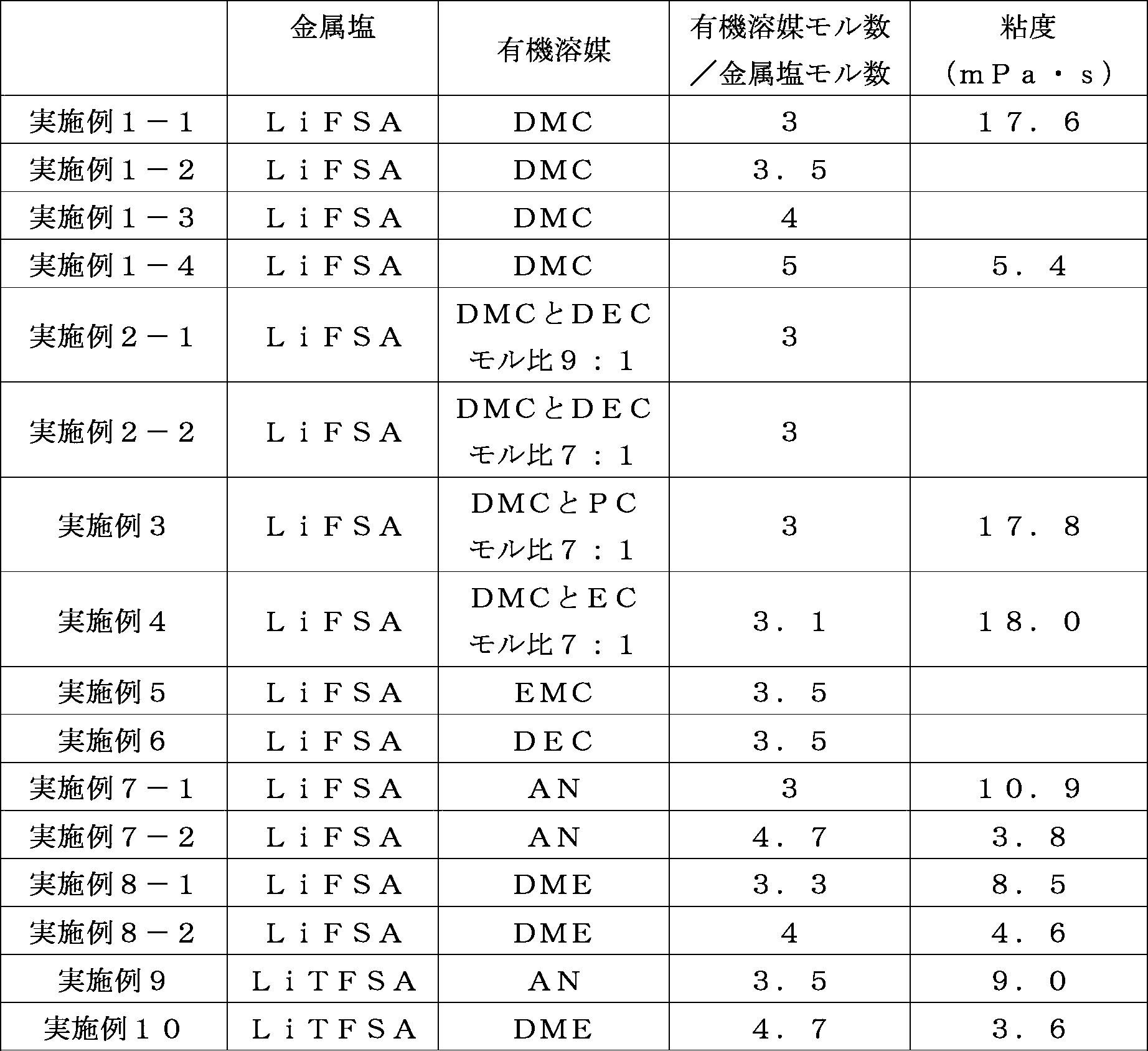

実施例の電解液の粘度は、低すぎることもなく高すぎることもないことがわかる。本発明の電解液で規定する特定有機溶媒と金属塩のモル比の範囲外の電解液では、粘度が低すぎるか、粘度が高すぎる場合があることがわかる。電解液の粘度が低すぎると、そのような電解液を具備する蓄電装置が破損した際には、電解液が大量に漏れるとの懸念がある。他方、電解液の粘度が高すぎると、電解液のイオン伝導特性が低下する懸念や、蓄電装置製造時に電極やセパレータ等への電解液の浸透性が劣るため生産性が低下する懸念がある。
It can be seen that the viscosity of the electrolyte solution of the example is neither too low nor too high. It can be seen that the electrolyte solution outside the range of the molar ratio between the specific organic solvent and the metal salt defined by the electrolyte solution of the present invention may have a viscosity that is too low or too high. If the viscosity of the electrolytic solution is too low, there is a concern that a large amount of the electrolytic solution leaks when a power storage device including such an electrolytic solution is damaged. On the other hand, when the viscosity of the electrolytic solution is too high, there is a concern that the ionic conductivity of the electrolytic solution is lowered, and there is a concern that productivity is lowered because the permeability of the electrolytic solution to the electrode, the separator, or the like is inferior when the power storage device is manufactured.
また、実施例1-1、実施例3、実施例4の電解液の結果をみると、特定有機溶媒の一部を他のヘテロ有機溶媒で置換したヘテロ元素含有有機溶媒を用いた場合には、粘度が増加することがわかる。
In addition, the results of the electrolyte solutions of Example 1-1, Example 3, and Example 4 show that when a hetero element-containing organic solvent in which a part of the specific organic solvent is substituted with another hetero organic solvent is used. It can be seen that the viscosity increases.
(評価例4:低温保管試験)
実施例1-1、実施例1-3、実施例1-4、比較例3-2、比較例3-3の各電解液をそれぞれ容器に入れ、不活性ガスを充填して密閉した。これらを-20℃の冷凍庫に2日間保管した。保管後に各電解液を観察した。結果を表7に示す。 (Evaluation Example 4: Low temperature storage test)
The electrolytic solutions of Example 1-1, Example 1-3, Example 1-4, Comparative Example 3-2, and Comparative Example 3-3 were placed in containers, filled with an inert gas, and sealed. These were stored in a freezer at −20 ° C. for 2 days. Each electrolyte was observed after storage. The results are shown in Table 7.

特定有機溶媒と金属塩のモル比の値が大きくなるほど、すなわち従来の値に近づくほど、低温で凝固しやすくなることがわかる。なお、実施例1-4の電解液は-20℃で2日間保管することで凝固したものの、従来の濃度の電解液である比較例3-3の電解液と比較すると、凝固しがたいといえる。
It turns out that it becomes easy to solidify at low temperature, so that the value of the molar ratio of a specific organic solvent and a metal salt becomes large, ie, it approaches the conventional value. Although the electrolytic solution of Example 1-4 was solidified by storing at −20 ° C. for 2 days, it was difficult to solidify as compared with the electrolytic solution of Comparative Example 3-3, which is a conventional concentration electrolytic solution. I can say that.
(実施例A)
実施例1-1の電解液を用いたハーフセルを以下のとおり製造した。
径13.82mm、面積1.5cm2、厚み20μmのアルミニウム箔(JIS A1000番系)を作用極とし、対極は金属Liとした。セパレータは、厚み400μmのWhatmanガラスフィルター不織布:品番1825-055を用いた。
作用極、対極、セパレータ及び実施例1-1の電解液を電池ケース(宝泉株式会社製 CR2032型コインセルケース)に収容しハーフセルを構成した。これを実施例Aのハーフセルとした。 (Example A)
A half cell using the electrolyte solution of Example 1-1 was produced as follows.
An aluminum foil (JIS A1000 series) having a diameter of 13.82 mm, an area of 1.5 cm 2 and a thickness of 20 μm was used as a working electrode, and the counter electrode was metal Li. As the separator, Whatman glass filter nonwoven fabric having a thickness of 400 μm: product number 1825-055 was used.
A working cell, a counter electrode, a separator, and the electrolyte solution of Example 1-1 were accommodated in a battery case (CR2032 type coin cell case manufactured by Hosen Co., Ltd.) to form a half cell. This was designated as the half cell of Example A.
(比較例A)
比較例3-3の電解液を用いた以外は、実施例Aのハーフセルと同様にして、比較例Aのハーフセルを作製した。 (Comparative Example A)
A half cell of Comparative Example A was produced in the same manner as the half cell of Example A, except that the electrolytic solution of Comparative Example 3-3 was used.
比較例3-3の電解液を用いた以外は、実施例Aのハーフセルと同様にして、比較例Aのハーフセルを作製した。 (Comparative Example A)
A half cell of Comparative Example A was produced in the same manner as the half cell of Example A, except that the electrolytic solution of Comparative Example 3-3 was used.
(評価例A:作用極Alでのサイクリックボルタンメトリー評価)
実施例A及び比較例Aのハーフセルに対して、3.0V~4.5V、1mV/sの条件で、10サイクルのサイクリックボルタンメトリー評価を行い、その後、3.0V~5.0V、1mV/sの条件で、10サイクルのサイクリックボルタンメトリー評価を行った。実施例A及び比較例Aのハーフセルに対する電位と応答電流との関係を示すグラフを図2~図5に示す。 (Evaluation example A: cyclic voltammetry evaluation with working electrode Al)
For the half cells of Example A and Comparative Example A, cyclic voltammetry evaluation was performed for 10 cycles under the conditions of 3.0 V to 4.5 V and 1 mV / s, and then 3.0 V to 5.0 V, 1 mV / s. The cyclic voltammetry evaluation of 10 cycles was performed on condition of s. Graphs showing the relationship between the potential and response current for the half cells of Example A and Comparative Example A are shown in FIGS.
図4及び図5から、比較例Aのハーフセルでは、2サイクル以降も3.0Vから4.5Vにかけて電流が流れ、しかも高電位になるに従い電流が増大していることがわかる。この電流は、作用極のアルミニウムが腐食したことによるAlの酸化電流と推定される。
4 and 5, it can be seen that in the half cell of Comparative Example A, the current flows from 3.0 V to 4.5 V after the second cycle, and the current increases as the potential increases. This current is presumed to be the oxidation current of Al due to the corrosion of the working electrode aluminum.
図2及び図3から、実施例Aのハーフセルにおいては、2サイクル以降は3.0Vから4.5Vにかけてほとんど電流が流れていないことがわかる。特に3サイクル目以降では4.5Vに至るまで電流の増大はほぼない。そして、実施例Aのハーフセルでは高電位となる4.5V以降に電流の増大がみられるが、これは比較例Aのハーフセルにおける4.5V以降の電流値に比べると遙かに小さい値である。
2 and 3, it can be seen that in the half cell of Example A, almost no current flows from 3.0 V to 4.5 V after 2 cycles. In particular, after the third cycle, there is almost no increase in current up to 4.5V. In the half cell of Example A, an increase in current is observed after 4.5 V, which is a high potential, which is much smaller than the current value after 4.5 V in the half cell of Comparative Example A. .
サイクリックボルタンメトリー評価の結果から、少なくとも4.5V程度の高電位条件でも、実施例1-1の電解液のアルミニウムに対する腐食性や酸化分解性は低いといえる。すなわち、実施例1-1の電解液は、集電体などにアルミニウムを用いた蓄電装置に対し、好適な電解液といえる。
From the results of the cyclic voltammetry evaluation, it can be said that the corrosiveness and oxidative decomposability of the electrolytic solution of Example 1-1 to aluminum are low even under a high potential condition of at least about 4.5V. That is, the electrolytic solution of Example 1-1 can be said to be a preferable electrolytic solution for a power storage device using aluminum as a current collector or the like.
(参考例A)
比較例3-2の電解液を用いたハーフセルを以下のとおり製造した。
活物質である平均粒径10μmの黒鉛90質量部、及び結着剤であるポリフッ化ビニリデン10質量部を混合した。この混合物を適量のN-メチル-2-ピロリドンに分散させて、スラリーを作製した。集電体として厚み20μmの銅箔を準備した。この銅箔の表面に、ドクターブレードを用いて、上記スラリーを膜状に塗布した。スラリーが塗布された銅箔を乾燥してN-メチル-2-ピロリドンを除去し、その後、銅箔をプレスし、接合物を得た。得られた接合物を真空乾燥機で120℃、6時間加熱乾燥して、活物質層が形成された銅箔を得た。これを作用極とした。 (Reference Example A)
A half cell using the electrolytic solution of Comparative Example 3-2 was produced as follows.
90 parts by mass of graphite having an average particle diameter of 10 μm as an active material and 10 parts by mass of polyvinylidene fluoride as a binder were mixed. This mixture was dispersed in an appropriate amount of N-methyl-2-pyrrolidone to prepare a slurry. A copper foil having a thickness of 20 μm was prepared as a current collector. The slurry was applied in a film form on the surface of the copper foil using a doctor blade. The copper foil coated with the slurry was dried to remove N-methyl-2-pyrrolidone, and then the copper foil was pressed to obtain a bonded product. The obtained joined product was heat-dried at 120 ° C. for 6 hours with a vacuum dryer to obtain a copper foil on which an active material layer was formed. This was the working electrode.
対極は金属Liとした。
The counter electrode was metal Li.
作用極、対極、両者の間に挟装したセパレータとしての厚さ400μmのWhatmanガラス繊維ろ紙及び比較例3-2の電解液を電池ケース(宝泉株式会社製 CR2032型コインセルケース)に収容しハーフセルを構成した。これを参考例Aのハーフセルとした。
A working cell, a counter electrode, a 400 μm-thick Whatman glass fiber filter paper as a separator sandwiched between them, and the electrolyte of Comparative Example 3-2 are accommodated in a battery case (CR2032 type coin cell case manufactured by Hosen Co., Ltd.) and a half cell. Configured. This was designated as the half cell of Reference Example A.
(参考例B)
電解液として比較例9-1の電解液を用いた以外は、参考例Aと同様の方法で、参考例Bのハーフセルを製造した。 (Reference Example B)
A half cell of Reference Example B was produced in the same manner as Reference Example A, except that the electrolyte of Comparative Example 9-1 was used as the electrolyte.
電解液として比較例9-1の電解液を用いた以外は、参考例Aと同様の方法で、参考例Bのハーフセルを製造した。 (Reference Example B)
A half cell of Reference Example B was produced in the same manner as Reference Example A, except that the electrolyte of Comparative Example 9-1 was used as the electrolyte.
(参考例C)
電解液として比較例9-2の電解液を用いた以外は、参考例Aと同様の方法で、参考例Cのハーフセルを製造した。 (Reference Example C)
A half cell of Reference Example C was produced in the same manner as Reference Example A, except that the electrolyte of Comparative Example 9-2 was used as the electrolyte.
電解液として比較例9-2の電解液を用いた以外は、参考例Aと同様の方法で、参考例Cのハーフセルを製造した。 (Reference Example C)
A half cell of Reference Example C was produced in the same manner as Reference Example A, except that the electrolyte of Comparative Example 9-2 was used as the electrolyte.
(参考例D)
電解液として比較例9-3の電解液を用いた以外は、参考例Aと同様の方法で、参考例Dのハーフセルを製造した。 (Reference Example D)
A half cell of Reference Example D was produced in the same manner as Reference Example A, except that the electrolyte of Comparative Example 9-3 was used as the electrolyte.
電解液として比較例9-3の電解液を用いた以外は、参考例Aと同様の方法で、参考例Dのハーフセルを製造した。 (Reference Example D)
A half cell of Reference Example D was produced in the same manner as Reference Example A, except that the electrolyte of Comparative Example 9-3 was used as the electrolyte.
(参考例E)
電解液として比較例9-4の電解液を用いた以外は、参考例Aと同様の方法で、参考例Eのハーフセルを製造した。 (Reference Example E)
A half cell of Reference Example E was produced in the same manner as Reference Example A, except that the electrolyte of Comparative Example 9-4 was used as the electrolyte.
電解液として比較例9-4の電解液を用いた以外は、参考例Aと同様の方法で、参考例Eのハーフセルを製造した。 (Reference Example E)
A half cell of Reference Example E was produced in the same manner as Reference Example A, except that the electrolyte of Comparative Example 9-4 was used as the electrolyte.
(参考評価例A:レート容量試験)
参考例A~Eのハーフセルのレート容量を以下の方法で試験した。
各ハーフセルに対し、2.0Vから0.01Vまでの放電及び0.01Vから2.0Vまでの充電を、0.1C、0.2C、0.5C、1C、2C、5C、10C及び0.1Cレートの順序で、各レートにつき3回ずつ行う充放電サイクル試験を行った。初めの0.1Cレートでの2回目の放電容量に対する、5Cレート及び10Cレートでの2回目の放電容量の比率を算出した結果を表8に示す。なお、ここでの記述は、対極を負極、作用極を正極とみなしている。1Cとは一定電流において1時間で電池を完全充電又は放電させるために要する電流値を意味する。 (Reference evaluation example A: rate capacity test)
The rate capacities of the half cells of Reference Examples A to E were tested by the following method.
For each half-cell, discharging from 2.0 V to 0.01 V and charging from 0.01 V to 2.0 V are performed at 0.1 C, 0.2 C, 0.5 C, 1 C, 2 C, 5 C, 10 C, and 0. A charge / discharge cycle test was performed three times for each rate in the order of 1C rate. Table 8 shows the results of calculating the ratio of the second discharge capacity at the 5C rate and the 10C rate to the first discharge capacity at the first 0.1C rate. In this description, the counter electrode is regarded as a negative electrode and the working electrode is regarded as a positive electrode. 1C means a current value required to fully charge or discharge a battery in one hour at a constant current.

表8から、電解液のヘテロ元素含有有機溶媒において、特定有機溶媒の比率が低くなるに従い、換言すると高誘電率及び高双極子モーメントを示す他のヘテロ有機溶媒の比率が高くなるに従い、セルの高レートでの容量が低下することがわかる。この事実は、電解液のヘテロ元素含有有機溶媒において、特定有機溶媒の比率が低くなるに従い、又は、他のヘテロ有機溶媒の比率が高くなるに従い、電極における反応抵抗が大きくなることを示唆している。
From Table 8, in the heteroelement-containing organic solvent of the electrolytic solution, as the ratio of the specific organic solvent decreases, in other words, as the ratio of the other heteroorganic solvent exhibiting a high dielectric constant and a high dipole moment increases, It can be seen that the capacity at the high rate decreases. This fact suggests that the reaction resistance at the electrode increases as the ratio of the specific organic solvent decreases or the ratio of the other hetero organic solvent increases in the heteroelement-containing organic solvent of the electrolyte. Yes.
(参考実施例I)
実施例1-1の電解液を用いた参考実施例Iのリチウムイオン二次電池を以下のとおり製造した。 (Reference Example I)
A lithium ion secondary battery of Reference Example I using the electrolyte solution of Example 1-1 was produced as follows.
実施例1-1の電解液を用いた参考実施例Iのリチウムイオン二次電池を以下のとおり製造した。 (Reference Example I)
A lithium ion secondary battery of Reference Example I using the electrolyte solution of Example 1-1 was produced as follows.
正極活物質であるLiNi5/10Co2/10Mn3/10O2で表される層状岩塩構造のリチウム含有金属酸化物90質量部、導電助剤であるアセチレンブラック8質量部、及び結着剤であるポリフッ化ビニリデン2質量部を混合した。この混合物を適量のN-メチル-2-ピロリドンに分散させて、スラリーを作製した。正極集電体として厚み20μmのアルミニウム箔を準備した。このアルミニウム箔の表面に、ドクターブレードを用いて上記スラリーが膜状になるように塗布した。スラリーが塗布されたアルミニウム箔を80℃で20分間乾燥することでN-メチル-2-ピロリドンを揮発により除去した。その後、このアルミニウム箔をプレスし接合物を得た。得られた接合物を真空乾燥機で120℃、6時間加熱乾燥して、正極活物質層が形成されたアルミニウム箔を得た。これを正極とした。
90 parts by mass of a lithium-containing metal oxide having a layered rock salt structure represented by LiNi 5/10 Co 2/10 Mn 3/10 O 2 as a positive electrode active material, 8 parts by mass of acetylene black as a conductive auxiliary agent, and a binder 2 parts by mass of polyvinylidene fluoride as an agent was mixed. This mixture was dispersed in an appropriate amount of N-methyl-2-pyrrolidone to prepare a slurry. An aluminum foil having a thickness of 20 μm was prepared as a positive electrode current collector. The slurry was applied to the surface of the aluminum foil using a doctor blade so as to form a film. The aluminum foil coated with the slurry was dried at 80 ° C. for 20 minutes to remove N-methyl-2-pyrrolidone by volatilization. Thereafter, this aluminum foil was pressed to obtain a bonded product. The obtained joined product was heat-dried at 120 ° C. for 6 hours with a vacuum dryer to obtain an aluminum foil on which a positive electrode active material layer was formed. This was used as a positive electrode.
負極活物質である球状黒鉛98質量部、並びに結着剤であるスチレンブタジエンゴム1質量部及びカルボキシメチルセルロース1質量部を混合した。この混合物を適量のイオン交換水に分散させて、スラリーを作製した。負極集電体として厚み20μmの銅箔を準備した。この銅箔の表面に、ドクターブレードを用いて、上記スラリーを膜状に塗布した。スラリーが塗布された銅箔を乾燥して水を除去し、その後、銅箔をプレスし、接合物を得た。得られた接合物を真空乾燥機で100℃、6時間加熱乾燥して、負極活物質層が形成された銅箔を得た。これを負極とした。
98 parts by mass of spherical graphite as a negative electrode active material, 1 part by mass of styrene butadiene rubber as a binder, and 1 part by mass of carboxymethyl cellulose were mixed. This mixture was dispersed in an appropriate amount of ion-exchanged water to prepare a slurry. A copper foil having a thickness of 20 μm was prepared as a negative electrode current collector. The slurry was applied in a film form on the surface of the copper foil using a doctor blade. The copper foil coated with the slurry was dried to remove water, and then the copper foil was pressed to obtain a bonded product. The obtained joined product was dried by heating at 100 ° C. for 6 hours with a vacuum dryer to obtain a copper foil on which a negative electrode active material layer was formed. This was used as a negative electrode.
セパレータとして、厚さ20μmのセルロース製不織布を準備した。
A cellulose nonwoven fabric having a thickness of 20 μm was prepared as a separator.
正極と負極とでセパレータを挟持し、極板群とした。この極板群を二枚一組のラミネートフィルムで覆い、三辺をシールした後、袋状となったラミネートフィルムに実施例1-1の電解液を注入した。その後、残りの一辺をシールすることで、四辺が気密にシールされ、極板群及び電解液が密閉されたリチウムイオン二次電池を得た。この電池を参考実施例Iのリチウムイオン二次電池とした。
A separator was sandwiched between the positive electrode and the negative electrode to form an electrode plate group. The electrode plate group was covered with a set of two laminated films, the three sides were sealed, and then the electrolyte solution of Example 1-1 was poured into the bag-like laminated film. Thereafter, the remaining one side was sealed to obtain a lithium ion secondary battery in which the four sides were hermetically sealed and the electrode plate group and the electrolyte were sealed. This battery was a lithium ion secondary battery of Reference Example I.
(参考実施例II)
電解液として実施例1-3の電解液を用いた以外は、参考実施例Iと同様の方法で、参考実施例IIのリチウムイオン二次電池を得た。 (Reference Example II)
A lithium ion secondary battery of Reference Example II was obtained in the same manner as Reference Example I, except that the electrolyte of Example 1-3 was used as the electrolyte.
電解液として実施例1-3の電解液を用いた以外は、参考実施例Iと同様の方法で、参考実施例IIのリチウムイオン二次電池を得た。 (Reference Example II)
A lithium ion secondary battery of Reference Example II was obtained in the same manner as Reference Example I, except that the electrolyte of Example 1-3 was used as the electrolyte.
(参考比較例I)
電解液として比較例3-2の電解液を用いた以外は、参考実施例Iと同様の方法で、参考比較例Iのリチウムイオン二次電池を得た。 (Reference Comparative Example I)
A lithium ion secondary battery of Reference Comparative Example I was obtained in the same manner as Reference Example I, except that the electrolyte of Comparative Example 3-2 was used as the electrolyte.
(参考比較例II)
電解液として比較例4-2の電解液を用いた以外は、参考実施例Iと同様の方法で、参考比較例IIのリチウムイオン二次電池を得た。 (Reference Comparative Example II)
A lithium ion secondary battery of Reference Comparative Example II was obtained in the same manner as Reference Example I, except that the electrolyte of Comparative Example 4-2 was used as the electrolyte.
(参考比較例III)
電解液として比較例8の電解液を用いた以外は、参考実施例Iと同様の方法で、参考比較例IIIのリチウムイオン二次電池を得た。 (Reference Comparative Example III)
A lithium ion secondary battery of Reference Comparative Example III was obtained in the same manner as Reference Example I, except that the electrolytic solution of Comparative Example 8 was used as the electrolytic solution.
(参考評価例I:電池の内部抵抗)
参考実施例I~II、参考比較例I~IIIのリチウムイオン二次電池につき、以下の方法で、電池の内部抵抗を評価した。
各リチウムイオン二次電池について、室温、3.0V~4.1V(vs.Li基準)の範囲でCC充放電、つまり定電流充放電を繰り返した。そして、初回充放電後の交流インピーダンス、及び、100サイクル経過後の交流インピーダンスを測定した。得られた複素インピーダンス平面プロットを基に、電解液、負極及び正極の反応抵抗を各々解析した。図6に示すように、複素インピーダンス平面プロットには、二つの円弧がみられた。図6中左側、つまり複素インピーダンスの実部が小さい側の円弧を第1円弧と呼ぶ。図6中右側の円弧を第2円弧と呼ぶ。第1円弧の大きさを基に負極の反応抵抗を解析し、第2円弧の大きさを基に正極の反応抵抗を解析した。第1円弧に連続する図6中最左側のプロットを基に電解液の抵抗を解析した。解析結果を表9及び表10に示す。なお、表9は、初回充放電後の電解液の抵抗(所謂溶液抵抗)、負極の反応抵抗、正極の反応抵抗を示し、表10は100サイクル経過後の各抵抗を示す。 (Reference Evaluation Example I: Internal resistance of battery)
For the lithium ion secondary batteries of Reference Examples I to II and Reference Comparative Examples I to III, the internal resistance of the batteries was evaluated by the following method.
For each lithium ion secondary battery, CC charge / discharge, that is, constant current charge / discharge was repeated at room temperature in the range of 3.0 V to 4.1 V (vs. Li standard). And the alternating current impedance after the first charge / discharge and the alternating current impedance after 100 cycles progress were measured. Based on the obtained complex impedance plane plot, the reaction resistances of the electrolytic solution, the negative electrode, and the positive electrode were each analyzed. As shown in FIG. 6, two arcs were seen in the complex impedance plane plot. The arc on the left side in FIG. 6, that is, the side where the real part of the complex impedance is small is called a first arc. The arc on the right side in FIG. 6 is called the second arc. The reaction resistance of the negative electrode was analyzed based on the size of the first arc, and the reaction resistance of the positive electrode was analyzed based on the size of the second arc. The resistance of the electrolytic solution was analyzed based on the leftmost plot in FIG. 6 continuous with the first arc. The analysis results are shown in Tables 9 and 10. Table 9 shows the resistance (so-called solution resistance) of the electrolytic solution after the first charge / discharge, the reaction resistance of the negative electrode, and the reaction resistance of the positive electrode, and Table 10 shows each resistance after 100 cycles.

表9の参考実施例I、参考実施例II、参考比較例Iの結果から、特定有機溶媒と金属塩のモル比が大きくなるほど、溶液抵抗が低下することがわかる。表4及び図1のイオン伝導度の結果と併せて考察すると、特定有機溶媒と金属塩のモル比3~5の範囲内の本発明の電解液が、イオン伝導度及び反応抵抗の両者を好適に満たす電解液であることがわかる。また、参考比較例IIIのリチウムイオン二次電池は、正極反応抵抗が著しく高かった。
From the results of Reference Example I, Reference Example II, and Reference Comparative Example I in Table 9, it can be seen that the solution resistance decreases as the molar ratio of the specific organic solvent to the metal salt increases. When considered together with the results of ionic conductivity shown in Table 4 and FIG. 1, the electrolyte solution of the present invention within the range of the molar ratio of the specific organic solvent to the metal salt of 3 to 5 is suitable for both ionic conductivity and reaction resistance. It can be seen that the electrolyte solution satisfies the above. Further, the lithium ion secondary battery of Reference Comparative Example III had remarkably high positive electrode reaction resistance.

表9及び表10から、特定有機溶媒がDMCであり金属塩がLiFSAの電解液を具備するリチウムイオン二次電池は、充放電サイクル後の溶液抵抗、負極反応抵抗及び正極反応抵抗がいずれも、初期と比べて同等又は低下することがわかる。他方、特定有機溶媒がANであり金属塩がLiFSAの電解液を具備するリチウムイオン二次電池は、充放電サイクル後の正極反応抵抗が、初期と比べて増加することがわかる。
From Table 9 and Table 10, the lithium ion secondary battery comprising an electrolyte solution in which the specific organic solvent is DMC and the metal salt is LiFSA has a solution resistance, a negative electrode reaction resistance, and a positive electrode reaction resistance after charge / discharge cycles. It turns out that it is equivalent or falls compared with the initial stage. On the other hand, it can be seen that in the lithium ion secondary battery including the electrolyte in which the specific organic solvent is AN and the metal salt is LiFSA, the positive electrode reaction resistance after the charge / discharge cycle is increased compared to the initial stage.
(参考評価例II:容量維持率)
参考実施例I~II、参考比較例I~IIIのリチウムイオン二次電池につき、以下の方法で、容量維持率を評価した。
各リチウムイオン二次電池について、室温、3.0V~4.1V(vs.Li基準)の範囲でCC充放電を繰り返した。初回充放電時の放電容量、及び、300サイクル時の放電容量を測定した。そして、初回充放電時の各リチウムイオン二次電池の容量を100%として、300サイクル時の各リチウムイオン二次電池の容量維持率(%)を算出した。結果を表11に示す。 (Reference Evaluation Example II: Capacity maintenance rate)
The capacity retention rates of the lithium ion secondary batteries of Reference Examples I to II and Reference Comparative Examples I to III were evaluated by the following method.
For each lithium ion secondary battery, CC charge / discharge was repeated at room temperature in the range of 3.0 V to 4.1 V (vs. Li standard). The discharge capacity at the first charge / discharge and the discharge capacity at 300 cycles were measured. And the capacity | capacitance maintenance factor (%) of each lithium ion secondary battery at the time of 300 cycles was computed by making the capacity | capacitance of each lithium ion secondary battery at the time of initial charge / discharge into 100%. The results are shown in Table 11.

参考実施例I~IIのリチウムイオン二次電池は、参考比較例I~IIIのリチウムイオン二次電池と比較して、同等以上の容量維持率を示した。本発明の電解液を具備するリチウムイオン二次電池は、充放電サイクルに対し、優れた耐久性を示すことが裏付けられた。
The lithium ion secondary batteries of Reference Examples I to II showed a capacity maintenance rate equal to or higher than the lithium ion secondary batteries of Reference Comparative Examples I to III. It was confirmed that the lithium ion secondary battery comprising the electrolytic solution of the present invention exhibits excellent durability against charge / discharge cycles.
(参考評価例III:電極のS及びO含有皮膜の分析)
参考評価例II前及び参考評価例IIを経た参考実施例IIのリチウムイオン二次電池をそれぞれ解体して正極を取出し、当該正極をジメチルカーボネートで3回洗浄後、乾燥して、分析対象の正極とした。なお、リチウムイオン二次電池の解体から分析対象としての正極を分析装置に搬送するまでの全ての工程を、Arガス雰囲気下で行った。X線光電子分光法を用いて、以下の条件で、分析対象の正極を分析した。硫黄元素についての分析チャートを図7に、酸素元素についての分析チャートを図8に、それぞれ示す。各図において、点線が参考評価例II前の参考実施例IIのリチウムイオン二次電池の正極のピークであり、実線が参考評価例IIを経た参考実施例IIのリチウムイオン二次電池の正極のピークである。 (Reference Evaluation Example III: Analysis of S and O-containing film of electrode)
The lithium ion secondary battery of Reference Example II passed through Reference Evaluation Example II and Reference Evaluation Example II was disassembled, and the positive electrode was taken out. The positive electrode was washed three times with dimethyl carbonate, dried, and then analyzed. It was. In addition, all the processes from the disassembly of the lithium ion secondary battery to the conveyance of the positive electrode as the analysis target to the analyzer were performed in an Ar gas atmosphere. The positive electrode to be analyzed was analyzed under the following conditions using X-ray photoelectron spectroscopy. FIG. 7 shows an analysis chart for the sulfur element, and FIG. 8 shows an analysis chart for the oxygen element. In each figure, the dotted line is the peak of the positive electrode of the lithium ion secondary battery of Reference Example II before Reference Evaluation Example II, and the solid line is the positive electrode of the lithium ion secondary battery of Reference Example II after Reference Evaluation Example II. It is a peak.
装置:アルバックファイ社 PHI5000 VersaProbeII
X線源:単色AlKα線、電圧15kV、電流10mA Device: ULVAC-PHI PHI5000 VersaProbeII
X-ray source: Monochromatic AlKα ray,voltage 15 kV, current 10 mA
X線源:単色AlKα線、電圧15kV、電流10mA Device: ULVAC-PHI PHI5000 VersaProbeII
X-ray source: Monochromatic AlKα ray,
図7及び図8から、参考評価例IIを経た参考実施例IIのリチウムイオン二次電池の正極には、新たにS及びO含有皮膜が形成されたことがわかる。図7に観察される、170eV付近のピークはS=O結合に由来するピークと考えられる。そのため、上記正極のS及びO含有皮膜には、S=O結合が存在するといえる。そして、参考実施例IIのリチウムイオン二次電池は、S及びS=O結合を有する金属塩を具備し、これ以外にS又はS=O結合を有するものを具備しないことから、上記正極のS及びO含有皮膜のS又はS=O結合は、当該金属塩に由来するものといえる。
7 and 8, it can be seen that an S- and O-containing coating is newly formed on the positive electrode of the lithium ion secondary battery of Reference Example II that has passed Reference Evaluation Example II. The peak near 170 eV observed in FIG. 7 is considered to be a peak derived from S═O bond. Therefore, it can be said that S = O bond exists in the S and O containing film of the positive electrode. The lithium ion secondary battery of Reference Example II includes a metal salt having S and S═O bond, and does not have any other one having S or S═O bond. And the S or S = O bond of the O-containing film can be said to be derived from the metal salt.
(参考評価例IV:Ni、Mn、Coの溶出確認)
参考実施例II及び参考比較例IIのリチウムイオン二次電池につき、以下の方法で、負極におけるNi、Mn、Coの沈着量を分析した。
各リチウムイオン二次電池につき、60℃、3.0V~4.1Vの範囲で1Cレートにて定電流充放電を200回繰り返した。その後、各リチウムイオン二次電池を解体し、負極を取り出した。負極の表面へ沈着したNi、Mn、Coの量を高周波誘導結合プラズマ発光分光法にて分析した。測定結果を表12に示す。表のNi、Mn、Co量(%)は、負極活物質層のNi、Mn、Coの質量の割合である。 (Reference Evaluation Example IV: Confirmation of elution of Ni, Mn and Co)
For the lithium ion secondary batteries of Reference Example II and Reference Comparative Example II, the amounts of Ni, Mn, and Co deposited on the negative electrode were analyzed by the following method.
For each lithium ion secondary battery, constant current charging / discharging was repeated 200 times at a 1C rate in the range of 3.0V to 4.1V at 60 ° C. Thereafter, each lithium ion secondary battery was disassembled, and the negative electrode was taken out. The amount of Ni, Mn and Co deposited on the surface of the negative electrode was analyzed by high frequency inductively coupled plasma emission spectroscopy. Table 12 shows the measurement results. The amounts of Ni, Mn, and Co (%) in the table are the mass ratios of Ni, Mn, and Co in the negative electrode active material layer.

参考実施例IIのリチウムイオン二次電池の負極において、Ni、Mn、Co量は、それぞれの元素の検出限界未満であった。他方、参考比較例IIのリチウムイオン二次電池の負極においては、Ni、Mn、Coが、いずれも検出された。ここで、負極から検出されたNi、Mn、Coは、正極から電解液に溶出し、負極に沈着したものと推測される。すなわち、本発明の電解液を具備する参考実施例IIのリチウムイオン二次電池においては、正極の遷移金属が本発明の電解液に極めて溶出しがたいといえる。換言すると、本発明の電解液は、正極からの遷移金属の溶出を好適に抑制するといえる。
In the negative electrode of the lithium ion secondary battery of Reference Example II, the amounts of Ni, Mn, and Co were less than the detection limit of each element. On the other hand, Ni, Mn, and Co were all detected in the negative electrode of the lithium ion secondary battery of Reference Comparative Example II. Here, it is presumed that Ni, Mn, and Co detected from the negative electrode are eluted from the positive electrode into the electrolytic solution and deposited on the negative electrode. That is, in the lithium ion secondary battery of Reference Example II having the electrolytic solution of the present invention, it can be said that the transition metal of the positive electrode is extremely difficult to elute into the electrolytic solution of the present invention. In other words, it can be said that the electrolytic solution of the present invention suitably suppresses the elution of transition metal from the positive electrode.
(参考実施例III)
実施例1-2の電解液を具備する参考実施例IIIのリチウムイオン二次電池を以下のとおり製造した。 (Reference Example III)
A lithium ion secondary battery of Reference Example III comprising the electrolyte solution of Example 1-2 was produced as follows.
実施例1-2の電解液を具備する参考実施例IIIのリチウムイオン二次電池を以下のとおり製造した。 (Reference Example III)
A lithium ion secondary battery of Reference Example III comprising the electrolyte solution of Example 1-2 was produced as follows.
正極活物質であるLiNi5/10Co2/10Mn3/10O2を90質量部、導電助剤であるアセチレンブラック8質量部、及び結着剤であるポリフッ化ビニリデン2質量部を混合した。この混合物を適量のN-メチル-2-ピロリドンに分散させて、スラリーを作製した。正極用集電体として厚み20μmのJIS A1000番系に該当するアルミニウム箔を準備した。このアルミニウム箔の表面に、ドクターブレードを用いて上記スラリーが膜状になるように塗布した。スラリーが塗布されたアルミニウム箔を80℃で20分間乾燥することで、N-メチル-2-ピロリドンを除去した。その後、このアルミニウム箔をプレスし接合物を得た。得られた接合物を真空乾燥機で120℃、6時間加熱乾燥して、正極活物質層が形成されたアルミニウム箔を得た。これを正極とした。なお、正極活物質層は正極集電体上に塗工面単位面積あたり5.5mg/cm2で形成されており、また、正極活物質層の密度は2.4g/cm3であった。
90 parts by mass of LiNi 5/10 Co 2/10 Mn 3/10 O 2 as a positive electrode active material, 8 parts by mass of acetylene black as a conductive additive, and 2 parts by mass of polyvinylidene fluoride as a binder were mixed. . This mixture was dispersed in an appropriate amount of N-methyl-2-pyrrolidone to prepare a slurry. An aluminum foil corresponding to JIS A1000 series having a thickness of 20 μm was prepared as a positive electrode current collector. The slurry was applied to the surface of the aluminum foil using a doctor blade so as to form a film. The aluminum foil coated with the slurry was dried at 80 ° C. for 20 minutes to remove N-methyl-2-pyrrolidone. Thereafter, this aluminum foil was pressed to obtain a bonded product. The obtained joined product was heat-dried at 120 ° C. for 6 hours with a vacuum dryer to obtain an aluminum foil on which a positive electrode active material layer was formed. This was used as a positive electrode. The positive electrode active material layer was formed on the positive electrode current collector at 5.5 mg / cm 2 per unit area of the coated surface, and the density of the positive electrode active material layer was 2.4 g / cm 3 .
負極活物質として球状黒鉛98質量部、並びに結着剤であるスチレンブタジエンゴム1質量部及びカルボキシメチルセルロース1質量部を混合した。この混合物を適量のイオン交換水に分散させて、スラリーを作製した。負極用集電体として厚み20μmの銅箔を準備した。この銅箔の表面に、ドクターブレードを用いて、上記スラリーを膜状に塗布した。スラリーが塗布された銅箔を乾燥して水を除去し、その後、銅箔をプレスし、接合物を得た。得られた接合物を真空乾燥機で100℃、6時間加熱乾燥して、負極活物質層が形成された銅箔を得た。これを負極とした。なお、負極活物質層は負極集電体上に塗工面単位面積あたり3.8mg/cm2で形成されており、また、負極活物質層の密度は1.1g/cm3であった。
As a negative electrode active material, 98 parts by mass of spherical graphite, 1 part by mass of styrene butadiene rubber as a binder and 1 part by mass of carboxymethyl cellulose were mixed. This mixture was dispersed in an appropriate amount of ion-exchanged water to prepare a slurry. A copper foil having a thickness of 20 μm was prepared as a negative electrode current collector. The slurry was applied in a film form on the surface of the copper foil using a doctor blade. The copper foil coated with the slurry was dried to remove water, and then the copper foil was pressed to obtain a bonded product. The obtained joined product was dried by heating at 100 ° C. for 6 hours with a vacuum dryer to obtain a copper foil on which a negative electrode active material layer was formed. This was used as a negative electrode. Note that the negative electrode active material layer was formed on the negative electrode current collector at 3.8 mg / cm 2 per unit area of the coated surface, and the density of the negative electrode active material layer was 1.1 g / cm 3 .
セパレータとして、厚さ20μmのセルロース製不織布を準備した。
正極と負極とでセパレータを挟持し、極板群とした。この極板群を二枚一組のラミネートフィルムで覆い、三辺をシールした後、袋状となったラミネートフィルムに実施例1-2の電解液を注入した。その後、残りの一辺をシールすることで、四辺が気密にシールされ、極板群及び電解液が密閉されたリチウムイオン二次電池を得た。この電池を参考実施例IIIのリチウムイオン二次電池とした。 A cellulose nonwoven fabric having a thickness of 20 μm was prepared as a separator.
A separator was sandwiched between the positive electrode and the negative electrode to form an electrode plate group. The electrode plate group was covered with a set of two laminated films, and the three sides were sealed. Then, the electrolytic solution of Example 1-2 was injected into the bag-like laminated film. Thereafter, the remaining one side was sealed to obtain a lithium ion secondary battery in which the four sides were hermetically sealed and the electrode plate group and the electrolyte were sealed. This battery was designated as a lithium ion secondary battery of Reference Example III.
(参考実施例IV)
電解液として実施例1-3の電解液を用いたこと以外は、参考実施例IIIと同様にして参考実施例IVのリチウムイオン二次電池を得た。 (Reference Example IV)
A lithium ion secondary battery of Reference Example IV was obtained in the same manner as Reference Example III, except that the electrolyte of Example 1-3 was used as the electrolyte.
電解液として実施例1-3の電解液を用いたこと以外は、参考実施例IIIと同様にして参考実施例IVのリチウムイオン二次電池を得た。 (Reference Example IV)
A lithium ion secondary battery of Reference Example IV was obtained in the same manner as Reference Example III, except that the electrolyte of Example 1-3 was used as the electrolyte.
(参考比較例IV)
電解液として比較例3-2の電解液を用いたこと以外は、参考実施例IIIと同様にして参考比較例IVのリチウムイオン二次電池を得た。 (Reference Comparative Example IV)
A lithium ion secondary battery of Reference Comparative Example IV was obtained in the same manner as Reference Example III, except that the electrolyte of Comparative Example 3-2 was used as the electrolyte.
(参考比較例V)
電解液として比較例4-2の電解液を用いたこと以外は、参考実施例IIIと同様にして参考比較例Vのリチウムイオン二次電池を得た。 (Reference Comparative Example V)
A lithium ion secondary battery of Reference Comparative Example V was obtained in the same manner as Reference Example III, except that the electrolyte of Comparative Example 4-2 was used as the electrolyte.
(参考比較例VI)
電解液として比較例8の電解液を用いたこと以外は、参考実施例IIIと同様にして参考比較例VIのリチウムイオン二次電池を得た。 (Reference Comparative Example VI)
A lithium ion secondary battery of Reference Comparative Example VI was obtained in the same manner as Reference Example III, except that the electrolytic solution of Comparative Example 8 was used as the electrolytic solution.
(参考評価例V:容量維持率<2>と直流抵抗)
参考実施例III、参考実施例IV、参考比較例IV~参考比較例VIのリチウムイオン二次電池につき、以下の試験を行い、容量維持率と直流抵抗を評価した。 (Reference Evaluation Example V: Capacity maintenance ratio <2> and DC resistance)
The lithium ion secondary batteries of Reference Example III, Reference Example IV, and Reference Comparative Example IV to Reference Comparative Example VI were subjected to the following tests to evaluate the capacity retention rate and DC resistance.
各リチウムイオン二次電池につき、温度25℃、1Cレートでの定電流で4.1Vまで充電し、1分間休止した後、1Cレートでの定電流で3.0Vまで放電し、1分間休止するとの充放電サイクルを300サイクル繰り返した。容量維持率を以下の式で算出した。
容量維持率(%)=100×(300サイクルでの放電容量)/(初回の放電容量) For each lithium ion secondary battery, charge to 4.1 V at a constant current at a temperature of 25 ° C. and 1 C rate, pause for 1 minute, discharge to 3.0 V at a constant current at 1 C rate, and pause for 1 minute. The charge / discharge cycle was repeated 300 cycles. The capacity maintenance rate was calculated by the following formula.
Capacity maintenance rate (%) = 100 × (discharge capacity at 300 cycles) / (initial discharge capacity)
また、300サイクル後の各リチウムイオン二次電池につき、温度25℃、0.5Cレートの定電流にて電圧3.5Vに調整した後、3Cレートで10秒の定電流放電をした際の前後の電圧変化量及び電流値から、オームの法則により放電時の直流抵抗を算出した。
Also, for each lithium ion secondary battery after 300 cycles, the voltage was adjusted to 3.5 V at a constant current of 25 ° C. and a constant current of 0.5 C, and then discharged at a constant current of 10 seconds at a 3 C rate. From the voltage change amount and the current value, the direct current resistance during discharge was calculated according to Ohm's law.
さらに、300サイクル後の各リチウムイオン二次電池につき、温度25℃、0.5Cレートの定電流にて電圧3.5Vに調整した後、3Cレートで10秒の定電流充電をした際の前後の電圧変化量及び電流値からオームの法則により充電時の直流抵抗を算出した。
Further, for each lithium ion secondary battery after 300 cycles, the voltage was adjusted to 3.5 V at a constant current of 25 ° C. and a constant current of 0.5 C, and then charged at a constant current of 10 seconds at a 3 C rate. The direct current resistance at the time of charging was calculated from the voltage change amount and the current value according to Ohm's law.
以上の試験結果を表13に示す。
Table 13 shows the above test results.

表13の結果から、本発明の電解液を具備するリチウムイオン二次電池は、充放電サイクル後でも好適に容量を維持し、充放電時の直流抵抗が小さいことがわかる。他方、参考比較例IV及び参考比較例VIのリチウムイオン二次電池は充放電時の直流抵抗が大きいこと、参考比較例Vのリチウムイオン二次電池は容量の維持率に劣ることがわかる。
From the results in Table 13, it can be seen that the lithium ion secondary battery comprising the electrolytic solution of the present invention suitably maintains the capacity even after the charge / discharge cycle and has a low DC resistance during charge / discharge. On the other hand, it can be seen that the lithium ion secondary batteries of Reference Comparative Example IV and Reference Comparative Example VI have a large DC resistance during charging and discharging, and the lithium ion secondary battery of Reference Comparative Example V is inferior in capacity retention.
(参考実施例V)
電解液として実施例1-1の電解液を用いたこと及び正極活物質層の密度が2.3g/cm3であったこと以外は、参考実施例IIIと同様にして参考実施例Vのリチウムイオン二次電池を得た。 (Reference Example V)
The lithium of Reference Example V was the same as Reference Example III, except that the electrolyte of Example 1-1 was used as the electrolyte and the density of the positive electrode active material layer was 2.3 g / cm 3. An ion secondary battery was obtained.
(参考実施例VI)
電解液として実施例2-1の電解液を用いたこと以外は、参考実施例Vと同様にして参考実施例VIのリチウムイオン二次電池を得た。 (Reference Example VI)
A lithium ion secondary battery of Reference Example VI was obtained in the same manner as Reference Example V, except that the electrolyte of Example 2-1 was used as the electrolyte.
電解液として実施例2-1の電解液を用いたこと以外は、参考実施例Vと同様にして参考実施例VIのリチウムイオン二次電池を得た。 (Reference Example VI)
A lithium ion secondary battery of Reference Example VI was obtained in the same manner as Reference Example V, except that the electrolyte of Example 2-1 was used as the electrolyte.
(参考実施例VII)
電解液として実施例2-2の電解液を用いたこと以外は、参考実施例Vと同様にして参考実施例VIIのリチウムイオン二次電池を得た。 (Reference Example VII)
A lithium ion secondary battery of Reference Example VII was obtained in the same manner as Reference Example V, except that the electrolyte of Example 2-2 was used as the electrolyte.
電解液として実施例2-2の電解液を用いたこと以外は、参考実施例Vと同様にして参考実施例VIIのリチウムイオン二次電池を得た。 (Reference Example VII)
A lithium ion secondary battery of Reference Example VII was obtained in the same manner as Reference Example V, except that the electrolyte of Example 2-2 was used as the electrolyte.
(参考比較例VII)
電解液として比較例8の電解液を用いたこと以外は、参考実施例Vと同様にして参考比較例VIIのリチウムイオン二次電池を得た。 (Reference Comparative Example VII)
A lithium ion secondary battery of Reference Comparative Example VII was obtained in the same manner as Reference Example V, except that the electrolytic solution of Comparative Example 8 was used as the electrolytic solution.
(参考評価例VI:容量維持率<3>と直流抵抗<2>)
参考実施例V、参考実施例VI、参考実施例VII、参考比較例VIIのリチウムイオン二次電池につき、参考評価例Vと同様の方法で試験を行い、容量維持率と直流抵抗を評価した。結果を表14に示す。 (Reference Evaluation Example VI: Capacity maintenance ratio <3> and DC resistance <2>)
The lithium ion secondary batteries of Reference Example V, Reference Example VI, Reference Example VII, and Reference Comparative Example VII were tested in the same manner as in Reference Evaluation Example V, and the capacity retention rate and DC resistance were evaluated. The results are shown in Table 14.

表14の結果からも、本発明の電解液を具備するリチウムイオン二次電池は、充放電サイクル後でも好適に容量を維持し、充放電時の直流抵抗が小さいことがわかる。他方、参考比較例VIIのリチウムイオン二次電池は充放電時の直流抵抗が大きいことがわかる。
From the results shown in Table 14, it can be seen that the lithium ion secondary battery including the electrolytic solution of the present invention suitably maintains the capacity even after the charge / discharge cycle and has a low DC resistance during charge / discharge. On the other hand, it can be seen that the lithium ion secondary battery of Reference Comparative Example VII has a large DC resistance during charging and discharging.
(製造例1)
製造例1のリチウム金属複合酸化物を以下のように製造した。 (Production Example 1)
The lithium metal composite oxide of Production Example 1 was produced as follows.
製造例1のリチウム金属複合酸化物を以下のように製造した。 (Production Example 1)
The lithium metal composite oxide of Production Example 1 was produced as follows.
a)工程
硫酸ニッケル、硫酸コバルト及び硫酸マンガンを水に溶解させて、Ni:Co:Mnのモル比が5:3:2であり、かつNi、Co及びMnの合計濃度が0.9mol/Lである遷移金属イオン水溶液を調製した。 a) Step Nickel sulfate, cobalt sulfate and manganese sulfate are dissolved in water, the molar ratio of Ni: Co: Mn is 5: 3: 2, and the total concentration of Ni, Co and Mn is 0.9 mol / L. A transition metal ion aqueous solution was prepared.
硫酸ニッケル、硫酸コバルト及び硫酸マンガンを水に溶解させて、Ni:Co:Mnのモル比が5:3:2であり、かつNi、Co及びMnの合計濃度が0.9mol/Lである遷移金属イオン水溶液を調製した。 a) Step Nickel sulfate, cobalt sulfate and manganese sulfate are dissolved in water, the molar ratio of Ni: Co: Mn is 5: 3: 2, and the total concentration of Ni, Co and Mn is 0.9 mol / L. A transition metal ion aqueous solution was prepared.
b)工程
攪拌装置及び窒素導入管を備えた反応槽に水を入れ、攪拌しながら50℃に加熱した。該反応槽を窒素置換した後、窒素気流下、反応槽内の空間を酸素濃度0.1%以下に維持しつつ、16質量%水酸化ナトリウム水溶液と28質量%アンモニア水とをそれぞれ適量加えて、液温25℃でのpHが11.6であり、液相のアンモニア濃度が9g/Lである塩基性水溶液を調製した。 b) Process Water was put into a reaction vessel equipped with a stirrer and a nitrogen introduction tube, and heated to 50 ° C. with stirring. After replacing the reaction tank with nitrogen, an appropriate amount of 16% by mass sodium hydroxide aqueous solution and 28% by mass ammonia water was respectively added while maintaining the space in the reaction tank at an oxygen concentration of 0.1% or less under a nitrogen stream. A basic aqueous solution having a pH of 11.6 at a liquid temperature of 25 ° C. and an ammonia concentration of 9 g / L in the liquid phase was prepared.
攪拌装置及び窒素導入管を備えた反応槽に水を入れ、攪拌しながら50℃に加熱した。該反応槽を窒素置換した後、窒素気流下、反応槽内の空間を酸素濃度0.1%以下に維持しつつ、16質量%水酸化ナトリウム水溶液と28質量%アンモニア水とをそれぞれ適量加えて、液温25℃でのpHが11.6であり、液相のアンモニア濃度が9g/Lである塩基性水溶液を調製した。 b) Process Water was put into a reaction vessel equipped with a stirrer and a nitrogen introduction tube, and heated to 50 ° C. with stirring. After replacing the reaction tank with nitrogen, an appropriate amount of 16% by mass sodium hydroxide aqueous solution and 28% by mass ammonia water was respectively added while maintaining the space in the reaction tank at an oxygen concentration of 0.1% or less under a nitrogen stream. A basic aqueous solution having a pH of 11.6 at a liquid temperature of 25 ° C. and an ammonia concentration of 9 g / L in the liquid phase was prepared.
c)工程
b)工程と同じ酸素雰囲気下であって撹拌条件下の上記反応槽中の塩基性水溶液に、遷移金属イオン水溶液、16質量%水酸化ナトリウム水溶液及び3質量%アンモニア水を一定速度でそれぞれ別の流入ルートから供給することにより、反応液をpH11.6かつアンモニア濃度を9g/Lに維持しつつ、遷移金属水酸化物粒子を形成させ、反応液から該粒子を晶析させた。 c) Process b) The transition metal ion aqueous solution, 16 mass% sodium hydroxide aqueous solution, and 3 mass% aqueous ammonia are added to the basic aqueous solution in the reaction vessel under the same oxygen atmosphere as in the step b) under stirring conditions at a constant rate. By supplying each from a different inflow route, transition metal hydroxide particles were formed while maintaining the reaction solution at a pH of 11.6 and an ammonia concentration of 9 g / L, and the particles were crystallized from the reaction solution.
b)工程と同じ酸素雰囲気下であって撹拌条件下の上記反応槽中の塩基性水溶液に、遷移金属イオン水溶液、16質量%水酸化ナトリウム水溶液及び3質量%アンモニア水を一定速度でそれぞれ別の流入ルートから供給することにより、反応液をpH11.6かつアンモニア濃度を9g/Lに維持しつつ、遷移金属水酸化物粒子を形成させ、反応液から該粒子を晶析させた。 c) Process b) The transition metal ion aqueous solution, 16 mass% sodium hydroxide aqueous solution, and 3 mass% aqueous ammonia are added to the basic aqueous solution in the reaction vessel under the same oxygen atmosphere as in the step b) under stirring conditions at a constant rate. By supplying each from a different inflow route, transition metal hydroxide particles were formed while maintaining the reaction solution at a pH of 11.6 and an ammonia concentration of 9 g / L, and the particles were crystallized from the reaction solution.
d)工程
上記反応槽の反応液を濃縮し、上記の遷移金属イオン水溶液、16質量%水酸化ナトリウム水溶液及び3質量%アンモニア水の供給速度を調節して、反応液をpH11.4かつアンモニア濃度を9g/Lに制御しつつ、撹拌条件下で上記遷移金属水酸化物粒子を成長させた。
ここまでのd)工程を2回行った後、濾過、水洗し、遷移金属水酸化物粒子を単離した。該遷移金属水酸化物粒子に対し、大気雰囲気下、300℃、20時間加熱処理した。 d) Step The reaction solution in the reaction vessel is concentrated, and the supply rate of the transition metal ion aqueous solution, 16% by mass sodium hydroxide aqueous solution and 3% by mass ammonia water is adjusted, and the reaction solution is adjusted to pH 11.4 and ammonia concentration The transition metal hydroxide particles were grown under stirring conditions while controlling the amount to 9 g / L.
After performing d) process so far twice, it filtered and washed with water, and the transition metal hydroxide particle was isolated. The transition metal hydroxide particles were heat-treated at 300 ° C. for 20 hours in an air atmosphere.
e)工程
加熱処理後の遷移金属水酸化物粒子とLi2CO3を、(Ni+Co+Mn):Liのモル比が1:1.10となるように混合し、混合物とした。この混合物に対し、600℃で16時間保持する第一焼成を行い、次いで、840℃で5時間保持する第二焼成を行って焼成物を得た。焼成物を冷却後に解砕し、篩分けにて分級して、Li1.10Ni0.5Co0.3Mn0.2O2で表されるリチウム金属複合酸化物を得た。 e) Step The transition metal hydroxide particles after the heat treatment and Li 2 CO 3 were mixed so that the molar ratio of (Ni + Co + Mn): Li was 1: 1.10 to obtain a mixture. The mixture was first fired at 600 ° C. for 16 hours, and then second fired at 840 ° C. for 5 hours to obtain a fired product. The fired product was crushed after cooling and classified by sieving to obtain a lithium metal composite oxide represented by Li 1.10 Ni 0.5 Co 0.3 Mn 0.2 O 2 .
加熱処理後の遷移金属水酸化物粒子とLi2CO3を、(Ni+Co+Mn):Liのモル比が1:1.10となるように混合し、混合物とした。この混合物に対し、600℃で16時間保持する第一焼成を行い、次いで、840℃で5時間保持する第二焼成を行って焼成物を得た。焼成物を冷却後に解砕し、篩分けにて分級して、Li1.10Ni0.5Co0.3Mn0.2O2で表されるリチウム金属複合酸化物を得た。 e) Step The transition metal hydroxide particles after the heat treatment and Li 2 CO 3 were mixed so that the molar ratio of (Ni + Co + Mn): Li was 1: 1.10 to obtain a mixture. The mixture was first fired at 600 ° C. for 16 hours, and then second fired at 840 ° C. for 5 hours to obtain a fired product. The fired product was crushed after cooling and classified by sieving to obtain a lithium metal composite oxide represented by Li 1.10 Ni 0.5 Co 0.3 Mn 0.2 O 2 .
(製造例2)
a)工程のNi:Co:Mnのモル比を50:35:15にし、e)工程の第二焼成の温度を820℃にした以外は、製造例1と同様の方法で、Li1.10Ni0.5Co0.35Mn0.15O2で表されるリチウム金属複合酸化物を得た。これを製造例2のリチウム金属複合酸化物とした。 (Production Example 2)
In the same manner as in Production Example 1, except that the molar ratio of Ni: Co: Mn in the step a) was set to 50:35:15, and the second firing temperature in the step e) was set to 820 ° C., Li 1.10. A lithium metal composite oxide represented by Ni 0.5 Co 0.35 Mn 0.15 O 2 was obtained. This was designated as the lithium metal composite oxide of Production Example 2.
(製造例3)
a)工程のNi:Co:Mnのモル比を40:45:15にし、e)工程の第二焼成の温度を830℃にした以外は、製造例1と同様の方法で、Li1.10Ni0.4Co0.45Mn0.15O2で表されるリチウム金属複合酸化物を得た。これを製造例3のリチウム金属複合酸化物とした。 (Production Example 3)
In the same manner as in Production Example 1, except that the molar ratio of Ni: Co: Mn in the step a) was set to 40:45:15, and the temperature of the second baking in the step e) was 830 ° C., Li 1.10. A lithium metal composite oxide represented by Ni 0.4 Co 0.45 Mn 0.15 O 2 was obtained. This was designated as the lithium metal composite oxide of Production Example 3.
(製造例4)
a)工程のNi:Co:Mnのモル比を20:65:15にし、e)工程の第二焼成の温度を870℃にした以外は、製造例1と同様の方法で、Li1.10Ni0.2Co0.65Mn0.15O2で表されるリチウム金属複合酸化物を得た。これを製造例4のリチウム金属複合酸化物とした。 (Production Example 4)
a) step Ni: Co: the molar ratio of Mn to 20:65:15, except that the temperature of the second firing of step e) to 870 ° C. in a similar manner as in Preparation Example 1, Li 1.10 A lithium metal composite oxide represented by Ni 0.2 Co 0.65 Mn 0.15 O 2 was obtained. This was designated as the lithium metal composite oxide of Production Example 4.
(製造例5)
b)工程の酸素濃度を0.5%に維持したこと、d)工程の加熱温度を120℃としたこと、及び、e)工程を以下のとおりとした以外は、製造例1と同様の方法で、Li1.10Ni0.48Co0.29Mn0.19Mg0.04O2で表されるリチウム金属複合酸化物を得た。これを製造例5のリチウム金属複合酸化物とした。
e)工程
加熱処理後の遷移金属水酸化物粒子とLi2CO3を、(Ni+Co+Mn):Liのモル比が1:1.10となるように混合し、混合物とした。この混合物に対し、700℃で5時間保持する第一焼成を行い、次いで、第一焼成後の粉末に対し0.5重量%の酸化マグネシウムを加えて混合し、混合物とした。この混合物に対して840℃で5時間保持する第二焼成を行って焼成物を得た。焼成物を冷却後に解砕し、篩分けにて分級して、Li1.10Ni0.48Co0.29Mn0.19Mg0.04O2で表されるリチウム金属複合酸化物を得た。 (Production Example 5)
b) The same method as in Production Example 1 except that the oxygen concentration in the step was maintained at 0.5%, d) the heating temperature in the step was 120 ° C., and e) the step was as follows. Thus, a lithium metal composite oxide represented by Li 1.10 Ni 0.48 Co 0.29 Mn 0.19 Mg 0.04 O 2 was obtained. This was designated as the lithium metal composite oxide of Production Example 5.
e) Step The transition metal hydroxide particles after the heat treatment and Li 2 CO 3 were mixed so that the molar ratio of (Ni + Co + Mn): Li was 1: 1.10 to obtain a mixture. The mixture was first fired at 700 ° C. for 5 hours, and then 0.5% by weight of magnesium oxide was added to the powder after the first firing and mixed to obtain a mixture. The mixture was second baked at 840 ° C. for 5 hours to obtain a baked product. The fired product is crushed after cooling and classified by sieving to obtain a lithium metal composite oxide represented by Li 1.10 Ni 0.48 Co 0.29 Mn 0.19 Mg 0.04 O 2. It was.
(製造例6)
e)工程で酸化マグネシウムを加えなかったこと以外は、製造例5と同様の方法で、Li1.10Ni0.5Co0.3Mn0.2O2で表されるリチウム金属複合酸化物を得た。これを製造例6のリチウム金属複合酸化物とした。 (Production Example 6)
e) A lithium metal composite oxide represented by Li 1.10 Ni 0.5 Co 0.3 Mn 0.2 O 2 in the same manner as in Production Example 5 except that magnesium oxide was not added in the step. Got. This was designated as the lithium metal composite oxide of Production Example 6.
(比較製造例1)
a)工程のNi:Co:Mnのモル比を5:2:3にし、e)工程の第二焼成の温度を850℃にした以外は、製造例1と同様の方法で、Li1.10Ni0.5Co0.2Mn0.3O2で表されるリチウム金属複合酸化物を得た。これを比較製造例1のリチウム金属複合酸化物とした。 (Comparative Production Example 1)
In the same manner as in Production Example 1, except that the molar ratio of Ni: Co: Mn in step a) was set to 5: 2: 3, and the second firing temperature in step e) was set to 850 ° C., Li 1.10. A lithium metal composite oxide represented by Ni 0.5 Co 0.2 Mn 0.3 O 2 was obtained. This was designated as the lithium metal composite oxide of Comparative Production Example 1.
(製造評価例1)
製造例1、製造例5、製造例6、比較製造例1のリチウム金属複合酸化物につき、CuKα線での粉末X線回折測定装置を用いて、X線回折パターンを測定した。製造例1、比較製造例1のリチウム金属複合酸化物のX線回折チャートを図9及び図10に示す。(003)面に由来するピークは18~19°に観察され、(104)面に由来するピークは44~45°に観察された。((003)面に由来するピークの積分強度I(003))/((104)面に由来するピークの積分強度I(104))の値は、製造例1のリチウム金属複合酸化物では1.27、製造例5のリチウム金属複合酸化物では1.31、製造例6のリチウム金属複合酸化物では1.22であり、比較製造例1のリチウム金属複合酸化物では1.08であった。
この結果から、各リチウム金属複合酸化物の層状岩塩構造におけるリチウムサイトへのニッケル等の遷移金属の混入の度合いが少ない順は、製造例5、製造例1、製造例6、比較製造例1であるといえる。そして、大きな電流での充放電特性が優れている順序も、上記順序と考えられる。 (Production evaluation example 1)
With respect to the lithium metal composite oxides of Production Example 1, Production Example 5, Production Example 6, and Comparative Production Example 1, X-ray diffraction patterns were measured using a powder X-ray diffractometer with CuKα rays. The X-ray diffraction charts of the lithium metal composite oxides of Production Example 1 and Comparative Production Example 1 are shown in FIGS. The peak derived from the (003) plane was observed at 18 to 19 °, and the peak derived from the (104) plane was observed at 44 to 45 °. The value of (integral intensity of peak derived from (003) plane I (003)) / (integrated intensity of peak derived from (104) plane I (104)) is 1 in the lithium metal composite oxide of Production Example 1. .27, 1.31 for the lithium metal composite oxide of Production Example 5, 1.22 for the lithium metal composite oxide of Production Example 6, and 1.08 for the lithium metal composite oxide of Comparative Production Example 1 .
From this result, the order in which the degree of mixing of transition metal such as nickel into the lithium site in the layered rock salt structure of each lithium metal composite oxide is as follows is Production Example 5, Production Example 1, Production Example 6, and Comparative Production Example 1. It can be said that there is. The order in which the charge / discharge characteristics at a large current are excellent is also considered as the above order.
(製造評価例2)
製造例1、製造例5、製造例6、比較製造例1のリチウム金属複合酸化物につき、レーザー回折式粒度分布測定装置(マイクロトラックMT3300EX、日機装株式会社)を用い、循環溶剤としてN-メチルピロリドンを用いて、平均粒子径(D50)、100×(粒子径の標準偏差)/(平均粒子径)の値(以下、「粒子径のCV%」ということがある。)を算出した。結果を表15に示す。 (Production evaluation example 2)
For the lithium metal composite oxides of Production Example 1, Production Example 5, Production Example 6, and Comparative Production Example 1, a laser diffraction particle size distribution measuring device (Microtrac MT3300EX, Nikkiso Co., Ltd.) was used and N-methylpyrrolidone as a circulating solvent Was used to calculate the average particle size (D50), 100 × (standard deviation of particle size) / (average particle size) (hereinafter, sometimes referred to as “CV% of particle size”). The results are shown in Table 15.

(製造評価例3)
製造例1、比較製造例1のリチウム金属複合酸化物につき、イオンスライサー(EM-09100IS、日本電子株式会社製)を用いたArイオンミリング法にて断面を形成させ、該断面をSEMとEBSDで観察した。得られた各SEM画像から、いずれのリチウム金属複合酸化物も複数の一次粒子が結合した二次粒子であることが確認できた。また、製造例1、比較製造例1のリチウム金属複合酸化物は表層部及び内部がともに密であり、中空状とはいえないものであった。
各EBSD画像から一次粒子の長径長さの平均値、(一次粒子の長径長さ)/(一次粒子の短径長さ)の値(なお、以下の表では「アスペクト比」と称した。)を算出した。結果を表16に示す。 (Production evaluation example 3)
For the lithium metal composite oxide of Production Example 1 and Comparative Production Example 1, a cross section was formed by Ar ion milling using an ion slicer (EM-09100IS, manufactured by JEOL Ltd.), and the cross section was obtained by SEM and EBSD. Observed. From each SEM image obtained, it was confirmed that any lithium metal composite oxide was a secondary particle in which a plurality of primary particles were bonded. Further, the lithium metal composite oxides of Production Example 1 and Comparative Production Example 1 were both dense in the surface layer and inside, and could not be said to be hollow.
From the respective EBSD images, the average value of the major axis length of primary particles, the value of (major axis length of primary particles) / (minor axis length of primary particles) (referred to as “aspect ratio” in the following table). Was calculated. The results are shown in Table 16.

(実施例I)
実施例2-1の電解液、及び、製造例1のリチウム金属複合酸化物を用いた実施例Iのリチウムイオン二次電池を以下のとおり製造した。 Example I
A lithium ion secondary battery of Example I using the electrolytic solution of Example 2-1 and the lithium metal composite oxide of Production Example 1 was produced as follows.
実施例2-1の電解液、及び、製造例1のリチウム金属複合酸化物を用いた実施例Iのリチウムイオン二次電池を以下のとおり製造した。 Example I
A lithium ion secondary battery of Example I using the electrolytic solution of Example 2-1 and the lithium metal composite oxide of Production Example 1 was produced as follows.
正極活物質として製造例1のリチウム金属複合酸化物90質量部、導電助剤であるアセチレンブラック8質量部、及び結着剤であるポリフッ化ビニリデン2質量部を混合した。この混合物を適量のN-メチル-2-ピロリドンに分散させて、スラリーを作製した。正極集電体として厚み20μmのJIS A1000番系に該当するアルミニウム箔を準備した。このアルミニウム箔の表面に、ドクターブレードを用いて上記スラリーが膜状になるように塗布した。スラリーが塗布されたアルミニウム箔を80℃で20分間乾燥することでN-メチル-2-ピロリドンを除去した。その後、このアルミニウム箔をプレスし接合物を得た。得られた接合物を真空乾燥機で120℃、6時間加熱乾燥して、正極活物質層が形成されたアルミニウム箔を得た。これを正極とした。なお、正極活物質層は正極集電体の塗工面において5.5mg/cm2で形成されており、また、正極活物質層の密度は2.5g/cm3であった。
As a positive electrode active material, 90 parts by mass of the lithium metal composite oxide of Production Example 1, 8 parts by mass of acetylene black as a conductive auxiliary agent, and 2 parts by mass of polyvinylidene fluoride as a binder were mixed. This mixture was dispersed in an appropriate amount of N-methyl-2-pyrrolidone to prepare a slurry. An aluminum foil corresponding to JIS A1000 series having a thickness of 20 μm was prepared as a positive electrode current collector. The slurry was applied to the surface of the aluminum foil using a doctor blade so as to form a film. The aluminum foil coated with the slurry was dried at 80 ° C. for 20 minutes to remove N-methyl-2-pyrrolidone. Thereafter, this aluminum foil was pressed to obtain a bonded product. The obtained joined product was heat-dried at 120 ° C. for 6 hours with a vacuum dryer to obtain an aluminum foil on which a positive electrode active material layer was formed. This was used as a positive electrode. The positive electrode active material layer was formed at 5.5 mg / cm 2 on the coated surface of the positive electrode current collector, and the density of the positive electrode active material layer was 2.5 g / cm 3 .
負極活物質として球状黒鉛98質量部、並びに結着剤であるスチレンブタジエンゴム1質量部及びカルボキシメチルセルロース1質量部を混合した。この混合物を適量のイオン交換水に分散させて、スラリーを作製した。負極集電体として厚み20μmの銅箔を準備した。この銅箔の表面に、ドクターブレードを用いて、上記スラリーを膜状に塗布した。スラリーが塗布された銅箔を乾燥して水を除去し、その後、銅箔をプレスし、接合物を得た。得られた接合物を真空乾燥機で100℃、6時間加熱乾燥して、負極活物質層が形成された銅箔を得た。これを負極とした。なお、負極活物質層は負極集電体の塗工面において3.8mg/cm2で形成されており、また、負極活物質層の密度は1.1g/cm3であった。
As a negative electrode active material, 98 parts by mass of spherical graphite, 1 part by mass of styrene butadiene rubber as a binder and 1 part by mass of carboxymethyl cellulose were mixed. This mixture was dispersed in an appropriate amount of ion-exchanged water to prepare a slurry. A copper foil having a thickness of 20 μm was prepared as a negative electrode current collector. The slurry was applied in a film form on the surface of the copper foil using a doctor blade. The copper foil coated with the slurry was dried to remove water, and then the copper foil was pressed to obtain a bonded product. The obtained joined product was dried by heating at 100 ° C. for 6 hours with a vacuum dryer to obtain a copper foil on which a negative electrode active material layer was formed. This was used as a negative electrode. Incidentally, the negative electrode active material layer is formed by 3.8 mg / cm 2 in the coated surface of the negative electrode current collector, also, the density of the negative electrode active material layer was 1.1 g / cm 3.
セパレータとして、厚さ20μmのポリプロピレン製多孔質膜を準備した。
As a separator, a polypropylene porous membrane having a thickness of 20 μm was prepared.
正極と負極とでセパレータを挟持し、極板群とした。この極板群を二枚一組のラミネートフィルムで覆い、三辺をシールした後、袋状となったラミネートフィルムに実施例2-1の電解液を注入した。その後、残りの一辺をシールすることで、四辺が気密にシールされ、極板群及び電解液が密閉されたリチウムイオン二次電池を得た。この電池を実施例Iのリチウムイオン二次電池とした。
A separator was sandwiched between the positive electrode and the negative electrode to form an electrode plate group. The electrode plate group was covered with a set of two laminated films, and the three sides were sealed, and then the electrolyte solution of Example 2-1 was injected into the bag-like laminated film. Thereafter, the remaining one side was sealed to obtain a lithium ion secondary battery in which the four sides were hermetically sealed and the electrode plate group and the electrolyte were sealed. This battery was referred to as a lithium ion secondary battery of Example I.
(実施例II)
正極活物質として製造例2のリチウム金属複合酸化物を用いた以外は、実施例Iと同様の方法で、実施例IIのリチウムイオン二次電池を得た。 Example II
A lithium ion secondary battery of Example II was obtained in the same manner as in Example I except that the lithium metal composite oxide of Production Example 2 was used as the positive electrode active material.
正極活物質として製造例2のリチウム金属複合酸化物を用いた以外は、実施例Iと同様の方法で、実施例IIのリチウムイオン二次電池を得た。 Example II
A lithium ion secondary battery of Example II was obtained in the same manner as in Example I except that the lithium metal composite oxide of Production Example 2 was used as the positive electrode active material.
(実施例III)
正極活物質として製造例3のリチウム金属複合酸化物を用いた以外は、実施例Iと同様の方法で、実施例IIIのリチウムイオン二次電池を得た。 Example III
A lithium ion secondary battery of Example III was obtained in the same manner as in Example I except that the lithium metal composite oxide of Production Example 3 was used as the positive electrode active material.
正極活物質として製造例3のリチウム金属複合酸化物を用いた以外は、実施例Iと同様の方法で、実施例IIIのリチウムイオン二次電池を得た。 Example III
A lithium ion secondary battery of Example III was obtained in the same manner as in Example I except that the lithium metal composite oxide of Production Example 3 was used as the positive electrode active material.
(実施例IV)
正極活物質として製造例4のリチウム金属複合酸化物を用いた以外は、実施例Iと同様の方法で、実施例IVのリチウムイオン二次電池を得た。 Example IV
A lithium ion secondary battery of Example IV was obtained in the same manner as in Example I except that the lithium metal composite oxide of Production Example 4 was used as the positive electrode active material.
正極活物質として製造例4のリチウム金属複合酸化物を用いた以外は、実施例Iと同様の方法で、実施例IVのリチウムイオン二次電池を得た。 Example IV
A lithium ion secondary battery of Example IV was obtained in the same manner as in Example I except that the lithium metal composite oxide of Production Example 4 was used as the positive electrode active material.
(実施例V)
正極活物質として製造例5のリチウム金属複合酸化物を用い、電解液として実施例11-2の電解液を用いた以外は、実施例Iと同様の方法で、実施例Vのリチウムイオン二次電池を得た。 (Example V)
The lithium ion secondary of Example V was prepared in the same manner as in Example I, except that the lithium metal composite oxide of Production Example 5 was used as the positive electrode active material, and the electrolytic solution of Example 11-2 was used as the electrolytic solution. A battery was obtained.
(実施例VI)
正極活物質として製造例6のリチウム金属複合酸化物を用いた以外は、実施例Vと同様の方法で、実施例VIのリチウムイオン二次電池を得た。 Example VI
A lithium ion secondary battery of Example VI was obtained in the same manner as in Example V except that the lithium metal composite oxide of Production Example 6 was used as the positive electrode active material.
正極活物質として製造例6のリチウム金属複合酸化物を用いた以外は、実施例Vと同様の方法で、実施例VIのリチウムイオン二次電池を得た。 Example VI
A lithium ion secondary battery of Example VI was obtained in the same manner as in Example V except that the lithium metal composite oxide of Production Example 6 was used as the positive electrode active material.
(比較例I)
正極活物質として比較製造例1のリチウム金属複合酸化物を用いた以外は、実施例Iと同様の方法で、比較例Iのリチウムイオン二次電池を得た。 (Comparative Example I)
A lithium ion secondary battery of Comparative Example I was obtained in the same manner as in Example I except that the lithium metal composite oxide of Comparative Production Example 1 was used as the positive electrode active material.
(比較例II)
電解液として比較例10の電解液を用いた以外は、実施例Iと同様の方法で、比較例IIのリチウムイオン二次電池を得た。 (Comparative Example II)
A lithium ion secondary battery of Comparative Example II was obtained in the same manner as in Example I except that the electrolytic solution of Comparative Example 10 was used as the electrolytic solution.
電解液として比較例10の電解液を用いた以外は、実施例Iと同様の方法で、比較例IIのリチウムイオン二次電池を得た。 (Comparative Example II)
A lithium ion secondary battery of Comparative Example II was obtained in the same manner as in Example I except that the electrolytic solution of Comparative Example 10 was used as the electrolytic solution.
(比較例III)
正極活物質として比較製造例1のリチウム金属複合酸化物を用い、電解液として比較例10の電解液を用いた以外は、実施例Iと同様の方法で、比較例IIIのリチウムイオン二次電池を得た。 (Comparative Example III)
The lithium ion secondary battery of Comparative Example III was the same as Example I except that the lithium metal composite oxide of Comparative Production Example 1 was used as the positive electrode active material and the electrolytic solution of Comparative Example 10 was used as the electrolytic solution. Got.
実施例I~IV及び比較例I~IIIのリチウムイオン二次電池の一覧を表17に示す。
Table 17 shows a list of lithium ion secondary batteries of Examples I to IV and Comparative Examples I to III.

(評価例I:直流抵抗と容量維持率)
実施例I、比較例I~比較例IIIのリチウムイオン二次電池につき、以下の試験を行い、直流抵抗と容量維持率を評価した。 (Evaluation Example I: DC resistance and capacity maintenance rate)
For the lithium ion secondary batteries of Example I and Comparative Examples I to III, the following tests were conducted to evaluate DC resistance and capacity retention.
実施例I、比較例I~比較例IIIのリチウムイオン二次電池につき、以下の試験を行い、直流抵抗と容量維持率を評価した。 (Evaluation Example I: DC resistance and capacity maintenance rate)
For the lithium ion secondary batteries of Example I and Comparative Examples I to III, the following tests were conducted to evaluate DC resistance and capacity retention.
各リチウムイオン二次電池につき、温度25℃、0.5Cレートの定電流にてSOC15%相当の電圧(実施例I、比較例IIは3.44V、比較例I、IIIは3.49V)に調整した後、15Cレートで2秒間、定電流放電をさせた。放電前後の電圧変化量及び電流値から、オームの法則により放電時の各リチウムイオン二次電池の直流抵抗を算出した。結果を表18に示す。
For each lithium ion secondary battery, the voltage is equivalent to 15% SOC at a temperature of 25 ° C. and a constant current of 0.5 C (Example I, Comparative Example II is 3.44 V, Comparative Example I, III is 3.49 V). After the adjustment, constant current discharge was performed at a 15 C rate for 2 seconds. The direct current resistance of each lithium ion secondary battery during discharge was calculated from the voltage change amount and current value before and after discharge according to Ohm's law. The results are shown in Table 18.
また、各リチウムイオン二次電池につき、温度60℃、1Cレートでの定電流で4.1Vまで充電し、1分間休止した後、1Cレートでの定電流で3.0Vまで放電し、1分間休止するとの充放電サイクルを200サイクル繰り返した。容量維持率を以下の式で算出した。結果を表18に示す。
容量維持率(%)=100×(200サイクルの放電容量)/(初回の放電容量) In addition, for each lithium ion secondary battery, the battery was charged to 4.1 V at a constant current at a temperature of 60 ° C. and 1 C rate, paused for 1 minute, discharged to 3.0 V at a constant current at a 1 C rate, and 1 minute. The charging / discharging cycle of resting was repeated 200 cycles. The capacity maintenance rate was calculated by the following formula. The results are shown in Table 18.
Capacity retention rate (%) = 100 × (200 cycle discharge capacity) / (initial discharge capacity)

表18の結果から、実施例2-1の電解液と製造例1のリチウム金属複合酸化物を具備した実施例Iのリチウムイオン二次電池は、抵抗が低く、かつ、サイクル後の容量維持率が高いことがわかる。
From the results of Table 18, the lithium ion secondary battery of Example I comprising the electrolyte solution of Example 2-1 and the lithium metal composite oxide of Production Example 1 has low resistance and the capacity retention rate after cycling. Is high.
製造評価例1で述べたように、製造例1のリチウム金属複合酸化物では本発明のパラメータの値が1.27であり、比較製造例1のリチウム金属複合酸化物では1.08であった。製造例1のリチウム金属複合酸化物の方が本発明のパラメータの値が大きいため、層状岩塩構造のリチウムサイトへのニッケル等の遷移金属の混入の度合いが低く、その結果、製造例1のリチウム金属複合酸化物を具備するリチウムイオン二次電池の直流抵抗が低く抑制されたといえる。
As described in Production Evaluation Example 1, the value of the parameter of the present invention was 1.27 in the lithium metal composite oxide of Production Example 1, and 1.08 in the lithium metal composite oxide of Comparative Production Example 1. . Since the lithium metal composite oxide of Production Example 1 has a larger value of the parameter of the present invention, the degree of mixing of transition metals such as nickel into the lithium site of the layered rock salt structure is low. It can be said that the direct current resistance of the lithium ion secondary battery including the metal composite oxide is suppressed to be low.
また、参考評価例IIIで示された電極に対するS及びO含有皮膜の形成や、参考評価例IVで示された遷移金属の溶出抑制などの本発明の電解液の奏する効果により、本発明の電解液である実施例2-1の電解液を具備するリチウムイオン二次電池の容量維持率が優れていたといえる。
Further, due to the effects of the electrolytic solution of the present invention, such as formation of S and O-containing films on the electrode shown in Reference Evaluation Example III and suppression of elution of transition metals shown in Reference Evaluation Example IV, the It can be said that the capacity retention rate of the lithium ion secondary battery provided with the electrolytic solution of Example 2-1 as a liquid was excellent.
表18の直流抵抗に関する結果を詳細に検討する。比較例Iと比較例IIIのリチウムイオン二次電池の結果から、電解液が比較例10から実施例2-1に変わることで、直流抵抗は8.2Ωから3.4Ωに変化したことがわかる。3.4/8.2の値は0.41であるので、電解液が比較例10から実施例2-1に変わることで、直流抵抗は0.41倍に減少することが期待される。しかし、実施例Iと比較例IIのリチウムイオン二次電池の結果から、電解液が比較例10から実施例2-1に変わることで、直流抵抗は4.4Ωから1.6Ωに変化した。ここで、1.6/4.4の値は0.36であった。すなわち、実施例Iのリチウムイオン二次電池においては、直流抵抗の値が、電解液が比較例10から実施例2-1に変わることで期待される以上に減少したといえる。
Examine the results for DC resistance in Table 18 in detail. From the results of the lithium ion secondary batteries of Comparative Example I and Comparative Example III, it can be seen that the DC resistance was changed from 8.2Ω to 3.4Ω by changing the electrolyte from Comparative Example 10 to Example 2-1. . Since the value of 3.4 / 8.2 is 0.41, it is expected that the DC resistance is reduced 0.41 times by changing the electrolyte from Comparative Example 10 to Example 2-1. However, from the results of the lithium ion secondary batteries of Example I and Comparative Example II, the direct current resistance changed from 4.4Ω to 1.6Ω by changing the electrolyte from Comparative Example 10 to Example 2-1. Here, the value of 1.6 / 4.4 was 0.36. In other words, in the lithium ion secondary battery of Example I, it can be said that the value of the direct current resistance decreased more than expected by changing the electrolyte from Comparative Example 10 to Example 2-1.
また、比較例IIと比較例IIIのリチウムイオン二次電池の結果から、正極活物質が比較製造例1から製造例1に変わることで、直流抵抗は8.2Ωから4.4Ωに変化したことがわかる。4.4/8.2の値は0.54であるので、正極活物質が比較製造例1から製造例1に変わることで、直流抵抗は0.54倍に減少することが期待される。しかし、実施例Iと比較例Iのリチウムイオン二次電池の結果から、正極活物質が比較製造例1から製造例1に変わることで、直流抵抗は3.4Ωから1.6Ωに変化した。ここで、1.6/3.4の値は0.47であった。すなわち、実施例Iのリチウムイオン二次電池においては、直流抵抗の値が、正極活物質が比較製造例1から製造例1に変わることで期待される以上に減少したといえる。
In addition, from the results of the lithium ion secondary batteries of Comparative Example II and Comparative Example III, the positive electrode active material changed from Comparative Production Example 1 to Production Example 1, and thus the DC resistance changed from 8.2Ω to 4.4Ω. I understand. Since the value of 4.4 / 8.2 is 0.54, it is expected that the direct current resistance is reduced by a factor of 0.54 when the positive electrode active material is changed from Comparative Production Example 1 to Production Example 1. However, from the results of the lithium ion secondary batteries of Example I and Comparative Example I, the positive electrode active material was changed from Comparative Production Example 1 to Production Example 1, whereby the DC resistance was changed from 3.4Ω to 1.6Ω. Here, the value of 1.6 / 3.4 was 0.47. That is, in the lithium ion secondary battery of Example I, it can be said that the value of the direct current resistance was decreased more than expected by changing the positive electrode active material from Comparative Production Example 1 to Production Example 1.
以上の考察から、実施例Iのリチウムイオン二次電池においては、電解液及び正極活物質の組み合わせに因る、予測を超えた直流抵抗低減効果があったといえる。本発明のリチウムイオン二次電池は、特定の電解液と特定のリチウム金属複合酸化物との組み合わせに因る相乗効果を奏することが裏付けられた。
From the above considerations, it can be said that the lithium ion secondary battery of Example I had an unprecedented DC resistance reduction effect due to the combination of the electrolytic solution and the positive electrode active material. It was confirmed that the lithium ion secondary battery of the present invention has a synergistic effect due to the combination of a specific electrolyte and a specific lithium metal composite oxide.
(評価例II:低温直流抵抗)
実施例V、実施例VIのリチウムイオン二次電池につき、以下の試験を行い、低温直流抵抗を評価した。 (Evaluation Example II: Low-temperature DC resistance)
The lithium ion secondary batteries of Example V and Example VI were subjected to the following tests to evaluate low-temperature DC resistance.
実施例V、実施例VIのリチウムイオン二次電池につき、以下の試験を行い、低温直流抵抗を評価した。 (Evaluation Example II: Low-temperature DC resistance)
The lithium ion secondary batteries of Example V and Example VI were subjected to the following tests to evaluate low-temperature DC resistance.
各リチウムイオン二次電池につき、温度-10℃、0.5Cレートの定電流にてSOC15%相当の電圧である3.45Vに調整した後、3Cレートで2秒間、定電流放電をさせた。放電前後の電圧変化量及び電流値から、オームの法則により放電時の各リチウムイオン二次電池の直流抵抗を算出した。結果を表19に示す。
Each lithium ion secondary battery was adjusted to a voltage equivalent to 15% SOC of 3.45 V at a constant current of -10 ° C. and 0.5 C rate, and then discharged at a constant current of 3 C for 2 seconds. The direct current resistance of each lithium ion secondary battery during discharge was calculated from the voltage change amount and current value before and after discharge according to Ohm's law. The results are shown in Table 19.

表19の結果から、Mgをドープしたリチウム金属複合酸化物を具備した実施例Vのリチウムイオン二次電池は、Mgをドープしないリチウム金属複合酸化物を具備した実施例VIのリチウムイオン二次電池と比較して、抵抗が低いことがわかる。
From the results of Table 19, the lithium ion secondary battery of Example V provided with the lithium metal composite oxide doped with Mg was the lithium ion secondary battery of Example VI provided with the lithium metal composite oxide not doped with Mg. It can be seen that the resistance is lower than that.
(実施例VII)
正極活物質として製造例1のリチウム金属複合酸化物を用いた以外は、実施例Vと同様の方法で、実施例VIIのリチウムイオン二次電池を得た。 (Example VII)
A lithium ion secondary battery of Example VII was obtained in the same manner as in Example V except that the lithium metal composite oxide of Production Example 1 was used as the positive electrode active material.
正極活物質として製造例1のリチウム金属複合酸化物を用いた以外は、実施例Vと同様の方法で、実施例VIIのリチウムイオン二次電池を得た。 (Example VII)
A lithium ion secondary battery of Example VII was obtained in the same manner as in Example V except that the lithium metal composite oxide of Production Example 1 was used as the positive electrode active material.
(実施例VIII)
正極活物質として製造例2のリチウム金属複合酸化物を用いた以外は、実施例Vと同様の方法で、実施例VIIIのリチウムイオン二次電池を得た。 Example VIII
A lithium ion secondary battery of Example VIII was obtained in the same manner as in Example V except that the lithium metal composite oxide of Production Example 2 was used as the positive electrode active material.
正極活物質として製造例2のリチウム金属複合酸化物を用いた以外は、実施例Vと同様の方法で、実施例VIIIのリチウムイオン二次電池を得た。 Example VIII
A lithium ion secondary battery of Example VIII was obtained in the same manner as in Example V except that the lithium metal composite oxide of Production Example 2 was used as the positive electrode active material.
(実施例IX)
正極活物質として製造例3のリチウム金属複合酸化物を用いた以外は、実施例Vと同様の方法で、実施例IXのリチウムイオン二次電池を得た。 Example IX
A lithium ion secondary battery of Example IX was obtained in the same manner as in Example V except that the lithium metal composite oxide of Production Example 3 was used as the positive electrode active material.
正極活物質として製造例3のリチウム金属複合酸化物を用いた以外は、実施例Vと同様の方法で、実施例IXのリチウムイオン二次電池を得た。 Example IX
A lithium ion secondary battery of Example IX was obtained in the same manner as in Example V except that the lithium metal composite oxide of Production Example 3 was used as the positive electrode active material.
(比較例IV)
正極活物質として比較製造例1のリチウム金属複合酸化物を用いた以外は、実施例Vと同様の方法で、比較例IVのリチウムイオン二次電池を得た。 (Comparative Example IV)
A lithium ion secondary battery of Comparative Example IV was obtained in the same manner as in Example V except that the lithium metal composite oxide of Comparative Production Example 1 was used as the positive electrode active material.
(評価例III)
実施例VII~IX、比較例IVのリチウムイオン二次電池につき、以下の試験を行い、直流抵抗と容量維持率を評価した。各リチウムイオン二次電池につき、温度-10℃、0.5Cレートの定電流にて3.65Vに調整した後、3Cレートで10秒の定電流充電をした。充電前後の電圧変化量及び電流値から、オームの法則により、充電時の直流抵抗を算出した。同様に、各リチウムイオン二次電池につき、温度-10℃、0.5Cレートの定電流にて3.65Vに調整した後、3Cレートで2秒の定電流放電をした。放電前後の電圧変化量及び電流値から、オームの法則により、放電時の直流抵抗を算出した。 (Evaluation Example III)
The following tests were performed on the lithium ion secondary batteries of Examples VII to IX and Comparative Example IV, and the DC resistance and capacity retention rate were evaluated. Each lithium ion secondary battery was adjusted to 3.65 V at a constant current of 0.5 C rate at a temperature of -10 ° C. and then charged at a constant current of 10 seconds at a 3 C rate. From the voltage change amount and current value before and after charging, the DC resistance during charging was calculated according to Ohm's law. Similarly, each lithium ion secondary battery was adjusted to 3.65 V at a constant current of -10 ° C. and 0.5 C rate, and then discharged at a constant current of 3 C for 2 seconds. From the voltage change amount and current value before and after the discharge, the direct current resistance at the time of discharge was calculated according to Ohm's law.
また、各リチウムイオン二次電池につき、温度25℃、1Cレートでの定電流で4.1Vまで充電し、1分間休止した後、1Cレートでの定電流で3.0Vまで放電し、1分間休止するとの充放電サイクルを200サイクル繰り返した。容量維持率を以下の式で算出した。実施例VII~IX、比較例IVのリチウムイオン二次電池に用いた電解液とリチウム金属複合酸化物の一覧を表20-1に示し、以上の評価結果を、表20-2に示す。
容量維持率(%)=100×(200サイクルでの放電容量)/(初回の放電容量) Further, for each lithium ion secondary battery, the battery was charged to 4.1 V at a constant current at a temperature of 25 ° C. and 1 C rate, paused for 1 minute, discharged to 3.0 V at a constant current at a 1 C rate, and 1 minute. The charging / discharging cycle of resting was repeated 200 cycles. The capacity maintenance rate was calculated by the following formula. Table 20-1 shows a list of electrolytes and lithium metal composite oxides used in the lithium ion secondary batteries of Examples VII to IX and Comparative Example IV, and the above evaluation results are shown in Table 20-2.
Capacity retention rate (%) = 100 × (discharge capacity at 200 cycles) / (initial discharge capacity)


本発明の電解液を用いたリチウムイオン二次電池は、容量を好適に維持できるといえる。また、本発明の電解液を本発明で規定するリチウム金属複合酸化物と組み合わせた本発明のリチウムイオン二次電池は、充放電時の直流抵抗が低いことが確認された。
It can be said that the lithium ion secondary battery using the electrolytic solution of the present invention can suitably maintain the capacity. Moreover, it was confirmed that the lithium ion secondary battery of this invention which combined the electrolyte solution of this invention with the lithium metal complex oxide prescribed | regulated by this invention has low DC resistance at the time of charging / discharging.
It can be said that the lithium ion secondary battery using the electrolytic solution of the present invention can suitably maintain the capacity. Moreover, it was confirmed that the lithium ion secondary battery of this invention which combined the electrolyte solution of this invention with the lithium metal complex oxide prescribed | regulated by this invention has low DC resistance at the time of charging / discharging.
Claims (12)
- 比誘電率が10以下及び/又は双極子モーメントが5D以下の特定有機溶媒を含むヘテロ元素含有有機溶媒と、リチウムをカチオンとし下記一般式(1)で表される化学構造をアニオンとする金属塩とを、モル比3~5で含む電解液、
並びに、
粉末X線回折測定において1.10≦((003)面に由来するピークの積分強度I(003))/((104)面に由来するピークの積分強度I(104))<2.0を満足する、若しくは、一般式Lia(NixCoyMz)Ob(1.05≦a≦1.20、0.15≦x≦0.55、0.25≦y≦0.75、0.01≦z≦0.29、x+y+z=1、1.7≦b≦2.3、MはMn、Zr、Mg、Ti、Al、W、Si、Mo、Fe、B、Zn、Cuのうち少なくとも1つ)で表される、層状岩塩構造のリチウム金属複合酸化物を具備することを特徴とするリチウムイオン二次電池。
(R1X1)(R2SO2)N 一般式(1)
(R1は、水素、ハロゲン、置換基で置換されていても良いアルキル基、置換基で置換されていても良いシクロアルキル基、置換基で置換されていても良い不飽和アルキル基、置換基で置換されていても良い不飽和シクロアルキル基、置換基で置換されていても良い芳香族基、置換基で置換されていても良い複素環基、置換基で置換されていても良いアルコキシ基、置換基で置換されていても良い不飽和アルコキシ基、置換基で置換されていても良いチオアルコキシ基、置換基で置換されていても良い不飽和チオアルコキシ基、CN、SCN、OCNから選択される。
R2は、水素、ハロゲン、置換基で置換されていても良いアルキル基、置換基で置換されていても良いシクロアルキル基、置換基で置換されていても良い不飽和アルキル基、置換基で置換されていても良い不飽和シクロアルキル基、置換基で置換されていても良い芳香族基、置換基で置換されていても良い複素環基、置換基で置換されていても良いアルコキシ基、置換基で置換されていても良い不飽和アルコキシ基、置換基で置換されていても良いチオアルコキシ基、置換基で置換されていても良い不飽和チオアルコキシ基、CN、SCN、OCNから選択される。
また、R1とR2は、互いに結合して環を形成しても良い。
X1は、SO2、C=O、C=S、RaP=O、RbP=S、S=O、Si=Oから選択される。
Ra、Rbは、それぞれ独立に、水素、ハロゲン、置換基で置換されていても良いアルキル基、置換基で置換されていても良いシクロアルキル基、置換基で置換されていても良い不飽和アルキル基、置換基で置換されていても良い不飽和シクロアルキル基、置換基で置換されていても良い芳香族基、置換基で置換されていても良い複素環基、置換基で置換されていても良いアルコキシ基、置換基で置換されていても良い不飽和アルコキシ基、置換基で置換されていても良いチオアルコキシ基、置換基で置換されていても良い不飽和チオアルコキシ基、OH、SH、CN、SCN、OCNから選択される。
また、Ra、Rbは、R1又はR2と結合して環を形成しても良い。) Heteroelement-containing organic solvent containing a specific organic solvent having a dielectric constant of 10 or less and / or a dipole moment of 5D or less, and a metal salt having lithium as a cation and a chemical structure represented by the following general formula (1) as an anion An electrolyte solution in a molar ratio of 3 to 5,
And
In powder X-ray diffraction measurement, 1.10 ≦ (integral intensity of peak derived from (003) plane I (003)) / (integrated intensity of peak derived from (104) plane I (104)) <2.0 Satisfied or general formula Li a (Ni x Co y M z ) O b (1.05 ≦ a ≦ 1.20, 0.15 ≦ x ≦ 0.55, 0.25 ≦ y ≦ 0.75, 0.01 ≦ z ≦ 0.29, x + y + z = 1, 1.7 ≦ b ≦ 2.3, M is Mn, Zr, Mg, Ti, Al, W, Si, Mo, Fe, B, Zn, Cu A lithium ion secondary battery comprising a lithium metal composite oxide having a layered rock salt structure represented by at least one of them.
(R 1 X 1 ) (R 2 SO 2 ) N General formula (1)
(R 1 is hydrogen, halogen, an alkyl group which may be substituted with a substituent, a cycloalkyl group which may be substituted with a substituent, an unsaturated alkyl group which may be substituted with a substituent, or a substituent. An unsaturated cycloalkyl group which may be substituted with, an aromatic group which may be substituted with a substituent, a heterocyclic group which may be substituted with a substituent, or an alkoxy group which may be substituted with a substituent , An unsaturated alkoxy group that may be substituted with a substituent, a thioalkoxy group that may be substituted with a substituent, an unsaturated thioalkoxy group that may be substituted with a substituent, CN, SCN, or OCN Is done.
R 2 represents hydrogen, halogen, an alkyl group which may be substituted with a substituent, a cycloalkyl group which may be substituted with a substituent, an unsaturated alkyl group which may be substituted with a substituent, or a substituent. An unsaturated cycloalkyl group which may be substituted, an aromatic group which may be substituted with a substituent, a heterocyclic group which may be substituted with a substituent, an alkoxy group which may be substituted with a substituent, Selected from an unsaturated alkoxy group which may be substituted with a substituent, a thioalkoxy group which may be substituted with a substituent, an unsaturated thioalkoxy group which may be substituted with a substituent, CN, SCN, OCN The
R 1 and R 2 may be bonded to each other to form a ring.
X 1 is selected from SO 2 , C = O, C = S, R a P = O, R b P = S, S = O, Si = O.
R a and R b are each independently hydrogen, halogen, an alkyl group that may be substituted with a substituent, a cycloalkyl group that may be substituted with a substituent, or a group that may be substituted with a substituent. A saturated alkyl group, an unsaturated cycloalkyl group that may be substituted with a substituent, an aromatic group that may be substituted with a substituent, a heterocyclic group that may be substituted with a substituent, and a substituent An alkoxy group which may be substituted, an unsaturated alkoxy group which may be substituted with a substituent, a thioalkoxy group which may be substituted with a substituent, an unsaturated thioalkoxy group which may be substituted with a substituent, OH , SH, CN, SCN, and OCN.
R a and R b may combine with R 1 or R 2 to form a ring. ) - 前記ヘテロ元素含有有機溶媒は前記特定有機溶媒を80体積%以上又は80モル%以上で含む請求項1に記載のリチウムイオン二次電池。 The lithium ion secondary battery according to claim 1, wherein the hetero element-containing organic solvent contains the specific organic solvent in an amount of 80% by volume or more or 80% by mole or more.
- 比誘電率が10以下及び/又は双極子モーメントが5D以下の特定有機溶媒と、リチウムをカチオンとし請求項1に記載の一般式(1)で表される化学構造をアニオンとする金属塩とを、モル比3~5で含む電解液、
並びに、
粉末X線回折測定において1.10≦((003)面に由来するピークの積分強度I(003))/((104)面に由来するピークの積分強度I(104))<2.0を満足する、若しくは、一般式Lia(NixCoyMz)Ob(1.05≦a≦1.20、0.15≦x≦0.55、0.25≦y≦0.75、0.01≦z≦0.29、x+y+z=1、1.7≦b≦2.3、MはMn、Zr、Mg、Ti、Al、W、Si、Mo、Fe、B、Zn、Cuのうち少なくとも1つ)で表される、層状岩塩構造のリチウム金属複合酸化物を具備することを特徴とするリチウムイオン二次電池。 A specific organic solvent having a relative dielectric constant of 10 or less and / or a dipole moment of 5D or less, and a metal salt having lithium as a cation and a chemical structure represented by the general formula (1) according to claim 1 as an anion An electrolyte containing a molar ratio of 3 to 5,
And
In powder X-ray diffraction measurement, 1.10 ≦ (integral intensity of peak derived from (003) plane I (003)) / (integrated intensity of peak derived from (104) plane I (104)) <2.0 Satisfied or general formula Li a (Ni x Co y M z ) O b (1.05 ≦ a ≦ 1.20, 0.15 ≦ x ≦ 0.55, 0.25 ≦ y ≦ 0.75, 0.01 ≦ z ≦ 0.29, x + y + z = 1, 1.7 ≦ b ≦ 2.3, M is Mn, Zr, Mg, Ti, Al, W, Si, Mo, Fe, B, Zn, Cu A lithium ion secondary battery comprising a lithium metal composite oxide having a layered rock salt structure represented by at least one of them. - 前記特定有機溶媒はカーボネートを化学構造に含む請求項1~3のいずれかに記載のリチウムイオン二次電池。 The lithium ion secondary battery according to any one of claims 1 to 3, wherein the specific organic solvent contains carbonate in a chemical structure.
- 前記特定有機溶媒は下記一般式(2)で表される鎖状カーボネートである請求項1~4のいずれかに記載のリチウムイオン二次電池。
R20OCOOR21 一般式(2)
(R20、R21は、それぞれ独立に、鎖状アルキルであるCnHaFbClcBrdIe、又は、環状アルキルを化学構造に含むCmHfFgClhBriIjのいずれかから選択される。nは1以上の整数、mは3以上の整数、a、b、c、d、e、f、g、h、i、jはそれぞれ独立に0以上の整数であり、2n+1=a+b+c+d+e、2m=f+g+h+i+jを満たす。) The lithium ion secondary battery according to any one of claims 1 to 4, wherein the specific organic solvent is a chain carbonate represented by the following general formula (2).
R 20 OCOOR 21 general formula (2)
(R 20 and R 21 each independently represent C n H a F b Cl c Br d I e which is a chain alkyl, or C m H f F g Cl h Br i I containing a cyclic alkyl in the chemical structure. selected from j , n is an integer of 1 or more, m is an integer of 3 or more, a, b, c, d, e, f, g, h, i, j are each independently an integer of 0 or more 2n + 1 = a + b + c + d + e, 2m = f + g + h + i + j is satisfied.) - 請求項5に記載の一般式(2)で表される鎖状カーボネートを含むヘテロ元素含有有機溶媒と、リチウムをカチオンとし、請求項1に記載の一般式(1)で表される化学構造をアニオンとする金属塩とをモル比3~5で含む電解液、
並びに、
粉末X線回折測定において1.10≦((003)面に由来するピークの積分強度I(003))/((104)面に由来するピークの積分強度I(104))<2.0を満足する、若しくは、一般式Lia(NixCoyMz)Ob(1.05≦a≦1.20、0.15≦x≦0.55、0.25≦y≦0.75、0.01≦z≦0.29、x+y+z=1、1.7≦b≦2.3、MはMn、Zr、Mg、Ti、Al、W、Si、Mo、Fe、B、Zn、Cuのうち少なくとも1つ)で表される、層状岩塩構造のリチウム金属複合酸化物を具備することを特徴とするリチウムイオン二次電池。 A hetero element-containing organic solvent containing a chain carbonate represented by the general formula (2) according to claim 5 and lithium as a cation, and a chemical structure represented by the general formula (1) according to claim 1 An electrolyte containing a metal salt as an anion at a molar ratio of 3 to 5,
And
In powder X-ray diffraction measurement, 1.10 ≦ (integral intensity of peak derived from (003) plane I (003)) / (integrated intensity of peak derived from (104) plane I (104)) <2.0 Satisfied or general formula Li a (Ni x Co y M z ) O b (1.05 ≦ a ≦ 1.20, 0.15 ≦ x ≦ 0.55, 0.25 ≦ y ≦ 0.75, 0.01 ≦ z ≦ 0.29, x + y + z = 1, 1.7 ≦ b ≦ 2.3, M is Mn, Zr, Mg, Ti, Al, W, Si, Mo, Fe, B, Zn, Cu A lithium ion secondary battery comprising a lithium metal composite oxide having a layered rock salt structure represented by at least one of them. - 前記金属塩のアニオンの化学構造が下記一般式(1-1)で表される請求項1~6のいずれかに記載のリチウムイオン二次電池。
(R3X2)(R4SO2)N 一般式(1-1)
(R3、R4は、それぞれ独立に、CnHaFbClcBrdIe(CN)f(SCN)g(OCN)hである。
n、a、b、c、d、e、f、g、hはそれぞれ独立に0以上の整数であり、2n+1=a+b+c+d+e+f+g+hを満たす。
また、R3とR4は、互いに結合して環を形成しても良く、その場合は、2n=a+b+c+d+e+f+g+hを満たす。
X2は、SO2、C=O、C=S、RcP=O、RdP=S、S=O、Si=Oから選択される。
Rc、Rdは、それぞれ独立に、水素、ハロゲン、置換基で置換されていても良いアルキル基、置換基で置換されていても良いシクロアルキル基、置換基で置換されていても良い不飽和アルキル基、置換基で置換されていても良い不飽和シクロアルキル基、置換基で置換されていても良い芳香族基、置換基で置換されていても良い複素環基、置換基で置換されていても良いアルコキシ基、置換基で置換されていても良い不飽和アルコキシ基、置換基で置換されていても良いチオアルコキシ基、置換基で置換されていても良い不飽和チオアルコキシ基、OH、SH、CN、SCN、OCNから選択される。
また、Rc、Rdは、R3又はR4と結合して環を形成しても良い。) The lithium ion secondary battery according to any one of claims 1 to 6, wherein the chemical structure of the anion of the metal salt is represented by the following general formula (1-1).
(R 3 X 2 ) (R 4 SO 2 ) N Formula (1-1)
(R 3 and R 4 are each independently C n H a F b Cl c Br d I e (CN) f (SCN) g (OCN) h .
n, a, b, c, d, e, f, g, and h are each independently an integer of 0 or more, and satisfy 2n + 1 = a + b + c + d + e + f + g + h.
R 3 and R 4 may combine with each other to form a ring, in which case 2n = a + b + c + d + e + f + g + h is satisfied.
X 2 is, SO 2, C = O, C = S, R c P = O, R d P = S, S = O, is selected from Si = O.
R c and R d are each independently hydrogen, halogen, an alkyl group that may be substituted with a substituent, a cycloalkyl group that may be substituted with a substituent, or a group that may be substituted with a substituent. A saturated alkyl group, an unsaturated cycloalkyl group that may be substituted with a substituent, an aromatic group that may be substituted with a substituent, a heterocyclic group that may be substituted with a substituent, and a substituent An alkoxy group which may be substituted, an unsaturated alkoxy group which may be substituted with a substituent, a thioalkoxy group which may be substituted with a substituent, an unsaturated thioalkoxy group which may be substituted with a substituent, OH , SH, CN, SCN, and OCN.
R c and R d may combine with R 3 or R 4 to form a ring. ) - 前記金属塩のアニオンの化学構造が下記一般式(1-2)で表される請求項1~7のいずれかに記載のリチウムイオン二次電池。
(R5SO2)(R6SO2)N 一般式(1-2)
(R5、R6は、それぞれ独立に、CnHaFbClcBrdIeである。
n、a、b、c、d、eはそれぞれ独立に0以上の整数であり、2n+1=a+b+c+d+eを満たす。
また、R5とR6は、互いに結合して環を形成しても良く、その場合は、2n=a+b+c+d+eを満たす。) The lithium ion secondary battery according to any one of claims 1 to 7, wherein the chemical structure of the anion of the metal salt is represented by the following general formula (1-2).
(R 5 SO 2 ) (R 6 SO 2 ) N Formula (1-2)
(R 5 and R 6 are each independently C n H a F b Cl c Br d I e .
n, a, b, c, d, and e are each independently an integer of 0 or more, and satisfy 2n + 1 = a + b + c + d + e.
R 5 and R 6 may combine with each other to form a ring, in which case 2n = a + b + c + d + e is satisfied. ) - 前記金属塩が(CF3SO2)2NLi、(FSO2)2NLi、(C2F5SO2)2NLi、FSO2(CF3SO2)NLi、(SO2CF2CF2SO2)NLi、又は(SO2CF2CF2CF2SO2)NLiである請求項1~8のいずれかに記載のリチウムイオン二次電池。 The metal salt is (CF 3 SO 2 ) 2 NLi, (FSO 2 ) 2 NLi, (C 2 F 5 SO 2 ) 2 NLi, FSO 2 (CF 3 SO 2 ) NLi, (SO 2 CF 2 CF 2 SO 2 The lithium ion secondary battery according to any one of claims 1 to 8, which is NLi) or (SO 2 CF 2 CF 2 CF 2 SO 2 ) NLi.
- 前記特定有機溶媒又は前記鎖状カーボネートがジメチルカーボネート、エチルメチルカーボネート又はジエチルカーボネートから選択される請求項1~9のいずれかに記載のリチウムイオン二次電池。 The lithium ion secondary battery according to any one of claims 1 to 9, wherein the specific organic solvent or the chain carbonate is selected from dimethyl carbonate, ethyl methyl carbonate, and diethyl carbonate.
- アルミニウム製の正極集電体を具備する請求項1~10のいずれかに記載のリチウムイオン二次電池。 The lithium ion secondary battery according to any one of claims 1 to 10, comprising a positive electrode current collector made of aluminum.
- 正極及び/又は負極の表面にS及びO含有皮膜が形成されている請求項1~11のいずれかに記載のリチウムイオン二次電池。 The lithium ion secondary battery according to any one of claims 1 to 11, wherein a film containing S and O is formed on a surface of the positive electrode and / or the negative electrode.
Priority Applications (1)
| Application Number | Priority Date | Filing Date | Title |
|---|---|---|---|
| JP2017504851A JP6620367B2 (en) | 2015-03-10 | 2016-02-26 | Lithium ion secondary battery |
Applications Claiming Priority (2)
| Application Number | Priority Date | Filing Date | Title |
|---|---|---|---|
| JP2015047046 | 2015-03-10 | ||
| JP2015-047046 | 2015-03-10 |
Publications (1)
| Publication Number | Publication Date |
|---|---|
| WO2016143295A1 true WO2016143295A1 (en) | 2016-09-15 |
Family
ID=56879354
Family Applications (1)
| Application Number | Title | Priority Date | Filing Date |
|---|---|---|---|
| PCT/JP2016/001066 WO2016143295A1 (en) | 2015-03-10 | 2016-02-26 | Lithium ion secondary battery |
Country Status (2)
| Country | Link |
|---|---|
| JP (1) | JP6620367B2 (en) |
| WO (1) | WO2016143295A1 (en) |
Cited By (3)
| Publication number | Priority date | Publication date | Assignee | Title |
|---|---|---|---|---|
| JP2019067700A (en) * | 2017-10-04 | 2019-04-25 | トヨタ自動車株式会社 | Nonaqueous electrolyte secondary battery |
| KR20210025103A (en) | 2018-09-25 | 2021-03-08 | 가부시키가이샤 히타치세이사쿠쇼 | Non-aqueous electrolyte, nonvolatile electrolyte, secondary battery |
| JP7466718B2 (en) | 2017-11-24 | 2024-04-12 | 株式会社半導体エネルギー研究所 | Lithium-ion secondary battery |
Citations (9)
| Publication number | Priority date | Publication date | Assignee | Title |
|---|---|---|---|---|
| JP2007280723A (en) * | 2006-04-05 | 2007-10-25 | Hitachi Metals Ltd | Manufacturing method of positive electrode active material for lithium secondary battery, positive electrode active material for lithium secondary battery, and nonaqueous lithium secondary battery using it |
| WO2010030008A1 (en) * | 2008-09-11 | 2010-03-18 | 日本電気株式会社 | Secondary battery |
| WO2011030686A1 (en) * | 2009-09-09 | 2011-03-17 | 日本電気株式会社 | Secondary battery |
| JP2011146152A (en) * | 2010-01-12 | 2011-07-28 | Toyota Motor Corp | Cathode paste and manufacturing method of cathode paste |
| WO2012124240A1 (en) * | 2011-03-11 | 2012-09-20 | 三洋電機株式会社 | Nonaqueous electrolyte secondary battery |
| JP2013225496A (en) * | 2012-03-19 | 2013-10-31 | Yokohama National Univ | Alkali metal-sulfur secondary battery |
| WO2014050114A1 (en) * | 2012-09-28 | 2014-04-03 | 三洋電機株式会社 | Non-aqueous electrolyte secondary battery |
| WO2014065067A1 (en) * | 2012-10-22 | 2014-05-01 | 国立大学法人 東京大学 | Cell |
| WO2014200012A1 (en) * | 2013-06-11 | 2014-12-18 | 国立大学法人 東京大学 | Acetonitrile electrolyte solution containing high-concentration metal salt, and secondary battery comprising said electrolyte solution |
Family Cites Families (2)
| Publication number | Priority date | Publication date | Assignee | Title |
|---|---|---|---|---|
| JP5457953B2 (en) * | 2010-06-22 | 2014-04-02 | 日本碍子株式会社 | Positive electrode of lithium secondary battery and lithium secondary battery |
| JP5625028B2 (en) * | 2012-11-01 | 2014-11-12 | 株式会社日立製作所 | Non-aqueous secondary battery |
-
2016
- 2016-02-26 JP JP2017504851A patent/JP6620367B2/en active Active
- 2016-02-26 WO PCT/JP2016/001066 patent/WO2016143295A1/en active Application Filing
Patent Citations (9)
| Publication number | Priority date | Publication date | Assignee | Title |
|---|---|---|---|---|
| JP2007280723A (en) * | 2006-04-05 | 2007-10-25 | Hitachi Metals Ltd | Manufacturing method of positive electrode active material for lithium secondary battery, positive electrode active material for lithium secondary battery, and nonaqueous lithium secondary battery using it |
| WO2010030008A1 (en) * | 2008-09-11 | 2010-03-18 | 日本電気株式会社 | Secondary battery |
| WO2011030686A1 (en) * | 2009-09-09 | 2011-03-17 | 日本電気株式会社 | Secondary battery |
| JP2011146152A (en) * | 2010-01-12 | 2011-07-28 | Toyota Motor Corp | Cathode paste and manufacturing method of cathode paste |
| WO2012124240A1 (en) * | 2011-03-11 | 2012-09-20 | 三洋電機株式会社 | Nonaqueous electrolyte secondary battery |
| JP2013225496A (en) * | 2012-03-19 | 2013-10-31 | Yokohama National Univ | Alkali metal-sulfur secondary battery |
| WO2014050114A1 (en) * | 2012-09-28 | 2014-04-03 | 三洋電機株式会社 | Non-aqueous electrolyte secondary battery |
| WO2014065067A1 (en) * | 2012-10-22 | 2014-05-01 | 国立大学法人 東京大学 | Cell |
| WO2014200012A1 (en) * | 2013-06-11 | 2014-12-18 | 国立大学法人 東京大学 | Acetonitrile electrolyte solution containing high-concentration metal salt, and secondary battery comprising said electrolyte solution |
Cited By (3)
| Publication number | Priority date | Publication date | Assignee | Title |
|---|---|---|---|---|
| JP2019067700A (en) * | 2017-10-04 | 2019-04-25 | トヨタ自動車株式会社 | Nonaqueous electrolyte secondary battery |
| JP7466718B2 (en) | 2017-11-24 | 2024-04-12 | 株式会社半導体エネルギー研究所 | Lithium-ion secondary battery |
| KR20210025103A (en) | 2018-09-25 | 2021-03-08 | 가부시키가이샤 히타치세이사쿠쇼 | Non-aqueous electrolyte, nonvolatile electrolyte, secondary battery |
Also Published As
| Publication number | Publication date |
|---|---|
| JP6620367B2 (en) | 2019-12-18 |
| JPWO2016143295A1 (en) | 2017-12-21 |
Similar Documents
| Publication | Publication Date | Title |
|---|---|---|
| JP6202335B2 (en) | Non-aqueous secondary battery | |
| WO2016063468A1 (en) | Electrolyte | |
| JP6575027B2 (en) | Lithium ion secondary battery | |
| JP5965445B2 (en) | Nonaqueous electrolyte secondary battery | |
| JP6555467B2 (en) | Electrolyte | |
| WO2016079919A1 (en) | Electrolyte solution | |
| JP5967781B2 (en) | Nonaqueous electrolyte secondary battery | |
| JP5816997B2 (en) | High-viscosity electrolytic solution containing a salt having alkali metal, alkaline earth metal or aluminum as a cation and an organic solvent having a hetero element | |
| JP6620367B2 (en) | Lithium ion secondary battery | |
| JP5817009B1 (en) | Non-aqueous secondary battery | |
| WO2015045389A1 (en) | Electrolyte solution for electricity storage devices such as batteries and capacitors containing salt, wherein alkali metal, alkaline earth metal or aluminum serves as cations, and organic solvent having hetero element, method for producing same, and capacitor provided with said electrolyte solution | |
| JP6575022B2 (en) | Electrolytic solution containing a salt having alkali metal, alkaline earth metal or aluminum as a cation and an organic solvent having a hetero element | |
| WO2015045386A1 (en) | Nonaqueous secondary battery | |
| JP5817004B2 (en) | Lithium ion secondary battery | |
| JP6531317B2 (en) | Non-aqueous secondary battery | |
| JP6423330B2 (en) | Electrolyte group containing salt having alkali metal, alkaline earth metal or aluminum as cation and organic solvent having hetero element | |
| JP5816999B2 (en) | Method for producing electrolytic solution comprising salt having alkali metal, alkaline earth metal or aluminum as cation and organic solvent having hetero element | |
| JP5965446B2 (en) | Power storage device | |
| JP2016189340A (en) | Nonaqueous electrolyte secondary battery | |
| WO2015045393A1 (en) | Nonaqueous electrolyte secondary battery | |
| JP5817007B1 (en) | Non-aqueous secondary battery | |
| JP5817008B1 (en) | Non-aqueous secondary battery | |
| JP2015088475A (en) | Nonaqueous electrolyte secondary battery |
Legal Events
| Date | Code | Title | Description |
|---|---|---|---|
| 121 | Ep: the epo has been informed by wipo that ep was designated in this application |
Ref document number: 16761272 Country of ref document: EP Kind code of ref document: A1 |
|
| ENP | Entry into the national phase |
Ref document number: 2017504851 Country of ref document: JP Kind code of ref document: A |
|
| NENP | Non-entry into the national phase |
Ref country code: DE |
|
| 122 | Ep: pct application non-entry in european phase |
Ref document number: 16761272 Country of ref document: EP Kind code of ref document: A1 |