EP3617515B1 - Cylinder head of piston type compressor and piston type compressor - Google Patents
Cylinder head of piston type compressor and piston type compressor Download PDFInfo
- Publication number
- EP3617515B1 EP3617515B1 EP18919391.5A EP18919391A EP3617515B1 EP 3617515 B1 EP3617515 B1 EP 3617515B1 EP 18919391 A EP18919391 A EP 18919391A EP 3617515 B1 EP3617515 B1 EP 3617515B1
- Authority
- EP
- European Patent Office
- Prior art keywords
- cylinder head
- inner cover
- isolation inner
- present disclosure
- metal outer
- Prior art date
- Legal status (The legal status is an assumption and is not a legal conclusion. Google has not performed a legal analysis and makes no representation as to the accuracy of the status listed.)
- Active
Links
Images



Classifications
-
- F—MECHANICAL ENGINEERING; LIGHTING; HEATING; WEAPONS; BLASTING
- F04—POSITIVE - DISPLACEMENT MACHINES FOR LIQUIDS; PUMPS FOR LIQUIDS OR ELASTIC FLUIDS
- F04B—POSITIVE-DISPLACEMENT MACHINES FOR LIQUIDS; PUMPS
- F04B39/00—Component parts, details, or accessories, of pumps or pumping systems specially adapted for elastic fluids, not otherwise provided for in, or of interest apart from, groups F04B25/00 - F04B37/00
- F04B39/12—Casings; Cylinders; Cylinder heads; Fluid connections
- F04B39/125—Cylinder heads
-
- F—MECHANICAL ENGINEERING; LIGHTING; HEATING; WEAPONS; BLASTING
- F04—POSITIVE - DISPLACEMENT MACHINES FOR LIQUIDS; PUMPS FOR LIQUIDS OR ELASTIC FLUIDS
- F04B—POSITIVE-DISPLACEMENT MACHINES FOR LIQUIDS; PUMPS
- F04B39/00—Component parts, details, or accessories, of pumps or pumping systems specially adapted for elastic fluids, not otherwise provided for in, or of interest apart from, groups F04B25/00 - F04B37/00
-
- F—MECHANICAL ENGINEERING; LIGHTING; HEATING; WEAPONS; BLASTING
- F04—POSITIVE - DISPLACEMENT MACHINES FOR LIQUIDS; PUMPS FOR LIQUIDS OR ELASTIC FLUIDS
- F04B—POSITIVE-DISPLACEMENT MACHINES FOR LIQUIDS; PUMPS
- F04B39/00—Component parts, details, or accessories, of pumps or pumping systems specially adapted for elastic fluids, not otherwise provided for in, or of interest apart from, groups F04B25/00 - F04B37/00
- F04B39/0027—Pulsation and noise damping means
- F04B39/005—Pulsation and noise damping means with direct action on the fluid flow using absorptive materials
-
- F—MECHANICAL ENGINEERING; LIGHTING; HEATING; WEAPONS; BLASTING
- F04—POSITIVE - DISPLACEMENT MACHINES FOR LIQUIDS; PUMPS FOR LIQUIDS OR ELASTIC FLUIDS
- F04B—POSITIVE-DISPLACEMENT MACHINES FOR LIQUIDS; PUMPS
- F04B39/00—Component parts, details, or accessories, of pumps or pumping systems specially adapted for elastic fluids, not otherwise provided for in, or of interest apart from, groups F04B25/00 - F04B37/00
- F04B39/06—Cooling; Heating; Prevention of freezing
-
- F—MECHANICAL ENGINEERING; LIGHTING; HEATING; WEAPONS; BLASTING
- F04—POSITIVE - DISPLACEMENT MACHINES FOR LIQUIDS; PUMPS FOR LIQUIDS OR ELASTIC FLUIDS
- F04B—POSITIVE-DISPLACEMENT MACHINES FOR LIQUIDS; PUMPS
- F04B39/00—Component parts, details, or accessories, of pumps or pumping systems specially adapted for elastic fluids, not otherwise provided for in, or of interest apart from, groups F04B25/00 - F04B37/00
- F04B39/12—Casings; Cylinders; Cylinder heads; Fluid connections
-
- F—MECHANICAL ENGINEERING; LIGHTING; HEATING; WEAPONS; BLASTING
- F04—POSITIVE - DISPLACEMENT MACHINES FOR LIQUIDS; PUMPS FOR LIQUIDS OR ELASTIC FLUIDS
- F04C—ROTARY-PISTON, OR OSCILLATING-PISTON, POSITIVE-DISPLACEMENT MACHINES FOR LIQUIDS; ROTARY-PISTON, OR OSCILLATING-PISTON, POSITIVE-DISPLACEMENT PUMPS
- F04C29/00—Component parts, details or accessories of pumps or pumping installations, not provided for in groups F04C18/00 - F04C28/00
- F04C29/06—Silencing
-
- F—MECHANICAL ENGINEERING; LIGHTING; HEATING; WEAPONS; BLASTING
- F05—INDEXING SCHEMES RELATING TO ENGINES OR PUMPS IN VARIOUS SUBCLASSES OF CLASSES F01-F04
- F05C—INDEXING SCHEME RELATING TO MATERIALS, MATERIAL PROPERTIES OR MATERIAL CHARACTERISTICS FOR MACHINES, ENGINES OR PUMPS OTHER THAN NON-POSITIVE-DISPLACEMENT MACHINES OR ENGINES
- F05C2201/00—Metals
- F05C2201/02—Light metals
- F05C2201/021—Aluminium
-
- F—MECHANICAL ENGINEERING; LIGHTING; HEATING; WEAPONS; BLASTING
- F05—INDEXING SCHEMES RELATING TO ENGINES OR PUMPS IN VARIOUS SUBCLASSES OF CLASSES F01-F04
- F05C—INDEXING SCHEME RELATING TO MATERIALS, MATERIAL PROPERTIES OR MATERIAL CHARACTERISTICS FOR MACHINES, ENGINES OR PUMPS OTHER THAN NON-POSITIVE-DISPLACEMENT MACHINES OR ENGINES
- F05C2251/00—Material properties
- F05C2251/04—Thermal properties
- F05C2251/048—Heat transfer
Definitions
- the present disclosure relates to a field of compressor manufacturing technology, and more particularly to a cylinder head for a piston compressor and a piston compressor having the cylinder head.
- cylinder heads are used to close crankcases of compressors, and are entirely die-cast from metallic aluminum.
- the gas exhausted from and the gas sucked into the cylinder heads performs heat conduction through walls of the cylinder heads. If the temperature of the cylinders during suction of compressors is relatively high, this results in overheating of the suction, and the cooling capacity of compressors and the energy efficiency ratio of refrigeration systems will be seriously affected.
- DE 19839536 A1 concerns a compressor, in particular for the air conditioning system of a motor vehicle.
- DE 10326912 A1 concerns a block-type thermal power station.
- an objective of the present disclosure is to provide a cylinder head for a piston compressor, where the cylinder head has a composite structure made of closed-cell foamed aluminum and solid aluminum, which results in good heat insulation effect and vibration attenuation performance.
- Aspects of the invention are defined by the accompanying claims. According to a first aspect there is provided a cylinder head in accordance with claim 1. According to a second aspect there is provided a piston compressor in accordance with claim 10. Preferred optional features are defined in the dependent claims.
- the cylinder head according to embodiments of the present disclosure includes a metal outer cover and an isolation inner cover, the metal outer cover covering the isolation inner cover, and the isolation inner cover being made of a heat insulation material.
- the isolation inner cover has good heat insulation performance, so that the temperature of the gas sucked by the compressor having the cylinder head during operation will not be too high, thereby ensuring a stable cooling capacity and a high energy efficiency ratio.
- the isolation inner cover is made of a porous material.
- the isolation inner cover is made of a closed-cell foamed aluminum material.
- the metal outer cover has a groove, and the isolation inner cover is disposed to an inner wall surface of the groove to define an accommodating chamber.
- the metal outer cover is made of a solid aluminum material.
- the metal outer cover has a mounting table configured to mount the cylinder head.
- the isolation inner cover has a thickness of N
- the metal outer cover has a thickness of M, which satisfy 0 ⁇ N ⁇ M.
- a closed cell of the isolation inner cover has a wall thickness of L which satisfies 0.2mm ⁇ L ⁇ 0.5mm.
- the isolation inner cover has an internal aperture of D which satisfies 1mm ⁇ D ⁇ 6mm.
- the isolation inner cover has an internal porosity of A which satisfies 30% ⁇ A ⁇ 75%.
- the isolation inner cover has an elasticity modulus of E which satisfies 1.4GPa ⁇ E ⁇ 8.0GPa.
- the isolation inner cover has a silicon carbide additive, and the contained silicon carbide has a mass fraction of B which satisfies 0.1% ⁇ B ⁇ 1.1%.
- the present disclosure further provides a piston compressor.
- the piston compressor according to embodiments of the present disclosure is provided with the cylinder head according to any one of the above embodiments.
- the piston compressor has the same advantages over the related art as the above cylinder head, and hence which will not be elaborated herein.
- a cylinder head 100 for a piston compressor according to embodiments of the present disclosure will be described with reference to Figs. 1 to 6 .
- the cylinder head 100 includes a metal outer cover 1 and an isolation inner cover 3.
- the metal outer cover 1 covers the isolation inner cover 3, and the isolation inner cover 3 is made of a heat insulation material, that is, the isolation inner cover 3 has good heat insulation performance, such that the temperature of gas sucked by the compressor having the cylinder head 100 during operation will not be too high, hence providing the compressor with a stable cooling capacity and a high energy efficiency ratio.
- the metal outer cover 1 has a groove, and the isolation inner cover 3 is disposed to an inner wall surface of the groove to define an accommodating chamber 4, that is, an outer surface of the isolation inner cover 3 is fitted with the inner wall surface of the groove.
- the isolation inner cover 3 is made of porous materials, so as to possess heat insulation, sound insulation, and vibration absorption effects.
- the isolation inner cover 3 can reduce the vibration impact on the cylinder head generated by the gas entering the accommodating chamber, attenuate the impact noise, and improve the vibration attenuation effect.
- the isolation inner cover 3 is made of a closed-cell foamed aluminum material, wherein the isolation inner cover 3 can be foamed and formed on the inner wall surface of the groove by a powder metallurgy foaming method in solid metal sintering methods.
- the isolation inner cover 3 can be foamed and formed into complex structures by the powder metallurgy foaming method to allow the isolation inner cover 3 to be closely fitted with the metal outer cover 1.
- the closed-cell foamed aluminum material is a novel light functional material, and has characteristics of low density, high strength, high stiffness ratio, sound absorption, high damping and vibration attenuation performance, and high impact energy absorption rate.
- the density of the closed-cell foamed aluminum material is usually 0.1-0.4 times the density of metallic aluminum, such that it is appreciated that the isolation inner cover 3 has a lightweight effect.
- the acoustic wave frequency is between 800 Hz and 4000 Hz
- the sound insulation coefficient of the closed-cell foamed aluminum material is 0.9 or higher.
- the damping performance is 5-10 times that of metallic aluminum. Therefore, the isolation inner cover 3 made of the closed-cell foamed aluminum material has the advantages of light weight, excellent vibration absorption effect, good sound insulation effect, and good heat insulation performance.
- the cylinder head 100 is mounted on the piston compressor, and the accommodating chamber 4 of the isolation inner cover 3 can be used to temporarily store the gas.
- the cylinder head 100 is connected to a cylinder end of a crankcase by threaded fasteners, and at the same time the isolation inner cover 3 is partially in contact with a suction silencer.
- a refrigerant gas sucked through the suction silencer performs heat conduction with the refrigerant gas discharged from a cylinder bore into the cylinder head 100, and the refrigerant gas discharged into the cylinder head 100 may impact the cylinder head 100, thereby resulting in vibration and impact noise.
- the isolation inner cover 3 has good heat insulation performance, so that there is no excessive heat exchange between the discharged gas and the sucked gas. In such a way, the temperature of the sucked gas is not excessively high, thereby ensuring the stable cooling capacity of the compressor, and hence a refrigeration system with such a compressor has a relatively high energy efficiency ratio, improving the practicality and economy of the compressor, and avoiding suction overheating. Moreover, the isolation inner cover 3 has sound absorption and high damping characteristics which greatly reduce the impact noise and improve the vibration attenuation effect, so that the compressor has a stable working state during operation.
- the isolation inner cover 3 since the isolation inner cover 3 has good heat insulation and sound insulation performance, the temperature of the gas sucked by the compressor having the cylinder head 100 during operation is not too high, thereby ensuring a stable cooling capacity and a high energy efficiency ratio.
- the isolation inner cover 3 can reduce the vibration impact on the cylinder head 100 generated by the gas entering the accommodating chamber 4, weaken the impact noise, and improve the vibration attenuation effect.
- the metal outer cover 1 has a mounting table 2 configured to mount the cylinder head 100, and the cylinder head 100 can be fixedly connected to the cylinder end of the crankcase by threaded fasteners at the mounting table 2, whereby the cylinder head 100 can close the crankcase to facilitate the gas suction and discharge of the compressor.
- the metal outer cover 1 has four mounting tables 2 spaced apart along an axial direction. As shown in Figs. 1 and 2 , the four mounting tables 2 are located at four corners of the metal outer cover 1, such that four corners of the cylinder head 100 are fixedly connected with the cylinder end of the crankcase.
- a valve assembly is connected between the cylinder head 100 and the cylinder end of the crankcase, and includes a lift limiter 200, an exhaust valve sheet 300, a valve plate 400, and a suction valve sheet 500.
- the cylinder head 100, the lift limiter 200, the exhaust valve sheet 300, the valve plate 400, the suction valve sheet 500, and the cylinder end of the crankcase are sequentially connected and fixed by multiple sets of threaded fasteners, thereby ensuring the normal gas suction and discharge of the compressor and improving the stability of the overall structure of the compressor.
- the isolation inner cover 3 has a thickness of N
- the metal outer cover 1 has a thickness of M
- the metal outer cover 1 of the thickness can ensure the high structural rigidity and strength of the cylinder head 100, and make the overall structure of the cylinder head 100 stable.
- the isolation inner cover 3 of the corresponding thickness can avoid excessive heat conduction between the discharged gas and the sucked gas in the cylinder head 100, thereby ensuring that the suction temperature of the compressor is relatively low, and coupled with the sound insulation and high damping characteristics of the isolation inner cover 3, the noise reduction and silencing effect can be obtained, thereby upgrading the performance of the compressor.
- the closed cells of the isolation inner cover 3 have a wall thickness of L, which satisfies 0.2mm ⁇ L ⁇ 0.5mm.
- L 0.3mm
- L 0.4mm.
- the isolation inner cover 3 may be made of the closed-cell foamed aluminum material, that is, the isolation inner cover 3 has a plurality of closed cells, and a suitable wall thickness of the closed cells can ensure the rigidity and strength of the overall structure of the isolation inner cover 3, and guarantee that the isolation inner cover 3 has good sound insulation and heat insulation performance. The greater the wall thickness of the closed cells is, the poorer the heat insulation performance of the isolation inner cover 3 is, and materials are wasted.
- the isolation inner cover 3 of a suitable thickness can improve the overall performance efficiently and have excellent practicability and economy.
- the internal aperture with suitable thickness can ensure that the isolation inner cover 3 has stable structural rigidity and good sound insulation and sound absorption performance. If the internal aperture is too large, the rigidity of the isolation inner cover 3 is poor and the stability will be reduced. If the internal aperture is too small, the sound insulation performance of the isolation inner cover 3 will become poor. Hence, the internal aperture is set to an appropriate size, which can effectively improve the overall performance.
- the present disclosure further proposes a piston compressor.
- the piston compressor according to embodiments of the present disclosure is provided with the cylinder head 100 according to any one of the above embodiments.
- the isolation inner cover 3 has good heat insulation and sound insulation performance, so that the temperature of the gas sucked by the piston compressor during operation will not be too high, thereby ensuring a stable cooling capacity and higher energy efficiency ratio. Moreover, the isolation inner cover 3 can reduce the vibration impact on the cylinder head 100, generated by the gas entering the accommodating chamber 4, weaken the impact noise, and improve the vibration attenuation effect.
- the piston compressor further includes a cylinder block 101, a piston 102, a connecting rod 103, a crankshaft 104, a housing assembly 105, a motor stator 106, and a motor rotor 107.
- a driving motor drives the crankshaft 104 to move, the crankshaft 104 drives the connecting rod 103 to move, the connecting rod 103 drives, by a piston pin, the piston 102 to reciprocate, thereby realizing the gas suction and discharge of the compressor.
- the cylinder block 101, the piston 102, the connecting rod 103, the crankshaft 104, the motor stator 106, and the motor rotor 107 are all mounted in the housing assembly 105 to make various components of the piston compressor relatively fixed, and to create a stable working environment.
- piston compressor according to the embodiments of the present disclosure can be applied to any refrigeration device such as a refrigerator, a freezer, an air conditioner, a dehumidifier and so on, and where the piston compressor is connected to an evaporator, a condenser, a throttle device and the like to constitute a complete refrigeration system.
- a refrigeration system would be provided with good cooling performance and low noise in use.
Landscapes
- Engineering & Computer Science (AREA)
- Mechanical Engineering (AREA)
- General Engineering & Computer Science (AREA)
- Physics & Mathematics (AREA)
- Fluid Mechanics (AREA)
- Compressor (AREA)
Description
- The present disclosure relates to a field of compressor manufacturing technology, and more particularly to a cylinder head for a piston compressor and a piston compressor having the cylinder head.
- In the related art, cylinder heads are used to close crankcases of compressors, and are entirely die-cast from metallic aluminum. During operation of compressors, the gas exhausted from and the gas sucked into the cylinder heads performs heat conduction through walls of the cylinder heads. If the temperature of the cylinders during suction of compressors is relatively high, this results in overheating of the suction, and the cooling capacity of compressors and the energy efficiency ratio of refrigeration systems will be seriously affected.
-
DE 19839536 A1 concerns a compressor, in particular for the air conditioning system of a motor vehicle. -
DE 10326912 A1 concerns a block-type thermal power station. - The present disclosure aims to solve at least one of the technical problems in the related art. To this end, an objective of the present disclosure is to provide a cylinder head for a piston compressor, where the cylinder head has a composite structure made of closed-cell foamed aluminum and solid aluminum, which results in good heat insulation effect and vibration attenuation performance. Aspects of the invention are defined by the accompanying claims. According to a first aspect there is provided a cylinder head in accordance with claim 1. According to a second aspect there is provided a piston compressor in accordance with claim 10. Preferred optional features are defined in the dependent claims.
- The cylinder head according to embodiments of the present disclosure includes a metal outer cover and an isolation inner cover, the metal outer cover covering the isolation inner cover, and the isolation inner cover being made of a heat insulation material.
- For the cylinder head according to the embodiments of the present disclosure, since the isolation inner cover has good heat insulation performance, so that the temperature of the gas sucked by the compressor having the cylinder head during operation will not be too high, thereby ensuring a stable cooling capacity and a high energy efficiency ratio.
- For the cylinder head according to the embodiments of the present disclosure, the isolation inner cover is made of a porous material.
- For the cylinder head according to the embodiments of the present disclosure, the isolation inner cover is made of a closed-cell foamed aluminum material.
- For the cylinder head according to the embodiments of the present disclosure, the metal outer cover has a groove, and the isolation inner cover is disposed to an inner wall surface of the groove to define an accommodating chamber.
- For the cylinder head according to the embodiments of the present disclosure, the metal outer cover is made of a solid aluminum material.
- For the cylinder head according to the embodiments of the present disclosure, the metal outer cover has a mounting table configured to mount the cylinder head.
- For the cylinder head according to the embodiments of the present disclosure, the isolation inner cover has a thickness of N, and the metal outer cover has a thickness of M, which satisfy 0<N≤M.
- For the cylinder head according to the embodiments of the present disclosure, a closed cell of the isolation inner cover has a wall thickness of L which satisfies 0.2mm≤L≤0.5mm.
- For the cylinder head according to the embodiments of the present disclosure, the isolation inner cover has an internal aperture of D which satisfies 1mm≤D≤6mm.
- For the cylinder head according to the embodiments of the present disclosure, the isolation inner cover has an internal porosity of A which satisfies 30%≤A≤75%.
- For the cylinder head according to the embodiments of the present disclosure, the isolation inner cover has an elasticity modulus of E which satisfies 1.4GPa≤E≤8.0GPa.
- For the cylinder head according to the embodiments of the present disclosure, the isolation inner cover has a silicon carbide additive, and the contained silicon carbide has a mass fraction of B which satisfies 0.1%≤B≤1.1%.
- The present disclosure further provides a piston compressor.
- The piston compressor according to embodiments of the present disclosure is provided with the cylinder head according to any one of the above embodiments.
- The piston compressor has the same advantages over the related art as the above cylinder head, and hence which will not be elaborated herein.
- Additional aspects and advantages of embodiments of the present disclosure will be given in part in the following descriptions, become apparent in part from the following descriptions, or be learned from the practice of the embodiments of the present disclosure.
- These and/or other aspects and advantages of embodiments of the present disclosure will become apparent and more readily appreciated from the following descriptions made with reference the accompanying drawings, in which:
-
Fig. 1 illustrates a schematic view of a cylinder head according to embodiments of the present disclosure. -
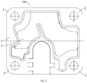
Fig. 2 illustrates a front view of a cylinder head according to embodiments of the present disclosure. -
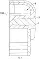
Fig. 3 illustrates a sectional view of a cylinder head according to embodiments of the present disclosure. -
Fig. 4 illustrates a top view of a piston compressor according to embodiments of the present disclosure. -
Fig. 5 illustrates an exploded view of a cylinder head and a valve assembly according to embodiments of the present disclosure. -
Fig. 6 illustrates a sectional view of a piston compressor according to embodiments of the present disclosure. -
-
cylinder head 100, - metal outer cover 1, mounting table 2, isolation
inner cover 3, accommodating chamber 4, -
cylinder block 101,piston 102, connectingrod 103,crankshaft 104,housing assembly 105,motor stator 106,motor rotor 107, -
lift limiter 200,exhaust valve sheet 300,valve plate 400,suction valve sheet 500. - Embodiments of the present disclosure will be described in detail and examples of the embodiments will be illustrated in the accompanying drawings, where same or similar reference numerals are used to indicate same or similar members or members with same or similar functions. The embodiments described herein with reference to the drawings are explanatory, which aim to illustrate the present disclosure, but shall not be construed to limit the present disclosure.
- A
cylinder head 100 for a piston compressor according to embodiments of the present disclosure will be described with reference toFigs. 1 to 6 . - As illustrated in
Figs. 1-6 , thecylinder head 100 according to the embodiments of the present disclosure includes a metal outer cover 1 and an isolationinner cover 3. - The metal outer cover 1 covers the isolation
inner cover 3, and the isolationinner cover 3 is made of a heat insulation material, that is, the isolationinner cover 3 has good heat insulation performance, such that the temperature of gas sucked by the compressor having thecylinder head 100 during operation will not be too high, hence providing the compressor with a stable cooling capacity and a high energy efficiency ratio. - As illustrated in
Fig. 3 , the metal outer cover 1 has a groove, and the isolationinner cover 3 is disposed to an inner wall surface of the groove to define an accommodating chamber 4, that is, an outer surface of the isolationinner cover 3 is fitted with the inner wall surface of the groove. In some embodiments, the isolationinner cover 3 is made of porous materials, so as to possess heat insulation, sound insulation, and vibration absorption effects. Thus, not only can the compressor have the stable cooling capacity and the high energy efficiency ratio, but also the isolationinner cover 3 can reduce the vibration impact on the cylinder head generated by the gas entering the accommodating chamber, attenuate the impact noise, and improve the vibration attenuation effect. In a specific embodiment shown inFig. 3 , the isolationinner cover 3 is made of a closed-cell foamed aluminum material, wherein the isolationinner cover 3 can be foamed and formed on the inner wall surface of the groove by a powder metallurgy foaming method in solid metal sintering methods. The isolationinner cover 3 can be foamed and formed into complex structures by the powder metallurgy foaming method to allow the isolationinner cover 3 to be closely fitted with the metal outer cover 1. - It should be noted that the closed-cell foamed aluminum material is a novel light functional material, and has characteristics of low density, high strength, high stiffness ratio, sound absorption, high damping and vibration attenuation performance, and high impact energy absorption rate. The density of the closed-cell foamed aluminum material is usually 0.1-0.4 times the density of metallic aluminum, such that it is appreciated that the isolation
inner cover 3 has a lightweight effect. Meanwhile, when the acoustic wave frequency is between 800 Hz and 4000 Hz, the sound insulation coefficient of the closed-cell foamed aluminum material is 0.9 or higher. The damping performance is 5-10 times that of metallic aluminum. Therefore, the isolationinner cover 3 made of the closed-cell foamed aluminum material has the advantages of light weight, excellent vibration absorption effect, good sound insulation effect, and good heat insulation performance. - As illustrated in
Figs. 4 and6 , thecylinder head 100 is mounted on the piston compressor, and the accommodating chamber 4 of the isolationinner cover 3 can be used to temporarily store the gas. Thecylinder head 100 is connected to a cylinder end of a crankcase by threaded fasteners, and at the same time the isolationinner cover 3 is partially in contact with a suction silencer. During the operation of the compressor, a refrigerant gas sucked through the suction silencer performs heat conduction with the refrigerant gas discharged from a cylinder bore into thecylinder head 100, and the refrigerant gas discharged into thecylinder head 100 may impact thecylinder head 100, thereby resulting in vibration and impact noise. However, the isolationinner cover 3 has good heat insulation performance, so that there is no excessive heat exchange between the discharged gas and the sucked gas. In such a way, the temperature of the sucked gas is not excessively high, thereby ensuring the stable cooling capacity of the compressor, and hence a refrigeration system with such a compressor has a relatively high energy efficiency ratio, improving the practicality and economy of the compressor, and avoiding suction overheating. Moreover, the isolationinner cover 3 has sound absorption and high damping characteristics which greatly reduce the impact noise and improve the vibration attenuation effect, so that the compressor has a stable working state during operation. - For the
cylinder head 100 according to the embodiments of the present disclosure, since the isolationinner cover 3 has good heat insulation and sound insulation performance, the temperature of the gas sucked by the compressor having thecylinder head 100 during operation is not too high, thereby ensuring a stable cooling capacity and a high energy efficiency ratio. The isolationinner cover 3 can reduce the vibration impact on thecylinder head 100 generated by the gas entering the accommodating chamber 4, weaken the impact noise, and improve the vibration attenuation effect. - For the
cylinder head 100 according to the embodiments of the present disclosure, as illustrated inFigs. 1 and2 , the metal outer cover 1 has a mounting table 2 configured to mount thecylinder head 100, and thecylinder head 100 can be fixedly connected to the cylinder end of the crankcase by threaded fasteners at the mounting table 2, whereby thecylinder head 100 can close the crankcase to facilitate the gas suction and discharge of the compressor. - In an embodiment, the metal outer cover 1 has four mounting tables 2 spaced apart along an axial direction. As shown in
Figs. 1 and2 , the four mounting tables 2 are located at four corners of the metal outer cover 1, such that four corners of thecylinder head 100 are fixedly connected with the cylinder end of the crankcase. A valve assembly is connected between thecylinder head 100 and the cylinder end of the crankcase, and includes alift limiter 200, anexhaust valve sheet 300, avalve plate 400, and asuction valve sheet 500. In this way, thecylinder head 100, thelift limiter 200, theexhaust valve sheet 300, thevalve plate 400, thesuction valve sheet 500, and the cylinder end of the crankcase are sequentially connected and fixed by multiple sets of threaded fasteners, thereby ensuring the normal gas suction and discharge of the compressor and improving the stability of the overall structure of the compressor. - In some embodiments, the isolation
inner cover 3 has a thickness of N, the metal outer cover 1 has a thickness of M, and the total thickness of thecylinder head 100 is H, which satisfy H=M+N, 0<N≤M. That is, the total thickness of thecylinder head 100 is equal to the sum of the thickness of the isolationinner cover 3 and the thickness of the metal outer cover 1, and the thickness of the metal outer cover 1 is not less than that of the isolationinner cover 3. Thus, the metal outer cover 1 of the thickness can ensure the high structural rigidity and strength of thecylinder head 100, and make the overall structure of thecylinder head 100 stable. At the same time, the isolationinner cover 3 of the corresponding thickness can avoid excessive heat conduction between the discharged gas and the sucked gas in thecylinder head 100, thereby ensuring that the suction temperature of the compressor is relatively low, and coupled with the sound insulation and high damping characteristics of the isolationinner cover 3, the noise reduction and silencing effect can be obtained, thereby upgrading the performance of the compressor. - In some embodiments, the closed cells of the isolation
inner cover 3 have a wall thickness of L, which satisfies 0.2mm≤L≤0.5mm. For example, L=0.3mm, and L=0.4mm. It is understood that the isolationinner cover 3 may be made of the closed-cell foamed aluminum material, that is, the isolationinner cover 3 has a plurality of closed cells, and a suitable wall thickness of the closed cells can ensure the rigidity and strength of the overall structure of the isolationinner cover 3, and guarantee that the isolationinner cover 3 has good sound insulation and heat insulation performance. The greater the wall thickness of the closed cells is, the poorer the heat insulation performance of the isolationinner cover 3 is, and materials are wasted. The smaller the wall thickness of the closed cells is, the lower the structural rigidity and strength of the isolationinner cover 3 is, and the isolationinner cover 3 is easily deformed. Thus, the isolationinner cover 3 of a suitable thickness can improve the overall performance efficiently and have excellent practicability and economy. - The isolation
inner cover 3 has an internal aperture of D which satisfies 1mm≤D≤6mm. For example, D=2mm, D=3mm, D=5mm. The internal aperture with suitable thickness can ensure that the isolationinner cover 3 has stable structural rigidity and good sound insulation and sound absorption performance. If the internal aperture is too large, the rigidity of the isolationinner cover 3 is poor and the stability will be reduced. If the internal aperture is too small, the sound insulation performance of the isolationinner cover 3 will become poor. Hence, the internal aperture is set to an appropriate size, which can effectively improve the overall performance. - The isolation
inner cover 3 has an internal porosity of A which satisfies 30%≤A≤75%. For example, A=40%, A=50%, A=60%. By setting a suitable internal porosity, it can be ensured that the isolationinner cover 3 has good sound insulation and heat insulation performance, and stable structural rigidity and strength, so that the isolationinner cover 3 can achieve the heat insulation effect on the gas suction and discharge, and lower the noise inside thecylinder head 100 effectively. - The isolation
inner cover 3 has an elasticity modulus of E which satisfies 1.4GPa≤E≤8.0GPa. For example, E=2.3GPa, E=4.2GPa, E=5.8GPa. By setting a suitable elasticity modulus, it can be ensured that the internal performance of the isolationinner cover 3 is stable, so that the overall structure of the isolationinner cover 3 is stable, avoiding excessive deformation of the isolationinner cover 3 under external forces, and improving the stability of the overall structure of thecylinder head 100. Moreover, the isolationinner cover 3 with a higher elasticity modulus can have better vibration damping performance, absorb the impact energy of the gas on thecylinder head 100, and reduce noise. - The isolation
inner cover 3 has a silicon carbide additive, and the mass fraction of silicon carbide contained therein is B, which satisfies 0.1%≤B≤1.1%. For example, B=0.4%, B=0.7%, B=1.0%. By adding silicon carbide to the isolationinner cover 3, the rigidity and strength of the isolationinner cover 3 can be improved to provide excellent stability of the isolationinner cover 3. - The present disclosure further proposes a piston compressor.
- The piston compressor according to embodiments of the present disclosure is provided with the
cylinder head 100 according to any one of the above embodiments. The isolationinner cover 3 has good heat insulation and sound insulation performance, so that the temperature of the gas sucked by the piston compressor during operation will not be too high, thereby ensuring a stable cooling capacity and higher energy efficiency ratio. Moreover, the isolationinner cover 3 can reduce the vibration impact on thecylinder head 100, generated by the gas entering the accommodating chamber 4, weaken the impact noise, and improve the vibration attenuation effect. - As illustrated in
Fig. 6 , the piston compressor further includes acylinder block 101, apiston 102, a connectingrod 103, acrankshaft 104, ahousing assembly 105, amotor stator 106, and amotor rotor 107. A driving motor drives thecrankshaft 104 to move, thecrankshaft 104 drives the connectingrod 103 to move, the connectingrod 103 drives, by a piston pin, thepiston 102 to reciprocate, thereby realizing the gas suction and discharge of the compressor. Thecylinder block 101, thepiston 102, the connectingrod 103, thecrankshaft 104, themotor stator 106, and themotor rotor 107 are all mounted in thehousing assembly 105 to make various components of the piston compressor relatively fixed, and to create a stable working environment. - It should be noted that the piston compressor according to the embodiments of the present disclosure can be applied to any refrigeration device such as a refrigerator, a freezer, an air conditioner, a dehumidifier and so on, and where the piston compressor is connected to an evaporator, a condenser, a throttle device and the like to constitute a complete refrigeration system. Such a refrigeration system would be provided with good cooling performance and low noise in use.
- Reference throughout this specification to "an embodiment," "some embodiments," "an exemplary embodiment," "an example," "a specific example," or "some examples," means that a particular feature, structure, material, or characteristic described in connection with the embodiment or example is included in at least one embodiment or example of the present disclosure. The appearances of the above phrases throughout this specification are not necessarily referring to the same embodiment or example of the present disclosure. Furthermore, the particular features, structures, materials, or characteristics may be combined in any suitable manner in one or more embodiments or examples.
- Although embodiments of the present disclosure have been shown and described, it would be appreciated by those skilled in the art that any changes, modifications, alternatives and variations can be made in the embodiments without departing from the principle and purpose of the present disclosure.
Claims (10)
- A cylinder head (100) for a piston (102) compressor, comprising: a metal outer cover and an isolation inner cover (3), the metal outer cover covering the isolation inner cover (3), and the isolation inner cover (3) being made of a heat insulation material, characterized in that the isolation inner cover (3) is made of a closed-cell foamed aluminum material; and wherein the isolation inner cover (3) has a silicon carbide additive, and the contained silicon carbide has a mass fraction of B which satisfies 0.1%≤B≤1.1%.
- The cylinder head (100) according to any preceding claim, wherein the metal outer cover has a groove, and the isolation inner cover (3) is disposed to an inner wall surface of the groove to define an accommodating chamber (4).
- The cylinder head (100) according to any preceding claim, wherein the metal outer cover is made of a solid aluminum material.
- The cylinder head (100) according to any preceding claim, wherein the metal outer cover has a mounting table (2) configured to mount the cylinder head (100).
- The cylinder head (100) according to any preceding claim, wherein the isolation inner cover (3) has a thickness of N, and the metal outer cover has a thickness of M, which satisfy 0<N≤ M.
- The cylinder head (100) according to any preceding claim, wherein a closed cell of the isolation inner cover (3) has a wall thickness of L which satisfies 0.2mm≤L≤0.5mm.
- The cylinder head (100) according to any preceding claim, wherein the isolation inner cover (3) has an internal aperture of D which satisfies 1mm≤D≤6mm.
- The cylinder head (100) according to any preceding claim, wherein the isolation inner cover (3) has an internal porosity of A which satisfies 30%≤A≤75%.
- The cylinder head (100) according to claim 5, wherein the isolation inner cover (3) has an elasticity modulus of E which satisfies 1.4GPa≤E≤8.0GPa.
- A piston (102) compressor provided with the cylinder head (100) for a piston (102) compressor according to any one of claims 1 to 9.
Applications Claiming Priority (2)
| Application Number | Priority Date | Filing Date | Title |
|---|---|---|---|
| CN201810714128.2A CN110657086A (en) | 2018-06-29 | 2018-06-29 | Cylinder cover of piston compressor and piston compressor |
| PCT/CN2018/098940 WO2020000584A1 (en) | 2018-06-29 | 2018-08-06 | Cylinder head of piston type compressor and piston type compressor |
Publications (3)
| Publication Number | Publication Date |
|---|---|
| EP3617515A1 EP3617515A1 (en) | 2020-03-04 |
| EP3617515A4 EP3617515A4 (en) | 2020-08-12 |
| EP3617515B1 true EP3617515B1 (en) | 2021-05-12 |
Family
ID=68985722
Family Applications (1)
| Application Number | Title | Priority Date | Filing Date |
|---|---|---|---|
| EP18919391.5A Active EP3617515B1 (en) | 2018-06-29 | 2018-08-06 | Cylinder head of piston type compressor and piston type compressor |
Country Status (4)
| Country | Link |
|---|---|
| EP (1) | EP3617515B1 (en) |
| JP (1) | JP2020528508A (en) |
| CN (1) | CN110657086A (en) |
| WO (1) | WO2020000584A1 (en) |
Families Citing this family (3)
| Publication number | Priority date | Publication date | Assignee | Title |
|---|---|---|---|---|
| KR102430410B1 (en) | 2020-12-02 | 2022-08-09 | 엘지전자 주식회사 | Linear compressor |
| CN116163924B (en) * | 2022-02-18 | 2026-03-03 | 安徽美芝制冷设备有限公司 | Compressor and refrigeration equipment |
| CN116147452B (en) * | 2022-12-05 | 2025-07-25 | 青岛万宝压缩机有限公司 | Compressor exhaust valve plate lift measuring method, valve plate assembly and compressor |
Family Cites Families (22)
| Publication number | Priority date | Publication date | Assignee | Title |
|---|---|---|---|---|
| US5112697A (en) * | 1989-09-06 | 1992-05-12 | Alcan International Limited | Stabilized metal foam body |
| DE19839536A1 (en) * | 1997-08-29 | 1999-03-04 | Luk Fahrzeug Hydraulik | Compressor for air conditioning unit of a motor vehicle |
| JP2002235667A (en) * | 2001-02-08 | 2002-08-23 | Sanyo Electric Co Ltd | Refrigerant compressor |
| DE10326912A1 (en) * | 2002-06-17 | 2003-12-24 | Martin Raes | Block-heating power generation unit, in particular in the form of a small unit with a motor-generator set and a heat exchanger is enclosed in a sound-insulating cover without any parallel side walls |
| US7398855B2 (en) * | 2004-05-14 | 2008-07-15 | Emerson Climate Technologies, Inc. | Compressor sound attenuation enclosure |
| JP4189401B2 (en) * | 2005-10-05 | 2008-12-03 | 本田技研工業株式会社 | Method for producing foamed aluminum |
| SG141266A1 (en) * | 2006-09-12 | 2008-04-28 | Matsushita Electric Industrial Co Ltd | A compressor structure for a refrigeration system |
| JP2010053784A (en) * | 2008-08-28 | 2010-03-11 | Toyota Industries Corp | Compressor |
| JP2011196244A (en) * | 2010-03-19 | 2011-10-06 | Panasonic Corp | Compressor |
| JP2012145051A (en) * | 2011-01-13 | 2012-08-02 | Daikin Industries Ltd | Compressor |
| BRPI1103666A2 (en) * | 2011-07-08 | 2013-07-16 | Whirlpool Sa | set of fluid compressor head and process of making set of fluid compressor head |
| CN102562298A (en) * | 2012-02-13 | 2012-07-11 | 陈名辉 | Heat-insulation internal cooling engine |
| JP2014114760A (en) * | 2012-12-11 | 2014-06-26 | Panasonic Corp | Cooling medium compressor and refrigeration device using the same |
| CN203301294U (en) * | 2013-04-25 | 2013-11-20 | 王强 | Sound-absorbing noise reduction apparatus |
| SI3017194T1 (en) * | 2013-07-04 | 2017-06-30 | Arcelik Anonim Sirketi | Thermally improved reciprocating hermetic compressor |
| CN203822465U (en) * | 2014-03-27 | 2014-09-10 | 潍柴动力股份有限公司 | Soundproof hood of engine |
| KR101558381B1 (en) * | 2014-04-18 | 2015-10-07 | 현대자동차 주식회사 | Cylinder head for engine |
| DE102014111527B4 (en) * | 2014-08-13 | 2018-05-09 | Knorr-Bremse Systeme für Nutzfahrzeuge GmbH | Cylinder head for a compressor with particularly efficient air cooling |
| CN104478337B (en) * | 2014-12-17 | 2016-05-11 | 南京理工大学常熟研究院有限公司 | A kind of foamed aluminium material |
| CN106351843A (en) * | 2016-10-17 | 2017-01-25 | 西安交通大学 | Downward exhaust heat-resistant rotary compressor |
| CN107387417B (en) * | 2017-07-31 | 2021-08-31 | 广东美芝制冷设备有限公司 | Double-layer compressor and installation method thereof |
| CN207363728U (en) * | 2017-10-20 | 2018-05-15 | 嘉峪关天源新材料有限责任公司 | Diesel engine oil pan with vibration and noise reduction |
-
2018
- 2018-06-29 CN CN201810714128.2A patent/CN110657086A/en active Pending
- 2018-08-06 WO PCT/CN2018/098940 patent/WO2020000584A1/en not_active Ceased
- 2018-08-06 EP EP18919391.5A patent/EP3617515B1/en active Active
- 2018-08-06 JP JP2019561155A patent/JP2020528508A/en active Pending
Also Published As
| Publication number | Publication date |
|---|---|
| EP3617515A1 (en) | 2020-03-04 |
| EP3617515A4 (en) | 2020-08-12 |
| JP2020528508A (en) | 2020-09-24 |
| WO2020000584A1 (en) | 2020-01-02 |
| CN110657086A (en) | 2020-01-07 |
Similar Documents
| Publication | Publication Date | Title |
|---|---|---|
| EP3617515A1 (en) | Cylinder head of piston type compressor and piston type compressor | |
| EP2725228B1 (en) | Discrete heat-insulated exhaust muffler device and refrigeration compressor using same | |
| GB2136511A (en) | Muffler system for refrigeration compressor | |
| CN113915129B (en) | Low pressure chamber rotary compressor and air conditioner | |
| KR20210149198A (en) | Baffle plates used in compressors, compressors and air conditioners | |
| CN213981103U (en) | Air compressor machine shell of making an uproar falls in heat dissipation | |
| CN212867918U (en) | Compressor structure and air conditioner with same | |
| CN114017344B (en) | Rotary compressor and refrigeration equipment | |
| CN212079648U (en) | Refrigerator with low-noise compressor | |
| CN221103740U (en) | Electric compressor variable frequency controller with low noise | |
| CN216241308U (en) | Rotor assemblies and compressors | |
| CN214366728U (en) | Permanent magnet integrated air compressor with oil cooling function | |
| CN114033697A (en) | Stopper, compressor and refrigeration plant | |
| WO2019129432A1 (en) | A hermetic compressor | |
| CN222703480U (en) | Middle partition plate assembly and air source heat pump air conditioner | |
| CN221033025U (en) | Noise reduction shell structure of oil-free compressor | |
| CN222910206U (en) | Compressor assembly, air conditioning system and vehicle | |
| CN223089486U (en) | A flat compressor body | |
| CN220302298U (en) | Heat abstractor for be used for air compressor | |
| CN113775524B (en) | Two-stage compression screw compressor shell with noise reduction function | |
| RU2115007C1 (en) | Oil sump of internal combustion engine | |
| RU2115006C1 (en) | Oil sump of internal combustion engine | |
| CN223923225U (en) | Bearing assembly, compressor and refrigeration equipment | |
| CN223411331U (en) | Damping rubber ring and damping motor | |
| CN215058012U (en) | Cooling device for compressor |
Legal Events
| Date | Code | Title | Description |
|---|---|---|---|
| STAA | Information on the status of an ep patent application or granted ep patent |
Free format text: STATUS: UNKNOWN |
|
| STAA | Information on the status of an ep patent application or granted ep patent |
Free format text: STATUS: THE INTERNATIONAL PUBLICATION HAS BEEN MADE |
|
| PUAI | Public reference made under article 153(3) epc to a published international application that has entered the european phase |
Free format text: ORIGINAL CODE: 0009012 |
|
| STAA | Information on the status of an ep patent application or granted ep patent |
Free format text: STATUS: REQUEST FOR EXAMINATION WAS MADE |
|
| 17P | Request for examination filed |
Effective date: 20191126 |
|
| AK | Designated contracting states |
Kind code of ref document: A1 Designated state(s): AL AT BE BG CH CY CZ DE DK EE ES FI FR GB GR HR HU IE IS IT LI LT LU LV MC MK MT NL NO PL PT RO RS SE SI SK SM TR |
|
| AX | Request for extension of the european patent |
Extension state: BA ME |
|
| A4 | Supplementary search report drawn up and despatched |
Effective date: 20200710 |
|
| RIC1 | Information provided on ipc code assigned before grant |
Ipc: F04C 29/06 20060101AFI20200706BHEP Ipc: F04B 39/06 20060101ALI20200706BHEP Ipc: F04B 39/12 20060101ALI20200706BHEP |
|
| GRAP | Despatch of communication of intention to grant a patent |
Free format text: ORIGINAL CODE: EPIDOSNIGR1 |
|
| STAA | Information on the status of an ep patent application or granted ep patent |
Free format text: STATUS: GRANT OF PATENT IS INTENDED |
|
| RIC1 | Information provided on ipc code assigned before grant |
Ipc: F04C 29/06 20060101AFI20210129BHEP Ipc: F04B 39/12 20060101ALI20210129BHEP Ipc: F04B 39/06 20060101ALI20210129BHEP |
|
| DAV | Request for validation of the european patent (deleted) | ||
| DAX | Request for extension of the european patent (deleted) | ||
| INTG | Intention to grant announced |
Effective date: 20210215 |
|
| GRAS | Grant fee paid |
Free format text: ORIGINAL CODE: EPIDOSNIGR3 |
|
| GRAA | (expected) grant |
Free format text: ORIGINAL CODE: 0009210 |
|
| STAA | Information on the status of an ep patent application or granted ep patent |
Free format text: STATUS: THE PATENT HAS BEEN GRANTED |
|
| AK | Designated contracting states |
Kind code of ref document: B1 Designated state(s): AL AT BE BG CH CY CZ DE DK EE ES FI FR GB GR HR HU IE IS IT LI LT LU LV MC MK MT NL NO PL PT RO RS SE SI SK SM TR |
|
| REG | Reference to a national code |
Ref country code: GB Ref legal event code: FG4D |
|
| REG | Reference to a national code |
Ref country code: CH Ref legal event code: EP |
|
| REG | Reference to a national code |
Ref country code: DE Ref legal event code: R096 Ref document number: 602018017128 Country of ref document: DE |
|
| REG | Reference to a national code |
Ref country code: IE Ref legal event code: FG4D |
|
| REG | Reference to a national code |
Ref country code: AT Ref legal event code: REF Ref document number: 1392357 Country of ref document: AT Kind code of ref document: T Effective date: 20210615 |
|
| REG | Reference to a national code |
Ref country code: LT Ref legal event code: MG9D |
|
| REG | Reference to a national code |
Ref country code: NL Ref legal event code: MP Effective date: 20210512 |
|
| PG25 | Lapsed in a contracting state [announced via postgrant information from national office to epo] |
Ref country code: BG Free format text: LAPSE BECAUSE OF FAILURE TO SUBMIT A TRANSLATION OF THE DESCRIPTION OR TO PAY THE FEE WITHIN THE PRESCRIBED TIME-LIMIT Effective date: 20210812 Ref country code: FI Free format text: LAPSE BECAUSE OF FAILURE TO SUBMIT A TRANSLATION OF THE DESCRIPTION OR TO PAY THE FEE WITHIN THE PRESCRIBED TIME-LIMIT Effective date: 20210512 Ref country code: LT Free format text: LAPSE BECAUSE OF FAILURE TO SUBMIT A TRANSLATION OF THE DESCRIPTION OR TO PAY THE FEE WITHIN THE PRESCRIBED TIME-LIMIT Effective date: 20210512 Ref country code: HR Free format text: LAPSE BECAUSE OF FAILURE TO SUBMIT A TRANSLATION OF THE DESCRIPTION OR TO PAY THE FEE WITHIN THE PRESCRIBED TIME-LIMIT Effective date: 20210512 |
|
| PG25 | Lapsed in a contracting state [announced via postgrant information from national office to epo] |
Ref country code: GR Free format text: LAPSE BECAUSE OF FAILURE TO SUBMIT A TRANSLATION OF THE DESCRIPTION OR TO PAY THE FEE WITHIN THE PRESCRIBED TIME-LIMIT Effective date: 20210813 Ref country code: IS Free format text: LAPSE BECAUSE OF FAILURE TO SUBMIT A TRANSLATION OF THE DESCRIPTION OR TO PAY THE FEE WITHIN THE PRESCRIBED TIME-LIMIT Effective date: 20210912 Ref country code: PT Free format text: LAPSE BECAUSE OF FAILURE TO SUBMIT A TRANSLATION OF THE DESCRIPTION OR TO PAY THE FEE WITHIN THE PRESCRIBED TIME-LIMIT Effective date: 20210913 Ref country code: SE Free format text: LAPSE BECAUSE OF FAILURE TO SUBMIT A TRANSLATION OF THE DESCRIPTION OR TO PAY THE FEE WITHIN THE PRESCRIBED TIME-LIMIT Effective date: 20210512 Ref country code: RS Free format text: LAPSE BECAUSE OF FAILURE TO SUBMIT A TRANSLATION OF THE DESCRIPTION OR TO PAY THE FEE WITHIN THE PRESCRIBED TIME-LIMIT Effective date: 20210512 Ref country code: PL Free format text: LAPSE BECAUSE OF FAILURE TO SUBMIT A TRANSLATION OF THE DESCRIPTION OR TO PAY THE FEE WITHIN THE PRESCRIBED TIME-LIMIT Effective date: 20210512 Ref country code: LV Free format text: LAPSE BECAUSE OF FAILURE TO SUBMIT A TRANSLATION OF THE DESCRIPTION OR TO PAY THE FEE WITHIN THE PRESCRIBED TIME-LIMIT Effective date: 20210512 Ref country code: NO Free format text: LAPSE BECAUSE OF FAILURE TO SUBMIT A TRANSLATION OF THE DESCRIPTION OR TO PAY THE FEE WITHIN THE PRESCRIBED TIME-LIMIT Effective date: 20210812 |
|
| PG25 | Lapsed in a contracting state [announced via postgrant information from national office to epo] |
Ref country code: NL Free format text: LAPSE BECAUSE OF FAILURE TO SUBMIT A TRANSLATION OF THE DESCRIPTION OR TO PAY THE FEE WITHIN THE PRESCRIBED TIME-LIMIT Effective date: 20210512 |
|
| PG25 | Lapsed in a contracting state [announced via postgrant information from national office to epo] |
Ref country code: SK Free format text: LAPSE BECAUSE OF FAILURE TO SUBMIT A TRANSLATION OF THE DESCRIPTION OR TO PAY THE FEE WITHIN THE PRESCRIBED TIME-LIMIT Effective date: 20210512 Ref country code: EE Free format text: LAPSE BECAUSE OF FAILURE TO SUBMIT A TRANSLATION OF THE DESCRIPTION OR TO PAY THE FEE WITHIN THE PRESCRIBED TIME-LIMIT Effective date: 20210512 Ref country code: ES Free format text: LAPSE BECAUSE OF FAILURE TO SUBMIT A TRANSLATION OF THE DESCRIPTION OR TO PAY THE FEE WITHIN THE PRESCRIBED TIME-LIMIT Effective date: 20210512 Ref country code: DK Free format text: LAPSE BECAUSE OF FAILURE TO SUBMIT A TRANSLATION OF THE DESCRIPTION OR TO PAY THE FEE WITHIN THE PRESCRIBED TIME-LIMIT Effective date: 20210512 Ref country code: CZ Free format text: LAPSE BECAUSE OF FAILURE TO SUBMIT A TRANSLATION OF THE DESCRIPTION OR TO PAY THE FEE WITHIN THE PRESCRIBED TIME-LIMIT Effective date: 20210512 Ref country code: RO Free format text: LAPSE BECAUSE OF FAILURE TO SUBMIT A TRANSLATION OF THE DESCRIPTION OR TO PAY THE FEE WITHIN THE PRESCRIBED TIME-LIMIT Effective date: 20210512 Ref country code: SM Free format text: LAPSE BECAUSE OF FAILURE TO SUBMIT A TRANSLATION OF THE DESCRIPTION OR TO PAY THE FEE WITHIN THE PRESCRIBED TIME-LIMIT Effective date: 20210512 |
|
| REG | Reference to a national code |
Ref country code: DE Ref legal event code: R097 Ref document number: 602018017128 Country of ref document: DE |
|
| PLBE | No opposition filed within time limit |
Free format text: ORIGINAL CODE: 0009261 |
|
| STAA | Information on the status of an ep patent application or granted ep patent |
Free format text: STATUS: NO OPPOSITION FILED WITHIN TIME LIMIT |
|
| REG | Reference to a national code |
Ref country code: CH Ref legal event code: PL |
|
| PG25 | Lapsed in a contracting state [announced via postgrant information from national office to epo] |
Ref country code: MC Free format text: LAPSE BECAUSE OF FAILURE TO SUBMIT A TRANSLATION OF THE DESCRIPTION OR TO PAY THE FEE WITHIN THE PRESCRIBED TIME-LIMIT Effective date: 20210512 |
|
| 26N | No opposition filed |
Effective date: 20220215 |
|
| REG | Reference to a national code |
Ref country code: BE Ref legal event code: MM Effective date: 20210831 |
|
| PG25 | Lapsed in a contracting state [announced via postgrant information from national office to epo] |
Ref country code: LI Free format text: LAPSE BECAUSE OF NON-PAYMENT OF DUE FEES Effective date: 20210831 Ref country code: CH Free format text: LAPSE BECAUSE OF NON-PAYMENT OF DUE FEES Effective date: 20210831 |
|
| PG25 | Lapsed in a contracting state [announced via postgrant information from national office to epo] |
Ref country code: IS Free format text: LAPSE BECAUSE OF FAILURE TO SUBMIT A TRANSLATION OF THE DESCRIPTION OR TO PAY THE FEE WITHIN THE PRESCRIBED TIME-LIMIT Effective date: 20210912 Ref country code: LU Free format text: LAPSE BECAUSE OF NON-PAYMENT OF DUE FEES Effective date: 20210806 Ref country code: AL Free format text: LAPSE BECAUSE OF FAILURE TO SUBMIT A TRANSLATION OF THE DESCRIPTION OR TO PAY THE FEE WITHIN THE PRESCRIBED TIME-LIMIT Effective date: 20210512 |
|
| PG25 | Lapsed in a contracting state [announced via postgrant information from national office to epo] |
Ref country code: IT Free format text: LAPSE BECAUSE OF FAILURE TO SUBMIT A TRANSLATION OF THE DESCRIPTION OR TO PAY THE FEE WITHIN THE PRESCRIBED TIME-LIMIT Effective date: 20210512 Ref country code: IE Free format text: LAPSE BECAUSE OF NON-PAYMENT OF DUE FEES Effective date: 20210806 Ref country code: FR Free format text: LAPSE BECAUSE OF NON-PAYMENT OF DUE FEES Effective date: 20210831 Ref country code: BE Free format text: LAPSE BECAUSE OF NON-PAYMENT OF DUE FEES Effective date: 20210831 |
|
| REG | Reference to a national code |
Ref country code: AT Ref legal event code: UEP Ref document number: 1392357 Country of ref document: AT Kind code of ref document: T Effective date: 20210512 |
|
| GBPC | Gb: european patent ceased through non-payment of renewal fee |
Effective date: 20220806 |
|
| PG25 | Lapsed in a contracting state [announced via postgrant information from national office to epo] |
Ref country code: CY Free format text: LAPSE BECAUSE OF FAILURE TO SUBMIT A TRANSLATION OF THE DESCRIPTION OR TO PAY THE FEE WITHIN THE PRESCRIBED TIME-LIMIT Effective date: 20210512 |
|
| PG25 | Lapsed in a contracting state [announced via postgrant information from national office to epo] |
Ref country code: HU Free format text: LAPSE BECAUSE OF FAILURE TO SUBMIT A TRANSLATION OF THE DESCRIPTION OR TO PAY THE FEE WITHIN THE PRESCRIBED TIME-LIMIT; INVALID AB INITIO Effective date: 20180806 |
|
| PG25 | Lapsed in a contracting state [announced via postgrant information from national office to epo] |
Ref country code: GB Free format text: LAPSE BECAUSE OF NON-PAYMENT OF DUE FEES Effective date: 20220806 |
|
| PG25 | Lapsed in a contracting state [announced via postgrant information from national office to epo] |
Ref country code: MK Free format text: LAPSE BECAUSE OF FAILURE TO SUBMIT A TRANSLATION OF THE DESCRIPTION OR TO PAY THE FEE WITHIN THE PRESCRIBED TIME-LIMIT Effective date: 20210512 |
|
| PG25 | Lapsed in a contracting state [announced via postgrant information from national office to epo] |
Ref country code: TR Free format text: LAPSE BECAUSE OF FAILURE TO SUBMIT A TRANSLATION OF THE DESCRIPTION OR TO PAY THE FEE WITHIN THE PRESCRIBED TIME-LIMIT Effective date: 20210512 |
|
| PG25 | Lapsed in a contracting state [announced via postgrant information from national office to epo] |
Ref country code: MT Free format text: LAPSE BECAUSE OF FAILURE TO SUBMIT A TRANSLATION OF THE DESCRIPTION OR TO PAY THE FEE WITHIN THE PRESCRIBED TIME-LIMIT Effective date: 20210512 |
|
| PGFP | Annual fee paid to national office [announced via postgrant information from national office to epo] |
Ref country code: DE Payment date: 20250827 Year of fee payment: 8 |
|
| PGFP | Annual fee paid to national office [announced via postgrant information from national office to epo] |
Ref country code: AT Payment date: 20250819 Year of fee payment: 8 |