EP3616377B1 - Übertragung von uplink kontrolinformation (uci) - Google Patents
Übertragung von uplink kontrolinformation (uci) Download PDFInfo
- Publication number
- EP3616377B1 EP3616377B1 EP18726594.7A EP18726594A EP3616377B1 EP 3616377 B1 EP3616377 B1 EP 3616377B1 EP 18726594 A EP18726594 A EP 18726594A EP 3616377 B1 EP3616377 B1 EP 3616377B1
- Authority
- EP
- European Patent Office
- Prior art keywords
- dmrs
- sequence
- uci
- pilot sub
- dmrs sequence
- Prior art date
- Legal status (The legal status is an assumption and is not a legal conclusion. Google has not performed a legal analysis and makes no representation as to the accuracy of the status listed.)
- Active
Links
- 238000004891 communication Methods 0.000 claims description 54
- 238000000034 method Methods 0.000 claims description 47
- 101000741965 Homo sapiens Inactive tyrosine-protein kinase PRAG1 Proteins 0.000 claims 2
- 102100038659 Inactive tyrosine-protein kinase PRAG1 Human genes 0.000 claims 2
- 230000005540 biological transmission Effects 0.000 description 84
- 230000006870 function Effects 0.000 description 51
- 230000008569 process Effects 0.000 description 21
- 238000012545 processing Methods 0.000 description 15
- 230000004044 response Effects 0.000 description 10
- 238000005516 engineering process Methods 0.000 description 7
- 238000010586 diagram Methods 0.000 description 6
- 238000012913 prioritisation Methods 0.000 description 6
- 238000013461 design Methods 0.000 description 5
- 239000000969 carrier Substances 0.000 description 3
- 230000001413 cellular effect Effects 0.000 description 3
- 125000004122 cyclic group Chemical group 0.000 description 3
- 238000007726 management method Methods 0.000 description 3
- 241000760358 Enodes Species 0.000 description 2
- 238000003491 array Methods 0.000 description 2
- 230000009286 beneficial effect Effects 0.000 description 2
- 230000008859 change Effects 0.000 description 2
- 238000004590 computer program Methods 0.000 description 2
- 230000036541 health Effects 0.000 description 2
- 238000010295 mobile communication Methods 0.000 description 2
- 230000008901 benefit Effects 0.000 description 1
- 239000003795 chemical substances by application Substances 0.000 description 1
- 230000001427 coherent effect Effects 0.000 description 1
- 239000004020 conductor Substances 0.000 description 1
- 230000008878 coupling Effects 0.000 description 1
- 238000010168 coupling process Methods 0.000 description 1
- 238000005859 coupling reaction Methods 0.000 description 1
- 230000007123 defense Effects 0.000 description 1
- 238000001514 detection method Methods 0.000 description 1
- 239000003814 drug Substances 0.000 description 1
- 230000000977 initiatory effect Effects 0.000 description 1
- 238000002955 isolation Methods 0.000 description 1
- 230000007774 longterm Effects 0.000 description 1
- 239000011159 matrix material Substances 0.000 description 1
- 230000007246 mechanism Effects 0.000 description 1
- 238000012806 monitoring device Methods 0.000 description 1
- 230000003287 optical effect Effects 0.000 description 1
- 230000008520 organization Effects 0.000 description 1
- 239000005022 packaging material Substances 0.000 description 1
- 238000004806 packaging method and process Methods 0.000 description 1
- 230000002093 peripheral effect Effects 0.000 description 1
- 238000012163 sequencing technique Methods 0.000 description 1
- 230000011664 signaling Effects 0.000 description 1
- 238000004513 sizing Methods 0.000 description 1
- 238000001228 spectrum Methods 0.000 description 1
- 238000012546 transfer Methods 0.000 description 1
- XLYOFNOQVPJJNP-UHFFFAOYSA-N water Substances O XLYOFNOQVPJJNP-UHFFFAOYSA-N 0.000 description 1
Images


Classifications
-
- H—ELECTRICITY
- H04—ELECTRIC COMMUNICATION TECHNIQUE
- H04L—TRANSMISSION OF DIGITAL INFORMATION, e.g. TELEGRAPHIC COMMUNICATION
- H04L5/00—Arrangements affording multiple use of the transmission path
- H04L5/003—Arrangements for allocating sub-channels of the transmission path
- H04L5/0048—Allocation of pilot signals, i.e. of signals known to the receiver
- H04L5/0051—Allocation of pilot signals, i.e. of signals known to the receiver of dedicated pilots, i.e. pilots destined for a single user or terminal
-
- H—ELECTRICITY
- H04—ELECTRIC COMMUNICATION TECHNIQUE
- H04L—TRANSMISSION OF DIGITAL INFORMATION, e.g. TELEGRAPHIC COMMUNICATION
- H04L5/00—Arrangements affording multiple use of the transmission path
- H04L5/003—Arrangements for allocating sub-channels of the transmission path
- H04L5/0048—Allocation of pilot signals, i.e. of signals known to the receiver
-
- H—ELECTRICITY
- H04—ELECTRIC COMMUNICATION TECHNIQUE
- H04L—TRANSMISSION OF DIGITAL INFORMATION, e.g. TELEGRAPHIC COMMUNICATION
- H04L27/00—Modulated-carrier systems
- H04L27/26—Systems using multi-frequency codes
- H04L27/2601—Multicarrier modulation systems
- H04L27/2602—Signal structure
- H04L27/261—Details of reference signals
- H04L27/2613—Structure of the reference signals
- H04L27/26136—Pilot sequence conveying additional information
-
- H—ELECTRICITY
- H04—ELECTRIC COMMUNICATION TECHNIQUE
- H04L—TRANSMISSION OF DIGITAL INFORMATION, e.g. TELEGRAPHIC COMMUNICATION
- H04L5/00—Arrangements affording multiple use of the transmission path
- H04L5/003—Arrangements for allocating sub-channels of the transmission path
- H04L5/0044—Arrangements for allocating sub-channels of the transmission path allocation of payload
-
- H—ELECTRICITY
- H04—ELECTRIC COMMUNICATION TECHNIQUE
- H04L—TRANSMISSION OF DIGITAL INFORMATION, e.g. TELEGRAPHIC COMMUNICATION
- H04L5/00—Arrangements affording multiple use of the transmission path
- H04L5/003—Arrangements for allocating sub-channels of the transmission path
- H04L5/0053—Allocation of signaling, i.e. of overhead other than pilot signals
-
- H—ELECTRICITY
- H04—ELECTRIC COMMUNICATION TECHNIQUE
- H04W—WIRELESS COMMUNICATION NETWORKS
- H04W72/00—Local resource management
- H04W72/20—Control channels or signalling for resource management
- H04W72/21—Control channels or signalling for resource management in the uplink direction of a wireless link, i.e. towards the network
Definitions
- the technology discussed below relates generally to wireless communication systems, and more particularly, to systems and methods for transmitting uplink control information (UCI).
- UCI uplink control information
- Wireless communications from an uplink (UL) standpoint typically use a demodulation reference signal (DMRS) sequence known by a base station for channel estimation to demodulate received data.
- DMRS demodulation reference signal
- WO 2017/038337 A1 relates to a radio terminal and a base station used in a mobile communication system.
- the DMRS sequence typically does not convey information from higher layers.
- multiple uses can be assigned to certain aspects of wireless communication to advance and enhance the user experience with mobile communications.
- Implementations may range a spectrum from chip-level or modular components to non-modular, non-chip-level implementations and further to aggregate, distributed, or original equipment manufacturer (OEM) devices or systems incorporating one or more aspects of the described innovations.
- devices incorporating described aspects and features may also necessarily include additional components and features for implementation and practice of claimed and described embodiments.
- transmission and reception of wireless signals necessarily includes a number of components for analog and digital purposes (e.g., hardware components including antenna, radio frequency (RF) chains, power amplifiers, modulators, buffer, processor(s), interleaver, adders/summers, etc.).
- RF radio frequency
- innovations described herein may be practiced in a wide variety of devices, chip-level components, systems, distributed arrangements, end-user devices, etc. of varying sizes, shapes and constitution.
- the various concepts presented throughout this disclosure may be implemented across a broad variety of telecommunication systems, network architectures, and communication standards.
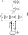
- the wireless communication system 100 includes three interacting domains: a core network 102, a radio access network (RAN) 104, and a user equipment (UE) 106.
- the UE 106 may be enabled to carry out data communication with an external data network 110, such as (but not limited to) the Internet.
- the RAN 104 may implement any suitable wireless communication technology or technologies to provide radio access to the UE 106.
- the RAN 104 may operate according to 3 rd Generation Partnership Project (3GPP) New Radio (NR) specifications, often referred to as 5G.
- 3GPP 3 rd Generation Partnership Project
- NR New Radio
- the RAN 104 may operate under a hybrid of 5G NR and Evolved Universal Terrestrial Radio Access Network (eUTRAN) standards, often referred to as LTE.
- eUTRAN Evolved Universal Terrestrial Radio Access Network
- the 3GPP refers to this hybrid RAN as a next-generation RAN, or NG-RAN.
- a base station is a network element in a radio access network responsible for radio transmission and reception in one or more cells to or from a UE.
- a base station may variously be referred to by those skilled in the art as a base transceiver station (BTS), a radio base station, a radio transceiver, a transceiver function, a basic service set (BSS), an extended service set (ESS), an access point (AP), a Node B (NB), an eNode B (eNB), a gNode B (gNB), or some other suitable terminology.
- BTS base transceiver station
- BSS basic service set
- ESS extended service set
- AP access point
- NB Node B
- eNB eNode B
- gNB gNode B
- the RAN 104 is further illustrated supporting wireless communication for multiple mobile apparatuses.
- a mobile apparatus may be referred to as user equipment (UE) in 3GPP standards, but may also be referred to by those skilled in the art as a mobile station (MS), a subscriber station, a mobile unit, a subscriber unit, a wireless unit, a remote unit, a mobile device, a wireless device, a wireless communications device, a remote device, a mobile subscriber station, an access terminal (AT), a mobile terminal, a wireless terminal, a remote terminal, a handset, a terminal, a user agent, a mobile client, a client, or some other suitable terminology.
- a UE may be an apparatus that provides a user with access to network services.
- a "mobile” apparatus need not necessarily have a capability to move, and may be stationary.
- the term mobile apparatus or mobile device broadly refers to a diverse array of devices and technologies.
- UEs may include a number of hardware structural components sized, shaped, and arranged to help in communication; such components can include antennas, antenna arrays, RF chains, amplifiers, one or more processors, etc. electrically coupled to each other.
- a mobile apparatus examples include a mobile, a cellular (cell) phone, a smart phone, a session initiation protocol (SIP) phone, a laptop, a personal computer (PC), a notebook, a netbook, a smartbook, a tablet, a personal digital assistant (PDA), and a broad array of embedded systems, e.g., corresponding to an "Internet of things" (IoT).
- a cellular (cell) phone a smart phone, a session initiation protocol (SIP) phone
- laptop a personal computer
- PC personal computer
- notebook a netbook
- a smartbook a tablet
- PDA personal digital assistant
- IoT Internet of things
- a mobile apparatus may additionally be an automotive or other transportation vehicle, a remote sensor or actuator, a robot or robotics device, a satellite radio, a global positioning system (GPS) device, an object tracking device, a drone, a multi-copter, a quad-copter, a remote control device, a consumer and/or wearable device, such as eyewear, a wearable camera, a virtual reality device, a smart watch, a health or fitness tracker, a digital audio player (e.g., MP3 player), a camera, a game console, etc.
- GPS global positioning system
- a mobile apparatus may additionally be a digital home or smart home device such as a home audio, video, and/or multimedia device, an appliance, a vending machine, intelligent lighting, a home security system, a smart meter, etc.
- a mobile apparatus may additionally be a smart energy device, a security device, a solar panel or solar array, a municipal infrastructure device controlling electric power (e.g., a smart grid), lighting, water, etc.; an industrial automation and enterprise device; a logistics controller; agricultural equipment; military defense equipment, vehicles, aircraft, ships, and weaponry, etc.
- a mobile apparatus may provide for connected medicine or telemedicine support, e.g., health care at a distance.
- Telehealth devices may include telehealth monitoring devices and telehealth administration devices, whose communication may be given preferential treatment or prioritized access over other types of information, e.g., in terms of prioritized access for transport of critical service data, and/or relevant QoS for transport of critical service data.
- Wireless communication between a RAN 104 and a UE 106 may be described as utilizing an air interface.
- Transmissions over the air interface from a base station (e.g., base station 108) to one or more UEs (e.g., UE 106) may be referred to as downlink (DL) transmission.
- the term downlink may refer to a point-to-multipoint transmission originating at a scheduling entity (described further below; e.g., base station 108). Another way to describe this scheme may be to use the term broadcast channel multiplexing.
- Transmissions from a UE (e.g., UE 106) to a base station (e.g., base station 108) may be referred to as uplink (UL) transmissions.
- the term uplink may refer to a point-to-point transmission originating at a scheduled entity (described further below; e.g., UE 106).
- a scheduling entity e.g., a base station 108 allocates resources for communication among some or all devices and equipment within its service area or cell.
- the scheduling entity may be responsible for scheduling, assigning, reconfiguring, and releasing resources for one or more scheduled entities. That is, for scheduled communication, UEs 106, which may be scheduled entities, may utilize resources allocated by the scheduling entity 108.
- Base stations 108 are not the only entities that may function as scheduling entities. That is, in some examples, a UE may function as a scheduling entity, scheduling resources for one or more scheduled entities (e.g., one or more other UEs).
- a scheduling entity 108 may broadcast downlink traffic 112 to one or more scheduled entities 106.
- the scheduling entity 108 is a node or device responsible for scheduling traffic in a wireless communication network, including the downlink traffic 112 and, in some examples, uplink traffic 116 from one or more scheduled entities 106 to the scheduling entity 108.
- the scheduled entity 106 is a node or device that receives downlink control information 114, including but not limited to scheduling information (e.g., a grant), synchronization or timing information, or other control information from another entity in the wireless communication network such as the scheduling entity 108.
- base stations 108 may include a backhaul interface for communication with a backhaul portion 120 of the wireless communication system.
- the backhaul 120 may provide a link between a base station 108 and the core network 102.
- a backhaul network may provide interconnection between the respective base stations 108.
- Various types of backhaul interfaces may be employed, such as a direct physical connection, a virtual network, or the like using any suitable transport network.
- the core network 102 may be a part of the wireless communication system 100, and may be independent of the radio access technology used in the RAN 104.
- the core network 102 may be configured according to 5G standards (e.g., 5GC).
- the core network 102 may be configured according to a 4G evolved packet core (EPC), or any other suitable standard or configuration.
- 5G standards e.g., 5GC
- EPC 4G evolved packet core
- FIG. 2 by way of example and without limitation, a schematic illustration of a RAN 200 is provided.
- the RAN 200 may be the same as the RAN 104 described above and illustrated in FIG. 1 .
- the geographic area covered by the RAN 200 may be divided into cellular regions (cells) that can be uniquely identified by a user equipment (UE) based on an identification broadcasted from one access point or base station.
- FIG. 2 illustrates macrocells 202, 204, and 206, and a small cell 208, each of which may include one or more sectors (not shown).
- a sector is a subarea of a cell. All sectors within one cell are served by the same base station.
- a radio link within a sector can be identified by a single logical identification belonging to that sector.
- the multiple sectors within a cell can be formed by groups of antennas with each antenna responsible for communication with UEs in a portion of the cell.
- FIG. 2 two base stations 210 and 212 are shown in cells 202 and 204; and a third base station 214 is shown controlling a remote radio head (RRH) 216 in cell 206. That is, a base station can have an integrated antenna or can be connected to an antenna or RRH by feeder cables.
- a base station can have an integrated antenna or can be connected to an antenna or RRH by feeder cables.
- the cells 202, 204, and 126 may be referred to as macrocells, as the base stations 210, 212, and 214 support cells having a large size.
- a base station 218 is shown in the small cell 208 (e.g., a microcell, picocell, femtocell, home base station, home Node B, home eNode B, etc.) which may overlap with one or more macrocells.
- the cell 208 may be referred to as a small cell, as the base station 218 supports a cell having a relatively small size. Cell sizing can be done according to system design as well as component constraints.
- the radio access network 200 may include any number of wireless base stations and cells. Further, a relay node may be deployed to extend the size or coverage area of a given cell.
- the base stations 210, 212, 214, 218 provide wireless access points to a core network for any number of mobile apparatuses. In some examples, the base stations 210, 212, 214, and/or 218 may be the same as the base station/scheduling entity 108 described above and illustrated in FIG. 1 .
- FIG. 2 further includes a quadcopter or drone 220, which may be configured to function as a base station. That is, in some examples, a cell may not necessarily be stationary, and the geographic area of the cell may move according to the location of a mobile base station such as the quadcopter 220.
- a quadcopter or drone 220 may be configured to function as a base station. That is, in some examples, a cell may not necessarily be stationary, and the geographic area of the cell may move according to the location of a mobile base station such as the quadcopter 220.
- the cells may include UEs that may be in communication with one or more sectors of each cell.
- each base station 210, 212, 214, 218, and 220 may be configured to provide an access point to a core network 102 (see FIG. 1 ) for all the UEs in the respective cells.
- UEs 222 and 224 may be in communication with base station 210; UEs 226 and 228 may be in communication with base station 212; UEs 230 and 232 may be in communication with base station 214 by way of RRH 216; UE 234 may be in communication with base station 218; and UE 236 may be in communication with mobile base station 220.
- the UEs 222, 224, 226, 228, 230, 232, 234, 236, 238, 240, and/or 242 may be the same as the UE/scheduled entity 106 described above and illustrated in FIG. 1 .
- a mobile network node e.g., quadcopter 220
- quadcopter 220 may be configured to function as a UE.
- the quadcopter 220 may operate within cell 202 by communicating with base station 210.
- sidelink signals may be used between UEs without necessarily relying on scheduling or control information from a base station.
- two or more UEs e.g., a first UE 226 and a second UE 228, may communicate with each other using peer to peer (P2P) or sidelink signals 227 without relaying that communication through a base station (e.g., base station 212).
- P2P peer to peer
- UE 238 is illustrated communicating with UEs 240 and 242.
- the UE 238 may function as a scheduling entity or a primary sidelink device
- UEs 240 and 242 may function as a scheduled entity or a non-primary (e.g., secondary) sidelink device.
- a UE may function as a scheduling entity in a device-to-device (D2D), peer-to-peer (P2P), or vehicle-to-vehicle (V2V) network, and/or in a mesh network.
- D2D device-to-device
- P2P peer-to-peer
- V2V vehicle-to-vehicle
- UEs 240 and 242 may optionally communicate directly with one another in addition to communicating with the scheduling entity 238.
- a scheduling entity and one or more scheduled entities may communicate utilizing the scheduled resources.
- the ability for a UE to communicate while moving, independent of its location is referred to as mobility.
- the various physical channels between the UE and the radio access network are generally set up, maintained, and released under the control of an access and mobility management function (AMF, not illustrated, part of the core network 102 in FIG. 1 ), which may include a security context management function (SCMF) that manages the security context for both the control plane and the user plane functionality, and a security anchor function (SEAF) that performs authentication.
- AMF access and mobility management function
- SCMF security context management function
- SEAF security anchor function
- a radio access network 200 may utilize DL-based mobility or UL-based mobility to enable mobility and handovers (i.e., the transfer of a UE's connection from one radio channel to another).
- a UE may monitor various parameters of the signal from its serving cell as well as various parameters of neighboring cells. Depending on the quality of these parameters, the UE may maintain communication with one or more of the neighboring cells.
- the UE may undertake a handoff or handover from the serving cell to the neighboring (target) cell.
- UE 224 illustrated as a vehicle, although any suitable form of UE may be used
- the UE 224 may transmit a reporting message to its serving base station 210 indicating this condition.
- the UE 224 may receive a handover command, and the UE may undergo a handover to the cell 206.
- UL reference signals from each UE may be utilized by the network to select a serving cell for each UE.
- the base stations 210, 212, and 214/216 may broadcast unified synchronization signals (e.g., unified Primary Synchronization Signals (PSSs), unified Secondary Synchronization Signals (SSSs) and unified Physical Broadcast Channels (PBCH)).
- PSSs Primary Synchronization Signals
- SSSs unified Secondary Synchronization Signals
- PBCH Physical Broadcast Channels
- the UEs 222, 224, 226, 228, 230, and 232 may receive the unified synchronization signals, derive the carrier frequency and slot timing from the synchronization signals, and in response to deriving timing, transmit an uplink pilot or reference signal.
- the uplink pilot signal transmitted by a UE may be concurrently received by two or more cells (e.g., base stations 210 and 214/216) within the radio access network 200.
- Each of the cells may measure a strength of the pilot signal, and the radio access network (e.g., one or more of the base stations 210 and 214/216 and/or a central node within the core network) may determine a serving cell for the UE 224.
- the radio access network e.g., one or more of the base stations 210 and 214/216 and/or a central node within the core network
- the network may continue to monitor the uplink pilot signal transmitted by the UE 224.
- the network 200 may handover the UE 224 from the serving cell to the neighboring cell, with or without informing the UE 224.
- the synchronization signal transmitted by the base stations 210, 212, and 214/216 may be unified, the synchronization signal may not identify a particular cell, but rather may identify a zone of multiple cells operating on the same frequency and/or with the same timing.
- the use of zones in 5G networks or other next generation communication networks enables the uplink-based mobility framework and improves the efficiency of both the UE and the network, since the number of mobility messages that need to be exchanged between the UE and the network may be reduced.
- the air interface in the radio access network 200 may utilize one or more duplexing algorithms.
- Duplex refers to a point-to-point communication link where both endpoints can communicate with one another in both directions.
- Full duplex means both endpoints can simultaneously communicate with one another.
- Half duplex means only one endpoint can send information to the other at a time.
- a full duplex channel generally relies on physical isolation of a transmitter and receiver, and suitable interference cancellation technologies.
- Full duplex emulation is frequently implemented for wireless links by utilizing frequency division duplex (FDD) or time division duplex (TDD).
- FDD frequency division duplex
- TDD time division duplex
- transmissions in different directions on a given channel are separated from one another using time division multiplexing. That is, at some times the channel is dedicated for transmissions in one direction, while at other times the channel is dedicated for transmissions in the other direction, where the direction may change very rapidly, e.g., several times per slot.
- the air interface in the radio access network 200 may utilize one or more multiplexing and multiple access algorithms to enable simultaneous communication of the various devices.
- 5G NR specifications provide multiple access for UL transmissions from UEs 222 and 224 to base station 210, and for multiplexing for DL transmissions from base station 210 to one or more UEs 222 and 224, utilizing orthogonal frequency division multiplexing (OFDM) with a cyclic prefix (CP).
- OFDM orthogonal frequency division multiplexing
- CP cyclic prefix
- 5G NR specifications provide support for discrete Fourier transform-spread-OFDM (DFT-s-OFDM) with a CP (also referred to as singlecarrier FDMA (SC-FDMA)).
- DFT-s-OFDM discrete Fourier transform-spread-OFDM
- SC-FDMA singlecarrier FDMA
- multiplexing and multiple access are not limited to the above schemes, and may be provided utilizing time division multiple access (TDMA), code division multiple access (CDMA), frequency division multiple access (FDMA), sparse code multiple access (SCMA), resource spread multiple access (RSMA), or other suitable multiple access schemes.
- multiplexing DL transmissions from the base station 210 to UEs 222 and 224 may be provided utilizing time division multiplexing (TDM), code division multiplexing (CDM), frequency division multiplexing (FDM), orthogonal frequency division multiplexing (OFDM), sparse code multiplexing (SCM), or other suitable multiplexing schemes.
- a frame refers to a duration of 10 ms for wireless transmissions, with each frame consisting of 10 subframes of 1 ms each.
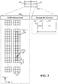
- FIG. 3 an expanded view of an exemplary DL subframe 302 is illustrated, showing an OFDM resource grid 304.
- the PHY transmission structure for any particular application may vary from the example described here, depending on any number of factors.
- time is in the horizontal direction with units of OFDM symbols; and frequency is in the vertical direction with units of subcarriers or tones.
- the resource grid 304 may be used to schematically represent time-frequency resources for a given antenna port. That is, in a MIMO implementation with multiple antenna ports available, a corresponding multiple number of resource grids 304 may be available for communication.
- the resource grid 304 is divided into multiple resource elements (REs) 306.
- An RE which is 1 subcarrier ⁇ 1 symbol, is the smallest discrete part of the time-frequency grid, and contains a single complex value representing data from a physical channel or signal.
- each RE may represent one or more bits of information.
- a block of REs may be referred to as a physical resource block (PRB) or more simply a resource block (RB) 308, which contains any suitable number of consecutive subcarriers in the frequency domain.
- PRB physical resource block
- RB resource block
- an RB may include 12 subcarriers, a number independent of the numerology used.
- an RB may include any suitable number of consecutive OFDM symbols in the time domain.
- a UE generally utilizes only a subset of the resource grid 304.
- An RB may be the smallest unit of resources that can be allocated to a UE.
- the RB 308 is shown as occupying less than the entire bandwidth of the subframe 302, with some subcarriers illustrated above and below the RB 308.
- the subframe 302 may have a bandwidth corresponding to any number of one or more RBs 408.
- the RB 308 is shown as occupying less than the entire duration of the subframe 302, although this is merely one possible example.
- Each 1 ms subframe 302 may consist of one or multiple adjacent slots.
- one subframe 302 includes four slots 310, as an illustrative example.
- a slot may be defined according to a specified number of OFDM symbols with a given cyclic prefix (CP) length.
- CP cyclic prefix
- a slot may include 7 or 14 OFDM symbols with a nominal CP.
- Additional examples may include mini-slots having a shorter duration (e.g., one or two OFDM symbols). These mini-slots may in some cases be transmitted occupying resources scheduled for ongoing slot transmissions for the same or for different UEs.
- An expanded view of one of the slots 310 illustrates the slot 310 including a control region 312 and a data region 314.
- the control region 312 may carry control channels (e.g., PDCCH)
- the data region 314 may carry data channels (e.g., PDSCH or PUSCH).
- a slot may contain all DL, all UL, or at least one DL portion and at least one UL portion.
- the simple structure illustrated in FIG. 3 is merely exemplary in nature, and different slot structures may be utilized, and may include one or more of each of the control region(s) and data region(s).
- the various REs 306 within a RB 308 may be scheduled to carry one or more physical channels, including control channels, shared channels, data channels, etc.
- Other REs 306 within the RB 308 may also carry pilots or reference signals, including but not limited to a demodulation reference signal (DMRS) a control reference signal (CRS), or a sounding reference signal (SRS).
- DMRS demodulation reference signal
- CRS control reference signal
- SRS sounding reference signal
- pilots or reference signals may provide for a receiving device to perform channel estimation of the corresponding channel, which may enable coherent demodulation/detection of the control and/or data channels within the RB 308.
- the transmitting device may allocate one or more REs 306 (e.g., within a control region 312) to carry DL control information 114 including one or more DL control channels, such as a PBCH; a PSS; a SSS; a physical control format indicator channel (PCFICH); a physical hybrid automatic repeat request (HARQ) indicator channel (PHICH); and/or a physical downlink control channel (PDCCH), etc., to one or more scheduled entities 106.
- the PCFICH provides information to assist a receiving device in receiving and decoding the PDCCH.
- the PDCCH carries downlink control information (DCI) including but not limited to power control commands, scheduling information, a grant, and/or an assignment of REs for DL and UL transmissions.
- DCI downlink control information
- the PHICH carries HARQ feedback transmissions such as an acknowledgment (ACK) or negative acknowledgment (NACK).
- HARQ is a technique well-known to those of ordinary skill in the art, wherein the integrity of packet transmissions may be checked at the receiving side for accuracy, e.g., utilizing any suitable integrity checking mechanism, such as a checksum or a cyclic redundancy check (CRC). If the integrity of the transmission confirmed, an ACK may be transmitted, whereas if not confirmed, a NACK may be transmitted. In response to a NACK, the transmitting device may send a HARQ retransmission, which may implement chase combining, incremental redundancy, etc.
- CRC cyclic redundancy check
- the transmitting device may utilize one or more REs 306 to carry UL control information 118 including one or more UL control channels, such as a physical uplink control channel (PUCCH), to the scheduling entity 108.
- UL control information may include a variety of packet types and categories, including pilots, reference signals, and information configured to enable or assist in decoding uplink data transmissions.
- the control information 118 may include a scheduling request (SR), e.g., a request for the scheduling entity 108 to schedule uplink transmissions.
- SR scheduling request
- the scheduling entity 108 may transmit downlink control information 114 that may schedule resources for uplink packet transmissions.
- UL control information may also include HARQ feedback, channel state feedback (CSF), or any other suitable UL control information.
- one or more REs 306 may be allocated for user data or traffic data. Such traffic may be carried on one or more traffic channels, such as, for a DL transmission, a physical downlink shared channel (PDSCH); or for an UL transmission, a physical uplink shared channel (PUSCH).
- PDSCH physical downlink shared channel
- PUSCH physical uplink shared channel
- one or more REs 306 within the data region 314 may be configured to carry system information blocks (SIBs), carrying information that may enable access to a given cell.
- SIBs system information blocks
- channels or carriers described above and illustrated in FIGs. 1 and 3 are not necessarily all the channels or carriers that may be utilized between a scheduling entity 108 and scheduled entities 106, and those of ordinary skill in the art will recognize that other channels or carriers may be utilized in addition to those illustrated, such as other traffic, control, and feedback channels.
- Transport channels carry blocks of information called transport blocks (TB).
- TBS transport block size
- MCS modulation and coding scheme
- one or more slots may be structured as self-contained slots.
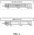
- FIG. 4 illustrates two example structures of self-contained slots 400 and 450.
- the self-contained slots 400 and/or 450 may be used, in some examples, in place of the slot 310 described above and illustrated in FIG. 3 .
- a DL-centric slot 400 may be a transmitter-scheduled slot.
- the nomenclature DL-centric generally refers to a structure wherein more resources are allocated for transmissions in the DL direction (e.g., transmissions from the scheduling entity 108 to the scheduled entity 106).
- an UL-centric slot 450 may be a receiver-scheduled slot, wherein more resources are allocated for transmissions in the UL direction (e.g., transmissions from the scheduled entity 106 to the scheduling entity 108).
- Each slot such as the self-contained slots 400 and 450, may include transmit (Tx) and receive (Rx) portions.
- the scheduling entity 108 first has an opportunity to transmit control information, e.g., on a PDCCH, in a DL control region 402, and then an opportunity to transmit DL user data or traffic, e.g., on a PDSCH in a DL data region 404.
- the scheduling entity 108 has an opportunity to receive UL data and/or UL feedback including any UL scheduling requests, CSF, a HARQ ACK/NACK, etc., in an UL burst 408 from other entities using the carrier.
- GP guard period
- a slot such as the DL-centric slot 400 may be referred to as a self-contained slot when all of the data carried in the data region 404 is scheduled in the control region 402 of the same slot; and further, when all of the data carried in the data region 404 is acknowledged (or at least has an opportunity to be acknowledged) in the UL burst 408 of the same slot.
- each self-contained slot may be considered a self-contained entity, not necessarily requiring any other slot to complete a scheduling-transmission-acknowledgment cycle for any given packet.
- the GP region 406 may be included to accommodate variability in UL and DL timing. For example, latencies due to radio frequency (RF) antenna direction switching (e.g., from DL to UL) and transmission path latencies may cause the scheduled entity 106 to transmit early on the UL to match DL timing. Such early transmission may interfere with symbols received from the scheduling entity 108. Accordingly, the GP region 406 may allow an amount of time after the DL data region 404 to prevent interference, where the GP region 406 provides an appropriate amount of time for the scheduling entity 108 to switch its RF antenna direction, an appropriate amount of time for the over-the-air (OTA) transmission, and an appropriate amount of time for ACK processing by the scheduled entity.
- OTA over-the-air
- the UL-centric slot 450 may be configured as a self-contained slot.
- the UL-centric slot 450 is substantially similar to the DL-centric slot 400, including a DL control region 450, a guard period 454, an UL data region 456, and an UL burst region 458.
- slots 400 and 450 is merely one example of self-contained slots. Other examples may include a common DL portion at the beginning of every slot, and a common UL portion at the end of every slot, with various differences in the structure of the slot between these respective portions. Other examples still may be provided within the scope of the present disclosure.
- the UL burst 408 of the DL-centric slot 400, and the UL data region 456 and UL burst region 458 of the UL-centric slot 450 can each include one or more DMRS sequences.
- a DMRS sequence may occupy one or more resource elements 306 in each UL region, typically being in the first one or two symbols.
- a first UE 226 chooses a DMRS sequence from a set of N known DMRS sequences. In this way, log 2 (N) bits of uplink control information (UCI) can be communicated using specific DMRS sequences.
- the UCI may include one or more of a HARQ ACK/NACK, a scheduling request, channel state information (CSI), channel quality information (CQI), precoding matrix indicator (PMI), rank indicator (RI), procedure transaction identifier (PTI), discontinued transmission/reception (DTX/DRX), etc.
- CSI channel state information
- CQI channel quality information
- PMI precoding matrix indicator
- RI rank indicator
- PTI procedure transaction identifier
- DTX/DRX discontinued transmission/reception
- the first UE 226 then communicates a UL transmission to a base station 212, where the UL transmission includes the UCI payload within the DMRS.
- the set of N possible DMRS sequences are known between at least the first UE and the base station 212.
- DMRS information containing the N possible DMRS sequences may be stored in a memory on each of the base station 212 and the first UE 226.
- the set of N possible DMRS sequences may also be known to a second UE 228, thereby allowing direct D2D communication between the second UE 228 and both of the first UE 226 and the base station 212.
- the DMRS sequence may be chosen based on the UCI information to be communicated using a look-up table that is stored within the DMRS information.
- the look-up table may include particular UCI information and/or particular combinations of UCI information that correspond to each of the N known DMRS sequences.
- a particular DMRS sequence communicated from the first UE 226 to the base station 212 may correspond to a HARQ ACK message.
- the look-up table may include a one-to-one correspondence between the DMRS sequence and the at least one UCI payload. Table 1 below illustrates an example of such a look-up table.
- UCI payload (X) DMRS Sequence ACK 1 NACK 2 DTX/DRX 3
- the first UE 226 communicates a HARQ ACK message to the base station 212 via DMRS sequence 1.
- the first UE 226 chooses at least one DMRS sequence for a UL transmission, and configures the UL data region 456 and/or the UL burst region 458 to include the chosen sequence(s). For example, the first UE 226 may communicate a HARQ ACK message to the base station 212 by selecting DMRS sequence 1 for transmission in the UL data region 456. The same process can be used in the UL burst region 408 of the DL-centric slot 400. Note that any suitable number of DMRS sequences N may be utilized to correspond to any UCI payload X .
- the base station 212 may confirm a relationship between the DMRS sequence and the UCI payload by determining which DMRS sequence was communicated in the UL transmission, and determining which UCI(s) correspond to the DMRS sequence.
- the base station 212 may establish a magnitude of correlation against the N possible DMRS sequences in the stored DMRS information to determine which DMRS sequence was communicated in the UL transmission.
- DMRS sequences can be chosen by the first UE to be orthogonal to one another or have low cross correlation between one another.
- DMRS sequences may have an embedded pilot sub-sequence that is common among all or a portion of the N possible choices of DMRS sequences.
- the embedded pilot sub-sequences may be utilized for channel estimation to aid in detecting which DMRS sequence was transmitted.
- a common pilot sub-sequence e.g., a first pilot sub-sequence
- DMRS sequence 1 corresponding to a first ACK
- DMRS sequence 2 corresponding to a first NACK
- DMRS sequence 3 corresponding to a first DTX
- a second pilot sub-sequence may be embedded in a DMRS sequence 4 (corresponding to a second ACK), a DMRS sequence 5 (corresponding to a second NACK), and a DMRS sequence 6 (corresponding to a second DTX).
- the first pilot sub-sequence is distinguishable from the second pilot sub-sequence.
- Such distinguishing features may be utilized by the base station 212 to establish a UE specific parameter (e.g., UE identity) associated with the UL transmission.
- each of the N possible choices of DMRS sequences or the portion of the N DMRS sequences may include a unique embedded pilot sub-sequence.
- a single DMRS sequence may correspond to a plurality of UCIs.
- the single DMRS sequence may include an embedded pilot sub-sequences that corresponds to a unique one of the plurality of UCIs.
- a common DMRS sequence may be used to communicate a plurality of UCIs, wherein the embedded pilot sub-sequence distinguishes the common DMRS sequence to a unique one of the plurality of UCIs.
- a scheduling entity 108 may be configured to drop certain data in order to reduce latency.
- the base station 212 and/or the scheduled entity 106 may be configured to ignore a UCI carried in this manner if the number of HARQ transmissions exceed a threshold.
- the threshold could be 1 (i.e., the UCI is only considered valid if it is decoded at the first transmission).
- a maximum number of HARQ transmissions allowed may be dynamically generated by the base station 212 and signaled to the first UE 226 in a DCI containing a PUSCH grant.
- the threshold may be set to a relatively lower value for PUSCH grants associated with a payload including both UCI and PUSCH data, than for a PUSCH grant associated with a payload that does not include UCI data.
- the first UE 226 may segment a payload of an UL transmission into multiple, independently acknowledged code block groups (CBGs).
- the base station 212 may generate threshold values corresponding to the maximum number of HARQ retransmissions, where a first threshold value corresponding to CBGs containing UCI data may be different than a second threshold value corresponding to CBGs that do not.
- the value of N may be limited to reduce complexity.
- the value of N may be chosen to carry non-binary UCI types.
- One example of a three-state UCI may include a three-state ACK that can provide information that is in addition to the standard ACK/NACK.
- the three-state ACK can reflect complex states, such as, (i) no PDCCH detected, (ii) PDCCH detected but PDSCH CRC failed, and (iii) PDCCH detected and PDSCH CRC passed.
- a scheduled entity 106 may provide an ACK (i.e., PDCCH detected and PDSCH CRC passed), a NACK (i.e., PDCCH detected but PDSCH CRC failed), or a discontinued transmission/reception (DTX/DRX) message over the DMRS.
- ACK i.e., PDCCH detected and PDSCH CRC passed
- NACK i.e., PDCCH detected but PDSCH CRC failed
- DTX/DRX discontinued transmission/reception
- the scheduled entity 106 can assign a first power level to a UCI carried by a DMRS sequence of a slot, and a second power level to another UCI being communicated in the payload of the same slot.
- the first UE 226 may communicate an UL transmission containing a first UCI (e.g., a 2-bit ACK) via a DMRS sequence, as well as a second UCI (e.g., a 1-bit ACK) via a PUCCH.
- the first UE 226 may be communicating a three-state ACK to the base station 212.
- first UCI and the second UCI can be assigned different reliability requirements due to demodulation requirements being different for each.
- first UE 226 can modulate a transmission power level of each of the first UCI and the second UCI to indicate or impose upon the base station 212 distinctive decoding reliability requirements for each UCI.
- the first UE 226 may increase the transmission power level on information deemed important (e.g., the first UCI of the DMRS), and decrease (i.e., reduce relative to the increase power level, or leave at a nominal or default level) the power for information that is relatively less important (e.g., the second UCI of the PUCCH).
- Selectively modulating power allows the first UE 226 to generate a delta offset between different UCIs of the same slot to indicate degrees of reliability, and also to employ power saving measures.
- latency requirements of different UCIs can be controlled by strategically configuring a particular arrangement of the UCIs within a slot.
- Such a configuration is beneficial for enabling a scheduled entity 106 and/or a scheduling entity 108 to establish a timeline prioritization of information.
- the DMRS sequence is generally "up front" or at the beginning of any of the UL burst and/or UL data region of a slot. As such, this property of the DMRS sequence can be utilized to front-load a particular UCI (e.g., a first UCI) in the UL region of a transmission.
- the first UE 226 can determine that the first UCI should receive timeline prioritization over a second UCI.
- the first UCI may be carried on the DMRS and the second UCI may be carried via the PUCCH.
- the arrangement of the UCIs within the slot results in the first UCI being processed earlier than the second UCI.
- the first UE 226 may establish a timeline of prioritization by selecting one or more DMRS sequences based on a priority of one or more UCIs.
- the priority of a UCI may be a function of a priority of data that the UCI is in response to. For example, if the UCI is a 1-bit ACK associated with mission critical data received by the first UE 226, then the first UE 226 may choose a DMRS sequence associated with a 1-bit ACK instead of transmitting the 1-bit ACK by the PUCCH. In this example, the priority of the 1-bit ACK was established by the priority of the mission critical data received by the first UE 226.
- mission critical data refers to data that has a relatively high reliability requirement. For example, the reliability requirement of mission critical data may be greater than the reliability requirement of other data included in that subframe. Generally, reliability refers to how consistently data is successfully received by the intended destination without errors.
- the priority of the UCI may be a function of the type of UCI.
- the priority may be determined by characteristics of the UCI, including number of bits, whether the UCI includes a CSI, an ACK, a NACK, and/or an SR.
- a 1-bit UCI may have a relatively higher priority established by the number of bits of the UCI, whereas a 2-bit ACK may have a relatively lower priority due to having a greater number of bits.
- whether the scheduled entity 226 chooses a particular DMRS sequence for a UCI may be a function of one or more of (i) the priority of the data that the UCI is in response to, (ii) the type of UCI, and (iii) the bit size of the UCI.
- an SR may be bundled with a larger payload.
- the larger payload may include one or more types of UCIs (e.g, CSI, CQI, HARQ ACK/NACK, etc.) and a data portion for PUCCH/PUSCH transmission.
- the SR may include one or more bits indicating whether the scheduled entity 106 is requesting resources for UL data transmissions, the SR may increase in bit-size when additional bits are added to convey information about the amount and/or type of resources the scheduled entity 106 needs.
- the SR can also include a buffer status report (BSR).
- BSR buffer status report
- data bits may be stored in a buffer prior to being communicated in an UL transmission.
- the BSR can include the number of bits stored in that buffer, providing the scheduling entity 108 with information regarding an amount of resources the scheduled entity 106 needs.
- the BSR may include explicit data indicating the length of the buffer.
- the BSR may provide data that of reduced granularity than that of the explicit length to reduce latency. In such a case, with no more than two bits, the BSR can indicate a general capacity of the buffer.
- the BSR may include a first data including explicit information indicating the length of the buffer.
- the BSR may instead include a second data including information of a reduced granularity relative to that of the first data to reduce latency.
- the BSR may be reduced in bit size to indicate a general capacity of the buffer. In such a case, the BSR may be reduced to no more than two bits.
- a determination to communicate the BSR having the first data or the second data may be based on various priority metrics associated with one or more of the UCI or the PUCCH/PUSCH payload.
- priority refers to the importance or time-sensitivity of the data.
- a first data having relatively higher importance may not be modified, or reduced in size.
- a first data having relatively greater time-sensitivity may be modified so that the data may be received before other data having relatively lesser importance and/or relatively lesser time-sensitivity.
- the scheduled entity 106 may choose to bundle a UCI such as an SR with another UCI payload if the other UCI payload meets a threshold size requirement.
- the threshold size requirement may be determined based on single-payload information stored in a memory.
- the single-payload information may be communicated between the scheduled entity 106 and the scheduling entity 108.
- the single-payload information may include a relationship between a number of bits (M) of a UCI (e.g., SR), and a number of bits in the other UCI payload (X). Such a relationship may be based on a stored table of a set of allowed M vales and corresponding X values.
- the look-up table may contain a one-to-one correspondence between the threshold number of bits in the other UCI payload and the number of bits in the UCI.
- Table 2 below illustrates an example of such a table. Threshold number of bits in the other UCI payload (X) Number of bits of the UCI (M) ⁇ 11 0 11 1 55 2 275 3
- the SR can be added to the payload so long as the SR contains 2 or fewer bits.
- the threshold may be dynamic and set based on reserved resources by either of the scheduling entity 108, or the scheduled entity 106.
- a UCI may be bundled into a single payload opportunistically based on resources available to either, or both of, the scheduled entity 106 and the scheduling entity 108.
- the scheduled entity 106 may operate by reserving resources for sending requested information, and limiting bundling of information to instances when the information is requested.
- an RRC, MAC-CE (MAC Control Element), DCI, or other control command exchange can trigger the scheduled entity to report a UCI (e.g., CQI, PMI, RI, PTI, etc.), which can be bundled so long as the reported UCI meets the threshold size.
- the RRC, MAC-CE, DCI, or other control command exchange may specify the threshold size.
- One or both of the scheduled entity 106 and the scheduling entity 108 may determine whether to transmit UCI information by embedding it in the DMRS, or bundling it with another payload. Such a determination may be based on a number of parameters. Such parameters include, a bit size of a UCI, how reliable the UCI is required to be, the processing requirements of either, or both of, the scheduled entity 106 and the scheduling entity 108, power requirements, amount of available resources of either, or both of, the scheduled entity 106 and the scheduling entity 108.
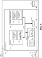
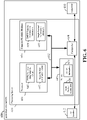
- FIG. 5 is a block diagram illustrating an example of a hardware implementation for a scheduling entity 500 employing a processing system 514.
- the scheduling entity 500 may be a user equipment (UE) as illustrated in any one or more of FIGs. 1 and/or 2.
- UE user equipment
- the scheduling entity 500 may be a base station as illustrated in any one or more of FIGs. 1 and/or 2.
- the scheduling entity 500 may be implemented with a processing system 514 that includes one or more processors 504.
- processors 504 include microprocessors, microcontrollers, digital signal processors (DSPs), field programmable gate arrays (FPGAs), programmable logic devices (PLDs), state machines, gated logic, discrete hardware circuits, and other suitable hardware configured to perform the various functionality described throughout this disclosure.
- the scheduling entity 500 may be configured to perform any one or more of the functions described herein. That is, the processor 504, as utilized in a scheduling entity 500, may be used to implement any one or more of the processes and procedures described below and illustrated in FIGs. 7-9 .
- the processing system 514 may be implemented with a bus architecture, represented generally by the bus 502.
- the bus 502 may include any number of interconnecting buses and bridges depending on the specific application of the processing system 514 and the overall design constraints.
- the bus 502 communicatively couples together various circuits including one or more processors (represented generally by the processor 504), a memory 505, and computer-readable media (represented generally by the computer-readable medium 506).
- the bus 502 may also link various other circuits such as timing sources, peripherals, voltage regulators, and power management circuits, which are well known in the art, and therefore, will not be described any further.
- a bus interface 508 provides an interface between the bus 502 and a transceiver 510.
- the transceiver 510 provides a communication interface or means for communicating with various other apparatus over a transmission medium.
- a user interface 512 e.g., keypad, display, speaker, microphone, joystick
- the processor 504 may include circuitry for determining a DMRS sequence 540 received in an UL communication.
- the scheduling entity 500 may receive, by the transceiver 510, an UL message including a DMRS sequence and at least one UCI.
- the at least one UCI may include any of a CSI, CQI, HARQ ACK/NACK, etc.
- the circuitry for determining a DMRS sequence 540 may determine whether the received DMRS sequence is configured to communicate a UCI by comparing the DMRS sequence with DMRS information 554 stored in the memory 505.
- the DMRS information 554 may include a look-up table including a plurality of DMRS sequences and their corresponding UCIs.
- the circuitry for determining a DMRS sequence 540 may determine which UCI is being communicated by the received DMRS sequence.
- the circuitry for determining a DMRS sequence 540 may also determine whether the received DMRS sequence includes an embedded pilot sub-sequence that corresponds to a UCI. For example, if the circuitry for determining a DMRS sequence 540 determines that the DMRS sequence contains an embedded pilot sub-sequence, the circuitry may compare the embedded pilot sub-sequence with another look-up table contained in the DMRS information 554 stored in the memory 505.
- the DMRS information 554 may include the other look-up table containing a plurality of pilot sub-sequences and their corresponding UCIs.
- the circuitry for determining a DMRS sequence 540 may determine which UCI was communicated by the embedded pilot sub-sequence contained within the DMRS sequence.
- the circuitry for determining a DMRS sequence 540 may also generate and communicate non-binary UCI types to the scheduled entity.
- the circuitry for determining a DMRS sequence 540 may store the non-binary UCI types in the DMRS information 554 in the memory 505, and communicate the non-binary UCI types to the scheduled entity via the transceiver 510.
- the three-state ACK is being used as an example, however other non-binary UCI types and corresponding N values are contemplated.
- the circuitry for determining a DMRS sequence 540 may assign a first power level to a UCI carried by a DMRS sequence of a slot, and a second power level to another UCI being communicated in the payload of the same slot.
- the power levels and corresponding UCIs may be stored in the DMRS information 554 and communicated to the scheduled entity.
- the circuitry for determining a DMRS sequence 540 may assign different reliability requirements to the first UCI and the second UCI due to demodulation requirements being different for each.
- the circuitry for determining a DMRS sequence 540 may determine latency requirements for different UCIs and strategic configurations of the UCIs within a slot. The arrangement of the UCIs within the slot results in one UCI being processed earlier than another UCI in the same slot.
- the scheduling entity 500 may store the latency requirements and strategic configurations in the DMRS information 554 in the memory 605.
- the priority of the UCI may be a function of the type of UCI.
- the priority may be determined by characteristics of the UCI, including number of bits, whether the UCI includes a CSI, an ACK, a NACK, and/or an SR.
- a 1-bit UCI may have a relatively higher priority established by the number of bits of the UCI, whereas a 2-bit ACK may have a relatively lower priority due to having a greater number of bits.
- the circuitry for determining a DMRS sequence 540 may generate and select a particular DMRS sequence for a UCI, wherein the selection may be based on a function of one or more of (i) the priority of the data that the UCI is in response to, (ii) the type of UCI, and (iii) the bit size of the UCI.
- the particular function may be stored in the DMRS information 554 in the memory 505.
- the circuitry for determining a DMRS sequence 540 may generate the DMRS information 554 and communicate it to a scheduled entity so that both the scheduling entity 500 and the scheduled entity have the same DMRS information 554.
- the circuitry for determining a DMRS sequence 540 may operate in coordination with the DMRS sequence determination software 550.
- the processor 504 may include circuitry for determining a single payload combination 542.
- the single payload combination circuit 542 may generate instructions and/or parameters for the scheduled entity to use in combining a UCI into a single payload in an UL communication.
- an RRC, MAC-CE (MAC Control Element), DCI, or other control command exchange generated by the processor 504 may include single payload information 556 generated by the single payload combination circuit.
- the scheduling entity may communicate the control command exchanged with the scheduled entity by the transceiver 510, and store the single payload information 556 in the memory 505.
- the single payload information 556 may be configured to trigger the scheduled entity to report a UCI (e.g., CQI, PMI, RI, PTI, etc.) bundled with an UL payload so long as the reported UCI meets a threshold size.
- a UCI e.g., CQI, PMI, RI, PTI, etc.
- the RRC, MAC-CE, DCI, or other control command exchange may specify the threshold size.
- the circuitry for single payload combination 542 may operate in coordination with the single payload combination software 552.
- the processor 504 is responsible for managing the bus 502 and general processing, including the execution of software stored on the computer-readable medium 506.
- the software when executed by the processor 504, causes the processing system 514 to perform the various functions described below for any particular apparatus.
- the computer-readable medium 506 and the memory 505 may also be used for storing data that is manipulated by the processor 504 when executing software.
- One or more processors 504 in the processing system may execute software.
- Software shall be construed broadly to mean instructions, instruction sets, code, code segments, program code, programs, subprograms, software modules, applications, software applications, software packages, routines, subroutines, objects, executables, threads of execution, procedures, functions, etc., whether referred to as software, firmware, middleware, microcode, hardware description language, or otherwise.
- the software may reside on a computer-readable medium 506.
- the computer-readable medium 506 may be a non-transitory computer-readable medium.
- a non-transitory computer-readable medium includes, by way of example, a magnetic storage device (e.g., hard disk, floppy disk, magnetic strip), an optical disk (e.g., a compact disc (CD) or a digital versatile disc (DVD)), a smart card, a flash memory device (e.g., a card, a stick, or a key drive), a random access memory (RAM), a read only memory (ROM), a programmable ROM (PROM), an erasable PROM (EPROM), an electrically erasable PROM (EEPROM), a register, a removable disk, and any other suitable medium for storing software and/or instructions that may be accessed and read by a computer.
- a magnetic storage device e.g., hard disk, floppy disk, magnetic strip
- an optical disk e.g., a compact disc (CD) or a digital versatile disc (DVD)
- a smart card e.g., a flash memory device (e.g.
- the computer-readable medium 506 may reside in the processing system 514, external to the processing system 514, or distributed across multiple entities including the processing system 514.
- the computer-readable medium 506 may be embodied in a computer program product.
- a computer program product may include a computer-readable medium in packaging materials.
- the computer-readable storage medium 506 may include DMRS sequence determination software 550 configured for various functions, including, for example, selecting a first DMRS sequence from a plurality of DMRS sequences to be used in an UL message, wherein one or more of the DMRS sequences are configured to communicated a UCI, and transmit the UL message.
- the DMRS sequence determination software 550 may also be configured to receive an UL message including a DMRS sequence and at least one UCI, and determining the at least one UCI based on the DMRS sequence in the UL message.
- the DMRS sequence determination software 550 may be configured to implement one or more of the functions described above in relation to FIGs. 7 and 9 , including, e.g., blocks 702 and 704.
- the computer-readable storage medium 506 may include single payload combination software 552 configured for various functions, including, for example, determining a bit size of a UCI, comparing the bit size of the UCI with a threshold value based on the size of a payload, determining whether the UCI bit size is greater than the threshold value, determining whether UCI can be embedded in the DMRS, and combining the UCI with the payload.
- the single payload combination software 552 may be configured to implement one or more of the functions described above in relation to FIG. 8 , including, e.g., blocks 802-810.
- FIG. 6 is a conceptual diagram illustrating an example of a hardware implementation for a scheduled entity 600 employing a processing system 614.
- the scheduled entity 600 may be a user equipment (UE) as illustrated in any one or more of FIGs. 1 and/or 2.
- UE user equipment
- the scheduled entity 600 may be a base station as illustrated in any one or more of FIGs. 1 , 2 , and/or 5.
- the processing system 614 may be substantially the same as the processing system 514 illustrated in FIG. 5 , including a bus interface 608, a bus 602, memory 605, a processor 604, and a computer-readable medium 606.
- the scheduled entity 600 may include a user interface 612 and a transceiver 610 substantially similar to those described above in FIG. 5 . That is, the processor 604, as utilized in a scheduled entity 600, may be used to implement any one or more of the processes described below and illustrated in FIGs. 7-9 .
- the processor 604 may include circuitry for determining a DMRS sequence 640 based at least on a latency requirement, power requirements, and/or a UCI type.
- the circuitry for determining a DMRS sequence 640 may select at least one DMRS sequence for a UL transmission, and configures the UL data region 456 and/or the UL burst region 458 to include the chosen sequence(s).
- the circuitry for determining a DMRS sequence 640 may communicate a HARQ ACK message to the scheduling entity 500 by selecting a corresponding DMRS sequence for transmission by the transceiver 610. Any suitable number of DMRS sequences (N) may be utilized to correspond to any UCI payload.
- the N number of DMRS sequences may be stored as DMRS information in the memory 605.
- the circuitry for determining a DMRS sequence 640 may generate the DMRS information, or the scheduling entity 500 may generate the DMRS information 654 and communicate the DMRS information 654 to the scheduled entity 600.
- the scheduled entity 600 may receive the DMRS information 654 via the transceiver 610 and store the DMRS information 654 in the memory.
- DMRS sequences can be chosen by the circuitry for determining a DMRS sequence 640 to be orthogonal to one another or have low cross correlation between one another.
- the circuitry for determining a DMRS sequence 640 may also select an embedded pilot sub-sequence from a plurality of pilot sub-sequences stored in the DMRS information 654 in the memory 605.
- a common pilot sub-sequence e.g., a first pilot sub-sequence
- the circuitry for determining a DMRS sequence 640 may also generate and/or receive non-binary UCI types.
- the circuitry for determining a DMRS sequence 640 may store the non-binary UCI types in the DMRS information 554 in the memory 505, and communicate the non-binary UCI types to the scheduled entity via the transceiver 510.
- the three-state ACK is being used as an example, however other non-binary UCI types and corresponding N values are contemplated.
- the circuitry for determining a DMRS sequence 640 may assign a first power level to a UCI carried by a DMRS sequence of a slot, and a second power level to another UCI being communicated in the payload of the same slot.
- the power levels and corresponding UCIs may be stored in the DMRS information 654 and communicated to the scheduled entity.
- the scheduled entity 600 may communicate an UL transmission using the transceiver 610 and containing a first UCI (e.g., a 2-bit ACK) embedded in a DMRS sequence, as well as a second UCI (e.g., a 1-bit ACK) via a PUCCH.
- a first UCI e.g., a 2-bit ACK
- a second UCI e.g., a 1-bit ACK
- the scheduled entity 600 may be communicating a three-state ACK to the scheduling entity.
- the circuitry for determining a DMRS sequence 640 may assign the first UCI and the second UCI different reliability requirements due to demodulation requirements being different for each.
- the DMRS sequence determination circuit 640 may modulate a transmission power level of each of the first UCI and the second UCI to indicate distinctive decoding reliability requirements for each UCI.
- the circuitry for determining a DMRS sequence 640 may determine latency requirements for different UCIs and strategically configure a particular arrangement of the UCIs within a slot. The arrangement of the UCIs within the slot results in one UCI being processed earlier than another UCI in the same slot.
- the scheduled entity 600 may receive the latency requirements and particular arrangements and store the information in the DMRS information 654.
- the priority of the UCI may be a function of the type of UCI.
- the priority may be determined by characteristics of the UCI, including number of bits, whether the UCI includes a CSI, an ACK, a NACK, and/or an SR.
- a 1-bit UCI may have a relatively higher priority established by the number of bits of the UCI, whereas a 2-bit ACK may have a relatively lower priority due to having a greater number of bits.
- the DMRS sequence determination circuit 640 may generate and select a particular DMRS sequence for a UCI, wherein the selection may be based on a function of one or more of the (i) the priority of the data that the UCI is in response to, (ii) the type of UCI, and (iii) the bit size of the UCI.
- the particular function may be stored in the DMRS information 654 in the memory 605.
- the circuitry for determining a DMRS sequence 640 may generate the DMRS information 654 and communicate it to a scheduling entity so that both the scheduling entity and the scheduled entity 600 have the same DMRS information 654.
- the circuitry for determining a DMRS sequence 640 may operate in coordination with the DMRS sequence determination software 650.
- the processor 604 may include circuitry for determining a single payload combination 642.
- the circuitry for single payload combination 642 may bundle the bits of UCIs into a single PUCCH/PUSCH payload of UL communication if the payload meets a size requirement.
- the threshold size requirement may be determined based on single-payload information 656 stored in a memory.
- the circuitry for single payload combination 642 may bundle a UCI such as an SR with a larger payload.
- the larger payload may include one or more types of UCIs (e.g, CSI, CQI, HARQ ACK/NACK, etc.) and a data portion for PUCCH/PUSCH transmission.
- the SR may include one or more bits indicating whether the scheduled entity 600 is requesting resources for UL data transmissions
- the SR may increase in bit-size when additional bits are added to convey information about the amount and/or type of resources the scheduled entity 600 needs.
- the SR can also include a buffer status report (BSR).
- BSR buffer status report
- data bits may be stored in a buffer or memory 605 as single payload information 656 prior to being communicated in an UL transmission.
- the BSR can include the number of bits stored in buffer, providing the scheduling entity with information regarding an amount of resources the scheduled entity 600 needs.
- the BSR may include explicit data indicating the length of the buffer.
- the BSR may provide data that of reduced granularity than that of the explicit length to reduce latency. In such a case, with no more than two bits, the BSR can indicate a general capacity of the buffer.
- the BSR may include a first data including explicit information indicating the length of the buffer.
- the BSR may instead include a second data including information of a reduced granularity relative to that of the first data to reduce latency.
- the BSR instead of providing explicit information indicating the length of the buffer, the BSR may be reduced in bit size to indicate a general capacity of the buffer. In such a case, the BSR may be reduced to no more than two bits.
- the circuitry for single payload combination 642 may determine to communicate the BSR having the first data or the second data based on various priority metrics associated with one or more of the UCI or the PUCCH/PUSCH payload.
- the circuitry for single payload combination 642 may bundle a UCI into a single payload opportunistically based on resources available to either, or both of, the scheduled entity 600 and the scheduling entity.
- the scheduled entity 600 may operate by reserving resources for sending requested information, and limiting bundling of information to instances when the information is requested.
- an RRC, MAC-CE (MAC Control Element), DCI, or other control command exchange can trigger the scheduled entity to report a UCI (e.g., CQI, PMI, RI, PTI, etc.), which can be bundled so long as the reported UCI meets the threshold size.
- the RRC, MAC-CE, DCI, or other control command exchange may specify the threshold size.
- the computer-readable storage medium 606 may include DMRS sequence determination software 650 configured for various functions, including, for example, selecting a first DMRS sequence from a plurality of DMRS sequences to be used in an UL message, wherein one or more of the DMRS sequences are configured to communicated a UCI, and transmit the UL message.
- the DMRS sequence determination software 650 may also be configured to receive an UL message including a DMRS sequence and at least one UCI, and determining the at least one UCI based on the DMRS sequence in the UL message.
- the DMRS sequence determination software 650 may be configured to implement one or more of the functions described above in relation to FIGs. 7 and 9 , including, e.g., blocks 702 and 704.
- the computer-readable storage medium 606 may include single payload combination software 652 configured for various functions, including, for example, determining a bit size of a UCI, comparing the bit size of the UCI with a threshold value based on the size of a payload, determining whether the UCI bit size is greater than the threshold value, determining whether UCI can be embedded in the DMRS, and combining the UCI with the payload.
- the single payload combination software 652 may be configured to implement one or more of the functions described above in relation to FIG. 8 , including, e.g., blocks 802-810.
- FIG. 7 is a flow chart illustrating an exemplary process 700 for embedding uplink control information within a DMRS in a UL message.
- the process 700 may be carried out by the scheduling entity 500 and/or the scheduled entity 600 illustrated in FIGs. 5 and 6 , respectively.
- the process 700 may be carried out by any suitable apparatus or means for carrying out the functions or algorithm described below
- a scheduled entity 600 chooses a DMRS sequence from N known sequences that are stored on a memory 605 as DMRS information 654.
- the UL burst 408 of the DL-centric slot 400, and the UL data region 456 and UL burst region 458 of the UL-centric slot 450 can each include one or more DMRS sequences.
- a DMRS sequence may occupy one or more resource elements 306 in each UL region. In this way, log 2 (N) bits of uplink control information (UCI) can be communicated using specific DMRS sequences.
- UCI uplink control information
- the UCI may include one or more of a HARQ ACK/NACK, an SR, a CSI, a CQI, a PMI, an RI, a PTI, a DTX/DRX, etc.
- the DMRS sequence may be chosen based on the UCI information to be communicated using a look-up table that is stored within the DMRS information 654 on a memory 605.
- the look-up table may include particular UCI information and/or particular combinations of UCI information that correspond to each of the N known DMRS sequences.
- the scheduled entity 600 may select at least one DMRS sequence for a UL transmission, and configure the UL data region 456 and/or the UL burst region 458 to include the selected sequence(s). For example, the scheduled entity 600 may communicate a HARQ ACK message by selecting a corresponding DMRS sequence for transmission in the UL data region 456. The same process can be used in the UL burst region 408 of the DL-centric slot 400. Note that any suitable number of DMRS sequences N may be utilized to correspond to any UCI payload X. DMRS sequences can be chosen by the first UE to be orthogonal to one another or have low cross correlation between one another.
- DMRS sequences may have an embedded pilot sub-sequence that is common among all or a portion of the N possible choices of DMRS sequences.
- the embedded pilot sub-sequences may be utilized for channel estimation to aid in detecting which DMRS sequence was transmitted.
- a common pilot sub-sequence e.g., a first pilot sub-sequence
- DMRS sequence 1 corresponding to a first ACK
- DMRS sequence 2 corresponding to a first NACK
- DMRS sequence 3 corresponding to a first DTX
- a second pilot sub-sequence may be embedded in a DMRS sequence 4 (corresponding to a second ACK), a DMRS sequence 5 (corresponding to a second NACK), and a DMRS sequence 6 (corresponding to a second DTX).
- the first pilot sub-sequence is distinguishable from the second pilot sub-sequence.
- each of the N possible choices of DMRS sequences or the portion of the N DMRS sequences may include a unique embedded pilot sub-sequence.
- a single DMRS sequence may correspond to a plurality of UCIs.
- the single DMRS sequence may include an embedded pilot sub-sequences that corresponds to a unique one of the plurality of UCIs.
- a common DMRS sequence may be used to communicate a plurality of UCIs, wherein the embedded pilot sub-sequence distinguishes the common DMRS sequence to a unique one of the plurality of UCIs.
- the value of N may be limited to reduce complexity.
- the value of N may be chosen to carry non-binary UCI types.
- One example of a three-state UCI may include a three-state ACK that can provide information that is in addition to the standard ACK/NACK.
- the three-state ACK can reflect complex states, such as, (i) no PDCCH detected, (ii) PDCCH detected but PDSCH CRC failed, and (iii) PDCCH detected and PDSCH CRC passed.
- a scheduled entity 106 may provide an ACK (i.e., PDCCH detected and PDSCH CRC passed), a NACK (i.e., PDCCH detected but PDSCH CRC failed), or a discontinued transmission/reception (DTX/DRX) message over the DMRS.
- ACK i.e., PDCCH detected and PDSCH CRC passed
- NACK i.e., PDCCH detected but PDSCH CRC failed
- DTX/DRX discontinued transmission/reception
- the scheduled entity 600 can assign a first power level to a UCI carried by a DMRS sequence of a slot, and a second power level to another UCI being communicated in the payload of the same slot.
- the scheduled entity 600 may generate an UL message containing a first UCI (e.g., a 2-bit ACK) via a DMRS sequence, as well as a second UCI (e.g., a 1-bit ACK) via a PUCCH.
- the generated UL message may be a three-state ACK.
- the first UCI and the second UCI can be assigned different reliability requirements due to demodulation requirements being different for each.
- scheduled entity 600 can modulate a transmission power level of each of the first UCI and the second UCI to indicate distinctive decoding reliability requirements for each UCI.
- the scheduled entity 600 may increase the transmission power level on information deemed important (e.g., the first UCI of the DMRS), and decrease (i.e., reduce relative to the increase power level, or leave at a nominal or default level) the power for information that is relatively less important (e.g., the second UCI of the PUCCH).
- Selectively modulating power allows the scheduled entity 600 to generate a delta offset between different UCIs of the same slot to indicate degrees of reliability, and also to employ power saving measures.
- the scheduled entity may control latency requirements of different UCIs by strategically configuring a particular arrangement of the UCIs within a slot.
- Such a configuration is beneficial for establishing a timeline prioritization of information.
- the DMRS sequence is generally "up front" or at the beginning of any of the UL burst and/or UL data region of a slot.
- this property of the DMRS sequence can be utilized to front-load a particular UCI (e.g., a first UCI) in the UL region of a transmission.
- the scheduled entity 600 is generating a UL-centric slot 450 that includes at least two UCIs, the scheduled entity 600 can determine that the first UCI should receive timeline prioritization over a second UCI.
- the first UCI may be carried on the DMRS and the second UCI may be carried via the PUCCH.
- the arrangement of the UCIs within the slot results in the first UCI being processed earlier than the second UCI.
- the scheduled entity 600 may establish a timeline of prioritization by generating an UL message where one or more DMRS sequences are selected based on a priority of one or more UCIs.
- the priority of a UCI may be a function of a priority of data that the UCI is in response to. For example, if the UCI is a 1-bit ACK associated with mission critical data received by the scheduled entity 600, then the scheduled entity may generate an UL message by selecting a DMRS sequence associated with a 1-bit ACK instead of transmitting the 1-bit ACK by the PUCCH. In this example, the priority of the 1-bit ACK is established by the priority of the mission critical data received by the scheduled entity 600.
- mission critical data refers to data that has a relatively high reliability requirement. For example, the reliability requirement of mission critical data may be greater than the reliability requirement of other data included in that subframe. Generally, reliability refers to how consistently data is successfully received by the intended destination without errors.
- the priority of the UCI may be a function of the type of UCI.
- the priority may be determined by characteristics of the UCI, including number of bits, whether the UCI includes a CSI, an ACK, a NACK, and/or an SR.
- a 1-bit UCI may have a relatively higher priority established by the number of bits of the UCI, whereas a 2-bit ACK may have a relatively lower priority due to having a greater number of bits.
- whether the scheduled entity 600 selects a particular DMRS sequence for a UCI may be a function of one or more of the (i) the priority of the data that the UCI is in response to, (ii) the type of UCI, and (iii) the bit size of the UCI.
- the scheduled entity 600 transmits the UL message containing the first DMRS sequence.
- the scheduling entity 500 and/or the scheduled entity 600 for wireless communication includes means for selecting a first DMRS sequence from a plurality of DMRS sequences to be used in an UL message, wherein one or more of the DMRS sequences are configured to communicate a UCI, and transmitting the UL message.
- the aforementioned means may be the processors 504 and/or 604.
- the aforementioned means may be the transceivers 510 and/or 610, configured to perform the functions recited in the aforementioned means.
- the aforementioned means may be a circuit or any apparatus configured to perform the functions recited by the aforementioned means.
- FIG. 8 is a flow chart illustrating an exemplary process 800 for adding a UCI to a payload.
- the payload may include one or more types of other UCI information, and may also include data payload for PUSCH transmission.
- the process 800 may be carried out by the scheduling entity 500 and/or the scheduled entity 600 illustrated in FIGs. 5 and 6 , respectively.
- the process 800 may be carried out by any suitable apparatus or means for carrying out the functions or algorithm described below.
- the scheduled entity 600 determines a bit size of the UCI.
- the number of UCI bits may change.
- a scheduled entity receiving multiple-input and multiple-output (MIMO) transmissions can receive DL data over one, two, or many different data streams at different times.
- MIMO multiple-input and multiple-output
- the UCI corresponding to the ACK would vary accordingly, with a different ACK needed for each of the different data streams.
- the scheduling entity may request channel state feedback (CSF) for a single wideband channel estimate; while at another time, the scheduling entity may request CSF for many different narrowband channel estimates.
- CSF channel state feedback
- UCI bit-size may also vary based on latency reducing measures. For example, reduced latency of control information via DMRS sequencing may indirectly reduce other UCI and/or data aspects due to faster transport of control signaling.
- the scheduled entity 600 compares the bit size of the UCI with a threshold value that is determined based on the size of the payload, where payload may include one or more types of UCI and may also include data payload for PUSCH transmission.
- payload may include one or more types of UCI and may also include data payload for PUSCH transmission.
- the allowable bit size of the UCI is a function of the bit size of the payload.
- the scheduled entity 600 determines whether the bit size of the UCI is greater than the threshold value. If the UCI bit size is greater than the threshold value, then the process move on to block 808. If the UCI bit size is not greater than the threshold value, then the process moves on to block 810.
- the scheduled entity 600 determines whether the UCI can be embedded in a DMRS of the UL message. If the UCI can be embedded, then the process moves on to that shown in Figure 7 . If the UCI cannot be embedded in a DMRS, then the UCI is transmitted at the next available opportunity.
- the scheduled entity 600 combines the UCI with the payload.
- the scheduling entity 500 and/or the scheduled entity 600 for wireless communication includes means for determining a bit size of a UCI, comparing the bit size of the UCI with a threshold value based on the size of a payload, determining whether the UCI bit size is greater than the threshold value, determining whether the UCI can be embedded in the DMRS, and combining the UCI with the payload.
- the aforementioned means may be the processors 504 and/or 604.
- the aforementioned means may be the transceivers 510 and/or 610, configured to perform the functions recited in the aforementioned means.
- the aforementioned means may be a circuit or any apparatus configured to perform the functions recited by the aforementioned means.
- FIG. 9 is a flow chart illustrating an exemplary process 900 for receiving an UL message having a DMRS sequence that includes at least one UCI in accordance with some aspects of the present disclosure.
- the process 900 may be carried out by the scheduling entity 500 and/or the scheduled entity 600 illustrated in FIGs. 5 and 6 , respectively.
- the process 900 may be carried out by any suitable apparatus or means for carrying out the functions or algorithm described below.
- a scheduling entity 500 may receive an UL message including a DMRS sequence and at least one UCI via a transceiver 510.
- the UCI may include one or more of a HARQ ACK/NACK, an SR, CSI, CQI, PMI, RI, PTI, DTX/DRX, etc.
- the received UL message may include the UCI payload within the DMRS.
- a set of N possible DMRS sequences may be known between a scheduling entity 500 and the entity that transmitted the UL message (e.g., scheduled entity 600).
- DMRS information 554 containing the N possible DMRS sequences may be stored in a memory 505 on each of the scheduling entity 500 and the scheduled entity 600.
- the set of N possible DMRS sequences may also be known to a another scheduled entity, thereby allowing direct D2D communication between the scheduled entity 600 and both of the other scheduled entity and the scheduling entity 500.
- the DMRS information 554 may include a look-up table having particular UCI information and/or particular combinations of UCI information that correspond to each of the N known DMRS sequences.
- the scheduling entity 500 may determine which DMRS sequence was communicated in the UL transmission by confirming a relationship between the DMRS sequence and the UCI payload. In one example, the scheduling entity 500 may establish a magnitude of correlation against the N possible DMRS sequences in the stored DMRS information 554 to determine which DMRS sequence was communicated in the UL transmission.
- DMRS sequences may have an embedded pilot sub-sequence that is common among all or a portion of the N possible choices of DMRS sequences.
- the embedded pilot sub-sequences may be utilized for channel estimation to aid in detecting which DMRS sequence was transmitted.
- a common pilot sub-sequence e.g., a first pilot sub-sequence
- DMRS sequence 1 corresponding to a first ACK
- DMRS sequence 2 corresponding to a first NACK
- DMRS sequence 3 corresponding to a first DTX
- a second pilot sub-sequence may be embedded in a DMRS sequence 4 (corresponding to a second ACK), a DMRS sequence 5 (corresponding to a second NACK), and a DMRS sequence 6 (corresponding to a second DTX).
- the first pilot sub-sequence is distinguishable from the second pilot sub-sequence.
- Such distinguishing features may be utilized by the scheduling entity 500 to establish a parameter corresponding to the wireless entity (e.g., scheduled entity 600) that transmitted the UL message.
- each of the N possible choices of DMRS sequences or the portion of the N DMRS sequences may include a unique embedded pilot sub-sequence.
- a single DMRS sequence may correspond to a plurality of UCIs.
- the single DMRS sequence may include an embedded pilot sub-sequences that corresponds to a unique one of the plurality of UCIs.
- a common DMRS sequence may be used to communicate a plurality of UCIs, wherein the embedded pilot sub-sequence distinguishes the common DMRS sequence to a unique one of the plurality of UCIs.
- the value of N may be limited to reduce complexity.
- the value of N may be chosen to carry non-binary UCI types.
- One example of a three-state UCI may include a three-state ACK that can provide information that is in addition to the standard ACK/NACK.
- the three-state ACK can reflect complex states, such as, (i) no PDCCH detected, (ii) PDCCH detected but PDSCH CRC failed, and (iii) PDCCH detected and PDSCH CRC passed.
- the scheduling entity 500 may receive an ACK (i.e., PDCCH detected and PDSCH CRC passed), a NACK (i.e., PDCCH detected but PDSCH CRC failed), or a discontinued transmission/reception (DTX/DRX) message over the DMRS.
- ACK i.e., PDCCH detected and PDSCH CRC passed
- NACK i.e., PDCCH detected but PDSCH CRC failed
- DTX/DRX discontinued transmission/reception
- the scheduling entity 500 may determine which non-binary UCI type was embedded in the received DMRS sequence by confirming a relationship between the DMRS sequence and/or the pilot sub-sequence, and the UCI payload.
- the scheduling entity 500 and/or the scheduled entity 600 for wireless communication includes means for receiving an UL message including a DMRS sequence and at least one UCI, and determining the at least one UCI based on the DMRS sequence in the UL message.
- the aforementioned means may be the processors 504 and/or 604.
- the aforementioned means may be the transceivers 510 and/or 610, configured to perform the functions recited in the aforementioned means.
- the aforementioned means may be a circuit or any apparatus configured to perform the functions recited by the aforementioned means.
- circuitry included in the processor 504 and/or 604 is merely provided as an example, and other means for carrying out the described functions may be included within various aspects of the present disclosure, including but not limited to the instructions stored in the computer-readable storage medium 506 and/or 606, or any other suitable apparatus or means described in any one of the FIGs. 1 , 2 , 5 or 6 , and utilizing, for example, the processes and/or algorithms described herein in relation to FIGs. 7 , 8 , and/or 9.
- uplink control information data over uplink channels
- DL downlink
- DL information may be embedded in a demodulation reference signal (DMRS) and communicated over a physical channel using methods and devices similar to those described above.
- DMRS demodulation reference signal
- DL data may be combined with other DL data in a single payload using methods and devices similar to those described above.
- various aspects may be implemented within other systems defined by 3GPP, such as Long-Term Evolution (LTE), the Evolved Packet System (EPS), the Universal Mobile Telecommunication System (UMTS), and/or the Global System for Mobile (GSM).
- LTE Long-Term Evolution
- EPS Evolved Packet System
- UMTS Universal Mobile Telecommunication System
- GSM Global System for Mobile
- 3GPP2 3rd Generation Partnership Project 2
- EV-DO Evolution-Data Optimized
- Other examples may be implemented within systems employing IEEE 802.11 (Wi-Fi), IEEE 802.16 (WiMAX), IEEE 802.20, Ultra-Wideband (UWB), Bluetooth, and/or other suitable systems.
- Wi-Fi IEEE 802.11
- WiMAX IEEE 802.16
- UWB Ultra-Wideband
- Bluetooth and/or other suitable systems.
- the actual telecommunication standard, network architecture, and/or communication standard employed will depend on the specific application and the overall design constraints imposed on the system.
- the word "exemplary” is used to mean “serving as an example, instance, or illustration.” Any implementation or aspect described herein as “exemplary” is not necessarily to be construed as preferred or advantageous over other aspects of the disclosure. Likewise, the term “aspects” does not require that all aspects of the disclosure include the discussed feature, advantage or mode of operation.
- the term “coupled” is used herein to refer to the direct or indirect coupling between two objects. For example, if object A physically touches object B, and object B touches object C, then objects A and C may still be considered coupled to one another-even if they do not directly physically touch each other. For instance, a first object may be coupled to a second object even though the first object is never directly physically in contact with the second object.
- circuit and circuitry are used broadly, and intended to include both hardware implementations of electrical devices and conductors that, when connected and configured, enable the performance of the functions described in the present disclosure, without limitation as to the type of electronic circuits, as well as software implementations of information and instructions that, when executed by a processor, enable the performance of the functions described in the present disclosure.
- FIGs. 1-9 One or more of the components, steps, features and/or functions illustrated in FIGs. 1-9 may be rearranged and/or combined into a single component, step, feature or function or embodied in several components, steps, or functions. Additional elements, components, steps, and/or functions may also be added without departing from novel features disclosed herein.
- the apparatus, devices, and/or components illustrated in FIGs. 1-9 may be configured to perform one or more of the methods, features, or steps described herein.
- the novel algorithms described herein may also be efficiently implemented in software and/or embedded in hardware.
Landscapes
- Engineering & Computer Science (AREA)
- Signal Processing (AREA)
- Computer Networks & Wireless Communication (AREA)
- Mobile Radio Communication Systems (AREA)
- Communication Control (AREA)
- Reduction Or Emphasis Of Bandwidth Of Signals (AREA)
Claims (15)
- Ein Verfahren (700) zum Kommunizieren von Aufwärtsstreckensteuerinformation bzw. UCI (UCI = uplink control information), die in eine Demodulationsreferenzsignal- bzw. DMRS-Sequenz (DMRS = demodulation reference signal) eingebettet ist, wobei das Verfahren Folgendes aufweist:Bestimmen, eine spezifische UCI zu kommunizieren;Auswählen (702) einer ersten DMRS-Sequenz aus einer Vielzahl von DMRS-Sequenzen, die in einer Aufwärtsstreckennachricht genutzt werden soll, wobei die erste DMRS-Sequenz der spezifischen UCI entspricht;Auswählen einer ersten Pilot-Subsequenz, die in die erste DMRS-Sequenz eingebettet werden soll, aus einer Anzahl von Pilot-Subsequenzen, wobei die erste Pilot-Subsequenz gemeinsam für alle oder einen Teil der Vielzahl von DMRS-Sequenzen vorliegt; undSenden (704) der Aufwärtsstreckennachricht, die die erste DMRS-Sequenz aufweist, über einen physischen Kanal, wobei die erste DMRS-Sequenz die spezifische UCI und die erste Pilot-Subsequenz aufweist.
- Verfahren nach Anspruch 1, wobei die UCI ein oder mehreres von einer HARQ-Bestätigung (HARQ = hybrid automatic repeat request), einer Bestätigung bzw. einem ACK (ACK = acknowledgement), einem HARQ-Non-Acknowledgement bzw. NACK (NACK = non-acknowledgement), einer Einteilungsanfrage bzw. SR (SR = scheduling request) oder Kanalzustandinformation bzw. CSI (CSI = channel state information) beinhaltet.
- Verfahren nach Anspruch 1, wobei die Vielzahl von DMRS-Sequenzen einen Satz von N DMRS-Sequenzen aufweist, die konfiguriert sind zum Kommunizieren von log2(N) Bits an UCI.
- Verfahren nach Anspruch 1, wobei die erste DMRS-Sequenz aus einer Nachschlagetabelle ausgewählt wird, die in einer Speichereinrichtung gespeichert ist.
- Verfahren nach Anspruch 4, wobei die Nachschlagetabelle eine Eins-zu-Eins-Korrespondenz zwischen der ersten DMRS-Sequenz und der spezifischen UCI aufweist.
- Verfahren nach Anspruch 1, das weiter Folgendes aufweist:Empfangen von DMRS-Information, die eine Nachschlagetabelle, die die Vielzahl von DMRS-Sequenzen beinhaltet, und eine oder mehrere UCIs, die jeder der Vielzahl von DMRS-Sequenzen entsprechen, aufweist; undSpeichern der DMRS-Information in einer Speichereinrichtung.
- Eine Vorrichtung (500) für Drahtloskommunikation von Aufwärtsstreckensteuerinformation bzw. UCI (UCI = uplink control information), die in ein Demodulationsreferenzsignal bzw. DMRS (DMRS = demodulation reference signal) eingebettet ist, wobei die Vorrichtung Folgendes aufweist:einen Transceiver (510);einen Speicher (505); undwenigstens einen Prozessor (504), der kommunikativ an den Transceiver (510) und den Speicher (505) gekoppelt ist, wobei der wenigstens einen Prozessor (504) konfiguriert ist zum:Bestimmen, eine spezifische UCI zu kommunizieren;Auswählen einer ersten DMRS-Sequenz aus einer Vielzahl von DMRS-Sequenzen, die in dem Speicher gespeichert sind, die in einer Aufwärtsstreckennachricht genutzt werden sollen, wobei die erste DMRS-Sequenz der spezifischen UCI entspricht;Auswählen einer ersten Pilot-Subsequenz, die in die erste DMRS-Sequenz eingebettet werden soll, aus einer Anzahl von Pilot-Subsequenzen, wobei die erste Pilot-Subsequenz gemeinsamen für alle oder einen Teil der Vielzahl von DMRS-Sequenzen vorliegt; undSenden, über den Transceiver (510), der Aufwärtsstreckennachricht, die die erste DMRS-Sequenz aufweist über einen physischen Kanal, wobei die erste DMRS-Sequenz die spezifische UCI und die erste Pilot-Subsequenz aufweist.
- Ein Verfahren (900) zum Empfangen von Steuerinformation, wobei das Verfahren Folgendes aufweist:Empfangen (902) einer Uplink- bzw. Aufwärtsstreckennachricht, die eine DMRS-Sequenz aufweist, wobei die DMRS-Sequenz eine von einer Vielzahl von DMRS-Sequenzen ist, die in der Aufwärtsstreckennachricht genutzt werden soll, wobei die DMRS-Sequenz spezifische Aufwärtsstreckensteuerinformation bzw. UCI (UCI = uplink control information) und eine Pilot-Subsequenz aufweist, wobei die DMRS-Sequenz der spezifischen UCI entspricht, und die Pilot-Subsequenz für alle oder einen Teil der Vielzahl von DMRS-Sequenzen gemeinsam vorliegt; undBestimmen (904) der spezifischen UCI basierend auf der DMRS-Sequenz und der Pilot-Subsequenz.
- Verfahren nach Anspruch 8, wobei die UCI ein oder mehreres von einer HARQ-Bestätigung (HARQ = hybrid automatic repeat request), einer Bestätigung bzw. einem ACK (ACK = acknowledgement), einem HARQ-Non-Acknowledgement bzw. NACK (NACK = non-acknowledgement), einer Einteilungsanfrage bzw. SR (SR = scheduling request) oder Kanalzustandinformation bzw. CSI (CSI = channel state information) beinhaltet.
- Verfahren nach Anspruch 8, wobei das Bestimmen der UCI basierend auf der DMRS-Sequenz weiter Bestätigen einer Korrespondenz bzw. Entsprechung zwischen der DMRS-Sequenz und der UCI basierend auf einer Nachschlagetabelle, die in einer Speichereinrichtung gespeichert ist, aufweist.
- Eine Vorrichtung (600) zum Empfangen von Steuerinformation, die Folgendes aufweist:einen Transceiver (610);einen Speicher (605); undwenigstens einen Prozessor (604), der kommunikativ an den Transceiver (610) und den Speicher (605) gekoppelt ist, wobei der wenigstens einen Prozessor (604) und der Speicher (605) konfiguriert sind zum:Empfangen einer Uplink- bzw. Aufwärtsstreckennachricht, die eine DMRS-Sequenz aufweist, wobei die DMRS-Sequenz eine von einer Vielzahl von DMRS-Sequenzen ist, die in der Aufwärtsstreckennachricht genutzt werden soll, wobei die DMRS-Sequenz spezifische Aufwärtsstreckensteuerinformation bzw. UCI (UCI = uplink control information) und eine Pilot-Subsequenz aufweist, wobei die DMRS-Sequenz der spezifischen UCI entspricht, und die Pilot-Subsequenz für alle oder einen Teil der Vielzahl von DMRS-Sequenzen gemeinsam vorliegt; undBestimmen der spezifischen UCI basierend auf der DMRS-Sequenz und der Pilot-Subsequenz.
- Ein Verfahren (700) zum Kommunizieren von Aufwärtsstreckensteuerinformation bzw. UCI (UCI = uplink control information), die in eine Demodulationsreferenzsignal- bzw. DMRS-Sequenz (DMRS = demodulation reference signal) eingebettet ist, wobei das Verfahren Folgendes aufweist:Bestimmen, eine spezifische UCI zu kommunizieren;Auswählen (702) einer ersten DMRS-Sequenz aus einer Vielzahl von DMRS-Sequenzen, die in einer Aufwärtsstreckennachricht genutzt werden sollen,wobei die erste DMRS-Sequenz einer Anzahl von UCIs entspricht;Auswählen einer ersten Pilot-Subsequenz, die in die erste DMRS-Sequenz eingebettet werden soll, aus einer Anzahl von Pilot-Subsequenzen, wobei die erste Pilot-Subsequenz der spezifischen UCI entspricht; undSenden (704) der Aufwärtsstreckennachricht, die die erste DMRS-Sequenz aufweist, über einen physischen Kanal, wobei die erste DMRS-Sequenz die erste Pilot-Subsequenz aufweist, die der spezifischen UCI entspricht.
- Eine Vorrichtung (500) für Drahtloskommunikation von Aufwärtsstreckensteuerinformation bzw. UCI (UCI = uplink control information), die in ein Demodulationsreferenzsignal bzw. DMRS (DMRS = demodulation reference signal) eingebettet ist, wobei die Vorrichtung Folgendes aufweist:einen Transceiver (510);einen Speicher (505); undwenigstens einen Prozessor (504), der kommunikativ an den Transceiver (510) und den Speicher (505) gekoppelt ist, wobei der wenigstens einen Prozessor (504) konfiguriert ist zum:Bestimmen, eine spezifische UCI zu kommunizieren;Auswählen einer ersten DMRS-Sequenz aus einer Vielzahl von DMRS-Sequenzen, die in einer Aufwärtsstreckennachricht genutzt werden soll, wobei die erste DMRS-Sequenz einer Anzahl von UCIs entspricht;Auswählen einer ersten Pilot-Subsequenz, die in die erste DMRS-Sequenz eingebettet werden soll aus einer Anzahl von Pilot-Subsequenzen, wobei die erste Pilot-Subsequenz der spezifischen UCI entspricht; undSenden, über den Transceiver (510), der Aufwärtsstreckennachricht, die die erste DMRS-Sequenz aufweist, über einen physischen Kanal, wobei die erste DMRS-Sequenz die erste Pilot-Subsequenz aufweist, die der spezifischen UCI entspricht.
- Ein Verfahren (900) zum Empfangen von Steuerinformation, wobei das Verfahren Folgendes aufweist:Empfangen (902) einer Aufwärtsstreckennachricht, die eine DMRS-Sequenz und eine Pilot-Subsequenz aufweist, wobei die Pilot-Subsequenz spezifische Aufwärtsstreckensteuerinformation bzw. UCI (UCI = uplink control information) aufweist, die einer spezifischen einen einer Vielzahl von UCIs entspricht,und wobei die DMRS-Sequenz einer Anzahl der UCIs entspricht; undBestimmen (904) der spezifischen UCI basierend auf der DMRS-Sequenz und der Pilot-Subsequenz.
- Eine Vorrichtung (600) zum Empfangen von Steuerinformation, die Folgendes aufweist:einen Transceiver (610);einen Speicher (605); undwenigstens einen Prozessor (604), der kommunikativ an den Transceiver (610) und den Speicher (605) gekoppelt ist, wobei der wenigstens eine Prozessor (604) und der Speicher (605) konfiguriert sind zum:Empfangen einer Aufwärtsstreckennachricht, die eine DMRS-Sequenz undeine Pilot-Subsequenz aufweist, wobei die Pilot-Subsequenz spezifische Aufwärtsstreckensteuerinformation bzw. UCI (UCI = uplink control information) aufweist, die einer spezifischen einen einer Vielzahl von UCIs entspricht,und wobei die DMRS-Sequenz einer Anzahl der UCIs entspricht; undBestimmen der spezifischen UCI basierend auf der DMRS-Sequenz und der Pilot-Subsequenz.
Priority Applications (1)
| Application Number | Priority Date | Filing Date | Title |
|---|---|---|---|
| EP22184670.2A EP4113921A1 (de) | 2017-04-25 | 2018-04-25 | Übertragung von uplink kontrolinformation (uci) |
Applications Claiming Priority (3)
| Application Number | Priority Date | Filing Date | Title |
|---|---|---|---|
| US201762489970P | 2017-04-25 | 2017-04-25 | |
| US15/961,344 US10880058B2 (en) | 2017-04-25 | 2018-04-24 | Transmitting uplink control information (UCI) |
| PCT/US2018/029469 WO2018200747A1 (en) | 2017-04-25 | 2018-04-25 | Transmitting uplink control information (uci) |
Related Child Applications (2)
| Application Number | Title | Priority Date | Filing Date |
|---|---|---|---|
| EP22184670.2A Division-Into EP4113921A1 (de) | 2017-04-25 | 2018-04-25 | Übertragung von uplink kontrolinformation (uci) |
| EP22184670.2A Division EP4113921A1 (de) | 2017-04-25 | 2018-04-25 | Übertragung von uplink kontrolinformation (uci) |
Publications (2)
| Publication Number | Publication Date |
|---|---|
| EP3616377A1 EP3616377A1 (de) | 2020-03-04 |
| EP3616377B1 true EP3616377B1 (de) | 2022-08-17 |
Family
ID=63854812
Family Applications (2)
| Application Number | Title | Priority Date | Filing Date |
|---|---|---|---|
| EP18726594.7A Active EP3616377B1 (de) | 2017-04-25 | 2018-04-25 | Übertragung von uplink kontrolinformation (uci) |
| EP22184670.2A Pending EP4113921A1 (de) | 2017-04-25 | 2018-04-25 | Übertragung von uplink kontrolinformation (uci) |
Family Applications After (1)
| Application Number | Title | Priority Date | Filing Date |
|---|---|---|---|
| EP22184670.2A Pending EP4113921A1 (de) | 2017-04-25 | 2018-04-25 | Übertragung von uplink kontrolinformation (uci) |
Country Status (9)
| Country | Link |
|---|---|
| US (3) | US10880058B2 (de) |
| EP (2) | EP3616377B1 (de) |
| JP (1) | JP7168583B2 (de) |
| KR (2) | KR102662713B1 (de) |
| CN (2) | CN115037428A (de) |
| BR (1) | BR112019022026A2 (de) |
| SG (1) | SG11201908243XA (de) |
| TW (2) | TWI772410B (de) |
| WO (1) | WO2018200747A1 (de) |
Families Citing this family (9)
| Publication number | Priority date | Publication date | Assignee | Title |
|---|---|---|---|---|
| US10374966B2 (en) * | 2016-04-28 | 2019-08-06 | Hughes Network Systems, Llc | Scheduling prioritized traffic in a scrambled coded multiple access (SCMA) system |
| US10880058B2 (en) | 2017-04-25 | 2020-12-29 | Qualcomm Incorporated | Transmitting uplink control information (UCI) |
| KR101995434B1 (ko) * | 2017-05-04 | 2019-07-02 | 엘지전자 주식회사 | 무선 통신 시스템에서 상향링크 신호를 전송하기 위한 방법 및 이를 위한 장치 |
| US10447490B1 (en) * | 2017-06-30 | 2019-10-15 | Hall Labs Llc | System and device for evened frequency emission impact distribution using SIS channel sequencing by time-slotted transitions |
| US11418619B1 (en) * | 2017-09-25 | 2022-08-16 | Amazon Technologies, Inc. | Scheduling data communication for devices |
| JP2021529456A (ja) * | 2018-06-26 | 2021-10-28 | オッポ広東移動通信有限公司Guangdong Oppo Mobile Telecommunications Corp., Ltd. | 上り信号の伝送方法、端末デバイス及びネットワークデバイス |
| US11743006B2 (en) * | 2019-11-27 | 2023-08-29 | Intel Corporation | Physical uplink control channel design for discrete fourier transform-spread-orthogonal frequency-division multiplexing (DFT-s-OFDM) waveforms |
| EP4162635A4 (de) * | 2020-06-05 | 2024-03-06 | Qualcomm Inc | Meldung einer gewählten demodulationsreferenzsignalkonfiguration und damit zusammenhängender kanalstatusfeedback |
| CN114727329B (zh) * | 2022-06-07 | 2022-08-23 | 四川创智联恒科技有限公司 | 一种NR5G PUCCH Format0处理优化方法 |
Family Cites Families (27)
| Publication number | Priority date | Publication date | Assignee | Title |
|---|---|---|---|---|
| US8571120B2 (en) * | 2006-09-22 | 2013-10-29 | Texas Instruments Incorporated | Transmission of acknowledge/not acknowledge (ACK/NACK) bits and their embedding in the reference signal |
| KR20150080633A (ko) * | 2009-06-19 | 2015-07-09 | 인터디지탈 패튼 홀딩스, 인크 | Lte-a에서의 상향링크 제어 정보 시그널링 |
| TWI545912B (zh) * | 2009-10-01 | 2016-08-11 | 內數位專利控股公司 | 上鏈控制資料傳輸 |
| WO2011132993A2 (ko) * | 2010-04-22 | 2011-10-27 | 엘지전자 주식회사 | 반송파 집성 시스템에서 상향링크 제어 정보 전송 방법 및 장치 |
| US9401790B2 (en) * | 2012-02-20 | 2016-07-26 | Lg Electronics Inc. | Method and apparatus for transmitting uplink signal in wireless communication system |
| US9490943B2 (en) * | 2012-02-21 | 2016-11-08 | Lg Electronics Inc. | Method for receiving or transmitting downlink signal and apparatus for same |
| US9538509B2 (en) * | 2012-05-18 | 2017-01-03 | Alcatel Lucent | Method and apparatus for multi-mode control information on uplink channel |
| KR102088022B1 (ko) * | 2012-08-01 | 2020-03-11 | 엘지전자 주식회사 | 제어 정보를 시그널링 하는 방법 및 이를 위한 장치 |
| US9635654B2 (en) * | 2012-09-19 | 2017-04-25 | Lg Electronics Inc. | Method and device for transmitting uplink control information |
| US10555286B2 (en) * | 2013-07-30 | 2020-02-04 | Qualcomm Incorporated | Uplink control information (UCI) transmission with bundling considerations |
| US9949275B2 (en) * | 2013-10-01 | 2018-04-17 | Qualcomm Incorporated | Physical uplink control management in LTE/LTE-A systems with unlicensed spectrum |
| US9472248B2 (en) * | 2014-03-28 | 2016-10-18 | Intel Corporation | Method and apparatus for implementing a heterogeneous memory subsystem |
| US10568072B2 (en) * | 2014-12-31 | 2020-02-18 | Lg Electronics Inc. | Method for allocating resource in wireless communication system and apparatus therefor |
| JP6684287B2 (ja) * | 2015-01-09 | 2020-04-22 | エルジー エレクトロニクス インコーポレイティド | 制御情報を送信する方法及びそのための装置 |
| US10103849B2 (en) * | 2015-08-13 | 2018-10-16 | Lg Electronics Inc. | Method of transmitting or receiving uplink control information in wireless communication system and apparatus for the same |
| JP6762303B2 (ja) * | 2015-08-31 | 2020-09-30 | 京セラ株式会社 | 無線端末及び基地局 |
| CN107210839B (zh) * | 2015-09-11 | 2021-07-20 | 华为技术有限公司 | 一种控制信息发送、接收方法、用户设备及网络设备 |
| US10887912B2 (en) * | 2016-01-20 | 2021-01-05 | Lg Electronics Inc. | Method for transmitting uplink signal and apparatus supporting method in wireless communication system supporting non-licensed band |
| EP3410662A4 (de) * | 2016-01-27 | 2019-09-25 | NTT DoCoMo, Inc. | Benutzerendgerät, drahtlose basisstation und drahtloskommunikationsverfahren |
| KR101927368B1 (ko) * | 2016-02-02 | 2018-12-10 | 엘지전자 주식회사 | 상향링크 제어 채널 전송 방법 및 이를 수행하는 사용자 장치 |
| WO2017155275A1 (ko) * | 2016-03-07 | 2017-09-14 | 엘지전자 주식회사 | 협대역 iot를 지원하는 무선 통신 시스템에서 복조 참조 신호를 전송하기 위한 방법 및 이를 위한 장치 |
| US10708938B2 (en) * | 2016-10-31 | 2020-07-07 | Samsung Electronics Co., Ltd. | Transmission of UL control channels with dynamic structures |
| US10321386B2 (en) * | 2017-01-06 | 2019-06-11 | At&T Intellectual Property I, L.P. | Facilitating an enhanced two-stage downlink control channel in a wireless communication system |
| WO2018128492A1 (ko) * | 2017-01-08 | 2018-07-12 | 엘지전자 주식회사 | 무선 통신 시스템에서 단말의 상향링크 신호 전송 방법 및 이를 지원하는 장치 |
| WO2018137200A1 (en) * | 2017-01-25 | 2018-08-02 | Nec Corporation | Methods and apparatuses for uplink signal receiving and transmission |
| DE112018000204T5 (de) * | 2017-03-24 | 2019-08-14 | Intel IP Corporation | Design für physischen Kurzdauer- und Langdauer-Neufunk-Uplink-Steuerkanal (Kurzdauer- und Langdauer-NR-PUCCH) |
| US10880058B2 (en) | 2017-04-25 | 2020-12-29 | Qualcomm Incorporated | Transmitting uplink control information (UCI) |
-
2018
- 2018-04-24 US US15/961,344 patent/US10880058B2/en active Active
- 2018-04-25 KR KR1020197034462A patent/KR102662713B1/ko active IP Right Grant
- 2018-04-25 CN CN202210630303.6A patent/CN115037428A/zh active Pending
- 2018-04-25 JP JP2019556649A patent/JP7168583B2/ja active Active
- 2018-04-25 CN CN201880026763.XA patent/CN110546928B/zh active Active
- 2018-04-25 BR BR112019022026-7A patent/BR112019022026A2/pt unknown
- 2018-04-25 TW TW107114004A patent/TWI772410B/zh active
- 2018-04-25 TW TW111124053A patent/TWI800418B/zh active
- 2018-04-25 EP EP18726594.7A patent/EP3616377B1/de active Active
- 2018-04-25 SG SG11201908243X patent/SG11201908243XA/en unknown
- 2018-04-25 WO PCT/US2018/029469 patent/WO2018200747A1/en unknown
- 2018-04-25 KR KR1020247014178A patent/KR20240060734A/ko active Application Filing
- 2018-04-25 EP EP22184670.2A patent/EP4113921A1/de active Pending
-
2019
- 2019-09-06 US US16/563,402 patent/US11463210B2/en active Active
-
2022
- 2022-08-15 US US17/888,390 patent/US20220393828A1/en active Pending
Also Published As
| Publication number | Publication date |
|---|---|
| KR102662713B1 (ko) | 2024-04-30 |
| US20200007285A1 (en) | 2020-01-02 |
| BR112019022026A2 (pt) | 2020-05-12 |
| US20180309552A1 (en) | 2018-10-25 |
| CN110546928B (zh) | 2022-06-21 |
| EP3616377A1 (de) | 2020-03-04 |
| TW202245435A (zh) | 2022-11-16 |
| TWI772410B (zh) | 2022-08-01 |
| EP4113921A1 (de) | 2023-01-04 |
| US20220393828A1 (en) | 2022-12-08 |
| WO2018200747A1 (en) | 2018-11-01 |
| CN115037428A (zh) | 2022-09-09 |
| TW201842748A (zh) | 2018-12-01 |
| US10880058B2 (en) | 2020-12-29 |
| US11463210B2 (en) | 2022-10-04 |
| KR20240060734A (ko) | 2024-05-08 |
| KR20190140988A (ko) | 2019-12-20 |
| TWI800418B (zh) | 2023-04-21 |
| SG11201908243XA (en) | 2019-11-28 |
| CN110546928A (zh) | 2019-12-06 |
| JP2020518160A (ja) | 2020-06-18 |
| JP7168583B2 (ja) | 2022-11-09 |
Similar Documents
| Publication | Publication Date | Title |
|---|---|---|
| EP3847858B1 (de) | Techniken zur verwendung bei der bestimmung eines übertragungskonfigurationszustands | |
| US11228992B2 (en) | Uplink transmissions without timing synchronization in wireless communication | |
| EP3616377B1 (de) | Übertragung von uplink kontrolinformation (uci) | |
| US20200128561A1 (en) | Methods and apparatus for supporting frequency division multiplexing of multiple waveforms | |
| EP3782294B1 (de) | Verfahren und vorrichtung zur anzeige auf einer gemeinsamen übertragung mit mehreren übertragungspunkten in einem new-radio-system | |
| US11368248B2 (en) | Methods and apparatus for determining transport block size in wireless communication | |
| EP4104374A1 (de) | Kanalzustandsinformation (csi) referenzsignalkonfiguration (rs) mit komponentenübergreifendem träger-csi-vorhersagealgorithmus | |
| US11419122B2 (en) | Time domain bundling of reference signals based on transmission configuration indicator (TCI) states | |
| US11943730B2 (en) | Search space specific delay between a downlink control channel and corresponding downlink/uplink data | |
| WO2021087657A1 (en) | Secondary cell dormancy indication and application delay |
Legal Events
| Date | Code | Title | Description |
|---|---|---|---|
| STAA | Information on the status of an ep patent application or granted ep patent |
Free format text: STATUS: UNKNOWN |
|
| STAA | Information on the status of an ep patent application or granted ep patent |
Free format text: STATUS: THE INTERNATIONAL PUBLICATION HAS BEEN MADE |
|
| PUAI | Public reference made under article 153(3) epc to a published international application that has entered the european phase |
Free format text: ORIGINAL CODE: 0009012 |
|
| STAA | Information on the status of an ep patent application or granted ep patent |
Free format text: STATUS: REQUEST FOR EXAMINATION WAS MADE |
|
| 17P | Request for examination filed |
Effective date: 20191017 |
|
| AK | Designated contracting states |
Kind code of ref document: A1 Designated state(s): AL AT BE BG CH CY CZ DE DK EE ES FI FR GB GR HR HU IE IS IT LI LT LU LV MC MK MT NL NO PL PT RO RS SE SI SK SM TR |
|
| AX | Request for extension of the european patent |
Extension state: BA ME |
|
| DAV | Request for validation of the european patent (deleted) | ||
| DAX | Request for extension of the european patent (deleted) | ||
| STAA | Information on the status of an ep patent application or granted ep patent |
Free format text: STATUS: EXAMINATION IS IN PROGRESS |
|
| 17Q | First examination report despatched |
Effective date: 20210201 |
|
| GRAP | Despatch of communication of intention to grant a patent |
Free format text: ORIGINAL CODE: EPIDOSNIGR1 |
|
| STAA | Information on the status of an ep patent application or granted ep patent |
Free format text: STATUS: GRANT OF PATENT IS INTENDED |
|
| INTG | Intention to grant announced |
Effective date: 20220314 |
|
| GRAS | Grant fee paid |
Free format text: ORIGINAL CODE: EPIDOSNIGR3 |
|
| GRAA | (expected) grant |
Free format text: ORIGINAL CODE: 0009210 |
|
| STAA | Information on the status of an ep patent application or granted ep patent |
Free format text: STATUS: THE PATENT HAS BEEN GRANTED |
|
| AK | Designated contracting states |
Kind code of ref document: B1 Designated state(s): AL AT BE BG CH CY CZ DE DK EE ES FI FR GB GR HR HU IE IS IT LI LT LU LV MC MK MT NL NO PL PT RO RS SE SI SK SM TR |
|
| REG | Reference to a national code |
Ref country code: CH Ref legal event code: EP |
|
| REG | Reference to a national code |
Ref country code: DE Ref legal event code: R096 Ref document number: 602018039392 Country of ref document: DE |
|
| REG | Reference to a national code |
Ref country code: IE Ref legal event code: FG4D |
|
| REG | Reference to a national code |
Ref country code: AT Ref legal event code: REF Ref document number: 1512900 Country of ref document: AT Kind code of ref document: T Effective date: 20220915 |
|
| REG | Reference to a national code |
Ref country code: NL Ref legal event code: FP |
|
| REG | Reference to a national code |
Ref country code: LT Ref legal event code: MG9D |
|
| PG25 | Lapsed in a contracting state [announced via postgrant information from national office to epo] |
Ref country code: SE Free format text: LAPSE BECAUSE OF FAILURE TO SUBMIT A TRANSLATION OF THE DESCRIPTION OR TO PAY THE FEE WITHIN THE PRESCRIBED TIME-LIMIT Effective date: 20220817 Ref country code: RS Free format text: LAPSE BECAUSE OF FAILURE TO SUBMIT A TRANSLATION OF THE DESCRIPTION OR TO PAY THE FEE WITHIN THE PRESCRIBED TIME-LIMIT Effective date: 20220817 Ref country code: PT Free format text: LAPSE BECAUSE OF FAILURE TO SUBMIT A TRANSLATION OF THE DESCRIPTION OR TO PAY THE FEE WITHIN THE PRESCRIBED TIME-LIMIT Effective date: 20221219 Ref country code: NO Free format text: LAPSE BECAUSE OF FAILURE TO SUBMIT A TRANSLATION OF THE DESCRIPTION OR TO PAY THE FEE WITHIN THE PRESCRIBED TIME-LIMIT Effective date: 20221117 Ref country code: LV Free format text: LAPSE BECAUSE OF FAILURE TO SUBMIT A TRANSLATION OF THE DESCRIPTION OR TO PAY THE FEE WITHIN THE PRESCRIBED TIME-LIMIT Effective date: 20220817 Ref country code: LT Free format text: LAPSE BECAUSE OF FAILURE TO SUBMIT A TRANSLATION OF THE DESCRIPTION OR TO PAY THE FEE WITHIN THE PRESCRIBED TIME-LIMIT Effective date: 20220817 Ref country code: FI Free format text: LAPSE BECAUSE OF FAILURE TO SUBMIT A TRANSLATION OF THE DESCRIPTION OR TO PAY THE FEE WITHIN THE PRESCRIBED TIME-LIMIT Effective date: 20220817 |
|
| REG | Reference to a national code |
Ref country code: AT Ref legal event code: MK05 Ref document number: 1512900 Country of ref document: AT Kind code of ref document: T Effective date: 20220817 |
|
| PG25 | Lapsed in a contracting state [announced via postgrant information from national office to epo] |
Ref country code: PL Free format text: LAPSE BECAUSE OF FAILURE TO SUBMIT A TRANSLATION OF THE DESCRIPTION OR TO PAY THE FEE WITHIN THE PRESCRIBED TIME-LIMIT Effective date: 20220817 Ref country code: IS Free format text: LAPSE BECAUSE OF FAILURE TO SUBMIT A TRANSLATION OF THE DESCRIPTION OR TO PAY THE FEE WITHIN THE PRESCRIBED TIME-LIMIT Effective date: 20221217 Ref country code: HR Free format text: LAPSE BECAUSE OF FAILURE TO SUBMIT A TRANSLATION OF THE DESCRIPTION OR TO PAY THE FEE WITHIN THE PRESCRIBED TIME-LIMIT Effective date: 20220817 Ref country code: GR Free format text: LAPSE BECAUSE OF FAILURE TO SUBMIT A TRANSLATION OF THE DESCRIPTION OR TO PAY THE FEE WITHIN THE PRESCRIBED TIME-LIMIT Effective date: 20221118 |
|
| PG25 | Lapsed in a contracting state [announced via postgrant information from national office to epo] |
Ref country code: SM Free format text: LAPSE BECAUSE OF FAILURE TO SUBMIT A TRANSLATION OF THE DESCRIPTION OR TO PAY THE FEE WITHIN THE PRESCRIBED TIME-LIMIT Effective date: 20220817 Ref country code: RO Free format text: LAPSE BECAUSE OF FAILURE TO SUBMIT A TRANSLATION OF THE DESCRIPTION OR TO PAY THE FEE WITHIN THE PRESCRIBED TIME-LIMIT Effective date: 20220817 Ref country code: ES Free format text: LAPSE BECAUSE OF FAILURE TO SUBMIT A TRANSLATION OF THE DESCRIPTION OR TO PAY THE FEE WITHIN THE PRESCRIBED TIME-LIMIT Effective date: 20220817 Ref country code: DK Free format text: LAPSE BECAUSE OF FAILURE TO SUBMIT A TRANSLATION OF THE DESCRIPTION OR TO PAY THE FEE WITHIN THE PRESCRIBED TIME-LIMIT Effective date: 20220817 Ref country code: CZ Free format text: LAPSE BECAUSE OF FAILURE TO SUBMIT A TRANSLATION OF THE DESCRIPTION OR TO PAY THE FEE WITHIN THE PRESCRIBED TIME-LIMIT Effective date: 20220817 Ref country code: AT Free format text: LAPSE BECAUSE OF FAILURE TO SUBMIT A TRANSLATION OF THE DESCRIPTION OR TO PAY THE FEE WITHIN THE PRESCRIBED TIME-LIMIT Effective date: 20220817 |
|
| PGFP | Annual fee paid to national office [announced via postgrant information from national office to epo] |
Ref country code: FR Payment date: 20230223 Year of fee payment: 6 |
|
| REG | Reference to a national code |
Ref country code: DE Ref legal event code: R097 Ref document number: 602018039392 Country of ref document: DE |
|
| PG25 | Lapsed in a contracting state [announced via postgrant information from national office to epo] |
Ref country code: SK Free format text: LAPSE BECAUSE OF FAILURE TO SUBMIT A TRANSLATION OF THE DESCRIPTION OR TO PAY THE FEE WITHIN THE PRESCRIBED TIME-LIMIT Effective date: 20220817 Ref country code: EE Free format text: LAPSE BECAUSE OF FAILURE TO SUBMIT A TRANSLATION OF THE DESCRIPTION OR TO PAY THE FEE WITHIN THE PRESCRIBED TIME-LIMIT Effective date: 20220817 |
|
| PLBE | No opposition filed within time limit |
Free format text: ORIGINAL CODE: 0009261 |
|
| STAA | Information on the status of an ep patent application or granted ep patent |
Free format text: STATUS: NO OPPOSITION FILED WITHIN TIME LIMIT |
|
| PG25 | Lapsed in a contracting state [announced via postgrant information from national office to epo] |
Ref country code: AL Free format text: LAPSE BECAUSE OF FAILURE TO SUBMIT A TRANSLATION OF THE DESCRIPTION OR TO PAY THE FEE WITHIN THE PRESCRIBED TIME-LIMIT Effective date: 20220817 |
|
| 26N | No opposition filed |
Effective date: 20230519 |
|
| PGFP | Annual fee paid to national office [announced via postgrant information from national office to epo] |
Ref country code: DE Payment date: 20230223 Year of fee payment: 6 |
|
| PG25 | Lapsed in a contracting state [announced via postgrant information from national office to epo] |
Ref country code: SI Free format text: LAPSE BECAUSE OF FAILURE TO SUBMIT A TRANSLATION OF THE DESCRIPTION OR TO PAY THE FEE WITHIN THE PRESCRIBED TIME-LIMIT Effective date: 20220817 |
|
| REG | Reference to a national code |
Ref country code: CH Ref legal event code: PL |
|
| PG25 | Lapsed in a contracting state [announced via postgrant information from national office to epo] |
Ref country code: LU Free format text: LAPSE BECAUSE OF NON-PAYMENT OF DUE FEES Effective date: 20230425 |
|
| REG | Reference to a national code |
Ref country code: BE Ref legal event code: MM Effective date: 20230430 |
|
| PG25 | Lapsed in a contracting state [announced via postgrant information from national office to epo] |
Ref country code: MC Free format text: LAPSE BECAUSE OF FAILURE TO SUBMIT A TRANSLATION OF THE DESCRIPTION OR TO PAY THE FEE WITHIN THE PRESCRIBED TIME-LIMIT Effective date: 20220817 |
|
| PG25 | Lapsed in a contracting state [announced via postgrant information from national office to epo] |
Ref country code: MC Free format text: LAPSE BECAUSE OF FAILURE TO SUBMIT A TRANSLATION OF THE DESCRIPTION OR TO PAY THE FEE WITHIN THE PRESCRIBED TIME-LIMIT Effective date: 20220817 Ref country code: LI Free format text: LAPSE BECAUSE OF NON-PAYMENT OF DUE FEES Effective date: 20230430 Ref country code: CH Free format text: LAPSE BECAUSE OF NON-PAYMENT OF DUE FEES Effective date: 20230430 |
|
| REG | Reference to a national code |
Ref country code: IE Ref legal event code: MM4A |
|
| PG25 | Lapsed in a contracting state [announced via postgrant information from national office to epo] |
Ref country code: BE Free format text: LAPSE BECAUSE OF NON-PAYMENT OF DUE FEES Effective date: 20230430 |
|
| PG25 | Lapsed in a contracting state [announced via postgrant information from national office to epo] |
Ref country code: IE Free format text: LAPSE BECAUSE OF NON-PAYMENT OF DUE FEES Effective date: 20230425 |
|
| PGFP | Annual fee paid to national office [announced via postgrant information from national office to epo] |
Ref country code: NL Payment date: 20240319 Year of fee payment: 7 |
|
| PG25 | Lapsed in a contracting state [announced via postgrant information from national office to epo] |
Ref country code: IE Free format text: LAPSE BECAUSE OF NON-PAYMENT OF DUE FEES Effective date: 20230425 |
|
| PGFP | Annual fee paid to national office [announced via postgrant information from national office to epo] |
Ref country code: GB Payment date: 20240314 Year of fee payment: 7 |