EP3614550A1 - Power conversion device - Google Patents
Power conversion device Download PDFInfo
- Publication number
- EP3614550A1 EP3614550A1 EP17905941.5A EP17905941A EP3614550A1 EP 3614550 A1 EP3614550 A1 EP 3614550A1 EP 17905941 A EP17905941 A EP 17905941A EP 3614550 A1 EP3614550 A1 EP 3614550A1
- Authority
- EP
- European Patent Office
- Prior art keywords
- bus bar
- heat sink
- conversion device
- linear expansion
- power conversion
- Prior art date
- Legal status (The legal status is an assumption and is not a legal conclusion. Google has not performed a legal analysis and makes no representation as to the accuracy of the status listed.)
- Granted
Links
Images



Classifications
-
- H—ELECTRICITY
- H10—SEMICONDUCTOR DEVICES; ELECTRIC SOLID-STATE DEVICES NOT OTHERWISE PROVIDED FOR
- H10W—GENERIC PACKAGES, INTERCONNECTIONS, CONNECTORS OR OTHER CONSTRUCTIONAL DETAILS OF DEVICES COVERED BY CLASS H10
- H10W90/00—Package configurations
-
- H—ELECTRICITY
- H02—GENERATION; CONVERSION OR DISTRIBUTION OF ELECTRIC POWER
- H02M—APPARATUS FOR CONVERSION BETWEEN AC AND AC, BETWEEN AC AND DC, OR BETWEEN DC AND DC, AND FOR USE WITH MAINS OR SIMILAR POWER SUPPLY SYSTEMS; CONVERSION OF DC OR AC INPUT POWER INTO SURGE OUTPUT POWER; CONTROL OR REGULATION THEREOF
- H02M7/00—Conversion of AC power input into DC power output; Conversion of DC power input into AC power output
- H02M7/003—Constructional details, e.g. physical layout, assembly, wiring or busbar connections
-
- H—ELECTRICITY
- H02—GENERATION; CONVERSION OR DISTRIBUTION OF ELECTRIC POWER
- H02M—APPARATUS FOR CONVERSION BETWEEN AC AND AC, BETWEEN AC AND DC, OR BETWEEN DC AND DC, AND FOR USE WITH MAINS OR SIMILAR POWER SUPPLY SYSTEMS; CONVERSION OF DC OR AC INPUT POWER INTO SURGE OUTPUT POWER; CONTROL OR REGULATION THEREOF
- H02M7/00—Conversion of AC power input into DC power output; Conversion of DC power input into AC power output
- H02M7/42—Conversion of DC power input into AC power output without possibility of reversal
- H02M7/44—Conversion of DC power input into AC power output without possibility of reversal by static converters
- H02M7/48—Conversion of DC power input into AC power output without possibility of reversal by static converters using discharge tubes with control electrode or semiconductor devices with control electrode
-
- H—ELECTRICITY
- H05—ELECTRIC TECHNIQUES NOT OTHERWISE PROVIDED FOR
- H05K—PRINTED CIRCUITS; CASINGS OR CONSTRUCTIONAL DETAILS OF ELECTRIC APPARATUS; MANUFACTURE OF ASSEMBLAGES OF ELECTRICAL COMPONENTS
- H05K7/00—Constructional details common to different types of electric apparatus
- H05K7/14—Mounting supporting structure in casing or on frame or rack
- H05K7/1422—Printed circuit boards receptacles, e.g. stacked structures, electronic circuit modules or box like frames
- H05K7/1427—Housings
- H05K7/1432—Housings specially adapted for power drive units or power converters
- H05K7/14329—Housings specially adapted for power drive units or power converters specially adapted for the configuration of power bus bars
-
- H—ELECTRICITY
- H05—ELECTRIC TECHNIQUES NOT OTHERWISE PROVIDED FOR
- H05K—PRINTED CIRCUITS; CASINGS OR CONSTRUCTIONAL DETAILS OF ELECTRIC APPARATUS; MANUFACTURE OF ASSEMBLAGES OF ELECTRICAL COMPONENTS
- H05K7/00—Constructional details common to different types of electric apparatus
- H05K7/20—Modifications to facilitate cooling, ventilating, or heating
- H05K7/2039—Modifications to facilitate cooling, ventilating, or heating characterised by the heat transfer by conduction from the heat generating element to a dissipating body
-
- H—ELECTRICITY
- H05—ELECTRIC TECHNIQUES NOT OTHERWISE PROVIDED FOR
- H05K—PRINTED CIRCUITS; CASINGS OR CONSTRUCTIONAL DETAILS OF ELECTRIC APPARATUS; MANUFACTURE OF ASSEMBLAGES OF ELECTRICAL COMPONENTS
- H05K7/00—Constructional details common to different types of electric apparatus
- H05K7/20—Modifications to facilitate cooling, ventilating, or heating
- H05K7/2089—Modifications to facilitate cooling, ventilating, or heating for power electronics, e.g. for inverters for controlling motor
- H05K7/20927—Liquid coolant without phase change
-
- H—ELECTRICITY
- H10—SEMICONDUCTOR DEVICES; ELECTRIC SOLID-STATE DEVICES NOT OTHERWISE PROVIDED FOR
- H10W—GENERIC PACKAGES, INTERCONNECTIONS, CONNECTORS OR OTHER CONSTRUCTIONAL DETAILS OF DEVICES COVERED BY CLASS H10
- H10W40/00—Arrangements for thermal protection or thermal control
- H10W40/60—Securing means for detachable heating or cooling arrangements, e.g. clamps
- H10W40/611—Bolts or screws
-
- H—ELECTRICITY
- H10—SEMICONDUCTOR DEVICES; ELECTRIC SOLID-STATE DEVICES NOT OTHERWISE PROVIDED FOR
- H10W—GENERIC PACKAGES, INTERCONNECTIONS, CONNECTORS OR OTHER CONSTRUCTIONAL DETAILS OF DEVICES COVERED BY CLASS H10
- H10W40/00—Arrangements for thermal protection or thermal control
- H10W40/70—Fillings or auxiliary members in containers or in encapsulations for thermal protection or control
-
- H—ELECTRICITY
- H10—SEMICONDUCTOR DEVICES; ELECTRIC SOLID-STATE DEVICES NOT OTHERWISE PROVIDED FOR
- H10W—GENERIC PACKAGES, INTERCONNECTIONS, CONNECTORS OR OTHER CONSTRUCTIONAL DETAILS OF DEVICES COVERED BY CLASS H10
- H10W40/00—Arrangements for thermal protection or thermal control
- H10W40/20—Arrangements for cooling
- H10W40/231—Arrangements for cooling characterised by their places of attachment or cooling paths
-
- H—ELECTRICITY
- H10—SEMICONDUCTOR DEVICES; ELECTRIC SOLID-STATE DEVICES NOT OTHERWISE PROVIDED FOR
- H10W—GENERIC PACKAGES, INTERCONNECTIONS, CONNECTORS OR OTHER CONSTRUCTIONAL DETAILS OF DEVICES COVERED BY CLASS H10
- H10W40/00—Arrangements for thermal protection or thermal control
- H10W40/40—Arrangements for thermal protection or thermal control involving heat exchange by flowing fluids
- H10W40/47—Arrangements for thermal protection or thermal control involving heat exchange by flowing fluids by flowing liquids, e.g. forced water cooling
-
- H—ELECTRICITY
- H10—SEMICONDUCTOR DEVICES; ELECTRIC SOLID-STATE DEVICES NOT OTHERWISE PROVIDED FOR
- H10W—GENERIC PACKAGES, INTERCONNECTIONS, CONNECTORS OR OTHER CONSTRUCTIONAL DETAILS OF DEVICES COVERED BY CLASS H10
- H10W40/00—Arrangements for thermal protection or thermal control
- H10W40/60—Securing means for detachable heating or cooling arrangements, e.g. clamps
Definitions
- the present invention relates to a power conversion device having a mounting mechanism for a smoothing capacitor, which is not affected by a difference in thermal shrinkage amount between the smoothing capacitor and a housing configured to receive the smoothing capacitor.
- the power conversion device includes a housing that holds therein a water-cooled heat sink, a control circuit board, a step-up converter, and other such components.
- the water-cooled heat sink is adapted to cool a heat generating element, for example, a switching element.
- the housing further includes a smoothing capacitor configured to control a ripple current, a power supply connection terminal block, a motor connection terminal block, and other such components. Those components are electrically connected together via a high- or low-voltage bus bar or a high- or low-voltage harness.
- the power conversion device thus equipped with many components is required to satisfy requirements for size reduction, weight reduction, cost reduction, high vibration resistance, and ease of assembly.
- the following configuration is proposed. That is, the individual components are attached to a housing and a cover member, which constitute a structural member. The cover member is fastened to the housing and then electrically connected thereto via a service hole formed in the housing (see Patent Literature 1, for example).
- the smoothing capacitor is required to have a large capacity and withstand high voltage.
- a capacity of the power conversion device it is required to increase the number of capacitor elements or increase a size thereof .
- a withstand voltage of the power conversion device it is required to increase a thickness of an insulating resin applied to cover the capacitor elements. For that purpose, a large case member is required for the smoothing capacitor.
- the present invention has been made with a view to solving the above-mentioned problems.
- the present invention relates to a power conversion device having a mounting mechanism for a smoothing capacitor, which is not affected by the difference in thermal shrinkage amount between the smoothing capacitor and the housing configured to receive the smoothing capacitor.
- a power conversion device including, in a housing: power semiconductor elements; a support case, to which a DC input terminal and an AC output terminal are attached, the DC input terminal and the AC output terminal being connected to the power semiconductor elements, a heat sink, in which a plurality of boss portions are formed on an upper surface thereof, and to which the power semiconductor elements and the support case are attached; a smoothing capacitor including a case member having a plurality of leg portions; and a bus bar configured to connect the smoothing capacitor and the DC input terminal, wherein, in the power conversion device in which the plurality of leg portions of the case member of the smoothing capacitor being respectively fixed to the plurality of boss portions of the heat sink, materials and dimensions of the respective boss portions, the respective leg portions, the support case, and the bus bar are determined so that a total thermal expansion/contraction amount of the respective boss portions and the respective leg portions falls within a range of from 0.9 to 1.1 relative to a total thermal expansion/contraction amount of the support case and the bus bar.
- the smoothing capacitor is supported not to come into direct contact with the housing so as to prevent the smoothing capacitor from being rapidly cooled even in such a situation that the housing is likely to rapidly cool from a high-temperature state.
- This configuration enables a power conversion device that causes no fatigue fracture of the leg portions of the case member configured to support the smoothing capacitor and also causes no loosening of a screw used to fix the case member.
- FIG. 1 is a configuration view for illustrating a power conversion device 100 according to a first embodiment of the present invention.
- the power conversion device 100 of the first embodiment includes a housing 7 fixed onto an upper surface 2a of a water-cooled heat sink 2 having a cooling water passage 2e.
- the power conversion device 100 includes, in the housing 7, a plurality of power semiconductor elements 1, a substrate 3 configured to control and drive the power semiconductor elements 1, and a support case 4, to which a DC input terminal 4a and an AC output terminal 4b are attached.
- the DC input terminal 4a and the AC output terminal 4b are to be electrically connected to power semiconductor elements 1.
- the plurality of power semiconductor elements 1 are arranged on the upper surface 2a of the heat sink 2 .
- Relay terminals 1a extending upward from the power semiconductor elements 1 are electrically connected to the substrate 3 arranged above the power semiconductor elements 1.
- a support case 4 is arranged, in which bus bar 4c are formed by insert molding.
- the bus bar 4c serves to electrically connect the DC input terminal 4a and each of the power semiconductor elements 1 as well as to electrically connect each of the power semiconductor elements 1 and the AC output terminal 4b.
- a metal plate 20 is arranged above the support case 4 so as to shield the substrate 3 against magnetic noise generated from the power semiconductor elements 1 so that a circuit on the substrate 3 is free from the noise.
- a smoothing capacitor 5 covered by a case member 5b is arranged above the substrate 3 across an interval. Further, the support case 4, to which the DC input terminal 4a and the AC output terminal 4b are attached, is arranged below the substrate.
- the smoothing capacitor 5 is electrically connected to the DC input terminal 4a via a bus bar 5a extending downward from an open end 5e on a lower side of the case member 5b.
- the bus bar 5a and the DC input terminal 4a are fixed to the support case 4 by means of a screw 6a.
- a ground bus bar terminal 5f of a Y capacitor incorporated in the smoothing capacitor 5 is fixed to a corresponding boss portion 2b together with a corresponding leg portion 5d by means of a corresponding screw 6b.
- the case member 5b of the smoothing capacitor 5 has, on a side surface thereof, a plurality of leg portions 5d.
- the plurality of leg portions 5d are formed integrally with the case member 5b.
- each leg portion 5d has a metal collar 5c that is formed by insert molding.
- the heat sink 2 has a plurality of the boss portions 2b extending from the upper surface 2a of the heat sink 2 to the smoothing capacitor 5.
- the plurality of leg portions 5d of the smoothing capacitor 5 are fixed to the plurality of boss portions 2b by means of the screws 6b in a one-to-one correspondence.
- the smoothing capacitor 5 is fixed to the plurality of boss portions 2b extending from the heat sink 2, via the plurality of leg portions 5d of the case member 5b in which the smoothing capacitor 5 is accommodated. Thus, the smoothing capacitor 5 is not in contact with the housing 7.
- the support case 4, and the case member 5b and each leg portion 5d are made of a PPS resin (polyphenylene sulfide resin) having a linear expansion coefficient of 20 ⁇ 10 -6 (1/K), and the heat sink 2 and each boss portion 2b are made of ADC12 (aluminum die cast) having a linear expansion coefficient of 21 ⁇ 10 -6 (1/K).
- the bus bar 5a of the smoothing capacitor 5 is made of aluminum having a linear expansion coefficient of from 23 ⁇ 10 -6 (1/K) to 24 ⁇ 10 -6 (1/K), and each collar 5c and each screw 6b are made of iron having a linear expansion coefficient of from 11 ⁇ 10 -6 (1/K) to 12 ⁇ 10 -6 (1/K).
- ⁇ r(support case 4) ⁇ s (case member 5b and leg portion 5d) ⁇ h (boss portion 2b) ⁇ b (bus bar 5a).
- the length Ls of each leg portion 5d is required to be decreased and the height Lh of each boss portion 2b is required to be increased.
- the ground bus bar terminal 5f of the Y capacitor becomes short, and hence noise of the smoothing capacitor 5 can be released to the heat sink 2 on a ground side at high efficiency, leading to noise reduction.
- each collar 5c and each screw 6b are selected so as to have the same linear expansion coefficient, by which an expansion/contraction amount of each collar 5c matches that of each screw 6b during a cooling/heating cycle. Consequently, the screws 6b are less loosened.
- dimensions of the individual components are determined so that a value of ("thermal expansion amount of each boss portion” + “thermal expansion amount of each leg portion”)/("thermal expansion amount of the support case” + “thermal expansion amount of the bus bar”) falls within a range of from 0.9 to 1.1.
- a difference in thermal shrinkage amount between the housing 7 and the smoothing capacitor 5 is further increased due to a difference in thermal transfer coefficient and a difference in heat capacity in addition to the difference in linear expansion coefficient between the housing 7 and the smoothing capacitor 5.
- the smoothing capacitor 5 is supported so as not to come into contact with the housing 7, and hence the smoothing capacitor 5 is not rapidly cooled. It is therefore possible to avoid such a situation that the smoothing capacitor 5 is rapidly cooled, to thereby cause stress concentration in between the leg portions 5d, a fatigue fracture of the leg portions 5d, and loosening of the screw 6b.
- the smoothing capacitor 5 is not fixed to the housing 7, and hence the housing 7 can be prepared by processing a metal sheet.
- This configuration allows reduction in weight and processing cost of the housing 7.
- vibrations generated during the operation of the smoothing capacitor 5 do not directly propagate to the housing 7, and consequently the operation noise, generated by the smoothing capacitor 5, rarely leaks to an outside of the housing 7.
- each boss portion 2b is formed so as to protrude from the upper surface 2a of the heat sink 2 so that a female thread portion formed by machining in the boss portion 2b does not interfere with the cooling water passage 2e of the heat sink 2.
- the number of boss portions 2b and the layout thereof can be freely selected.
- each boss portion 2b can have a rigidity high enough to ensure both of a vibration resistance and a cooling/heating cycle stability.
- each boss portion 2b is located at a position lower than the open end 5e of the case member 5b, but the position is not limited thereto.
- the length Ls of each leg portion 5d may be set to zero so that the seat 2c of each boss portion 2b is located above the open end 5e of the case member 5b.
- each leg portion 5d is formed into an L shape but the shape is not limited thereto.
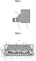
- FIG. 2 is a top view for illustrating a modification example of the leg portion 5d.
- FIG. 3 is a sectional view taken along the line III-III of FIG. 2 .
- the leg portion 5d is formed so that a thickness of a connection portion between the leg portion 5d and the case member 5b is increased from the leg portion 5d toward the case member 5b.
- the leg portion 5d thus shaped reinforces a side wall of the case member 5b. With this configuration, deformation and the fatigue fracture of each leg portion 5d can be suppressed.
- FIG. 4 is a view for illustrating a power conversion device 200 according to a second embodiment of the present invention.
- the power conversion device 200 of the second embodiment differs from that of the first embodiment in that the bus bar 5a of the smoothing capacitor 5 has a bent portion 5g.
- Other components are similar to those of the first embodiment.
- the bus bar 5a used to connect the smoothing capacitor 5 and the DC input terminal 4a is formed with a plate thickness of 1.8 mm so as to have a bent portion 5g.
- the temperatures of the smoothing capacitor 5 and the support case 4 rise during a high-load operation after startup, leading to a large temperature difference with the heat sink 2.
- a large difference occurs between a total thermal expansion amount of each boss portion 2b and each leg portion 5d and a total amount of the support case 4 and the bus bar 5a, with the result that the bus bar 5a is elongated, to thereby apply stress to the leg portions 5d.
- the bus bar 5a is formed to have a small plate thickness so as to have the bent portion 5g, and the thermal expansion amount of the bus bar 5a can thus be covered by the bent portion 5g.
- a load on each leg portion 5d can be reduced.
- the screw 6a used to fix the bus bar 5a to the support case 4 can be less loosened.
- the power conversion device 200 of the second embodiment when Lk represents a distance from the upper surface 2a of the heat sink 2 to an upper surface corresponding to a mounting surface of the substrate 3, a relationship of Lh ⁇ Lk is established between the distance Lk and the height Lh from the upper surface 2a of the heat sink 2 to the seat 2c of each boss portion.
- the mounting surface of the substrate 3 is located at a position higher than the seat 2c of each boss portion 2b.
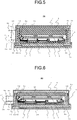
- FIG. 5 is a view for illustrating a power conversion device 300 according to a third embodiment of the present invention.
- the power conversion device 300 of the third embodiment differs from that of the first embodiment in that a metal interstage sleeve 9 is arranged between each leg portion 5d of the case member 5b and each boss portion 2b.
- Other components are similar to those of the first embodiment.
- a corresponding leg portion 5d of the case member 5b of the smoothing capacitor 5 is fixed to a corresponding boss portion 2b extending from the heat sink 2 via a corresponding metal interstage sleeve 9.
- ⁇ h represents a linear expansion coefficient of each boss portion 2b
- Lh is a height from the upper surface 2a of the heat sink 2 to the seat 2c of each boss portion
- ⁇ s represents a linear expansion coefficient of each interstage sleeve 9
- Ls represents a length of each interstage sleeve 9
- ar represents a linear expansion coefficient of the support case 4
- Lr represents a distance from the upper surface 2a of the heat sink 2 to the center 4e of the screw hole of the support case 4
- ⁇ b represents a linear expansion coefficient of the bus bar 5a
- Lb represents a distance from the open end 5e of the case member 5b to the center 4e of the screw hole
- Lc represents a distance from the open end 5e of the case member 5b to a contact surface 9a between the collar 5c of each leg portion 5d and each interstage sleeve 9
- ⁇ c represents a linear expansion coefficient of a casting resin to be filled into the case member 5b
- the support case 4, and the case member 5b and each leg portion 5d are made of the PPS resin (polyphenylene sulfide resin) having the linear expansion coefficient of 20 ⁇ 10 -6 (1/K) and the heat sink 2 and each boss portion 2b are made of ADC12 (aluminum die cast) having the linear expansion coefficient of 21 ⁇ 10 -6 (1/K).
- the bus bar 5a of the smoothing capacitor 5 is made of aluminum having the linear expansion coefficient of from 23 ⁇ 10 -6 (1/K) to 24 ⁇ 10 -6 (1/K), and each interstage sleeve is made of brass having a linear expansion coefficient of 20.8 ⁇ 10 -6 (1/K).
- the linear expansion coefficients of the individual components satisfy a relationship of ⁇ r(support case 4, case member 5b, and leg portion 5d) ⁇ s(interstage sleeve 9) ⁇ h(boss portion 2b) ⁇ b(bus bar 5a).
- the boss portions 2b are formed by cast molding and therefore limited in terms of formable height and shape due to a structure and draft of a mold.
- the interstage sleeves 9, which are formed by cutting or drawing metal have some degree of freedom in shape.
- the long interstage sleeve 9 is inserted between each leg portion 5d and each boss portion 2b so as to reduce the height of each boss portion 2b.
- the bus bar 5a of the smoothing capacitor 5 is made of aluminum having a linear expansion coefficient of from 23 ⁇ 10 -6 (1/K) to 24 ⁇ 10 -6 (1/K), and each interstage sleeve 9 is made of brass having a linear expansion coefficient of 20.8 ⁇ 10 -6 (1/K), but the materials thereof are not limited thereto.
- the bus bar 5a of the smoothing capacitor 5 may be made of oxygen-free copper having a linear expansion coefficient of 17.6 ⁇ 10 -6 (1/K), and each interstage sleeve 9 may be made of SUS304 having a linear expansion coefficient of 17.3 ⁇ 10 -6 (1/K).
- the bus bar 5a and the interstage sleeves 9 are formed of materials having almost the same linear expansion coefficient so as not to have a difference in expansion/contraction amount therebetween. With this configuration, as in a power conversion device 400 according to a first modification as illustrated in FIG. 6 , the bus bar 5a and each interstage sleeve 9 can have the same length.
- the interstage sleeve 9 is inserted between each leg portion 5d and each boss portion 2b, but the configuration is not limited thereto.
- extension screws 11 may be used instead of the interstage sleeves 9. With the extension screws 11, it is not required to hold the interstage sleeves 9 during assembly of the power conversion device 500, to thereby facilitate the assembly.
- the linear expansion coefficient of the interstage sleeves 9 is at least 1.7 times higher than that of the screw 6b.
- the load is applied onto the seat 2c of each boss portion 2b, and, in some cases, a corresponding screw 6b is loosened.
- the screw 6b can be less loosened through use of the extension screws 11 having a linear expansion coefficient equivalent to that of the screws 6b instead of the interstage sleeves 9 of the power conversion device 300.
- each interstage sleeve 9 may be set smaller than that of each collar 5c. With this setting, when each collar 5c and each interstage sleeve 9 move in opposing directions with respect to the screw 6b, a contact area between each collar 5c and each interstage sleeve 9 can be less reduced. Thus, it is possible to suppress an increase in contact pressure at the contact surface 9a between the collar 5c of each leg portion 5d and each interstage sleeve 9, which occurs due to a difference in linear expansion coefficient between the screw 6b, the collar 5c, and the interstage sleeve 9, so as to prevent the screw 6b from loosening.
- the interstage sleeves 9 each have a cylindrical shape, but the shape is not limited thereto.
- the interstage sleeves 9 may each have a shape illustrated in FIG. 8 and FIG. 9.
- FIG. 8 is a top view for illustrating the leg portion 5d.
- FIG. 9 is a sectional view taken along the line IX-IX of FIG. 8 .
- each interstage sleeve 9 is formed to have a flange portion 9b at an end portion thereof, and each leg portion 5d is formed to have a protrusion 5h.
- a clip 12 is engaged with the protrusion 5h of the leg portion 5d and the flange portion 9b of the interstage sleeve 9 while the screw 6b is being inserted in the leg portion 5d and the interstage sleeve 9.
- the interstage sleeve 9 is temporarily fixed to the leg portion 5d.
- the leg portion 5d and the interstage sleeve 9 are fixed to the boss portion 2b of the heat sink 2.
- the smoothing capacitor 5 can be fixed to the heat sink 2 while the interstage sleeve 9 is being held to the leg portion 5d during assembly of the power conversion device 300. Consequently, the assembly of the power conversion device 300 can be facilitated.
- 1 power semiconductor element 1a relay terminal, 2 heat sink, 2a upper surface, 2b boss portion, 2c seat, 2e cooling water passage, 3 substrate, 4 support case, 4a DC input terminal, 4b AC output terminal, 4c bus bar, 4e center of screw hole, 5 smoothing capacitor, 5a bus bar, 5b case member, 5c collar, 5d leg portion, 5e open end, 5g bent portion, 5h protrusion, 6a, 6b screw, 7 housing, 9 interstage sleeve, 9a contact surface, 9b flange portion, 10 center line, 11 extension screw, 12 clip, 20 metal plate, 100, 200, 300, 400 power conversion device
Landscapes
- Engineering & Computer Science (AREA)
- Microelectronics & Electronic Packaging (AREA)
- Power Engineering (AREA)
- Physics & Mathematics (AREA)
- Thermal Sciences (AREA)
- Inverter Devices (AREA)
Abstract
Description
- The present invention relates to a power conversion device having a mounting mechanism for a smoothing capacitor, which is not affected by a difference in thermal shrinkage amount between the smoothing capacitor and a housing configured to receive the smoothing capacitor.
- In recent years, development and marketing of vehicles such as electric vehicles, hybrid vehicles, and fuel-cell vehicles have been rapidly advanced from the viewpoints of environmental protection and high fuel efficiency. Those vehicles are electrically powered unlike the related-art vehicles that are powered by an internal combustion engine. In those vehicles, a power conversion device configured to convert electricity to power is mounted.
- The power conversion device includes a housing that holds therein a water-cooled heat sink, a control circuit board, a step-up converter, and other such components. The water-cooled heat sink is adapted to cool a heat generating element, for example, a switching element. The housing further includes a smoothing capacitor configured to control a ripple current, a power supply connection terminal block, a motor connection terminal block, and other such components. Those components are electrically connected together via a high- or low-voltage bus bar or a high- or low-voltage harness.
- The power conversion device thus equipped with many components is required to satisfy requirements for size reduction, weight reduction, cost reduction, high vibration resistance, and ease of assembly. For that purpose, the following configuration is proposed. That is, the individual components are attached to a housing and a cover member, which constitute a structural member. The cover member is fastened to the housing and then electrically connected thereto via a service hole formed in the housing (see
Patent Literature 1, for example). - Further, in order to achieve a high power output power conversion device, the smoothing capacitor is required to have a large capacity and withstand high voltage. In order to increase a capacity of the power conversion device, it is required to increase the number of capacitor elements or increase a size thereof . Further, in order to increase a withstand voltage of the power conversion device, it is required to increase a thickness of an insulating resin applied to cover the capacitor elements. For that purpose, a large case member is required for the smoothing capacitor.
- [PTL 1]
JP 2011-163148 A - However, when fixing a large smoothing capacitor to an inner wall of a metal housing, there is a difference in linear expansion coefficient between the metal housing and the smoothing capacitor, and hence stress is concentratedly applied between resin leg portions provided to fix the smoothing capacitor to the housing. The concentrated stress may possibly cause a fatigue fracture of the resin leg portions or loosening of a screw. Further, when a vehicle drives through a puddle of water with a power conversion device being at high temperature, there is a risk of the metal housing thereof being rapidly cooled by a large quantity of splashed water. Under such circumstances, a difference in thermal shrinkage amount between the housing and the smoothing capacitor is further increased due to a difference in thermal transfer coefficient and a difference in heat capacity in addition to the difference in linear expansion coefficient between the housing and the smoothing capacitor.
- The present invention has been made with a view to solving the above-mentioned problems. The present invention relates to a power conversion device having a mounting mechanism for a smoothing capacitor, which is not affected by the difference in thermal shrinkage amount between the smoothing capacitor and the housing configured to receive the smoothing capacitor.
- According to one embodiment of the present invention, there is provided a power conversion device including, in a housing: power semiconductor elements; a support case, to which a DC input terminal and an AC output terminal are attached, the DC input terminal and the AC output terminal being connected to the power semiconductor elements, a heat sink, in which a plurality of boss portions are formed on an upper surface thereof, and to which the power semiconductor elements and the support case are attached; a smoothing capacitor including a case member having a plurality of leg portions; and a bus bar configured to connect the smoothing capacitor and the DC input terminal, wherein, in the power conversion device in which the plurality of leg portions of the case member of the smoothing capacitor being respectively fixed to the plurality of boss portions of the heat sink, materials and dimensions of the respective boss portions, the respective leg portions, the support case, and the bus bar are determined so that a total thermal expansion/contraction amount of the respective boss portions and the respective leg portions falls within a range of from 0.9 to 1.1 relative to a total thermal expansion/contraction amount of the support case and the bus bar.
- According to the power conversion device of the present invention, the smoothing capacitor is supported not to come into direct contact with the housing so as to prevent the smoothing capacitor from being rapidly cooled even in such a situation that the housing is likely to rapidly cool from a high-temperature state. This configuration enables a power conversion device that causes no fatigue fracture of the leg portions of the case member configured to support the smoothing capacitor and also causes no loosening of a screw used to fix the case member.
-
-
FIG. 1 is a vertical sectional view for illustrating a power conversion device according to a first embodiment of the present invention. -
FIG. 2 is a top view for illustrating a modification example of a leg portion in the first embodiment. -
FIG. 3 is a sectional view taken along the line III-III ofFIG.2 . -
FIG. 4 is a vertical sectional view for illustrating a power conversion device according to a second embodiment of the present invention. -
FIG. 5 is a vertical sectional view for illustrating a power conversion device according to a third embodiment of the present invention. -
FIG. 6 is a view for illustrating a first modification example of the power conversion device according to the third embodiment. -
FIG. 7 is a view for illustrating a second modification example of the power conversion device according to the third embodiment. -
FIG. 8 is a top view for illustrating a modification example of an interstage sleeve in the third embodiment. -
FIG. 9 is a sectional view taken along the line IX-IX ofFIG. 8 . - Now, with reference to the drawings, a power conversion device according to exemplary embodiments of the present invention is described.
-
FIG. 1 is a configuration view for illustrating apower conversion device 100 according to a first embodiment of the present invention. As illustrated inFIG. 1 , thepower conversion device 100 of the first embodiment includes ahousing 7 fixed onto an upper surface 2a of a water-cooledheat sink 2 having a cooling water passage 2e. Thepower conversion device 100 includes, in thehousing 7, a plurality ofpower semiconductor elements 1, asubstrate 3 configured to control and drive thepower semiconductor elements 1, and asupport case 4, to which a DC input terminal 4a and an AC output terminal 4b are attached. The DC input terminal 4a and the AC output terminal 4b are to be electrically connected topower semiconductor elements 1. - The plurality of
power semiconductor elements 1 are arranged on the upper surface 2a of theheat sink 2 . Relay terminals 1a extending upward from thepower semiconductor elements 1 are electrically connected to thesubstrate 3 arranged above thepower semiconductor elements 1. Further, on the upper surface 2a of theheat sink 2, asupport case 4 is arranged, in which bus bar 4c are formed by insert molding. The bus bar 4c serves to electrically connect the DC input terminal 4a and each of thepower semiconductor elements 1 as well as to electrically connect each of thepower semiconductor elements 1 and the AC output terminal 4b. In addition, ametal plate 20 is arranged above thesupport case 4 so as to shield thesubstrate 3 against magnetic noise generated from thepower semiconductor elements 1 so that a circuit on thesubstrate 3 is free from the noise. - A
smoothing capacitor 5 covered by a case member 5b is arranged above thesubstrate 3 across an interval. Further, thesupport case 4, to which the DC input terminal 4a and the AC output terminal 4b are attached, is arranged below the substrate. - The
smoothing capacitor 5 is electrically connected to the DC input terminal 4a via a bus bar 5a extending downward from an open end 5e on a lower side of the case member 5b. The bus bar 5a and the DC input terminal 4a are fixed to thesupport case 4 by means of a screw 6a. Further, a ground bus bar terminal 5f of a Y capacitor incorporated in thesmoothing capacitor 5 is fixed to a corresponding boss portion 2b together with a corresponding leg portion 5d by means of a corresponding screw 6b. - The case member 5b of the
smoothing capacitor 5 has, on a side surface thereof, a plurality of leg portions 5d. The plurality of leg portions 5d are formed integrally with the case member 5b. Also, each leg portion 5d has a metal collar 5c that is formed by insert molding. Theheat sink 2 has a plurality of the boss portions 2b extending from the upper surface 2a of theheat sink 2 to thesmoothing capacitor 5. The plurality of leg portions 5d of thesmoothing capacitor 5 are fixed to the plurality of boss portions 2b by means of the screws 6b in a one-to-one correspondence. As described above, thesmoothing capacitor 5 is fixed to the plurality of boss portions 2b extending from theheat sink 2, via the plurality of leg portions 5d of the case member 5b in which thesmoothing capacitor 5 is accommodated. Thus, the smoothingcapacitor 5 is not in contact with thehousing 7. - When αh represents a linear expansion coefficient of each boss portion 2b, Lh is a height from the upper surface 2a of the
heat sink 2 to a seat 2c of each boss portion, αs is linear expansion coefficients of the case member 5b and each leg portion 5d, Ls represents a length of each leg portion 5d extending from the case member 5b to each boss portion 2b, αr represents a linear expansion coefficient of thesupport case 4, Lr represents a distance from the upper surface 2a of theheat sink 2, on which thesupport case 4 is arranged, to a center 4e of a screw hole formed in thesupport case 4, αb represents a linear expansion coefficient of the bus bar 5a, and Lb represents a distance from the open end 5e of the case member 5b to the center 4e of the screw hole, materials and dimensions for each boss portion, each leg portion, the support case, and the bus bar are determined so that a value of (αh×Lh+αs×Ls)/(αr×Lr+αb×Lb) falls within a range of from 0.9 to 1.1. - For example, the
support case 4, and the case member 5b and each leg portion 5d are made of a PPS resin (polyphenylene sulfide resin) having a linear expansion coefficient of 20×10-6(1/K), and theheat sink 2 and each boss portion 2b are made of ADC12 (aluminum die cast) having a linear expansion coefficient of 21×10-6(1/K). Further, the bus bar 5a of the smoothingcapacitor 5 is made of aluminum having a linear expansion coefficient of from 23×10-6(1/K) to 24×10-6(1/K), and each collar 5c and each screw 6b are made of iron having a linear expansion coefficient of from 11×10-6(1/K) to 12×10-6(1/K). - In this case, linear expansion coefficients of the individual components satisfy a relationship of αr(support case 4) =αs (case member 5b and leg portion 5d) <αh (boss portion 2b) <αb (bus bar 5a). Hence, in order to keep a balance with an expansion/contraction amount of the bus bar 5a, the length Ls of each leg portion 5d is required to be decreased and the height Lh of each boss portion 2b is required to be increased. With this setting, a vibration resistance and a cooling/heating cycle stability are both ensured. Further, the ground bus bar terminal 5f of the Y capacitor becomes short, and hence noise of the smoothing
capacitor 5 can be released to theheat sink 2 on a ground side at high efficiency, leading to noise reduction. - In addition, the materials for each collar 5c and each screw 6b are selected so as to have the same linear expansion coefficient, by which an expansion/contraction amount of each collar 5c matches that of each screw 6b during a cooling/heating cycle. Consequently, the screws 6b are less loosened.
- In
FIG. 1 , although the ground bus bar terminal 5f of the Y capacitor incorporated in the smoothingcapacitor 5 is fixed to a corresponding boss portion 2b together with a corresponding leg portion 5d, the ground bus bar terminal 5f alone can be fixed to the corresponding boss portion 2b. - As described above, according to the
power conversion device 100 of the first embodiment, dimensions of the individual components are determined so that a value of ("thermal expansion amount of each boss portion" + "thermal expansion amount of each leg portion")/("thermal expansion amount of the support case" + "thermal expansion amount of the bus bar") falls within a range of from 0.9 to 1.1. With this setting, even when the smoothingcapacitor 5 reaches a high temperature and a corresponding leg portion 5d of the case member 5b of the smoothingcapacitor 5 elongates toward theheat sink 2 side, stress is less likely to concentrate on the leg portion 5d, to thereby prevent a fatigue fracture of the leg portion 5d and also prevent the screw 6b from loosening. - Further, when a vehicle drives through a puddle of water with the
power conversion device 100 being at high temperature, there is a risk of themetal housing 7 being rapidly cooled by a large quantity of splashed water. In this case, a difference in thermal shrinkage amount between thehousing 7 and the smoothingcapacitor 5 is further increased due to a difference in thermal transfer coefficient and a difference in heat capacity in addition to the difference in linear expansion coefficient between thehousing 7 and the smoothingcapacitor 5. - Even in such circumstances, according to the
power conversion device 100 of the first embodiment, the smoothingcapacitor 5 is supported so as not to come into contact with thehousing 7, and hence the smoothingcapacitor 5 is not rapidly cooled. It is therefore possible to avoid such a situation that the smoothingcapacitor 5 is rapidly cooled, to thereby cause stress concentration in between the leg portions 5d, a fatigue fracture of the leg portions 5d, and loosening of the screw 6b. - Further, the smoothing
capacitor 5 is not fixed to thehousing 7, and hence thehousing 7 can be prepared by processing a metal sheet. This configuration allows reduction in weight and processing cost of thehousing 7. As another effect of the configuration described above, vibrations generated during the operation of the smoothingcapacitor 5 do not directly propagate to thehousing 7, and consequently the operation noise, generated by the smoothingcapacitor 5, rarely leaks to an outside of thehousing 7. - Moreover, even when the smoothing
capacitor 5 reaches high temperature due to high-load running after cold start, and the smoothingcapacitor 5 and theheat sink 2 thus have a large difference of thermal expansion amount in a horizontal direction, the boss portions 2b extending from the upper surface 2a of theheat sink 2 to the smoothingcapacitor 5 warp, to thereby relax stress applied to the leg portions 5d. Accordingly, it is possible to prevent the fatigue fracture of the leg portions 5d and loosening of the screw 6b. - In addition, each boss portion 2b is formed so as to protrude from the upper surface 2a of the
heat sink 2 so that a female thread portion formed by machining in the boss portion 2b does not interfere with the cooling water passage 2e of theheat sink 2. With this arrangement, the number of boss portions 2b and the layout thereof can be freely selected. In addition, owing to the large thickness of each boss portion 2b, each boss portion 2b can have a rigidity high enough to ensure both of a vibration resistance and a cooling/heating cycle stability. - In
FIG. 1 , the seat 2c of each boss portion 2b is located at a position lower than the open end 5e of the case member 5b, but the position is not limited thereto. For example, the length Ls of each leg portion 5d may be set to zero so that the seat 2c of each boss portion 2b is located above the open end 5e of the case member 5b. - Further, in
FIG. 1 , each leg portion 5d is formed into an L shape but the shape is not limited thereto.FIG. 2 is a top view for illustrating a modification example of the leg portion 5d.FIG. 3 is a sectional view taken along the line III-III ofFIG. 2 . For example, as illustrated inFIG. 2 andFIG. 3 , the leg portion 5d is formed so that a thickness of a connection portion between the leg portion 5d and the case member 5b is increased from the leg portion 5d toward the case member 5b. The leg portion 5d thus shaped reinforces a side wall of the case member 5b. With this configuration, deformation and the fatigue fracture of each leg portion 5d can be suppressed. -
FIG. 4 is a view for illustrating apower conversion device 200 according to a second embodiment of the present invention. Thepower conversion device 200 of the second embodiment differs from that of the first embodiment in that the bus bar 5a of the smoothingcapacitor 5 has a bent portion 5g. Other components are similar to those of the first embodiment. - As illustrated in
FIG. 4 , in thepower conversion device 200 of the second embodiment, the bus bar 5a used to connect the smoothingcapacitor 5 and the DC input terminal 4a, is formed with a plate thickness of 1.8 mm so as to have a bent portion 5g. - In the
power conversion device 200, the temperatures of the smoothingcapacitor 5 and thesupport case 4 rise during a high-load operation after startup, leading to a large temperature difference with theheat sink 2. In this case, a large difference occurs between a total thermal expansion amount of each boss portion 2b and each leg portion 5d and a total amount of thesupport case 4 and the bus bar 5a, with the result that the bus bar 5a is elongated, to thereby apply stress to the leg portions 5d. - Even in such a case, according to the
power conversion device 200 of the second embodiment, the bus bar 5a is formed to have a small plate thickness so as to have the bent portion 5g, and the thermal expansion amount of the bus bar 5a can thus be covered by the bent portion 5g. With this configuration, a load on each leg portion 5d can be reduced. Moreover, the screw 6a used to fix the bus bar 5a to thesupport case 4 can be less loosened. - Further, as illustrated in
FIG. 4 , according to thepower conversion device 200 of the second embodiment, when Lk represents a distance from the upper surface 2a of theheat sink 2 to an upper surface corresponding to a mounting surface of thesubstrate 3, a relationship of Lh<Lk is established between the distance Lk and the height Lh from the upper surface 2a of theheat sink 2 to the seat 2c of each boss portion. As a result, the mounting surface of thesubstrate 3 is located at a position higher than the seat 2c of each boss portion 2b. Thus, in a step of soldering the relay terminals 1a of thepower semiconductor elements 1 to thesubstrate 3, the length of a nozzle zig for partial spraying can be reduced to thereby improve solderability. -
FIG. 5 is a view for illustrating apower conversion device 300 according to a third embodiment of the present invention. Thepower conversion device 300 of the third embodiment differs from that of the first embodiment in that a metalinterstage sleeve 9 is arranged between each leg portion 5d of the case member 5b and each boss portion 2b. Other components are similar to those of the first embodiment. - As illustrated in
FIG. 5 , in thepower conversion device 300 of the third embodiment, a corresponding leg portion 5d of the case member 5b of the smoothingcapacitor 5 is fixed to a corresponding boss portion 2b extending from theheat sink 2 via a corresponding metal interstagesleeve 9. - Thus, in the thus-configured power conversion device 300 of the third embodiment, when αh represents a linear expansion coefficient of each boss portion 2b, Lh is a height from the upper surface 2a of the heat sink 2 to the seat 2c of each boss portion, αs represents a linear expansion coefficient of each interstage sleeve 9, Ls represents a length of each interstage sleeve 9, ar represents a linear expansion coefficient of the support case 4, Lr represents a distance from the upper surface 2a of the heat sink 2 to the center 4e of the screw hole of the support case 4, αb represents a linear expansion coefficient of the bus bar 5a, Lb represents a distance from the open end 5e of the case member 5b to the center 4e of the screw hole, Lc represents a distance from the open end 5e of the case member 5b to a contact surface 9a between the collar 5c of each leg portion 5d and each interstage sleeve 9, and αc represents a linear expansion coefficient of a casting resin to be filled into the case member 5b, materials and dimensions of each boss portion, each interstage sleeve, the support case, and the bus bar are determined so that a value of (αh×Lh+αs×Ls)/(αr×Lr+αb×Lb+αc×Lc) falls within a range of from 0.9 to 1.1.
- For example, the
support case 4, and the case member 5b and each leg portion 5d are made of the PPS resin (polyphenylene sulfide resin) having the linear expansion coefficient of 20×10-6(1/K) and theheat sink 2 and each boss portion 2b are made of ADC12 (aluminum die cast) having the linear expansion coefficient of 21×10-6(1/K). Further, the bus bar 5a of the smoothingcapacitor 5 is made of aluminum having the linear expansion coefficient of from 23×10-6 (1/K) to 24×10-6(1/K), and each interstage sleeve is made of brass having a linear expansion coefficient of 20.8×10⁻⁶(1/K). - In this case, the linear expansion coefficients of the individual components satisfy a relationship of αr(
support case 4, case member 5b, and leg portion 5d)≈αs(interstage sleeve 9)<αh(boss portion 2b)<αb(bus bar 5a). Thus, in order to keep a balance with the expansion/contraction amount of the bus bar 5a, it is required to increase the length Ls of eachinterstage sleeve 9 or the height Lh of each boss portion 2b. - However, the boss portions 2b are formed by cast molding and therefore limited in terms of formable height and shape due to a structure and draft of a mold. In contrast, the
interstage sleeves 9, which are formed by cutting or drawing metal, have some degree of freedom in shape. Thus, in thepower conversion device 300 of the third embodiment, the longinterstage sleeve 9 is inserted between each leg portion 5d and each boss portion 2b so as to reduce the height of each boss portion 2b. This arrangement allows improvement in moldability of theheat sink 2 that is produced integrally with the boss portions 2b, and allows downsizing of the mold so that a molding cost can be reduced and both of a vibration resistance and a cooling/heating cycle stability can be obtained with ease. - Note that, in the
power conversion device 300 of the third embodiment, the bus bar 5a of the smoothingcapacitor 5 is made of aluminum having a linear expansion coefficient of from 23×10-6(1/K) to 24×10-6(1/K), and eachinterstage sleeve 9 is made of brass having a linear expansion coefficient of 20.8×10⁻⁶(1/K), but the materials thereof are not limited thereto. For example, the bus bar 5a of the smoothingcapacitor 5 may be made of oxygen-free copper having a linear expansion coefficient of 17.6×10⁻⁶(1/K), and eachinterstage sleeve 9 may be made of SUS304 having a linear expansion coefficient of 17.3×10⁻⁶(1/K). - The bus bar 5a and the
interstage sleeves 9 are formed of materials having almost the same linear expansion coefficient so as not to have a difference in expansion/contraction amount therebetween. With this configuration, as in apower conversion device 400 according to a first modification as illustrated inFIG. 6 , the bus bar 5a and eachinterstage sleeve 9 can have the same length. - Further, in the
power conversion device 300 of the third embodiment, theinterstage sleeve 9 is inserted between each leg portion 5d and each boss portion 2b, but the configuration is not limited thereto. For example, as in apower conversion device 500 in a second modification example as illustrated inFIG. 7 , extension screws 11 may be used instead of theinterstage sleeves 9. With the extension screws 11, it is not required to hold theinterstage sleeves 9 during assembly of thepower conversion device 500, to thereby facilitate the assembly. - Moreover, when the screw 6b is formed of inexpensive iron having a linear expansion coefficient of from 11×10-6(1/K) to 12×10-6(1/K), the linear expansion coefficient of the
interstage sleeves 9 is at least 1.7 times higher than that of the screw 6b. As a result, the load is applied onto the seat 2c of each boss portion 2b, and, in some cases, a corresponding screw 6b is loosened. Even in such a case, in thepower conversion device 500 ofFIG. 5 , the screw 6b can be less loosened through use of the extension screws 11 having a linear expansion coefficient equivalent to that of the screws 6b instead of theinterstage sleeves 9 of thepower conversion device 300. - Further, the inner diameter of each
interstage sleeve 9 may be set smaller than that of each collar 5c. With this setting, when each collar 5c and eachinterstage sleeve 9 move in opposing directions with respect to the screw 6b, a contact area between each collar 5c and eachinterstage sleeve 9 can be less reduced. Thus, it is possible to suppress an increase in contact pressure at the contact surface 9a between the collar 5c of each leg portion 5d and eachinterstage sleeve 9, which occurs due to a difference in linear expansion coefficient between the screw 6b, the collar 5c, and theinterstage sleeve 9, so as to prevent the screw 6b from loosening. - Further, in the third embodiment, the
interstage sleeves 9 each have a cylindrical shape, but the shape is not limited thereto. For example, theinterstage sleeves 9 may each have a shape illustrated inFIG. 8 and FIG. 9. FIG. 8 is a top view for illustrating the leg portion 5d.FIG. 9 is a sectional view taken along the line IX-IX ofFIG. 8 . - As illustrated in
FIG. 8 and FIG. 9 , eachinterstage sleeve 9 is formed to have a flange portion 9b at an end portion thereof, and each leg portion 5d is formed to have a protrusion 5h. Then, as illustrated inFIG. 9 , aclip 12 is engaged with the protrusion 5h of the leg portion 5d and the flange portion 9b of theinterstage sleeve 9 while the screw 6b is being inserted in the leg portion 5d and theinterstage sleeve 9. Then, theinterstage sleeve 9 is temporarily fixed to the leg portion 5d. In this state, the leg portion 5d and theinterstage sleeve 9 are fixed to the boss portion 2b of theheat sink 2. With this configuration, the smoothingcapacitor 5 can be fixed to theheat sink 2 while theinterstage sleeve 9 is being held to the leg portion 5d during assembly of thepower conversion device 300. Consequently, the assembly of thepower conversion device 300 can be facilitated. - 1 power semiconductor element, 1a relay terminal, 2 heat sink, 2a upper surface, 2b boss portion, 2c seat, 2e cooling water passage, 3 substrate, 4 support case, 4a DC input terminal, 4b AC output terminal, 4c bus bar, 4e center of screw hole, 5 smoothing capacitor, 5a bus bar, 5b case member, 5c collar, 5d leg portion, 5e open end, 5g bent portion, 5h protrusion, 6a, 6b screw, 7 housing, 9 interstage sleeve, 9a contact surface, 9b flange portion, 10 center line, 11 extension screw, 12 clip, 20 metal plate, 100, 200, 300, 400 power conversion device
Claims (16)
- A power conversion device comprising, in a housing:power semiconductor elements;a support case, to which a DC input terminal and an AC output terminal are attached, the DC input terminal and the AC output terminal being connected to the power semiconductor elements,a heat sink, in which a plurality of boss portions are formed on an upper surface thereof, and to which the power semiconductor elements and the support case are attached;a case member having a plurality of leg portions;a smoothing capacitor accommodated in the case member; anda bus bar configured to connect the smoothing capacitor and the DC input terminal,the plurality of leg portions of the case member being respectively fixed to the plurality of boss portions of the heat sink,wherein materials and dimensions of the respective boss portions, the respective leg portions, the support case, and the bus bar are determined so that a total thermal elongation amount of the respective boss portions and the respective leg portions falls within a range of from 0.9 to 1.1 relative to a total thermal elongation amount of the support case and the bus bar.
- A power conversion device comprising, in a housing:power semiconductor elements;a support case, to which a DC input terminal and an AC output terminal are attached, the DC input terminal and the AC output terminal being connected to the power semiconductor elements,a heat sink, in which a plurality of boss portions are formed on an upper surface thereof, and to which the power semiconductor elements and the support case are attached;a case member having a plurality of leg portions;a smoothing capacitor accommodated in the case member; anda bus bar configured to connect the smoothing capacitor and the DC input terminal,the bus bar being attached to the DC input terminal by a screw, andthe plurality of leg portions of the case member being respectively fixed to the plurality of boss portions of the heat sink,wherein materials and dimensions of the respective boss portions, the respective leg portions, the support case, and the bus bar are determined so that a value of (αh×Lh+αs×Ls)/(αr×Lr+αb×Lb) falls within a range of from 0.9 to 1.1, where:αh represents a linear expansion coefficient of the respective boss portions;Lh represents a distance from the upper surface of the heat sink to a seat of the respective boss portions;αs represents a linear expansion coefficient of the respective leg portions;Ls represents a length of the respective leg portions extending from the case member to the respective boss portions;αr represents a linear expansion coefficient of the support case;Lr represents a distance from the upper surface of the heat sink to a center of a screw hole, into which the screw is inserted;αb represents a linear expansion coefficient of the bus bar, and;Lb represents a distance from an open end of the case member to the center of the screw hole.
- The power conversion device according to claim 2, further comprising a substrate electrically connected to relay terminals of the power semiconductor elements,
wherein when Lk represents a distance from the upper surface of the heat sink to an upper surface of the substrate, a relationship of Lh<Lk is satisfied. - The power conversion device according to any one of claims 1 to 3, wherein the bus bar has a bent portion at a position between the case member and a connection portion with the DC input terminal.
- The power conversion device according to any one of claims 1 to 4,
wherein linear expansion coefficients of the support case, and the case member and the respective leg portions are smaller than linear expansion coefficients of the heat sink and the respective boss portions, and
wherein the linear expansion coefficients of the heat sink and the respective boss portions are smaller than a linear expansion coefficient of the bus bar. - The power conversion device according to claim 5,
wherein the support case, the case member, and the respective leg portions are made of a PPS resin,
wherein the heat sink and the respective boss portions are made of ADC12, and
wherein the bus bar is made of aluminum. - A power conversion device comprising, in a housing:power semiconductor elements;a support case, to which a DC input terminal and an AC output terminal are attached, the DC input terminal and the AC output terminal being connected to the power semiconductor elements,a heat sink, in which a plurality of boss portions are formed on an upper surface thereof, and to which the power semiconductor elements and the support case are attached;a case member having a plurality of leg portions;a smoothing capacitor accommodated in the case member; anda bus bar configured to connect the smoothing capacitor and the DC input terminal,the plurality of leg portions of the case member each having an integrally formed collar, andthe plurality of leg portions being respectively fixed to the plurality of boss portions of the heat sink via the collar and an intermediate member,wherein materials and dimensions of the respective boss portions, the intermediate member, the support case, and the bus bar are determined so that a total thermal elongation amount of the respective boss portions and the intermediate member falls within a range of from 0.9 to 1.1 relative to a total thermal elongation amount of the support case and the bus bar.
- A power conversion device comprising, in a housing:power semiconductor elements;a substrate electrically connected to relay terminals of the power semiconductor elements,a support case, to which a DC input terminal and an AC output terminal are attached, the DC input terminal and the AC output terminal being connected to the power semiconductor elements,a heat sink, in which a plurality of boss portions are formed on an upper surface thereof, and to which the power semiconductor elements and the support case are attached;a case member having a plurality of leg portions;a smoothing capacitor accommodated in the case member; anda bus bar configured to connect the smoothing capacitor and the DC input terminal,the plurality of leg portions of the case member each having an integrally formed collar,the plurality of leg portions being respectively fixed to the plurality of boss portions of the heat sink via the collar and an intermediate member,the bus bar being attached to the support case by a screw,the case member having a plurality of leg portions each having a collar, andthe plurality of leg portions of the case member being respectively fixed to seats of the plurality of boss portions via the collar and an intermediate member,wherein materials and dimensions of the respective boss portions, the intermediate member, the support case, and the bus bar are determined so that a value of (αh×Lh+αs×Ls)/(αr×Lr+αb×Lb+αc×Lc) falls within a range of from 0.9 to 1.1, where:αh represents a linear expansion coefficient of the respective boss portions;Lh represents a distance from the upper surface of the heat sink to the seat of the respective boss portions;αs represents a linear expansion coefficient of the intermediate member;Ls represents a length of the intermediate member, αr represents a linear expansion coefficient of the support case;Lr represents a distance from the upper surface of the heat sink to a center of a screw hole, into which the screw is inserted,αb represents a linear expansion coefficient of the bus bar;Lb represents a distance from an open end of the case member to the center of the screw hole;αc represents a linear expansion coefficient of a casting resin to be filled into the case member; andLc represents a distance from the open end of the case member to a contact surface between the collar and the intermediate member.
- The power conversion device according to claim 7 or 8,
wherein linear expansion coefficients of the support case, and the case member and the respective leg portions are smaller than a linear expansion coefficient of the intermediate member,
wherein the linear expansion coefficient of the intermediate member is smaller than linear expansion coefficients of the heat sink and the respective boss portions, and
wherein the linear expansion coefficients of the heat sink and the respective boss portions are smaller than a linear expansion coefficient of the bus bar. - The power conversion device according to claim 9,
wherein the support case, the case member, and the respective leg portions are made of PPS,
wherein the intermediate member is made of brass,
wherein the heat sink and the respective boss portions are made of ADC12, and
wherein the bus bar is made of aluminum. - The power conversion device according to claim 9,
wherein the support case is made of PPS,
wherein the intermediate member is made of SUS304,
wherein the respective boss portions are made of ADC12, and wherein the bus bar is made of oxygen-free copper. - The power conversion device according to any one of claims 7 to 11, wherein the intermediate member comprises an extension screw.
- The power conversion device according to any one of claims 7 to 11, wherein the intermediate member includes a sleeve.
- The power conversion device according to claim 13, wherein a contact surface between the sleeve and the collar is located above a center line of the case member in a vertical direction.
- The power conversion device according to claim 13 or 14, wherein an inner diameter of the sleeve is smaller than an inner diameter of the collar.
- The power conversion device according to any one of claims 1 to 15,
wherein the respective leg portions are formed integrally with the case member, and
wherein a thickness of the respective leg portions increases toward the case member.
Applications Claiming Priority (1)
| Application Number | Priority Date | Filing Date | Title |
|---|---|---|---|
| PCT/JP2017/015921 WO2018193588A1 (en) | 2017-04-20 | 2017-04-20 | Power conversion device |
Publications (3)
| Publication Number | Publication Date |
|---|---|
| EP3614550A1 true EP3614550A1 (en) | 2020-02-26 |
| EP3614550A4 EP3614550A4 (en) | 2020-04-29 |
| EP3614550B1 EP3614550B1 (en) | 2021-02-17 |
Family
ID=63856778
Family Applications (1)
| Application Number | Title | Priority Date | Filing Date |
|---|---|---|---|
| EP17905941.5A Active EP3614550B1 (en) | 2017-04-20 | 2017-04-20 | Power conversion device |
Country Status (5)
| Country | Link |
|---|---|
| US (1) | US11019756B2 (en) |
| EP (1) | EP3614550B1 (en) |
| JP (1) | JP6818877B2 (en) |
| CN (1) | CN110506385B (en) |
| WO (1) | WO2018193588A1 (en) |
Families Citing this family (7)
| Publication number | Priority date | Publication date | Assignee | Title |
|---|---|---|---|---|
| CA3067320C (en) * | 2017-06-15 | 2020-06-23 | Nissan Motor Co., Ltd. | Power conversion device |
| JP7363261B2 (en) * | 2019-09-19 | 2023-10-18 | 株式会社デンソー | power converter |
| JP6854874B1 (en) * | 2019-12-11 | 2021-04-07 | 三菱電機株式会社 | Power converter |
| WO2021166611A1 (en) * | 2020-02-19 | 2021-08-26 | 三菱電機株式会社 | Power conversion device |
| JP7517143B2 (en) | 2020-12-28 | 2024-07-17 | トヨタ自動車株式会社 | Reactor Unit |
| JP7183373B1 (en) * | 2021-11-15 | 2022-12-05 | 三菱電機株式会社 | power converter |
| CN115474403B (en) * | 2022-08-26 | 2025-03-04 | 华为数字能源技术有限公司 | Electronic devices and photovoltaic power optimizers |
Family Cites Families (27)
| Publication number | Priority date | Publication date | Assignee | Title |
|---|---|---|---|---|
| US5821617A (en) * | 1996-07-29 | 1998-10-13 | Microsemi Corporation | Surface mount package with low coefficient of thermal expansion |
| DE19645636C1 (en) * | 1996-11-06 | 1998-03-12 | Telefunken Microelectron | Power module for operating electric motor with speed and power control |
| JP3881502B2 (en) * | 2000-01-28 | 2007-02-14 | 株式会社東芝 | Power semiconductor module |
| JP3645475B2 (en) * | 2000-08-24 | 2005-05-11 | 株式会社東芝 | Inverter device |
| JP4476465B2 (en) * | 2000-10-04 | 2010-06-09 | 三菱電機株式会社 | Power converter |
| DE10129788B4 (en) * | 2001-06-20 | 2005-11-10 | Siemens Ag | Plastic frame for mounting an electronic power control unit |
| US7492594B2 (en) | 2007-05-03 | 2009-02-17 | Hamilton Sundstrand Corporation | Electronic circuit modules cooling |
| JP5314933B2 (en) * | 2008-06-02 | 2013-10-16 | 本田技研工業株式会社 | Power converter |
| JP5002568B2 (en) * | 2008-10-29 | 2012-08-15 | 日立オートモティブシステムズ株式会社 | Power converter |
| JP5517652B2 (en) | 2010-02-05 | 2014-06-11 | 三菱重工業株式会社 | Inverter-integrated electric compressor and assembly method thereof |
| US9338925B2 (en) * | 2010-10-27 | 2016-05-10 | Mitsubishi Electric Corporation | Device for controlling drive of motor for electric power steering device |
| JP5351907B2 (en) * | 2011-01-13 | 2013-11-27 | アイシン・エィ・ダブリュ株式会社 | Semiconductor device |
| WO2012105353A1 (en) * | 2011-01-31 | 2012-08-09 | トヨタ自動車株式会社 | Mounting structure for power control unit |
| EP2688378B1 (en) * | 2011-03-16 | 2016-03-16 | Toyota Jidosha Kabushiki Kaisha | Substrate unit |
| EP2790216B1 (en) * | 2011-12-08 | 2020-01-22 | Fuji Electric Co., Ltd. | Semiconductor device and semiconductor device manufacturing method |
| CN104704629A (en) * | 2012-10-16 | 2015-06-10 | 富士电机株式会社 | Cooling structure and heat generating body |
| CN104838493B (en) * | 2012-11-28 | 2017-07-14 | 三菱电机株式会社 | power module |
| KR101466032B1 (en) * | 2013-08-02 | 2014-11-28 | 엘에스산전 주식회사 | Inverter |
| JP6139330B2 (en) * | 2013-08-23 | 2017-05-31 | 三菱電機株式会社 | Power semiconductor device |
| JP6503807B2 (en) * | 2014-05-19 | 2019-04-24 | 株式会社三洋物産 | Gaming machine |
| DE112015006036B4 (en) * | 2015-01-23 | 2023-09-28 | Mitsubishi Electric Corporation | ENGINE DRIVE CONTROL DEVICE FOR ELECTRIC POWER STEERING |
| CN106332499A (en) * | 2015-06-26 | 2017-01-11 | 台达电子工业股份有限公司 | A package assembly, electronic equipment for chip power supply |
| JP6634722B2 (en) * | 2015-07-14 | 2020-01-22 | 富士電機株式会社 | Insulating busbar and manufacturing method |
| JP6292528B2 (en) * | 2016-08-05 | 2018-03-14 | パナソニックIpマネジメント株式会社 | Inverter |
| CN106505837A (en) | 2016-12-30 | 2017-03-15 | 天津安捷励电控技术有限责任公司 | Current transformation module |
| WO2019077722A1 (en) * | 2017-10-19 | 2019-04-25 | 三菱電機株式会社 | Waterproof connector and method for assembling same |
| JP6457678B1 (en) * | 2018-03-19 | 2019-01-23 | 株式会社ケーヒン | Power converter |
-
2017
- 2017-04-20 WO PCT/JP2017/015921 patent/WO2018193588A1/en not_active Ceased
- 2017-04-20 EP EP17905941.5A patent/EP3614550B1/en active Active
- 2017-04-20 CN CN201780089492.8A patent/CN110506385B/en active Active
- 2017-04-20 US US16/496,507 patent/US11019756B2/en active Active
- 2017-04-20 JP JP2019513168A patent/JP6818877B2/en active Active
Also Published As
| Publication number | Publication date |
|---|---|
| JPWO2018193588A1 (en) | 2019-07-11 |
| US11019756B2 (en) | 2021-05-25 |
| WO2018193588A1 (en) | 2018-10-25 |
| JP6818877B2 (en) | 2021-01-20 |
| EP3614550B1 (en) | 2021-02-17 |
| US20210112689A1 (en) | 2021-04-15 |
| EP3614550A4 (en) | 2020-04-29 |
| CN110506385A (en) | 2019-11-26 |
| CN110506385B (en) | 2021-03-12 |
Similar Documents
| Publication | Publication Date | Title |
|---|---|---|
| US11019756B2 (en) | Power conversion device | |
| KR100991336B1 (en) | Control device for vehicle | |
| US8391005B2 (en) | Frequency converter on a motor | |
| US20170311457A1 (en) | Electric connection box | |
| US20180026381A1 (en) | Electrical connection box and connection terminal component | |
| US20220263305A1 (en) | Circuit structure | |
| US10477709B2 (en) | Housing and rubber plug for power conversion equipment | |
| US9693476B2 (en) | Power conversion apparatus | |
| EP3109957B1 (en) | Power distribution panel having contactor with thermal management feature | |
| KR20220098116A (en) | Dc-dc converter | |
| JP6289753B2 (en) | Power converter housing and resin cap | |
| CN112615466A (en) | Three-phase sealing structure of oil-cooled motor | |
| JP6760691B1 (en) | Power converter | |
| JP2013106473A (en) | Inverter device and electric driving system | |
| US20220377948A1 (en) | Power converter | |
| EP3109956B1 (en) | Aircraft power distribution panel having thermal management feature | |
| CN110800384B (en) | Component assembly and method of making such assembly | |
| JP4321459B2 (en) | Busbar mounting structure to heat dissipation plate | |
| WO2018143053A1 (en) | Power conversion device | |
| JP2019103280A (en) | Power conversion device | |
| JP7814282B2 (en) | Power Conversion Device | |
| CN221728099U (en) | A permanent magnet motor and controller integrated structure | |
| CN112737283A (en) | Power conversion device | |
| WO2020201799A1 (en) | Power conversion device | |
| US12476060B2 (en) | Circuit assembly |
Legal Events
| Date | Code | Title | Description |
|---|---|---|---|
| STAA | Information on the status of an ep patent application or granted ep patent |
Free format text: STATUS: THE INTERNATIONAL PUBLICATION HAS BEEN MADE |
|
| PUAI | Public reference made under article 153(3) epc to a published international application that has entered the european phase |
Free format text: ORIGINAL CODE: 0009012 |
|
| STAA | Information on the status of an ep patent application or granted ep patent |
Free format text: STATUS: REQUEST FOR EXAMINATION WAS MADE |
|
| 17P | Request for examination filed |
Effective date: 20191001 |
|
| AK | Designated contracting states |
Kind code of ref document: A1 Designated state(s): AL AT BE BG CH CY CZ DE DK EE ES FI FR GB GR HR HU IE IS IT LI LT LU LV MC MK MT NL NO PL PT RO RS SE SI SK SM TR |
|
| AX | Request for extension of the european patent |
Extension state: BA ME |
|
| REG | Reference to a national code |
Ref country code: DE Ref legal event code: R079 Ref document number: 602017033036 Country of ref document: DE Free format text: PREVIOUS MAIN CLASS: H02M0007480000 Ipc: H02M0007000000 |
|
| A4 | Supplementary search report drawn up and despatched |
Effective date: 20200327 |
|
| RIC1 | Information provided on ipc code assigned before grant |
Ipc: H02M 7/00 20060101AFI20200324BHEP Ipc: H05K 7/20 20060101ALI20200324BHEP Ipc: H01L 23/473 20060101ALI20200324BHEP Ipc: H01L 25/07 20060101ALI20200324BHEP Ipc: H05K 7/14 20060101ALI20200324BHEP Ipc: H02M 7/48 20070101ALI20200324BHEP |
|
| DAV | Request for validation of the european patent (deleted) | ||
| DAX | Request for extension of the european patent (deleted) | ||
| GRAP | Despatch of communication of intention to grant a patent |
Free format text: ORIGINAL CODE: EPIDOSNIGR1 |
|
| STAA | Information on the status of an ep patent application or granted ep patent |
Free format text: STATUS: GRANT OF PATENT IS INTENDED |
|
| INTG | Intention to grant announced |
Effective date: 20201006 |
|
| GRAS | Grant fee paid |
Free format text: ORIGINAL CODE: EPIDOSNIGR3 |
|
| GRAA | (expected) grant |
Free format text: ORIGINAL CODE: 0009210 |
|
| STAA | Information on the status of an ep patent application or granted ep patent |
Free format text: STATUS: THE PATENT HAS BEEN GRANTED |
|
| AK | Designated contracting states |
Kind code of ref document: B1 Designated state(s): AL AT BE BG CH CY CZ DE DK EE ES FI FR GB GR HR HU IE IS IT LI LT LU LV MC MK MT NL NO PL PT RO RS SE SI SK SM TR |
|
| REG | Reference to a national code |
Ref country code: GB Ref legal event code: FG4D |
|
| REG | Reference to a national code |
Ref country code: CH Ref legal event code: EP |
|
| REG | Reference to a national code |
Ref country code: DE Ref legal event code: R096 Ref document number: 602017033036 Country of ref document: DE |
|
| REG | Reference to a national code |
Ref country code: AT Ref legal event code: REF Ref document number: 1362813 Country of ref document: AT Kind code of ref document: T Effective date: 20210315 |
|
| REG | Reference to a national code |
Ref country code: IE Ref legal event code: FG4D |
|
| REG | Reference to a national code |
Ref country code: LT Ref legal event code: MG9D |
|
| REG | Reference to a national code |
Ref country code: NL Ref legal event code: MP Effective date: 20210217 |
|
| PG25 | Lapsed in a contracting state [announced via postgrant information from national office to epo] |
Ref country code: LT Free format text: LAPSE BECAUSE OF FAILURE TO SUBMIT A TRANSLATION OF THE DESCRIPTION OR TO PAY THE FEE WITHIN THE PRESCRIBED TIME-LIMIT Effective date: 20210217 Ref country code: BG Free format text: LAPSE BECAUSE OF FAILURE TO SUBMIT A TRANSLATION OF THE DESCRIPTION OR TO PAY THE FEE WITHIN THE PRESCRIBED TIME-LIMIT Effective date: 20210517 Ref country code: PT Free format text: LAPSE BECAUSE OF FAILURE TO SUBMIT A TRANSLATION OF THE DESCRIPTION OR TO PAY THE FEE WITHIN THE PRESCRIBED TIME-LIMIT Effective date: 20210617 Ref country code: NO Free format text: LAPSE BECAUSE OF FAILURE TO SUBMIT A TRANSLATION OF THE DESCRIPTION OR TO PAY THE FEE WITHIN THE PRESCRIBED TIME-LIMIT Effective date: 20210517 Ref country code: HR Free format text: LAPSE BECAUSE OF FAILURE TO SUBMIT A TRANSLATION OF THE DESCRIPTION OR TO PAY THE FEE WITHIN THE PRESCRIBED TIME-LIMIT Effective date: 20210217 Ref country code: FI Free format text: LAPSE BECAUSE OF FAILURE TO SUBMIT A TRANSLATION OF THE DESCRIPTION OR TO PAY THE FEE WITHIN THE PRESCRIBED TIME-LIMIT Effective date: 20210217 Ref country code: GR Free format text: LAPSE BECAUSE OF FAILURE TO SUBMIT A TRANSLATION OF THE DESCRIPTION OR TO PAY THE FEE WITHIN THE PRESCRIBED TIME-LIMIT Effective date: 20210518 |
|
| REG | Reference to a national code |
Ref country code: AT Ref legal event code: MK05 Ref document number: 1362813 Country of ref document: AT Kind code of ref document: T Effective date: 20210217 |
|
| PG25 | Lapsed in a contracting state [announced via postgrant information from national office to epo] |
Ref country code: RS Free format text: LAPSE BECAUSE OF FAILURE TO SUBMIT A TRANSLATION OF THE DESCRIPTION OR TO PAY THE FEE WITHIN THE PRESCRIBED TIME-LIMIT Effective date: 20210217 Ref country code: NL Free format text: LAPSE BECAUSE OF FAILURE TO SUBMIT A TRANSLATION OF THE DESCRIPTION OR TO PAY THE FEE WITHIN THE PRESCRIBED TIME-LIMIT Effective date: 20210217 Ref country code: LV Free format text: LAPSE BECAUSE OF FAILURE TO SUBMIT A TRANSLATION OF THE DESCRIPTION OR TO PAY THE FEE WITHIN THE PRESCRIBED TIME-LIMIT Effective date: 20210217 Ref country code: PL Free format text: LAPSE BECAUSE OF FAILURE TO SUBMIT A TRANSLATION OF THE DESCRIPTION OR TO PAY THE FEE WITHIN THE PRESCRIBED TIME-LIMIT Effective date: 20210217 Ref country code: SE Free format text: LAPSE BECAUSE OF FAILURE TO SUBMIT A TRANSLATION OF THE DESCRIPTION OR TO PAY THE FEE WITHIN THE PRESCRIBED TIME-LIMIT Effective date: 20210217 |
|
| PG25 | Lapsed in a contracting state [announced via postgrant information from national office to epo] |
Ref country code: IS Free format text: LAPSE BECAUSE OF FAILURE TO SUBMIT A TRANSLATION OF THE DESCRIPTION OR TO PAY THE FEE WITHIN THE PRESCRIBED TIME-LIMIT Effective date: 20210617 |
|
| PG25 | Lapsed in a contracting state [announced via postgrant information from national office to epo] |
Ref country code: SM Free format text: LAPSE BECAUSE OF FAILURE TO SUBMIT A TRANSLATION OF THE DESCRIPTION OR TO PAY THE FEE WITHIN THE PRESCRIBED TIME-LIMIT Effective date: 20210217 Ref country code: AT Free format text: LAPSE BECAUSE OF FAILURE TO SUBMIT A TRANSLATION OF THE DESCRIPTION OR TO PAY THE FEE WITHIN THE PRESCRIBED TIME-LIMIT Effective date: 20210217 Ref country code: CZ Free format text: LAPSE BECAUSE OF FAILURE TO SUBMIT A TRANSLATION OF THE DESCRIPTION OR TO PAY THE FEE WITHIN THE PRESCRIBED TIME-LIMIT Effective date: 20210217 Ref country code: EE Free format text: LAPSE BECAUSE OF FAILURE TO SUBMIT A TRANSLATION OF THE DESCRIPTION OR TO PAY THE FEE WITHIN THE PRESCRIBED TIME-LIMIT Effective date: 20210217 |
|
| REG | Reference to a national code |
Ref country code: DE Ref legal event code: R097 Ref document number: 602017033036 Country of ref document: DE |
|
| PG25 | Lapsed in a contracting state [announced via postgrant information from national office to epo] |
Ref country code: DK Free format text: LAPSE BECAUSE OF FAILURE TO SUBMIT A TRANSLATION OF THE DESCRIPTION OR TO PAY THE FEE WITHIN THE PRESCRIBED TIME-LIMIT Effective date: 20210217 Ref country code: SK Free format text: LAPSE BECAUSE OF FAILURE TO SUBMIT A TRANSLATION OF THE DESCRIPTION OR TO PAY THE FEE WITHIN THE PRESCRIBED TIME-LIMIT Effective date: 20210217 Ref country code: RO Free format text: LAPSE BECAUSE OF FAILURE TO SUBMIT A TRANSLATION OF THE DESCRIPTION OR TO PAY THE FEE WITHIN THE PRESCRIBED TIME-LIMIT Effective date: 20210217 Ref country code: MC Free format text: LAPSE BECAUSE OF FAILURE TO SUBMIT A TRANSLATION OF THE DESCRIPTION OR TO PAY THE FEE WITHIN THE PRESCRIBED TIME-LIMIT Effective date: 20210217 |
|
| PLBE | No opposition filed within time limit |
Free format text: ORIGINAL CODE: 0009261 |
|
| STAA | Information on the status of an ep patent application or granted ep patent |
Free format text: STATUS: NO OPPOSITION FILED WITHIN TIME LIMIT |
|
| PG25 | Lapsed in a contracting state [announced via postgrant information from national office to epo] |
Ref country code: LU Free format text: LAPSE BECAUSE OF NON-PAYMENT OF DUE FEES Effective date: 20210420 |
|
| REG | Reference to a national code |
Ref country code: BE Ref legal event code: MM Effective date: 20210430 |
|
| 26N | No opposition filed |
Effective date: 20211118 |
|
| GBPC | Gb: european patent ceased through non-payment of renewal fee |
Effective date: 20210517 |
|
| PG25 | Lapsed in a contracting state [announced via postgrant information from national office to epo] |
Ref country code: LI Free format text: LAPSE BECAUSE OF NON-PAYMENT OF DUE FEES Effective date: 20210430 Ref country code: CH Free format text: LAPSE BECAUSE OF NON-PAYMENT OF DUE FEES Effective date: 20210430 Ref country code: AL Free format text: LAPSE BECAUSE OF FAILURE TO SUBMIT A TRANSLATION OF THE DESCRIPTION OR TO PAY THE FEE WITHIN THE PRESCRIBED TIME-LIMIT Effective date: 20210217 Ref country code: FR Free format text: LAPSE BECAUSE OF NON-PAYMENT OF DUE FEES Effective date: 20210430 Ref country code: ES Free format text: LAPSE BECAUSE OF FAILURE TO SUBMIT A TRANSLATION OF THE DESCRIPTION OR TO PAY THE FEE WITHIN THE PRESCRIBED TIME-LIMIT Effective date: 20210217 |
|
| PG25 | Lapsed in a contracting state [announced via postgrant information from national office to epo] |
Ref country code: SI Free format text: LAPSE BECAUSE OF FAILURE TO SUBMIT A TRANSLATION OF THE DESCRIPTION OR TO PAY THE FEE WITHIN THE PRESCRIBED TIME-LIMIT Effective date: 20210217 |
|
| PG25 | Lapsed in a contracting state [announced via postgrant information from national office to epo] |
Ref country code: IT Free format text: LAPSE BECAUSE OF FAILURE TO SUBMIT A TRANSLATION OF THE DESCRIPTION OR TO PAY THE FEE WITHIN THE PRESCRIBED TIME-LIMIT Effective date: 20210217 Ref country code: IE Free format text: LAPSE BECAUSE OF NON-PAYMENT OF DUE FEES Effective date: 20210420 Ref country code: GB Free format text: LAPSE BECAUSE OF NON-PAYMENT OF DUE FEES Effective date: 20210517 |
|
| PG25 | Lapsed in a contracting state [announced via postgrant information from national office to epo] |
Ref country code: IS Free format text: LAPSE BECAUSE OF FAILURE TO SUBMIT A TRANSLATION OF THE DESCRIPTION OR TO PAY THE FEE WITHIN THE PRESCRIBED TIME-LIMIT Effective date: 20210617 |
|
| PG25 | Lapsed in a contracting state [announced via postgrant information from national office to epo] |
Ref country code: BE Free format text: LAPSE BECAUSE OF NON-PAYMENT OF DUE FEES Effective date: 20210430 |
|
| P01 | Opt-out of the competence of the unified patent court (upc) registered |
Effective date: 20230512 |
|
| PG25 | Lapsed in a contracting state [announced via postgrant information from national office to epo] |
Ref country code: CY Free format text: LAPSE BECAUSE OF FAILURE TO SUBMIT A TRANSLATION OF THE DESCRIPTION OR TO PAY THE FEE WITHIN THE PRESCRIBED TIME-LIMIT Effective date: 20210217 |
|
| REG | Reference to a national code |
Ref country code: DE Ref legal event code: R084 Ref document number: 602017033036 Country of ref document: DE |
|
| PG25 | Lapsed in a contracting state [announced via postgrant information from national office to epo] |
Ref country code: HU Free format text: LAPSE BECAUSE OF FAILURE TO SUBMIT A TRANSLATION OF THE DESCRIPTION OR TO PAY THE FEE WITHIN THE PRESCRIBED TIME-LIMIT; INVALID AB INITIO Effective date: 20170420 |
|
| PG25 | Lapsed in a contracting state [announced via postgrant information from national office to epo] |
Ref country code: MK Free format text: LAPSE BECAUSE OF FAILURE TO SUBMIT A TRANSLATION OF THE DESCRIPTION OR TO PAY THE FEE WITHIN THE PRESCRIBED TIME-LIMIT Effective date: 20210217 |
|
| PG25 | Lapsed in a contracting state [announced via postgrant information from national office to epo] |
Ref country code: TR Free format text: LAPSE BECAUSE OF FAILURE TO SUBMIT A TRANSLATION OF THE DESCRIPTION OR TO PAY THE FEE WITHIN THE PRESCRIBED TIME-LIMIT Effective date: 20210217 |
|
| PG25 | Lapsed in a contracting state [announced via postgrant information from national office to epo] |
Ref country code: MT Free format text: LAPSE BECAUSE OF FAILURE TO SUBMIT A TRANSLATION OF THE DESCRIPTION OR TO PAY THE FEE WITHIN THE PRESCRIBED TIME-LIMIT Effective date: 20210217 |
|
| REG | Reference to a national code |
Ref country code: DE Ref legal event code: R081 Ref document number: 602017033036 Country of ref document: DE Owner name: MITSUBISHI ELECTRIC MOBILITY CORPORATION, JP Free format text: FORMER OWNER: MITSUBISHI ELECTRIC CORP., TOKYO, JP |
|
| PGFP | Annual fee paid to national office [announced via postgrant information from national office to epo] |
Ref country code: DE Payment date: 20250305 Year of fee payment: 9 |