EP3613260B1 - Microwave-assisted sterilization and pasteurization system using synergistic packaging, carrier and launcher configurations - Google Patents
Microwave-assisted sterilization and pasteurization system using synergistic packaging, carrier and launcher configurations Download PDFInfo
- Publication number
- EP3613260B1 EP3613260B1 EP18788357.4A EP18788357A EP3613260B1 EP 3613260 B1 EP3613260 B1 EP 3613260B1 EP 18788357 A EP18788357 A EP 18788357A EP 3613260 B1 EP3613260 B1 EP 3613260B1
- Authority
- EP
- European Patent Office
- Prior art keywords
- articles
- microwave
- carrier
- width
- heating
- Prior art date
- Legal status (The legal status is an assumption and is not a legal conclusion. Google has not performed a legal analysis and makes no representation as to the accuracy of the status listed.)
- Active
Links
- 230000001954 sterilising effect Effects 0.000 title description 17
- 238000009928 pasteurization Methods 0.000 title description 15
- 238000004659 sterilization and disinfection Methods 0.000 title description 15
- 238000004806 packaging method and process Methods 0.000 title 1
- 230000002195 synergetic effect Effects 0.000 title 1
- 238000010438 heat treatment Methods 0.000 claims description 166
- 239000007788 liquid Substances 0.000 claims description 35
- 231100000225 lethality Toxicity 0.000 claims description 24
- 230000000813 microbial effect Effects 0.000 claims description 23
- 238000000034 method Methods 0.000 claims description 20
- 230000008569 process Effects 0.000 claims description 16
- 238000007599 discharging Methods 0.000 claims description 3
- 241000193155 Clostridium botulinum Species 0.000 claims description 2
- 239000000463 material Substances 0.000 description 21
- 238000010791 quenching Methods 0.000 description 18
- 239000012530 fluid Substances 0.000 description 17
- 239000000969 carrier Substances 0.000 description 13
- XLYOFNOQVPJJNP-UHFFFAOYSA-N water Substances O XLYOFNOQVPJJNP-UHFFFAOYSA-N 0.000 description 8
- 239000004020 conductor Substances 0.000 description 7
- 235000015067 sauces Nutrition 0.000 description 7
- 230000007704 transition Effects 0.000 description 7
- 235000013351 cheese Nutrition 0.000 description 6
- -1 polytetrafluoroethylene Polymers 0.000 description 6
- 238000001816 cooling Methods 0.000 description 5
- 229920001343 polytetrafluoroethylene Polymers 0.000 description 5
- 239000004810 polytetrafluoroethylene Substances 0.000 description 5
- 239000004697 Polyetherimide Substances 0.000 description 4
- 238000010586 diagram Methods 0.000 description 4
- 235000015927 pasta Nutrition 0.000 description 4
- 229920001601 polyetherimide Polymers 0.000 description 4
- 238000012545 processing Methods 0.000 description 4
- QCVGEOXPDFCNHA-UHFFFAOYSA-N 5,5-dimethyl-2,4-dioxo-1,3-oxazolidine-3-carboxamide Chemical compound CC1(C)OC(=O)N(C(N)=O)C1=O QCVGEOXPDFCNHA-UHFFFAOYSA-N 0.000 description 3
- 102000002322 Egg Proteins Human genes 0.000 description 3
- 108010000912 Egg Proteins Proteins 0.000 description 3
- 235000013361 beverage Nutrition 0.000 description 3
- 235000014103 egg white Nutrition 0.000 description 3
- 210000000969 egg white Anatomy 0.000 description 3
- 238000011067 equilibration Methods 0.000 description 3
- 235000013305 food Nutrition 0.000 description 3
- 239000011521 glass Substances 0.000 description 3
- 238000004519 manufacturing process Methods 0.000 description 3
- 239000000203 mixture Substances 0.000 description 3
- 235000012149 noodles Nutrition 0.000 description 3
- 235000021485 packed food Nutrition 0.000 description 3
- 229920003229 poly(methyl methacrylate) Polymers 0.000 description 3
- 229920000642 polymer Polymers 0.000 description 3
- 239000004926 polymethyl methacrylate Substances 0.000 description 3
- 230000032258 transport Effects 0.000 description 3
- 241000588724 Escherichia coli Species 0.000 description 2
- XEEYBQQBJWHFJM-UHFFFAOYSA-N Iron Chemical compound [Fe] XEEYBQQBJWHFJM-UHFFFAOYSA-N 0.000 description 2
- PXHVJJICTQNCMI-UHFFFAOYSA-N Nickel Chemical compound [Ni] PXHVJJICTQNCMI-UHFFFAOYSA-N 0.000 description 2
- 239000004372 Polyvinyl alcohol Substances 0.000 description 2
- 241000607142 Salmonella Species 0.000 description 2
- 239000004809 Teflon Substances 0.000 description 2
- 229920006362 Teflon® Polymers 0.000 description 2
- 230000015556 catabolic process Effects 0.000 description 2
- 239000000919 ceramic Substances 0.000 description 2
- 230000008859 change Effects 0.000 description 2
- 238000006731 degradation reaction Methods 0.000 description 2
- 238000009826 distribution Methods 0.000 description 2
- 229910001092 metal group alloy Inorganic materials 0.000 description 2
- 229920003023 plastic Polymers 0.000 description 2
- 239000004033 plastic Substances 0.000 description 2
- 229920002451 polyvinyl alcohol Polymers 0.000 description 2
- 125000006850 spacer group Chemical group 0.000 description 2
- 239000010935 stainless steel Substances 0.000 description 2
- 229910001220 stainless steel Inorganic materials 0.000 description 2
- 239000012780 transparent material Substances 0.000 description 2
- VYZAMTAEIAYCRO-UHFFFAOYSA-N Chromium Chemical compound [Cr] VYZAMTAEIAYCRO-UHFFFAOYSA-N 0.000 description 1
- VVQNEPGJFQJSBK-UHFFFAOYSA-N Methyl methacrylate Chemical compound COC(=O)C(C)=C VVQNEPGJFQJSBK-UHFFFAOYSA-N 0.000 description 1
- 239000004743 Polypropylene Substances 0.000 description 1
- 239000004793 Polystyrene Substances 0.000 description 1
- 239000004676 acrylonitrile butadiene styrene Substances 0.000 description 1
- 239000000654 additive Substances 0.000 description 1
- 238000013019 agitation Methods 0.000 description 1
- 150000001298 alcohols Chemical class 0.000 description 1
- 229910000323 aluminium silicate Inorganic materials 0.000 description 1
- 238000009835 boiling Methods 0.000 description 1
- 238000001311 chemical methods and process Methods 0.000 description 1
- 239000007795 chemical reaction product Substances 0.000 description 1
- 229910052804 chromium Inorganic materials 0.000 description 1
- 239000011651 chromium Substances 0.000 description 1
- 238000010276 construction Methods 0.000 description 1
- 239000000498 cooling water Substances 0.000 description 1
- 238000005336 cracking Methods 0.000 description 1
- 238000013461 design Methods 0.000 description 1
- 239000003814 drug Substances 0.000 description 1
- 235000013399 edible fruits Nutrition 0.000 description 1
- 229920001971 elastomer Polymers 0.000 description 1
- 239000003365 glass fiber Substances 0.000 description 1
- 230000009477 glass transition Effects 0.000 description 1
- 150000002334 glycols Chemical class 0.000 description 1
- 229910052742 iron Inorganic materials 0.000 description 1
- 235000012054 meals Nutrition 0.000 description 1
- 235000013372 meat Nutrition 0.000 description 1
- 230000007246 mechanism Effects 0.000 description 1
- 229910052751 metal Inorganic materials 0.000 description 1
- 238000012986 modification Methods 0.000 description 1
- 230000004048 modification Effects 0.000 description 1
- 229910052759 nickel Inorganic materials 0.000 description 1
- 239000003921 oil Substances 0.000 description 1
- TWNQGVIAIRXVLR-UHFFFAOYSA-N oxo(oxoalumanyloxy)alumane Chemical compound O=[Al]O[Al]=O TWNQGVIAIRXVLR-UHFFFAOYSA-N 0.000 description 1
- 230000000704 physical effect Effects 0.000 description 1
- 229920000636 poly(norbornene) polymer Polymers 0.000 description 1
- 229920002492 poly(sulfone) Polymers 0.000 description 1
- 239000004417 polycarbonate Substances 0.000 description 1
- 229920000515 polycarbonate Polymers 0.000 description 1
- 229920001155 polypropylene Polymers 0.000 description 1
- 229920002223 polystyrene Polymers 0.000 description 1
- 239000004800 polyvinyl chloride Substances 0.000 description 1
- 239000000047 product Substances 0.000 description 1
- 239000008213 purified water Substances 0.000 description 1
- 230000005855 radiation Effects 0.000 description 1
- 230000000717 retained effect Effects 0.000 description 1
- 150000003839 salts Chemical class 0.000 description 1
- 235000014347 soups Nutrition 0.000 description 1
- 235000013547 stew Nutrition 0.000 description 1
- 238000003860 storage Methods 0.000 description 1
- 239000000126 substance Substances 0.000 description 1
- BFKJFAAPBSQJPD-UHFFFAOYSA-N tetrafluoroethene Chemical compound FC(F)=C(F)F BFKJFAAPBSQJPD-UHFFFAOYSA-N 0.000 description 1
- 229920001169 thermoplastic Polymers 0.000 description 1
- 239000004416 thermosoftening plastic Substances 0.000 description 1
- 238000012546 transfer Methods 0.000 description 1
- 235000013311 vegetables Nutrition 0.000 description 1
Images


Classifications
-
- H—ELECTRICITY
- H05—ELECTRIC TECHNIQUES NOT OTHERWISE PROVIDED FOR
- H05B—ELECTRIC HEATING; ELECTRIC LIGHT SOURCES NOT OTHERWISE PROVIDED FOR; CIRCUIT ARRANGEMENTS FOR ELECTRIC LIGHT SOURCES, IN GENERAL
- H05B6/00—Heating by electric, magnetic or electromagnetic fields
- H05B6/64—Heating using microwaves
- H05B6/78—Arrangements for continuous movement of material
- H05B6/782—Arrangements for continuous movement of material wherein the material moved is food
-
- H—ELECTRICITY
- H05—ELECTRIC TECHNIQUES NOT OTHERWISE PROVIDED FOR
- H05B—ELECTRIC HEATING; ELECTRIC LIGHT SOURCES NOT OTHERWISE PROVIDED FOR; CIRCUIT ARRANGEMENTS FOR ELECTRIC LIGHT SOURCES, IN GENERAL
- H05B6/00—Heating by electric, magnetic or electromagnetic fields
- H05B6/64—Heating using microwaves
- H05B6/70—Feed lines
- H05B6/701—Feed lines using microwave applicators
-
- H—ELECTRICITY
- H05—ELECTRIC TECHNIQUES NOT OTHERWISE PROVIDED FOR
- H05B—ELECTRIC HEATING; ELECTRIC LIGHT SOURCES NOT OTHERWISE PROVIDED FOR; CIRCUIT ARRANGEMENTS FOR ELECTRIC LIGHT SOURCES, IN GENERAL
- H05B6/00—Heating by electric, magnetic or electromagnetic fields
- H05B6/64—Heating using microwaves
- H05B6/78—Arrangements for continuous movement of material
-
- H—ELECTRICITY
- H05—ELECTRIC TECHNIQUES NOT OTHERWISE PROVIDED FOR
- H05B—ELECTRIC HEATING; ELECTRIC LIGHT SOURCES NOT OTHERWISE PROVIDED FOR; CIRCUIT ARRANGEMENTS FOR ELECTRIC LIGHT SOURCES, IN GENERAL
- H05B6/00—Heating by electric, magnetic or electromagnetic fields
- H05B6/64—Heating using microwaves
- H05B6/80—Apparatus for specific applications
Definitions
- the present invention relates to processes for heating articles using microwave energy.
- the present invention relates to methods for providing enhanced heating to packaged materials that are pasteurized or sterilized in large-scale microwave heating systems.
- Microwave radiation is a known mechanism for delivering energy to an object.
- the ability of microwave energy to penetrate and heat an object in a rapid and effective manner has proven advantageous in many chemical and industrial processes. Because of its ability to quickly and thoroughly heat an article, microwave energy has been employed in heating processes wherein the rapid achievement of a prescribed minimum temperature is desired, such as, for example, pasteurization or sterilization processes. Further, because microwave energy is generally non-invasive, microwave heating may be particularly useful for heating dielectrically sensitive materials, such as food and pharmaceuticals.
- the complexities and nuances of safely and effectively applying microwave energy, especially on a commercial scale have severely limited its application in several types of industrial processes.
- achieving efficient, yet uniform, heating of articles that achieves sufficient microbial lethality rates and minimizes thermal degradation of organoleptic properties of the material has proven challenging, particularly on a commercial scale.
- the system would be capable of providing consistent, uniform, and rapid heating of the articles with a high degree of operational flexibility. Processes performed by such a system would minimize, or even prevent, hot and cold spots in the articles, and ensure the pasteurized and sterilized articles achieve target standards for microbial lethality and overall quality.
- EP 2826338 A1 discloses a microwave heating system configured to heat a plurality of articles and a process for using the same.
- the heating system includes at least two laterally-spaced parallel convey lines and two or more groups of microwave launchers configured to heat articles transported along each convey line.
- WO 2017/059439 discloses carriers suitable for transporting a plurality of articles through a microwave heating zone.
- the present invention relates to methods for the microwave-assisted pasteurization and sterilization of different types of articles.
- the term "article” refers to the item being pasteurized or sterilized and the package in which it is enclosed. Although generally referred to herein as an "article,” it should be understood that some of the properties or characteristics of the article described herein refer to the package itself ( e.g ., dimensions, shapes, materials of construction, etc.), while other properties or characteristics of the article described herein refer to the item within the package being pasteurized or sterilized (e.g ., temperatures, microbial lethality rates, etc.) Examples of articles suitable for heating according to embodiments of the present invention include packaged foodstuffs, beverages, medical and pharmaceutical fluids, and medical and dental instruments. Unexpectedly, it has been found that articles utilizing packages having a larger width may result in more uniform heating of the package contents in a microwave heating system.
- the microwave heating system used for pasteurization or sterilization may include any suitable liquid-filled, continuous microwave heating system including, for example, those similar to the microwave heating systems described in U.S. Patent Application Publication No. US2013/0240516 . Additionally, although described herein generally with reference to a foodstuff, it should be understood that embodiments of the present invention also relate to the pasteurization or sterilization of other types of items such as medical and dental instruments or medical and pharmaceutical fluids.
- packages having certain dimensions relative to the carrier and/or to certain components of the microwave heating system may be heated more uniformly than packages of other shapes and/or sizes.
- heating articles as described herein results in fewer hotspots and a more uniform degree of sterilization and/or pasteurization.
- Articles processed according to the present invention achieve the desired level of treatment in the same, or less, time. Consequently, the items being heated are not overheated or overcooked during processing, which results in a higher-quality end product with more desirable organoleptic properties, such as taste, texture, and color, and/or retained functionality.
- pasteurization involves the rapid heating of a material to a minimum temperature between 80°C and 100°C, while sterilization involves heating the material to a minimum temperature between about 100°C and about 140°C.
- Systems and processes described herein may apply to pasteurization, sterilization, or both pasteurization and sterilization.
- pasteurization and sterilization may take place simultaneously, or nearly simultaneously, sothat the articles being processed are both pasteurized and sterilized by the heating system.
- pasteurization may be performed at lower temperatures and/or pressures and without a separate thermal equilibration period after the microwave-assisted heating, while sterilization may be performed at higher temperatures and/or pressures and can include a holding or thermal equilibration stage after the microwave-assisted heating step.
- a single microwave system can be operationally flexible so that it is able to be selectively configured to pasteurize or sterilize various articles during different heating runs.
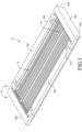
- the carrier 10 includes an outer frame 12, an upper support structure 14, and a lower support structure 16.
- the outer frame 12 comprises two spaced-apart side members 18a,b and two spaced-apart end members 20a,b.
- the first and second end members 20a,b may be coupled to and extend between opposite ends of first and second side members 18a,b to form outer frame 12.
- the frame may have a generally rectangular shape, as particularly shown in FIGS. 1 and 2 .
- first and second side members 18a,b include respective support projections 22a,b that are configured to engage respective first and second convey line support members, which are represented by dashed lines 24a and 24b in FIGS. 1 and 2 .
- the first and second support projections 22a,b of carrier 10 present first and second lower support surfaces 42a,b for supporting carrier 10 on first and second convey line support members 24a,b.
- Convey line support members 24a,b may be a moving convey line element such as, for example, a pair of chains (not shown) located on each side of carrier 10 as it moves through the microwave heating zone in a direction represented by the arrow in FIG. 4 .
- the first and second side members 18a,b and first and second end members 20a,b may be formed of any suitable material including, for example, a low loss material having a loss tangent of not more than about 10-4, not more than about 10 -3 , or not more than about 10 ⁇ 2 , measured at 20°C.
- a low loss material having a loss tangent of not more than about 10-4, not more than about 10 -3 , or not more than about 10 ⁇ 2 , measured at 20°C.
- Each of the side members 18a,b and end members 20a,b may be formed of the same material, at least one may be formed of a different material.
- suitable low loss tangent materials may include, but are not limited to, various polymers and ceramics.
- the low loss tangent material may be a food-grade material.
- the low loss material when it is a polymeric material, it may have a glass transition temperature of at least about 80°C, at least about 100°C, at least about 120°C, at least about 140°C, at least about 150°C, or at least about 160°C, in order to withstand the elevated temperatures to which the carrier may be exposed during heating of the articles.
- Suitable low loss polymers can include, for example, polytetrafluoroethylene (PTFE), polysulfone, polynorbornene, polycarbonate (PC), acrylonitrile butadiene styrene (ABS), poly(methyl methacrylate) (PMMA),polyetherimide (PEI), polystyrene, polyvinyl alcohol (PVA), polyvinyl chloride (PVC), and combinations thereof.
- the polymer can be monolithic or it may be reinforced with glass fibers, such as, for example glass-filed PTFE ("TEFLON"). Ceramics, such as aluminosilicates, may also be used as the low loss material.
- the carrier 10 may include an upper support structure 14 and a lower support structure 16 for holding a group of articles within the carrier, while also permitting microwave energy pass through the carrier 10 to the articles.
- the upper and lower support structures 14, 16 may each include a plurality of support members extending between the end members 20a,b in a direction substantially parallel to the side members 18a,b.
- the support members may extend in a direction substantially perpendicular to the end members 20a,b.
- the terms "substantially parallel” and “substantially perpendicular” mean within 5° of being parallel or perpendicular, respectively.
- upper and lower support structures 14, 16 could include a grid member or substantially rigid sheets of a microwave transparent or semi-transparent material extending between the side members 18a,b and end members 20a,b. Additional details regarding the number, dimensions, and configurations of support structures 14 and 16 are provided in U.S. Patent Application Publication No. 2017/0099704 .
- one or more of the support members may be formed of a strong, electrically conductive material.
- Suitable electrically conductive materials can have a conductivity of at least about 10 3 Siemens per meter (S/m), at least about 10 4 S/m, at least about 10 5 S/m, at least about 10 6 S/m, or at least about 10 7 S/m at 20°C, measured according to ASTM E1004 (09).
- the electrically conductive material may have a tensile strength of at least about 50 MegaPascals (MPa), at least about 100 MPa, at least about 200 MPa, at least about 400 MPa, or at least about 600 MPa, measured according to ASTM E8/E8M-16a, and/or it may also have a yield strength of at least about 50, at least about 100, at least about 200, at least about 300, or at least about 400 MPa at 20°C, measured according to ASTM E8/E8M-16a.
- MPa MegaPascals
- the Young's Modulus of the electrically conductive material can be at least about 25 GigaPascals (GPa), at least about 50 GPa, at least about 100 GPa, or at least about 150 GPa and/or not more than about 1000 GPa, not more than about 750 GPa, not more than about 500 GPa, or not more than about 250 GPa, measured at 20°C, measured according to ASTM E111-04 (2010).
- the electrically conductive material may be metallic and, in some cases, may be a metal alloy.
- the metal alloy may include any mixture of suitable metal elements including, but not limited to, iron, nickel, and/or chromium.
- the electrically conductive material may comprise stainless steel and may be food-grade stainless steel.
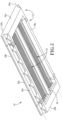
- carrier 10 defines a cargo volume 32 for receiving and holding a plurality of articles 40.
- Cargo volume 32 is at least partially defined between the upper and lower support structures 14 and 16, which are vertically spaced apart from one another, and the side 18a,b and end 20a,b members.
- the articles received in cargo volume 32 may be in contact with and/or held in position by at least a portion of the individual support members presentin the upper and lower support structures 14 and 16.
- Each of upper and lower support structures 14, 16 may be coupled to outer frame 12 in a removable or hinged manner so that at least one of the upper and lower support structures 14, 16 may be opened to load the articles 40 into carrier 10, closed to hold the articles 40 during heating, and opened again to unload the articles 40 from the carrier.
- Cargo volume 32 has a length (Lc) measured between opposing internal surfaces of the first and second end members 20a,b, as generally shown in FIG. 5 , a width (Wc) measured between opposing internal surfaces of the first and second side members 18a,b, as generally shown in FIG. 6 , and a height (He) measured between opposing internal surfaces of the upper and lower support structures 14, 16, as also generally shown in FIG. 6 .
- the length of the cargo volume 32 can be in the range of from about 0.1524 to about 3.048 meters (0.5 to about 10 feet), about 0.3048 to about 2.4384 meters (1 to about 8 feet), or about 0.6096 to about 1.8288 meters (2 to about 6 feet), and the width of the cargo volume can be in the range of from about 0.1524 to about 3.048 meters (0.5 to about 10 feet), about 0.3048 to about 2.4384 meters (1 to about 8 feet), or from about 0.6096 to about 1.8288 meters (2 to about 6 feet).
- the height of the cargo volume 32 may be in the range of from about 1.27 to about 20.32 centimeters (0.50 to about 8 inches), from about 1.905 to about 15.24 centimeters (0.75 to about 6 inches), from about 2.54 to about 10.16 centimeters (1 to about 4 inches), or from about 3.175 to about 5.08 centimeters (1.25 to about 2 inches).
- the cargo volume 32 can have a total volume in the range of from about 0.0566 to about 0.850 cubic meters (2 to about 30 cubic feet), about 0.1133 to about 0.5663 cubic meters (4 to about 20 cubic feet), about 0.1699 to about 0.4248 cubic meters (6 to about 15 cubic feet), or about 0.1841 to about 0.2832 cubic meters (6.5 to about 10 cubic feet).
- the carrier may further include at least one article spacing member for adjusting the size and/or shape of the cargo volume 32.
- article spacing members include dividers, shown in FIGS. 1 and 2 as divider 34, for dividing the cargo volume 32 into two or more compartments and vertical spacers, shown in FIG. 5 as spacers 38a,b, for adjusting the vertical height between the upper and lower support structures 14, 16.
- the article spacing member, or members may be permanently or removably coupled to the outer frame 12 or at least one of the upper and lower support structures 14, 16.
- an article spacing member When an article spacing member is removably coupled to the outer frame 12 and/or to the upper and lower support members 14, 16, it may be selectively inserted into and removed from the carrier 10 in order to change the size and/or shape of the cargo volume 32 so that the carrier 10 may hold many types of articles having different sizes and/or shapes.
- the carrier 10 When the article spacing member or members are permanently, or fixedly, coupled to the outer frame 12 and/or upper and lower support members 14, 16, the carrier 10 may be configured to carry a few, or only one, type of articles. Both types of carriers may be used according to the present invention.
- the carrier 10 includes one or more dividers 34 for dividing the cargo volume 32 into multiple compartments, as particularly shown in FIGS. 1 , 2 , and 6 , the compartments may extend in a direction substantially parallel to the first and second side members 18a,b. As a result, each compartment may be spaced apart from an adjacent compartment along the width of the carrier 10. Therefore, each compartment, examples of which are shown as compartments 36a-d in FIGS.
- the cargo volume 32 of carrier 10 may have a length and height similar to that of cargo volume 32 as described above, but may have a width that is in the range offrom 5 to 95 percent, 10 to 90 percent, 20 to 80 percent, 25 to 75 percent, or 40 to 60 percent of the entire width of the cargo volume 32, or it can be at least about 5, at least about 10, at least about 15, at least about 20, or at least about 25 percent and/or not more than about 95, not more than about 90, not more than about 85, not more than about 80, not more than about 75, not more thanabout 70, not more than about 60, not more than about 55, not more than about 50, not more thanabout 40, not more than about 35, not more than about 30, or not more than about 25 percent of the entire width of the cargo volume 32.
- the width of each individual compartment can be in therange of from 5.08 to 60.96 centimeters (2 to 24 inches), 10.16 to 45.72 centimeters (4 to 18 inches), or 12.7 to 25.4 centimeters (5 to 10 inches).
- a group of articles may be loaded into the cargo volume of the carrier and held therein while the carrier transports the articles through the microwave heating system.
- the articles processed may include packages of any suitable size and/or shape and may contain any food or beverage, any medical, dental, pharmaceutical or veterinary fluid, or any instrument capable of being processed in a microwave heating system.
- suitable foodstuffs can include, but are not limited to, fruits, vegetables, meats, pastas, pre-made meals, soups, stews, jams, and even beverages.
- the material used to form the package itself is not limited, but at least a portion of it must be at least partially microwave transparent in order to facilitate heating of the contents using microwave energy.
- Articles held in carriers and processed by microwave heating systems as described herein may have any suitable size and shape.
- each article, or more specifically its package can have a length of at least about 2.54 (1), at least about 5.08 (2), at least about 10.16 (4), or at least about 15.24 (6) centimeters (inches) and/or not more than about 45.72 (18), not more than about 30.48 (12), not more than about 25.4 (10), not more than about 20.32 (8), or not more than about 15.24 (6) centimeters (inches).
- each article may be in the range of from about 2.54 (1) to about 45.72 (18) centimeters (inches), about 5.08 (2) to about 30.48 (12) centimeters (inches), about 10.16 (4) to about 25.4 (10) centimeters (inches), or about 15.24 (6) to about 20.32 (8) centimeters (inches).
- the width of each article may be at least about 2.54 centimeters (1 inch), at least about 5.08 centimeters (2 inches),at least about 10.16 centimeters (4 inches), at least about 11.43 centimeters (4.5 inches), or at least 12.7 centimeters (5 inches) and/or not more than about 30.48 centimeters (12 inches), not more than about 25.4 centimeters (10 inches), not more than about 20.32 centimeters (8 inches), or not more than 15.24 centimeters (6 inches).
- the width of each article may be in the range of from about 2.54 centimeters (1 inch) to about 30.48 centimeters (12 inches), about 5.08 centimeters (2 inches) to about 25.4 centimeters (10 inches), about 10.16 centimeters (4 inches) to about 20.32 centimeters (8 inches), about 11.43 centimeters (4.5 inches) to about 15.24 centimeters (6 inches), orabout 12.7 centimeters (5 inches) to about 15.24 centimeters (6 inches).
- Each article may have a depth of at least about 1.27 centimeters (0.5 inches), at least about 2.54 centimeters (1 inch), at least about 3.81 centimeters (1.5 inches) and/or not more than about 20.32 centimeters (8 inches), not more than about 15.24 centimeters (6 inches), or not more than about 7.62 centimeters (3 inches), or a depth in the range of from about 1.27 (0.5) to about 20.32 centimeters (8 inches), about 5.08 (2) to about 15.24 centimeters (6 inches), or 3.81 to 7.62 centimeters (1.5 to 3 inches).
- the article can be square, such that its length and width are approximately the same.
- the article can have a total interior volume of at least about 313.48 (10.6), at least about 317.92 (10.75), at least about 322.35 (10.9), at least about 325.31 (11), at least about 354.88 (12) or at least about 443.60 (15) cubic centimeters (ounces), and/or not more than about 887.21 (30), not more than about 739.34 (25),or not more than about 591.47 (20) cubic centimeters (ounces).
- the terms "length” and “width” refer to the longest and second longest, respectively, non-diagonal dimensions of an article.
- the length and width of the article are measured at the largest cross-section (usually the top surface).
- the height of the article is the shortest non-diagonal dimension measured perpendicular to the plane defined by the length and width.
- the articles may be individually packaged items having a generally square, rectangular, or elliptical cross-sectional shape and may be formed of any suitable material including, but not limited to, various types of plastic, cellulosic materials, and other microwave-transparent materials.
- FIGS. 7a-d Various views of an exemplary trapezoidal-shaped article 250 having a rectangular cross-section are depicted in FIGS. 7a-d , below, with the length (L), width (W), and height (h) of the article being shown therein.
- the L:W of articles used as described herein can beat least 1.05:1, at least 1.1:1, or at least 1.15:1 and/or not more than about 1.38:1, not more than about 1.37:1, not more than about 1.36:1, not more than about 1.35:1, not more than about 1.34:1, not more than about 1.33:1, not more than about 1.32:1, not more than about 1.31:1, not more than about 1.30:1, not more than about 1.29:1, not more than about 1.28:1, not more than about 1.27:1, not more than about 1.26:1, not more than about 1.25:1, not more than about 1.24:1, not more than about 1.23:1, not more than about 1.22:1, not more than about 1.21:1, not more than about 1.20:1, not more than about 1.19:1, not more than about 1.18:1, not more than about 1.17:1, not more than about 1.16:1, not more than about 1.15:1, not more than about 1.14:1, not more than about 1.13:1, not more than about 1.12:1, not more than about
- the dimensions of the article may also be described relative to the size of the wavelength of the predominant mode of microwave energy introduced into the microwave chamber where the articles are heated, as measured in the fluid medium within the microwave chamber.
- the wavelength of the predominant mode of microwave energy introduced into the heating chamber is represented by lambda, ⁇ .
- the wavelength of the predominant mode of microwave energy can be at least about 3.683 (1.45), at least about 3.81 (1.50), at least about 3.94 ( 1.55), at least about 4.06 (1.60) centimeters inches and/or not more than about 4.57 (1.80), not more than about 4.45 ( 1.75), or not more than about 4.32 centimeters (1.70 inches).
- the articles can have a width that is at least at least 2.70 ⁇ , at least about 2.75 ⁇ , at least about 2.80 ⁇ , at least about 2.85 ⁇ , at least about 2.90 ⁇ , at least about 2.95 ⁇ , at least about 3.0 ⁇ and/or not more than about 3.5 ⁇ , not more than about 3.25 ⁇ , not more than about 3.2 ⁇ , not more than about 3.15 ⁇ , or not more than about 3.10 ⁇ . It should also be understood that the predominant wavelength ⁇ is determined at the conditions of operation of the microwave heating chamber.
- the articles When loaded into a carrier as described herein, the articles may be placed within the cargo volume defined between the upper and lower support structures of the carrier.
- the cargo volume may comprise a single compartment, or it may be divided into two or more smaller compartments using one or more dividers, as discussed previously. Overall, the cargo volume can be configured to hold at least 6, at least 8, at least 10, at least 16, at least 20, at least 24, at least 30, or at least 36 articles and/or not more than 100, not more than 80, not more than 60, not more than 50, not more than 40, or not more than 30 articles in total. Articles may be loaded into the carrier manually and/or with any suitable type of automated device.
- the carrier includes one or more dividers to separate the cargo volume into two or more individual compartments
- similar results have been observed when the ratio of the width of at least one of the articles to the width of at least one of the individual lanes is at least about 0.67:1, at least about 0.68:1, at least about 0.69:1, at least about 0.70:1, at least about 0.71:1, at least about 0.72:1, at least about 0.73:1, at least about 0.74:1, or at least about 0.75:1.
- this ratio may be not more than about 0.85:1, not more than about 0.82:1, not more than about 0.80:1, not more than about 0.77:1, or not more than about 0.76:1.
- FIG. 8 a top view of one example of a carrier 10 loaded with a plurality of articles 40 is provided.
- the articles 40 shown in FIG. 8 are arranged in single rows that extend along the length of the carrier.
- the articles may be arranged in at least 2, at least 3, at least 4, at least 5, at least 6, or at least 7 single rows and/or not more than 15, not more than 12, not more than 10, or not more than 8 single rows.
- the articles in carrier 10 are arranged in two or more rows, the articles in adjacent rows can be spaced apart from one another along the width of the carrier in a side-by-side configuration.
- the rows of articles may be spaced apart from one another via one or more dividers 34, while, in other embodiments, no divider may be used.
- there may be no gaps between consecutive articles in a single row so that the articles are in contact with one another when loaded into the carrier.
- at least a portion of consecutive articles in a single row may overlap horizontally.
- the specific arrangement of articles in the carrier may depend, at least in part, on the shape of the articles.
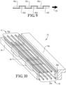
- the articles may have a general trapezoidal-like shape, such as the one described above with respect to FIGS. 7a through 7d , the articles may be arranged in a nested configuration, which is generally illustrated in FIGS. 8 and 9 .
- a row of articles 40a-f loaded into the carrier is sequentially oriented in the direction of travel 50 in a top down, top up, top down, top up configuration.
- the tops of the articles in carrier 10 are marked with a "T”
- the bottoms of the articles in carrier 10 are marked with a "B”
- the direction of travel is shown by arrow 50.
- a plurality of dividers 34 as discussed previously, are used to separate the individual rows of nested articles within the carrier 10. As particularly shown in FIG.
- the bottom of the second article 40b when arranged in a nested configuration, is oriented between the top of the first article 40a and the top of the third article 40c. Additionally, in a nested configuration, the tops of one set of alternating articles 40a, 40c, and 40e and the bottoms of the other set of alternating articles 40b, 40d, and 40f contact the upper support structure (not shown in FIGS. 8 and 9 ), while the bottoms of one set of alternating articles 40a, 40c, and 40e and the tops of the other set of alternating articles 40b, 40d, and 40f contact the lower support structure (now shown in FIGS. 8 and 9 ) when the articles are loaded into carrier 10. It has been discovered that arranging the articles in a nested configuration can provide for more uniform heating. In some cases, the articles arranged in a nested configuration can be rigid articles such as trays, containers, and the like.
- FIG. 10 Another view of articles arranged in a nested configuration is shown in FIG. 10 , below.
- the articles 40 are lined up in a single row in one compartment 36a of the cargo volume that is defined between upper and lower support structures 14, 16 and between divider 34 and side member 18a.
- FIG. 10 also illustrates one example of upper and lower support structures 14, 16 that respectively include upper and lower groups of support members, shown as 26a and 26b.
- the individual support members in upper and lower groups of support members 26a,b include slats having a generally rectangular cross sectional shape arranged so that the height of each slat is greater than its width.
- Such a configuration may provide superior strength and enhancement of microwave field uniformity, particularly when at least a portion of the slats are formed from an electrically conductive material.
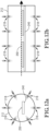
- FIGS. 11a and 11b schematic diagrams of the main steps of a microwave heating process and the main elements of a microwave heating system suitable for use according to embodiments of the present invention are provided.
- the articles which are loaded into one or more carriers (not shown), can initially be introduced into a thermalization zone 112, wherein the articles can be thermalized to a substantially uniform temperature.
- the articles can optionally be passed through a pressure adjustment zone 114a before being introduced into a microwave heating zone 116.
- microwave heating zone 116 the articles can be rapidly heated using microwave energy discharged into at least a portion of the microwave heating zone 116 by one or more microwave launchers 124, as generally shown in FIG. 11b .
- the heated articles can then optionally be passed through a holding zone 120, wherein the coldest portion of each article can be maintained at a temperature at or above a predetermined target temperature for a specified amount of time.
- the articles can then be passed from the microwave heating zone 116 (when no holding zone is present) or from the holding zone 120, when present, to a quench zone 122, wherein the temperature of the articles can be quickly reduced to a suitable handling temperature.
- the cooled articles can optionally be passed through a second pressure adjustment zone 114b before being removed from the system.
- the system may further cool the articles after the initial high-pressure cooling step in an atmospheric cooling chamber (not shown).
- the above-described thermalization 112, microwave heating 116, holding 120, and/or quench zones 122 of the microwave system depicted in FIGS. 11a and 11b can be defined within a single vessel, or at least one of the above-described stages or zones can be defined within one or more separate vessels. Additionally, in some cases, at least one of the above-described steps can be carried out in a vessel that is at least partially filled with a liquid medium in which the articles being processed can be at least partially submerged. As used herein, the term "at least partially filled” denotes a configuration where at least 50 percent of the volume of the specified vessel is filled with a liquid medium.
- the volume of at least one of the vessels used in the thermalization zone, the microwave heating zone, the holding zone, and the quench zone can be at least about 75 percent, at least about 90 percent, at least about 95 percent, or 100 percent filled with a liquid medium.
- the liquid medium used may be any suitable liquid medium.
- the liquid medium may have a dielectric constant greater than the dielectric constant of air and, in one embodiment, can have a dielectric constant similar to the dielectric constant of the articles being processed.
- Water or a liquid medium comprising water
- the liquid medium may also include one or more additives, such as, for example, oils, alcohols, glycols, and salts in order to alter or enhance its physical properties (e.g ., boiling point) at the conditions of operation.
- the microwave heating systems as described herein may include at least one conveyance system (not shown in FIGS. 11a and 11b ) for transporting the articles through one or more of the processing zones described above.
- suitable conveyance systems can include, but are not limited to, plastic or rubber belt conveyors, chain conveyors, roller conveyors, flexible or multi-flexing conveyors, wire mesh conveyors, bucket conveyors, pneumatic conveyors, screw conveyors, trough or vibrating conveyors, and combinations thereof. Any suitable number of individual convey lines can be used with the conveyance system, and the convey line or lines may be arranged in any suitable manner within the vessels.
- the loaded carriers introduced into the microwave system depicted in FIGS. 11a and 11b are initially introduced into a thermalization zone 112, wherein the articles are thermalized to achieve a substantially uniform temperature.
- a substantially uniform temperature For example, at least about 85 percent, at least about 90 percent, at least about 95 percent, at least about 97 percent, or at least about 99 percent of all the articles withdrawn from the thermalization zone 112 can have a temperature within about 5°C, within about 2°C, or within 1°C of one another.
- the terms "thermalize” and “thermalization” generally refer to a step of temperature equilibration or equalization.
- the heat transfer coefficient within the thermalization chamber can be increased, at least in part, by agitating the gaseous or liquid medium within the chamber using one or more agitation devices, such as, for example, one or more fluid jet agitators configured to turbulently discharge one or more fluid jets into the interior of the thermalization chamber.
- the fluid jets discharged into the thermalization chamber can be liquid or vapor jets and can have a Reynolds number of at least about 4500, at least about 8000, or at least about 10,000.
- fluid jet agitators 218 used in the thermalization chamber 212 can be any device configured to discharge a plurality of pressurized fluid jets toward the articles passing therethrough at one or multiple locations within thermalization chamber 212.
- fluid jet agitators 218 used in the thermalization chamber 212 can be any device configured to discharge a plurality of pressurized fluid jets toward the articles passing therethrough at one or multiple locations within thermalization chamber 212.
- FIG. 12a illustrates of one example of a thermalization chamber 212 including a plurality of fluid jet agitators 218.
- the fluid jet agitators 218 can be axially spaced from one another along the central axis of elongation of the thermalization chamber 212 (or the direction along which the articles are conveyed by a conveyor 240 shown by arrow 250) such that at least a portion of the pressurized jets are configured to discharge in a direction generally perpendicular to central axis of elongation (or direction of convey 250) of the articles.
- Such jets can be located on opposite sides of the thermalization chamber 212 and/or may also be circumferentially positioned within the thermalization chamber 212 such that at least a portion of the jets are directed radially inwardly toward the central axis of elongation (or convey direction 250) as generally shown in FIG. 12b .
- Similar configurations of fluidized jets may be employed in the microwave heating chamber and/or quench chamber, in addition to, or alternatively, to such jets in the thermalization chamber.
- the articles in the carrier passing through the thermalization zone 112 can be at least partially submerged in the liquid during the passing.
- the liquid medium in the thermalization zone 112 can be warmer or cooler than the temperature of the articles passing therethrough and, in some cases, can have an average bulk temperature of at least about 30°C, at least about 35°C, at least about 40°C, at least about 45°C, at least about 50°C, at least about 55°C, or at least about 60°C and/or not more than about 100°C, not more than about 95°C, not more than about 90°C, not more than about 85°C, not more than about 80°C, not more than about 75°C, not more than about 70°C, not more than about 65°C, or not more than about 60°C.
- the thermalization step can be carried out under ambient pressure or it may be carried out in a pressurized vessel.
- thermalization may be performed at a pressure of at least about 1, at least about 2, at least about 5, or at least about 10 psig and/or not more than about 80, not more than about 50, not more than about 40, or not more than about 25 psig.
- the thermalization zone 112 is liquid filled and pressurized, the pressure may be in addition to any head pressure exerted by the liquid.
- Articles undergoing thermalization can have an average residence time in the thermalization zone 112 of at least about 30 seconds, at least about 1 minute, at least about 2 minutes, at least about 4 minutes and/or not more than about 20 minutes, not more than about 15 minutes, or not more than about 10 minutes.
- the articles withdrawn from the thermalization zone 112 can have an average temperature of at least about 20°C, at least about 25°C, at least about 30°C, at least about 35°C and/or not more than about 70°C, not more than about 65°C, not more than about 60°C, or not more than about 55°C.
- the thermalization zone 112 and microwave heating zone 116 may operate at substantially different pressures, and the carrier withdrawn from the thermalization zone 112 may be passed through a pressure adjustment zone 114a before entering the microwave heating zone 116.
- the pressure adjustment zone 114a may be any zone or system configured to transition the carrier between an area of lower pressure and an area of higher pressure.
- the difference between the low and high pressure zones may vary depending on the system and can, for example, be at least about 1 psig, at least about 5 psig, at least about 10 psig, at least about 12 psig and/or not more than about 50 psig, not more than about 45 psig, not more than about 40 psig, or not more than about 35 psig.
- another pressure adjustment zone 114b may also be present to transition the carrier between the higher-pressure microwave heating zone 116 or hold zone 120 and the lower-pressure quench zone 122.
- the first pressure adjustment zone 114a can transition the carrier from a lower pressure thermalization zone 112 to a higher pressure microwave heating zone 116, while the second pressure adjustment zone 114a may transition the carrier from a higher pressure holding zone 120 (or portion of the quench zone 122) to a lower pressure quench zone 122 (or portion thereof).
- the loaded carrier may be introduced into the microwave heating zone 116, wherein the articles may be heated using at least a portion of the microwave energy discharged into a microwave heating chamber via one or more microwave launchers 124.
- microwave energy refers to electromagnetic energy having a frequency between 300 MHz and 30 GHz.
- Various configurations of microwave heating systems may employ microwave energy having a frequency of about 915 MHz or about 2450 MHz, with the former being preferred.
- the microwave heating zone 116 my optionally utilize one or more other types of heat sources such as, for example, various conductive or convective heating methods of devices.
- At least about 50, at least about 55, at least about 60, at least about 65, at least about 70, at least about 75, at least about 80, at least about 85, at least about 90, or at least about 95 percent of the energy used to heat the articles can be microwave energy from a microwave source.
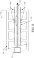
- the microwave heating zone shown in FIG. 13 generally includes a microwave heating chamber 330, at least one microwave generator 332 for generating microwave energy, and a microwave distribution system 334 for directing at least a portion of the microwave energy from the generator or generators 332 to the microwave heating chamber 330.
- the system further comprises one or more microwave launchers, shown as top and bottom groups of launchers 324a and 324b in FIG. 13 , for discharging microwave energy into the interior of the microwave heating chamber.
- the microwave heating zone may also include a convey system 340 having a convey line support for transport a plurality of carriers 312 loaded with groups of articles through the microwave heating zone 316.
- Each microwave launcher in a microwave heating zone may be configured to emit a particular amount of microwave energy into the microwave heating chamber.
- each microwave launcher may be configured to emit at least about 5, at least about 7, at least about 10, at least about 15 kW and/or not more than about 50, not more than about 40, not more than about 30, not more than about 25, not more than about 20, or not more than about 17 kW.
- each launcher may emit the same amount of energy as one or more other launchers, or at least one launcher may emit a different ( e.g ., lower or higher) amount of energy, as compared to at least one of the other launchers.
- the total amount of energy discharged into the microwave heating chamber can be at least about 25 kW, at least about 30 kW, at least about 35 kW, at least about 40 kW, at least about 45 kW, at least about 50 kW, at least about 55 kW, at least about 60 kW, at least about 65 kW, at least about 70 kW, or at least about 75 kW and/or not more than about 100 kW, not more than about 95 kW, not more than about 90 kW, not more than about 85 kW, not more than about 80 kW, not more than about 75 kW, not more than about 70 kW, or not more than about 65 kW.
- the microwave heating zone includes two or more microwave launchers
- at least some of the launchers may be positioned on the same side of the microwave heating chamber, such as, for example, launchers 324a shown in FIG. 13 .
- These same-side launchers may be axially spaced from one another along the length of the microwave heating chamber, in a direction parallel to the direction of travel of the carrier (or the convey direction) passing through the microwave heating chamber 330.
- the microwave heating zone 316 may also include two or more same-side launchers that are laterally spaced from one another in a direction generally perpendicular to the direction of travel of the carriers through the chamber.
- each same-side launcher 324 As the carrier moves along the convey line 340 through the microwave heating chamber 330, it passes by each same-side launcher 324. As the carrier passes near a launcher 324, at least a portion of the microwave energy emitted from the launcher 324 is directed toward the articles. Once the carrier has moved past one of the same-side launchers 324, there may be a "rest" or dwell time in which little, or no, microwave energy is directed toward the articles.
- the dwell time between launchers 324 in the microwave heating zone 316 can be at least about 0.5 seconds, at least about 0.75 seconds, at least about 1 second, at least about 2 seconds, or at least about 3 seconds and/or not more than about 10 seconds, not more than about 8 seconds, not more than about 6 seconds, not more than about 4 seconds, or not more than about 2 seconds.
- little (e.g., less than 5 kW) or no microwave energy may be discharged from one or more of the launchers, while the carrier remains stationary or moves through at least a portion of the microwave chamber 330.
- the total dwell time experienced by the articles in a single carrier can be at least about 3, at least about 5, at least about 6, at least about 10, at least about 15, or at least about 20 seconds and/or not more than about 5 minutes, not more than about 2 minutes, not more than about 1 minute, or not more than about 30 seconds.
- the convey line 340 may be configured so that the carrier moves back and forth through the microwave heating chamber 330.
- the total number of times a single carrier passes by a given microwave launcher 324 (or passes through a microwave energy field created by energy discharged by a launcher) as it moves through the microwave heating chamber 330 can be at least about 2, at least about 3, at least about 4, at least about 5, at least about 6, or at least about 7 times and/or not more than 12, not more than about 10, not more than about 9, not more than about 8, or not more than about 6 times.
- an amount of microwave energy within one or more of the above ranges may be discharged from at least one of the microwave launchers 324.
- the microwave heating zone 316 may also include at least two launchers positioned on opposite sides of the microwave chamber, such as, for example, launchers 324a and lower launchers 324b shown in FIG. 13 .
- These opposed, or oppositely disposed, launchers may be oppositely facing, such that launch openings of the launchers are substantially aligned, or staggered such that the launch openings of opposed launchers are axially and/or laterally spaced from each other.
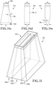
- a microwave launcher 822 comprises a set of broader opposing sidewalls 832a,b and a set of narrower opposing end walls 834a,b, which collectively define a substantially rectangular launch opening 838.
- the launch opening 838 can have a width (Wi) and a depth (Di) that are defined by the lower terminal edges of sidewalls 832a,b and end walls 834a,b, respectively.
- Views of one of sidewalls 832 and several examples of suitable end walls 834 are shown in FIG. 14b and FIGS. 14c-e , respectively.
- the depth (Di) of launch opening 838 is less than its width (Wi).
- the depth is typically oriented in a direction perpendicular to the direction of travel of the carriers moving through the microwave heating chamber.
- launch opening 838 may be elongated in the direction of travel of the carriers (or the direction of extension of the microwave chamber), so that the width of the launcher defined by the longer terminal edges of the sidewalls 832a,b are oriented parallel to the direction of travel (or the direction of extension), while the depth of the launcher defined by the shorter terminal edges of the end walls 834a,b are aligned substantially perpendicular to the direction of travel (or extension).
- At least one of the pair of sidewalls 832a,b and the pair of end walls 834a,b can be flared such that at least one dimension of the microwave launcher inlet 836 (width W 0 or depth D 0 ) is smaller than the corresponding outlet dimension (width Wi or depth Di), as respectively illustrated in FIGS. 14b and 14c .
- the side and/or end walls define respective width and depth flare angles, ⁇ w and ⁇ d , as shown in FIGS. 14b and 14c .
- the width and/or depth flare angles ⁇ w and/or ⁇ d can be at least about 2°, at least about 5°, at least about 10°, or at least about 15° and/or not more than about 45°, not more than about 30°, or not more than about 15°.
- the values for the width and depth flare angles ⁇ w and ⁇ d can be the same, or each of ⁇ w and ⁇ d may have a different value.
- the end walls 838a,b of the microwave launcher 822 may have a depth flare angle ⁇ d that is smaller than the width flare angle ⁇ w .
- the depth flare angle ⁇ d can be not more than about 0°, such that the inlet depth D 0 and the outlet dimension Di of microwave launcher 822 are substantially the same, as shown in FIG. 14d , or the depth flare angle ⁇ d may be less than 0°, such that Di is smaller than D 0 , as shown in FIG. 14e .
- the microwave launcher used to direct microwave energy toward the articles passing through the microwave heating zone may include a single microwave inlet and two or more launch openings.
- a microwave launcher shown as launcher 922
- FIGS. 15 and 16 are provided in FIGS. 15 and 16 , below.
- Microwave launcher 922 includes an inlet 936 and first, second, and third spaced-apart launch openings 938a-c, which are laterally spaced from one another. Although shown as including three openings, it should be understood that similar microwave launchers having only two or four or more launch openings may also be used.
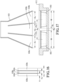
- the spacing between adjacent launch openings shown as dimensions x 1 and x 2 in FIG.
- 17 can be at least about 0.64 centimeters (0.25 inches), at least about 0.89 centimeters (0.35 inches), or at least about 1.14 centimeters (0.45 inches) and/or not more than about 2.54 centimeters (1 inch), not more than about 2.16 centimeters (0.85 inches), not more than about 2.03 centimeters (0.80 inches), not more than about 1.91 0.75, not more than about 1.78 centimeters (0.70 inches), or not more than about 1.65 centimeters (0.65 inches).
- the launch openings such as those shown in FIGS. 15-17 as launch openings 938a-c, may be spaced apart from one another by at least about 0.05 ⁇ ., at least about 0.075 ⁇ ., at least about 0.10 ⁇ . and/or not more than about 0.25 ⁇ , not more than about 0.20 ⁇ , or not more than about 0.15 ⁇ .
- the microwave launcher 922 may also include at least one dividing septum 940a,b disposed within the interior of the launcher and having a thickness at its terminal end equal to the desired spacing between the discharge openings 938a-c.
- the thickness of each septum may vary along its length, or longest dimension, between the inlet and outlet of the microwave launcher 922, as generally shown in FIG. 17 .
- each opening can define a depth, shown as d 1 through d 3 in FIGS. 15 and 16 .
- the depth of each launch opening 938a-c can be the same, or one or more may be different.
- the depth of each opening 938a-c can be, for example, at least about 3.81 (1.5), at least about 5.08 (2), at least about 6.35 (2.5), at least about 6.99 (2.75), at least about 7.62 (3), or at least about 8.26 centimeters (3.25 inches) and/or not more than about 12.7 (5), not more than about 11.43 (4.5), not more than about 10.16 (4), or not more than about 8.89 centimeters (3.5 inches).
- the launch openings 938a-c may have a depth of not more than about 0.625 ⁇ , not more than about 0.50 ⁇ , not more than about 0.45 ⁇ , not more than about 0.35 ⁇ , or not more than about 0.25 ⁇ .
- one or more of the launch openings 938a-c may have a depth greater than, less than, or equal to the depth of the microwave inlet 936. It should be understood that the depths of each launch opening938a-c does not include the thickness of the septa 940a,b, when present.
- the launch opening or openings defined by one or more microwave launchers may be at least partially covered by a substantially microwave-transparent window for fluidly isolating the microwave heating chamber from the microwave launcher.
- the microwave transparent windows when present, may prevent fluid flow between microwave chamber and the microwave launchers, while still permitting a substantial portion of the microwave energy from the launchers to pass therethrough and into the microwave chamber.
- the windows may be formed of any suitable material, including, but not limited to, one or more thermoplastic or glass material such as glass-filled Teflon, polytetrafluoroethylene (PTFE), poly(methyl methacrylate (PMMA), polyetherimide (PEI), aluminum oxide, glass, and combinations thereof.
- each window may be at least about 4 mm, at least about 6 mm, at least about 8 mm, or at least about 10 mm and/or not more than about 20 mm, notmore than about 16 mm, or not more than about 12 mm.
- Each window may be able to withstanda pressure difference of at least about 40 psig, at least about 50 psig, at least about 75 psi and/or not more than about 200 psig, not more than about 150 psig, or not more than about 120 psi without breaking, cracking, or otherwise failing.
- FIG. 17 a partial cross-sectional view of one configuration of a microwave launcher and an article-loaded carrier is shown.
- a carrier 912 loaded with articles 950 arranged in two side-by-side rows and positioned underneath a microwave launcher 922, which includes three microwave launch openings 938a-c.
- Such a configuration may occur when, for example, the carrier 912 is passing through a microwave heating chamber (not shown).
- the carrier 912 can include any suitable number of rows of articles, with the launcher 922 and carrier 912 having any suitable width in order to accommodate the articles, while still having dimensions and relative dimensions that fall within one or more of the ranges discussed herein.
- adjacent rows may be spaced apart from one another such that the distance between side-by-side articles in adjacent rows may be at least 1.27 centimeters (0.5 inches), at least about 2.54 centimeters (1 inch), at least about 3.81 (1.5), at least about 5.08 (2), at least about 6.35 (2.5), at least about 8.89 (3.5), at least about 11.43 (4.5), at least about 12.07 (4.75), at least about 12.19 (4.8), at least about 12.32 (4.85), or at least about 12.45 centimeters (4.9 inches) apart and/or not more than about 25.4 (10), not more than about 20.32 (8), not more than about 17.78 (7), not more than about 16.51 (6.5), not more than about 15.24 (6), not more than about 14.86 (5.85), not more than about 14.61 (5.75), or not more than about 14.22 centimeters (5.6 inches) apart, measured betweenthe geometric center points of adjacent articles, as shown as dimension D c in FIG.
- the spacing between adjacent edges of side-by-side articles can be at least about 0.64 centimeters (0.25 inches), at least about 0.76 centimeters (0.30 inches), at least about 1.14 centimeters (0.45) inches and/or not more than about 2.54 centimeters (1 inch), not more than about 1.91 centimeters (0.75 inches), or not more than about 1.40 centimeters (0.55 inches).
- the side-by-side articles in adjacent rows can be separated by at least one divider.
- no divider may be present.
- the divider may be in contact with the edges of the articles, such that the width of the divider falls within one or more of the ranges for spacing between adjacent edges of side-by-side articles described previously.
- the ratio of the distance between the center points of side- by-side articles 950 in adjacent rows in a carrier, shown as D c in FIG. 17 , to the width of the cargo volume of the carrier, shown as dimension W c in FIG. 17 may be at least 0.53:1, at least 0.54:1, at least about 0.55:1, at least about 0.56:1, or at least about 0.57:1. In some cases, this ratio may be not more than about 0.70:1, not more than about 0.65:1, not more than about 0.62:1, or not more than about 0.60:1.
- the distance between center points of side-by-side articles 950 in adjacent rows in the carrier 912 expressed in terms of the wavelength of the predominant mode of microwave energy introduced into the microwave chamber can be at least about 3.10 ⁇ , at least about 3.15 ⁇ , at least about 3.20 ⁇ , at least about 3.25 ⁇ , at least about 3.30 ⁇ , at least about 3.35 ⁇ , or at least about 3.40 ⁇ and/or not more than about 4.0 ⁇ , not more than about 3.75 ⁇ , not more than about 3.70 ⁇ , not more than about 3.65 ⁇ , or not more than about 3.60 ⁇ .
- articles having a width, shown as W in FIG. 18 that is at least about 1.25, at least about 1.27, at least about 1.30, at least about 1.32, at least about 1.35, at least about 1.37, at least about 1.40, or at least about 1.42 times the depth of each of the launch openings, shown as d 1 through d 3 in FIG. 17 , facilitate more uniform heating of the contents of the articles.
- W width
- the microwave launcher 922 has multiple launch openings 938a-c
- the ratios provided herein apply to each of the openings individually, whether the openings each have a depth that is the same as, or different than, the depths of one or more other launch openings.
- the ratio of the width (W) of each article 950 to the depth of each of the launch openings 938a-c, shown as d 1 through d 3 in FIGS. 16 and 17 can be not more than about 2:1, not more than about 1.95:1, not more than about 1.90:1, not more than about 1.85:1, not more than about 1.80:1, not more than about 1.75:1, or not more than about 1.70:1.
- the ratio of the width of the cargo volume of the carrier 912, shown as W c in FIG. 17 , to the depth of each of the launch openings 938a-c, shown as d 1 through d 3 in FIG. 17 can be at least about 2.75:1, at least about 2.80:1, at least about 2.85:1, at least about 2.90:1, at least about 2.95:1, at least about 3.0:1, at least about 3.05:1, at least about 3.10:1, at least about 3.15:1, at least about 3.20:1, at least about 3.25:1, at least about 3.30:1, at least about 3.35:1, at least about 3.40:1, at least about 3.45:1, or at least about 3.50:1.
- the ratio of the width of the cargo volume of the carrier to the depth of each of the launch openings 938a-c can be not more than about 4.2:1, not more than about 4.1:1, not more than about 4:1, not more than about 3.95:1, not more than about 3.9:1, not more than about 3.85:1, not more than about 3.8:1, not more than about 3.75:1, not more than about 3.7:1, not more than about 3.65:1, or not more than about 3.6:1.
- the ratio of the width of each individual compartment to the depth of each launch opening 938a-c, shown as d 1 through d 3 in FIG. 17 can be at least about 1.87:1, at least about 1.90:1, at least about 1.95:1, at least about 2.0:1, at least about 2.05:1, at least about 2.10:1, at least about 2.15:1, at least about 2.20:1, at least about 2.25:1, at least about 2.30:1, or at least about 2.32:1.
- the ratio of the width of each individual compartment to the depth of each launch opening 938a-c can be not more than about 2.80:1, not more than about 2.75:1, not more than about 2.70:1, not more than about 2.65:1, not more than about 2.6:1, not more than about 2.55:1, not more than about 2.5:1, not more than about 2.45:1, not more than about 2.4:1, not more than about 2.35:1.
- the microwave heating system is a sterilization or pasteurization system
- the target temperature can be a sterilization or pasteurization target temperature of at least about 65°C, at least about 70°C, at least about 75°C, at least about 80°C, at least about 85°C, at least about 90°C, at least about 95°C, at least about 100°C, at least about 105°C, at least about 110°C, at least about 115°C, at least about 120°C, at least about 121°C, at least about 122°C and/or not more than about 130°C, not more than about 128°C, not more than about 126°C, not more than about 125°C, not more than about 122°C, not more than about 120°C, not more than about 115°C, not more than about 110°C, not more than
- the microwave heating chamber in the microwave heating zone 116 may be at least partially liquid filled and at least a portion, or all, of the articles in the carrier may be submerged in the liquid medium during heating.
- the average bulk temperature of the liquid in the microwave heating chamber may vary and, in some cases, can depend on the amount of microwave energy discharged into the microwave heating chamber.
- the average bulk temperature of the liquid in the microwave heating chamber can be at least about 70°C, at least about 75°C, at least about 80°C, at least about 85°C, at least about 90°C, at least about 95°C, at least about 100°C, at least about 105°C, at least about 110°C, at least about 115°C, or at least about 120°C and/or not more than about 135°, not more than about 132°C, not more than about 130°C, not more than about 127°C, or not more than about 125°C.
- the liquid in the microwave heating chamber may be continually heated via one or more heat exchangers (not shown) and the temperature may remain generally constant such that, for example, it stays within about 2°C, within about 5°C, within about 7°C, or within less than 10°C of a predetermined set point.
- the liquid may not be heated or cooled by another source and its temperature may change by at least 10°C, at least about 12°, at least about 15°, at least about 20°C, or at least about 25°C during the microwave heating step.
- the articles may be heated to the target temperature in a relatively short period of time, which can help minimize any thermally-caused damage or degradation of the articles.
- the average residence time of each article passing through the microwave heating zone 116 can be at least about 5 seconds, at least about 20 seconds, at least about 60 seconds and/or not more than about 10 minutes, not more than about 8 minutes, not more than about 5 minutes, not more than about 3 minutes, not more than about 2 minutes, or not more than about 1 minute.
- the minimum temperature of the articles heated in the microwave heating zone 116 can increase by at least about 10°C, at least about 20°C, at least about 30°C, at least about 40°C, at least about 50°C, at least about 75°C and/or not more than about 150°C, not more than about 125°C, or not more than about 100°C, and the heating may be performed at a rate of at least about 5°C/min, at least about 10°C/min, at least about 15°C per minute (°C/min), at least about 25°C/min, at least about 35°C/min and/or not more than about 75°C/min, not more than about 50°C/min, not more than about 40°C/min, not more than about 30°C/min, or not more than about 20°C/min.
- the microwave heating chamber can be operated at approximately ambient pressure. Alternatively, it may be a pressurized microwave chamber that operates at a pressure that is at least 5 psig, at least about 10 psig, at least about 15 psig, or at least about 17 psig and/or not more than about 80 psig, not more than about 60 psig, not more than about 50 psig, or not more than about 40 psig above ambient pressure.
- ambient pressure refers to the pressure exerted by the fluid in the microwave heating chamber without the influence of external pressurization devices.
- the loaded carrier upon exiting the microwave heating zone, the loaded carrier may be passed to a holding zone, wherein the temperature of the articles can be maintained at or above a certain target temperature for a predetermined period of time.
- the temperature of the coldest part of the article can be held at a temperature at or above a predetermined minimum temperature of at least about 70°C, at least about 75°C, at least about 80°C, at least about 85°C, at least about 90°C, at least about 95°C, at least about 100°C, at least about 105°C, at least about 110°C, at least about 115°C, or at least about 120°C, at least about 121°C, at least about 122°C and/or not more than about 130°C, not more than about 128°C, or not more than about 126°C, for a period of time (or "hold period") of at least about 1 minute, at least about 2 minutes, or at least about 4 minutes and/or not more than about 20
- the carrier may be introduced into a quench zone 122, wherein the articles may be cooled as rapidly as possible via submersion in a cooled fluid.
- the quench zone 122 may be configured to reduce the external surface temperature of the articles by at least about 30°C, at least about 40°C, at least about 50°C and/or not more than about 100°C, not more than about 75°C, or not more than about 50°C in a time period of at least about 1 minute, at least about 2 minutes, at least about 3 minutes and/or not more than about 10 minutes, not more than about 8 minutes, or not more than about 6 minutes.
- any suitable fluid may be used in the quench zone 122 and, in some cases, the fluid may include a liquid similar to, or different than, the liquid used in the microwave heating zone 116 and/or the holding zone 120 (when present).
- the cooled articles can have a temperature of at least about 20°C, at least about 25°C, at least about 30°C and/or not more than about 70°C, not more than about 60°C, or not more than about 50°C.
- quench zone 122 can be pressurized, such that it is operated at a pressure of at least about 10, at least about 15, at least about 20, or at least about 25 psig and/or not more than about 100, not more than about 50, not more than about 40, or not more than about 30 psig above ambient pressure in the quench chamber.
- Such articles when removed from the heating system, include products that exhibit fewer hot and cold spots and have a uniform microbial lethality.
- an article heated as described herein may exhibit a smaller difference in temperature between its hottest and coldest portions as the article is removed from the holding zone 120 (when present) or from the microwave heating zone 116 (when no holding zone is present).
- the difference between the maximum temperature achieved by the hottest portion of each article withdrawn from the holding zone 120 (or the microwave heating zone 116) and the minimum temperature of the coldest portion of the same article is not more than 20°C, not more than about 17°C, not more than about 15°C, not more than about 12°C, not more than about 10°C, not more than about 8°C, or not more than about 5°C.
- the difference between the maximum temperature of all of the hottest portions of the articles in a single carrier withdrawn from the holding zone 120 (or microwave heating zone 116) and the minimum temperature of all of the coldest portions of the articles in the same carrier is not more than 30°C, not more than about 27°C, not more than about 25°C, not more than about 22°C, not more than about 20°C, not more than about 17°C, not more than about 15°C, not more than about 12°C, or not more than about 10°C.
- the former temperature difference indicates more uniform heating of each individual article, while the latter temperature difference is indicative of a more uniform heating of multiple articles within a carrier.
- the temperature of the hottest portion of the articles is not more than about 135°C, not more than about 133°C, not more than about 130°C, not more than about 127°C, or not more than about 125°C.
- the temperature of the coldest portion of each article may be at least about 119°C, at least about 120°C, at least about 121°C, at least about 123°C and/or not more than about 134°C, not more than about 133°C, not more than about 132°C, or not more than about 131°C.
- the temperature of the hottest portion of the articles may be at least about 75°C, at least about 80°C, or at least about 85°C and/or not more than about 120°C, not more than about 115°C, not more than about 110°C, not more than about 105°C, not more than about 100°C, or not more than about 95°C.
- articles removed from the holding zone 120 exhibit higher and/or a more consistent microbial lethality than articles processed by other systems.
- the coldest portions of each article can achieve a minimum microbial lethality (F 0 ) of Clostridium botulinum, measured at 250°F (121.1°C) with a z value of 18°F, of, of least about 1 minute, at least about 1.5 minutes, at least about 1.75 minutes, at least about 2 minutes, at least about 2.25 minutes, at least about 2.5 minutes, at least about 2.75 minutes, at least about 3 minutes, at least about 3.25 minutes, or at least about 3.5 minutes and/or not more than about 10 minutes, not more than about 8 minutes, not more than about 6 minutes, not more than about 4 minutes, not more than about 3.75 minutes, not more than about 3.5 minutes, not more than about 3.25 minutes, not more than about 3 minutes, not more than about 2.75 minutes, not more than about
- the coldest portion of each article can achieve a microbial lethality (F) of Salmonella or Escherichia coli (depending on the food being pasteurized), measured at 90°C with a z value of 6°C, of at least about 5 minutes, at least about 5.5 minutes, at least about 6 minutes, at least about 6.5 minutes, at least about 7 minutes, at least about 7.5 minutes, at least about 8 minutes, at least about 8.5 minutes, at least about 9 minutes, at least about 9.5 minutes, at least about 10 minutes, at least about 10.5 minutes, at least about 11 minutes, or at least about 11.5 minutes.
- the microbial lethality of Salmonella or E. coli can be not more than about 20 minutes, not more than about 19 minutes, not more than about 18 minutes, not more than about 17 minutes, or not more than about 16 minutes, measured according to ASTM F-1168-88(1994).
- the standard deviation (measured amongst several similar trials utilizing identical or nearly-identical articles) of the minimum F 0 value measured at the coldest portion of the coldest sterilized article may be not more than about 2.0, not more than about 1.75, not more than about 1.5, or not more than about 1.25 minutes. Additionally, the maximum microbial lethality, F 0max , measured at the hottest portion of the hottest sterilized article can be not more than 12 times, not more than about 10 times, or not more than about 8 times higher than the minimum F 0 for the same trial. microbial lethality. Similar deviations may be expected amongst several similar trials when the articles are pasteurized.
- Microwave heating systems can be commercial-scale heating systems capable of processing a large volume of articles in a relatively short time.
- microwave heating systems as described herein can be configured to achieve an overall production rate of at least about 10 packages per minute, at least about 15 packages per minute per convey line, at least about 20 packages per minute, at least about 25 packages per minute, or at least about 30 packages per minute per convey line, measured as described in the '516 Application.
- the terms “comprising,” “comprises,” and “comprise” are open-ended transition terms used to transition from a subject recited before the term to one or more elements recited after the term, where the element or elements listed after the transition term are not necessarily the only elements that make up the subject.
- the term "and/or,” when used in a list of two or more items, means that any one of the listed items can be employed by itself or any combination of two or more of the listed items can be employed. For example, if a composition is described as containing components A, B, and/or C, the composition can contain A alone; B alone; C alone; A and B in combination; A and C in combination; B and C in combination; or A, B, and C in combination.
- the microwave heating system included a thermalization zone, a microwave heating zone, a holding zone, and a cooling zone, which were all substantially filled with purified water.
- the microwave heating zone included a single pair of opposed microwave launchers each having three openings and configured in a similar manner as shown in FIGS. 15 and 16 .
- the width (longer dimension) of each launch opening was aligned parallel to the length of the carrier in the microwave heating zone.
- the depth of each of the outer openings shown as d1 and d3 in FIG.
- each of the two septa disposed within the launcher at least partially forming each of the openings had a width of 1.59 centimeters (0.625 inches).
- Containers formed from multi-layered polypropylene of different sizes and shapes were filled with either a combination of 30 weight percent egg white pasta noodles and 70 weight percent cheese sauce or a combination of 26 weight percent cheese tortellini and 74 weight percent red sauce.
- Table 1 Summary of Packaged Foodstuffs Package Type Container Contents Length, cm (in.) Width, cm(in.) Volume, cm 3 (oz.) Shape Noodle Sauce C-1 15.24 (6) 10.922 (4.3) 310.52 (10.5) Rectangular egg white pasta cheese sauce I-1 12.891 (5.075) 12.891 (5.075) 334.18 (11.3) Square egg white pasta cheese sauce I-2 12.891 (5.075) 12.891 (5.075) 334.18 (11.3) Square cheese tortellini red sauce I-3 17.107 (6.735) 12.891 (5.075) 334.18 (13.3) Rectangular cheese tortellini red sauce
- each carrier utilized metallic slats as part of the upper and lower groups of support members holding the articles within the cargo volume.
- the loaded carrier was introduced into the thermalization zone of the microwave heating system.
- the carrier was movedalong a convey line at an average speed of between 6.35 to 7.112 centimeters (2.5 to 2.8 inches) per second, and the averagebulk temperature of the water in the thermalization zone was between 65°C to 85°C.
- the total residence time of each loaded carrier in the thermalization zone was 35 minutes.
- the loaded carrier After being preheated in the thermalization zone, the loaded carrier was passed into the microwave heating zone. In some trials, the temperature of the liquid medium in the microwave heating zone remained generally constant at around 121°C, while in other trials, the temperature was permitted to fluctuate and generally ranged from about 95°C to about 125°C.
- the pressure of the microwave heating zone was 50 psig above the ambient pressure of the liquid medium.
- each carrier was subjected to a specific heating profile that included passing the carrier by the microwave launchers a total of four times and discharging a predetermined amount of microwave energy from the launcher during each pass. An effective dwell time of about 6 seconds was permitted between each passage.
- Tables 3a and 3b below.
- the articles After being heated, the articles remained submerged in a heated liquid having an average bulk temperature of between about 121°C to about 125°C for a hold time.
- the total holdtime ranged from 10 minutes to 15.5 minutes.
- the carrier was passed to apressurized quench zone, wherein the articles were cooled by contact with water having an average bulk temperature between 35°C and 40°C.
- the pressure of the cooling zone was 50 psig above the ambient pressure of the water.
- the articles were removed from the carrier and the microbial lethality (F 0 ) was measured for several articles in various locations.
- the microbial lethality of some articles was measured at the portion of the article that had achieved the highest temperature during the heating run, while the microbial lethality of other articles was measured at the portion of the article that had achieved the minimum temperature during the heating run.
- the F 0 value measured at the cold spots (min. F 0 ) provided information on the minimum microbial lethality exhibited by the articles in a given run, while the F 0 value measured at the hot spots (max. F 0 ) indicated the maximum lethality (which can indicate over processing) achieved by articles in the same run. Smaller ratios of maximum F 0 , determined at a hottest measured hot spot, to minimum F 0 , determined at the coldest measured cold spot, indicate a more uniform microbial lethality amongst all samples in a run.
- FIGS. 19a-c show the numbering and relative position for each package in each of the trials.
- the measured microbial lethality for each package provided in Table 5 below was measured at a cold spot of the package, except for the packages listed in Table 6.
- the microbial lethality for the packages numbered as shown in FIGS. 19a-c and listed in Table 6, were measured at a hot spot of the article.
- the ratios of maximum F 0 to minimum F 0 summarized in Table 5 was calculated as the ratio of the highest F 0 to the lowest F 0 measured for a given trial.
- Table 3a Summary of Heating Profiles Heating Profile # of Microwave Passes Energy Discharged per Pass, kW Total Energy Discharged (kW) Effective Dwell Time (s) 1 2 3 4 5 6 7 8 1 6 20 15 15 15 10 5 - - 80 6 2 6 10 10 10 5 5 - - 50 6 3 8 10 10 5 5 5 5 5 5 50 6 4 8 10 10 10 10 5 5 5 5 60 6 5 8 10 10 10 10 10 10 10 10 10 10 10 10 10 10 10 10 10 10 10 10 10 10 10 10 10 10 10 10 10 10 80 6
- Table 3b Summary of Water Temperature in Microwave Heating Zone Heating Profile Water Temperature per Pass, °C 1 2 3 4 5 6 7 8 1 121.1 121.1 121.1 121.1 121.1 121.1 121.1 - - 2 121.1 121.1 121.1 121.1 121.1 121.1 121.1 121.1 121.1 121.1 - - 3 95 105 110 115 118 121 123 125 4 95 105 110 115 118 121 123 125 5 95 105 110 115 118 121
Landscapes
- Physics & Mathematics (AREA)
- Electromagnetism (AREA)
- Food Preservation Except Freezing, Refrigeration, And Drying (AREA)
- Apparatus For Disinfection Or Sterilisation (AREA)
- Constitution Of High-Frequency Heating (AREA)
Description
- This application claims priority to
U.S. Patent Application No. 15/953,646, filed on April 16, 2018 U.S. Provisional Patent Application No. 62/486,040, filed on April 17, 2017 - The present invention relates to processes for heating articles using microwave energy. In particular, the present invention relates to methods for providing enhanced heating to packaged materials that are pasteurized or sterilized in large-scale microwave heating systems.
- Microwave radiation is a known mechanism for delivering energy to an object. The ability of microwave energy to penetrate and heat an object in a rapid and effective manner has proven advantageous in many chemical and industrial processes. Because of its ability to quickly and thoroughly heat an article, microwave energy has been employed in heating processes wherein the rapid achievement of a prescribed minimum temperature is desired, such as, for example, pasteurization or sterilization processes. Further, because microwave energy is generally non-invasive, microwave heating may be particularly useful for heating dielectrically sensitive materials, such as food and pharmaceuticals. However, to date, the complexities and nuances of safely and effectively applying microwave energy, especially on a commercial scale, have severely limited its application in several types of industrial processes. Furthermore, achieving efficient, yet uniform, heating of articles that achieves sufficient microbial lethality rates and minimizes thermal degradation of organoleptic properties of the material has proven challenging, particularly on a commercial scale.
- A need exists for a microwave heating system suitable for the sterilization or pasteurization of a wide variety of packaged foodstuffs and other items. The system would be capable of providing consistent, uniform, and rapid heating of the articles with a high degree of operational flexibility. Processes performed by such a system would minimize, or even prevent, hot and cold spots in the articles, and ensure the pasteurized and sterilized articles achieve target standards for microbial lethality and overall quality.
-
EP 2826338 A1 discloses a microwave heating system configured to heat a plurality of articles and a process for using the same. The heating system includes at least two laterally-spaced parallel convey lines and two or more groups of microwave launchers configured to heat articles transported along each convey line.WO 2017/059439 discloses carriers suitable for transporting a plurality of articles through a microwave heating zone. - The invention is defined in the appended claims.
- Various embodiments of the present invention are described in detail below with reference to the attached drawing Figures, wherein:
-
FIG. 1 is a top isometric view of a carrier suitable for use in one or more embodiments of the present invention; -
FIG. 2 is a bottom isometric view of the carrier shown inFIG. 1 ; -
FIG. 3 is an end view of the carrier shown inFIGS. 1 and2 ; -
FIG. 4 is a side view of the carrier shown inFIGS. 1-3 ; -
FIG. 5 is a longitudinal cross-section of the carrier shown inFIGS. 1-4 ; -
FIG. 6 is a transverse cross-section of the carrier shown inFIGS. 1-5 ; -
FIG. 7a is an isometric view of a package suitable for use in holding foodstuffs and other items to be heated according to embodiments of the present invention, particularly showing the length, width, and height dimensions of the package; -
FIG. 7b is a top view of the package shown inFIG. 7a ; -
FIG. 7c is a side view of the package shown inFIGS. 7a and 7b ; -
FIG. 7d is an end view of the package shown inFIGS. 7a-7c ; -
FIG. 8 is a is a top view of a plurality of articles arranged in a nested configuration within a carrier, particularly illustrating a divided row nested configuration; -
FIG. 9 is a side view of at least a portion of one row of articles arranged in a nested configuration; -
FIG. 10 is a partial isometric view of at least a portion of a row of articles arranged in a nested configuration in one compartment of a carrier defined between the side wall and a divider; -
FIG 11a is a schematic depiction of the major steps of a method for microwave pasteurizing or sterilizing a packaged foodstuff according to embodiments of the present invention; -
FIG. 11b is a schematic depiction of the major zones of a system for microwave pasteurizing or sterilizing a packaged foodstuff; -
FIG. 12a is schematic partial side cut-away view of a thermalization chamber suitable for use in a thermalization zone according to embodiments of the present invention, particularly showing locations of a plurality of fluid jet agitators; -
FIG. 12b is a schematic end view of the thermalization chamber shown inFIG. 12a ; -
FIG. 13 is a schematic partial side cut-away view of a microwave heating zone configured according to embodiments of the present invention, particularly illustrating one possible arrangement of the microwave heating vessel, the microwave launchers, and the microwave distribution system; -
FIG. 14a is an isometric view of a microwave launcher; -
FIG. 14b is a longitudinal side view of the microwave launcher depicted inFIG. 14a ; -
FIG. 14c is an end view of one embodiment of the microwave launcher generally depicted inFIGS. 14a and 14b , particularly illustrating a launcher having a flared outlet; -
FIG. 14d is an end view of another embodiment of the microwave launcher generally depicted inFIGS. 14a and 14b , particularly illustrating a launcher having an inlet and outlet of approximately the same depth; -
FIG. 14e is an end view of yet another embodiment of the microwave launcher generally depicted inFIGS. 14a and 14b , particularly illustrating a launcher having a tapered outlet; -
FIG. 15 is an isometric view of a microwave launcher having multiple launch openings; -
FIG. 16 is a bottom view of the launcher shown inFIG. 15 , particularly showing the orientation of the launch openings; -
FIG. 17 is a cross-sectional end view of a carrier loaded with a plurality of articles positioned near a microwave launcher particularly illustrating several relative dimensions of the carrier, the articles, and the launcher; -
FIG. 18 is a partial isometric view of a microwave launcher positioned near a carrier loaded with a plurality of articles configured and particularly illustrating some relative dimensions of the carrier, the articles, and the launch openings; -
FIG. 19a is a schematic diagram illustrating the location of several packaged food items heated in a microwave heating system in one of the heating trials described in the Example; -
FIG. 19b is a schematic diagram illustrating the location of several packaged food items heated in a microwave heating system in one of the heating trials described in the Example; and -
FIG. 19c is a schematic diagram illustrating the location of several packaged food items heated in a microwave heating system in one of the heating trials described in the Example. - The present invention relates to methods for the microwave-assisted pasteurization and sterilization of different types of articles. As used herein, the term "article" refers to the item being pasteurized or sterilized and the package in which it is enclosed. Although generally referred to herein as an "article," it should be understood that some of the properties or characteristics of the article described herein refer to the package itself (e.g., dimensions, shapes, materials of construction, etc.), while other properties or characteristics of the article described herein refer to the item within the package being pasteurized or sterilized (e.g., temperatures, microbial lethality rates, etc.) Examples of articles suitable for heating according to embodiments of the present invention include packaged foodstuffs, beverages, medical and pharmaceutical fluids, and medical and dental instruments. Unexpectedly, it has been found that articles utilizing packages having a larger width may result in more uniform heating of the package contents in a microwave heating system.
- The microwave heating system used for pasteurization or sterilization may include any suitable liquid-filled, continuous microwave heating system including, for example, those similar to the microwave heating systems described in U.S. Patent Application Publication No.
US2013/0240516 . Additionally, although described herein generally with reference to a foodstuff, it should be understood that embodiments of the present invention also relate to the pasteurization or sterilization of other types of items such as medical and dental instruments or medical and pharmaceutical fluids. - It has been unexpectedly found that packages having certain dimensions relative to the carrier and/or to certain components of the microwave heating system may be heated more uniformly than packages of other shapes and/or sizes. For example, it has been found that heating articles as described herein results in fewer hotspots and a more uniform degree of sterilization and/or pasteurization. Articles processed according to the present invention achieve the desired level of treatment in the same, or less, time. Consequently, the items being heated are not overheated or overcooked during processing, which results in a higher-quality end product with more desirable organoleptic properties, such as taste, texture, and color, and/or retained functionality.
- In general, pasteurization involves the rapid heating of a material to a minimum temperature between 80°C and 100°C, while sterilization involves heating the material to a minimum temperature between about 100°C and about 140°C. Systems and processes described herein may apply to pasteurization, sterilization, or both pasteurization and sterilization. In some cases, pasteurization and sterilization may take place simultaneously, or nearly simultaneously, sothat the articles being processed are both pasteurized and sterilized by the heating system. In some cases, pasteurization may be performed at lower temperatures and/or pressures and without a separate thermal equilibration period after the microwave-assisted heating, while sterilization may be performed at higher temperatures and/or pressures and can include a holding or thermal equilibration stage after the microwave-assisted heating step. In some embodiments, a single microwave system can be operationally flexible so that it is able to be selectively configured to pasteurize or sterilize various articles during different heating runs.
- Articles heated in a microwave heating system as described herein may initially be secured in a carrier configured to transport the articles through the system. Several views of an exemplary carrier are provided in
FIGS. 1 through 6 . As generally shown below, thecarrier 10 includes anouter frame 12, anupper support structure 14, and alower support structure 16. Theouter frame 12 comprises two spaced-apartside members 18a,b and two spaced-apart end members 20a,b. The first andsecond end members 20a,b may be coupled to and extend between opposite ends of first andsecond side members 18a,b to formouter frame 12. Whenside members 18a,b are longer than theend members 20a,b, the frame may have a generally rectangular shape, as particularly shown inFIGS. 1 and2 . - As shown in
FIGS. 1-4 , first andsecond side members 18a,b includerespective support projections 22a,b that are configured to engage respective first and second convey line support members, which are represented by dashedlines FIGS. 1 and2 . The first andsecond support projections 22a,b ofcarrier 10 present first and secondlower support surfaces 42a,b for supportingcarrier 10 on first and second conveyline support members 24a,b. Conveyline support members 24a,b may be a moving convey line element such as, for example, a pair of chains (not shown) located on each side ofcarrier 10 as it moves through the microwave heating zone in a direction represented by the arrow inFIG. 4 . - The first and
second side members 18a,b and first andsecond end members 20a,b may be formed of any suitable material including, for example, a low loss material having a loss tangent of not more than about 10-4, not more than about 10-3, or not more than about 10·2, measured at 20°C. Each of theside members 18a,b andend members 20a,b may be formed of the same material, at least one may be formed of a different material. Examples of suitable low loss tangent materials may include, but are not limited to, various polymers and ceramics. In some embodiments, the low loss tangent material may be a food-grade material. - When the low loss material is a polymeric material, it may have a glass transition temperature of at least about 80°C, at least about 100°C, at least about 120°C, at least about 140°C, at least about 150°C, or at least about 160°C, in order to withstand the elevated temperatures to which the carrier may be exposed during heating of the articles. Suitable low loss polymers can include, for example, polytetrafluoroethylene (PTFE), polysulfone, polynorbornene, polycarbonate (PC), acrylonitrile butadiene styrene (ABS), poly(methyl methacrylate) (PMMA),polyetherimide (PEI), polystyrene, polyvinyl alcohol (PVA), polyvinyl chloride (PVC), and combinations thereof. The polymer can be monolithic or it may be reinforced with glass fibers, such as, for example glass-filed PTFE ("TEFLON"). Ceramics, such as aluminosilicates, may also be used as the low loss material.
- As shown in
FIGS. 1 and2 , thecarrier 10 may include anupper support structure 14 and alower support structure 16 for holding a group of articles within the carrier, while also permitting microwave energy pass through thecarrier 10 to the articles. In the example shown inFIGS. 1 and2 , the upper andlower support structures end members 20a,b in a direction substantially parallel to theside members 18a,b. The support members may extend in a direction substantially perpendicular to theend members 20a,b. As used herein, the terms "substantially parallel" and "substantially perpendicular" mean within 5° of being parallel or perpendicular, respectively. In other instances (not shown), upper andlower support structures side members 18a,b andend members 20a,b. Additional details regarding the number, dimensions, and configurations ofsupport structures U.S. Patent Application Publication No. 2017/0099704 . - When the upper and/or
lower support structures FIGS. 1 and2 , above, one or more of the support members may be formed of a strong, electrically conductive material. Suitable electrically conductive materials can have a conductivity of at least about 103 Siemens per meter (S/m), at least about 104 S/m, at least about 105 S/m, at least about 106 S/m, or at least about 107 S/m at 20°C, measured according to ASTM E1004 (09). Additionally, the electrically conductive material may have a tensile strength of at least about 50 MegaPascals (MPa), at least about 100 MPa, at least about 200 MPa, at least about 400 MPa, or at least about 600 MPa, measured according to ASTM E8/E8M-16a, and/or it may also have a yield strength of at least about 50, at least about 100, at least about 200, at least about 300, or at least about 400 MPa at 20°C, measured according to ASTM E8/E8M-16a. - The Young's Modulus of the electrically conductive material can be at least about 25 GigaPascals (GPa), at least about 50 GPa, at least about 100 GPa, or at least about 150 GPa and/or not more than about 1000 GPa, not more than about 750 GPa, not more than about 500 GPa, or not more than about 250 GPa, measured at 20°C, measured according to ASTM E111-04 (2010). The electrically conductive material may be metallic and, in some cases, may be a metal alloy. The metal alloy may include any mixture of suitable metal elements including, but not limited to, iron, nickel, and/or chromium. The electrically conductive material may comprise stainless steel and may be food-grade stainless steel.
- As particularly shown in
FIG. 5 ,carrier 10 defines acargo volume 32 for receiving and holding a plurality ofarticles 40.Cargo volume 32 is at least partially defined between the upper andlower support structures side 18a,b andend 20a,b members. The articles received incargo volume 32 may be in contact with and/or held in position by at least a portion of the individual support members presentin the upper andlower support structures lower support structures outer frame 12 in a removable or hinged manner so that at least one of the upper andlower support structures articles 40 intocarrier 10, closed to hold thearticles 40 during heating, and opened again to unload thearticles 40 from the carrier. -
Cargo volume 32 has a length (Lc) measured between opposing internal surfaces of the first andsecond end members 20a,b, as generally shown inFIG. 5 , a width (Wc) measured between opposing internal surfaces of the first andsecond side members 18a,b, as generally shown inFIG. 6 , and a height (He) measured between opposing internal surfaces of the upper andlower support structures FIG. 6 . The length of thecargo volume 32 can be in the range of from about 0.1524 to about 3.048 meters (0.5 to about 10 feet), about 0.3048 to about 2.4384 meters (1 to about 8 feet), or about 0.6096 to about 1.8288 meters (2 to about 6 feet), and the width of the cargo volume can be in the range of from about 0.1524 to about 3.048 meters (0.5 to about 10 feet), about 0.3048 to about 2.4384 meters (1 to about 8 feet), or from about 0.6096 to about 1.8288 meters (2 to about 6 feet). The height of thecargo volume 32 may be in the range of from about 1.27 to about 20.32 centimeters (0.50 to about 8 inches), from about 1.905 to about 15.24 centimeters (0.75 to about 6 inches), from about 2.54 to about 10.16 centimeters (1 to about 4 inches), or from about 3.175 to about 5.08 centimeters (1.25 to about 2 inches). Overall, thecargo volume 32 can have a total volume in the range of from about 0.0566 to about 0.850 cubic meters (2 to about 30 cubic feet), about 0.1133 to about 0.5663 cubic meters (4 to about 20 cubic feet), about 0.1699 to about 0.4248 cubic meters (6 to about 15 cubic feet), or about 0.1841 to about 0.2832 cubic meters (6.5 to about 10 cubic feet). - Additionally, the carrier may further include at least one article spacing member for adjusting the size and/or shape of the
cargo volume 32. Examples of article spacing members include dividers, shown inFIGS. 1 and2 asdivider 34, for dividing thecargo volume 32 into two or more compartments and vertical spacers, shown inFIG. 5 asspacers 38a,b, for adjusting the vertical height between the upper andlower support structures outer frame 12 or at least one of the upper andlower support structures outer frame 12 and/or to the upper andlower support members carrier 10 in order to change the size and/or shape of thecargo volume 32 so that thecarrier 10 may hold many types of articles having different sizes and/or shapes. When the article spacing member or members are permanently, or fixedly, coupled to theouter frame 12 and/or upper andlower support members carrier 10 may be configured to carry a few, or only one, type of articles. Both types of carriers may be used according to the present invention. - When the
carrier 10 includes one ormore dividers 34 for dividing thecargo volume 32 into multiple compartments, as particularly shown inFIGS. 1 ,2 , and6 , the compartments may extend in a direction substantially parallel to the first andsecond side members 18a,b. As a result, each compartment may be spaced apart from an adjacent compartment along the width of thecarrier 10. Therefore, each compartment, examples of which are shown ascompartments 36a-d inFIGS. 5 and 6 , defined within thecargo volume 32 ofcarrier 10 may have a length and height similar to that ofcargo volume 32 as described above, but may have a width that is in therange offrom 5 to 95 percent, 10 to 90 percent, 20 to 80 percent, 25 to 75 percent, or 40 to 60 percent of the entire width of thecargo volume 32, or it can be at least about 5, at least about 10, at least about 15, at least about 20, or at least about 25 percent and/or not more than about 95, not more than about 90, not more than about 85, not more than about 80, not more than about 75, not more thanabout 70, not more than about 60, not more than about 55, not more than about 50, not more thanabout 40, not more than about 35, not more than about 30, or not more than about 25 percent of the entire width of thecargo volume 32. The width of each individual compartment can be in therange of from 5.08 to 60.96 centimeters (2 to 24 inches), 10.16 to 45.72 centimeters (4 to 18 inches), or 12.7 to 25.4 centimeters (5 to 10 inches). - According to the present invention, a group of articles may be loaded into the cargo volume of the carrier and held therein while the carrier transports the articles through the microwave heating system. The articles processed may include packages of any suitable size and/or shape and may contain any food or beverage, any medical, dental, pharmaceutical or veterinary fluid, or any instrument capable of being processed in a microwave heating system. Examples of suitable foodstuffs can include, but are not limited to, fruits, vegetables, meats, pastas, pre-made meals, soups, stews, jams, and even beverages. Additionally, the material used to form the package itself is not limited, but at least a portion of it must be at least partially microwave transparent in order to facilitate heating of the contents using microwave energy.
- Articles held in carriers and processed by microwave heating systems as described herein may have any suitable size and shape. For example, each article, or more specifically its package, can have a length of at least about 2.54 (1), at least about 5.08 (2), at least about 10.16 (4), or at least about 15.24 (6) centimeters (inches) and/or not more than about 45.72 (18), not more than about 30.48 (12), not more than about 25.4 (10), not more than about 20.32 (8), or not more than about 15.24 (6) centimeters (inches). The length of each article may be in the range of from about 2.54 (1) to about 45.72 (18) centimeters (inches), about 5.08 (2) to about 30.48 (12) centimeters (inches), about 10.16 (4) to about 25.4 (10) centimeters (inches), or about 15.24 (6) to about 20.32 (8) centimeters (inches). The width of each article may be at least about 2.54 centimeters (1 inch), at least about 5.08 centimeters (2 inches),at least about 10.16 centimeters (4 inches), at least about 11.43 centimeters (4.5 inches), or at least 12.7 centimeters (5 inches) and/or not more than about 30.48 centimeters (12 inches), not more than about 25.4 centimeters (10 inches), not more than about 20.32 centimeters (8 inches), or not more than 15.24 centimeters (6 inches). The width of each article may be in the range of from about 2.54 centimeters (1 inch) to about 30.48 centimeters (12 inches), about 5.08 centimeters (2 inches) to about 25.4 centimeters (10 inches), about 10.16 centimeters (4 inches) to about 20.32 centimeters (8 inches), about 11.43 centimeters (4.5 inches) to about 15.24 centimeters (6 inches), orabout 12.7 centimeters (5 inches) to about 15.24 centimeters (6 inches). Each article may have a depth of at least about 1.27 centimeters (0.5 inches), at least about 2.54 centimeters (1 inch), at least about 3.81 centimeters (1.5 inches) and/or not more than about 20.32 centimeters (8 inches), not more than about 15.24 centimeters (6 inches), or not more than about 7.62 centimeters (3 inches), or a depth in the range of from about 1.27 (0.5) to about 20.32 centimeters (8 inches), about 5.08 (2) to about 15.24 centimeters (6 inches), or 3.81 to 7.62 centimeters (1.5 to 3 inches). In some embodiments, the article can be square, such that its length and width are approximately the same. The article can have a total interior volume of at least about 313.48 (10.6), at least about 317.92 (10.75), at least about 322.35 (10.9), at least about 325.31 (11), at least about 354.88 (12) or at least about 443.60 (15) cubic centimeters (ounces), and/or not more than about 887.21 (30), not more than about 739.34 (25),or not more than about 591.47 (20) cubic centimeters (ounces).
- As used herein, the terms "length" and "width" refer to the longest and second longest, respectively, non-diagonal dimensions of an article. When the article has a generally trapezoidal shape such that the top of the article is longer and wider than its bottom, the length and width of the article are measured at the largest cross-section (usually the top surface). The height of the article is the shortest non-diagonal dimension measured perpendicular to the plane defined by the length and width. The articles may be individually packaged items having a generally square, rectangular, or elliptical cross-sectional shape and may be formed of any suitable material including, but not limited to, various types of plastic, cellulosic materials, and other microwave-transparent materials. Various views of an exemplary trapezoidal-shaped
article 250 having a rectangular cross-section are depicted inFIGS. 7a-d , below, with the length (L), width (W), and height (h) of the article being shown therein. - It has been found that the ratio of the length of an article to its width may have an impact on how uniformly its contents are heated when processed in a microwave heating system as described herein. Although not wishing to be bound by theory, it is hypothesized that utilizing articles having a slightly larger width than conventionally-sized articles may result in better heating of the article contents, including more uniform microbial lethality and fewer hot and cold spots. According to the invention, articles with a length to width ratio (L:W) of at least 1.01:1, or 1:1, and not more than 1.39:1 provide unexpected results. The L:W of articles used as described herein can beat least 1.05:1, at least 1.1:1, or at least 1.15:1 and/or not more than about 1.38:1, not more than about 1.37:1, not more than about 1.36:1, not more than about 1.35:1, not more than about 1.34:1, not more than about 1.33:1, not more than about 1.32:1, not more than about 1.31:1, not more than about 1.30:1, not more than about 1.29:1, not more than about 1.28:1, not more than about 1.27:1, not more than about 1.26:1, not more than about 1.25:1, not more than about 1.24:1, not more than about 1.23:1, not more than about 1.22:1, not more than about 1.21:1, not more than about 1.20:1, not more than about 1.19:1, not more than about 1.18:1, not more than about 1.17:1, not more than about 1.16:1, not more than about 1.15:1, not more than about 1.14:1, not more than about 1.13:1, not more than about 1.12:1, not more than about 1.11:1, not more than about 1.10:1, not more than about 1.09:1, not more than about 1.08:1, not more than about 1.07:1, not more than about 1.06:1, not more than about 1.05:1, not more than about 1.04:1, or not more than about 1.03:1.
- The dimensions of the article may also be described relative to the size of the wavelength of the predominant mode of microwave energy introduced into the microwave chamber where the articles are heated, as measured in the fluid medium within the microwave chamber. The wavelength of the predominant mode of microwave energy introduced into the heating chamber is represented by lambda, λ. In some cases, the wavelength of the predominant mode of microwave energy can be at least about 3.683 (1.45), at least about 3.81 (1.50), at least about 3.94 ( 1.55), at least about 4.06 (1.60) centimeters inches and/or not more than about 4.57 (1.80), not more than about 4.45 ( 1.75), or not more than about 4.32 centimeters (1.70 inches). The articles can have a width that is at least at least 2.70 λ, at least about 2.75 λ, at least about 2.80 λ, at least about 2.85 λ, at least about 2.90 λ, at least about 2.95 λ, at least about 3.0 λ and/or not more than about 3.5 λ, not more than about 3.25 λ, not more than about 3.2 λ, not more than about 3.15 λ, or not more than about 3.10 λ. It should also be understood that the predominant wavelength λ is determined at the conditions of operation of the microwave heating chamber.
- When loaded into a carrier as described herein, the articles may be placed within the cargo volume defined between the upper and lower support structures of the carrier. The cargo volume may comprise a single compartment, or it may be divided into two or more smaller compartments using one or more dividers, as discussed previously. Overall, the cargo volume can be configured to hold at least 6, at least 8, at least 10, at least 16, at least 20, at least 24, at least 30, or at least 36 articles and/or not more than 100, not more than 80, not more than 60, not more than 50, not more than 40, or not more than 30 articles in total. Articles may be loaded into the carrier manually and/or with any suitable type of automated device.
- As discussed previously, it has been discovered that utilizing wider articles provides unexpected benefits in terms of more uniform heating and a more consistent microbial lethality. It has also been discovered that employing carrier with a wider cargo volume may further enhance these benefits. For example, in some cases, enhanced results have been observed when the ratio of the width of at least one of the articles to the total width of the cargo volume into which the articles are placed is at least about 0.46:1, at least about 0.47:1, at least about 0.48:1, at least about 0.49:1, or at least about 0.50:1 and/or not more than about 0.55:1, not more than about 0.53:1, or not more than about 0.52:1. When the carrier includes one or more dividers to separate the cargo volume into two or more individual compartments, similar results have been observed when the ratio of the width of at least one of the articles to the width of at least one of the individual lanes is at least about 0.67:1, at least about 0.68:1, at least about 0.69:1, at least about 0.70:1, at least about 0.71:1, at least about 0.72:1, at least about 0.73:1, at least about 0.74:1, or at least about 0.75:1. In some cases, this ratio may be not more than about 0.85:1, not more than about 0.82:1, not more than about 0.80:1, not more than about 0.77:1, or not more than about 0.76:1.
- Turning now to
FIG. 8 , a top view of one example of acarrier 10 loaded with a plurality ofarticles 40 is provided. Thearticles 40 shown inFIG. 8 are arranged in single rows that extend along the length of the carrier. The articles may be arranged in at least 2, at least 3, at least 4, at least 5, at least 6, or at least 7 single rows and/or not more than 15, not more than 12, not more than 10, or not more than 8 single rows. When the articles incarrier 10 are arranged in two or more rows, the articles in adjacent rows can be spaced apart from one another along the width of the carrier in a side-by-side configuration. In some embodiments, the rows of articles may be spaced apart from one another via one ormore dividers 34, while, in other embodiments, no divider may be used. In some cases, it may be desirable to minimize the spacing between articles in a single row such that the average distance between consecutive edges of articles loaded into the carrier can be not more than about 2.54 centimeters (1 inch), not more than about 1.91 centimeter (0.75 inches), not more than about 1.27 centimeters (0.5 inches), not more than about 0.64 centimeters (0.25 inches), or not more than about 0.254 centimeters (0.1 inch). In some cases, there may be no gaps between consecutive articles in a single row so that the articles are in contact with one another when loaded into the carrier. In some cases, at least a portion of consecutive articles in a single row may overlap horizontally. - The specific arrangement of articles in the carrier may depend, at least in part, on the shape of the articles. When the articles have a general trapezoidal-like shape, such as the one described above with respect to
FIGS. 7a through 7d , the articles may be arranged in a nested configuration, which is generally illustrated inFIGS. 8 and9 . - In a nested configuration, adjacent articles in a single row, shown as 40a-f in
FIG. 9 , have opposite orientations. In the nested configuration, a row ofarticles 40a-f loaded into the carrier is sequentially oriented in the direction oftravel 50 in a top down, top up, top down, top up configuration. As shown inFIG. 8 , the tops of the articles incarrier 10 are marked with a "T", and the bottoms of the articles incarrier 10 are marked with a "B", and the direction of travel is shown byarrow 50. In the example shown inFIG. 8 , a plurality ofdividers 34, as discussed previously, are used to separate the individual rows of nested articles within thecarrier 10. As particularly shown inFIG. 9 , when arranged in a nested configuration, the bottom of thesecond article 40b is oriented between the top of thefirst article 40a and the top of thethird article 40c. Additionally, in a nested configuration, the tops of one set of alternatingarticles articles FIGS. 8 and9 ), while the bottoms of one set of alternatingarticles articles FIGS. 8 and9 ) when the articles are loaded intocarrier 10. It has been discovered that arranging the articles in a nested configuration can provide for more uniform heating. In some cases, the articles arranged in a nested configuration can be rigid articles such as trays, containers, and the like. - Another view of articles arranged in a nested configuration is shown in
FIG. 10 , below. As shown inFIG. 10 , thearticles 40 are lined up in a single row in onecompartment 36a of the cargo volume that is defined between upper andlower support structures divider 34 andside member 18a.FIG. 10 also illustrates one example of upper andlower support structures FIG. 10 , the individual support members in upper and lower groups ofsupport members 26a,b include slats having a generally rectangular cross sectional shape arranged so that the height of each slat is greater than its width. Such a configuration may provide superior strength and enhancement of microwave field uniformity, particularly when at least a portion of the slats are formed from an electrically conductive material. - Turning now to
FIGS. 11a and 11b , schematic diagrams of the main steps of a microwave heating process and the main elements of a microwave heating system suitable for use according to embodiments of the present invention are provided. - As shown in
FIGS. 11a and 11b , the articles, which are loaded into one or more carriers (not shown), can initially be introduced into athermalization zone 112, wherein the articles can be thermalized to a substantially uniform temperature. Once thermalized, the articles can optionally be passed through apressure adjustment zone 114a before being introduced into amicrowave heating zone 116. Inmicrowave heating zone 116, the articles can be rapidly heated using microwave energy discharged into at least a portion of themicrowave heating zone 116 by one ormore microwave launchers 124, as generally shown inFIG. 11b . The heated articles can then optionally be passed through a holdingzone 120, wherein the coldest portion of each article can be maintained at a temperature at or above a predetermined target temperature for a specified amount of time. Subsequently, the articles can then be passed from the microwave heating zone 116 (when no holding zone is present) or from the holdingzone 120, when present, to a quenchzone 122, wherein the temperature of the articles can be quickly reduced to a suitable handling temperature. After a portion (or all) of the cooling step, the cooled articles can optionally be passed through a secondpressure adjustment zone 114b before being removed from the system. In some cases, the system may further cool the articles after the initial high-pressure cooling step in an atmospheric cooling chamber (not shown). - The above-described
thermalization 112,microwave heating 116, holding 120, and/or quenchzones 122 of the microwave system depicted inFIGS. 11a and 11b can be defined within a single vessel, or at least one of the above-described stages or zones can be defined within one or more separate vessels. Additionally, in some cases, at least one of the above-described steps can be carried out in a vessel that is at least partially filled with a liquid medium in which the articles being processed can be at least partially submerged. As used herein, the term "at least partially filled" denotes a configuration where at least 50 percent of the volume of the specified vessel is filled with a liquid medium. In certain embodiments, the volume of at least one of the vessels used in the thermalization zone, the microwave heating zone, the holding zone, and the quench zone can be at least about 75 percent, at least about 90 percent, at least about 95 percent, or 100 percent filled with a liquid medium. - The liquid medium used may be any suitable liquid medium. For example, the liquid medium may have a dielectric constant greater than the dielectric constant of air and, in one embodiment, can have a dielectric constant similar to the dielectric constant of the articles being processed. Water (or a liquid medium comprising water) may be particularly suitable for systems used to heat consumable articles. The liquid medium may also include one or more additives, such as, for example, oils, alcohols, glycols, and salts in order to alter or enhance its physical properties (e.g., boiling point) at the conditions of operation.
- The microwave heating systems as described herein may include at least one conveyance system (not shown in
FIGS. 11a and 11b ) for transporting the articles through one or more of the processing zones described above. Examples of suitable conveyance systems can include, but are not limited to, plastic or rubber belt conveyors, chain conveyors, roller conveyors, flexible or multi-flexing conveyors, wire mesh conveyors, bucket conveyors, pneumatic conveyors, screw conveyors, trough or vibrating conveyors, and combinations thereof. Any suitable number of individual convey lines can be used with the conveyance system, and the convey line or lines may be arranged in any suitable manner within the vessels. - In operation, the loaded carriers introduced into the microwave system depicted in
FIGS. 11a and 11b are initially introduced into athermalization zone 112, wherein the articles are thermalized to achieve a substantially uniform temperature. For example, at least about 85 percent, at least about 90 percent, at least about 95 percent, at least about 97 percent, or at least about 99 percent of all the articles withdrawn from thethermalization zone 112 can have a temperature within about 5°C, within about 2°C, or within 1°C of one another. As used herein, the terms "thermalize" and "thermalization" generally refer to a step of temperature equilibration or equalization. - In some embodiments, the heat transfer coefficient within the thermalization chamber can be increased, at least in part, by agitating the gaseous or liquid medium within the chamber using one or more agitation devices, such as, for example, one or more fluid jet agitators configured to turbulently discharge one or more fluid jets into the interior of the thermalization chamber. The fluid jets discharged into the thermalization chamber can be liquid or vapor jets and can have a Reynolds number of at least about 4500, at least about 8000, or at least about 10,000.
- Turning now to
FIGS. 12a and 12b , several views of one example of athermalization chamber 212 including a plurality offluid jet agitators 218 are schematically shown. Structurally,fluid jet agitators 218 used in thethermalization chamber 212 can be any device configured to discharge a plurality of pressurized fluid jets toward the articles passing therethrough at one or multiple locations withinthermalization chamber 212. In one embodiment shown inFIG. 12a , thefluid jet agitators 218 can be axially spaced from one another along the central axis of elongation of the thermalization chamber 212 (or the direction along which the articles are conveyed by aconveyor 240 shown by arrow 250) such that at least a portion of the pressurized jets are configured to discharge in a direction generally perpendicular to central axis of elongation (or direction of convey 250) of the articles. Such jets can be located on opposite sides of thethermalization chamber 212 and/or may also be circumferentially positioned within thethermalization chamber 212 such that at least a portion of the jets are directed radially inwardly toward the central axis of elongation (or convey direction 250) as generally shown inFIG. 12b . Similar configurations of fluidized jets may be employed in the microwave heating chamber and/or quench chamber, in addition to, or alternatively, to such jets in the thermalization chamber. - Turning again to
FIGS. 11a and 11b , when thethermalization zone 112 is at least partially filled with a liquid medium, the articles in the carrier passing through thethermalization zone 112 can be at least partially submerged in the liquid during the passing. The liquid medium in thethermalization zone 112 can be warmer or cooler than the temperature of the articles passing therethrough and, in some cases, can have an average bulk temperature of at least about 30°C, at least about 35°C, at least about 40°C, at least about 45°C, at least about 50°C, at least about 55°C, or at least about 60°C and/or not more than about 100°C, not more than about 95°C, not more than about 90°C, not more than about 85°C, not more than about 80°C, not more than about 75°C, not more than about 70°C, not more than about 65°C, or not more than about 60°C. - The thermalization step can be carried out under ambient pressure or it may be carried out in a pressurized vessel. When pressurized, thermalization may be performed at a pressure of at least about 1, at least about 2, at least about 5, or at least about 10 psig and/or not more than about 80, not more than about 50, not more than about 40, or not more than about 25 psig. When the
thermalization zone 112 is liquid filled and pressurized, the pressure may be in addition to any head pressure exerted by the liquid. Articles undergoing thermalization can have an average residence time in thethermalization zone 112 of at least about 30 seconds, at least about 1 minute, at least about 2 minutes, at least about 4 minutes and/or not more than about 20 minutes, not more than about 15 minutes, or not more than about 10 minutes. The articles withdrawn from thethermalization zone 112 can have an average temperature of at least about 20°C, at least about 25°C, at least about 30°C, at least about 35°C and/or not more than about 70°C, not more than about 65°C, not more than about 60°C, or not more than about 55°C. - In some embodiments, the
thermalization zone 112 andmicrowave heating zone 116 may operate at substantially different pressures, and the carrier withdrawn from thethermalization zone 112 may be passed through apressure adjustment zone 114a before entering themicrowave heating zone 116. When used, thepressure adjustment zone 114a may be any zone or system configured to transition the carrier between an area of lower pressure and an area of higher pressure. The difference between the low and high pressure zones may vary depending on the system and can, for example, be at least about 1 psig, at least about 5 psig, at least about 10 psig, at least about 12 psig and/or not more than about 50 psig, not more than about 45 psig, not more than about 40 psig, or not more than about 35 psig. - When the
quench zone 122 shown inFIGS. 11a and 11b is operated at a different pressure than themicrowave heating zone 116, anotherpressure adjustment zone 114b may also be present to transition the carrier between the higher-pressuremicrowave heating zone 116 or holdzone 120 and the lower-pressure quenchzone 122. In some cases, the firstpressure adjustment zone 114a can transition the carrier from a lowerpressure thermalization zone 112 to a higher pressuremicrowave heating zone 116, while the secondpressure adjustment zone 114a may transition the carrier from a higher pressure holding zone 120 (or portion of the quench zone 122) to a lower pressure quench zone 122 (or portion thereof). - As generally shown in
FIGS. 11a and 11b , after thermalization, the loaded carrier may be introduced into themicrowave heating zone 116, wherein the articles may be heated using at least a portion of the microwave energy discharged into a microwave heating chamber via one ormore microwave launchers 124. As used herein, the term "microwave energy" refers to electromagnetic energy having a frequency between 300 MHz and 30 GHz. Various configurations of microwave heating systems may employ microwave energy having a frequency of about 915 MHz or about 2450 MHz, with the former being preferred. In addition to microwave energy, themicrowave heating zone 116 my optionally utilize one or more other types of heat sources such as, for example, various conductive or convective heating methods of devices. However, it is generally preferred that at least about 50, at least about 55, at least about 60, at least about 65, at least about 70, at least about 75, at least about 80, at least about 85, at least about 90, or at least about 95 percent of the energy used to heat the articles can be microwave energy from a microwave source. - One example of a
microwave heating zone 316 suitable for use in the inventive system is schematically illustrated inFIG. 13 . The microwave heating zone shown inFIG. 13 generally includes amicrowave heating chamber 330, at least onemicrowave generator 332 for generating microwave energy, and amicrowave distribution system 334 for directing at least a portion of the microwave energy from the generator orgenerators 332 to themicrowave heating chamber 330. The system further comprises one or more microwave launchers, shown as top and bottom groups oflaunchers FIG. 13 , for discharging microwave energy into the interior of the microwave heating chamber. The microwave heating zone may also include a conveysystem 340 having a convey line support for transport a plurality ofcarriers 312 loaded with groups of articles through themicrowave heating zone 316. - Each microwave launcher in a microwave heating zone may be configured to emit a particular amount of microwave energy into the microwave heating chamber. For example, each microwave launcher may be configured to emit at least about 5, at least about 7, at least about 10, at least about 15 kW and/or not more than about 50, not more than about 40, not more than about 30, not more than about 25, not more than about 20, or not more than about 17 kW. When the system includes two or more microwave launchers, each launcher may emit the same amount of energy as one or more other launchers, or at least one launcher may emit a different (e.g., lower or higher) amount of energy, as compared to at least one of the other launchers. Overall, the total amount of energy discharged into the microwave heating chamber can be at least about 25 kW, at least about 30 kW, at least about 35 kW, at least about 40 kW, at least about 45 kW, at least about 50 kW, at least about 55 kW, at least about 60 kW, at least about 65 kW, at least about 70 kW, or at least about 75 kW and/or not more than about 100 kW, not more than about 95 kW, not more than about 90 kW, not more than about 85 kW, not more than about 80 kW, not more than about 75 kW, not more than about 70 kW, or not more than about 65 kW.
- When the microwave heating zone includes two or more microwave launchers, at least some of the launchers may be positioned on the same side of the microwave heating chamber, such as, for example,
launchers 324a shown inFIG. 13 . These same-side launchers may be axially spaced from one another along the length of the microwave heating chamber, in a direction parallel to the direction of travel of the carrier (or the convey direction) passing through themicrowave heating chamber 330. Themicrowave heating zone 316 may also include two or more same-side launchers that are laterally spaced from one another in a direction generally perpendicular to the direction of travel of the carriers through the chamber. - As the carrier moves along the convey
line 340 through themicrowave heating chamber 330, it passes by each same-side launcher 324. As the carrier passes near a launcher 324, at least a portion of the microwave energy emitted from the launcher 324 is directed toward the articles. Once the carrier has moved past one of the same-side launchers 324, there may be a "rest" or dwell time in which little, or no, microwave energy is directed toward the articles. In some cases, the dwell time between launchers 324 in themicrowave heating zone 316 can be at least about 0.5 seconds, at least about 0.75 seconds, at least about 1 second, at least about 2 seconds, or at least about 3 seconds and/or not more than about 10 seconds, not more than about 8 seconds, not more than about 6 seconds, not more than about 4 seconds, or not more than about 2 seconds. During the dwell time, little (e.g., less than 5 kW) or no microwave energy may be discharged from one or more of the launchers, while the carrier remains stationary or moves through at least a portion of themicrowave chamber 330. In some embodiments, the total dwell time experienced by the articles in a single carrier can be at least about 3, at least about 5, at least about 6, at least about 10, at least about 15, or at least about 20 seconds and/or not more than about 5 minutes, not more than about 2 minutes, not more than about 1 minute, or not more than about 30 seconds. - In some cases, the convey
line 340 may be configured so that the carrier moves back and forth through themicrowave heating chamber 330. In some embodiments, the total number of times a single carrier passes by a given microwave launcher 324 (or passes through a microwave energy field created by energy discharged by a launcher) as it moves through themicrowave heating chamber 330 can be at least about 2, at least about 3, at least about 4, at least about 5, at least about 6, or at least about 7 times and/or not more than 12, not more than about 10, not more than about 9, not more than about 8, or not more than about 6 times. For each passage by the launcher, an amount of microwave energy within one or more of the above ranges may be discharged from at least one of the microwave launchers 324. - Additionally, or in the alternative, the
microwave heating zone 316 may also include at least two launchers positioned on opposite sides of the microwave chamber, such as, for example,launchers 324a andlower launchers 324b shown inFIG. 13 . These opposed, or oppositely disposed, launchers may be oppositely facing, such that launch openings of the launchers are substantially aligned, or staggered such that the launch openings of opposed launchers are axially and/or laterally spaced from each other. - Several types of microwave launchers may be utilized in a microwave heating zone. Several views of exemplary microwave launchers are provided in 14a-e. Turning first to
FIG. 14a , one example of amicrowave launcher 822 comprises a set of broader opposing sidewalls 832a,b and a set of narrower opposingend walls 834a,b, which collectively define a substantiallyrectangular launch opening 838. Thelaunch opening 838 can have a width (Wi) and a depth (Di) that are defined by the lower terminal edges of sidewalls 832a,b andend walls 834a,b, respectively. Views of one ofsidewalls 832 and several examples ofsuitable end walls 834 are shown inFIG. 14b andFIGS. 14c-e , respectively. - The depth (Di) of
launch opening 838 is less than its width (Wi). When the launcher is configured to discharge microwave energy into a microwave heating chamber, the depth is typically oriented in a direction perpendicular to the direction of travel of the carriers moving through the microwave heating chamber. In other words, launch opening 838 may be elongated in the direction of travel of the carriers (or the direction of extension of the microwave chamber), so that the width of the launcher defined by the longer terminal edges of the sidewalls 832a,b are oriented parallel to the direction of travel (or the direction of extension), while the depth of the launcher defined by the shorter terminal edges of theend walls 834a,b are aligned substantially perpendicular to the direction of travel (or extension). - Optionally, at least one of the pair of sidewalls 832a,b and the pair of
end walls 834a,b can be flared such that at least one dimension of the microwave launcher inlet 836 (width W0 or depth D0) is smaller than the corresponding outlet dimension (width Wi or depth Di), as respectively illustrated inFIGS. 14b and14c . If flared, the side and/or end walls define respective width and depth flare angles, θw and θd, as shown inFIGS. 14b and14c . The width and/or depth flare angles θw and/or θd can be at least about 2°, at least about 5°, at least about 10°, or at least about 15° and/or not more than about 45°, not more than about 30°, or not more than about 15°. When present, the values for the width and depth flare angles θw and θd can be the same, or each of θw and θd may have a different value. In some cases, the end walls 838a,b of themicrowave launcher 822 may have a depth flare angle θd that is smaller than the width flare angle θw. For example, the depth flare angle θd can be not more than about 0°, such that the inlet depth D0 and the outlet dimension Di ofmicrowave launcher 822 are substantially the same, as shown inFIG. 14d , or the depth flare angle θd may be less than 0°, such that Di is smaller than D0, as shown inFIG. 14e . - In some cases, the microwave launcher used to direct microwave energy toward the articles passing through the microwave heating zone may include a single microwave inlet and two or more launch openings. One example of such a microwave launcher, shown as
launcher 922, is provided inFIGS. 15 and16 , below.Microwave launcher 922 includes aninlet 936 and first, second, and third spaced-apartlaunch openings 938a-c, which are laterally spaced from one another. Although shown as including three openings, it should be understood that similar microwave launchers having only two or four or more launch openings may also be used. The spacing between adjacent launch openings, shown as dimensions x1 and x2 inFIG. 17 , can be at least about 0.64 centimeters (0.25 inches), at least about 0.89 centimeters (0.35 inches), or at least about 1.14 centimeters (0.45 inches) and/or not more than about 2.54 centimeters (1 inch), not more than about 2.16 centimeters (0.85 inches), not more than about 2.03 centimeters (0.80 inches), not more than about 1.91 0.75, not more than about 1.78 centimeters (0.70 inches), or not more than about 1.65 centimeters (0.65 inches). - Expressed in terms of the wavelength of the predominant mode of microwave energy introduced into the heating chamber (λ), the launch openings, such as those shown in
FIGS. 15-17 aslaunch openings 938a-c, may be spaced apart from one another by at least about 0.05 λ., at least about 0.075 λ., at least about 0.10 λ. and/or not more than about 0.25 λ, not more than about 0.20 λ, or not more than about 0.15 λ. When themicrowave launcher 922 includes two ormore launch openings 938a-c, it may also include at least onedividing septum 940a,b disposed within the interior of the launcher and having a thickness at its terminal end equal to the desired spacing between thedischarge openings 938a-c. Although shown inFIGS. 15 and16 as having a generally constant thickness, the thickness of each septum may vary along its length, or longest dimension, between the inlet and outlet of themicrowave launcher 922, as generally shown inFIG. 17 . - When the
microwave launcher 922 comprisesmultiple launch openings 938a-c, each opening can define a depth, shown as d1 through d3 inFIGS. 15 and16 . The depth of each launch opening 938a-c can be the same, or one or more may be different. The depth of each opening 938a-c can be, for example, at least about 3.81 (1.5), at least about 5.08 (2), at least about 6.35 (2.5), at least about 6.99 (2.75), at least about 7.62 (3), or at least about 8.26 centimeters (3.25 inches) and/or not more than about 12.7 (5), not more than about 11.43 (4.5), not more than about 10.16 (4), or not more than about 8.89 centimeters (3.5 inches). When expressed in terms of the wavelength of the predominant mode of microwave energy introduced into the microwaveheating chamber (λ), thelaunch openings 938a-c may have a depth of not more than about 0.625 λ, not more than about 0.50 λ, not more than about 0.45 λ, not more than about 0.35 λ, or not more than about 0.25 λ. Depending on the specific configuration of themicrowave launcher 922, one or more of thelaunch openings 938a-c may have a depth greater than, less than, or equal to the depth of themicrowave inlet 936. It should be understood that the depths of each launch opening938a-c does not include the thickness of the septa 940a,b, when present. - The launch opening or openings defined by one or more microwave launchers may be at least partially covered by a substantially microwave-transparent window for fluidly isolating the microwave heating chamber from the microwave launcher. The microwave transparent windows, when present, may prevent fluid flow between microwave chamber and the microwave launchers, while still permitting a substantial portion of the microwave energy from the launchers to pass therethrough and into the microwave chamber. The windows may be formed of any suitable material, including, but not limited to, one or more thermoplastic or glass material such as glass-filled Teflon, polytetrafluoroethylene (PTFE), poly(methyl methacrylate (PMMA), polyetherimide (PEI), aluminum oxide, glass, and combinations thereof. The average thickness of each window may be at least about 4 mm, at least about 6 mm, at least about 8 mm, or at least about 10 mm and/or not more than about 20 mm, notmore than about 16 mm, or not more than about 12 mm. Each window may be able to withstanda pressure difference of at least about 40 psig, at least about 50 psig, at least about 75 psi and/or not more than about 200 psig, not more than about 150 psig, or not more than about 120 psi without breaking, cracking, or otherwise failing.
- As discussed previously, it has been found that utilizing articles having a larger width, as compared to conventionally-sized articles, has provided unique and unexpected benefits, particularly in terms of enhanced uniformity of heating. Additionally, it has been found that adjusting the article and/or carrier to have certain dimensions relative to the dimensions of one or more launch openings provides further benefits in terms of uniform heating and a more uniform microbial lethality. Some of these dimensions illustrated shown in
FIGS. 17 and18 . - Turning now to
FIG. 17 , a partial cross-sectional view of one configuration of a microwave launcher and an article-loaded carrier is shown. As shown inFIG. 17 , acarrier 912 loaded witharticles 950 arranged in two side-by-side rows and positioned underneath amicrowave launcher 922, which includes threemicrowave launch openings 938a-c. Such a configuration may occur when, for example, thecarrier 912 is passing through a microwave heating chamber (not shown). Although shown as including only two side-by-side rows of articles, it should be understood that thecarrier 912 can include any suitable number of rows of articles, with thelauncher 922 andcarrier 912 having any suitable width in order to accommodate the articles, while still having dimensions and relative dimensions that fall within one or more of the ranges discussed herein. - When the articles are arranged in two or more rows within the carrier cargo space, adjacent rows may be spaced apart from one another such that the distance between side-by-side articles in adjacent rows may be at least 1.27 centimeters (0.5 inches), at least about 2.54 centimeters (1 inch), at least about 3.81 (1.5), at least about 5.08 (2), at least about 6.35 (2.5), at least about 8.89 (3.5), at least about 11.43 (4.5), at least about 12.07 (4.75), at least about 12.19 (4.8), at least about 12.32 (4.85), or at least about 12.45 centimeters (4.9 inches) apart and/or not more than about 25.4 (10), not more than about 20.32 (8), not more than about 17.78 (7), not more than about 16.51 (6.5), not more than about 15.24 (6), not more than about 14.86 (5.85), not more than about 14.61 (5.75), or not more than about 14.22 centimeters (5.6 inches) apart, measured betweenthe geometric center points of adjacent articles, as shown as dimension Dc in
FIG. 17 . Depending, in part, on the width of the articles (W), the spacing between adjacent edges of side-by-side articles, shown as dimension Si inFIG. 17 , can be at least about 0.64 centimeters (0.25 inches), at least about 0.76 centimeters (0.30 inches), at least about 1.14 centimeters (0.45) inches and/or not more than about 2.54 centimeters (1 inch), not more than about 1.91 centimeters (0.75 inches), or not more than about 1.40 centimeters (0.55 inches). - Although not shown in
FIG. 17 , the side-by-side articles in adjacent rows can be separated by at least one divider. Alternatively, no divider may be present. When present, the divider may be in contact with the edges of the articles, such that the width of the divider falls within one or more of the ranges for spacing between adjacent edges of side-by-side articles described previously. - In some embodiments, the ratio of the distance between the center points of side- by-
side articles 950 in adjacent rows in a carrier, shown as Dc inFIG. 17 , to the width of the cargo volume of the carrier, shown as dimension Wc inFIG. 17 , may be at least 0.53:1, at least 0.54:1, at least about 0.55:1, at least about 0.56:1, or at least about 0.57:1. In some cases, this ratio may be not more than about 0.70:1, not more than about 0.65:1, not more than about 0.62:1, or not more than about 0.60:1. Additionally, the distance between center points of side-by-side articles 950 in adjacent rows in thecarrier 912 expressed in terms of the wavelength of the predominant mode of microwave energy introduced into the microwave chamber can be at least about 3.10 λ, at least about 3.15 λ, at least about 3.20 λ, at least about 3.25 λ, at least about 3.30 λ, at least about 3.35 λ, or at least about 3.40 λ and/or not more than about 4.0 λ, not more than about 3.75 λ, not more than about 3.70 λ, not more than about 3.65 λ, or not more than about 3.60 λ. - Additionally, it has been found that articles having a width, shown as W in
FIG. 18 , that is at least about 1.25, at least about 1.27, at least about 1.30, at least about 1.32, at least about 1.35, at least about 1.37, at least about 1.40, or at least about 1.42 times the depth of each of the launch openings, shown as d1 through d3 inFIG. 17 , facilitate more uniform heating of the contents of the articles. It should be understood that when themicrowave launcher 922 hasmultiple launch openings 938a-c, the ratios provided herein apply to each of the openings individually, whether the openings each have a depth that is the same as, or different than, the depths of one or more other launch openings. The ratio of the width (W) of eacharticle 950 to the depth of each of thelaunch openings 938a-c, shown as d1 through d3 inFIGS. 16 and 17 , can be not more than about 2:1, not more than about 1.95:1, not more than about 1.90:1, not more than about 1.85:1, not more than about 1.80:1, not more than about 1.75:1, or not more than about 1.70:1. - In some embodiments, the ratio of the width of the cargo volume of the
carrier 912, shown as Wc inFIG. 17 , to the depth of each of thelaunch openings 938a-c, shown as d1 through d3 inFIG. 17 , can be at least about 2.75:1, at least about 2.80:1, at least about 2.85:1, at least about 2.90:1, at least about 2.95:1, at least about 3.0:1, at least about 3.05:1, at least about 3.10:1, at least about 3.15:1, at least about 3.20:1, at least about 3.25:1, at least about 3.30:1, at least about 3.35:1, at least about 3.40:1, at least about 3.45:1, or at least about 3.50:1. Additionally, or in the alternative, the ratio of the width of the cargo volume of the carrier to the depth of each of thelaunch openings 938a-c can be not more than about 4.2:1, not more than about 4.1:1, not more than about 4:1, not more than about 3.95:1, not more than about 3.9:1, not more than about 3.85:1, not more than about 3.8:1, not more than about 3.75:1, not more than about 3.7:1, not more than about 3.65:1, or not more than about 3.6:1. - When the cargo volume of the
carrier 912 is separated into two or more individual compartments by at least one divider (not shown inFIGS. 17 and18 ), the ratio of the width of each individual compartment to the depth of each launch opening 938a-c, shown as d1 through d3 inFIG. 17 , can be at least about 1.87:1, at least about 1.90:1, at least about 1.95:1, at least about 2.0:1, at least about 2.05:1, at least about 2.10:1, at least about 2.15:1, at least about 2.20:1, at least about 2.25:1, at least about 2.30:1, or at least about 2.32:1. Additionally, or in the alternative, the ratio of the width of each individual compartment to the depth of each launch opening 938a-c can be not more than about 2.80:1, not more than about 2.75:1, not more than about 2.70:1, not more than about 2.65:1, not more than about 2.6:1, not more than about 2.55:1, not more than about 2.5:1, not more than about 2.45:1, not more than about 2.4:1, not more than about 2.35:1. - Referring again to
FIGS. 11a and 11b , as the carrier passes through themicrowave heating zone 116, the articles may be heated so that the coldest portion of the articles achieves a target temperature. When the microwave heating system is a sterilization or pasteurization system, the target temperature can be a sterilization or pasteurization target temperature of at least about 65°C, at least about 70°C, at least about 75°C, at least about 80°C, at least about 85°C, at least about 90°C, at least about 95°C, at least about 100°C, at least about 105°C, at least about 110°C, at least about 115°C, at least about 120°C, at least about 121°C, at least about 122°C and/or not more than about 130°C, not more than about 128°C, not more than about 126°C, not more than about 125°C, not more than about 122°C, not more than about 120°C, not more than about 115°C, not more than about 110°C, not more than about 105°C, not more than about 100°C, or not more than about 95°C. - The microwave heating chamber in the
microwave heating zone 116 may be at least partially liquid filled and at least a portion, or all, of the articles in the carrier may be submerged in the liquid medium during heating. The average bulk temperature of the liquid in the microwave heating chamber may vary and, in some cases, can depend on the amount of microwave energy discharged into the microwave heating chamber. The average bulk temperature of the liquid in the microwave heating chamber can be at least about 70°C, at least about 75°C, at least about 80°C, at least about 85°C, at least about 90°C, at least about 95°C, at least about 100°C, at least about 105°C, at least about 110°C, at least about 115°C, or at least about 120°C and/or not more than about 135°, not more than about 132°C, not more than about 130°C, not more than about 127°C, or not more than about 125°C. In some cases, the liquid in the microwave heating chamber may be continually heated via one or more heat exchangers (not shown) and the temperature may remain generally constant such that, for example, it stays within about 2°C, within about 5°C, within about 7°C, or within less than 10°C of a predetermined set point. In other cases, the liquid may not be heated or cooled by another source and its temperature may change by at least 10°C, at least about 12°, at least about 15°, at least about 20°C, or at least about 25°C during the microwave heating step. - As the carrier passes through the microwave heating chamber, the articles may be heated to the target temperature in a relatively short period of time, which can help minimize any thermally-caused damage or degradation of the articles. For example, the average residence time of each article passing through the
microwave heating zone 116 can be at least about 5 seconds, at least about 20 seconds, at least about 60 seconds and/or not more than about 10 minutes, not more than about 8 minutes, not more than about 5 minutes, not more than about 3 minutes, not more than about 2 minutes, or not more than about 1 minute. The minimum temperature of the articles heated in themicrowave heating zone 116 can increase by at least about 10°C, at least about 20°C, at least about 30°C, at least about 40°C, at least about 50°C, at least about 75°C and/or not more than about 150°C, not more than about 125°C, or not more than about 100°C, and the heating may be performed at a rate of at least about 5°C/min, at least about 10°C/min, at least about 15°C per minute (°C/min), at least about 25°C/min, at least about 35°C/min and/or not more than about 75°C/min, not more than about 50°C/min, not more than about 40°C/min, not more than about 30°C/min, or not more than about 20°C/min. - The microwave heating chamber can be operated at approximately ambient pressure. Alternatively, it may be a pressurized microwave chamber that operates at a pressure that is at least 5 psig, at least about 10 psig, at least about 15 psig, or at least about 17 psig and/or not more than about 80 psig, not more than about 60 psig, not more than about 50 psig, or not more than about 40 psig above ambient pressure. As used herein, the term "ambient" pressure refers to the pressure exerted by the fluid in the microwave heating chamber without the influence of external pressurization devices.
- In some embodiments of the present invention, upon exiting the microwave heating zone, the loaded carrier may be passed to a holding zone, wherein the temperature of the articles can be maintained at or above a certain target temperature for a predetermined period of time. For example, in the holding zone, the temperature of the coldest part of the article can be held at a temperature at or above a predetermined minimum temperature of at least about 70°C, at least about 75°C, at least about 80°C, at least about 85°C, at least about 90°C, at least about 95°C, at least about 100°C, at least about 105°C, at least about 110°C, at least about 115°C, or at least about 120°C, at least about 121°C, at least about 122°C and/or not more than about 130°C, not more than about 128°C, or not more than about 126°C, for a period of time (or "hold period") of at least about 1 minute, at least about 2 minutes, or at least about 4 minutes and/or not more than about 20 minutes, not more than about 16 minutes, or not more than about 10 minutes. In other embodiments, the loaded carriers exiting the microwave heating zone may be passed directly into the
quench zone 122. - Once the heated articles exit the holding
zone 120, when present, or themicrowave heating zone 116, when no holding zone is present, the carrier may be introduced into a quenchzone 122, wherein the articles may be cooled as rapidly as possible via submersion in a cooled fluid. The quenchzone 122 may be configured to reduce the external surface temperature of the articles by at least about 30°C, at least about 40°C, at least about 50°C and/or not more than about 100°C, not more than about 75°C, or not more than about 50°C in a time period of at least about 1 minute, at least about 2 minutes, at least about 3 minutes and/or not more than about 10 minutes, not more than about 8 minutes, or not more than about 6 minutes. Any suitable fluid may be used in thequench zone 122 and, in some cases, the fluid may include a liquid similar to, or different than, the liquid used in themicrowave heating zone 116 and/or the holding zone 120 (when present). When removed from thequench zone 122, the cooled articles can have a temperature of at least about 20°C, at least about 25°C, at least about 30°C and/or not more than about 70°C, not more than about 60°C, or not more than about 50°C. In some embodiments, at least a portion of quenchzone 122 can be pressurized, such that it is operated at a pressure of at least about 10, at least about 15, at least about 20, or at least about 25 psig and/or not more than about 100, not more than about 50, not more than about 40, or not more than about 30 psig above ambient pressure in the quench chamber. Once removed from quenchzone 122, the cooled, treated articles can then be removed from the microwave heating system for subsequent storage or use. - As discussed previously, it has been discovered that utilizing articles, carriers, and microwave launchers having specific relative dimensions as discussed herein results in more uniformly heated articles. Such articles, when removed from the heating system, include products that exhibit fewer hot and cold spots and have a uniform microbial lethality.
- For example, an article heated as described herein may exhibit a smaller difference in temperature between its hottest and coldest portions as the article is removed from the holding zone 120 (when present) or from the microwave heating zone 116 (when no holding zone is present). In some cases, the difference between the maximum temperature achieved by the hottest portion of each article withdrawn from the holding zone 120 (or the microwave heating zone 116) and the minimum temperature of the coldest portion of the same article is not more than 20°C, not more than about 17°C, not more than about 15°C, not more than about 12°C, not more than about 10°C, not more than about 8°C, or not more than about 5°C. Additionally, the difference between the maximum temperature of all of the hottest portions of the articles in a single carrier withdrawn from the holding zone 120 (or microwave heating zone 116) and the minimum temperature of all of the coldest portions of the articles in the same carrier is not more than 30°C, not more than about 27°C, not more than about 25°C, not more than about 22°C, not more than about 20°C, not more than about 17°C, not more than about 15°C, not more than about 12°C, or not more than about 10°C. The former temperature difference indicates more uniform heating of each individual article, while the latter temperature difference is indicative of a more uniform heating of multiple articles within a carrier.
- In some cases, the temperature of the hottest portion of the articles is not more than about 135°C, not more than about 133°C, not more than about 130°C, not more than about 127°C, or not more than about 125°C. The temperature of the coldest portion of each article may be at least about 119°C, at least about 120°C, at least about 121°C, at least about 123°C and/or not more than about 134°C, not more than about 133°C, not more than about 132°C, or not more than about 131°C. In other cases, the temperature of the hottest portion of the articles may be at least about 75°C, at least about 80°C, or at least about 85°C and/or not more than about 120°C, not more than about 115°C, not more than about 110°C, not more than about 105°C, not more than about 100°C, or not more than about 95°C.
- Additionally, articles removed from the holding zone 120 (or from the
microwave heating zone 116 when no holding zone is present) exhibit higher and/or a more consistent microbial lethality than articles processed by other systems. For example, when the system is used for sterilization, the coldest portions of each article can achieve a minimum microbial lethality (F0) of Clostridium botulinum, measured at 250°F (121.1°C) with a z value of 18°F, of, of least about 1 minute, at least about 1.5 minutes, at least about 1.75 minutes, at least about 2 minutes, at least about 2.25 minutes, at least about 2.5 minutes, at least about 2.75 minutes, at least about 3 minutes, at least about 3.25 minutes, or at least about 3.5 minutes and/or not more than about 10 minutes, not more than about 8 minutes, not more than about 6 minutes, not more than about 4 minutes, not more than about 3.75 minutes, not more than about 3.5 minutes, not more than about 3.25 minutes, not more than about 3 minutes, not more than about 2.75 minutes, not more than about 2.5 minutes, not more than about 2.25 minutes, or not more than about 2 minutes. - When the system is used for pasteurization, the coldest portion of each article can achieve a microbial lethality (F) of Salmonella or Escherichia coli (depending on the food being pasteurized), measured at 90°C with a z value of 6°C, of at least about 5 minutes, at least about 5.5 minutes, at least about 6 minutes, at least about 6.5 minutes, at least about 7 minutes, at least about 7.5 minutes, at least about 8 minutes, at least about 8.5 minutes, at least about 9 minutes, at least about 9.5 minutes, at least about 10 minutes, at least about 10.5 minutes, at least about 11 minutes, or at least about 11.5 minutes. Alternatively, or in addition, the microbial lethality of Salmonella or E. coli can be not more than about 20 minutes, not more than about 19 minutes, not more than about 18 minutes, not more than about 17 minutes, or not more than about 16 minutes, measured according to ASTM F-1168-88(1994).
- The standard deviation (measured amongst several similar trials utilizing identical or nearly-identical articles) of the minimum F0 value measured at the coldest portion of the coldest sterilized article may be not more than about 2.0, not more than about 1.75, not more than about 1.5, or not more than about 1.25 minutes. Additionally, the maximum microbial lethality, F0max, measured at the hottest portion of the hottest sterilized article can be not more than 12 times, not more than about 10 times, or not more than about 8 times higher than the minimum F0 for the same trial. microbial lethality. Similar deviations may be expected amongst several similar trials when the articles are pasteurized.
- Microwave heating systems can be commercial-scale heating systems capable of processing a large volume of articles in a relatively short time. In contrast to conventional retorts and other small-scale systems that utilize microwave energy to heat a plurality of articles, microwave heating systems as described herein can be configured to achieve an overall production rate of at least about 10 packages per minute, at least about 15 packages per minute per convey line, at least about 20 packages per minute, at least about 25 packages per minute, or at least about 30 packages per minute per convey line, measured as described in the '516 Application.
- As used herein, the terms "comprising," "comprises," and "comprise" are open-ended transition terms used to transition from a subject recited before the term to one or more elements recited after the term, where the element or elements listed after the transition term are not necessarily the only elements that make up the subject.
- As used herein, the terms "including," "includes," and "include" have the same open-ended meaning as "comprising," "comprises," and "comprise."
- As used herein, the terms "having," "has," and "have" have the same open-ended meaning as "comprising," "comprises," and "comprise."
- As used herein, the terms "containing," "contains," and "contain" have the same open-ended meaning as "comprising," "comprises," and "comprise."
- As used herein, the terms "a," "an," "the," and "said" mean one or more.
- As used herein, the term "and/or," when used in a list of two or more items, means that any one of the listed items can be employed by itself or any combination of two or more of the listed items can be employed. For example, if a composition is described as containing components A, B, and/or C, the composition can contain A alone; B alone; C alone; A and B in combination; A and C in combination; B and C in combination; or A, B, and C in combination.
- Several trials were conducted in which sealed trays filled with a combination of noodles and a sauce were subjected to heating in a microwave heating in a lab-scale system as described herein. The microwave heating system included a thermalization zone, a microwave heating zone, a holding zone, and a cooling zone, which were all substantially filled with purified water. The microwave heating zone included a single pair of opposed microwave launchers each having three openings and configured in a similar manner as shown in
FIGS. 15 and16 . The width (longer dimension) of each launch opening was aligned parallel to the length of the carrier in the microwave heating zone. The depth of each of the outer openings, shown as d1 and d3 inFIG. 16 , was 8.89 centimeters (3.5 inches) and the depth of the middle opening, shown as d2 inFIG. 16 , was 7.62 centimeters (3.0 inches). Each of the two septa disposed within the launcher at least partially forming each of the openings had a width of 1.59 centimeters (0.625 inches). - Containers formed from multi-layered polypropylene of different sizes and shapes were filled with either a combination of 30 weight percent egg white pasta noodles and 70 weight percent cheese sauce or a combination of 26 weight percent cheese tortellini and 74 weight percent red sauce. A summary of the properties of each of the different packaged foodstuffs used during the heating trials are summarized in Table 1, below.
Table 1: Summary of Packaged Foodstuffs Package Type Container Contents Length, cm (in.) Width, cm(in.) Volume, cm3 (oz.) Shape Noodle Sauce C-1 15.24 (6) 10.922 (4.3) 310.52 (10.5) Rectangular egg white pasta cheese sauce I-1 12.891 (5.075) 12.891 (5.075) 334.18 (11.3) Square egg white pasta cheese sauce I-2 12.891 (5.075) 12.891 (5.075) 334.18 (11.3) Square cheese tortellini red sauce I-3 17.107 (6.735) 12.891 (5.075) 334.18 (13.3) Rectangular cheese tortellini red sauce - For each heating trial, several packaged foodstuffs of a single type were loaded into one of the three carriers, the dimensions and orientation of which are summarized in Table 2, below. The packages loaded into each carrier were arranged in a nested configuration (e.g., a top-up, top-down configuration) and were spaced apart from one another by dividers. The width of the dividers used in each carrier (Carrier A through C) are summarized in Table 2, below, along with the distance between the center points of adjacent packages in side-by-side rows (CP-to-CP). Additionally, each of the carriers utilized metallic slats as part of the upper and lower groups of support members holding the articles within the cargo volume.
Table 2 Summary of Carrier Dimensions Carrier Type Design Cargo Volume Dimensions Divider Width, cm (in) CP-to-CP Distance, cm (in) Metallic Slats? Width, cm (in) Height, cm (in) A Fixed 24.13 (9.5) 3.81 (1.5) 1.588 (0.625) 14.483 (5.702) Yes B Fixed 26.5113 (10.4375) 3.81 (1.5) 1.1113 (0.4375) 14.0018 (5.5125) Yes C Adjustable 26.67 (10.5) 3.81 (1.5) 1.27 (0.50) 14.161 (5.575) Yes - Once the articles were placed in a carrier and secured, the loaded carrier was introduced into the thermalization zone of the microwave heating system. The carrier was movedalong a convey line at an average speed of between 6.35 to 7.112 centimeters (2.5 to 2.8 inches) per second, and the averagebulk temperature of the water in the thermalization zone was between 65°C to 85°C. The total residence time of each loaded carrier in the thermalization zone was 35 minutes.
- After being preheated in the thermalization zone, the loaded carrier was passed into the microwave heating zone. In some trials, the temperature of the liquid medium in the microwave heating zone remained generally constant at around 121°C, while in other trials, the temperature was permitted to fluctuate and generally ranged from about 95°C to about 125°C. The pressure of the microwave heating zone was 50 psig above the ambient pressure of the liquid medium. During the heating step, each carrier was subjected to a specific heating profile that included passing the carrier by the microwave launchers a total of four times and discharging a predetermined amount of microwave energy from the launcher during each pass. An effective dwell time of about 6 seconds was permitted between each passage. A summary of the particularheating profiles for each of these runs is provided in Tables 3a and 3b, below.
- After being heated, the articles remained submerged in a heated liquid having an average bulk temperature of between about 121°C to about 125°C for a hold time. The total holdtime ranged from 10 minutes to 15.5 minutes. After the holding step, the carrier was passed to apressurized quench zone, wherein the articles were cooled by contact with water having an average bulk temperature between 35°C and 40°C. The pressure of the cooling zone was 50 psig above the ambient pressure of the water.
- Upon removal from the quench zone, the articles were removed from the carrier and the microbial lethality (F0) was measured for several articles in various locations. For example, the microbial lethality of some articles was measured at the portion of the article that had achieved the highest temperature during the heating run, while the microbial lethality of other articles was measured at the portion of the article that had achieved the minimum temperature during the heating run. The F0 value measured at the cold spots (min. F0) provided information on the minimum microbial lethality exhibited by the articles in a given run, while the F0 value measured at the hot spots (max. F0) indicated the maximum lethality (which can indicate over processing) achieved by articles in the same run. Smaller ratios of maximum F0, determined at a
hottest measured hot spot, to minimum F0, determined at the coldest measured cold spot, indicate a more uniform microbial lethality amongst all samples in a run. - A summary of the specific conditions under which each trial was performed, as well as the results for each trial, are respectively summarized in Tables 4 through 6, below.
FIGS. 19a-c , provided below, show the numbering and relative position for each package in each of the trials. The measured microbial lethality for each package provided in Table 5 below was measured at a cold spot of the package, except for the packages listed in Table 6. For each trial, the microbial lethality for the packages numbered as shown inFIGS. 19a-c and listed in Table 6, were measured at a hot spot of the article. The ratios of maximum F0 to minimum F0 summarized in Table 5 was calculated as the ratio of the highest F0 to the lowest F0 measured for a given trial.Table 3a: Summary of Heating Profiles Heating Profile # of Microwave Passes Energy Discharged per Pass, kW Total Energy Discharged (kW) Effective Dwell Time (s) 1 2 3 4 5 6 7 8 1 6 20 15 15 15 10 5 - - 80 6 2 6 10 10 10 10 5 5 - - 50 6 3 8 10 10 5 5 5 5 5 5 50 6 4 8 10 10 10 10 5 5 5 5 60 6 5 8 10 10 10 10 10 10 10 10 80 6 Table 3b: Summary of Water Temperature in Microwave Heating Zone Heating Profile Water Temperature per Pass, °C 1 2 3 4 5 6 7 8 1 121.1 121.1 121.1 121.1 121.1 121.1 - - 2 121.1 121.1 121.1 121.1 121.1 121.1 - - 3 95 105 110 115 118 121 123 125 4 95 105 110 115 118 121 123 125 5 95 105 110 115 118 121 123 125 Table 4: Summary of Conditions for Heating Trials Trial Package Type Carrier Type Belt Speed, in/s Thermalization Temperature, °C Heating Profile Holding Temperature, °C Holding Time, min Cooling Water Temp., °C 1 C-1 A 2.5 65 1 125 10 35 2 C-1 A 2.5 65 1 125 10 35 3 I-1 B 2.5 65 2 125 10 35 4 I-1 B 2.5 65 2 125 10 35 5 I-1 B 2.8 85 3 125 10 35 6 I-1 B 2.8 85 3 125 10 35 7 I-2 B 2.8 85 4 125 10 35 8 I-2 B 2.8 85 4 125 10 35 9 I-2 C 2.8 85 4 125 10 35 10 I-2 C 2.8 85 4 125 10 35 11 I-3 C 2.8 85 5 125 10 35 12 I-3 C 2.8 85 5 125 10 35 Table 5: Results of Package Heating Trials Trial Measured F0 per Package Min. F0 Max. F0 Ratio of Max F0 to Min F0 Max. Temp., °C 1 2 3 4 5 6 7 8 9 10 11 12 13 14 1 165.3 194.7 10.07 13.79 - - - - - - - - - - 10.1 194.7 19.3 138.1 2 92.07 258.8 11.3 13.21 - - - - - - - - - - 11.3 258.8 22.9 139.05 3 38.21 - - - - - 8.89 10.37 29.91 - - - - - 8.89 38.2 4.30 129.22 4 43.81 - - - - - 9.95 11.19 30.67 - - - - - 9.95 43.8 4.40 135.13 5 30.76 - - - - - 12.58 error 24.83 - - - - - 12.58 30.8 2.45 125.8 6 35.5 - - - - - 12.89 20.2 25.05 - - - - - 12.89 35.5 2.75 129.0 7 - - - 15.59 - - 12.17 - 22.03 53.42 - - - - 12.17 53.4 4.39 129.32 8 - - - 15.1 - - 12.61 - 24.35 46.02 - - - - 12.61 46.02 3.65 127.48 9 - 35.05 - 9.83 - 12.41 14.03 - - 14.83 - - - 20.47 9.83 35.05 3.57 126.19 10 35.63 - - 14.09 - - - - - 17.62 - - - 26.76 14.1 35.6 2.53 126.32 11 38.35 26.58 - 10.58 11.44 7.54 10.86 11.64 26.75 37.31 - - - - 7.54 38.35 5.01 126.76 12 53.29 20.8 11.23 15.25 11.51 10.01 9.85 15 20.48 50.55 9.85 53.29 5.41 129.08 Table 6: Summary of Hot Spot Locations Trial Package(s) with Hot Spot Trial Package(s) with Hot Spot 1 1,2 7 9,10 2 1,2 8 9,10 3 1,9 9 2,14 4 1,9 10 1,14 5 1,9 11 1,2,9,10 6 1,9 12 1,2,9,10 - The preferred forms of the invention described above are to be used as illustration only, and should not be used in a limiting sense to interpret the scope of the present invention. Obvious modifications to the exemplary one embodiment, set forth above, could be readily made by those skilled in the art without departing from the present invention.
Claims (10)
- A process for heating a plurality of articles (40) in a microwave heating system, said process comprising:(a) generating microwave energy having a predominant wavelength (λ);(b) loading a plurality of articles into a carrier (10, 312, 912) defining a cargo volume (32), wherein said loading includes arranging said articles within a cargo volume of said carrier, wherein said articles are arranged in at least two spaced apart rows in said cargo volume, wherein each of said articles has a length (L) and a width (W) with the width being less than or equal to the length, wherein the width of each article is at least 2.75λ, and wherein a ratio of a distance between center points of side-by-side articles in the adjacent rows to the width of the cargo volume is at least 0.52:1;(c) passing said loaded carrier through one or more liquid-filled vessels along a convey line (340), wherein said articles are submerged in a liquid medium during at least a portion of said passing;(d) during at least a portion of said passing, heating said articles in said carrier to provide heated articles, wherein at least a portion of said heating is performed using microwave energy discharged into at least one of said vessels via one or more microwave launchers.
- The process of claim 1, wherein said heating of step (d) comprises passing said articles (40) in said carrier (10, 312, 912) through a microwave heating chamber followed by a holding chamber, wherein during said passing through said holding chamber, the temperature of the coldest portion of each of said articles is maintained at or above a specified minimum temperature for a hold period, wherein said holding chamber is at least partially filled with said liquid medium and said articles are submerged in said liquid medium during passage through said holding chamber.
- The process of claim 1, wherein said articles (40) are being sterilized, and wherein each of said heated articles exhibits have a microbial lethality (Fo) of C. Botulinum of at least 1.5 minutes, and wherein the ratio of the maximum microbial lethality of all heated articles in said carrier (10, 312, 912) and the minimum microbial lethality of all heated articles in said carrier is not more than 10:1.
- The process of claim 1, wherein said heating of step (d) comprises passing said articles (40) in said carrier (10, 312, 912) through a microwave heating chamber, wherein the average bulk temperature of said liquid medium in said microwave heating chamber is not more than 130°C, wherein the temperature of said liquid medium in said microwave heating chamber is controlled to be within about 10°C of a predetermined set point during said heating of step (d).
- The process of claim 1, wherein each of said articles (40) has a generally trapezoidal shape and are longer and wider at the top than at the bottom and wherein the ratio said length to said width of each article (L:W) is at least 1:1 and not more than 1.35:1.
- The process of claim 1, wherein said carrier (10, 312, 912) defines a cargo volume (32) for receiving and holding said articles (40) loaded into said carrier, wherein said microwave launcher defines one or more launch openings each having a width and a depth, wherein the width of each launch opening is greater than its depth, wherein said microwave launcher is configured such that the width of each launch opening is aligned substantially parallel to said direction of travel, wherein the ratio of the width of said cargo volume to the depth of each launch opening is greater than 2.75:1, and wherein the ratio of the width of each article to the depth of each launch opening is greater than 1.25:1.
- The process of claim 1, wherein said articles (40) are arranged in at least 4 spaced apart rows.
- The process of claim 1, wherein said carrier (10, 312, 912) comprises at least one divider for dividing said cargo volume (32) into at least two side-by-side compartments along the width of the carrier, wherein each of said compartments is configured to receive one row of said articles (40), wherein each compartment has a compartment width, and wherein the ratio of the compartment width to the depth of each launch opening is greater than 1.90:1.
- The process of claim 1, wherein said directing includes discharging at least a portion of said microwave energy into said microwave heating chamber via two or more microwave launchers, wherein each of said microwave launchers emits microwave energy at a rate of at least 5 and not more than 25 kW.
- The process of claim 1, wherein said passing of step (c) includes passing the loaded carrier (10, 312, 912) through a thermalization chamber prior to said heating of said articles (40) with microwave energy, wherein said thermalization chamber is at least partially filled with said liquid medium, and wherein said heating of step (d) includes preheating said articles in said carrier in said thermalization chamber, wherein the average bulk temperature of said liquid medium in said thermalization chamber is in the range of from 50°C to 90°C, and wherein said articles comprise.
Applications Claiming Priority (2)
| Application Number | Priority Date | Filing Date | Title |
|---|---|---|---|
| US201762486040P | 2017-04-17 | 2017-04-17 | |
| PCT/US2018/027758 WO2018194969A1 (en) | 2017-04-17 | 2018-04-16 | Microwave-assisted sterilization and pasteurization system using synergistic packaging, carrier and launcher configurations |
Publications (4)
| Publication Number | Publication Date |
|---|---|
| EP3613260A1 EP3613260A1 (en) | 2020-02-26 |
| EP3613260A4 EP3613260A4 (en) | 2020-12-23 |
| EP3613260C0 EP3613260C0 (en) | 2024-01-17 |
| EP3613260B1 true EP3613260B1 (en) | 2024-01-17 |
Family
ID=63790492
Family Applications (1)
| Application Number | Title | Priority Date | Filing Date |
|---|---|---|---|
| EP18788357.4A Active EP3613260B1 (en) | 2017-04-17 | 2018-04-16 | Microwave-assisted sterilization and pasteurization system using synergistic packaging, carrier and launcher configurations |
Country Status (12)
| Country | Link |
|---|---|
| US (2) | US10966293B2 (en) |
| EP (1) | EP3613260B1 (en) |
| JP (1) | JP7418212B2 (en) |
| KR (1) | KR102541079B1 (en) |
| CN (1) | CN110771261B (en) |
| AU (1) | AU2018255232A1 (en) |
| BR (1) | BR112019020223A2 (en) |
| CA (1) | CA3058014A1 (en) |
| IL (2) | IL269349B (en) |
| MX (1) | MX2019011675A (en) |
| SG (2) | SG11201908588QA (en) |
| WO (1) | WO2018194969A1 (en) |
Families Citing this family (1)
| Publication number | Priority date | Publication date | Assignee | Title |
|---|---|---|---|---|
| CN111432514A (en) * | 2020-03-23 | 2020-07-17 | 成都赛纳微波科技有限公司 | Modular periodic loading microwave heating equipment |
Family Cites Families (175)
| Publication number | Priority date | Publication date | Assignee | Title |
|---|---|---|---|---|
| US2485659A (en) | 1945-11-05 | 1949-10-25 | Ellis Foster Co | Delectric heating |
| US2500752A (en) | 1946-06-01 | 1950-03-14 | Gen Electric | High-frequency dielectric heating in a resonant chamber |
| US2743440A (en) | 1951-07-19 | 1956-04-24 | Henry J Riblet | Electromagnetic horn |
| US2769145A (en) | 1951-08-10 | 1956-10-30 | Gen Precision Lab Inc | Microwave power divider |
| US2946056A (en) | 1958-06-18 | 1960-07-19 | Hughes Aircraft Co | Electrically variable complex slot |
| US3092503A (en) | 1960-08-30 | 1963-06-04 | Oscar S Gray | Method and apparatus for sterilizing |
| US3365562A (en) | 1962-12-17 | 1968-01-23 | Cryodry Corp | Apparatus and process for microwave treatment |
| US3261140A (en) | 1963-08-30 | 1966-07-19 | Continental Can Co | Microwave sterilization and vacuumizing of products in flexible packages and apparatus therefor |
| FR1473832A (en) | 1963-09-09 | 1967-03-24 | Atlas Werke Ag | Device for generating heat from microwave energy, in particular for defrosting food products |
| US3398251A (en) | 1964-05-04 | 1968-08-20 | Cryodry Corp | Microwave heating of substances under hydrostatic pressure |
| US3437495A (en) | 1964-09-08 | 1969-04-08 | Cryodry Corp | Aseptic canning of foods having solid or semi-solid components |
| DE1565266A1 (en) | 1965-06-18 | 1970-02-05 | Fried. Krupp Gmbh, 4300 Essen | Transverse reflector |
| CH426051A (en) | 1965-10-25 | 1966-12-15 | Patelhold Patentverwertung | Microwave treatment tunnel |
| US3521186A (en) | 1967-06-26 | 1970-07-21 | Varian Associates | High power microwave attenuator employing a flow of lossy liquid |
| US3597240A (en) | 1969-05-28 | 1971-08-03 | Armour & Co | Enhanced dipolar effects in microwave processing |
| US3564458A (en) | 1969-10-28 | 1971-02-16 | Canadian Patents Dev | Branched waveguide transitions with mode filters |
| US3544923A (en) | 1969-10-30 | 1970-12-01 | Varian Associates | Microwave waveguide water load employing a quarter wave window of reduced characteristic impedance |
| US3610573A (en) | 1969-11-24 | 1971-10-05 | Carrier Corp | Valve structure |
| US3753651A (en) | 1970-08-27 | 1973-08-21 | Wave Energy Systems | Method and apparatus for surface sterilization |
| USRE30310E (en) | 1970-09-08 | 1980-06-17 | Alfa-Laval Ab | Method and apparatus for treating heat-sensitive products |
| US3718082A (en) | 1971-04-20 | 1973-02-27 | S Lipoma | Apparatus for continuous electromagnetic sterilization |
| US3725628A (en) * | 1971-10-29 | 1973-04-03 | Microdry Corp | Microwave applicator with throughput suppression guides at input and output ports |
| US3820549A (en) | 1972-11-30 | 1974-06-28 | Excel Engineering | Apparatus and method for radio frequency sterilization of cigars |
| US3814899A (en) | 1972-12-18 | 1974-06-04 | Gen Electric | Overtemperature control system |
| FR2275961A1 (en) | 1974-06-21 | 1976-01-16 | Anvar | HYPERFREQUENCY HEATED TUNNEL OVEN |
| CH582842A5 (en) | 1974-07-15 | 1976-12-15 | Vat Ag | |
| US3961569A (en) | 1974-08-15 | 1976-06-08 | The United States Of America As Represented By The Secretary Of The Army | Apparatus for continuous microwave sterilization of food in pouches |
| US3945170A (en) | 1975-02-25 | 1976-03-23 | Brown Rodney F | Extension of shelf life of fresh produce |
| US4071833A (en) | 1976-10-15 | 1978-01-31 | Ford Motor Company | Apparatus for coupling coaxial transmission line to rectangular waveguide |
| US4168418A (en) | 1977-09-07 | 1979-09-18 | Bird Leslie L | Rendering of material such as meat |
| FR2458772A1 (en) | 1979-06-08 | 1981-01-02 | Cgr Mev | MICROWAVE DESSATER DEVICE FOR DRYING GRAIN PRODUCTS |
| JPS5648876A (en) | 1979-09-26 | 1981-05-02 | Mitsubishi Monsanto Chem Co | Thermal sterilization by microwave heating |
| US4282887A (en) | 1979-10-11 | 1981-08-11 | Rca Corporation | Ridge-waveguide applicator for treatment with electromagnetic energy |
| SE441640B (en) | 1980-01-03 | 1985-10-21 | Stiftelsen Inst Mikrovags | PROCEDURE AND DEVICE FOR HEATING BY MICROVAGS ENERGY |
| GB2076229B (en) | 1980-05-01 | 1984-04-18 | Plessey Co Ltd | Improvements in or relating to apparatus for microwave signal processing |
| US4301347A (en) | 1980-08-14 | 1981-11-17 | General Electric Company | Feed system for microwave oven |
| US4336434A (en) | 1980-08-15 | 1982-06-22 | General Electric Company | Microwave oven cavity excitation system employing circularly polarized beam steering for uniformity of energy distribution and improved impedance matching |
| US4518618A (en) | 1982-02-12 | 1985-05-21 | The Clorox Company | Food coating compositions for foods cooked by microwave |
| JPS58142184A (en) | 1982-02-19 | 1983-08-23 | 大阪瓦斯株式会社 | Drier |
| US4464554A (en) | 1982-08-25 | 1984-08-07 | General Electric Company | Dynamic bottom feed for microwave ovens |
| US4446349A (en) | 1983-01-03 | 1984-05-01 | General Electric Company | Microwave phase shifting device |
| DE3478560D1 (en) | 1983-08-10 | 1989-07-06 | Snowdrift Corp Nv | Method and device for the microwave heating of objects |
| NZ206150A (en) | 1983-11-04 | 1987-06-30 | Nz Government | Food processor; screw conveyor pitch wider in microwave chamber than preheating chamber |
| US4687895A (en) | 1984-07-30 | 1987-08-18 | Superwave Technology, Inc. | Conveyorized microwave heating system |
| DE3432341A1 (en) | 1984-09-03 | 1986-03-06 | Hermann Berstorff Maschinenbau Gmbh, 3000 Hannover | METHOD AND SYSTEM FOR CONTINUOUS PASTEURIZING OF FOODSTUFFS |
| US4573660A (en) | 1984-11-23 | 1986-03-04 | Anchor/Darling Valve Company | Double disc gate valve |
| US4839142A (en) | 1985-09-30 | 1989-06-13 | Charm Stanley E | High temperature, short time heating system and method of sterilizing or pasteurizing heat sensitive biological fluids |
| US4613836A (en) | 1985-11-12 | 1986-09-23 | Westinghouse Electric Corp. | Device for switching between linear and circular polarization using rotation in an axis across a square waveguide |
| SE451656B (en) | 1986-02-11 | 1987-10-19 | Alfastar Ab | DEVICE FOR HEATING BY MICROVAGS ENERGY |
| SE452086B (en) | 1986-03-03 | 1987-11-09 | Alfastar Ab | METHOD OF HEATING WITH MICROVAGOR |
| US5101084A (en) | 1986-09-02 | 1992-03-31 | The Pillsbury Company | Microwave food products and method of their manufacture and heating |
| DE3724214C2 (en) | 1986-10-04 | 1989-01-12 | Hans Stamer | METHOD FOR THE PRODUCTION OF STORAGE-FULL FRUIT PREPARATIONS CONTAINING ALL FRUIT WITHOUT PRESERVATIVES AND THE USE THEREOF |
| US4874917A (en) | 1986-10-23 | 1989-10-17 | The Pillsbury Company | Microwave food product and method of manufacture |
| US4808782A (en) | 1986-11-26 | 1989-02-28 | Toppan Printing Co., Ltd. | Microwave irradiating sterilization process |
| US4779649A (en) | 1987-01-30 | 1988-10-25 | Huntington Mechanical Laboratories, Inc. | Gate valve with camming wedge, pressure equalizer, and replaceable bleeder valve |
| AT390734B (en) | 1987-04-14 | 1990-06-25 | Katschnig Helmut | DEVICE FOR KILLING OR DISABLING EGG WHITE NUCLEIC ACID ORGANISMS |
| EP0287760A1 (en) | 1987-04-15 | 1988-10-26 | HERMANN BERSTORFF Maschinenbau GmbH | Device for the uniform and rapid heating, pasteurization or sterilization of foods or the like |
| NL8802714A (en) | 1987-11-24 | 1989-06-16 | Stork Amsterdam | METHOD FOR THE CONTINUOUS FLOW THERMAL TREATMENT OF A PRODUCT MIX consisting of a LIQUID WITH SOLID PARTS INCLUDED THEREIN. |
| FR2627634B1 (en) | 1988-02-23 | 1990-03-23 | Thomson Csf | WAVEGUIDE POWER DIVIDER |
| IT1217778B (en) | 1988-06-03 | 1990-03-30 | Barilla Flli G & R | PROCEDURE FOR THE CONTINUOUS THERMAL STABILIZATION OF PACKAGED FOOD PRODUCTS |
| IT1224377B (en) | 1988-06-07 | 1990-10-04 | O M A C Srl | METHOD FOR PASTEURIZATION AND STERILIZATION OF FOOD PRODUCTS WITH MICROWAVE AND RELATED OVEN |
| FR2645391B1 (en) | 1989-04-04 | 1992-03-13 | Marzat Claude | BREWSTER POWERED MICROWAVE APPLICATOR |
| US5108701A (en) | 1989-05-15 | 1992-04-28 | Cem Corporation | Process for rapid sterilization of biological media |
| US5049816A (en) | 1990-05-31 | 1991-09-17 | Texas Instruments Incorporated | Semiconductor substrate minority carrier lifetime measurements |
| US5228947A (en) | 1990-07-23 | 1993-07-20 | Trus Joist Macmillan, A Limited Partnership | Microwave curing system |
| US5185506A (en) | 1991-01-15 | 1993-02-09 | Advanced Dielectric Technologies, Inc. | Selectively microwave-permeable membrane susceptor systems |
| US5326530A (en) | 1991-01-22 | 1994-07-05 | Iit Research Institute | Energy-efficient electromagnetic elimination of noxious biological organisms |
| US5160819A (en) | 1991-03-11 | 1992-11-03 | Alcan International Limited | Microwave tunnel oven having means for generating higher order modes in loads |
| US5396919A (en) | 1993-08-18 | 1995-03-14 | Everlasting Valve Co., Inc. | Rotating disc valve |
| US5436432A (en) | 1993-10-14 | 1995-07-25 | Cyr; Samuel A. | Microwave autoclave apparatus |
| US5410283A (en) | 1993-11-30 | 1995-04-25 | Xerox Corporation | Phase shifter for fine tuning a microwave applicator |
| IT1262686B (en) | 1993-12-09 | 1996-07-04 | O M A C Societa Per Azioni | Method and equipment for the pasteurisation or sterilisation of solid or liquid food products using microwaves |
| US5379983A (en) | 1993-12-21 | 1995-01-10 | Vat Holding Ag | Shut-off valves for pipelines |
| IT1270063B (en) | 1994-07-04 | 1997-04-28 | Rossi & Catelli Spa | AUTOCLAVE FOR THE CONTINUOUS COOKING AND STERILIZATION OF FOOD PRODUCTS IN GENERAL |
| FR2722638B1 (en) * | 1994-07-13 | 1996-10-04 | Marzat Claude | MICROWAVE APPLICATOR DEVICE, PARTICULARLY FOR COOKING PRODUCTS ON A METAL SUPPORT |
| US5546849A (en) | 1995-03-06 | 1996-08-20 | North Carolina State University | Hydrostatic heating apparatus |
| US5864123A (en) | 1995-06-02 | 1999-01-26 | Keefer; Richard M. | Smart microwave packaging structures |
| US5903241A (en) | 1995-08-28 | 1999-05-11 | Bhattacharyya; Arun K. | Waveguide horn with restricted-length septums |
| WO1997016984A1 (en) | 1995-11-10 | 1997-05-15 | Kabushiki Kaisha Kumeta Seisakusyo | Microwave sterilizer |
| JP2000503452A (en) | 1996-01-19 | 2000-03-21 | ベリン―リュ.ビスキュイ.フランス | Apparatus for applying microwaves, especially for cooking products on metal supports |
| JPH11186363A (en) | 1997-12-24 | 1999-07-09 | Shin Etsu Handotai Co Ltd | Semiconductor manufacturing device |
| US6657173B2 (en) | 1998-04-21 | 2003-12-02 | State Board Of Higher Education On Behalf Of Oregon State University | Variable frequency automated capacitive radio frequency (RF) dielectric heating system |
| US6844534B2 (en) | 1998-06-23 | 2005-01-18 | Micvac Ab | Process for microwave cooking and vacuum packing of food |
| RU2001119995A (en) | 1998-12-17 | 2003-06-27 | Персонал Кемистри И Уппсала Аб (Se) | Microwave device and chemical reaction methods |
| US6034361A (en) | 1999-04-28 | 2000-03-07 | Hewlett-Packard Company | System for monitoring the progress of a chemical reaction in a microwave-assisted heating system |
| DE19925493C1 (en) | 1999-06-04 | 2001-01-18 | Fraunhofer Ges Forschung | Linearly extended arrangement for large-area microwave treatment and for large-area plasma generation |
| US6888115B2 (en) | 2000-05-19 | 2005-05-03 | Industrial Microwave Systems, L.L.C. | Cascaded planar exposure chamber |
| JP3950633B2 (en) | 2001-01-26 | 2007-08-01 | 日本電波工業株式会社 | Crystal oscillator |
| US7154103B2 (en) | 2001-04-02 | 2006-12-26 | Mitec Incorporated | Method of providing extended shelf life fresh meat products |
| US6612546B2 (en) | 2001-08-01 | 2003-09-02 | Varian, Inc. | Gate valve with delayed retraction of counter plate |
| WO2003017415A2 (en) | 2001-08-16 | 2003-02-27 | Communications & Power Industries, Inc. | Waveguide foreign object damage prevention window |
| DE10157601B4 (en) | 2001-11-26 | 2011-06-01 | Dieffenbacher Gmbh + Co. Kg | Device for heating pressed material in the manufacture of material plates |
| ITTV20020120A1 (en) | 2002-10-18 | 2004-04-19 | S M C Srl | TUNNEL FOR THE CONDITIONING OF FOOD PRODUCTS |
| DE10260743B4 (en) | 2002-12-23 | 2008-05-15 | Outokumpu Oyj | Process and plant for the thermal treatment of granular solids in a fluidized bed |
| FR2854022A1 (en) | 2003-04-16 | 2004-10-22 | Rimm Technologies Corp N V | Microwave device for dehydrating zeolites, has applicator receiving substance e.g. fluid, and three propagation guides symmetrical with respect to ternary symmetry axis of trihedral so that generators are decoupled with each other |
| US20050123435A1 (en) | 2003-08-13 | 2005-06-09 | Mars Incorporated | Method and apparatus for continuous processing of packaged products |
| WO2005023013A2 (en) | 2003-09-08 | 2005-03-17 | Washington State University Research Foundation | Apparatus and method for heating objects with microwaves |
| US7582852B2 (en) | 2004-03-12 | 2009-09-01 | Acp, Inc. | Microwave intensification system for rapid, uniform processing of food items |
| US8087407B2 (en) | 2004-03-23 | 2012-01-03 | Middleby Corporation | Conveyor oven apparatus and method |
| JP2005295848A (en) | 2004-04-08 | 2005-10-27 | Daiwa Can Co Ltd | Method for sterilizing packaged food with microwave |
| US7887864B2 (en) | 2004-07-23 | 2011-02-15 | Kraft Foods Global Brands Llc | Heat-stable concentrated milk product |
| US20060102622A1 (en) | 2004-11-12 | 2006-05-18 | Daniel Gregoire | Uniform microwave heating method and apparatus |
| KR20070111446A (en) | 2004-11-12 | 2007-11-21 | 노쓰 캐롤라이나 스테이트 유니버시티 | Methods and apparatuses for thermal treatment of foods and other biomaterials, and products obtained thereby |
| WO2006073909A2 (en) | 2005-01-03 | 2006-07-13 | Mackay Jeffrey H | Tunnel for conditioning of products, especially for sterilization of food in prepackaged containers |
| US7110313B2 (en) | 2005-01-04 | 2006-09-19 | Taiwan Semiconductor Manufacturing Company, Ltd. | Multiple-time electrical fuse programming circuit |
| US20060231550A1 (en) | 2005-01-20 | 2006-10-19 | Wendel Thomas D | Product guidance system for continuous conveyor microwave oven |
| US7470876B2 (en) | 2005-12-14 | 2008-12-30 | Industrial Microwave Systems, L.L.C. | Waveguide exposure chamber for heating and drying material |
| EP1993928B1 (en) | 2006-03-10 | 2011-05-11 | Graphic Packaging International, Inc. | Container with microwave interactive web |
| WO2007108674A1 (en) | 2006-03-21 | 2007-09-27 | Sonder Food Systems B.V. | Device for pasteurizing a mass of foodstuff |
| AT503448B1 (en) | 2006-03-29 | 2007-10-15 | Leica Mikrosysteme Gmbh | APPARATUS FOR PREPARATION OF BIOLOGICAL SAMPLES FOR ELECTRONIC MICROSCOPY |
| EP2029443A2 (en) | 2006-06-08 | 2009-03-04 | Nestec S.A. | Microwave food packaging |
| CN101513118A (en) | 2006-07-10 | 2009-08-19 | 射频动力学有限公司 | Food preparation |
| US7518092B2 (en) | 2007-03-15 | 2009-04-14 | Capital Technologies, Inc. | Processing apparatus with an electromagnetic launch |
| JP2008253202A (en) | 2007-04-05 | 2008-10-23 | Ryoso:Kk | Method and apparatus for heat-treating food product |
| BRPI0701638B1 (en) | 2007-04-24 | 2016-10-11 | Petróleo Brasileiro S A Petrobras | microwave assisted reactor and system |
| US20080299276A1 (en) | 2007-05-31 | 2008-12-04 | Clint Eubanks | Split-Stream Processing Methods and Systems for Multi-Phase Food Products |
| US7863997B1 (en) | 2007-06-22 | 2011-01-04 | The Ferrite Company, Inc. | Compact tuner for high power microwave source |
| US8956673B2 (en) | 2007-08-28 | 2015-02-17 | Texas Tech University System | Method and system for preserving food |
| US7996306B2 (en) | 2007-09-10 | 2011-08-09 | Yahoo! Inc. | System and method for payment over a series of time periods in an online market with budget and time constraints |
| CN101970197A (en) | 2007-11-29 | 2011-02-09 | 陶氏环球技术公司 | Method for controlling and optimizing microwave heating of plastic sheet |
| US20090321428A1 (en) | 2008-06-30 | 2009-12-31 | Hyde Roderick A | Microwave oven |
| US8426784B2 (en) | 2008-07-18 | 2013-04-23 | Industrial Microwave Systems, Llc | Multi-stage cylindrical waveguide applicator systems |
| US7975983B2 (en) | 2008-08-19 | 2011-07-12 | Vetco Gray Inc. | System, method and apparatus for split gate valve with mechanically isolated seal surfaces |
| FI122203B (en) | 2008-09-11 | 2011-10-14 | Raute Oyj | waveguide elements |
| FI122204B (en) | 2008-09-11 | 2011-10-14 | Raute Oyj | Device for microwave heating of flat products |
| US8878109B2 (en) | 2008-09-19 | 2014-11-04 | Jeffrey H. Mackay | Package conveyor for continuous process microwave applicator |
| US9713340B2 (en) | 2008-09-23 | 2017-07-25 | North Carolina State University | Electromagnetic system |
| US8586899B2 (en) | 2008-11-24 | 2013-11-19 | Jeffrey H. Mackay | Apparatus and method for mass sterilization and pasteurization of food products |
| DK176962B1 (en) | 2008-12-01 | 2010-07-26 | Kongsberg Esco As | A double disc sliding valve |
| JP2010139217A (en) | 2008-12-15 | 2010-06-24 | Yamamoto Vinita Co Ltd | Heating method and heating equipment |
| BRPI0923834A2 (en) | 2008-12-30 | 2015-07-21 | Basf Se | Method for the production of shaped foam bodies, device for pressing heat formed foam bodies, and microwave irradiating unit |
| JP2010166863A (en) | 2009-01-23 | 2010-08-05 | Kansai Electric Power Co Inc:The | Vacuum thawing apparatus and vacuum thawing method |
| JP2011021210A (en) | 2009-07-13 | 2011-02-03 | Shimadzu Corp | Ecr plasma source and ecr plasma apparatus |
| DE102009044496B4 (en) | 2009-11-11 | 2023-11-02 | Muegge Gmbh | Device for generating plasma using microwaves |
| FR2954461A1 (en) | 2009-12-21 | 2011-06-24 | Techdiss Technologies S L | DEVICE FOR THE CONTINUOUSLY THERMAL TREATMENT OF PRODUCTS, IN PARTICULAR FOOD PRODUCTS, WITH MICRO PRODUCTS |
| CN102713379B (en) | 2010-01-25 | 2014-03-26 | Vat控股公司 | Vacuum valve |
| EP2567393B1 (en) | 2010-05-07 | 2018-02-14 | Pressco IP LLC | Corner-cube irradiation control |
| US8514034B2 (en) | 2010-10-15 | 2013-08-20 | Ut-Battelle, Llc | Radio frequency (RF) microwave components and subsystems using loaded ridge waveguide |
| US10506670B2 (en) | 2011-04-25 | 2019-12-10 | Graphic Packaging International, Llc | Microwave energy interactive pouches |
| US9955711B2 (en) | 2011-05-20 | 2018-05-01 | Jbt Food & Dairy Systems B.V. | Method and apparatus for increased product throughput capacity, improved quality and enhanced treatment and product packaging flexibility in a continuous sterilizing system |
| US9049751B1 (en) | 2011-05-31 | 2015-06-02 | Nestec S.A. | Highly conductive microwave susceptors |
| US8998553B2 (en) | 2011-12-07 | 2015-04-07 | Intevac, Inc. | High throughput load lock for solar wafers |
| US9271338B2 (en) | 2012-03-14 | 2016-02-23 | Microwave Materials Technologies, Inc. | Pressurized heating system with enhanced pressure locks |
| BR112014022809B1 (en) * | 2012-03-14 | 2021-08-31 | 915 Labs, LLC | MICROWAVE SYSTEM AND PROCESS FOR HEATING A PLURALITY OF ARTICLES |
| WO2013138455A1 (en) * | 2012-03-14 | 2013-09-19 | Microwave Materials Technologies, Inc. | Enhanced microwave heating systems and methods of using the same |
| WO2015171763A1 (en) | 2014-05-07 | 2015-11-12 | Washington State University | Microwave sterilization or pasteurization |
| JP6840665B2 (en) | 2014-09-17 | 2021-03-10 | 915 ラボ、エルエルシー | Microwave retort system, method of heating food using microwave retort system, and food prepared for microwave retort |
| US11229095B2 (en) | 2014-12-17 | 2022-01-18 | Campbell Soup Company | Electromagnetic wave food processing system and methods |
| EP3277496A1 (en) | 2015-04-01 | 2018-02-07 | Printpack Illinois, Inc. | Multi-ply films for sterilization or pasteurization processes |
| WO2017019739A1 (en) | 2015-07-30 | 2017-02-02 | Graphic Packaging International, Inc. | Sterilization of food in microwave interactive packages |
| GB2541373A (en) | 2015-08-05 | 2017-02-22 | Convenience Foods Ltd | Pasteurisation |
| BR112018002019B1 (en) | 2015-08-11 | 2022-03-15 | Graphic Packaging International, Llc | Microwave heating construction and method of heating a food item in a microwave oven with a microwave heating construction |
| US11284635B2 (en) | 2015-09-29 | 2022-03-29 | Red Bull Gmbh | System and method for pasteurizing foods |
| KR20180059792A (en) * | 2015-10-01 | 2018-06-05 | 915 랩스, 엘엘씨 | Carrier line carrier for microwave heating |
| US20170142785A1 (en) | 2015-11-13 | 2017-05-18 | Bottle-Top Development Co. | Microwave heating system |
| EP3169141A1 (en) | 2015-11-13 | 2017-05-17 | Bottle-Top Development Co. | Microwave heating system |
| US10258066B2 (en) | 2016-07-18 | 2019-04-16 | Washington State University | Microwave sterilization or pasteurization transport carriers and system |
| KR101907743B1 (en) | 2016-08-05 | 2018-10-12 | 씨제이제일제당 (주) | Retort sterilization methods comprising microwave heating pretreatment |
| WO2018039112A1 (en) | 2016-08-23 | 2018-03-01 | Corning Incorporated | Rapid heating rate article and microwave methods |
| KR101849847B1 (en) | 2016-08-30 | 2018-04-18 | 동서식품주식회사 | Method and apparatus for sterilizing foods by using hot wind and microwave |
| WO2018063469A1 (en) | 2016-09-28 | 2018-04-05 | Printpack Illinois, Inc. | Multi-ply structures, packages, and methods of sterilization |
| MX2019003169A (en) | 2016-09-28 | 2019-07-08 | Printpack Illinois Inc | Microwaved multi-ply structures, microwaved packages, and methods of sterilization. |
| CN206077730U (en) | 2016-10-20 | 2017-04-05 | 上海海洋大学 | A kind of water circle device for microwave heating |
| CN206077729U (en) | 2016-10-20 | 2017-04-05 | 上海海洋大学 | A kind of heater of scalable microwave energy distribution |
| CN106472947A (en) | 2016-10-20 | 2017-03-08 | 上海海洋大学 | A kind of microwave heating method and intelligent microwave system |
| CN206403121U (en) | 2016-10-20 | 2017-08-15 | 上海海洋大学 | A kind of food loading device heated for industrialized microwave |
| CN106658803B (en) | 2016-10-20 | 2023-06-20 | 上海海洋大学 | Heating device capable of adjusting microwave energy distribution |
| KR101912779B1 (en) | 2016-11-23 | 2018-11-01 | (주)에이치제이에프 | Sequential sterilizing apparatus and method for meat products |
| US20180168200A1 (en) * | 2016-12-19 | 2018-06-21 | 915 Labs, LLC | Microwave-assisted sterilization and pasteurization of liquid and semi-liquid materials |
| CN206576184U (en) | 2016-12-27 | 2017-10-24 | 青岛农业大学 | A kind of aquatic products tunnel microwave steam sterilizing unit |
| KR102559694B1 (en) * | 2017-03-15 | 2023-07-25 | 915 랩스, 엘엘씨 | Energy control element for improved microwave heating of packaged goods |
| CN207305995U (en) | 2017-04-14 | 2018-05-04 | 曲靖市麒麟区禽蛋副食品有限公司 | A kind of bottled drink disinfection equipment |
| CN107252030A (en) | 2017-05-24 | 2017-10-17 | 西南大学 | A kind of microwave disinfection system |
| CN206994307U (en) | 2017-05-24 | 2018-02-13 | 西南大学 | A kind of microwave disinfection system |
| CN107535796A (en) | 2017-10-10 | 2018-01-05 | 石河子大学 | Biobelt type micro-wave quick sterilization device |
-
2018
- 2018-04-16 EP EP18788357.4A patent/EP3613260B1/en active Active
- 2018-04-16 BR BR112019020223A patent/BR112019020223A2/en not_active Application Discontinuation
- 2018-04-16 MX MX2019011675A patent/MX2019011675A/en unknown
- 2018-04-16 US US15/953,646 patent/US10966293B2/en active Active
- 2018-04-16 AU AU2018255232A patent/AU2018255232A1/en not_active Abandoned
- 2018-04-16 SG SG11201908588Q patent/SG11201908588QA/en unknown
- 2018-04-16 JP JP2019553463A patent/JP7418212B2/en active Active
- 2018-04-16 WO PCT/US2018/027758 patent/WO2018194969A1/en unknown
- 2018-04-16 KR KR1020197033369A patent/KR102541079B1/en active IP Right Grant
- 2018-04-16 CN CN201880022693.0A patent/CN110771261B/en active Active
- 2018-04-16 SG SG10202104449XA patent/SG10202104449XA/en unknown
- 2018-04-16 CA CA3058014A patent/CA3058014A1/en active Pending
-
2019
- 2019-09-15 IL IL269349A patent/IL269349B/en unknown
-
2021
- 2021-03-26 IL IL281862A patent/IL281862A/en unknown
- 2021-03-29 US US17/216,403 patent/US12016108B2/en active Active
Also Published As
| Publication number | Publication date |
|---|---|
| CN110771261A (en) | 2020-02-07 |
| EP3613260A1 (en) | 2020-02-26 |
| IL269349B (en) | 2021-03-25 |
| US20180302960A1 (en) | 2018-10-18 |
| US20210219392A1 (en) | 2021-07-15 |
| WO2018194969A1 (en) | 2018-10-25 |
| JP2020517048A (en) | 2020-06-11 |
| EP3613260C0 (en) | 2024-01-17 |
| AU2018255232A1 (en) | 2019-10-17 |
| IL281862A (en) | 2021-05-31 |
| US12016108B2 (en) | 2024-06-18 |
| KR102541079B1 (en) | 2023-06-08 |
| KR20190134778A (en) | 2019-12-04 |
| CN110771261B (en) | 2023-02-17 |
| BR112019020223A2 (en) | 2020-04-22 |
| SG10202104449XA (en) | 2021-06-29 |
| EP3613260A4 (en) | 2020-12-23 |
| IL269349A (en) | 2019-11-28 |
| MX2019011675A (en) | 2019-11-01 |
| JP7418212B2 (en) | 2024-01-19 |
| SG11201908588QA (en) | 2019-10-30 |
| US10966293B2 (en) | 2021-03-30 |
| CA3058014A1 (en) | 2018-10-25 |
Similar Documents
| Publication | Publication Date | Title |
|---|---|---|
| AU2016331303B2 (en) | Convey line carrier for microwave heating | |
| US20210289595A1 (en) | Energy control elements for improved microwave heating of packaged articles | |
| US10813376B2 (en) | Convey line carrier for microwave heating | |
| US12016108B2 (en) | Microwave-assisted sterilization and pasteurization system using synergistic packaging, carrier and launcher configurations |
Legal Events
| Date | Code | Title | Description |
|---|---|---|---|
| STAA | Information on the status of an ep patent application or granted ep patent |
Free format text: STATUS: THE INTERNATIONAL PUBLICATION HAS BEEN MADE |
|
| PUAI | Public reference made under article 153(3) epc to a published international application that has entered the european phase |
Free format text: ORIGINAL CODE: 0009012 |
|
| STAA | Information on the status of an ep patent application or granted ep patent |
Free format text: STATUS: REQUEST FOR EXAMINATION WAS MADE |
|
| 17P | Request for examination filed |
Effective date: 20190925 |
|
| AK | Designated contracting states |
Kind code of ref document: A1 Designated state(s): AL AT BE BG CH CY CZ DE DK EE ES FI FR GB GR HR HU IE IS IT LI LT LU LV MC MK MT NL NO PL PT RO RS SE SI SK SM TR |
|
| AX | Request for extension of the european patent |
Extension state: BA ME |
|
| DAV | Request for validation of the european patent (deleted) | ||
| DAX | Request for extension of the european patent (deleted) | ||
| A4 | Supplementary search report drawn up and despatched |
Effective date: 20201124 |
|
| RIC1 | Information provided on ipc code assigned before grant |
Ipc: H05B 6/70 20060101ALI20201118BHEP Ipc: A23L 3/01 20060101ALI20201118BHEP Ipc: G21K 5/10 20060101ALI20201118BHEP Ipc: H05B 6/78 20060101AFI20201118BHEP |
|
| RAP3 | Party data changed (applicant data changed or rights of an application transferred) |
Owner name: 915 LABS, LLC |
|
| RAP3 | Party data changed (applicant data changed or rights of an application transferred) |
Owner name: 915 LABS, INC. |
|
| GRAP | Despatch of communication of intention to grant a patent |
Free format text: ORIGINAL CODE: EPIDOSNIGR1 |
|
| STAA | Information on the status of an ep patent application or granted ep patent |
Free format text: STATUS: GRANT OF PATENT IS INTENDED |
|
| INTG | Intention to grant announced |
Effective date: 20230306 |
|
| GRAJ | Information related to disapproval of communication of intention to grant by the applicant or resumption of examination proceedings by the epo deleted |
Free format text: ORIGINAL CODE: EPIDOSDIGR1 |
|
| STAA | Information on the status of an ep patent application or granted ep patent |
Free format text: STATUS: REQUEST FOR EXAMINATION WAS MADE |
|
| GRAP | Despatch of communication of intention to grant a patent |
Free format text: ORIGINAL CODE: EPIDOSNIGR1 |
|
| STAA | Information on the status of an ep patent application or granted ep patent |
Free format text: STATUS: GRANT OF PATENT IS INTENDED |
|
| INTC | Intention to grant announced (deleted) | ||
| INTG | Intention to grant announced |
Effective date: 20230808 |
|
| GRAS | Grant fee paid |
Free format text: ORIGINAL CODE: EPIDOSNIGR3 |
|
| GRAA | (expected) grant |
Free format text: ORIGINAL CODE: 0009210 |
|
| STAA | Information on the status of an ep patent application or granted ep patent |
Free format text: STATUS: THE PATENT HAS BEEN GRANTED |
|
| AK | Designated contracting states |
Kind code of ref document: B1 Designated state(s): AL AT BE BG CH CY CZ DE DK EE ES FI FR GB GR HR HU IE IS IT LI LT LU LV MC MK MT NL NO PL PT RO RS SE SI SK SM TR |
|
| P01 | Opt-out of the competence of the unified patent court (upc) registered |
Effective date: 20231213 |
|
| REG | Reference to a national code |
Ref country code: GB Ref legal event code: FG4D |
|
| REG | Reference to a national code |
Ref country code: DE Ref legal event code: R096 Ref document number: 602018064276 Country of ref document: DE |
|
| REG | Reference to a national code |
Ref country code: CH Ref legal event code: EP |
|
| REG | Reference to a national code |
Ref country code: IE Ref legal event code: FG4D |
|
| U01 | Request for unitary effect filed |
Effective date: 20240209 |
|
| P04 | Withdrawal of opt-out of the competence of the unified patent court (upc) registered |
Effective date: 20240216 |
|
| U07 | Unitary effect registered |
Designated state(s): AT BE BG DE DK EE FI FR IT LT LU LV MT NL PT SE SI Effective date: 20240221 |
|
| U20 | Renewal fee paid [unitary effect] |
Year of fee payment: 7 Effective date: 20240408 |
|
| PG25 | Lapsed in a contracting state [announced via postgrant information from national office to epo] |
Ref country code: IS Free format text: LAPSE BECAUSE OF FAILURE TO SUBMIT A TRANSLATION OF THE DESCRIPTION OR TO PAY THE FEE WITHIN THE PRESCRIBED TIME-LIMIT Effective date: 20240517 |
|
| PG25 | Lapsed in a contracting state [announced via postgrant information from national office to epo] |
Ref country code: GR Free format text: LAPSE BECAUSE OF FAILURE TO SUBMIT A TRANSLATION OF THE DESCRIPTION OR TO PAY THE FEE WITHIN THE PRESCRIBED TIME-LIMIT Effective date: 20240418 |
|
| PG25 | Lapsed in a contracting state [announced via postgrant information from national office to epo] |
Ref country code: RS Free format text: LAPSE BECAUSE OF FAILURE TO SUBMIT A TRANSLATION OF THE DESCRIPTION OR TO PAY THE FEE WITHIN THE PRESCRIBED TIME-LIMIT Effective date: 20240417 Ref country code: HR Free format text: LAPSE BECAUSE OF FAILURE TO SUBMIT A TRANSLATION OF THE DESCRIPTION OR TO PAY THE FEE WITHIN THE PRESCRIBED TIME-LIMIT Effective date: 20240117 |
|
| PG25 | Lapsed in a contracting state [announced via postgrant information from national office to epo] |
Ref country code: ES Free format text: LAPSE BECAUSE OF FAILURE TO SUBMIT A TRANSLATION OF THE DESCRIPTION OR TO PAY THE FEE WITHIN THE PRESCRIBED TIME-LIMIT Effective date: 20240117 |
|
| PG25 | Lapsed in a contracting state [announced via postgrant information from national office to epo] |
Ref country code: RS Free format text: LAPSE BECAUSE OF FAILURE TO SUBMIT A TRANSLATION OF THE DESCRIPTION OR TO PAY THE FEE WITHIN THE PRESCRIBED TIME-LIMIT Effective date: 20240417 Ref country code: NO Free format text: LAPSE BECAUSE OF FAILURE TO SUBMIT A TRANSLATION OF THE DESCRIPTION OR TO PAY THE FEE WITHIN THE PRESCRIBED TIME-LIMIT Effective date: 20240417 Ref country code: IS Free format text: LAPSE BECAUSE OF FAILURE TO SUBMIT A TRANSLATION OF THE DESCRIPTION OR TO PAY THE FEE WITHIN THE PRESCRIBED TIME-LIMIT Effective date: 20240517 Ref country code: HR Free format text: LAPSE BECAUSE OF FAILURE TO SUBMIT A TRANSLATION OF THE DESCRIPTION OR TO PAY THE FEE WITHIN THE PRESCRIBED TIME-LIMIT Effective date: 20240117 Ref country code: GR Free format text: LAPSE BECAUSE OF FAILURE TO SUBMIT A TRANSLATION OF THE DESCRIPTION OR TO PAY THE FEE WITHIN THE PRESCRIBED TIME-LIMIT Effective date: 20240418 Ref country code: ES Free format text: LAPSE BECAUSE OF FAILURE TO SUBMIT A TRANSLATION OF THE DESCRIPTION OR TO PAY THE FEE WITHIN THE PRESCRIBED TIME-LIMIT Effective date: 20240117 |
|
| PG25 | Lapsed in a contracting state [announced via postgrant information from national office to epo] |
Ref country code: PL Free format text: LAPSE BECAUSE OF FAILURE TO SUBMIT A TRANSLATION OF THE DESCRIPTION OR TO PAY THE FEE WITHIN THE PRESCRIBED TIME-LIMIT Effective date: 20240117 |
|
| PG25 | Lapsed in a contracting state [announced via postgrant information from national office to epo] |
Ref country code: PL Free format text: LAPSE BECAUSE OF FAILURE TO SUBMIT A TRANSLATION OF THE DESCRIPTION OR TO PAY THE FEE WITHIN THE PRESCRIBED TIME-LIMIT Effective date: 20240117 |
|
| PG25 | Lapsed in a contracting state [announced via postgrant information from national office to epo] |
Ref country code: SM Free format text: LAPSE BECAUSE OF FAILURE TO SUBMIT A TRANSLATION OF THE DESCRIPTION OR TO PAY THE FEE WITHIN THE PRESCRIBED TIME-LIMIT Effective date: 20240117 |