EP3613109B1 - Attachment housing arrangement and method for unlocking - Google Patents
Attachment housing arrangement and method for unlocking Download PDFInfo
- Publication number
- EP3613109B1 EP3613109B1 EP18726309.0A EP18726309A EP3613109B1 EP 3613109 B1 EP3613109 B1 EP 3613109B1 EP 18726309 A EP18726309 A EP 18726309A EP 3613109 B1 EP3613109 B1 EP 3613109B1
- Authority
- EP
- European Patent Office
- Prior art keywords
- locking
- arrangement
- attachment housing
- fixing
- plug
- Prior art date
- Legal status (The legal status is an assumption and is not a legal conclusion. Google has not performed a legal analysis and makes no representation as to the accuracy of the status listed.)
- Active
Links
Images


Classifications
-
- H—ELECTRICITY
- H01—ELECTRIC ELEMENTS
- H01R—ELECTRICALLY-CONDUCTIVE CONNECTIONS; STRUCTURAL ASSOCIATIONS OF A PLURALITY OF MUTUALLY-INSULATED ELECTRICAL CONNECTING ELEMENTS; COUPLING DEVICES; CURRENT COLLECTORS
- H01R13/00—Details of coupling devices of the kinds covered by groups H01R12/70 or H01R24/00 - H01R33/00
- H01R13/62—Means for facilitating engagement or disengagement of coupling parts or for holding them in engagement
- H01R13/639—Additional means for holding or locking coupling parts together, after engagement, e.g. separate keylock, retainer strap
-
- H—ELECTRICITY
- H01—ELECTRIC ELEMENTS
- H01H—ELECTRIC SWITCHES; RELAYS; SELECTORS; EMERGENCY PROTECTIVE DEVICES
- H01H13/00—Switches having rectilinearly-movable operating part or parts adapted for pushing or pulling in one direction only, e.g. push-button switch
- H01H13/50—Switches having rectilinearly-movable operating part or parts adapted for pushing or pulling in one direction only, e.g. push-button switch having a single operating member
-
- H—ELECTRICITY
- H01—ELECTRIC ELEMENTS
- H01H—ELECTRIC SWITCHES; RELAYS; SELECTORS; EMERGENCY PROTECTIVE DEVICES
- H01H71/00—Details of the protective switches or relays covered by groups H01H73/00 - H01H83/00
- H01H71/10—Operating or release mechanisms
- H01H71/50—Manual reset mechanisms which may be also used for manual release
- H01H71/52—Manual reset mechanisms which may be also used for manual release actuated by lever
-
- H—ELECTRICITY
- H01—ELECTRIC ELEMENTS
- H01R—ELECTRICALLY-CONDUCTIVE CONNECTIONS; STRUCTURAL ASSOCIATIONS OF A PLURALITY OF MUTUALLY-INSULATED ELECTRICAL CONNECTING ELEMENTS; COUPLING DEVICES; CURRENT COLLECTORS
- H01R13/00—Details of coupling devices of the kinds covered by groups H01R12/70 or H01R24/00 - H01R33/00
- H01R13/62—Means for facilitating engagement or disengagement of coupling parts or for holding them in engagement
- H01R13/629—Additional means for facilitating engagement or disengagement of coupling parts, e.g. aligning or guiding means, levers, gas pressure electrical locking indicators, manufacturing tolerances
- H01R13/633—Additional means for facilitating engagement or disengagement of coupling parts, e.g. aligning or guiding means, levers, gas pressure electrical locking indicators, manufacturing tolerances for disengagement only
-
- H—ELECTRICITY
- H01—ELECTRIC ELEMENTS
- H01R—ELECTRICALLY-CONDUCTIVE CONNECTIONS; STRUCTURAL ASSOCIATIONS OF A PLURALITY OF MUTUALLY-INSULATED ELECTRICAL CONNECTING ELEMENTS; COUPLING DEVICES; CURRENT COLLECTORS
- H01R13/00—Details of coupling devices of the kinds covered by groups H01R12/70 or H01R24/00 - H01R33/00
- H01R13/66—Structural association with built-in electrical component
- H01R13/70—Structural association with built-in electrical component with built-in switch
- H01R13/703—Structural association with built-in electrical component with built-in switch operated by engagement or disengagement of coupling parts, e.g. dual-continuity coupling part
- H01R13/7036—Structural association with built-in electrical component with built-in switch operated by engagement or disengagement of coupling parts, e.g. dual-continuity coupling part the switch being in series with coupling part, e.g. dead coupling, explosion proof coupling
-
- H—ELECTRICITY
- H01—ELECTRIC ELEMENTS
- H01R—ELECTRICALLY-CONDUCTIVE CONNECTIONS; STRUCTURAL ASSOCIATIONS OF A PLURALITY OF MUTUALLY-INSULATED ELECTRICAL CONNECTING ELEMENTS; COUPLING DEVICES; CURRENT COLLECTORS
- H01R13/00—Details of coupling devices of the kinds covered by groups H01R12/70 or H01R24/00 - H01R33/00
- H01R13/66—Structural association with built-in electrical component
- H01R13/717—Structural association with built-in electrical component with built-in light source
-
- H—ELECTRICITY
- H01—ELECTRIC ELEMENTS
- H01H—ELECTRIC SWITCHES; RELAYS; SELECTORS; EMERGENCY PROTECTIVE DEVICES
- H01H71/00—Details of the protective switches or relays covered by groups H01H73/00 - H01H83/00
- H01H71/08—Terminals; Connections
-
- H—ELECTRICITY
- H01—ELECTRIC ELEMENTS
- H01R—ELECTRICALLY-CONDUCTIVE CONNECTIONS; STRUCTURAL ASSOCIATIONS OF A PLURALITY OF MUTUALLY-INSULATED ELECTRICAL CONNECTING ELEMENTS; COUPLING DEVICES; CURRENT COLLECTORS
- H01R13/00—Details of coupling devices of the kinds covered by groups H01R12/70 or H01R24/00 - H01R33/00
- H01R13/62—Means for facilitating engagement or disengagement of coupling parts or for holding them in engagement
- H01R13/629—Additional means for facilitating engagement or disengagement of coupling parts, e.g. aligning or guiding means, levers, gas pressure electrical locking indicators, manufacturing tolerances
- H01R13/62933—Comprising exclusively pivoting lever
- H01R13/62955—Pivoting lever comprising supplementary/additional locking means
-
- H—ELECTRICITY
- H01—ELECTRIC ELEMENTS
- H01R—ELECTRICALLY-CONDUCTIVE CONNECTIONS; STRUCTURAL ASSOCIATIONS OF A PLURALITY OF MUTUALLY-INSULATED ELECTRICAL CONNECTING ELEMENTS; COUPLING DEVICES; CURRENT COLLECTORS
- H01R13/00—Details of coupling devices of the kinds covered by groups H01R12/70 or H01R24/00 - H01R33/00
- H01R13/66—Structural association with built-in electrical component
- H01R13/70—Structural association with built-in electrical component with built-in switch
- H01R13/713—Structural association with built-in electrical component with built-in switch the switch being a safety switch
Definitions
- the present invention relates generally to the field of plug connections and in particular that of plug connections in the industrial environment. Specifically, the present invention relates to an add-on housing arrangement with an add-on housing for receiving a sleeve housing of a connector with plug contacts and a mechanical locking arrangement for mechanically locking the sleeve housing on the add-on housing and a method for unlocking a mechanical lock of a sleeve housing of a connector with plug contacts on an add-on housing.
- Arrangements are known in which the sleeve housing and the attachment housing of a plug connection are locked to one another via a mechanical lock, the locking being particularly important to the effect that the plug connection is secured against accidental loosening, so that the plug connection still exists when an occasional pull on the line occurs, the locking also being effective against shaking loose due to vibrations.
- the pamphlet EP 2 705 974 A1 discloses a vehicle charger configured to switch a power supply switch to interrupt a power supply path. A locking portion of an actuator is then withdrawn to release the lock. It is also disclosed to issue a warning message in response to an error signal.
- the pamphlet EP 1 017 262 A1 discloses a subrack with a plug-in assembly which is movable into and out of a rear end position with an insertion and removal handle.
- An additional spring-actuated latch on the front which inevitably secures the insertion and removal handle in the rear end position, actuates a switching element for active switching of the plug-in module after an effective locking position has been reached. Depressing the bolt causes a passive circuit in the locked state before the insertion and removal handle is unlocked after a further distance of displacement of the bolt and the unlocking mechanically stores the unlocking in cooperation with the bolt.
- the pamphlet EP 2 293 392 A2 discloses a device and a method for locking a plug in a socket which is arranged integrated in a charging station or in a vehicle which can be operated by means of electrical energy. It has a movably mounted latching element which, in a latching position, engages in a recess of the plug to connect it to the socket. It also has a locking element which can be actuated by means of a drive unit. The latching element can be locked in a locking position of the locking element in the recess of the plug and can be released in a release position of the locking element.
- the pamphlet WO 2013/132808 A1 discloses a connector which is provided with a housing, a locking bracket and a locking mechanism.
- the locking mechanism is arranged on the housing and the lever.
- the pamphlet US 2013/0040486 A1 discloses a manual unlocking structure which is arranged in a locking device for locking a power supply plug to a power receiving connector arranged in a vehicle.
- the power plug contains a hook.
- the locking device comprises a fastening element which can fasten the hook on the power receiving connector in order to lock the power supply plug on the power receiving connector.
- the manual release structure includes an actuator that can be manually operated to move and disconnect the fastener from the hook.
- a user operates the operating element in order to manually unlock the power supply plug.
- a control box is arranged in the vehicle and is used for manual operation of the control element in the vehicle.
- the pamphlet DE 10 2009 042 568 A1 discloses a plug-in coupling system for the transmission of high-power electrical energy and for the transmission of a pressurized fluid.
- the plug-in coupling system consists of at least one coupling plug and at least one coupling socket, each with at least one electrical conductor.
- the coupling plug can be inserted into the coupling socket to form a coupled state and can be removed from the coupling socket to form a decoupled state.
- the plug-in coupling system advantageously has at least one electromechanical protection system, consisting of at least one electronic switching means and at least one mechanical switching means arranged within the coupling socket and / or the coupling plug for producing or disconnecting the electrical conductive connection.
- the electronic switching means and the mechanical switching means can be controlled independently of one another.
- an add-on housing arrangement is proposed as defined in claim 1, namely with an add-on housing for receiving a sleeve housing of a connector with plug contacts, a mechanical locking arrangement for mechanically locking the sleeve housing on the add-on housing, a locking arrangement for locking the mechanical locking arrangement at least in a locking state and a control unit for controlling the locking arrangement, the control unit being designed to only control the locking arrangement to release a locking of the locking arrangement when the plug contacts are free of current and voltage within specified tolerances.
- a method for unlocking a mechanical locking of a sleeve housing of a connector with plug contacts on an add-on housing of an add-on housing arrangement is proposed, as is defined in claim 11, namely a method in which the add-on housing arrangement comprises a locking arrangement that includes the mechanical locking arrangement locked in a locking state and with the steps of checking that the plug contacts are free of current and voltage within specified tolerances, releasing the locking of the locking arrangement by the locking arrangement after testing when the plug contacts are free of current and voltage within the specified tolerances, and of unlocking the lock of the spout housing after releasing the lock.
- the lock which is conventionally to be released directly by a user, does not provide any security against a deliberately brought about release of the plug connection, which as such can be associated with a security risk for the operation and in particular for the user.
- these technical features can interact with one another and characterize the locking and unlocking method.
- the plug connector is not pulled under load, whereby it is preferably achieved that in the unplugged state the power contacts on the mains side are always switched to a voltage-free state.
- the machine side is also checked to ensure that there is no voltage. The mechanism remains locked, especially as long as a potentially dangerous residual voltage is (still) present on the machine side. The protection of people and machines can therefore be improved with the invention.
- the add-on housing arrangement further comprises a circuit breaker, in particular a contactor, for interrupting a line leading to a plug contact, and a voltage measuring unit for measuring a voltage applied to the plug contact, the voltage measuring unit with regard to the line between the Switching interruption and the plug contact is arranged.
- the plug connection can be separated from the mains side, with the voltage measuring unit between the switching interruption and the plug contacts being used to detect any (residual) voltage that may still be present in the switched-off state Avoid danger from this (residual) voltage, which would otherwise be accessible if the plug-in connection was loosened.
- the mechanical locking arrangement has at least one locking bracket which is in engagement with the spout housing in the locked state, the locking arrangement having a locking slide which is applied to the locking bracket by a spring load, and a definition for the Has locking slide in a position resting against the locking bracket in the locked state.
- locking brackets for locking is known as such, although known locking brackets can advantageously be further developed with a fixable locking slide for use within the scope of the present invention without a modification to the locking bracket itself being necessary. This allows conventional add-on housings to be used within the scope of the invention.
- the locking bracket itself can have a latching mechanism for fixing it in the locking state.
- the locking bracket can have latching means, in particular a spring-loaded retractable latching hook, for locking the pivoting movement of the locking bracket in its locking state.
- latching means in particular a spring-loaded retractable latching hook
- the locking bracket has a locking area and an actuating area, between which a bearing axis is arranged.
- the locking bracket can particularly advantageously be held pivotably on the add-on housing in the form of a rocker via this bearing axis.
- the latching mechanism can then advantageously be arranged in or on the actuation area of the locking bracket and can in particular be part of this actuation area.
- the actuation area of the locking bracket can be moved towards the attachment housing, while on the other hand the locking area of the locking bracket is pivoted in the opposite direction, i.e. moving away from the attachment housing, with its reverse locking ends via locking pins of the sleeve housing to lock the sleeve housing on the add-on housing.
- the locking bracket is then with its actuation area and in particular with its locking mechanism at least in the vicinity of the add-on housing and can thus latch in a particularly advantageous manner on the correspondingly modified locking arrangement of the add-on housing.
- the locking bracket can have a U-shaped basic shape with an actuating handle and two side parts extending perpendicularly therefrom, the free ends of the side parts (that is to say at the ends) forming the locking area.
- the operating handle belongs to the operating area.
- a fastening device for the bearing axis can be located in each of the two side parts.
- This fastening device can, for example, consist of a cylindrical through opening each as an end receptacle for the bearing axis.
- the bearing axis and in particular the fastening device provided for the side parts can thus be viewed as the boundary between the actuation area and the locking area of the locking bracket.
- the locking arrangement of the add-on housing can be modified in such a way that it has a release lever which is connected to a plunger of a lifting magnet.
- a disengaging hook for interacting with the locking mechanism can be molded onto the end of the unlocking lever.
- the said locking hook can be spring-loaded into the locking bracket, in particular in a receiving chamber provided for this purpose, sunk, in other words, pushed into the locking bracket, in order to release the locking bracket from latching.
- the locking bracket can then be released manually, that is to say transferred from its locking position to its unlocking position.
- the previous unlocking can thus be effected by the lifting magnet, i.e. ultimately, for example, by an electrical signal, in particular an electrical current flow through a coil of the lifting magnet.
- an electrical signal in particular an electrical current flow through a coil of the lifting magnet.
- the locking hook of the locking mechanism is automatically in its locking position due to the spring force. This is particularly advantageous for safety reasons, because it avoids unintentional unlocking, e.g. as a result of a power failure, e.g. by disconnecting the corresponding contact from a corresponding power source, etc.
- the locking bracket then latches in its locking position. To release the locking bracket, a current must flow accordingly, e.g. through the coil of the lifting magnet.
- the latching mechanism can have a receiving chamber, which is preferably arranged centrally in the actuation area of the locking bracket, for receiving the latching hook.
- the receiving chamber can have a window pointing in the direction of the locking arrangement in the locked state.
- the receiving chamber can have a holding opening, in particular in the form of a cylindrical bore.
- a, in particular cylindrical, locking axis can be held displaceably with its first end, the locking axis protruding into the interior of the receiving chamber with a second end opposite the first end.
- the latching hook can be attached to this second end, for example screwed on or molded on.
- Said spring loading of the locking hook can then preferably be generated by a spiral spring.
- the locking axis can reach through the spiral spring.
- the spiral spring can act on the one hand on an inner wall of the receiving chamber in the area around the holding opening and on the other hand on the latching hook. As a result, it is set up to move the latching hook with the spring force of the spiral spring from its unlocking position at least partially through the window into its latching position.
- the latching hook At its end protruding from the window, has a slide-on bevel and a latching surface through which it interacts in a locking manner with the locking arrangement when the locking lever is closed.
- This interaction can be designed in such a way that the locking bracket is initially pushed into the receiving chamber against the spring force by its slide-on slope when the locking bracket is closed, in order then to slide into a latching recess by the spring force of the spiral spring or at least to latch on a locking surface of a latching device of the add-on housing .
- the latching hook Adjacent to the locking axis, can have at least one step directed from the inside in the direction of the window as a stop, so that it cannot be pushed completely out of the window by the spring force of the spiral spring.
- two opposing locking brackets are often used, these preferably (but not necessarily) both being designed as described here.
- a position detection is provided which is designed to detect whether the locking arrangement is in the locking state.
- the position detection reports the status with regard to the locking to the control unit, which can then carry out appropriate controls.
- the add-on housing arrangement comprises a switching interruption, in particular a contactor, for interrupting a line that leads to a plug contact, the control unit being designed to control the switching interruption, the control unit only activating the switching interruption when the line is closed drive when the position detection detects that the locking arrangement is in the locking state.
- the information regarding the locking status can thus be used to prevent a line-side voltage from reaching the contacts in the add-on housing while the plug connection itself has not yet been reached.
- the add-on housing arrangement comprises an operating unit, the control unit being designed to control the switching interruption only in response to an operation of the operating unit to close the line.
- the add-on housing arrangement has an operating unit, the control unit being designed to control the locking arrangement only in response to an operation of the operating unit to release the locking of the locking arrangement.
- At least two independent controls are provided, namely the operation of the control unit, e.g. in the form of pressing a button or the like, and the release of the lock, so that overall better security can be achieved with this too.
- a signal output unit is provided which is designed to output a signal indicating an operating state of the add-on housing arrangement
- a signal output allows the user to easily recognize the state of the plug connection or the arrangement as a whole, so that the user can also see which steps are currently possible or which steps may be necessary, for example to adjust the plug connection to solve.
- a computer program with program means which cause the control unit of an add-on housing arrangement according to the invention to release the locking of the locking arrangement by the locking arrangement after checking that the plug contacts are free of current and voltage within specified tolerances if the Plug contacts are free of current and voltage within the specified tolerances when the computer program is executed by the control unit.
- Fig. 1 shows a view of an add-on housing arrangement 1 according to an exemplary embodiment of the invention.
- the add-on housing arrangement 1 comprises a network connection 27 and an Ethernet connection 28 and is equipped with an operating unit 24 in the form of a button.
- an add-on housing 11 which - is equipped with locking brackets 12 - in a manner known per se.
- the add-on housing arrangement 1 is also provided with a locking arrangement 13 with which the locking bracket 12 can be fixed in a locking state.
- the add-on housing arrangement 1 can also be referred to as a “wall box” and is shown here with a plug 100 with a sleeve housing 101 plugged onto the add-on housing 11.
- the arrows show schematically the supply of power to the network connection 27 and Ethernet signals to the Ethernet connection 28, the cable (not shown) attached to the connector 100 being a hybrid cable for transmitting power and Ethernet signals in common.
- the locking arrangement 13 locks the locking brackets 12 and prevents the connector 100 from being pulled under load. Only when no current is flowing and no dangerous voltage is present in the plug-in area can the locking mechanism be unlocked by pressing the button 24 as an example of an operating unit (the locking arrangement releases the locking of the locking brackets). Now the locking brackets can be opened and the plug pulled out so that there is good protection for people and machines.
- Fig. 2 shows a further, partially transparent view of the add-on housing arrangement 1 from FIGS. 1 and 3 shows a representation of the cover 23 with the add-on housing 11 of the add-on housing arrangement 1 from Fig. 1 .
- the add-on housing arrangement 1 comprises a cover 23 which is provided with the add-on housing 11.
- the cover 23 closes off an interior of the add-on housing arrangement 1, in which, among other things, a circuit board with a circuit break 15 in the form of a Contactor and also the fixing 19 of the locking arrangement 13 is accommodated.
- the cover 23 is also provided with the button 24.
- Fig. 3 it can be seen how the add-on housing 11 is provided with the locking brackets 12, a locking slide 17 being provided in each case, which is secured by a spring (see Fig. 4 ) is applied to the corresponding locking bracket 12 and defines this in cooperation with the definition 19.
- an add-on housing 11 is integrated in the cover 23; This means that the corresponding sleeve housing 101 (see Fig. 1 ) plug-compatible and can lock with the locking bracket 12. Below the locking bracket 12 is the locking mechanism 17 (on both sides), which can lock the bracket 12 according to the operating state.
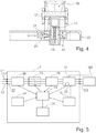
- Fig. 4 shows a schematic sectional illustration of part of an add-on housing arrangement 1 according to the invention.
- Fig. 4 On the one hand, the connector 100 is shown, the sleeve housing of which is fastened to the add-on housing by the locking bracket 12.
- the add-on housing arrangement 1 comprises a locking slide 17 and is equipped in the area of the cover 23 with a lifting magnet 20 and a plunger 21 as elements of the fixing 19.
- the cover 23 also has a position button 22 as a position detection for the locking slide 17 (and thus indirectly for the locking bracket 12).
- the locking slide 17 is resiliently mounted and follows the bracket movement in the vertical direction. The spring travel is so great that the slide 17 can follow the respective locking bracket 12 up to the locking position and there still exert a force on the bracket 12.
- the solenoid 20 can lock the slide 17 and thus the locking bracket 12.
- the plunger 21 of the lifting magnet 20 is pushed horizontally into the guide of the slide 17 (for example with a compression spring in the lifting magnet 20).
- the plunger armature 21 is extended and, when energized, is attracted.
- the position button 22 detects the position of the carriage 17.
- Fig. 5 shows a functional block diagram illustrating elements of an add-on housing arrangement 1 according to the invention.
- the add-on housing arrangement 1 comprises a mains connection 27, a current measuring unit 26, a contactor 15 as a switching interruption, a voltage measuring unit 16 and an add-on housing 11 (with a position detection 22), which through lines connected to the access lines L1, L2, L3 up to the plug contacts 102 of a on the attachment housing 11 plugged connector 100 extend.
- the add-on housing arrangement 1 further comprises a control unit 14, an operating unit 24 (in the form of a button, for example), an LED 25 as a signal output unit, and the locking arrangement 13.
- the separation 15 of the power circuit takes place between the function blocks of current measurement 26 and voltage measurement 16. As a result, the voltage can be measured on the machine side after the power circuit has been separated.
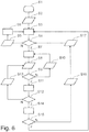
- the Fig. 6 shows a schematic flow diagram of an exemplary embodiment of the method according to the invention with locking and unlocking of a sleeve housing on an add-on housing.
- step S1 there is an initialization including a status check of the plug, lock and button.
- the LED as an example of a signal output unit, outputs a signal sequence “red”, “green”, “off” in the following step S2 in order to signal a successful initialization S1.
- step or state S3 the add-on housing arrangement is ready for operation, the contactor being open as an example of a switching interruption and the LED being switched off.
- step S4 it is checked whether the plug is inserted and the lock is locked and locked. If the result of this check is negative, the process proceeds to step S5, where a push of the button is also waited as an example of an operating unit. After pressing then follows step S6 with an unlocking, the locking being unlocked for 15 seconds when the LED flashes green. Then the process returns to step S3.
- step S7 the process goes into the operating state (step S7) in which the contactor is closed (i.e. continuously) and the LED lights up green in order to signal the operating state.
- step S8 When a key is pressed in step S8, a current measurement and a check follow in step S9 as to whether the current is less than a current permissible for the further method.
- step S10 in which the LED flashes red and green alternately for 10 seconds, after which the method returns to step S7.
- step S11 which follows if the result of the current test in step S9 is positive, the mains is switched off and the contactor is opened.
- the machine-side voltage ie the voltage present in the connector
- the machine-side voltage is measured for 10 seconds, for example, and a check is made to determine whether the amount of the voltage is less than a specified maximum permissible voltage.
- step S13 follows, in which the LED flashes red to indicate the corresponding signaling, after which the method returns to step S8.
- step S12 If the voltage is sufficiently low, the test in step S12 is followed by unlocking in step S14, with the locking of the locking brackets being released by the locking arrangement.
- step S15 a check is made to determine whether the plug has been pulled.
- step S16 If the plug has not been pulled, the LED is switched off in step S16 for the corresponding signal output and the method waits for the key to be pressed in step S17, after which it then continues to step S4.
- step S15 If the plug was pulled according to the test in step S15, the method returns to step S3.
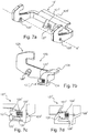
- FIG. 7a shows a locking bracket 12 'in the further embodiment.
- This locking bracket has a latching mechanism 127 '.
- This latching mechanism 127 ' has a spring-loaded retractable latching hook 121' which, in the locked state, serves to block the pivoting movement by latching the locking bracket 12 'on the add-on housing 11'.
- the latching hook 121' can be lowered into the locking bracket 12 '.
- the locking bracket 12 ' has a U-shaped basic shape with an actuating handle 129' and two side parts (not designated) extending perpendicularly therefrom.
- a cylindrical through opening 128 ' is provided as a fastening device for a bearing axis (not shown).
- the bearing axis itself is not shown, but if necessary runs along the axis A 'drawn in dashed lines.
- the Figure 7b shows the locking bracket 12 'in a sectional view, the section running perpendicular to the axis A' through the latching mechanism 127 '. Furthermore, the through opening 128 'can be clearly seen. This through opening 128 'forms the boundary between a locking area 12A and an actuating area 12B of the locking bracket 12', the actuating handle 129 'and the latching mechanism 127' belonging to the actuating area 12B.
- the locking bracket 12 'in the form of a rocker can be pivotably held on the add-on housing 11' via the bearing axis.
- the locking mechanism is arranged centrally on the actuation area 12B and has a receiving chamber 124 'for receiving the locking hook 121'.
- the receiving chamber 124 ' has a window 120'. Opposite the window 120 'it has a holding opening 123' in the form of a cylindrical through-hole. To facilitate assembly, it is advantageous that this bore is continuous, that is to say emerges from the locking bracket on the handle side.
- a cylindrical locking axis 126 ' is held displaceably with its first end in this holding opening 124' and protrudes with its second end into the interior of the receiving chamber 124 '.
- the latching hook 121 ' is attached to this second end, e.g. screwed on or molded on.
- the locking axis 126 ' passes through a spiral spring 122'.
- the spiral spring engages on the one hand on the area around the through opening 123 'and on the other hand on the latching hook 121'. As a result, it is set up to move the locking hook 121 'with a spring force corresponding to its deflection from its unlocking position through the window 120' of the receiving chamber 124 'into its locking position.
- the latching hook 121 ' has at its end protruding from the window 120' a slide-on bevel directed to the bottom left in the drawing and a latching surface directed upward in the drawing, by means of which it interacts with the corresponding locking arrangement 13 'in a latching manner when the locking bracket 12' is closed .
- the slide-on bevel and the locking surface are not provided with a reference symbol for reasons of clarity.
- the locked state of the latching mechanism 127 'shown in the figure is thus characterized in that the latching hook 121' with its latching surface protrudes far enough out of the window 120 'to be in a latching recess or at least on a counter-latching surface of the add-on housing 11' (see FIG Figure 8c ) to lock into place.
- the illustrated locked state of the locking mechanism 127 ' is thus characterized in that the locking hook 121' dips deep enough into the receiving chamber 124 'to unlock from the locking recess 134' or the counter-locking surface of the add-on housing 11 '.
- the Figure 8a shows the lifting magnet 20 'with its plunger 21' and a release lever 131 'movably attached to the plunger 21' via a pivot axis.
- a release hook 132 ' is formed on the end of the release lever 131'.
- the unlocking lever 131 'and the unlocking hook 132' are part of the modified locking arrangement 13 '. It can easily be seen that a plunger 21 'moving in the direction of the arrow automatically causes a lever movement of the unlocking lever 131'. As a result, the unlocking hook 132 'pushes the locking hook 121' deep enough into the receiving chamber 124 'to remove it from a locking recess 134' of the attachment housing 11 'and to separate its locking surface from the counter-locking surface of a locking device 133' of the attachment housing 11 '.
- the Figure 8c shows such an add-on housing 11 'with a latching device 133' through which a latching recess 134 'is formed.
- the unlocking lever 131 'with the unlocking hook 132' is arranged therein. It is easy to imagine how the locking bracket 12 ', which is locked on the locking device 133' by means of its locking mechanism 127 ', can be unlocked with the aid of the unlocking pin 132'.
Description
Die vorliegende Erfindung betrifft im Allgemeinen das Gebiet von Steckverbindungen und insbesondere das von Steckverbindungen im industriellen Umfeld. Konkret betrifft die vorliegende Erfindung eine Anbaugehäuseanordnung mit einem Anbaugehäuse zur Aufnahme eines Tüllengehäuses eines Steckverbinders mit Steckkontakten und einer mechanischen Verrieglungsanordnung zur mechanischen Verriegelung des Tüllengehäuses an dem Anbaugehäuse sowie ein Verfahren zur Entriegelung einer mechanischen Verrieglung eines Tüllengehäuses eines Steckverbinders mit Steckkontakten an einem Anbaugehäuse einer Anbaugehäuseanordnung.The present invention relates generally to the field of plug connections and in particular that of plug connections in the industrial environment. Specifically, the present invention relates to an add-on housing arrangement with an add-on housing for receiving a sleeve housing of a connector with plug contacts and a mechanical locking arrangement for mechanically locking the sleeve housing on the add-on housing and a method for unlocking a mechanical lock of a sleeve housing of a connector with plug contacts on an add-on housing.
Es sind Anordnungen bekannt, bei denen Tüllengehäuse und Anbaugehäuse einer Steckverbindung über eine mechanische Verriegelung miteinander verriegelt werden, wobei die Verriegelung insbesondere dahingehend von Bedeutung ist, dass die Steckverbindung gegen ein irrtümliches Lösen gesichert wird, so dass die Steckverbindung auch dann noch Bestand hat, wenn etwa ein gelegentlicher Zug an der Leitung auftritt, wobei die Verriegelung auch gegen ein Losrütteln durch Vibrationen wirksam ist.Arrangements are known in which the sleeve housing and the attachment housing of a plug connection are locked to one another via a mechanical lock, the locking being particularly important to the effect that the plug connection is secured against accidental loosening, so that the plug connection still exists when an occasional pull on the line occurs, the locking also being effective against shaking loose due to vibrations.
Die Druckschrift
Die Druckschrift
Die Druckschrift
Die Druckschrift
Die Druckschrift
Die Druckschrift
Ein der vorliegenden Erfindung zugrundeliegendes Ziel ist es, eine Anbauanordnung und ein Verfahren zur Entriegelung vorzustellen, die gegenüber dem bekannten Stand der Technik weiterentwickelt sind.It is an object of the present invention to present a mounting arrangement and a method for unlocking which have been further developed compared to the known prior art.
Erfindungsgemäß wird nach einem ersten Aspekt eine Anbaugehäuseanordnung vorgeschlagen, wie sie in Anspruch 1 definiert ist, nämlich mit einem Anbaugehäuse zur Aufnahme eines Tüllengehäuses eines Steckverbinders mit Steckkontakten, einer mechanischen Verrieglungsanordnung zur mechanischen Verriegelung des Tüllengehäuses an dem Anbaugehäuse, einer Arretieranordnung zur Arretierung der mechanischen Verriegelungsanordnung zumindest in einem verriegelnden Zustand und einer Steuereinheit zur Steuerung der Arretieranordnung, wobei die Steuereinheit dazu ausgestaltet ist, die Arretieranordnung nur dann zur Freigabe einer Arretierung der Verriegelungsanordnung anzusteuern, wenn die Steckkontakte innerhalb vorgegebener Toleranzen strom- und spannungsfrei sind.According to the invention, according to a first aspect, an add-on housing arrangement is proposed as defined in
Erfindungsgemäß wird nach einem zweiten Aspekt ein Verfahren zur Entriegelung einer mechanischen Verrieglung eines Tüllengehäuses eines Steckverbinders mit Steckkontakten an einem Anbaugehäuse einer Anbaugehäuseanordnung vorgeschlagen, wie es in Anspruch 11 definiert ist, nämlich ein Verfahren, bei dem die Anbaugehäuseanordnung eine Arretieranordnung umfasst, die die mechanische Verriegelungsanordnung in einem verriegelnden Zustand arretiert und mit den Schritten des Prüfens auf eine Strom- und Spannungsfreiheit der Steckkontakte innerhalb vorgegebener Toleranzen, des Freigebens der Arretierung der Verriegelungsanordnung durch die Arretieranordnung nach dem Prüfen, wenn die Steckkontakte innerhalb der vorgegebenen Toleranzen strom- und spannungsfrei sind, und des Entriegelns der Verriegelung des Tüllengehäuses nach dem Freigeben der Arretierung.According to a second aspect of the invention, a method for unlocking a mechanical locking of a sleeve housing of a connector with plug contacts on an add-on housing of an add-on housing arrangement is proposed, as is defined in
Ein Teil des Hintergrunds der vorliegenden Erfindung findet sich in den folgenden Überlegungen.Part of the background to the present invention resides in the following considerations.
Mit Hilfe der mechanischen Verrieglungsanordnung besteht eine Sicherung gegen ein unbeabsichtigtes Lösen der Steckverbindung, etwa bei einem Zug auf die Leitung oder durch Vibrationen im Betrieb, so dass eine gegenüber einer Steckverbindung ohne eine Verrieglung verbesserte Betriebssicherheit gegeben ist. Die herkömmlich direkt durch einen Benutzer zu lösende Verriegelung stellt allerdings keine Sicherheit gegen eine bewusst herbeigeführte Lösung der Steckverbindung bereit, die als solche mit einem Sicherheitsrisiko für den Betrieb und insbesondere den Benutzer verbunden sein kann.With the help of the mechanical locking arrangement, there is a safeguard against unintentional loosening of the plug connection, for example when the line is pulled or due to vibrations during operation, so that operational reliability is improved compared to a plug connection without a lock. The lock, which is conventionally to be released directly by a user, does not provide any security against a deliberately brought about release of the plug connection, which as such can be associated with a security risk for the operation and in particular for the user.
Es wurde gefunden, dass es wünschenswert ist, den Umgang mit einer Steckverbindung dahingehend weiterzuentwickeln, dass eine bessere Sicherheit gegeben ist, wobei im Rahmen der Erfindung sichergestellt werden soll, dass der Steckverbinder nicht unter Last gezogen werden kann und dass auch bei einer an sich getrennten/abgeschalteten Last auch maschinenseitig keine gefährliche Spannung (mehr) anliegt.It has been found that it is desirable to further develop the handling of a plug connection in such a way that better security is provided, whereby within the scope of the invention it is to be ensured that the plug connector cannot be pulled under load and that even in the case of an intrinsically separated / when the load is switched off, there is no (longer) dangerous voltage on the machine either.
Insbesondere bei einer Ausgestaltung der Erfindung mit einer Kombination von Verriegelung des Steckverbinders, Messung von Strom/Spannung und Sensoren die den Zustand des Gerätes erfassen, können diese technischen Merkmale miteinander interagieren und das Verfahren der Ver- bzw. Entriegelung charakterisieren.In an embodiment of the invention with a combination of locking the connector, measuring current / voltage and sensors that detect the state of the device, these technical features can interact with one another and characterize the locking and unlocking method.
Es kann mit der Erfindung besser sichergestellt werden, dass der Steckverbinder nicht unter Last gezogen wird, wobei vorzugsweise erreicht wird, dass im ungesteckten Zustand die netzseitigen Leistungskontakte immer spannungsfrei geschaltet sind. Vor dem Entriegelungsvorgang wird auch die Maschinenseite auf Spannungsfreiheit geprüft. Insbesondere solange maschinenseitig (noch) eine eventuell gefährliche Restspannung anliegt bleibt der Mechanismus verriegelt. Die Personen- und Maschinenschutz kann mit der Erfindung daher verbessert werden.It can be better ensured with the invention that the plug connector is not pulled under load, whereby it is preferably achieved that in the unplugged state the power contacts on the mains side are always switched to a voltage-free state. Before the In the unlocking process, the machine side is also checked to ensure that there is no voltage. The mechanism remains locked, especially as long as a potentially dangerous residual voltage is (still) present on the machine side. The protection of people and machines can therefore be improved with the invention.
In einer vorteilhaften Ausgestaltung eines Aspekts der Erfindung umfasst die Anbaugehäuseanordnung ferner eine Schaltunterbrechung, insbesondere einem Schütz, zur Unterbrechung einer Leitung, die zu einem Steckkontakt führt, und eine Spannungsmesseinheit zur Messung einer an dem Steckkontakt anliegenden Spannung, wobei die Spannungsmesseinheit hinsichtlich der Leitung zwischen der Schaltunterbrechung und dem Steckkontakt angeordnet ist.In an advantageous embodiment of an aspect of the invention, the add-on housing arrangement further comprises a circuit breaker, in particular a contactor, for interrupting a line leading to a plug contact, and a voltage measuring unit for measuring a voltage applied to the plug contact, the voltage measuring unit with regard to the line between the Switching interruption and the plug contact is arranged.
Mit Hilfe der Schaltunterbrechung kann eine Trennung der Steckverbindung gegenüber der Netzseite erreicht werden, wobei die Spannungsmesseinheit zwischen der Schaltunterbrechung und den Steckkontakten dazu dient, eine auch im an sich ausgeschalteten Zustand möglicherweise noch anliegende (Rest-)Spannung zu erfassen, um in diesem Fall eine Gefährdung durch diese (Rest-)Spannung zu vermeiden, die ansonsten bei einem Lösen der Steckverbindung zugänglich würde.With the help of the switching interruption, the plug connection can be separated from the mains side, with the voltage measuring unit between the switching interruption and the plug contacts being used to detect any (residual) voltage that may still be present in the switched-off state Avoid danger from this (residual) voltage, which would otherwise be accessible if the plug-in connection was loosened.
In einer anderen vorteilhaften Ausgestaltung eines Aspekts der Erfindung weist die mechanische Verrieglungsanordnung wenigstens einen Verriegelungsbügel auf, der im verriegelten Zustand mit dem Tüllengehäuse in Eingriff steht, wobei die Arretieranordnung einen Arretierschlitten, der durch eine Federbelastung an den Verrieglungsbügel angelegt ist, und eine Festlegung für den Arretierschlitten in einer an dem im verriegelnden Zustand befindlichen Verriegelungsbügel anliegenden Position aufweist.In another advantageous embodiment of an aspect of the invention, the mechanical locking arrangement has at least one locking bracket which is in engagement with the spout housing in the locked state, the locking arrangement having a locking slide which is applied to the locking bracket by a spring load, and a definition for the Has locking slide in a position resting against the locking bracket in the locked state.
Die Nutzung von Verriegelungsbügeln zur Verriegelung als solche ist bekannt, wobei allerdings bekannte Verriegelungsbügel vorteilhafterweise mit einem festlegbaren Arretierschlitten zum Einsatz im Rahmen der vorliegenden Erfindung weitergebildet werden können, ohne dass eine Modifikation am Verrieglungsbügel selbst nötig wäre. Dies erlaubt, herkömmliche Anbaugehäuse auch im Rahmen der Erfindung nutzen zu können.The use of locking brackets for locking is known as such, although known locking brackets can advantageously be further developed with a fixable locking slide for use within the scope of the present invention without a modification to the locking bracket itself being necessary. This allows conventional add-on housings to be used within the scope of the invention.
Bei einem dem Verriegelungsbügel infolge einer Federbelastung folgenden Arretierschlitten und einer Festlegung des Arretierschlittens wird der Verriegelungsbügel nur indirekt festgelegt.In the case of a locking slide following the locking bracket as a result of a spring load and a fixing of the locking slide, the locking bracket is only fixed indirectly.
Im Rahmen der vorliegenden Erfindung ist es allerdings auch möglich, eine direkte Festlegung des Verriegelungsbügels selbst vorzusehen.In the context of the present invention, however, it is also possible to provide a direct fixing of the locking bracket itself.
Es können auch andere Ansätze genutzt werden, um den Arretierschlitten oder ein vergleichbares Element dazu auszugestalten, dass er möglichst durchgehend an dem Verriegelungsbügel anliegt, etwa durch eine magnetische Kopplung oder auch eine direkte Verbindung, bei der der Arretierschlitten am Verriegelungsbügel selbst befestigt ist.Other approaches can also be used to design the locking slide or a comparable element so that it rests as continuously as possible on the locking bracket, for example by means of a magnetic coupling or a direct connection in which the locking slide is attached to the locking bracket itself.
In einer besonders vorteilhaften Ausgestaltung kann der Verriegelungsbügel selbst eine Rastmechanik zu seiner Fixierung im verriegelnden Zustand besitzen. Insbesondere kann der Verriegelungsbügel Rastmittel, insbesondere einen federbeaufschlagt versenkbaren Rasthaken, zum Sperren der Schwenkbewegung des Verriegelungsbügels in seinem verriegelnden Zustand aufweisen. Dazu ist es besonders vorteilhaft, wenn der Verriegelungsbügel einen Verriegelungsbereich und einen Betätigungsbereich besitzt, zwischen denen eine Lagerachse angeordnet ist. Über diese Lagerachse kann der Verriegelungsbügel besonders vorteilhaft in Form einer Wippe schwenkbar an dem Anbaugehäuse gehalten sein. Die Rastmechanik kann dann vorteilhafterweise im oder am Betätigungsbereich des Verriegelungsbügels angeordnet sein und kann insbesondere Bestandteil dieses Betätigungsbereichs sein.In a particularly advantageous embodiment, the locking bracket itself can have a latching mechanism for fixing it in the locking state. In particular, the locking bracket can have latching means, in particular a spring-loaded retractable latching hook, for locking the pivoting movement of the locking bracket in its locking state. For this purpose, it is particularly advantageous if the locking bracket has a locking area and an actuating area, between which a bearing axis is arranged. The locking bracket can particularly advantageously be held pivotably on the add-on housing in the form of a rocker via this bearing axis. The latching mechanism can then advantageously be arranged in or on the actuation area of the locking bracket and can in particular be part of this actuation area.
Dies hat den Vorteil, dass zur Verriegelung des Tüllengehäuses einerseits der Betätigungsbereich des Verriegelungsbügels zum Anbaugehäuse hinbewegt werden kann, während dadurch andererseits der Verriegelungsbereich des Verriegelungsbügels in entgegengesetzter Richtung, sich also vom Anbaugehäuse wegbewegend, mit seinen rückläufigen Verriegelungsenden über Rastzapfen des Tüllengehäuses geschwenkt wird, um das Tüllengehäuse am Anbaugehäuse zu verriegeln. In diesem verriegelnden Zustand befindet sich der Verriegelungsbügel dann mit seinem Betätigungsbereich und insbesondere mit seiner Rastmechanik zumindest in der Nähe des Anbaugehäuses und kann so in besonders vorteilhafter Weise an der entsprechend modifizierten Arretieranordnung des Anbaugehäuses verrasten.This has the advantage that to lock the sleeve housing, on the one hand, the actuation area of the locking bracket can be moved towards the attachment housing, while on the other hand the locking area of the locking bracket is pivoted in the opposite direction, i.e. moving away from the attachment housing, with its reverse locking ends via locking pins of the sleeve housing to lock the sleeve housing on the add-on housing. In this locking state, the locking bracket is then with its actuation area and in particular with its locking mechanism at least in the vicinity of the add-on housing and can thus latch in a particularly advantageous manner on the correspondingly modified locking arrangement of the add-on housing.
Insbesondere kann der Verriegelungsbügel eine U-förmige Grundform mit einem Betätigungsgriff und zwei sich senkrecht davon erstreckenden Seitenteilen aufweisen, wobei die frei stehenden Enden der Seitenteile (also endseitig) den Verriegelungsbereich ausbilden. Der Betätigungsgriff gehört dagegen zum Betätigungsbereich. In den beiden Seitenteilen kann sich jeweils eine Befestigungsvorrichtung für die Lagerachse befinden. Diese Befestigungsvorrichtung kann z.B. in je einer zylinderförmigen Durchgangsöffnung als endseitige Aufnahme für die Lagerachse, bestehen. Die Lagerachse und insbesondere die dafür vorgesehene Befestigungseinrichtung der Seitenteile kann somit als Grenze zwischen dem Betätigungs- und dem Verriegelungsbereich des Verriegelungsbügels angesehen werden.In particular, the locking bracket can have a U-shaped basic shape with an actuating handle and two side parts extending perpendicularly therefrom, the free ends of the side parts (that is to say at the ends) forming the locking area. The operating handle, on the other hand, belongs to the operating area. A fastening device for the bearing axis can be located in each of the two side parts. This fastening device can, for example, consist of a cylindrical through opening each as an end receptacle for the bearing axis. The bearing axis and in particular the fastening device provided for the side parts can thus be viewed as the boundary between the actuation area and the locking area of the locking bracket.
In einer bevorzugten Ausgestaltung kann die Arretieranordnung des Anbaugehäuses derart modifiziert sein, dass sie einen Entrastungshebel aufweist, der mit einem Tauchanker eines Hubmagneten verbunden ist. An das Ende des Entrastungshebels kann ein Entrastungshaken zum Zusammenwirken mit der Rastmechanik angeformt sein. Zur Entriegelung kann mittels dieses Entrastungshebels und insbesondere mittels des Entrastungshakens der besagte Rasthaken federbeaufschlagt in dem Verriegelungsbügel, insbesondere in einer dafür vorgesehenen Aufnahmekammer, versenkt, also mit anderen Worten in den Verriegelungsbügel hineingeschoben, werden, um den Verriegelungsbügel von der Verrastung freizugeben. Daraufhin kann der Verriegelungsbügel händisch gelöst, also von seiner verriegelnden in seine entriegelnde Position überführt, werden.In a preferred embodiment, the locking arrangement of the add-on housing can be modified in such a way that it has a release lever which is connected to a plunger of a lifting magnet. A disengaging hook for interacting with the locking mechanism can be molded onto the end of the unlocking lever. For unlocking, by means of this unlocking lever and in particular by means of the unlocking hook, the said locking hook can be spring-loaded into the locking bracket, in particular in a receiving chamber provided for this purpose, sunk, in other words, pushed into the locking bracket, in order to release the locking bracket from latching. The locking bracket can then be released manually, that is to say transferred from its locking position to its unlocking position.
Die vorausgegangene Entrastung kann somit durch den Hubmagneten, also letztlich z.B. durch ein elektrisches Signal, insbesondere einen elektrischen Stromfluss durch eine Spule des Hubmagneten, bewirkt werden. Im Normalzustand, d.h. wenn kein derartiges elektrisches Signal existiert, befindet sich der Rasthaken der Rastmechanik durch die Federkraft automatisch in seiner Verrastungsposition. Dies ist aus Sicherheitsgründen besonders vorteilhaft, weil so eine unbeabsichtigte Entriegelung z.B. in Folge eines Stromausfalls, also z.B. durch eine Trennung des entsprechenden Kontakts von einer entsprechenden Stromquelle, etc. vermieden wird. Im Normalzustand verrastet der Verriegelungsbügel dann in seiner verriegelnden Stellung. Zur Freigabe des Verriegelungsbügels muss dementsprechend ein Strom, z.B. durch die Spule des Hubmagneten, fließen.The previous unlocking can thus be effected by the lifting magnet, i.e. ultimately, for example, by an electrical signal, in particular an electrical current flow through a coil of the lifting magnet. In the normal state, i.e. when there is no such electrical signal, the locking hook of the locking mechanism is automatically in its locking position due to the spring force. This is particularly advantageous for safety reasons, because it avoids unintentional unlocking, e.g. as a result of a power failure, e.g. by disconnecting the corresponding contact from a corresponding power source, etc. In the normal state, the locking bracket then latches in its locking position. To release the locking bracket, a current must flow accordingly, e.g. through the coil of the lifting magnet.
Die Rastmechanik kann eine bevorzugt zentral in dem Betätigungsbereich des Verrieglungsbügels angeordnete Aufnahmekammer zur Aufnahme des Rasthakens aufweisen. Die Aufnahmekammer kann ein im verriegelten Zustand in Richtung der Arretieranordnung weisendes Fenster besitzen. Dem Fenster gegenüberliegend kann die Aufnahmekammer eine Halteöffnung, insbesondere in Form einer zylinderförmigen Bohrung, aufweisen. In dieser Halteöffnung kann eine, insbesondere zylinderförmige, Verriegelungsachse mit ihrem ersten Ende verschiebbar gehalten sein, wobei die Verriegelungsachse mit einem dem ersten Ende gegenüberliegenden zweiten Ende ins Innere der Aufnahmekammer hineinragt. An diesem zweiten Ende kann der Rasthaken angebracht, z.B. angeschraubt oder angeformt, sein.The latching mechanism can have a receiving chamber, which is preferably arranged centrally in the actuation area of the locking bracket, for receiving the latching hook. The receiving chamber can have a window pointing in the direction of the locking arrangement in the locked state. Opposite the window, the receiving chamber can have a holding opening, in particular in the form of a cylindrical bore. In this holding opening a, in particular cylindrical, locking axis can be held displaceably with its first end, the locking axis protruding into the interior of the receiving chamber with a second end opposite the first end. The latching hook can be attached to this second end, for example screwed on or molded on.
Die besagte Federbeaufschlagung des Rasthakens kann dann bevorzugt durch eine Spiralfeder erzeugt werden. Dazu kann die Verriegelungsachse die Spiralfeder durchgreifen. Die Spiralfeder kann einerseits an einer Innenwand der Aufnahmekammer an dem Bereich um die Halteöffnung und andererseits am Rasthaken angreifen. Dadurch ist sie dazu eingerichtet, den Rasthaken mit der Federkraft der Spiralfeder aus seiner Entriegelungsposition zumindest teilweise durch das Fenster in seine Verrastungsposition zu verschieben. Der Rasthaken besitzt an seinem aus dem Fenster herausragenden Ende eine Aufgleitschräge und eine Rastfläche, durch die er beim Schließen des Verriegelungshebels mit der Arretieranordnung verriegelnd zusammenwirkt. Dieses Zusammenwirken kann derart gestaltet sein, dass der Verriegelungsbügel beim Schließen des Verriegelungsbügels durch seine Aufgleitschräge zunächst entgegen der Federkraft in die Aufnahmekammer hineingeschoben wird, um dann durch die Federkraft der Spiralfeder in einer Rastausnehmung zu gleiten oder zumindest an einer Verriegelungsfläche einer Rastvorrichtung des Anbaugehäuses zu verrasten. An die Verriegelungsachse grenzend kann der Rasthaken zumindest eine vom Innen in Richtung des Fensters gerichtete Stufe als Anschlag aufweisen, so dass er durch die Federkraft der Spiralfeder nicht vollständig aus dem Fenster gedrückt werden kann.Said spring loading of the locking hook can then preferably be generated by a spiral spring. For this purpose, the locking axis can reach through the spiral spring. The spiral spring can act on the one hand on an inner wall of the receiving chamber in the area around the holding opening and on the other hand on the latching hook. As a result, it is set up to move the latching hook with the spring force of the spiral spring from its unlocking position at least partially through the window into its latching position. At its end protruding from the window, the latching hook has a slide-on bevel and a latching surface through which it interacts in a locking manner with the locking arrangement when the locking lever is closed. This interaction can be designed in such a way that the locking bracket is initially pushed into the receiving chamber against the spring force by its slide-on slope when the locking bracket is closed, in order then to slide into a latching recess by the spring force of the spiral spring or at least to latch on a locking surface of a latching device of the add-on housing . Adjacent to the locking axis, the latching hook can have at least one step directed from the inside in the direction of the window as a stop, so that it cannot be pushed completely out of the window by the spring force of the spiral spring.
Herkömmlich werden oft zwei einander gegenüberliegende Verriegelungsbügel eingesetzt, wobei diese vorzugsweise (aber nicht notwendig) beide so wie hier beschrieben ausgestaltet sind.Conventionally, two opposing locking brackets are often used, these preferably (but not necessarily) both being designed as described here.
In einer anderen vorteilhaften Ausgestaltung eines Aspekts der Erfindung ist eine Positionserfassung vorgesehen, die dazu ausgestaltet ist, zu erfassen, ob sich die Verrieglungsanordnung in dem verriegelnden Zustand befindet.In another advantageous embodiment of an aspect of the invention, a position detection is provided which is designed to detect whether the locking arrangement is in the locking state.
Die Positionserfassung meldet den Zustand bzgl. der Verriegelung an die Steuereinheit, die dann entsprechende Steuerungen vornehmen kann.The position detection reports the status with regard to the locking to the control unit, which can then carry out appropriate controls.
In einer bevorzugten Variante der obigen Ausgestaltung umfasst die Anbaugehäuseanordnung eine Schaltunterbrechung, insbesondere einem Schütz, zur Unterbrechung einer Leitung, die zu einem Steckkontakt führt, wobei die Steuereinheit zur Steuerung der Schaltunterbrechung ausgestaltet ist, wobei die Steuereinheit die Schaltunterbrechung nur dann zu einem Schließen der Leitung ansteuern, wenn die Positionserfassung erfasst, dass sich die Verriegelungsanordnung in dem verriegelnden Zustand befindet.In a preferred variant of the above embodiment, the add-on housing arrangement comprises a switching interruption, in particular a contactor, for interrupting a line that leads to a plug contact, the control unit being designed to control the switching interruption, the control unit only activating the switching interruption when the line is closed drive when the position detection detects that the locking arrangement is in the locking state.
So kann die Information hinsichtlich des Verriegelungszustands dazu genutzt werden, zu verhindern, dass eine netzseitige Spannung zu den Kontakten im Anbaugehäuse gelangt, während die Steckverbindung selbst noch nicht erreicht ist.The information regarding the locking status can thus be used to prevent a line-side voltage from reaching the contacts in the add-on housing while the plug connection itself has not yet been reached.
In einer vorteilhaften Weiterbildung der obigen Variante umfasst die Anbaugehäuseanordnung eine Bedieneinheit, wobei die Steuereinheit dazu ausgestaltet ist, die Schaltunterbrechung nur in Antwort auf eine Bedienung der Bedieneinheit zum Schließen der Leitung anzusteuern.In an advantageous development of the above variant, the add-on housing arrangement comprises an operating unit, the control unit being designed to control the switching interruption only in response to an operation of the operating unit to close the line.
Wird zusätzliche eine Bedienung durch einen Benutzer als Bedingung für ein Freigeben der netzseitigen Spannung bzw. des Netzstroms an die Steckverbindung vorgesehen, erhöht dies weiter die allgemeine Sicherheit.If an operation by a user is also provided as a condition for releasing the line-side voltage or the line current to the plug-in connection, this further increases the general safety.
In einer anderen vorteilhaften Ausgestaltung eines Aspekts der Erfindung weist die Anbaugehäuseanordnung eine Bedieneinheit auf, wobei die Steuereinheit dazu ausgestaltet ist, die Arretieranordnung nur in Antwort auf eine Bedienung der Bedieneinheit zur Freigabe der Arretierung der Verriegelungsanordnung anzusteuern.In another advantageous embodiment of an aspect of the invention, the add-on housing arrangement has an operating unit, the control unit being designed to control the locking arrangement only in response to an operation of the operating unit to release the locking of the locking arrangement.
Im Rahmen dieser Ausgestaltung sind wenigstens zwei voneinander unabhängige Bedienungen vorgesehen, nämlich die Bedienung der Bedieneinheit, z.B. im Form eines Drückens eines Tasters oder dergleichen, und das Lösen der Verriegelung, so dass auch hiermit eine insgesamt bessere Sicherheit erreicht werden kann.In the context of this embodiment, at least two independent controls are provided, namely the operation of the control unit, e.g. in the form of pressing a button or the like, and the release of the lock, so that overall better security can be achieved with this too.
In einer anderen vorteilhaften Ausgestaltung eines Aspekts der Erfindung ist eine Signalausgabeeinheit vorgesehen, die dazu ausgestaltet ist, ein einen Betriebszustand der Anbaugehäuseanordnung angebendes Signal auszugebenIn another advantageous embodiment of an aspect of the invention, a signal output unit is provided which is designed to output a signal indicating an operating state of the add-on housing arrangement
Die Nutzung einer Signalausgabe erlaubt es dem Benutzer in einfacher Weise den Zustand der Steckverbindung bzw. der Anordnung als Ganzes zu erkennen, so dass der Benutzer auch erkennen kann, welche Schritte derzeit möglich sind bzw. welche Schritte ggf. nötig sind, um beispielsweise die Steckverbindung zu lösen.The use of a signal output allows the user to easily recognize the state of the plug connection or the arrangement as a whole, so that the user can also see which steps are currently possible or which steps may be necessary, for example to adjust the plug connection to solve.
Gemäß einem weiteren Aspekt der vorliegenden Erfindung ist ein Computerprogramm mit Programmmitteln vorgesehen, die die Steuereinheit einer erfindungsgemäßen Anbaugehäuseanordnung dazu veranlassen, die Arretierung der Verriegelungsanordnung durch die Arretieranordnung nach einem Prüfen auf eine Strom- und Spannungsfreiheit der Steckkontakte innerhalb vorgegebener Toleranzen freigeben zu lassen, wenn die Steckkontakte innerhalb der vorgegebenen Toleranzen strom- und spannungsfrei sind, wenn das Computerprogramm von der Steuereinheit ausgeführt wird.According to a further aspect of the present invention, a computer program with program means is provided which cause the control unit of an add-on housing arrangement according to the invention to release the locking of the locking arrangement by the locking arrangement after checking that the plug contacts are free of current and voltage within specified tolerances if the Plug contacts are free of current and voltage within the specified tolerances when the computer program is executed by the control unit.
Merkmale vorteilhafter Ausführungsformen der Erfindung sind insbesondere in den Unteransprüchen definiert, wobei weitere vorteilhafte Merkmale, Ausführungen und Ausgestaltungen für den Fachmann zudem aus den obigen Erläuterung und der folgenden Diskussion zu entnehmen sind.Features of advantageous embodiments of the invention are defined in particular in the subclaims, further advantageous features, designs and configurations for the person skilled in the art can also be taken from the above explanation and the following discussion.
Im Folgenden wird die vorliegende Erfindung anhand von in den Figuren dargestellten Ausführungsbeispielen weiter illustriert und erläutert. Hierbei zeigt
- Fig. 1
- eine Ansicht einer Anbaugehäuseanordnung gemäß einem Ausführungsbeispiel der Erfindung,
- Fig. 2
- eine weitere, teiltransparent dargestellte Ansicht der Anbaugehäuseanordnung aus
Fig. 1 , - Fig. 3
- eine Darstellung eines Deckels mit Anbaugehäuse der Anbaugehäuseanordnung aus
Fig. 1 , - Fig. 4
- eine schematische Schnittdarstellung eines Teils einer erfindungsgemäßen Anbaugehäuseanordnung,
- Fig. 5
- ein funktionelles Blockdiagramm, das Elemente einer erfindungsgemäßen Anbaugehäuseanordnung illustriert,
- Fig. 6
- ein schematisches Ablaufdiagramm eines Ausführungsbeispiels des erfindungsgemäßen Verfahrens mit einer Ver- und Entriegelung eines Tüllengehäuses an einem Anbaugehäuse,
- Fig. 7a-d
- einen Verriegelungsbügel mit einer Rastmechanik in einer weiteren Ausführung, und
- Fig. 8a-c
- eine dazugehörige, Arretieranordnung in der weiteren Ausführung.
- Fig. 1
- a view of an add-on housing arrangement according to an embodiment of the invention,
- Fig. 2
- Another, partially transparent view of the add-on housing arrangement
Fig. 1 , - Fig. 3
- a representation of a cover with add-on housing of the add-on housing arrangement
Fig. 1 , - Fig. 4
- a schematic sectional view of part of an add-on housing arrangement according to the invention,
- Fig. 5
- a functional block diagram illustrating elements of an add-on housing assembly according to the invention,
- Fig. 6
- a schematic flow diagram of an embodiment of the method according to the invention with a locking and unlocking of a sleeve housing on an add-on housing,
- Figures 7a-d
- a locking bracket with a locking mechanism in a further embodiment, and
- Figures 8a-c
- an associated locking arrangement in the further version.
In den beiliegenden Zeichnungen sowie den Erläuterungen zu diesen Zeichnungen sind einander entsprechende bzw. in Beziehung stehende Elemente - soweit zweckdienlich - mit jeweils entsprechenden oder ähnlichen Bezugszeichen gekennzeichnet, auch wenn sie in unterschiedlichen Ausführungsbeispielen zu finden sind.In the accompanying drawings and the explanations of these drawings, elements that correspond or are related to one another are identified - as far as appropriate - with corresponding or similar reference numerals, even if they are to be found in different exemplary embodiments.
Die Anbaugehäuseanordnung 1 umfasst einen Netzanschluss 27 und einen Ethernetanschluss 28 und ist mit einer Bedieneinheit 24 in Form eines Tasters ausgestattet. An der Anbaugehäuseanordnung 1 befindet sich ein Anbaugehäuse 11, das - in an sich bekannter Weise - mit Verriegelungsbügeln 12 ausgestattet ist.The add-on
Abweichend von den bekannten Lösungen ist die Anbaugehäuseanordnung 1 zudem mit einer Arretieranordnung 13 versehen, mit der die Verriegelungsbügel 12 in einem verriegelnden Zustand festgelegt werden können.Deviating from the known solutions, the add-on
Weitere Elemente der Anbaugehäuseanordnung 1 werden weiter unten mit Bezug auf weitere Figuren beschrieben.Further elements of the add-on
Die Anbaugehäuseanordnung 1 kann auch als "Wall Box" bezeichnet werden und ist hier mit einem auf das Anbaugehäuse 11 aufgestecktem Stecker 100 mit einem Tüllengehäuse 101 dargestellt.The add-on
Die Pfeile zeigen schematisch die Zufuhr von Leistung zum Netzanschluss 27 und Ethernetsignalen zum Ethernetanschluss 28, wobei das Kabel (nicht gezeigt), das am Steckverbinder 100 angebracht ist, ein Hybridkabel zur Übermittlung von Leistung und Ethernetsignalen gemeinsam ist.The arrows show schematically the supply of power to the
Die Arretieranordnung 13 arretiert die Verriegelungsbügel 12 und verhindert ein Ziehen des Steckverbinders 100 unter Last. Nur wenn kein Strom fließt und im Steckbereich keine gefährliche Spannung anliegt, kann durch das Betätigen des Tasters 24 als einem Bespiel einer Bedieneinheit der Verriegelungsmechanismus entriegeln (die Arretieranordnung die Arretierung der Verriegelungsbügel freigeben). Nun können die Verriegelungsbügel geöffnet und der Stecker gezogen werden, dass sich ein guter Personen- und Maschinenschutz ergibt.The locking
Die Anbaugehäuseanordnung 1 umfasst einen Deckel 23, der mit dem Anbaugehäuse 11 versehene ist. Der Deckel 23 schließt einen Innenraum der Anbaugehäuseanordnung 1 ab, in dem unter anderem eine Platine mit einer Schaltunterbrechung 15 in Form eines Schütz und auch die Festlegung 19 der Arretieranordnung 13untergebracht ist. Der Deckel 23 ist zudem mit dem Taster 24 versehen.The add-on
Insbesondere in
Im Deckel 23 ist die Geometrie eines Anbaugehäuses 11 integriert; hierdurch ist das entsprechende Tüllengehäuse 101 (siehe
In
Die Anbaugehäuseanordnung 1 umfasst, wie schon oben diskutiert, einen Arretierschlitten 17 und ist im Bereich des Deckels 23 mit einem Hubmagneten 20 und einem Tauchanker 21 als Elemente der Festlegung 19 ausgestattet. Der Deckel 23 weist zudem einen Positionstaster 22 als eine Positionserfassung für den Arretierschlitten 17 (und damit indirekt für die Verriegelungsbügel 12).As already discussed above, the add-on
Der Arretierschlitten 17 ist federnd gelagert und folgt der Bügelbewegung in vertikaler Richtung. Der Federweg ist so groß, dass der Schlitten 17 dem jeweiligen Verriegelungsbügel 12 bis zur Verriegelungsstellung folgen kann und dort immer noch eine Kraft auf den Bügel 12 ausübt. In der Verriegelungsstellung (siehe
Die Anbaugehäuseanordnung 1 umfasst einen Netzanschluss 27, eine Strommesseinheit 26, einen Schütz 15 als Schaltunterbrechung, eine Spannungsmesseinheit 16 und ein Anbaugehäuse 11 (mit einer Positionserfassung 22), die durch mit den Zugangsleitungen L1, L2, L3 verbundenen Leitungen bis zu den Steckkontakten 102 eines an dem Anbaugehäuse 11 angesteckten Steckverbinders 100 verlaufen.The add-on
Die Anbaugehäuseanordnung 1 umfasst weiter eine Steuereinheit 14, eine Bedieneinheit 24 (in Form etwa eines Tasters), eine LED 25 als eine Signalausgabeeinheit und die Arretieranordnung 13.The add-on
Die Interaktion der Elemente untereinander wird auch anhand der folgenden Beschreibung von
Die Trennung 15 des Leistungsstromkreises erfolgt zwischen den Funktionsblöcken Strommessung 26 und Spannungsmessung 16. Hierdurch kann nach der Trennung des Leistungskreises maschinenseitig die Spannung gemessen werden.The
Zudem zeigen die Funktionsblöcke in der
Die
In Schritt S1 erfolgt eine Initialisierung einschließlich einer Zustandsüberprüfung von Stecker, Verriegelung und Taster.In step S1 there is an initialization including a status check of the plug, lock and button.
Die LED als ein Beispiel einer Signalausgabeeinheit gibt im folgenden Schritt S2 eine Signalfolge "Rot", "Grün", "Aus" aus, um eine erfolgreiche Initialisierung S1 zu signalisieren.The LED, as an example of a signal output unit, outputs a signal sequence “red”, “green”, “off” in the following step S2 in order to signal a successful initialization S1.
In Schritt oder Zustand S3 ist die Anbaugehäuseanordnung betriebsbereit, wobei das Schütz als ein Beispiel einer Schaltunterbrechung geöffnet ist und die LED ausgeschaltet ist.In step or state S3, the add-on housing arrangement is ready for operation, the contactor being open as an example of a switching interruption and the LED being switched off.
Im Schritt S4 wird geprüft, ob der Stecker gesteckt und die Verriegelung verriegelt und arretiert ist. Wenn das Ergebnis dieser Prüfung negativ ist, schreitet der Prozess zu Schritt S5 fort, wo auch ein Drücken des Tasters als ein Beispiel einer Bedieneinheit gewartet wird. Nach dem Drücken folgt dann Schritt S6 mit einer Entriegelung, wobei die Arretierung bei grün blinkender LED für 15 Sekunden entriegelt ist. Dann kehrt der Prozess zu Schritt S3 zurück.In step S4 it is checked whether the plug is inserted and the lock is locked and locked. If the result of this check is negative, the process proceeds to step S5, where a push of the button is also waited as an example of an operating unit. After pressing then follows step S6 with an unlocking, the locking being unlocked for 15 seconds when the LED flashes green. Then the process returns to step S3.
Bei einem positiven Prüfergebnis in Schritt S4 gelangt der Prozess in den Betriebszustand (Schritt S7), bei dem der Schütz geschlossen (also durchgängig) ist und die LED grün leuchtet, um so den Betriebszustand zu signalisieren.If the test result in step S4 is positive, the process goes into the operating state (step S7) in which the contactor is closed (i.e. continuously) and the LED lights up green in order to signal the operating state.
Bei Drücken einer Taste in Schritt S8 folgt in Schritt S9 eine Strommessung und eine Prüfung, ob der Strom geringer als ein für das weitere Verfahren zulässiger Strom ist.When a key is pressed in step S8, a current measurement and a check follow in step S9 as to whether the current is less than a current permissible for the further method.
Ist der Strom zu hoch, wird das Verfahren mit Schritt S10 fortgesetzt, in dem die LED abwechselnd für 10 Sekunden rot und grün blinkt, wonach das Verfahren zu Schritt S7 zurückkehrt.If the current is too high, the method continues with step S10, in which the LED flashes red and green alternately for 10 seconds, after which the method returns to step S7.
In Schritt S11, der bei positivem Ergebnis der Stromprüfung in Schritt S9 folgt, erfolgt die Netzabschaltung und der Schütz wird geöffnet.In step S11, which follows if the result of the current test in step S9 is positive, the mains is switched off and the contactor is opened.
Im folgenden Schritt S12 wird für beispielsweise 10 Sekunden die maschinenseitige Spannung (also die im Steckverbinder anliegende Spannung) gemessen und geprüft, ob die Spannung in ihrem Betrag geringer als eine vorgegebene maximal zulässige Spannung ist.In the following step S12, the machine-side voltage (ie the voltage present in the connector) is measured for 10 seconds, for example, and a check is made to determine whether the amount of the voltage is less than a specified maximum permissible voltage.
Bei negativem Ergebnis der Prüfung in Schritt S12 folgt Schritt S13, in dem die LED rot zur entsprechenden Signalisierung blinkt, wonach das Verfahren zu Schritt S8 zurücckehrt.If the result of the test in step S12 is negative, step S13 follows, in which the LED flashes red to indicate the corresponding signaling, after which the method returns to step S8.
Ist die Spannung ausreichend klein, folgt auf die Prüfung in Schritt S12 eine Entriegelung in Schritt S14 mit Freigabe der Arretierung der Verriegelungsbügel durch die Arretieranordnung.If the voltage is sufficiently low, the test in step S12 is followed by unlocking in step S14, with the locking of the locking brackets being released by the locking arrangement.
In Schritt S15 erfolgt eine Prüfung darauf, ob der Stecker gezogen wurde.In step S15, a check is made to determine whether the plug has been pulled.
Wurde der Stecker nicht gezogen, wird in Schritt S16 zur entsprechenden Signalausgabe die LED ausgeschaltet und das Verfahren wartet in Schritt S17 auf den Tastendruck, wonach dann zu Schritt S4 fortgesetzt wird.If the plug has not been pulled, the LED is switched off in step S16 for the corresponding signal output and the method waits for the key to be pressed in step S17, after which it then continues to step S4.
Wurde gemäß der Prüfung in Schritt S15 der Stecker gezogen, kehrt das Verfahren zu Schritt S3 zurück.If the plug was pulled according to the test in step S15, the method returns to step S3.
In den
Die
Der Verriegelungsbügel 12' besitzt eine U-förmige Grundform mit einem Betätigungsgriff 129' und zwei sich senkrecht davon erstreckenden, nicht bezeichneten Seitenteilen. In jedem der beiden Seitenteile ist eine zylinderförmige Durchgangsöffnung 128' als Befestigungseinrichtung für eine nicht gezeigte Lagerachse vorgesehen. Die Lagerachse selbst ist zwar nicht dargestellt, verläuft aber gegebenenfalls entlang der gestrichelt eingezeichneten Achse A'.The locking bracket 12 'has a U-shaped basic shape with an actuating handle 129' and two side parts (not designated) extending perpendicularly therefrom. In each of the two side parts, a cylindrical through opening 128 'is provided as a fastening device for a bearing axis (not shown). The bearing axis itself is not shown, but if necessary runs along the axis A 'drawn in dashed lines.
Die
Die Rastmechanik ist zentral an dem Betätigungsbereich 12B angeordnet und besitzt eine Aufnahmekammer 124' zur Aufnahme des Rasthakens 121'.The locking mechanism is arranged centrally on the
Die
Die Aufnahmekammer 124' besitzt ein Fenster 120'. Dem Fenster 120' gegenüberliegend besitzt sie eine Halteöffnung 123' in Form einer zylinderförmigen Durchgangsbohrung. Zur Montageerleichterung ist es vorteilhaft, dass diese Bohrung durchgehend ist, also griffseitig aus dem Verriegelungsbügel austritt.The receiving chamber 124 'has a window 120'. Opposite the window 120 'it has a holding opening 123' in the form of a cylindrical through-hole. To facilitate assembly, it is advantageous that this bore is continuous, that is to say emerges from the locking bracket on the handle side.
In dieser Halteöffnung 124' ist eine zylinderförmige Verriegelungsachse 126' mit ihrem ersten Ende verschiebbar gehalten und ragt mit ihrem zweiten Ende ins Innere der Aufnahmekammer 124' hinein. An diesem zweiten Ende ist der Rasthaken 121' angebracht, z.B. angeschraubt oder angeformt.A cylindrical locking axis 126 'is held displaceably with its first end in this holding opening 124' and protrudes with its second end into the interior of the receiving chamber 124 '. The latching hook 121 'is attached to this second end, e.g. screwed on or molded on.
Die Verriegelungsachse 126' durchgreift eine Spiralfeder 122'. Die Spiralfeder greift einerseits an dem Bereich um die Durchgangsöffnung 123' und andererseits am Rasthaken 121' an. Dadurch ist sie dazu eingerichtet, den Rasthaken 121' mit einer seiner Auslenkung entsprechenden Federkraft aus seiner Entrastungsposition durch das Fenster 120' der Aufnahmekammer 124' in seine Verrastungsposition zu verschieben.The locking axis 126 'passes through a spiral spring 122'. The spiral spring engages on the one hand on the area around the through opening 123 'and on the other hand on the latching hook 121'. As a result, it is set up to move the locking hook 121 'with a spring force corresponding to its deflection from its unlocking position through the window 120' of the receiving chamber 124 'into its locking position.
Der Rasthaken 121' besitzt an seinem aus dem Fenster 120' herausragenden Ende eine in der Zeichnung nach links unten gerichtete Aufgleitschräge und eine in der Zeichnung nach oben gerichtete Rastfläche, durch die er beim Schließen des Verriegelungsbügels 12' mit der entsprechenden Arretieranordnung 13' verrastend zusammenwirkt. Die Aufgleitschräge und die Rastfläche sind aus Übersichtlichkeitsgründen nicht mit einem Bezugszeichen versehen.The latching hook 121 'has at its end protruding from the window 120' a slide-on bevel directed to the bottom left in the drawing and a latching surface directed upward in the drawing, by means of which it interacts with the corresponding locking arrangement 13 'in a latching manner when the locking bracket 12' is closed . The slide-on bevel and the locking surface are not provided with a reference symbol for reasons of clarity.
Der in der
Der in der
Die
Wie aus der
Die
Auch wenn in den Figuren verschiedene Aspekte oder Merkmale der Erfindung jeweils in Kombination gezeigt sind, ist für den Fachmann - soweit nicht anders angegeben - ersichtlich, dass die dargestellten und diskutieren Kombinationen nicht die einzig möglichen sind. Insbesondere können einander entsprechende Einheiten oder Merkmalskomplexe aus unterschiedlichen Ausführungsbeispielen miteinander ausgetauscht werden.Even if various aspects or features of the invention are each shown in combination in the figures, it is clear to the person skilled in the art - unless stated otherwise - that the combinations shown and discussed are not the only possible ones. In particular, corresponding units or feature complexes from different exemplary embodiments can be exchanged with one another.
- 11
- AnbaugehäuseanordnungAdd-on housing arrangement
- 11, 11'11, 11 '
- AnbaugehäuseAdd-on housing
- 12, 12'12, 12 '
- VerriegelungsbügelLocking bracket
- A'A '
- Achseaxis
- 12A12A
- VerriegelungsbereichLocking area
- 12B12B
- BetätigungsbereichOperating range
- 120'120 '
- Fensterwindow
- 121'121 '
- RasthakenLocking hook
- 122'122 '
- VerriegelungsachseLocking axis
- 123'123 '
- HalteöffnungHolding opening
- 124'124 '
- AufnahmekammerReceiving chamber
- 126'126 '
- SpiralfederCoil spring
- 127'127 '
- RastmechanikLocking mechanism
- 128'128 '
- DurchgangsöffnungThrough opening
- 129'129 '
- Griffhandle
- 13, 13'13, 13 '
- ArretieranordnungLocking arrangement
- 131'131 '
- EntrastungshebelRelease lever
- 132'132 '
- EntrastungshakenUnlocking hook
- 133'133 '
- RastvorrichtungLocking device
- 134'134 '
- RastausnehmungLocking recess
- 1414th
- SteuereinheitControl unit
- 1515th
- SchaltunterbrechungSwitching interruption
- 1616
- SpannungsmesseinheitVoltage measuring unit
- 1717th
- ArretierschlittenLocking slide
- 1818th
- Federfeather
- 1919th
- FestlegungDefinition
- 20, 20'20, 20 '
- HubmagnetLifting magnet
- 21, 21'21, 21 '
- TauchankerDiving anchor
- 2222nd
- PositionserfassungPosition detection
- 2323
- Deckellid
- 2424
- BedieneinheitControl unit
- 2525th
- SignalausgabeeinheitSignal output unit
- 2626th
- StrommesseinheitCurrent measuring unit
- 2727
- NetzanschlussMains connection
- 2828
- EthernetanschlussEthernet connection
- 100100
- SteckverbinderConnectors
- 101101
- TüllengehäuseSleeve housing
- 102102
- SteckkontaktPlug contact
- L1, L2, L3L1, L2, L3
- NetzleitungPower line
- S1S1
- Initialisierunginitialization
- S2S2
- SignalausgabeSignal output
- S3S3
- betriebsbereiter Zustandoperational condition
- S4S4
- Stecker- und VerriegelungsprüfungPlug and interlock testing
- S5S5
- TastendruckKeystroke
- S6S6
- EntriegelungUnlocking
- S7S7
- BetriebszustandOperating condition
- S8S8
- TastendruckKeystroke
- S9S9
- StromprüfungCurrent test
- S10S10
- SignalausgabeSignal output
- S11S11
- NetzabschaltungMains disconnection
- S12S12
- SpannungsprüfungVoltage test
- S13S13
- SignalausgabeSignal output
- S14S14
- EntriegelungUnlocking
- S15S15
- SteckerprüfungConnector testing
- S16S16
- SignalausgabeSignal output
- S17S17
- TastendruckKeystroke
Claims (12)
- Attachment housing arrangement (1) with:an attachment housing (11) for accommodating a hood (101) of a plug connector (100) with plug contacts (102),a mechanical locking arrangement (12) for mechanically locking the hood (101) to the attachment housing (11),a fixing arrangement (13, 13') for fixing the mechanical locking arrangement (12) at least in a locking state, anda control unit (14) for controlling the fixing arrangement (13, 13'),wherein the control unit (14) is designed to control the fixing arrangement (13, 13') so as to release a fixing of the locking arrangement (12) only when the plug contacts (102) are free of current and free of voltage within predefined tolerances,a circuit interrupter (15), to interrupt at least one line (L1, L2, L3) that leads to at least one plug contact (102),characterized in that the attachment housing arrangement further comprises a voltage measuring unit (16) for measuring a voltage present at the respective plug contact (102), and in that the voltage measuring unit (16) is arranged, in terms of the respective line (L1, L2, L3), between the circuit interrupter (15) and the respective plug contact (102).
- Attachment housing arrangement according to Claim 1, wherein the circuit interrupter (15) consists in a contactor.
- Attachment housing arrangement (1) according to Claim 1 or 2, wherein the mechanical locking arrangement comprises at least one locking clip (12) which engages with the hood (101) in the locked state, wherein the fixing arrangement (13) comprises a fixing slide (17) that is placed against the locking clip (12) by a spring loading, and a fastener (19) for the fixing slide (17) in a position lying against the locking clip (12) when in the locking state.
- Attachment housing arrangement (1) according to Claim 1 or 2, wherein the mechanical locking arrangement comprises at least one locking clip (12') which engages with the hood (101) in the locked state, wherein the locking arrangement has a spring-loaded latching hook (121') which can be retracted into the locking clip (12') for latching the locking clip (12') at the attachment housing (11, 11').
- Attachment housing arrangement according to Claim 4, wherein the fixing arrangement (13') comprises an unlatching lever (131') for retracting the latching hook (131') into the locking clip (12') to unlatch the locking clip (12') from the attachment housing (11').
- Attachment housing arrangement (1) according to Claim 3, further with a position capture (22) that is designed to ascertain whether the locking arrangement (12) is in the locking state.
- Attachment housing arrangement (1) according to Claim 6, wherein the control unit (14) is designed to control the circuit interrupter (15), wherein the control unit (14) only controls the circuit interrupter (15) to close the line (L1, L2, L3) when the position capture (22) ascertains that the locking arrangement (12) is in the locking state.
- Attachment housing arrangement (1) according to Claim 7, further with an operating unit (24), wherein the control unit (14) is designed only to control the circuit interrupter (15) to close the at least one line (L1, L2, L3) in response to an operation of the operating unit (24) .
- Attachment housing arrangement (1) according to Claim 8, wherein the control unit (14) is configured only to control the fixing arrangement (13) to release the fixing of the locking arrangement (12) in response to an operation of the operating unit (24).
- Attachment housing arrangement (1) according to one of the preceding claims, with a signal output unit (25) that is designed to output a signal that indicates an operating state of the attachment housing arrangement (1) .
- Method for unlocking the mechanical locking of the hood (101) of the plug connector (100) with plug contacts (102) to the attachment housing (11) of the attachment housing arrangement (1) according to Claim 1, with the steps of:checking (S9, S12) for a freedom of the plug contacts (102) from current and voltage within predefined tolerances,releasing (S14) the fixing of the locking arrangement (12) by the fixing arrangement (13) after the check (S9, S12) if the plug contacts (102) are free of current and voltage within the predefined tolerances, andunlocking (S14) the locking (12) of the hood (101) after release of the fixing.
- Computer program with program means for carrying out the method according to Claim 11 which cause a control unit (14) of said attachment housing arrangement (1) to release the fixing of the locking arrangement (12) by the fixing arrangement (13) after checking (S9, S12) for a freedom of the plug contacts (102) from current and voltage within predefined tolerances if the plug contacts (102) are free of current and voltage within the predefined tolerances when the computer program is executed by the control unit (14).
Applications Claiming Priority (3)
| Application Number | Priority Date | Filing Date | Title |
|---|---|---|---|
| DE102017108490.8A DE102017108490B4 (en) | 2017-04-21 | 2017-04-21 | Mounting housing arrangement and method for unlocking and computer program |
| DE102017125860.4A DE102017125860A1 (en) | 2017-11-06 | 2017-11-06 | Locking clip for a connector housing |
| PCT/DE2018/100359 WO2018192624A1 (en) | 2017-04-21 | 2018-04-16 | Attachment housing arrangement and method for unlocking |
Publications (2)
| Publication Number | Publication Date |
|---|---|
| EP3613109A1 EP3613109A1 (en) | 2020-02-26 |
| EP3613109B1 true EP3613109B1 (en) | 2021-11-10 |
Family
ID=62222361
Family Applications (1)
| Application Number | Title | Priority Date | Filing Date |
|---|---|---|---|
| EP18726309.0A Active EP3613109B1 (en) | 2017-04-21 | 2018-04-16 | Attachment housing arrangement and method for unlocking |
Country Status (5)
| Country | Link |
|---|---|
| US (1) | US11404824B2 (en) |
| EP (1) | EP3613109B1 (en) |
| KR (1) | KR102259191B1 (en) |
| CN (1) | CN110770980B (en) |
| WO (1) | WO2018192624A1 (en) |
Families Citing this family (3)
| Publication number | Priority date | Publication date | Assignee | Title |
|---|---|---|---|---|
| USD1021803S1 (en) * | 2019-10-29 | 2024-04-09 | Enconnex LLC | Power connector housing |
| DE102020125548A1 (en) * | 2020-09-30 | 2022-03-31 | Weidmüller Interface GmbH & Co. KG | Locking mechanism for a connector unit, connector unit with such a locking mechanism and a method for controlling a locking mechanism of a connector unit |
| CN114784571B (en) * | 2022-05-05 | 2022-12-20 | 隐形科技(深圳)有限公司 | Docking station is inhaled to integrated form magnetism with intelligent locking mechanism |
Citations (6)
| Publication number | Priority date | Publication date | Assignee | Title |
|---|---|---|---|---|
| EP1017262A1 (en) * | 1998-12-28 | 2000-07-05 | Elma Electronic Ag | Plug-in unit with active/passive switching |
| EP2293392A2 (en) * | 2009-09-02 | 2011-03-09 | Elektro-Bauelemente GmbH | Device and method for locking a connector into a socket |
| DE102009042568A1 (en) * | 2009-09-23 | 2011-03-24 | SCHLÖGL, Hilde | Plug-in coupling system |
| US20130040486A1 (en) * | 2010-05-12 | 2013-02-14 | Toyota Jidosha Kabushiki Kaisha | Manual unlocking structure for power feeding plug locking device |
| WO2013132808A1 (en) * | 2012-03-05 | 2013-09-12 | タイコエレクトロニクスジャパン合同会社 | Lever-type connector |
| EP2705974A1 (en) * | 2011-10-25 | 2014-03-12 | Sumitomo Wiring Systems, Ltd. | Vehicle charging device |
Family Cites Families (25)
| Publication number | Priority date | Publication date | Assignee | Title |
|---|---|---|---|---|
| US5361612A (en) * | 1993-02-11 | 1994-11-08 | Winner International | Hood lock with reel and cable |
| US5456135A (en) * | 1994-05-18 | 1995-10-10 | Li; Min-Tsung | Bicycle handlebar assembly with axially rotatable handlebar unit |
| DE19508605C1 (en) | 1995-03-10 | 1996-07-11 | Harting Elektronik Gmbh | Electrical plug-in connection |
| DE19651120C1 (en) | 1996-12-09 | 1998-05-07 | Framatome Connectors Int | Contact elements and connectors, especially for cable harnesses |
| US6515866B2 (en) * | 1998-12-23 | 2003-02-04 | Elma Electronic Ag | Plug module with active-passive switching |
| JP3419715B2 (en) | 1999-10-14 | 2003-06-23 | 株式会社オートネットワーク技術研究所 | Lock mechanism in connector |
| US6416362B1 (en) * | 2001-01-19 | 2002-07-09 | Charles A. Conrad | Plug adapter with safety switch |
| JP3960252B2 (en) | 2003-04-15 | 2007-08-15 | 住友電装株式会社 | Lever type connector |
| TWI290398B (en) * | 2004-08-12 | 2007-11-21 | Sinox Co Ltd | Electrical receptacle having a safety mechanism |
| WO2007146130A2 (en) | 2006-06-08 | 2007-12-21 | Molex Incorporated | Lever type electrical connector |
| JP4405564B2 (en) | 2008-04-21 | 2010-01-27 | タイコエレクトロニクスジャパン合同会社 | Lever type connector |
| DE102009030092A1 (en) * | 2009-06-22 | 2010-12-30 | Rwe Ag | Charging cable plug for electric vehicles |
| JP5231381B2 (en) | 2009-11-17 | 2013-07-10 | 株式会社東海理化電機製作所 | Connector lock structure for battery charging power receiving connector |
| US8449314B1 (en) | 2010-12-22 | 2013-05-28 | Omnetics Connector Corporation | Latching system for electrical connector |
| JP5626136B2 (en) | 2011-06-15 | 2014-11-19 | 住友電装株式会社 | Power circuit breaker |
| US8961216B2 (en) | 2011-11-18 | 2015-02-24 | Shindengen Electric Manufacturing Co., Ltd. | Charging apparatus |
| JP2015053207A (en) | 2013-09-09 | 2015-03-19 | タイコエレクトロニクスジャパン合同会社 | Lever-type electric connector, and fitting system |
| JP2015118830A (en) | 2013-12-19 | 2015-06-25 | 住友電装株式会社 | Lever type connector |
| DE102014102197B4 (en) | 2014-02-20 | 2019-02-14 | Phoenix Contact E-Mobility Gmbh | Connector part with a locking element |
| JP6131239B2 (en) | 2014-12-03 | 2017-05-17 | 矢崎総業株式会社 | Lever type connector |
| CN104577552B (en) | 2014-12-11 | 2017-01-25 | 华晨汽车集团控股有限公司 | Automobile high-voltage connector interlocking mechanism |
| CN104658087B (en) * | 2015-01-14 | 2017-09-05 | 殷思昊 | A kind of contact laser encoding anti-theft lock |
| US9742128B2 (en) * | 2015-06-29 | 2017-08-22 | Grid Connect, Inc. | Smart plug having plug blade detection |
| AU2016273920B2 (en) * | 2016-05-16 | 2023-02-09 | Automatic Technology (Australia) Pty Ltd | A system for a lock for a closure, a lock for use with such a system, and a closure system |
| WO2018161222A1 (en) * | 2017-03-06 | 2018-09-13 | 深圳市茂捷半导体有限公司 | Proximity magnetic induction switch control chip and control method therefor |
-
2018
- 2018-04-16 US US16/603,294 patent/US11404824B2/en active Active
- 2018-04-16 WO PCT/DE2018/100359 patent/WO2018192624A1/en active Application Filing
- 2018-04-16 KR KR1020197033773A patent/KR102259191B1/en active IP Right Grant
- 2018-04-16 CN CN201880041156.0A patent/CN110770980B/en active Active
- 2018-04-16 EP EP18726309.0A patent/EP3613109B1/en active Active
Patent Citations (6)
| Publication number | Priority date | Publication date | Assignee | Title |
|---|---|---|---|---|
| EP1017262A1 (en) * | 1998-12-28 | 2000-07-05 | Elma Electronic Ag | Plug-in unit with active/passive switching |
| EP2293392A2 (en) * | 2009-09-02 | 2011-03-09 | Elektro-Bauelemente GmbH | Device and method for locking a connector into a socket |
| DE102009042568A1 (en) * | 2009-09-23 | 2011-03-24 | SCHLÖGL, Hilde | Plug-in coupling system |
| US20130040486A1 (en) * | 2010-05-12 | 2013-02-14 | Toyota Jidosha Kabushiki Kaisha | Manual unlocking structure for power feeding plug locking device |
| EP2705974A1 (en) * | 2011-10-25 | 2014-03-12 | Sumitomo Wiring Systems, Ltd. | Vehicle charging device |
| WO2013132808A1 (en) * | 2012-03-05 | 2013-09-12 | タイコエレクトロニクスジャパン合同会社 | Lever-type connector |
Also Published As
| Publication number | Publication date |
|---|---|
| WO2018192624A1 (en) | 2018-10-25 |
| EP3613109A1 (en) | 2020-02-26 |
| CN110770980A (en) | 2020-02-07 |
| KR102259191B1 (en) | 2021-06-02 |
| CN110770980B (en) | 2021-07-16 |
| KR20190140459A (en) | 2019-12-19 |
| US11404824B2 (en) | 2022-08-02 |
| US20210111516A1 (en) | 2021-04-15 |
Similar Documents
| Publication | Publication Date | Title |
|---|---|---|
| EP3613109B1 (en) | Attachment housing arrangement and method for unlocking | |
| DE102012100056B3 (en) | Housing for a computer system and computer system with such a housing | |
| DE102009044179A1 (en) | Power supply connector part for use in charging connector for electric vehicle, has locking device connected with position sensor such that current circuit through charging connector is interrupted during operation of locking device | |
| EP1304433A1 (en) | Motor vehicle door lock with from each other separated closing unit and control unit | |
| DE102014209543B4 (en) | Door locking device | |
| WO2015124522A1 (en) | Plug connector part with a latching element | |
| EP3807122A1 (en) | Locking device for an electrical charging device of a motor vehicle | |
| DE4120237A1 (en) | LOCKING DEVICE FOR A CIRCUIT-INTERRUPTER OF THE TRAIN TYPE | |
| EP3999406A1 (en) | Lock arrangement | |
| DE102017108490B4 (en) | Mounting housing arrangement and method for unlocking and computer program | |
| WO2012168194A1 (en) | Cable connector | |
| DE102008057588A1 (en) | Electric device | |
| EP2743949B1 (en) | Power interruption device with locking mechanism | |
| DE102009023347A1 (en) | Manually operated circuit breaker with replaceable trip module | |
| WO2019201383A1 (en) | Device and method for the load-free disconnection of a plug-in connection | |
| DE10003267A1 (en) | Circuit breaker e.g. for use in electric vehicle, has plug movable in application/release device so pair of terminals on plug side fit freely in terminals on main body side or release from them | |
| DE202013009038U1 (en) | Electrical plug-in system with locking device | |
| EP1786252B1 (en) | Device and method for inserting or removing a pluggable unit | |
| EP1378974B1 (en) | Device having a housing, at least one circuit breaker and at least one socket | |
| DE10040682C1 (en) | Verification device for movable switching device in switch field only permits insertion of hand crank when safety conditions are met | |
| EP3044040B1 (en) | Component carrier | |
| EP2652762B1 (en) | Electrical switchgear | |
| DE112011104984T5 (en) | twist lock | |
| DE102020102616A1 (en) | LOCKING DEVICE FOR LOCKING A LEVER OF A MULTIPOLE ELECTRICAL CONNECTOR HOUSING | |
| DE102006020500A1 (en) | Safety switch unlatching device for monitoring closed condition of e.g. protective door, has connecting unit for connecting operating unit to coupling unit, which is designed at safety switch in fixed manner |
Legal Events
| Date | Code | Title | Description |
|---|---|---|---|
| STAA | Information on the status of an ep patent application or granted ep patent |
Free format text: STATUS: UNKNOWN |
|
| STAA | Information on the status of an ep patent application or granted ep patent |
Free format text: STATUS: THE INTERNATIONAL PUBLICATION HAS BEEN MADE |
|
| PUAI | Public reference made under article 153(3) epc to a published international application that has entered the european phase |
Free format text: ORIGINAL CODE: 0009012 |
|
| STAA | Information on the status of an ep patent application or granted ep patent |
Free format text: STATUS: REQUEST FOR EXAMINATION WAS MADE |
|
| 17P | Request for examination filed |
Effective date: 20191004 |
|
| AK | Designated contracting states |
Kind code of ref document: A1 Designated state(s): AL AT BE BG CH CY CZ DE DK EE ES FI FR GB GR HR HU IE IS IT LI LT LU LV MC MK MT NL NO PL PT RO RS SE SI SK SM TR |
|
| AX | Request for extension of the european patent |
Extension state: BA ME |
|
| DAV | Request for validation of the european patent (deleted) | ||
| DAX | Request for extension of the european patent (deleted) | ||
| GRAP | Despatch of communication of intention to grant a patent |
Free format text: ORIGINAL CODE: EPIDOSNIGR1 |
|
| STAA | Information on the status of an ep patent application or granted ep patent |
Free format text: STATUS: GRANT OF PATENT IS INTENDED |
|
| INTG | Intention to grant announced |
Effective date: 20210625 |
|
| GRAS | Grant fee paid |
Free format text: ORIGINAL CODE: EPIDOSNIGR3 |
|
| GRAA | (expected) grant |
Free format text: ORIGINAL CODE: 0009210 |
|
| STAA | Information on the status of an ep patent application or granted ep patent |
Free format text: STATUS: THE PATENT HAS BEEN GRANTED |
|
| AK | Designated contracting states |
Kind code of ref document: B1 Designated state(s): AL AT BE BG CH CY CZ DE DK EE ES FI FR GB GR HR HU IE IS IT LI LT LU LV MC MK MT NL NO PL PT RO RS SE SI SK SM TR |
|
| REG | Reference to a national code |
Ref country code: GB Ref legal event code: FG4D Free format text: NOT ENGLISH |
|
| REG | Reference to a national code |
Ref country code: AT Ref legal event code: REF Ref document number: 1446941 Country of ref document: AT Kind code of ref document: T Effective date: 20211115 Ref country code: CH Ref legal event code: EP |
|
| REG | Reference to a national code |
Ref country code: DE Ref legal event code: R096 Ref document number: 502018007776 Country of ref document: DE |
|
| REG | Reference to a national code |
Ref country code: IE Ref legal event code: FG4D Free format text: LANGUAGE OF EP DOCUMENT: GERMAN |
|
| REG | Reference to a national code |
Ref country code: LT Ref legal event code: MG9D |
|
| REG | Reference to a national code |
Ref country code: NL Ref legal event code: MP Effective date: 20211110 |
|
| PG25 | Lapsed in a contracting state [announced via postgrant information from national office to epo] |
Ref country code: RS Free format text: LAPSE BECAUSE OF FAILURE TO SUBMIT A TRANSLATION OF THE DESCRIPTION OR TO PAY THE FEE WITHIN THE PRESCRIBED TIME-LIMIT Effective date: 20211110 Ref country code: LT Free format text: LAPSE BECAUSE OF FAILURE TO SUBMIT A TRANSLATION OF THE DESCRIPTION OR TO PAY THE FEE WITHIN THE PRESCRIBED TIME-LIMIT Effective date: 20211110 Ref country code: FI Free format text: LAPSE BECAUSE OF FAILURE TO SUBMIT A TRANSLATION OF THE DESCRIPTION OR TO PAY THE FEE WITHIN THE PRESCRIBED TIME-LIMIT Effective date: 20211110 Ref country code: BG Free format text: LAPSE BECAUSE OF FAILURE TO SUBMIT A TRANSLATION OF THE DESCRIPTION OR TO PAY THE FEE WITHIN THE PRESCRIBED TIME-LIMIT Effective date: 20220210 |
|
| PG25 | Lapsed in a contracting state [announced via postgrant information from national office to epo] |
Ref country code: IS Free format text: LAPSE BECAUSE OF FAILURE TO SUBMIT A TRANSLATION OF THE DESCRIPTION OR TO PAY THE FEE WITHIN THE PRESCRIBED TIME-LIMIT Effective date: 20220310 Ref country code: SE Free format text: LAPSE BECAUSE OF FAILURE TO SUBMIT A TRANSLATION OF THE DESCRIPTION OR TO PAY THE FEE WITHIN THE PRESCRIBED TIME-LIMIT Effective date: 20211110 Ref country code: PT Free format text: LAPSE BECAUSE OF FAILURE TO SUBMIT A TRANSLATION OF THE DESCRIPTION OR TO PAY THE FEE WITHIN THE PRESCRIBED TIME-LIMIT Effective date: 20220310 Ref country code: PL Free format text: LAPSE BECAUSE OF FAILURE TO SUBMIT A TRANSLATION OF THE DESCRIPTION OR TO PAY THE FEE WITHIN THE PRESCRIBED TIME-LIMIT Effective date: 20211110 Ref country code: NO Free format text: LAPSE BECAUSE OF FAILURE TO SUBMIT A TRANSLATION OF THE DESCRIPTION OR TO PAY THE FEE WITHIN THE PRESCRIBED TIME-LIMIT Effective date: 20220210 Ref country code: NL Free format text: LAPSE BECAUSE OF FAILURE TO SUBMIT A TRANSLATION OF THE DESCRIPTION OR TO PAY THE FEE WITHIN THE PRESCRIBED TIME-LIMIT Effective date: 20211110 Ref country code: LV Free format text: LAPSE BECAUSE OF FAILURE TO SUBMIT A TRANSLATION OF THE DESCRIPTION OR TO PAY THE FEE WITHIN THE PRESCRIBED TIME-LIMIT Effective date: 20211110 Ref country code: HR Free format text: LAPSE BECAUSE OF FAILURE TO SUBMIT A TRANSLATION OF THE DESCRIPTION OR TO PAY THE FEE WITHIN THE PRESCRIBED TIME-LIMIT Effective date: 20211110 Ref country code: GR Free format text: LAPSE BECAUSE OF FAILURE TO SUBMIT A TRANSLATION OF THE DESCRIPTION OR TO PAY THE FEE WITHIN THE PRESCRIBED TIME-LIMIT Effective date: 20220211 Ref country code: ES Free format text: LAPSE BECAUSE OF FAILURE TO SUBMIT A TRANSLATION OF THE DESCRIPTION OR TO PAY THE FEE WITHIN THE PRESCRIBED TIME-LIMIT Effective date: 20211110 |
|
| REG | Reference to a national code |
Ref country code: DE Ref legal event code: R081 Ref document number: 502018007776 Country of ref document: DE Owner name: HARTING ELECTRIC STIFTUNG & CO. KG, DE Free format text: FORMER OWNER: HARTING ELECTRIC GMBH & CO. KG, 32339 ESPELKAMP, DE |
|
| PG25 | Lapsed in a contracting state [announced via postgrant information from national office to epo] |
Ref country code: SM Free format text: LAPSE BECAUSE OF FAILURE TO SUBMIT A TRANSLATION OF THE DESCRIPTION OR TO PAY THE FEE WITHIN THE PRESCRIBED TIME-LIMIT Effective date: 20211110 Ref country code: SK Free format text: LAPSE BECAUSE OF FAILURE TO SUBMIT A TRANSLATION OF THE DESCRIPTION OR TO PAY THE FEE WITHIN THE PRESCRIBED TIME-LIMIT Effective date: 20211110 Ref country code: RO Free format text: LAPSE BECAUSE OF FAILURE TO SUBMIT A TRANSLATION OF THE DESCRIPTION OR TO PAY THE FEE WITHIN THE PRESCRIBED TIME-LIMIT Effective date: 20211110 Ref country code: EE Free format text: LAPSE BECAUSE OF FAILURE TO SUBMIT A TRANSLATION OF THE DESCRIPTION OR TO PAY THE FEE WITHIN THE PRESCRIBED TIME-LIMIT Effective date: 20211110 Ref country code: DK Free format text: LAPSE BECAUSE OF FAILURE TO SUBMIT A TRANSLATION OF THE DESCRIPTION OR TO PAY THE FEE WITHIN THE PRESCRIBED TIME-LIMIT Effective date: 20211110 Ref country code: CZ Free format text: LAPSE BECAUSE OF FAILURE TO SUBMIT A TRANSLATION OF THE DESCRIPTION OR TO PAY THE FEE WITHIN THE PRESCRIBED TIME-LIMIT Effective date: 20211110 |
|
| REG | Reference to a national code |
Ref country code: DE Ref legal event code: R097 Ref document number: 502018007776 Country of ref document: DE |
|
| PLBE | No opposition filed within time limit |
Free format text: ORIGINAL CODE: 0009261 |
|
| STAA | Information on the status of an ep patent application or granted ep patent |
Free format text: STATUS: NO OPPOSITION FILED WITHIN TIME LIMIT |
|
| 26N | No opposition filed |
Effective date: 20220811 |
|
| PG25 | Lapsed in a contracting state [announced via postgrant information from national office to epo] |
Ref country code: AL Free format text: LAPSE BECAUSE OF FAILURE TO SUBMIT A TRANSLATION OF THE DESCRIPTION OR TO PAY THE FEE WITHIN THE PRESCRIBED TIME-LIMIT Effective date: 20211110 |
|
| PG25 | Lapsed in a contracting state [announced via postgrant information from national office to epo] |
Ref country code: SI Free format text: LAPSE BECAUSE OF FAILURE TO SUBMIT A TRANSLATION OF THE DESCRIPTION OR TO PAY THE FEE WITHIN THE PRESCRIBED TIME-LIMIT Effective date: 20211110 |
|
| REG | Reference to a national code |
Ref country code: CH Ref legal event code: PL |
|
| REG | Reference to a national code |
Ref country code: BE Ref legal event code: MM Effective date: 20220430 |
|
| PG25 | Lapsed in a contracting state [announced via postgrant information from national office to epo] |
Ref country code: MC Free format text: LAPSE BECAUSE OF FAILURE TO SUBMIT A TRANSLATION OF THE DESCRIPTION OR TO PAY THE FEE WITHIN THE PRESCRIBED TIME-LIMIT Effective date: 20211110 Ref country code: LU Free format text: LAPSE BECAUSE OF NON-PAYMENT OF DUE FEES Effective date: 20220416 Ref country code: LI Free format text: LAPSE BECAUSE OF NON-PAYMENT OF DUE FEES Effective date: 20220430 Ref country code: CH Free format text: LAPSE BECAUSE OF NON-PAYMENT OF DUE FEES Effective date: 20220430 |
|
| PG25 | Lapsed in a contracting state [announced via postgrant information from national office to epo] |
Ref country code: BE Free format text: LAPSE BECAUSE OF NON-PAYMENT OF DUE FEES Effective date: 20220430 |
|
| PG25 | Lapsed in a contracting state [announced via postgrant information from national office to epo] |
Ref country code: IE Free format text: LAPSE BECAUSE OF NON-PAYMENT OF DUE FEES Effective date: 20220416 |
|
| PG25 | Lapsed in a contracting state [announced via postgrant information from national office to epo] |
Ref country code: IT Free format text: LAPSE BECAUSE OF FAILURE TO SUBMIT A TRANSLATION OF THE DESCRIPTION OR TO PAY THE FEE WITHIN THE PRESCRIBED TIME-LIMIT Effective date: 20211110 |
|
| P01 | Opt-out of the competence of the unified patent court (upc) registered |
Effective date: 20230603 |
|
| PGFP | Annual fee paid to national office [announced via postgrant information from national office to epo] |
Ref country code: FR Payment date: 20230421 Year of fee payment: 6 Ref country code: DE Payment date: 20230427 Year of fee payment: 6 |
|
| PGFP | Annual fee paid to national office [announced via postgrant information from national office to epo] |
Ref country code: GB Payment date: 20230418 Year of fee payment: 6 |