EP3612467B1 - Behälter mit verformungsfestem kuppelboden - Google Patents
Behälter mit verformungsfestem kuppelboden Download PDFInfo
- Publication number
- EP3612467B1 EP3612467B1 EP18787745.1A EP18787745A EP3612467B1 EP 3612467 B1 EP3612467 B1 EP 3612467B1 EP 18787745 A EP18787745 A EP 18787745A EP 3612467 B1 EP3612467 B1 EP 3612467B1
- Authority
- EP
- European Patent Office
- Prior art keywords
- deformation
- dome
- profile
- dome profile
- panel
- Prior art date
- Legal status (The legal status is an assumption and is not a legal conclusion. Google has not performed a legal analysis and makes no representation as to the accuracy of the status listed.)
- Active
Links
Images


Classifications
-
- B—PERFORMING OPERATIONS; TRANSPORTING
- B65—CONVEYING; PACKING; STORING; HANDLING THIN OR FILAMENTARY MATERIAL
- B65D—CONTAINERS FOR STORAGE OR TRANSPORT OF ARTICLES OR MATERIALS, e.g. BAGS, BARRELS, BOTTLES, BOXES, CANS, CARTONS, CRATES, DRUMS, JARS, TANKS, HOPPERS, FORWARDING CONTAINERS; ACCESSORIES, CLOSURES, OR FITTINGS THEREFOR; PACKAGING ELEMENTS; PACKAGES
- B65D1/00—Rigid or semi-rigid containers having bodies formed in one piece, e.g. by casting metallic material, by moulding plastics, by blowing vitreous material, by throwing ceramic material, by moulding pulped fibrous material or by deep-drawing operations performed on sheet material
- B65D1/02—Bottles or similar containers with necks or like restricted apertures, designed for pouring contents
- B65D1/0223—Bottles or similar containers with necks or like restricted apertures, designed for pouring contents characterised by shape
- B65D1/0261—Bottom construction
- B65D1/0276—Bottom construction having a continuous contact surface, e.g. Champagne-type bottom
-
- B—PERFORMING OPERATIONS; TRANSPORTING
- B65—CONVEYING; PACKING; STORING; HANDLING THIN OR FILAMENTARY MATERIAL
- B65D—CONTAINERS FOR STORAGE OR TRANSPORT OF ARTICLES OR MATERIALS, e.g. BAGS, BARRELS, BOTTLES, BOXES, CANS, CARTONS, CRATES, DRUMS, JARS, TANKS, HOPPERS, FORWARDING CONTAINERS; ACCESSORIES, CLOSURES, OR FITTINGS THEREFOR; PACKAGING ELEMENTS; PACKAGES
- B65D79/00—Kinds or details of packages, not otherwise provided for
- B65D79/005—Packages having deformable parts for indicating or neutralizing internal pressure-variations by other means than venting
- B65D79/008—Packages having deformable parts for indicating or neutralizing internal pressure-variations by other means than venting the deformable part being located in a rigid or semi-rigid container, e.g. in bottles or jars
- B65D79/0081—Packages having deformable parts for indicating or neutralizing internal pressure-variations by other means than venting the deformable part being located in a rigid or semi-rigid container, e.g. in bottles or jars in the bottom part thereof
-
- B—PERFORMING OPERATIONS; TRANSPORTING
- B21—MECHANICAL METAL-WORKING WITHOUT ESSENTIALLY REMOVING MATERIAL; PUNCHING METAL
- B21D—WORKING OR PROCESSING OF SHEET METAL OR METAL TUBES, RODS OR PROFILES WITHOUT ESSENTIALLY REMOVING MATERIAL; PUNCHING METAL
- B21D22/00—Shaping without cutting, by stamping, spinning, or deep-drawing
- B21D22/20—Deep-drawing
- B21D22/30—Deep-drawing to finish articles formed by deep-drawing
-
- B—PERFORMING OPERATIONS; TRANSPORTING
- B21—MECHANICAL METAL-WORKING WITHOUT ESSENTIALLY REMOVING MATERIAL; PUNCHING METAL
- B21D—WORKING OR PROCESSING OF SHEET METAL OR METAL TUBES, RODS OR PROFILES WITHOUT ESSENTIALLY REMOVING MATERIAL; PUNCHING METAL
- B21D51/00—Making hollow objects
- B21D51/16—Making hollow objects characterised by the use of the objects
- B21D51/26—Making hollow objects characterised by the use of the objects cans or tins; Closing same in a permanent manner
-
- B—PERFORMING OPERATIONS; TRANSPORTING
- B65—CONVEYING; PACKING; STORING; HANDLING THIN OR FILAMENTARY MATERIAL
- B65D—CONTAINERS FOR STORAGE OR TRANSPORT OF ARTICLES OR MATERIALS, e.g. BAGS, BARRELS, BOTTLES, BOXES, CANS, CARTONS, CRATES, DRUMS, JARS, TANKS, HOPPERS, FORWARDING CONTAINERS; ACCESSORIES, CLOSURES, OR FITTINGS THEREFOR; PACKAGING ELEMENTS; PACKAGES
- B65D1/00—Rigid or semi-rigid containers having bodies formed in one piece, e.g. by casting metallic material, by moulding plastics, by blowing vitreous material, by throwing ceramic material, by moulding pulped fibrous material or by deep-drawing operations performed on sheet material
- B65D1/12—Cans, casks, barrels, or drums
- B65D1/14—Cans, casks, barrels, or drums characterised by shape
- B65D1/16—Cans, casks, barrels, or drums characterised by shape of curved cross-section, e.g. cylindrical
- B65D1/165—Cylindrical cans
-
- B—PERFORMING OPERATIONS; TRANSPORTING
- B65—CONVEYING; PACKING; STORING; HANDLING THIN OR FILAMENTARY MATERIAL
- B65D—CONTAINERS FOR STORAGE OR TRANSPORT OF ARTICLES OR MATERIALS, e.g. BAGS, BARRELS, BOTTLES, BOXES, CANS, CARTONS, CRATES, DRUMS, JARS, TANKS, HOPPERS, FORWARDING CONTAINERS; ACCESSORIES, CLOSURES, OR FITTINGS THEREFOR; PACKAGING ELEMENTS; PACKAGES
- B65D17/00—Rigid or semi-rigid containers specially constructed to be opened by cutting or piercing, or by tearing of frangible members or portions
- B65D17/02—Rigid or semi-rigid containers specially constructed to be opened by cutting or piercing, or by tearing of frangible members or portions of curved cross-section, e.g. cans of circular or elliptical cross-section
-
- B—PERFORMING OPERATIONS; TRANSPORTING
- B65—CONVEYING; PACKING; STORING; HANDLING THIN OR FILAMENTARY MATERIAL
- B65D—CONTAINERS FOR STORAGE OR TRANSPORT OF ARTICLES OR MATERIALS, e.g. BAGS, BARRELS, BOTTLES, BOXES, CANS, CARTONS, CRATES, DRUMS, JARS, TANKS, HOPPERS, FORWARDING CONTAINERS; ACCESSORIES, CLOSURES, OR FITTINGS THEREFOR; PACKAGING ELEMENTS; PACKAGES
- B65D1/00—Rigid or semi-rigid containers having bodies formed in one piece, e.g. by casting metallic material, by moulding plastics, by blowing vitreous material, by throwing ceramic material, by moulding pulped fibrous material or by deep-drawing operations performed on sheet material
- B65D1/40—Details of walls
- B65D1/42—Reinforcing or strengthening parts or members
- B65D1/46—Local reinforcements, e.g. adjacent closures
-
- B—PERFORMING OPERATIONS; TRANSPORTING
- B65—CONVEYING; PACKING; STORING; HANDLING THIN OR FILAMENTARY MATERIAL
- B65D—CONTAINERS FOR STORAGE OR TRANSPORT OF ARTICLES OR MATERIALS, e.g. BAGS, BARRELS, BOTTLES, BOXES, CANS, CARTONS, CRATES, DRUMS, JARS, TANKS, HOPPERS, FORWARDING CONTAINERS; ACCESSORIES, CLOSURES, OR FITTINGS THEREFOR; PACKAGING ELEMENTS; PACKAGES
- B65D23/00—Details of bottles or jars not otherwise provided for
- B65D23/001—Supporting means fixed to the container
Definitions
- the present invention relates to a light-weight metallic container having a deformation resistant dome profile .
- Light-weight metal containers including metal food or beverage containers and bottle preforms are manufactured in an ironing press or metal forming process resulting in an elongated volumetric cylinder of a shaped metallic container body, preform or bottle or metallic hollow body.
- the apparatus being generally known in the art as “bodymakers” or “wall ironers” have been traditionally utilized to form these metallic cylinders.
- metal containers are formed from a base material thickness or sheet.
- Such containers typically consist of an ironed, or reduced contoured wall which forms a thinwall cylinder, and a contoured base or bottom defined as a "dome profile.” The formation of the dome profile results in a shaped contour formed in a domer mechanism during the completion of the machine stroke.
- the base profile contour is formed at the end of a single machine stroke resulting in an individual container being produced with each full stroke of the bodymaker.
- the domer mechanism utilizes known tooling art commonly entitled as “inner domer die” i.e., “domer post” and the “outer domer die” or i.e., “clamp ring” to form the base profile geometries. These tools are used to contour form the base profile geometries to standard base formations for the industry.
- stackability generally refers to the aspect of fitment with the container base and the container lid as a container may be stacked upon another - such that they may be stored on store shelves or presented within the beverage and food markets as stacked items.
- the geometric contour of the base profile is most often divided into two primary shaped regions of an outer base profile and an inner base profile. These contour profiles are normally bisected by the base nose or otherwise defined as the stand diameter.
- the base nose diameter primarily defines the stackability and is commonly known in the art as the "stand diameter.”
- Common industry stand diameters are sized as 200, 202, 204, 206, 209 and 300 and the like. For example, a 200 stand diameter correlates to a 2" base profile. These base sizes are commonly sized by 1/16" of an inch correlated increments, such that 202 is 2-2/16 or 2-1/8" base diameter. Correspondingly, 206 equals 2-6/16" or 2-3/8" and 300 equal 3.00".
- These common industry standards define the amount of diametral material to be consumed in the inner base dome profile formation by the analogous size.
- Traditional metal containers provide an inner base contour consisting of these industry standard diametral sizes producing specific geometric profiles for each correlated base size.
- the inner contour originates from the stand diameter with an inwardly protruding domed contour of convex shape culminating in a crowned spheroidal shaped radial contour.
- This domed contour is most commonly comprised of distinct combinations of bi-radial segments and symmetrical radial contours, or a centrally formed singular spheroidal shape commonly referred to as the "inner dome” profile.
- Traditional dome profiles also typically standardize specific dome depth of inwardly formed protrusion normally between about 0.37-0.50 inches.
- dome profile designs require a minimum depth of the domed structure to produce adequate strength required to fulfill the minimum internal pressure resistance strength of approximately 90psi (pounds per square inch).
- container minimum internal pressure resistance strength may vary by specific product requirements.
- the dome profile's performance strength directly correlates to increasing the internal pressure resistance as the dome depth is increased. Subsequently, a corresponding minimum dome depth is required to fulfill industry standard quality performance metrics for each dome design size.
- Each dome profile family of base design performance is correlated to the minimum depth of the inner dome formation resulting in a specific minimum amount of material consumed. Consequently, traditional dome profiles known in the art are severely constrained as they require a minimum depth that ultimately limits the material savings threshold potential dictated by the performance metrics. Congruently, increasing the material consumption of metal volume absorbed in the dome profile geometry is invariably a direct result on an increased dome depth. Accordingly, it will be shown the novel invention included herein resolves both problems of increased material consumption, and base profile dome strength performance constraints.
- dome profile design and manufacturing may represent a long-felt need for an effective -- and economical -- solution to the same. While implementing elements may have been available, actual attempts to meet this need may have been lacking to some degree. This may have been due to a failure of those having ordinary skill in the art to fully appreciate or understand the nature of the problems and challenges involved. As a result of this lack of understanding, attempts to meet these long-felt needs may have failed to effectively solve one or more of the problems or challenges here identified. These attempts may even have led away from the technical directions taken by the present inventive technology and may even result in the achievements of the present inventive technology being considered to some degree an unexpected result of the approach taken by some in the field.
- the current inventive technology overcomes the limitations of traditional dome profile designs and manufacturing methods.
- embodiments disclosed herein demonstrate a novel dome profile structure resulting in decreased material consumption and volume, while increasing the strength through unique geometric formations improving resistance to failure, while maintaining ease of manufacture resulting in substantial container weight savings.
- the unique geometric features result in a base profile realizing significant material savings from the disclosures herein
- One aim of the current inventive technology may include the design and manufacture of an improved dome profile design.
- this novel dome profile improves the inner dome profile failure mechanical and structural modes such that performance failure is improved at a reduced inner dome depth.
- the reduced inner dome depth may allow a reduction of penetration depth of inner dome profile tools resulting in a reduced material consumption.
- Another aim of the current inventive technology may include the design and manufacture of an improved dome profile that may be configured to reduce the "pulldown" consumption required by the inner dome formation.
- the dome profile may achieve performance reversal failure targets while consuming much less material.
- This novel dome profile may also be configured to have improved failure resistance such that the starting gauge of, for example a metal canister such as aluminum cans, or other metallic hollow body may also be reduced.
- a lower starting gauge directly reduces the container or bottle weight and decreases overall material costs.
- the lightweight dome profile's ability to initiate a controlled sequential dome profile deformation may allow it to be manufactured from a metal having a gauge less than that of a comparable container wherein the lightweight dome profile has approximately equivalent deformation resistance as the comparable container.
- the starting gauge for 12oz liquid container may be less than .0106", while in other embodiments the starting gauge for a 24oz liquid container may be less than .0140".
- Such examples are non-limiting, and other starting gauges and their corresponding sizes and volumetric capacities are known by those of ordinary skill in the art.
- the current inventive technology overcomes the limitations of traditional dome profile designs and manufacturing methods.
- embodiments disclosed herein demonstrate a novel dome profile structure resulting in decreased material consumption and volume, while increasing the strength through unique geometric formations improving resistance to failure, while maintaining ease of manufacture resulting in substantial container weight savings.
- the unique geometric features result in a base profile realizing significant material savings from the disclosures herein.
- US5680952 discloses a container, such as drawn and ironed, with a modified end construction in which the end piece which is seamed onto the sidewall of the container body includes a push-down tab for opening the container.
- DE19708826 discloses a can consisting of a pressed bottom part connected to a tubular middle part and with a lid on the other end of the tubular part in which there is a pull-off lock to open the can.
- a deformation resistant metal container as set out in the first of the appending independent claims.
- a metal lightweight dome profile as set out in the second of the appending independent claims.
- One aim of the current inventive technology may include the design and manufacture of an improved dome profile design.
- this novel dome profile improves the inner dome profile failure mechanical and structural modes such that performance failure is improved at a reduced inner dome depth.
- the reduced inner dome depth may allow a reduction of penetration depth of inner dome profile tools resulting in a reduced material consumption.
- Another aim of the current inventive technology may include the design and manufacture of an improved dome profile that may be configured to reduce the "pulldown" consumption required by the inner dome formation.
- the dome profile may achieve performance reversal failure targets while consuming much less material.
- This novel dome profile may also be configured to have improved failure resistance such that the starting gauge of, for example a metal canister such as aluminum cans, or other metallic hollow body may also be reduced.
- a lower starting gauge directly reduces the container or bottle weight and decreases overall material costs.
- the lightweight dome profile's ability to initiate a controlled sequential dome profile deformation may allow it to be manufactured from a metal having a gauge less than that of a comparable container wherein the lightweight dome profile has approximately equivalent deformation resistance as the comparable container.
- the starting gauge for 12oz liquid container may be less than .0106", while in other embodiments the starting gauge for a 24oz liquid container may be less than .0110".
- Such examples are non-limiting, and other starting gauges and their corresponding sizes and volumetric capacities are known by those of ordinary skill in the art.
- Another aim of the current invention may include a novel lightweight dome profile configured to maintain, for example industry standards and customer requirements for resistance to failure from application of a deformation energy while utilizing softer material alloy compositions.
- this novel dome profile may enable the use of softer material alloy compositions, or starting yield strength to be reduced, resulting in improved container and dome profile formation processes.
- container dome profile performance characteristics, and resistance to failure are improved as the alloy yield strength is increased.
- the formability and manufacturing efficiency decreases inversely due to the materials hardness and resistance to forming processes. Stronger materials are harder to form at higher rates of speed and efficiency, inversely softer material are easier to form - yet have lower structural resistance performance.
- Another aim of the invention is to design and/or manufacture one or more novel dome profiles that improve secondary processing, such as necking or various formation processes of the neck or thread profiles.
- alloy temper, yield strength and chemistry can be modified toward a better performing recipe resulting in improved formation as well as easier and more efficient container and bottle preform manufacturing.
- These processes are generally improved by the material enhancement of formability as well as the reduced number of defects such as pleats or puckers during the neck and bottle formation processes.
- the dome profile embodiments described herein enable the use of lower alloy yield strength materials, directly improving manufacturability, and total production efficiency of the entire manufacturing process for container and bottle production.
- Another aim of the invention is to design and/or manufacture one or more novel dome profiles that reduce the material consumed in the body or circumference of the container or bottle preform.
- the ability of such preferred dome profile embodiments to lower the depth of the dome profile results in an increased internal volume of the container.
- This volume of specific container and bottle sizes are typically standardized in the industry for actual volumetric serving sizes.
- Containers and bottle are often sized for fluids of: 8oz, 12oz, 16oz, 100ml, 150ml, 250ml, 33cl, 50cl, 24oz, etc. such that these various volumes of fluid are designated commercially to be within the specified container or bottle.
- the lower dome depth achieved by preferred dome profile embodiment's facilities the volumetric change of the internal capacitance which may be adjusted such that the body diameter may now be reduced.
- certain dome profile embodiments may reduce the material consumed in the cylinder, or the circumferential body shape of the container perimeter without reducing the failure resistance or material thickness of container walls.
- Lightweight dome profile embodiments reduce the container weight and metal consumed for the same volumetric containment while not decreasing failure resistance performance characteristics.
- Additional dome profile embodiments may reduce the material requirements by the volumetric change of the container enabling the dome profiles disclosed herein to support downgauging, or using lower starting gauges, which result in significant financial savings when applied various container and bottle designs.
- Yet another aim of the invention may include one or more light-weight metallic container having a dome profile configured with a centrally positioned initial deformation panel coupled with a plurality of buttressing structures configured to initiate a controlled sequential dome profile deformation, and methods of manufacturing the same.
- one or more geometric panels may be interlaced with one or more buttressing structures which may be further coupled with initial deformation panel through a deformation panel boundary and configured such that they provide laterally formed regions increasing the structural displacement resistance of the dome formation for drop performance.
- Existing art is limited in container drop resistance performance due to the depth of the spherical dome shape of the inner panel and the dome reforming processing. Those skilled in the art understand that increasing depth of the dome profile formation also improves the drop resistance. Although there is a limit to the depth achievable as it increases the risk of fracture and failure in the metal formation processes.
- Another aim of the invention may include a profile configured to have improved drop performance.
- drop performance may be improved by the novel incorporation of a controlled sequential dome profile deformation configuration or geometric regions which allows certain portions of the dome profile to fail prior to the full base profile reversal failure.
- the geometric contoured shapes may be coordinated and/or coupled with an initial deformation panel which may be configured to begin to fail prior to the entire dome profile reversal failure.
- a dome profile configured to have improved force intensity absorption potential and the length of time of abuse the dome profile observes.
- a dome profile disclosed herein may increase the overall fatigue and failure resistance of desired abuse resistance by facilitating a multi-staged or sequential failure of the dome profile.
- Prior art demonstrates severe limitations due to the single failure mode which is linear, or non-sequential, commonly resulting in full reversal failure. It should be noted that the terms failure, reversal, or full reversal failure may generally describe the deformation of a container dome profile where the inner dome profile is deformed to be pass below the bearing surface of a canister's bottom structure.
- the terms failure, reversal, or full reversal failure may generally describe the loss of the structural integrity of a dome profile's inner leg, or collapse or alteration of the inner conical leg angle resulting dome profile deformation.
- the profiled geometry of a traditional spherical dome continues to weaken in a linear fashion reducing the resistance force capacity of the dome profile until eventual and complete reversal failure of the dome profile geometry occurs as detailed below and shown in figure 1 .
- One aim of the invention may include the design and generation of a dome profile that incorporates novel structural failure regions of specific integral geometric panels, boundaries and buttressing formations that may be configured to extend the failure mode time and structural reversal deflections in a sequentially controlled manner.
- Such dome profile embodiments support a staged reduction of the internal pressure of the dome profile throughout the failure mode sequencing such that relaxation of internal pressure occurs during the entire length of the failure mode(s).
- the novel dome profile disclosed herein controls the stages of mechanical displacement such that the total abuse resistance, the time required to failure and internal structural resistance of the profile is improved during the dome reversal failure mode(s).
- the unique embodiments of the dome profile geometric contoured shapes synergistically combine during displacement to increase the abuse resistance throughout the failure mode of the dome profile during all stages resulting in an increased structural failure resistance without the requirement of reform, or reshaping of base profile formation processes.
- Another aim of the invention may include the design and generation of a dome profile having improved the performance characteristics, and in particular dome profile resistance in dome growth resistance during pasteurization.
- the use of pasteurization requires the container or bottle to be filled with fluid or fluid type ingredients to be processed in a heated fashion such that internal temperatures reach a desired pasteurization level.
- Pasteurization causes the internal pressure of a container to increase, resulting in a significant rise of internal container pressure which normally produces a height increase of the dome profile resulting in growth distortion from the pressure - or a change in container height.
- the container and contents may be returned toward original specific volumes and product density. Specifically, at room temperature the containers, or bottle may not return to their near original heights and geometries.
- a novel base profile having one or more geometric contoured shapes may be configured to control the growth through a controlled sequential dome profile deformation, thereby reducing final deformation, such as height changes or dome growth.
- the dome profile may exhibit a higher resistance to deformation of radial or designed regional geometries.
- the dome profile may continue to increase the resistance by using the energy of the deformation movements of centrally focused movements, with adjacent geometric contoured shapes, such as an initial deformation panel coupled with one or more buttressing structures and geometric panels, through in some embodiments a geometric panel.
- Such integral structures may be configured to synergistically network together to reduce the permanent deformation of the base profile through active energy absorbing crumple and compression zones within the geometric contoured shapes.
- This dome profile embodiment provides an increase deformation resistance through active buttressing structures or geometries of the base profile.
- the dome profile geometric contoured shapes may increase the failure resistance without requiring post-process, or reforming to maintain the industry performance requirements of dome growth.
- Another specific aim of the invention may include the design and generation of a novel dome profile that has reduced dome depth which may, in-turn, improve formability and manufacturability of the container or bottle production in the metal forming presses.
- the reduced dome depth decreases the length of time and distance required for dome formation as well as the penetration of the punch movement into the domer and domer tooling.
- Existing art requires substantial forming distance and time to clamp and produce the dome profile. Those skilled in the art commonly need about 0.40-0.50 inches or more of tool penetration to form existing art dome profiles.
- the distance required causes specific production problems of containers being stuck or trapped into the dome during high speed manufacture. This production speed limitation is eliminated as the reduced dome profile depth significantly reduces the required formation depth improving manufacturability and resulting in an increased speed of production.
- dome profile allow the formation in approximately half of the penetration, such that production speeds and efficiencies improve at much lower profile depths as described. Moreover, forming processes of container and bottle or preforms not disclosed as drawn & iron process may also benefit and utilize the novel embodiments of the unique profile design enclosed.
- Another aim of the current invention may include the design and generation of a novel dome profile that eliminates the need to post-processing applications to the container, and in particular dome profile.
- these post-forming applications involve re-processing the geometry and may vary slightly by profile design.
- containers having a dome profile undergo a secondary process of reforming or re-shaping of the inner dome profile. This reforming and/or reshaping processing is required to increase the structural reversal resistance, dome growth and drop resistance of the traditional dome profiles of traditional containers known in the art and bottles to meet minimum industry structural quality performance requirements for lighter gauges less than about 0.0106 inches or below for an exemplary 211 can size.
- Another aim of the current invention may include the design and generation of a novel dome profile that has improved performance characteristic as generally understood by industry metrics.
- the invention may include a dome profile that may have improved resistance to structural dome reversal ("burst pressure"), drop resistance and dome growth.
- structural dome reversal (“burst pressure")
- drop resistance
- dome growth Generally, industry standards for structural metrics of dome profile quality performance characteristics are generally established by the filling customer processing requirements of the filling machinery, the fluid contained, and the shipping abuse resistance requirements. These quality metrics are generally characterized by structural dome reversal ("burst pressure"), drop resistance and dome growth respectively.
- burst pressure structural dome reversal
- the industry minimum reversal pressure is generally about 90psi as required for carbonated beverages and juice options, while about 93psi as required for beer or other pasteurized fluids.
- the drop resistance performance is an abuse measurement of the dome profile failure with filled product as the base is impacted in a free fall due to gravity, striking a hard surface - such as a floor.
- the existing industry specifications of this abuse resistance test requires the container to be filled with fluid product under an internal pressure and then dropped repeatedly, at increasing height intervals onto a hard surface or metal plate until complete reversal, fracture or failure/rupture occurs.
- the novel embodiments of the dome profile may improve the dome drop resistance through controlled, sequenced and structural failure modes utilizing the deformation energy and displacement to increase geometric buttressing of networked geometric panels and geometric structures to absorb greater impact energy resulting in an increased drop resistance of lighter gauge and lower strength alloys.
- dome profiles require the post-processing of the inner dome profile.
- traditional dome profiles often must be reformed and reshaped primarily to improve the container reversal resistance due to the geometric buckling and structural reversal of the inner dome profile geometry and more specifically the spherical radius reversal.
- the reforming process is also used to counteract dome growth due to pasteurization in traditional dome profiles, although the reform process inversely reduces drop failure performance. This process is defined in existing art as "dome reforming" process generally embodiment in US Pat
- the dome profile reforming process creates an internal bead geometry shaped as a deformed radius profile onto the inner leg length of a traditional dome profile. Introducing this shaped "bead” consumes metal geometrically from the inner dome profile as it is formed or added post formation in the bodymaker domer.
- the dome profile was previously formed in the bodymaker and domer at a deeper protrusion due to this material consumption, known as "squatting.” Therefore, reforming process of the added bead ring shape increases the material usage of the profile geometry for reversal resistance.
- the reform process requires an inherently deeper dome to be formed previously which directly adds to the container weight, and resultant material consumed.
- the novel dome profile(s) described herein eliminate the need for a dome profile reforming process, generating significant cost saving in material and manufacturing process, as well as obviating the structural limitation imposed during reforming process as outlined above.
- Another advantage achieved by the invention may include the elimination of "dome squatting” that may occur in reforming or other post-processing application.
- the effect of what is known as “dome squatting” occurs in the inner spherical radius as it is lowered from its original height due to the bead depth of diametric penetration created in post-reforming process. Consistently a profile dome's "squat" is proportional as much as 50% of the starting gauge thickness or more due to the bead penetration of the reform process.
- This action and process of reforming consumes more material as well through resultant "dome squatting.”
- the reaction of this secondary forming process of reforming pulls in the dome-radius towards a flattened radial shape which resultantly lowers the dome depth and increases fill volume.
- the geometric material consumption of reforming the dome profile in this area consumes material from the starting metal gauge and therefore, is adding to the material consumed in higher weights of material from this process combining with other related factors of dome profiling material consumption such as 'pulldown' .
- the novel embodiment of the lightweight dome profile eliminates the need of reforming or any post-processing such that this material consumption may be conserved and/or eliminated entirely.
- the reformed bead diameter of this secondary process directly increases the dome reversal performance of the spherical profile formation by deforming the inner leg to improve resistance of unwrapping or unraveling failure mode due to the buckling failure sequences of the dome profile displacement of the geometric profile.
- the action of traditional dome profile geometry during the dome reversal are represented by an unraveling of the profiled geometries, so that the beaded deformed area creates a higher physical resistance barrier toward the unraveling sequence as there is a greater resistance to unrolling within the geometry of the beaded formation.
- This improved failure action of the reform bead directly increases the reversal or burst pressure resistance while also slightly increasing the failure mode time.
- the beaded geometry and additional material consumed by the final bead depth or final bead diameter is correlated for specific starting metal gauges, dome profiles and various failure resistance characteristics to result in achievable minimum burst pressure performance, while maximizing the inversely related dome growth performance.
- the novel dome profile embodiment of the invention create an increased reversal resistance and burst pressure performance by unique incorporation of networked geometric contoured shapes, such as an initial deformation panel having a boundary that may be synergistically coupled with one or more buttressing structures and geometric panels, which eliminate any requirement for post-processing of dome reforming or reshaping, resulting in significantly lower starting metal consumption volumes and higher structural performance.
- integral coupling may indicate a coordinate relationship such that the coupled components may form a coordinated network and may be physically linked and moreover may synergistically act in response, for example to a deformation force.
- the inner dome reforming process also has other characteristics which create specific limitations to the drop resistance performance of traditional dome profiles.
- the container forming industry is generally standardized around prior art that requires these post-processing methods of dome profile performance strengthening through reforming and reshaping processes which require a minimum dome depth of adequate penetration length necessary to physically confine the reform tooling and enable the geometric deformation of the inner dome leg profile. Therefore, prior art must be of sufficient dome depth such that the inner leg length minimum is required to accept a beading tool geometrically, and therefore consumes more starting materials - resulting in higher can weights. For example, increasing the bead depth has a limitation of bead penetration ratio which directly degrades the drop performance.
- the inner dome profile performance is improved as the bead is presented to the inner leg, but has a specific penetration limit that once breached, drastically reduces performance of drop failure resistance. Often the bead depth beyond more than twice the starting gauge results in the reform process actually reducing the drop resistance inversely. Conversely, too shallow of a bead does not satisfy the reversal structural requirements and growth targets. Tightly controlled management of the profile geometry is required or containers will not meet the quality performance metrics of concern to customers/fillers. The container performance characteristic of the inner dome profile specific to drop performance is inversely reduced as the reform bead depth is increased. There is a critical combination of bead penetration vs starting gauge and material consumption required for optimal failure resistance performance of all quality metrics for current art.
- novel embodiments of this inventive dome profile(s) generally described herein eliminate the post-processing requirements of reform or reshaping the dome profile for improved failure resistance eliminating the above costs and technical considerations.
- novel geometric contoured shapes configured to initiate a controlled sequential dome profile deformation providing sufficient minimum reversal performance requirements resulting in the lower material consumption, reduced starting gauges and ability to utilize lower hardness or lower tempered alloy metals of lower yield strength.
- one aim of the invention may include a dome profile design, and methods of manufacturing the same, having technical geometric contoured shapes that may result in an improved lightweight container design with improved manufacturing efficiencies of combined structural enhancements, reduced costs and lower material consumption.
- a novel dome profile includes the strategic placement and orientation of geometric contoured shapes in a designed network resulting in significantly improved reversal strength and failure resistance.
- the designed network and structured geometric contoured shapes or features may act synergistically in some cases to improve the inner dome profile strength during displacement and movement of adjacent features.
- the leveraged action of the geometric displacements of the paneled deflection features combine during deformation to strengthen one or more buttressing structures.
- one aim of the invention includes a novel dome profile designed to undergo a controlled, sequential and/or strategic coordinated networked deformation while resulting in an increase in the overall structural resistance of the dome profile during failure.
- the dome profile's unique geometric contoured shapes may utilize the mechanical deformation of the specific geometric panel or zones to focus the articulation of 'a network' of symmetrical radial features radial legs combining with unique panel zones displacing into the buttressing features utilizing this physical energy of deformation in a structurally reinforcing network sequenced impedance against physical failure modes.
- the deformations are networked to combine in such a sequence to extend the time and physical energy of displacement focusing absorption of energy within adjacent buttressing features.
- the displacement time, in relation to the dome profile failure is lengthened as the deformation energy is absorbed in a sequential manner, through, for example a coordinated network and features.
- the increased structural failure resistance demonstrates the controlled sequentially networked dome profile deformation modes of dome profile structural deformations such that displacement energy and strain energy converge with buttressing structures in a sequential and structurally complimentary network action creating higher physical resistance and performance of the dome profile to package quality structural requirements of dome reversal, dome drop and dome growth physical characteristics.
- structural integrity improvements of the novel dome profile geometric network facilitates the ability to manufacture associated container and bottle products from softer and/or lower temper alloy metals with lower yield strength options resulting in higher outputs of container manufacturing and improved post processing formability, quality and manufacturing efficiencies of related metal formation processes.
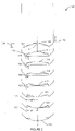
- Figure 1 illustrates a typical prior art container base profile of 211 can diameter with a 202 base size undergoing typical failure sequencing through complete reversal deformation.
- the standard progressive deterioration of the dome profile induced by excessive internal pressure is generally shown.
- the dome profile absorbs the internal pressure to a point of collapse resulting in a complete reversal of the convex domed contour.
- the reversal of the domed geometry is the defined structural failure resulting in loss of product stackability and often loss of internal pressure.
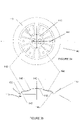
- Figure 2 illustrates a container dome profile according to the disclosure herein, wherein the novel geometric configurations of increased strength and reduced material consumption through strategic application of favorable geometric contoured shapes within the profile result in the sequential dome profile deformation.
- the geometric contoured shapes combine and merge in a complimentary mechanical system during material displacement resulting in the novel sequential dome profile deformation.
- the strategic placement of geometric contoured shapes helps generate a controlled sequential dome profile deformation which may be characterized by movement of the geometric contoured shapes in a controlled displacement resulting in a controlled and phased failure mode sequencing that is more resistant to reversal deformation.
- the unique geometric contoured shapes congruently compose a technical method of controlled sequential dome profile deformation to appreciatively increase the inner dome profile reversal strength through specific buttressing features.
- the lightweight dome profile is able to maintain its strength and structural deformation resistance, such as might be required by industry standards or a customer's request, to while utilizing lighter gauges of starting material.
- the geometric contoured shapes use the deformations of material in a complimentary manner during the focused displacement of the geometric features.
- the dome profile deformations are focused in a controlled geometric displacement by the design and shape of geometric features eliminating irregularities of force absorption.
- the novel features of the invention provide benefits during a controlled sequential dome profile deformation sequence where the geometric contoured shapes may be utilized to focus the material deformation, for example as would occur during dome failure or reversal deformation, resulting in force isolation in a complimentary manner.
- the geometric contoured shapes of the inner profile mechanically utilize the material movements and deformations improving the inner dome profile strength as well as delaying the deformation phases by delaying time of complete dome failure.
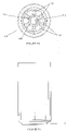
- Figure 3a-b illustrates an end-view as well as isolated cross-sectional perspective of a metallic container having a plurality of geometric contoured shapes.
- such geometric contoured shapes include panel and intertwined buttressing structures configured to generate a controlled sequential dome profile deformation as generally described herein.
- Figure 4 illustrates a perspective view of metallic container having a dome profile configured with a centrally positioned initial deformation panel coupled with a plurality of buttressing structures configured to initiate a controlled sequential dome profile deformation in one embodiment thereof.
- This figure further illustrates an exemplary deformation panel boundary, buttressing structures, and geometric panels in one embodiment thereof.
- Figure 5a illustrates a front-facing view of metallic container having a dome profile configured with a centrally positioned initial deformation panel coupled with a plurality of buttressing structures configured to initiate a controlled sequential dome profile deformation in one embodiment thereof.
- Figure 5b illustrates a side view of metallic container having an external dome profile dome profile in one embodiment thereof.
- Figure 6a illustrates a perspective view of the internal cavity of a metallic container having a dome profile configured with a centrally positioned initial deformation panel coupled with a plurality of buttressing structures configured to initiate a controlled sequential dome profile deformation in one embodiment thereof.
- Figure 6b illustrates a top view of the internal cavity of a metallic container having a dome profile configured with a centrally positioned initial deformation panel coupled with a plurality of buttressing structures configured to initiate a controlled sequential dome profile deformation in one embodiment thereof.
- Figure 7 illustrates a cross-sectional view of the internal of a metallic container having a dome profile configured with a centrally positioned initial deformation panel coupled with a plurality of buttressing structures configured to initiate a controlled sequential dome profile deformation in one embodiment thereof.
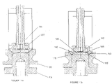
- Figure 8 illustrates a dome profile formation device and tooling arrangement that may be used to manufacture the novel dome profile in one embodiment thereof.
- Figure 9a-b illustrates a dome forming toll that may be used to manufacturer a metallic container having a dome profile configured with a centrally positioned initial deformation panel coupled with a plurality of buttressing structures configured to initiate a controlled sequential dome profile deformation in one embodiment thereof.
- the present invention includes a variety of aspects, which may be combined in different ways.
- the following descriptions are provided to list elements and describe some of the embodiments of the present invention. These elements are listed with initial embodiments, however it should be understood that they may be combined in any manner and in any number to create additional embodiments.
- the variously described examples and preferred embodiments should not be construed to limit the present invention to only the explicitly described systems, techniques, and applications. Further, this description should be understood to support and encompass descriptions and claims of all the various embodiments, systems, techniques, methods, devices, and applications with any number of the disclosed elements, with each element alone, and also with any and all various permutations and combinations of all elements in this or any subsequent application.
- a container (1) having a traditional dome profile (10), in this instance for a metal can of a standardized material volume and weight is shown.
- This traditional dome profile (10) exhibits a inner dome profile (12) that is common within the industry.
- This inner or spherical dome profile (12) includes an inward protrusion of bi-radial tangent radii, or a unified blend of tangential spherical radii.
- the inner dome profile nose (14) radius torus has consistently been sized specifically for minimum reversal strength and sprayability between .050"-. 130". Smaller inner dome profile nose (14) radii may be structurally stronger but harder to spray and more fracture prone during formation processes.
- Traditional inner dome profiles also typically include a circumferentially tangent dome wall angle I (16). This angle is traditionally between 2-10°, or 0-15° degrees of taper being tangent to inner dome profile nose (14) and the punch nose radius (15).
- the inner dome profile (12) initial inner dome reversal I (18) begins as inward pressure exceeds the domed shape structural resistance.
- the inner dome profile (12) demonstrates an inner dome reversal II (20) sequencing mode of radial deflection due to internal force centralizing concentration onto the inner domed profile (12).
- the inner dome profile (12) continues to deform reaching a full spherical radius deflection and reversal sequencing identified as inner dome reversal III (22) where the dome wall angle III (25) begins to displace inwardly.
- the inward leaning of the dome wall angle II (24) begins to collapse from A to B degrees as the profile structure folds over collapsing the traditional domed profile (10) toward a final reversal displacement failure mode.
- inner dome reversal 28
- This inner dome reversal (28) results in product failure, in-stackability.
- dome wall angle IV (26) C also identified as angle C, inwardly collapses to the point that it is unrecoverable.
- the traditional dome profile (10) reaches a stage of full structural reversal failure (30) where the dome profile exceeds profile boundaries causing complete un-stackability and final product profile structural reversal displacement failure mode.
- pulldown (32) represents the volume of metal or other material required due to dome profile depth (34). Specifically, a specific pulldown (32) is required for traditional dome profiles (10) to meet the minimum structural performance criteria.
- the amount of pulldown (32) is generally defined by the amount of container wall circumferential metal volume which is consumed by the inner dome profile (12) formation process. As can be seen in the figures, the deeper the inner dome profile (12) is formed, the more metal is consumed and the heavier the finished container or bottle will ultimately be. Inversely, as the dome depth (34) is reduced, the reversal resistance performance of the container is also reduced.
- the invention includes a novel, lightweight dome profile (100) that may be configured to include one or more geometric contoured shapes that are configured to allow the controlled sequential dome profile deformation of the dome profile (100) in response to an exerted force, such as may be generated from internal liquid pressurization, dropping the container from a height, or through pasteurization processes as generally described herein.
- a centrally positioned initial deformation panel (110) may be integrally positioned in the inner dome profile (111).
- initial deformation panel (110) may be configured to undergo a controlled sequential dome profile deformation in response to an exerted force, such as internal pressure changes in a container.
- an initial deformation panel (110) is integrally coupled with one or more geometric contoured shapes.
- an initial deformation panel (110) includes a deformation panel boundary (113) having one or more spherical radii or tangential radial segments (146, 145) that are further coupled with a plurality of buttressing structures (140), separated by alternating geometric panels extending radially outward from the initial deformation panel (110) to the inner leg (150) of the dome profile.
- these geometric contoured shapes may act synergistically to allow a controlled sequential dome profile deformation as generally described below.
- the lightweight dome profile (100) is configured to under go a controlled sequential dome profile deformation.
- reversal energy is exerted on the geometric contoured shapes of the lightweight dome profile (100) causing the displacement the coupled geometric contoured shapes or structures in a complimentary and controlled manner of primary force transference of displacement energy via work energy of the adjacent geometric structures.
- the displacement energy generates deformation forces during the container profile geometric structural movements that may result from excessive internal pressurization via various means such as fluid pressurization, gaseous pressurization, such as may be casued by a build up of carbon-dioxide or nitrogen, drop energy, growth energy in pasteurization or dome reversal displacement energy.
- a reversal energy is exerted on the initial deformation panel (110) causing it to initial a controlled sequential dome profile deformation.
- the initial deformation panel (110) in response to the application of a reversal energy begins to collapse in an initial dome reversal action.
- the preliminary movement of the initial deformation panel (110) transfers the reversal energy input outward into the adjacent buttressing structures (140). This energy transfer allows the conversion of the reversal energy into structural leverage of adjacent buttressing structures (140) via outward lateral displacement.
- the leveraged deformation strain energy passing through the buttressing structures (140) initiates lateral dome profile displacements through outward compression supporting the vertical consistency of inner dome wall angle or inner conical leg angle (118).
- This change of leveraged deformation energy enables the work of the lateral deformations in the lightweight dome profile (100) to transfer vertical force concentration laterally such that the buttressing structures (140) reinforce and thereby retain position the inner dome wall (170) maintaining the vertical orientation angle of the inner conical leg angle (118).
- this prolonged retention of the inner conical leg angle (118) prevents collapse of the angle as identified as inner conical leg angle I (120) , inner conical leg angle II (122) , inner conical leg angle III (124), and .
- the reversal energy causes the reversal deformation of the initial deformation panel (110) transfers the reversal energy input outward into the adjacent buttressing structures (140) causing further lateral leverage in the adjacent buttressing structures (140) which, in turn further reinforces and thereby retains the position the inner dome wall (170) maintaining the vertical orientation angle of the inner conical leg angle (118).
- the transfer of energy laterally into the buttressing structures (140) may lock-in the inner conical leg angle (118).
- the synergistic effect of the lightweight dome profile (100) is such that as the deformation energies continue to strengthen, the buttressing structures (140) concurrently increase their mechanical leveraged action to prevent the collapse of inner conical leg angle (118). Collapse of the inner conical leg angle (118) being an important structural failure inflection point that may result in, for example, complete dome reversal (130). The longer the inner conical leg angle (118) can be maintained, the more resistant the lightweight dome profile (100) is to the reversal energy and profile deformation movements that may result in loss of structural integrity and/or dome reversal.
- structural displacement of the initial deformation panel (110) allows energy transference to the initial deformation panel (110), (generally being shown at as sequential failure modes, shown here as initial deformation panel reversal I (114), initial deformation panel reversal II (116), and initial deformation panel reversal III (117),) to be controlled and sequential.
- the configuration of the lightweight dome profile (100) allows movement of the initial deformation panel (110) which in turn causes the buttressing structures (140) to react to the deformation energy by transferring forces outwardly with displacement to "lock in" the inner conical leg angle (118), and retain the profile structure, for example identified as initial deformation panel reversal III (117), over a prolonged and high force potential.
- the prolonged vertical orientation of the inner conical leg angle (118) over an extended time (such angles being identified at sequential failure modes by numbers 118, 120, 122, 124, 125, 126) demonstrates the primary structural improvements of the buttressing geometries displacing internal deformation energy of the inner dome profile (111) outward displacement which significantly increases dome profile total reversal performance by delaying collapse of the inner conical leg angle (identified here as number 126), resulting in significantly improved dome profile geometries resistance to deformation failure.
- the shape, placement, orientation, number, and configuration of geometric contoured shapes utilized in the lightweight dome profile (100) may be customized to be adaptable to various container sizes, materials, conditions or specification. Such characteristic may be modified to confirm to industry or customer's requirements, or container use applications, such as a need to be pasteurized or stored in a location with high ambient temperature.
- a initial deformation panel (110) may have a larger diameter, is coupled with a plurality of buttressing structures (140), which may further take a variety of forms and shapes.
- a plurality of buttressing structures (140) Such an example is non-limiting and merely provided to show the high-level of customization and adaptability in the inventions lightweight dome profile.
- the shape and size of the spherical radius of the initial deformation panel (110) in specific combination of radii (145, 146) may allow modulation of the actual and specific value of controlled structural reversal pressure of the lightweight dome profile (100).
- These initial deformation panel (110) of the lightweight dome profile (100) may be optimized through modulations in size, diameter, radii, placement and number, to deflect and deform initially, providing the energy transference of structural enhancement through buttressing outward leverage.
- the actual starting gauge of a metal, in combination of these geometric size options of initial deformation panel (110), and radii (145, 146) may produce a specified and controllable failure pressure utilized to produce the primary displacement actions providing structural energy to the remaining geometries of the lightweight dome profile 110.
- This displacement action of the initial deformation panel (110) may utilize the displacement energy of the structural deformations to increase and strengthen the lightweight dome profile (100) in sequential failure modes, generally shown here as initial deformation panel reversal I (114), initial deformation panel reversal II (116), and initial deformation panel reversal III (117), through the lateral displacement leverage of the buttressed structures supporting the inner conical leg angle (in this embodiment shown at inner conical leg angle IV (125)) of the inner dome wall (170) prior to crossing a threshold of reversal failure, which in this embodiment may be shown where the inner conical leg angle is identified at 126 and/or full structural reversal failure (30).
- This structurally reinforcing action may compliment the profile strength of any can size and any container base dome profile by enhancing the structural reversal displacements of the adjacent geometries.
- the complimentary action of this laterally deflected energy is structurally improving and strengthening geometries of the lightweight dome profile (100).
- a single initial deformation panel (110) is coupled with a plurality of buttressing structures (140).
- a single initial deformation panel (110) may be approximately positioned within the center of the inner dome profile (111) and have a radios that is approximately less than that of the container, and in some instances the inner leg (150).
- six individual buttressing structures (140) may be coordinate with the centrally positioned initial deformation panel (110).
- Such individual buttressing structures (140) may be configured to be separated by sequentially positioned geometric panels (160), and may further be configured to transmit maintain the inner dome wall or inner conical leg angle 118 at the formed angle over a longer period of force application and withstand higher levels of force resistance as described above.
- pairs of buttressing structures (140) may be positioned in opposing positions, while it other embodiment, for example as shown in figure 3 , may be positioned sequentially and equidistantly around the centrally positioned initial deformation panel (110).
- buttressing structures (140) and geometric panels (160) may be modular in nature such that they can be configured to provided the desired level force resistance based on the size of container, amount of liquid intended to be container within the container, the type and/or gauge of a starting material, as well as the softness of the allow utilized.
- a single pair of buttressing structures (140) may be configured in opposing positions coupled with a positioned initial deformation panel (110). Additional embodiments may include anywhere from 1, to a plurality buttressing structures (140) depending on the variable described above.
- initial deformation panel (110) sequentially passed through the failure modes previously described (generally identified as initial deformation panel reversal I (114)initial deformation panel reversal II (116), initial deformation panel reversal III (117),and initial deformation panel reversal IV (119), at a certain point it may reach failure mode (212) wherein it reaches a maximum displacement position.
- the inner dome profile (111) of the initial deformation panel (110) stretches the geometric contoured shapes, such as the buttressing structures (140) and the like, resulting in the failure of outward force containment of inner the conical leg angle (118) at a maximum reversal resistance performance for the starting gauge material.
- the direct concentration of high tensile leverage exerted of for example as shown in figure 1 at numbers 24, 25, 26, focuses displacements of instability inducing reversal of the inner dome profile (12).
- this localization of instability through such translated tensile energies focus concentration onto the radius at the top of the support leg or dome shoulder radius (14).
- This high concentration of energy results in unstable displacement and deformation inducing inner conical leg collapse angle 'C' generally identified as number 26.
- such the novel lightweight dome profile (100) of the present invention overcomes these early structural sequential failure accelerating sequences.
- geometric contoured shapes including a initial deformation panel (110), buttressing structures (140), geometric panel (160) and/or a deformation panel boundary (113) utilize the buttressing structures (140) and/or geometric panel (160) deformation energy in complimentary leveraged resistance utilizing displacement of elements structural geometries increasing structural resistance to the unwrapping failure mode of inherent traditional dome profile (12) designs.
- one or more buttressing geometric features (140) utilize the deformation energy initial deformation panel (110), for example as shown at number 111, to lock the displacements of the center spherical panel geometries, shown at initial deformation panel reversal modes I (114), and II (116) respectively, which results in significantly higher force structural resistance and failure resistance at a lower dome depth (134) and less starting material than traditional dome profiles (10).
- dome profiles (10) suffer from dome fracture during formation and manufacture.
- the inner leg depth induces thinning of the starting material thicknesses which is stretched and drawn around the inner domer tooling radii during formation.
- the metal shape is wrapped and stretched around the inner nose radius of the tool, while it is also clamped externally from the outer domer profile of the base geometry for stackability. Therefore, the dome shoulder radius (14) radius material is in high tensile load which increases as the depth of dome (34) increases.
- Increasing dome depth improves failure resistance, directly increases thinning of profiles, for example the dome shoulder radius (14) and punch nose radius (15), often resulting in increased fracture problems due to exceeding elastic limits of the material.
- the manufacturers of containers and bottles must also complete an inspection for fracture and crack detection within the traditional dome profile (10) geometries of all containers produced. Often these fractures are difficult to detect and may not be fully visible by the light and/or camera based detection systems. These fractures may often be sub-surface and frequently do not become visibly evident until they are pressurized and/or filled with product. The failure effects of filled containers with product may occur instantly once filled and/or pressurized or over time the failure may be delayed where failure causes greater damage of stored products and surrounding storage facilities.
- the fracture tendency and frequency of traditional dome profile (10) geometries greatly increases as the dome depth (34) is increased to meet minimum failure resistance pressure requirements of thinner more weight efficient gauges. This interaction is especially prevalent as the starting material gauge thickness becomes thinner and thinner.
- the lightweight dome profile (100) resolves these issues and reduces the fracture rates, with less metal thinning problems by directly reducing the required dome depth formation sensitivities with significantly lower tensile intensity concentrations of material stretching induced during improved dome profile formation and intrinsically reduced dome depth requirements of the initial deformation panel (110) structures, geometric panel (160) structures and buttressing formations (140) while meeting and exceeding the industry minimum dome failure structural resistance performance.
- such geometric contoured shapes integrally formed in a lightweight dome profile (100) not only eliminate the need for post-processing or reforming.
- embodiments of the lightweight dome profile (100) may allows for starting gauges below about 0.0106 inches, or lower temper and yield strength alloys below 45ksi without the need for additional post-processing or reforming.
- the invention includes a novel dome profile (1).
- the dome profile (1) may be configured to undergo an initial structural deflection sequencing as generally shown in figure 2 .
- a lightweight dome profile (11) may be manufactured using a formation devices as generally disclosed.
- the tool may include a punch sleeve (230) with a corresponding punch nose (222) and a punch bolt retainer (220) mounted onto a cyclic ram of a "bodymaker.”
- this tooling (200) may further include of an inner dome die (210) which may form the profile (212) which may also be referred to as the "dome post.”
- An outer domer die (216), also referred to as a "clamp ring” and a clamp ring retainer (214) are also demonstrated.
- aluminum or steel coil - rolled to a desired thickness may be initially established.
- a cup may be cut and drawn from the aluminum or steel coil sheet which may then be fed into a bodymaker which irons, or reduces the wall thickness.
- the cup is positioned so as to be manipulated by the stroke of a bodymaker ram.
- the initial dome structure is formed at the end of each stroke of the bodymaker.
- a set of dome tools form the dome shape while an outer domer die clamps and holds the metal taught while the ram stroke continues to form the dome.
- an inner domer which is generally spherical in shape, and stretches the inner dome portion of the base profile.
- the lightweight dome profile (110) geometries may be generated using a coining punch. This may be accomplished by using a triple action doming assembly in which the formation process may be assisted with vacuum drawing of the inner panel geometries. In combination with a coined feature defined by the "punch bolt'" to improve the initial deflection panel edges and clarify the shape outline.
- this punch bolt may create the definition of the circularity or shape of the initial panel tangential radii connecting the features to the initial deformation panel (110), buttressing structures (140), geometric panels (160) and/or a deformation panel boundary (113).
- This shaped punch bolt may be used as a coining feature to define and set the geometry properly for the desired strength and deflection/failure sequencing demonstrated in the lightweight dome profile's (100) ability to initiate a controlled sequential dome profile deformation.
- the invention's lightweight dome profile (100) varies in the method of dome depth formation by utilizing unique tooling geometries.
- the lightweight dome profile (100) may form the depth of the dome shape at much lower depths than traditional dome profiles (10). This in turn provides metal savings, by using less material.
- the added shape and definition is provided by the unique geometric contoured shapes and the profile combinations as described herein to increase dome strength.
- the term “includes” and “including” mean, but is not limited to, “includes” or “including” and “includes at least” or “including at least.”
- the term “based on” means “based on” and “based at least in part on.”
- the terms "can,” “container,” “preform” and/or “bottle” may be used interchangeably and generally include shaped, ironed or formed metallic containers.
- the term "about” or “approximately” generally refers to a range include a plus or minus value of up to a 15% variance.
Landscapes
- Engineering & Computer Science (AREA)
- Mechanical Engineering (AREA)
- Ceramic Engineering (AREA)
- Containers Having Bodies Formed In One Piece (AREA)
Claims (9)
- Verformungsbeständiger Metallbehälter, der Folgendes umfasst:- ein leichtgewichtiges Kuppelprofil (100), das an einem abschließenden Ende eines Behälters (10) positioniert ist, das konfiguriert ist, um zu einer gesteuerten sequentiellen Kuppelprofilverformung fähig zu sein, wobei das leichtgewichtige Kuppelprofil (100) Folgendes umfasst:- wenigstens eine anfängliche Verformungsplatte (110), die an einer zentralen Position auf einem inneren Kuppelprofil (111) des leichtgewichtigen Kuppelprofils (100) positioniert ist, wobei die anfängliche Verformungsplatte (110) eine nach innen erhabene kugelförmige kuppelförmige Struktur umfasst, die durch ein oder mehre tangentiale radiale Segmente (145, 146) definiert ist;- eine Verformungsplattenbegrenzung (113), die eine Umfangsbegrenzung der wenigstens einen anfänglichen Verformungsplatte (110) ausbildet;- ein Netzwerk von Stützstrukturen (140), das zwischen mehreren geometrischen Platten (160) positioniert ist, die mit der Deformationsplattenbegrenzung (113) des leichtgewichtigen Kuppelprofils gekoppelt sind; und- einen in Umfangsrichtung positionierten inneren Schenkel (150), der konfiguriert ist, um einen inneren konischen Schenkelwinkel (118) aufzuweisen, der mit dem Netzwerk von Stützstrukturen (140) und den mehreren geometrischen Platten (160) gekoppelt ist;- wobei die gesteuerte sequentielle Kuppelprofilverformung als Reaktion auf ein Aufbringen einer Verformungsenergie auf das leichtgewichtige Kuppelprofil (100) eingeleitet wird, derart, dass eine Bewegung der anfänglichen Verformungsplatte (110) die Verformungsenergie von der Verformungsplattenbegrenzung (113) nach außen auf das Netzwerk von Stützstrukturen (140) überträgt, wodurch eine Hebelverformungsverschiebungswirkung erzeugt wird, die den inneren konischen Schenkelwinkel (118) trägt, wodurch die strukturelle Integrität des leichtgewichtigen Kuppelprofils (100) verstärkt wird;- dadurch gekennzeichnet, dass die wenigstens eine anfängliche Verformungsplatte (110) mit der Verformungsplattenbegrenzung (113) einstückig gekoppelt ist, dadurch, dass das Netzwerk von Stützstrukturen (140) mit den mehreren geometrischen Platten (160) einstückig gekoppelt ist, dadurch, dass das Netzwerk von Stützstrukturen (140) und die mehreren geometrischen Platten (160) mit der wenigstens einen anfänglichen Verformungsplatte (110) an der Verformungsplattenbegrenzung (113) einstückig gekoppelt sind; und- dadurch, dass der in Umfangsrichtung positionierte innere Schenkel (150) mit dem Netzwerk von Stützstrukturen (140) und mit den mehreren geometrischen Platten (160) einstückig gekoppelt ist.
- Verformungsbeständiger Metallbehälter nach Anspruch 1, wobei die Verformungsenergie eine Verformungsenergie umfasst, die aus der Gruppe ausgewählt ist, die aus Folgendem besteht: eine Verformungsenergie, die durch flüssige und/oder gasförmige Druckbeaufschlagung des Behälters erzeugt wird; eine Verformungsenergie, die durch Pasteurisierung des Behälters erzeugt wird, Fallenergie, Kuppelumkehrverschiebungsenergie und Behälterwachstumsenergie.
- Verformungsbeständiger Metallbehälter nach Anspruch 1, wobei das Netzwerk von Stützstrukturen mehrere gegenüberliegende Stützstrukturen umfasst, die zwischen den mehreren geometrischen Platten positioniert sind.
- Verformungsbeständiger Metallbehälter nach Anspruch 1, wobei der innere konische Schenkelwinkel einen inneren konischen Schenkelwinkel umfasst, der aus der Gruppe ausgewählt ist, die aus Folgendem besteht: einem inneren konischen Schenkelwinkel, der einen Verjüngungsgrad von 2-10° aufweist und/oder einem inneren konischen Schenkelwinkel, der einen Verjüngungsgrad von 0-15° aufweist.
- Leichtgewichtiges Kuppelprofil (100) aus Metall, das Folgendes umfasst:- wenigstens eine anfängliche Verformungsplatte (110), die auf einem inneren Kuppelprofil (111) eines Behälters (10) positioniert ist, wobei die wenigstens eine anfängliche Verformungsplatte (110) eine nach innen erhabene kugelförmige kuppelförmige Struktur umfasst, die mit einer Verformungsplattenbegrenzung (113) gekoppelt ist, die eine Umfangsbegrenzung der anfänglichen Verformungsplatte (110) ausbildet, wenigstens eine geometrisch konturierte Form (140, 160), wobei die wenigstens eine anfängliche Verformungsplatte (110) mit wenigstens einer geometrischen konturierten Form (140, 160) an der Deformationsplattenbegrenzung (113) gekoppelt ist, einen in Umfangsrichtung positionierten inneren Schenkel (150), der konfiguriert ist, um einen inneren konischen Schenkelwinkel (118) aufzuweisen, der mit der wenigstens einen geometrischen konturierten Form (140, 160) gekoppelt ist, wobei die wenigstens eine geometrisch konturierte Form (140, 160) konfiguriert ist, um, als Reaktion auf eine Verformungsenergie, zu der Einleitung einer gesteuerten sequentiellen Kuppelprofilverformung fähig zu sein;- wobei die Bewegung der anfänglichen Verformungsplatte (110) die Verformungsenergie auf die wenigstens eine geometrische konturierte Form (140, 160) überträgt, wodurch eine Hebelverformungsverschiebungswirkung erzeugt wird, die den inneren konischen Schenkelwinkel des leichtgewichtigen Kuppelprofils trägt;- dadurch gekennzeichnet, dass die wenigstens eine anfängliche Verformungsplatte (110) mit der Verformungsplattenbegrenzung (113) einstückig gekoppelt ist, dadurch, dass die wenigstens eine geometrische konturierte Form (140, 160) mit der wenigstens einen anfänglichen Verformungsplatte (110) an der Verformungsplattenbegrenzung (113) einstückig gekoppelt ist und dadurch, dass der in Umfangsrichtung positionierte innere Schenkel (150) mit der wenigstens einen geometrischen konturierten Form (140, 160) einstückig gekoppelt ist.
- Leichtgewichtiges Kuppelprofil aus Metall nach Anspruch 5, wobei die nach innen erhabene kugelförmige kuppelförmige Struktur durch wenigstens einen kugelförmigen Radius definiert ist.
- Leichtgewichtiges Kuppelprofil aus Metall nach Anspruch 5, wobei die wenigstens eine geometrisch konturierte Form eine oder mehrere Stützstrukturen (140) und eine oder mehrere geometrische Platten (160) umfasst, die mit der wenigstens einen anfänglichen Verformungsplatte gekoppelt sind.
- Leichtgewichtiges Kuppelprofil aus Metall nach Anspruch 7, wobei die gesteuerte sequentielle Kuppelprofilverformung als Reaktion auf das Aufbringen einer Verformungsenergie auf das leichtgewichtige Kuppelprofil eingeleitet wird, derart, dass die Bewegung der wenigstens einen anfänglichen Verformungsplatte die Verformungsenergie nach außen auf die eine oder die mehreren Stützstrukturen überträgt, wodurch eine Hebelverformungsverschiebungswirkung erzeugt wird, die den inneren konischen Schenkelwinkel trägt, wodurch die strukturelle Integrität des leichtgewichtigen Kuppelprofils verstärkt wird.
- Leichtgewichtiges Kuppelprofil aus Metall nach Anspruch 5, wobei der innere konische Schenkelwinkel einen inneren konischen Schenkelwinkel umfasst, der aus der Gruppe ausgewählt ist, die aus einem inneren konischen Schenkelwinkel, der einen Verjüngungsgrad von 2-10° aufweist, und/oder einem inneren konischen Schenkelwinkel, der einen Verjüngungsgrad von 0-15° aufweist, besteht.
Applications Claiming Priority (2)
| Application Number | Priority Date | Filing Date | Title |
|---|---|---|---|
| US201762488125P | 2017-04-21 | 2017-04-21 | |
| PCT/US2018/028751 WO2018195525A1 (en) | 2017-04-21 | 2018-04-21 | Dome formation profile & method of lightweight container design and manufacture |
Publications (3)
| Publication Number | Publication Date |
|---|---|
| EP3612467A1 EP3612467A1 (de) | 2020-02-26 |
| EP3612467A4 EP3612467A4 (de) | 2021-02-17 |
| EP3612467B1 true EP3612467B1 (de) | 2022-05-25 |
Family
ID=63857029
Family Applications (1)
| Application Number | Title | Priority Date | Filing Date |
|---|---|---|---|
| EP18787745.1A Active EP3612467B1 (de) | 2017-04-21 | 2018-04-21 | Behälter mit verformungsfestem kuppelboden |
Country Status (10)
| Country | Link |
|---|---|
| US (2) | US10435224B2 (de) |
| EP (1) | EP3612467B1 (de) |
| JP (1) | JP2020517548A (de) |
| CN (1) | CN110891875A (de) |
| AU (1) | AU2018254774A1 (de) |
| BR (1) | BR112019022069A2 (de) |
| CA (1) | CA3060098A1 (de) |
| RU (1) | RU2019137481A (de) |
| WO (1) | WO2018195525A1 (de) |
| ZA (1) | ZA201907583B (de) |
Families Citing this family (2)
| Publication number | Priority date | Publication date | Assignee | Title |
|---|---|---|---|---|
| US12129072B2 (en) | 2021-11-30 | 2024-10-29 | Pepsico, Inc. | Flexible base for aseptic-fill bottles |
| FR3165871A1 (fr) * | 2024-09-04 | 2026-03-06 | Sidel Participations | Récipient ayant un fond renforcé et fond de moule pour la fabrication d’un tel récipient |
Family Cites Families (34)
| Publication number | Priority date | Publication date | Assignee | Title |
|---|---|---|---|---|
| US77280A (en) * | 1868-04-28 | John l | ||
| US204971A (en) * | 1878-06-18 | Improvement in bottoms for cotton-cans | ||
| US3905507A (en) | 1974-04-05 | 1975-09-16 | Nat Can Corp | Profiled bottom wall for containers |
| US3979009A (en) | 1975-03-21 | 1976-09-07 | Kaiser Aluminum & Chemical Corporation | Container bottom structure |
| US4120419A (en) * | 1976-02-23 | 1978-10-17 | National Steel Corporation | High strength seamless chime can body, sheet metal container for vacuum packs, and manufacture |
| JPS5325186A (en) * | 1976-08-20 | 1978-03-08 | Daiwa Can Co Ltd | Metallic can for drink containing carbon dioxide or the like |
| US4108324A (en) * | 1977-05-23 | 1978-08-22 | The Continental Group, Inc. | Ribbed bottom structure for plastic container |
| US4732292A (en) * | 1978-06-16 | 1988-03-22 | Schmalbach-Lubeca Gmbh | Flexible bottom profile for drawn and ironed beverage can |
| JPS6076613U (ja) * | 1983-10-31 | 1985-05-29 | 日精エー・エス・ビー機械株式会社 | 耐熱性合成樹脂びん |
| US4953738A (en) * | 1988-02-19 | 1990-09-04 | Stirbis James S | One piece can body with domed bottom |
| US4909393A (en) * | 1988-11-14 | 1990-03-20 | Berwick Container Corp. | Container reconfiguring system |
| US5836473A (en) * | 1990-04-06 | 1998-11-17 | Ball Corporation | Beverage container with increased bottom strength |
| US5119962A (en) * | 1990-10-12 | 1992-06-09 | Continental White Cap, Inc. | Closure button/panel energy enhancement |
| GB9216247D0 (en) * | 1992-07-30 | 1992-09-09 | Cmb Foodcan Plc | Souffle:can ends |
| US5680952A (en) * | 1994-09-12 | 1997-10-28 | Ball Corporation | End constructions for containers |
| EP0778224A1 (de) * | 1995-12-05 | 1997-06-11 | Alusuisse Technology & Management AG | Gasdichter Behälter |
| US5626228A (en) * | 1996-05-01 | 1997-05-06 | Anheuser-Busch Incorporated | Thin-walled can having plurality of supporting feet with two support features |
| DE19708826C3 (de) * | 1996-12-01 | 2003-10-30 | Hans Werner Franzer | Behälter, insbesondere Dose, aus dünnwandigem Blech |
| DE69919375T2 (de) | 1998-06-03 | 2005-02-24 | CROWN Packaging Technology, Inc, Alsip | Dosenboden mit erhöhter Druckfestigkeit und Vorrichtung zur Herstellung desselben |
| US6296139B1 (en) | 1999-11-22 | 2001-10-02 | Mitsubishi Materials Corporation | Can manufacturing apparatus, can manufacturing method, and can |
| US6293422B1 (en) * | 2000-03-08 | 2001-09-25 | Ball Corporation | Container with combination convex/concave bottom |
| US6634517B2 (en) * | 2001-09-17 | 2003-10-21 | Crown Cork & Seal Technologies Corporation | Base for plastic container |
| US6736284B2 (en) * | 2001-10-16 | 2004-05-18 | Elmer D. Werth | End closure structure and method and container having reinforcing rib structures |
| EP1332971A1 (de) | 2002-02-05 | 2003-08-06 | Corus Staal BV | Bodenkontur mit einer Kuppel für einen Druckbehälter |
| US20040000533A1 (en) * | 2002-07-01 | 2004-01-01 | Satya Kamineni | Pressurizable container |
| US9751679B2 (en) * | 2003-05-23 | 2017-09-05 | Amcor Limited | Vacuum absorbing bases for hot-fill containers |
| US7472800B2 (en) | 2004-03-05 | 2009-01-06 | Rexam Beverage Can Company | Bottom profile for drawn and ironed can body |
| US7732035B2 (en) * | 2006-03-07 | 2010-06-08 | Plastipak Packaging, Inc. | Base for plastic container |
| US20080029523A1 (en) * | 2006-08-04 | 2008-02-07 | Rexam Beverage Can Co. | Metal/plastic containers with reinforcing ribs and drawing and ironing |
| FR2932458B1 (fr) * | 2008-06-13 | 2010-08-20 | Sidel Participations | Recipient, notamment bouteille, en matiere thermoplastique equipe d'un fond renforce |
| JP5256155B2 (ja) * | 2009-09-24 | 2013-08-07 | 麒麟麦酒株式会社 | 有底筒状体形状の缶容器本体およびそれに飲料を充填した飲料缶製品 |
| US8444002B2 (en) * | 2010-02-19 | 2013-05-21 | Graham Packaging Lc, L.P. | Pressure compensating bases for polymeric containers |
| JP6761159B2 (ja) * | 2014-11-19 | 2020-09-23 | キョーラク株式会社 | 積層剥離容器 |
| US10053275B2 (en) * | 2014-12-22 | 2018-08-21 | Graham Packaging Company, L.P. | Deformation-resistant container with panel indentations |
-
2018
- 2018-04-21 EP EP18787745.1A patent/EP3612467B1/de active Active
- 2018-04-21 WO PCT/US2018/028751 patent/WO2018195525A1/en not_active Ceased
- 2018-04-21 AU AU2018254774A patent/AU2018254774A1/en not_active Abandoned
- 2018-04-21 BR BR112019022069A patent/BR112019022069A2/pt not_active Application Discontinuation
- 2018-04-21 JP JP2020507508A patent/JP2020517548A/ja active Pending
- 2018-04-21 CA CA3060098A patent/CA3060098A1/en not_active Abandoned
- 2018-04-21 RU RU2019137481A patent/RU2019137481A/ru unknown
- 2018-04-21 CN CN201880026380.2A patent/CN110891875A/zh active Pending
- 2018-05-21 US US15/985,420 patent/US10435224B2/en active Active
-
2019
- 2019-10-07 US US16/594,969 patent/US11167906B2/en not_active Expired - Fee Related
- 2019-11-15 ZA ZA2019/07583A patent/ZA201907583B/en unknown
Also Published As
| Publication number | Publication date |
|---|---|
| US10435224B2 (en) | 2019-10-08 |
| US20190055074A1 (en) | 2019-02-21 |
| CA3060098A1 (en) | 2018-10-25 |
| RU2019137481A (ru) | 2021-05-21 |
| JP2020517548A (ja) | 2020-06-18 |
| CN110891875A (zh) | 2020-03-17 |
| ZA201907583B (en) | 2020-09-30 |
| AU2018254774A1 (en) | 2019-12-12 |
| BR112019022069A2 (pt) | 2020-05-05 |
| WO2018195525A1 (en) | 2018-10-25 |
| US20200031554A1 (en) | 2020-01-30 |
| US11167906B2 (en) | 2021-11-09 |
| EP3612467A4 (de) | 2021-02-17 |
| EP3612467A1 (de) | 2020-02-26 |
Similar Documents
| Publication | Publication Date | Title |
|---|---|---|
| US11738382B2 (en) | Shaped metal container, microstructure, a method for making a shaped metal container | |
| US6460723B2 (en) | Metallic beverage can end | |
| US8235244B2 (en) | Container end closure with arcuate shaped chuck wall | |
| US6131761A (en) | Can bottom having improved strength and apparatus for making same | |
| US5421480A (en) | Thin-walled can having a displaceable bottom | |
| KR101386770B1 (ko) | 깡통용 깡통단부 및 이를 구비한 깡통 | |
| JP5952804B2 (ja) | 缶の製造 | |
| JPH04502445A (ja) | 容器 | |
| EP3919200B1 (de) | Nahtloser dosenkörper und verfahren zur herstellung eines nahtlosen dosenkörpers | |
| JP2014531371A (ja) | 縮小ゲージ王冠およびその作成方法 | |
| US10661937B2 (en) | Container provided with a curved invertible diaphragm | |
| EP3612467B1 (de) | Behälter mit verformungsfestem kuppelboden | |
| JP7670051B2 (ja) | 缶容器及びその製造方法 | |
| US20110011896A1 (en) | Steel one-piece necked-in aerosol can | |
| US20020139805A1 (en) | Beverage can end with reduced countersink | |
| JP2003128060A (ja) | 変形シームレス缶およびその製造方法 | |
| WO2008018942A2 (en) | Metal/plastic containers with reinforcing ribs and drawing and ironing | |
| US20140197181A1 (en) | Three-piece can | |
| US20090272750A1 (en) | Container bottom | |
| AU2002236856A1 (en) | Metallic beverage can end | |
| WO2011154800A1 (en) | Packaging | |
| US20130098905A1 (en) | Three-piece can | |
| KR20040059946A (ko) | 내압강도가 우수한 경량 스틸 2 피스 디앤아이 캔 제조방법 |
Legal Events
| Date | Code | Title | Description |
|---|---|---|---|
| STAA | Information on the status of an ep patent application or granted ep patent |
Free format text: STATUS: THE INTERNATIONAL PUBLICATION HAS BEEN MADE |
|
| PUAI | Public reference made under article 153(3) epc to a published international application that has entered the european phase |
Free format text: ORIGINAL CODE: 0009012 |
|
| STAA | Information on the status of an ep patent application or granted ep patent |
Free format text: STATUS: REQUEST FOR EXAMINATION WAS MADE |
|
| 17P | Request for examination filed |
Effective date: 20191007 |
|
| AK | Designated contracting states |
Kind code of ref document: A1 Designated state(s): AL AT BE BG CH CY CZ DE DK EE ES FI FR GB GR HR HU IE IS IT LI LT LU LV MC MK MT NL NO PL PT RO RS SE SI SK SM TR |
|
| AX | Request for extension of the european patent |
Extension state: BA ME |
|
| DAV | Request for validation of the european patent (deleted) | ||
| DAX | Request for extension of the european patent (deleted) | ||
| A4 | Supplementary search report drawn up and despatched |
Effective date: 20210115 |
|
| RIC1 | Information provided on ipc code assigned before grant |
Ipc: B65D 1/02 20060101ALI20210111BHEP Ipc: B65D 17/00 20060101ALI20210111BHEP Ipc: B65D 79/00 20060101AFI20210111BHEP Ipc: B65D 1/42 20060101ALI20210111BHEP Ipc: B65D 1/16 20060101ALI20210111BHEP |
|
| GRAP | Despatch of communication of intention to grant a patent |
Free format text: ORIGINAL CODE: EPIDOSNIGR1 |
|
| STAA | Information on the status of an ep patent application or granted ep patent |
Free format text: STATUS: GRANT OF PATENT IS INTENDED |
|
| INTG | Intention to grant announced |
Effective date: 20211207 |
|
| GRAS | Grant fee paid |
Free format text: ORIGINAL CODE: EPIDOSNIGR3 |
|
| GRAA | (expected) grant |
Free format text: ORIGINAL CODE: 0009210 |
|
| STAA | Information on the status of an ep patent application or granted ep patent |
Free format text: STATUS: THE PATENT HAS BEEN GRANTED |
|
| AK | Designated contracting states |
Kind code of ref document: B1 Designated state(s): AL AT BE BG CH CY CZ DE DK EE ES FI FR GB GR HR HU IE IS IT LI LT LU LV MC MK MT NL NO PL PT RO RS SE SI SK SM TR |
|
| REG | Reference to a national code |
Ref country code: GB Ref legal event code: FG4D |
|
| REG | Reference to a national code |
Ref country code: CH Ref legal event code: EP |
|
| REG | Reference to a national code |
Ref country code: AT Ref legal event code: REF Ref document number: 1494178 Country of ref document: AT Kind code of ref document: T Effective date: 20220615 Ref country code: DE Ref legal event code: R096 Ref document number: 602018036016 Country of ref document: DE |
|
| REG | Reference to a national code |
Ref country code: IE Ref legal event code: FG4D |
|
| REG | Reference to a national code |
Ref country code: NL Ref legal event code: FP |
|
| REG | Reference to a national code |
Ref country code: LT Ref legal event code: MG9D |
|
| REG | Reference to a national code |
Ref country code: AT Ref legal event code: MK05 Ref document number: 1494178 Country of ref document: AT Kind code of ref document: T Effective date: 20220525 |
|
| PG25 | Lapsed in a contracting state [announced via postgrant information from national office to epo] |
Ref country code: SE Free format text: LAPSE BECAUSE OF FAILURE TO SUBMIT A TRANSLATION OF THE DESCRIPTION OR TO PAY THE FEE WITHIN THE PRESCRIBED TIME-LIMIT Effective date: 20220525 Ref country code: PT Free format text: LAPSE BECAUSE OF FAILURE TO SUBMIT A TRANSLATION OF THE DESCRIPTION OR TO PAY THE FEE WITHIN THE PRESCRIBED TIME-LIMIT Effective date: 20220926 Ref country code: NO Free format text: LAPSE BECAUSE OF FAILURE TO SUBMIT A TRANSLATION OF THE DESCRIPTION OR TO PAY THE FEE WITHIN THE PRESCRIBED TIME-LIMIT Effective date: 20220825 Ref country code: LT Free format text: LAPSE BECAUSE OF FAILURE TO SUBMIT A TRANSLATION OF THE DESCRIPTION OR TO PAY THE FEE WITHIN THE PRESCRIBED TIME-LIMIT Effective date: 20220525 Ref country code: HR Free format text: LAPSE BECAUSE OF FAILURE TO SUBMIT A TRANSLATION OF THE DESCRIPTION OR TO PAY THE FEE WITHIN THE PRESCRIBED TIME-LIMIT Effective date: 20220525 Ref country code: GR Free format text: LAPSE BECAUSE OF FAILURE TO SUBMIT A TRANSLATION OF THE DESCRIPTION OR TO PAY THE FEE WITHIN THE PRESCRIBED TIME-LIMIT Effective date: 20220826 Ref country code: FI Free format text: LAPSE BECAUSE OF FAILURE TO SUBMIT A TRANSLATION OF THE DESCRIPTION OR TO PAY THE FEE WITHIN THE PRESCRIBED TIME-LIMIT Effective date: 20220525 Ref country code: ES Free format text: LAPSE BECAUSE OF FAILURE TO SUBMIT A TRANSLATION OF THE DESCRIPTION OR TO PAY THE FEE WITHIN THE PRESCRIBED TIME-LIMIT Effective date: 20220525 Ref country code: BG Free format text: LAPSE BECAUSE OF FAILURE TO SUBMIT A TRANSLATION OF THE DESCRIPTION OR TO PAY THE FEE WITHIN THE PRESCRIBED TIME-LIMIT Effective date: 20220825 Ref country code: AT Free format text: LAPSE BECAUSE OF FAILURE TO SUBMIT A TRANSLATION OF THE DESCRIPTION OR TO PAY THE FEE WITHIN THE PRESCRIBED TIME-LIMIT Effective date: 20220525 |
|
| PG25 | Lapsed in a contracting state [announced via postgrant information from national office to epo] |
Ref country code: RS Free format text: LAPSE BECAUSE OF FAILURE TO SUBMIT A TRANSLATION OF THE DESCRIPTION OR TO PAY THE FEE WITHIN THE PRESCRIBED TIME-LIMIT Effective date: 20220525 Ref country code: PL Free format text: LAPSE BECAUSE OF FAILURE TO SUBMIT A TRANSLATION OF THE DESCRIPTION OR TO PAY THE FEE WITHIN THE PRESCRIBED TIME-LIMIT Effective date: 20220525 Ref country code: LV Free format text: LAPSE BECAUSE OF FAILURE TO SUBMIT A TRANSLATION OF THE DESCRIPTION OR TO PAY THE FEE WITHIN THE PRESCRIBED TIME-LIMIT Effective date: 20220525 Ref country code: IS Free format text: LAPSE BECAUSE OF FAILURE TO SUBMIT A TRANSLATION OF THE DESCRIPTION OR TO PAY THE FEE WITHIN THE PRESCRIBED TIME-LIMIT Effective date: 20220925 |
|
| PG25 | Lapsed in a contracting state [announced via postgrant information from national office to epo] |
Ref country code: SM Free format text: LAPSE BECAUSE OF FAILURE TO SUBMIT A TRANSLATION OF THE DESCRIPTION OR TO PAY THE FEE WITHIN THE PRESCRIBED TIME-LIMIT Effective date: 20220525 Ref country code: SK Free format text: LAPSE BECAUSE OF FAILURE TO SUBMIT A TRANSLATION OF THE DESCRIPTION OR TO PAY THE FEE WITHIN THE PRESCRIBED TIME-LIMIT Effective date: 20220525 Ref country code: RO Free format text: LAPSE BECAUSE OF FAILURE TO SUBMIT A TRANSLATION OF THE DESCRIPTION OR TO PAY THE FEE WITHIN THE PRESCRIBED TIME-LIMIT Effective date: 20220525 Ref country code: EE Free format text: LAPSE BECAUSE OF FAILURE TO SUBMIT A TRANSLATION OF THE DESCRIPTION OR TO PAY THE FEE WITHIN THE PRESCRIBED TIME-LIMIT Effective date: 20220525 Ref country code: DK Free format text: LAPSE BECAUSE OF FAILURE TO SUBMIT A TRANSLATION OF THE DESCRIPTION OR TO PAY THE FEE WITHIN THE PRESCRIBED TIME-LIMIT Effective date: 20220525 Ref country code: CZ Free format text: LAPSE BECAUSE OF FAILURE TO SUBMIT A TRANSLATION OF THE DESCRIPTION OR TO PAY THE FEE WITHIN THE PRESCRIBED TIME-LIMIT Effective date: 20220525 |
|
| REG | Reference to a national code |
Ref country code: DE Ref legal event code: R097 Ref document number: 602018036016 Country of ref document: DE |
|
| PG25 | Lapsed in a contracting state [announced via postgrant information from national office to epo] |
Ref country code: AL Free format text: LAPSE BECAUSE OF FAILURE TO SUBMIT A TRANSLATION OF THE DESCRIPTION OR TO PAY THE FEE WITHIN THE PRESCRIBED TIME-LIMIT Effective date: 20220525 |
|
| PLBE | No opposition filed within time limit |
Free format text: ORIGINAL CODE: 0009261 |
|
| STAA | Information on the status of an ep patent application or granted ep patent |
Free format text: STATUS: NO OPPOSITION FILED WITHIN TIME LIMIT |
|
| 26N | No opposition filed |
Effective date: 20230228 |
|
| PG25 | Lapsed in a contracting state [announced via postgrant information from national office to epo] |
Ref country code: SI Free format text: LAPSE BECAUSE OF FAILURE TO SUBMIT A TRANSLATION OF THE DESCRIPTION OR TO PAY THE FEE WITHIN THE PRESCRIBED TIME-LIMIT Effective date: 20220525 |
|
| REG | Reference to a national code |
Ref country code: CH Ref legal event code: PL |
|
| PG25 | Lapsed in a contracting state [announced via postgrant information from national office to epo] |
Ref country code: LU Free format text: LAPSE BECAUSE OF NON-PAYMENT OF DUE FEES Effective date: 20230421 |
|
| REG | Reference to a national code |
Ref country code: BE Ref legal event code: MM Effective date: 20230430 |
|
| PG25 | Lapsed in a contracting state [announced via postgrant information from national office to epo] |
Ref country code: MC Free format text: LAPSE BECAUSE OF FAILURE TO SUBMIT A TRANSLATION OF THE DESCRIPTION OR TO PAY THE FEE WITHIN THE PRESCRIBED TIME-LIMIT Effective date: 20220525 |
|
| PG25 | Lapsed in a contracting state [announced via postgrant information from national office to epo] |
Ref country code: MC Free format text: LAPSE BECAUSE OF FAILURE TO SUBMIT A TRANSLATION OF THE DESCRIPTION OR TO PAY THE FEE WITHIN THE PRESCRIBED TIME-LIMIT Effective date: 20220525 Ref country code: LI Free format text: LAPSE BECAUSE OF NON-PAYMENT OF DUE FEES Effective date: 20230430 Ref country code: IT Free format text: LAPSE BECAUSE OF FAILURE TO SUBMIT A TRANSLATION OF THE DESCRIPTION OR TO PAY THE FEE WITHIN THE PRESCRIBED TIME-LIMIT Effective date: 20220525 Ref country code: CH Free format text: LAPSE BECAUSE OF NON-PAYMENT OF DUE FEES Effective date: 20230430 |
|
| REG | Reference to a national code |
Ref country code: IE Ref legal event code: MM4A |
|
| PG25 | Lapsed in a contracting state [announced via postgrant information from national office to epo] |
Ref country code: BE Free format text: LAPSE BECAUSE OF NON-PAYMENT OF DUE FEES Effective date: 20230430 |
|
| REG | Reference to a national code |
Ref country code: GB Ref legal event code: 732E Free format text: REGISTERED BETWEEN 20240215 AND 20240221 |
|
| PG25 | Lapsed in a contracting state [announced via postgrant information from national office to epo] |
Ref country code: IE Free format text: LAPSE BECAUSE OF NON-PAYMENT OF DUE FEES Effective date: 20230421 |
|
| PG25 | Lapsed in a contracting state [announced via postgrant information from national office to epo] |
Ref country code: IE Free format text: LAPSE BECAUSE OF NON-PAYMENT OF DUE FEES Effective date: 20230421 |
|
| PGFP | Annual fee paid to national office [announced via postgrant information from national office to epo] |
Ref country code: NL Payment date: 20240426 Year of fee payment: 7 |
|
| PGFP | Annual fee paid to national office [announced via postgrant information from national office to epo] |
Ref country code: GB Payment date: 20240419 Year of fee payment: 7 |
|
| PGFP | Annual fee paid to national office [announced via postgrant information from national office to epo] |
Ref country code: DE Payment date: 20240423 Year of fee payment: 7 |
|
| PGFP | Annual fee paid to national office [announced via postgrant information from national office to epo] |
Ref country code: FR Payment date: 20240422 Year of fee payment: 7 |
|
| PG25 | Lapsed in a contracting state [announced via postgrant information from national office to epo] |
Ref country code: BG Free format text: LAPSE BECAUSE OF FAILURE TO SUBMIT A TRANSLATION OF THE DESCRIPTION OR TO PAY THE FEE WITHIN THE PRESCRIBED TIME-LIMIT Effective date: 20220525 |
|
| PG25 | Lapsed in a contracting state [announced via postgrant information from national office to epo] |
Ref country code: BG Free format text: LAPSE BECAUSE OF FAILURE TO SUBMIT A TRANSLATION OF THE DESCRIPTION OR TO PAY THE FEE WITHIN THE PRESCRIBED TIME-LIMIT Effective date: 20220525 |
|
| PG25 | Lapsed in a contracting state [announced via postgrant information from national office to epo] |
Ref country code: CY Free format text: LAPSE BECAUSE OF FAILURE TO SUBMIT A TRANSLATION OF THE DESCRIPTION OR TO PAY THE FEE WITHIN THE PRESCRIBED TIME-LIMIT; INVALID AB INITIO Effective date: 20180421 |
|
| PG25 | Lapsed in a contracting state [announced via postgrant information from national office to epo] |
Ref country code: HU Free format text: LAPSE BECAUSE OF FAILURE TO SUBMIT A TRANSLATION OF THE DESCRIPTION OR TO PAY THE FEE WITHIN THE PRESCRIBED TIME-LIMIT; INVALID AB INITIO Effective date: 20180421 |
|
| REG | Reference to a national code |
Ref country code: DE Ref legal event code: R119 Ref document number: 602018036016 Country of ref document: DE |
|
| REG | Reference to a national code |
Ref country code: NL Ref legal event code: MM Effective date: 20250501 |
|
| PG25 | Lapsed in a contracting state [announced via postgrant information from national office to epo] |
Ref country code: TR Free format text: LAPSE BECAUSE OF FAILURE TO SUBMIT A TRANSLATION OF THE DESCRIPTION OR TO PAY THE FEE WITHIN THE PRESCRIBED TIME-LIMIT Effective date: 20220525 |
|
| GBPC | Gb: european patent ceased through non-payment of renewal fee |
Effective date: 20250421 |
|
| PG25 | Lapsed in a contracting state [announced via postgrant information from national office to epo] |
Ref country code: DE Free format text: LAPSE BECAUSE OF NON-PAYMENT OF DUE FEES Effective date: 20251104 |
|
| PG25 | Lapsed in a contracting state [announced via postgrant information from national office to epo] |
Ref country code: GB Free format text: LAPSE BECAUSE OF NON-PAYMENT OF DUE FEES Effective date: 20250421 |
|
| PG25 | Lapsed in a contracting state [announced via postgrant information from national office to epo] |
Ref country code: FR Free format text: LAPSE BECAUSE OF NON-PAYMENT OF DUE FEES Effective date: 20250430 Ref country code: NL Free format text: LAPSE BECAUSE OF NON-PAYMENT OF DUE FEES Effective date: 20250501 |