EP3612409B1 - Antriebsmodul und lineartransportsystem - Google Patents
Antriebsmodul und lineartransportsystem Download PDFInfo
- Publication number
- EP3612409B1 EP3612409B1 EP18719519.3A EP18719519A EP3612409B1 EP 3612409 B1 EP3612409 B1 EP 3612409B1 EP 18719519 A EP18719519 A EP 18719519A EP 3612409 B1 EP3612409 B1 EP 3612409B1
- Authority
- EP
- European Patent Office
- Prior art keywords
- housing
- coil
- drive module
- housing shell
- receptacle
- Prior art date
- Legal status (The legal status is an assumption and is not a legal conclusion. Google has not performed a legal analysis and makes no representation as to the accuracy of the status listed.)
- Active
Links
Images







Classifications
-
- B—PERFORMING OPERATIONS; TRANSPORTING
- B60—VEHICLES IN GENERAL
- B60L—PROPULSION OF ELECTRICALLY-PROPELLED VEHICLES; SUPPLYING ELECTRIC POWER FOR AUXILIARY EQUIPMENT OF ELECTRICALLY-PROPELLED VEHICLES; ELECTRODYNAMIC BRAKE SYSTEMS FOR VEHICLES IN GENERAL; MAGNETIC SUSPENSION OR LEVITATION FOR VEHICLES; MONITORING OPERATING VARIABLES OF ELECTRICALLY-PROPELLED VEHICLES; ELECTRIC SAFETY DEVICES FOR ELECTRICALLY-PROPELLED VEHICLES
- B60L13/00—Electric propulsion for monorail vehicles, suspension vehicles or rack railways; Magnetic suspension or levitation for vehicles
- B60L13/03—Electric propulsion by linear motors
-
- B—PERFORMING OPERATIONS; TRANSPORTING
- B65—CONVEYING; PACKING; STORING; HANDLING THIN OR FILAMENTARY MATERIAL
- B65G—TRANSPORT OR STORAGE DEVICES, e.g. CONVEYORS FOR LOADING OR TIPPING, SHOP CONVEYOR SYSTEMS OR PNEUMATIC TUBE CONVEYORS
- B65G23/00—Driving gear for endless conveyors; Belt- or chain-tensioning arrangements
- B65G23/22—Arrangements or mountings of driving motors
-
- B—PERFORMING OPERATIONS; TRANSPORTING
- B65—CONVEYING; PACKING; STORING; HANDLING THIN OR FILAMENTARY MATERIAL
- B65G—TRANSPORT OR STORAGE DEVICES, e.g. CONVEYORS FOR LOADING OR TIPPING, SHOP CONVEYOR SYSTEMS OR PNEUMATIC TUBE CONVEYORS
- B65G23/00—Driving gear for endless conveyors; Belt- or chain-tensioning arrangements
- B65G23/24—Gearing between driving motor and belt- or chain-engaging elements
-
- B—PERFORMING OPERATIONS; TRANSPORTING
- B65—CONVEYING; PACKING; STORING; HANDLING THIN OR FILAMENTARY MATERIAL
- B65G—TRANSPORT OR STORAGE DEVICES, e.g. CONVEYORS FOR LOADING OR TIPPING, SHOP CONVEYOR SYSTEMS OR PNEUMATIC TUBE CONVEYORS
- B65G45/00—Lubricating, cleaning, or clearing devices
-
- B—PERFORMING OPERATIONS; TRANSPORTING
- B65—CONVEYING; PACKING; STORING; HANDLING THIN OR FILAMENTARY MATERIAL
- B65G—TRANSPORT OR STORAGE DEVICES, e.g. CONVEYORS FOR LOADING OR TIPPING, SHOP CONVEYOR SYSTEMS OR PNEUMATIC TUBE CONVEYORS
- B65G54/00—Non-mechanical conveyors not otherwise provided for
- B65G54/02—Non-mechanical conveyors not otherwise provided for electrostatic, electric, or magnetic
-
- H—ELECTRICITY
- H02—GENERATION; CONVERSION OR DISTRIBUTION OF ELECTRIC POWER
- H02K—DYNAMO-ELECTRIC MACHINES
- H02K5/00—Casings; Enclosures; Supports
- H02K5/04—Casings or enclosures characterised by the shape, form or construction thereof
-
- B—PERFORMING OPERATIONS; TRANSPORTING
- B65—CONVEYING; PACKING; STORING; HANDLING THIN OR FILAMENTARY MATERIAL
- B65B—MACHINES, APPARATUS OR DEVICES FOR, OR METHODS OF, PACKAGING ARTICLES OR MATERIALS; UNPACKING
- B65B35/00—Supplying, feeding, arranging or orientating articles to be packaged
- B65B35/10—Feeding, e.g. conveying, single articles
- B65B35/24—Feeding, e.g. conveying, single articles by endless belts or chains
-
- B—PERFORMING OPERATIONS; TRANSPORTING
- B65—CONVEYING; PACKING; STORING; HANDLING THIN OR FILAMENTARY MATERIAL
- B65G—TRANSPORT OR STORAGE DEVICES, e.g. CONVEYORS FOR LOADING OR TIPPING, SHOP CONVEYOR SYSTEMS OR PNEUMATIC TUBE CONVEYORS
- B65G2207/00—Indexing codes relating to constructional details, configuration and additional features of a handling device, e.g. Conveyors
- B65G2207/26—Hygienic features, e.g. easy to sanitize
-
- H—ELECTRICITY
- H02—GENERATION; CONVERSION OR DISTRIBUTION OF ELECTRIC POWER
- H02K—DYNAMO-ELECTRIC MACHINES
- H02K41/00—Propulsion systems in which a rigid body is moved along a path due to dynamo-electric interaction between the body and a magnetic field travelling along the path
- H02K41/02—Linear motors; Sectional motors
- H02K41/03—Synchronous motors; Motors moving step by step; Reluctance motors
- H02K41/031—Synchronous motors; Motors moving step by step; Reluctance motors of the permanent magnet type
Definitions
- the invention relates to a drive module according to patent claim 1 and a linear transport system according to patent claim 12.
- stator device for a linear motor and a linear transport system.
- the stator device has an electrically energizable magnetic field generator for forming a magnetic field and a first holding device for holding the magnetic field generator.
- the magnetic field generator is attached to the first holding device and the first holding device is formed at least partially from an electrically and/or magnetically non-conductive material.
- a transport device for transporting a product comprising a large number of conveying elements that can be moved independently of one another for conveying products, a stationary, circumferentially arranged running rail which defines a running path with at least one running track for the conveying element, and a linear motor drive device for driving the conveying elements, each conveying element having permanent magnets which are in operative connection with coils of the linear drive device and wherein each conveying element has at least a first sub-element and a second partial element, which are connected to one another in an articulated manner by means of a joint.
- Each conveyor element has a modular structure and the individual sub-elements have the same basic structure.
- the transport device has numerous undercuts and gaps and is therefore difficult to clean.
- food particles with germs can settle in the gaps and undercuts when the transport device is used in the production of food or the packaging of food.
- the food particles serve as a breeding ground for germs. If not all food particles are removed during the cleaning of the transport device, the transport device can transfer the germs to the other foods to be produced during the production of the food and infect them with the germs.
- the object of the invention is to provide a drive module that is particularly easy to clean and a linear transport system that is easy to clean, which can be used in particular in an area in which there is a lot of dirt and/or the drive module and the linear transport system must be particularly clean.
- an easy-to-clean drive module has a housing and a stator, with a conveyor device of the linear transport system having a magnet arrangement being able to be arranged on the housing, with the housing comprising a first housing shell and a second housing shell , wherein the first housing shell and the second The housing shell jointly delimit a first housing interior, the stator being arranged in the first housing interior, the stator comprising at least one coil arrangement with at least one winding and at least one stator tooth, the stator tooth having a first end face and a second end face arranged opposite the first end face, wherein the first end face is arranged on the inside of the first housing shell and the second end face is arranged on the inside of the second housing shell, with the housing shells covering the stator tooth from an environment, with the coil arrangement being designed to provide a traveling magnetic field in a switchable manner, with the traveling field at the end faces consisting of the coil arrangement exits and penetrates the housing shells in order to come into operative connection with
- the improved cleaning options reliably remove deposits for particles, in particular food particles, which can serve as a breeding ground for germs or fungi. Furthermore, this avoids the transfer of germs to a product that is transported and/or processed and/or packaged with the linear transport system. Adhesion of particles to the drive module is also reduced or avoided, so that cleaning intervals for cleaning the drive module are longer compared to known drive modules. This makes the drive module suitable for use in the food industry or the pharmaceutical industry, as the drive module meets high hygiene certification standards can be fulfilled particularly well. Furthermore, corrosion on the stator is avoided by the housing shells.
- the first housing shell has a first outer side and the second housing shell has a second outer side, the first outer side and/or the second outer side being designed to be essentially smooth, the housing having a mean roughness value on the outside, the mean roughness value being in one area from 0.2 ⁇ m to 0.8 ⁇ m, in particular in a range from 0.4 ⁇ m to 0.8 ⁇ m.
- the housing can be cleaned particularly easily. Furthermore, an accumulation of dirt and/or particles is reliably avoided by the smooth design of the outside.
- the first housing shell has a first outer side and the second housing shell has a second outer side, the first outer side being arranged in the region of the coil arrangement, the first outer side being essentially planar. Furthermore, particle accumulation is avoided - especially in hard-to-clean areas at joints, corners or undercuts - where germs or fungi can accumulate.
- the first housing shell has a first outer side and the second housing shell has a second outer side, the first housing shell having a first coil mount, the first coil mount having a first coil mounting base, the first coil mounting base between the first outer side and the first end face of the stator tooth and separates the first housing interior from the environment, the first coil mount being designed to correspond at least in sections to the coil, the coil, in particular the stator tooth, engaging in the first coil mount and preferably with the first face rests against the first coil seat, the second housing shell having a second coil seat arranged opposite the first coil seat, the second coil seat having a second coil seat, the second coil seat being arranged between the second outside and the second face of the stator tooth and the first
- the interior of the housing is separated from the environment, the second coil receptacle being designed at least in sections to correspond to the coil, preferably the stator tooth, the coil, in particular the stator tooth, engaging in the second coil receptacle and preferably resting with the second end face on the second coil re
- a position of the coil within the first housing interior can be reliably fixed.
- the bobbin can be prevented from slipping as a result of the engagement in the first bobbin holder. This prevents corrosion on the coil arrangement, in particular on the stator tooth.
- first coil mount and the second coil mount are provided for each coil, in particular for each stator tooth. This ensures reliable positioning and fastening of the coil arrangement in the first housing interior.
- the coil has a winding around the stator tooth and electrical insulation, the insulation being plate-like and having at least one first cutout, the first cutout being designed to correspond to the stator tooth, the stator tooth reaching through the first cutout, wherein the insulation is arranged at least between one of the two housing shells and the winding and the winding is electrically insulated from the housing.
- the drive module has a sensor unit for determining a position of the conveying device on the drive module, the first housing shell delimiting a second housing interior at least in sections on a side facing away from the first housing interior.
- the sensor unit is arranged in the second housing interior.
- the housing has a cover element.
- the sensor unit has a sensor.
- the cover element is arranged on the first outside of the first housing shell and closes off the second housing interior from the environment.
- the sensor is arranged adjacent to the cover element, with the cover element preferably being in the form of a film.
- the cover element is preferably glued to the first outer side over its entire surface. This ensures that the sensor can reliably receive signals from a signal influencing device of the conveyor and that a position of the conveyor on the drive module can be reliably determined on the basis of the detected signal.
- the first housing interior is filled with a casting compound.
- the potting compound is preferably designed to be thermally conductive in order to dissipate heat from the stator and to cool the stator.
- the casting compound preferably has a plastic, in particular a duroplastic plastic, in particular polyurethane.
- the housing has at least a first connection profile and a second connection profile for positioning the second housing shell relative to the first housing shell, with the first connection profile on one housing shell and the second connection profile is arranged on the other housing shell, wherein the first connection profile has at least one bulge and the second connection profile has a receptacle designed to correspond to the bulge, the bulge extending in the direction of the other housing shell, the bulge engaging in the receptacle and a position of the second housing shell relative to the first housing shell at least in a first direction.
- the first connecting profile has at least one further bulge and the second connecting profile has a further receptacle designed to correspond to the further bulge, the further bulge being arranged on one housing shell and the further receptacle being arranged on the other housing shell, the further bulge being extends in the direction of the other housing shell, the bulge and the further bulge preferably being formed differently from one another, the receptacle and the further receptacle preferably being formed differently from one another, the receptacle and the bulge being arranged on a housing side section of the housing, the further Recording and the further bulge are arranged on a further housing side section of the housing, wherein preferably the housing side section and the further housing side section adjoin one another, the further bulge device engages in the further recording and defines a position of the second housing shell relative to the first housing shell at least in a second direction transverse to the first direction.
- the position of the second housing shell can be reliably fixed two-dimensionally relative to the first housing shell
- a connecting means is provided, with the connecting means being arranged on the first bulge, with preferably the Connecting means is arranged centrally in relation to a maximum extent of a housing side section of the housing facing the component.
- the housing has a sealing element, the sealing element being designed to seal a gap between the drive module and another component, in particular another drive module of the linear transport system, with the first sealing element preferably being arranged circumferentially on the housing.
- an improved linear transport system has at least one drive module, at least one conveyor device and at least one running rail, the drive module being designed as described above, the running rail being fastened to the drive module, the conveyor device a guide arrangement with at least one running roller and at least one magnet arrangement arranged offset to the running roller, wherein the running roller bears against the running rail to guide the conveyor device along the running rail, wherein the magnet arrangement can be arranged on the outside of the housing in the traveling field of the stator to drive the conveyor device.
- the conveying device has a signal influencing device, the signal influencing device being arranged on the outside of the cover element and being designed to provide the sensor with a signal, the sensor being designed to detect the signal and provide it to the processing unit.
- the processing unit is designed to determine a position of the conveyor device on the basis of the signal provided to be determined on the drive module.
- the linear transport system has a further drive module, the further drive module being designed as described above, the running rail being fastened to the drive module on one side and the further drive module being fastened to a further side of the drive module.
- the linear transport system has a large number of conveying devices, the conveying devices preferably being configured identically to one another, the conveying devices being driven by the drive module.
- the coordinate system 5 is in the form of a right-hand system and has an x-axis (vertical direction), a y-axis (longitudinal direction) and a z-axis (transverse direction).
- the coordinate system 5 can also be designed differently.
- figure 1 shows a perspective view of a linear transport system 10.
- the linear transport system 10 has a plurality of conveyor devices 20 designed identically to one another, a first drive module 25, optionally at least one second drive module 30 and a running rail 35.
- the drive modules 25, 30 are attached to a machine bed 15 on the inside.
- the running rail 35 is arranged circumferentially on the drive modules 25, 30 on the outside.
- the conveyor device 20 is attached to the running rail 35 and at least partially surrounds the drive module 25, 30.
- first drive modules 25 are arranged next to each other in a row parallel to the y-axis on each side, with the second drive module 30 being arranged at a front and rear end of the row of first drive modules 25 .
- first drive modules 25 and/or differently shaped, in particular only an angular range of 22.5° or 45° or 90° or any other Angular range comprehensive, second drive modules 30 are assembled into a linear transport system 10 according to the invention. It is not even absolutely necessary for this linear transport system 10 to form an encircling, closed contour.
- first drive module 25 and a first track section 50 arranged on the first drive module 25 extend in the longitudinal direction parallel to the y-axis.
- a second running rail section 55 is designed in the shape of a semicircle, with the second drive module 30 being designed and arranged in a semicircular shape corresponding to the configuration of the second running rail section 55 .
- the conveyor device 20 can be moved relative to the running rail 35 and the drive module 25, 30.
- the conveyor device 20 is guided by the running rail 35 in its movement.
- forces including, for example, holding forces for transporting an object on the conveyor device 20 , are supported by the conveyor device 20 on the running rail 35 .
- the forces are supported by the running rail 35 via the drive module 25, 30 on the machine bed 15.
- the linear transport system 10 also has a control unit 40 and a drive device 45 .
- the controller 40 is connected to the drive modules 25, 30.
- the drive device 45 is designed as a linear motor, the drive device 45 having a stator 65 (shown in broken lines) and a magnet arrangement 80 for each conveyor device 20 .
- the stator 65 has a coil arrangement 70 for each drive module 25, 30 (shown in dashed lines).
- the coil arrangement 70 is aligned parallel to the running rail section 50, 55 arranged on the drive module 25, 30 in each case. In the first drive module 25, the coil arrangement 70 is aligned to run in a straight line parallel to the y-axis and parallel to the first running rail section 50, while in the second drive module 30 the coil arrangement 70 is arranged to run in an arc.
- the coil assemblies 70 are each connected to the controller 40 .
- Each of the coil arrangements 70 has at least one coil 130 .
- the magnet arrangement 80 is arranged on the conveyor device 20 .
- the magnet arrangement 80 is arranged on the side of the stator 65 in each case.
- Control unit 40 is designed to vary a coil current through a predefined number of coils, ie a current flow through the predefined number of coils.
- the coil current generates a traveling magnetic field which interacts with the magnet arrangement 80 .
- the control device 40 is designed to control the movement of the conveyor device 20 along the running rail 35 .
- the control unit 40 controls or regulates the coil currents through the coils in such a way that a force directed along or along the drive module 25, 30 is exerted on the conveyor device 20 via the interaction of the magnet arrangement 80 with the traveling magnetic field generated by the coil currents. This allows each conveyor 20 to another conveyor 20 different movement, for example different direction of movement and/or acceleration and/or speed.
- figure 2 shows section A of the in figure 1 shown linear transport system 10 in a tilted towards the viewer position.
- the conveyor device 20 has a carrier 75 and a guide arrangement 85 .
- the carrier 75 is U-shaped, preferably horseshoe-shaped, and encompasses both the running rail 35 and an outside section of the first drive module 25.
- the guide arrangement 85 is connected to the carrier 75 and positions the conveyor device 20 on the running rail 35.
- the guide arrangement In the embodiment, 85 comprises a plurality of rollers 115 which roll on the running rail 35 and thus position the conveyor device 20 so that it can be displaced relative to the running rail 35 .
- the linear transport system 10 includes a position detection device 90.
- the position detection device 90 includes a signal influencing device 95, which is designed as a flag and is arranged at one end of the carrier 75.
- the signal influencer 95 is plate-shaped, aligned parallel to a first outer side 100 of the first drive module 25 and extends in a yz plane.
- the signal influencer 95 is arranged at a distance from a first outer side 100 of the first drive module 25 . At the level of the signal influencer 95, the first outer side 100 is flat.
- the magnet assembly 80 Laterally adjacent to the signal influencer 95, the magnet assembly 80 includes a first magnet assembly portion 105. On a side opposite the first magnet assembly portion 105, the magnet assembly 80 includes a second magnet assembly portion (in figure 2 through the Running rail 35 and parts of the first drive module 25 covered). The magnet assembly portion 105 is fixed to the bracket 75, respectively. Each magnet assembly section 105 may include one or more permanent magnets arranged in a row parallel to the first track section 50 .
- control unit 40 When activated by control unit 40, the control unit controls or regulates the coil currents through coils 130 in such a way that, via the interaction of magnet arrangement 80 with the traveling magnetic field generated by the coil currents, a force directed along or along the coil arrangement is exerted on conveyor device 20 .
- the drive device 45 can be designed, for example, as a synchronous linear motor.
- coil currents are generated in the coils 130, forming a polyphase AC signal.
- the number of phases of the AC signal and the mutual phase position of the individual coil currents are determined by the geometry of the arrangement of the coils along the coil arrangement and by the geometry of the magnet arrangement.
- the control device 40 can control the coil arrangement 70 in such a way that the traveling field 120 is moved. Due to the coupling of the magnet arrangement 80 to the traveling field 120 , the conveying device 20 is carried along in the movement of the traveling field 120 .
- the drive module 25, 30 includes a housing 125.
- the coil assembly 70 is arranged in the housing 125.
- the housing 125 has at least one of the following first materials: a material that is hygienic in terms of food technology, stainless steel, in particular V4A steel, plastic, polyethylene, polytetrafluoroethylene.
- the housing 125 is designed on the outside in such a way that the housing 125 is essentially smooth. There are no undercuts, (sharp-edged) bumps, indentations or the like on the outside of the housing 125 , so that dirt deposits, for example food residues, can be removed from the housing 125 particularly easily.
- This provides a particularly hygienic first drive module 25, which can be used in particular for the production of food in the food industry.
- figure 3 shows an exploded view of the first drive module 25 in the figures 1 and 2 shown linear transport system 10.
- the coil arrangement 70 of the first drive module 25 has a multiplicity of coils 130 which are arranged next to one another in a row parallel to the y-axis and thus parallel to the first running rail section 55 .
- Each coil 130 has a winding 135 and at least one stator tooth 140 .
- a number of windings 135 to a number of stator teeth 140 can be identical or different.
- the winding 135 is arranged circumferentially around the stator tooth 140 .
- the coils 130 are arranged over the length of the first drive module 25 over which the conveyor device can be moved during operation of the linear transport system 10 .
- the coils 130 are arranged in a non-overlapping manner.
- the coils 130 are each arranged next to one another at a regular distance from one another. In other exemplary embodiments, however, the coils 130 can also be arranged in an overlapping manner.
- the stator tooth 140 has in each case a first end face 145 and a second end face 150 arranged opposite in the transverse direction to the first running rail section 55 .
- the first face 145 and the second face 150 are arranged parallel to each other.
- the coil arrangement 70 additionally includes a further stator tooth 155 between two coils 130 arranged adjacent to one another.
- the further stator tooth 155 also has the first and second end faces 145, 150, the first end face 145 of the further stator tooth 155 being arranged at the same height as the first end face 145 of the stator tooth 140 in the transverse direction.
- the second end face 150 of the further stator tooth 155 is arranged in the transverse direction at the level of the second end face 150 of the stator tooth 140 . No winding 135 is wound around the further stator tooth 155 .
- Each of the windings 135 can be charged separately with electrical energy by the control unit 40 in order to generate the traveling field.
- the traveling field 120 is directed by the stator teeth 140, 155 and emerges from the end faces 145, 150 of the coil arrangement 70.
- a plate-like electrical insulation 160 is provided adjacent to the front of the coil 130 , the insulation 160 having at least one first cutout 165 , the first cutout 165 being configured to correspond to the stator tooth 140 , 155 .
- the stator tooth 140, 155 passes through the insulation 160.
- a number of the first recesses 165 provided is identical to a total of the number of stator teeth 140 and the other stator teeth 155.
- the insulation 160 is provided on both sides of the windings 135 and in the assembled state between the winding 135 and the housing shell 180, 190 are arranged. Insulator 160 electrically insulates winding 135 from housing 125.
- the housing 125 has a cover element 170, a first sealing element 175, a first housing shell 180, a second Sealing element 185, a second housing shell 190, a third sealing element 195 and a fourth sealing element 200.
- the housing 125 has a first connecting means 205 to connect the first housing shell 180 to the second housing shell 190 and a second connecting means 206 to connect the first drive module 25 to the further first drive module and/or the second drive module.
- the first connecting means 205 consists of connecting bolts 2051 which are screwed into the first housing shell 180 and which engage in corresponding bores 2052 which are correspondingly formed in the second housing shell 190 .
- the second connecting means 206 is constructed essentially identically to the first connecting means 205 and connects two drive modules 25 arranged adjacent to one another. Deviating from this, the connecting bolt 2051 of the second connecting means 206 is longer than the connecting bolt 2051 of the first connecting means 205.
- the position detection device 90 includes a sensor unit 210 with at least one sensor 215, a sensor circuit board 220 and a processing unit 225.
- the sensor 215 is arranged on the sensor circuit board 220.
- the sensor 215 can have at least one sensor winding.
- the processing unit 225 is arranged at a distance from the sensor circuit board 220 and is electrically connected to the sensor 215 by means of the sensor circuit board 220 .
- the sensor 215 detects when the signal influencer 95 is positioned in the vicinity of the sensor 215.
- the processing unit 225 determines a position of the signal influencer on the first drive module 25 on the basis of the sensor signal and provides this to the control unit.
- the first drive module 25 also includes a driver unit 230.
- the driver unit 230 has a first interface 235 and a second interface 240.
- the first interface 235 is arranged opposite the second interface 240 in the longitudinal direction.
- the first interface 235 is designed as a socket contact, while the second interface 240 is designed as a plug contact.
- the first interface 235 serves to provide an electrical connection to the second interface of the adjacent drive module.
- the driver unit 230 is also electrically connected to each of the windings 135 and to the controller.
- the driver unit 230 serves to control the windings 135 for generating the traveling field on the basis of a control signal from the control unit.
- the controller determines the control signal based on the position of the signal influencer on the powertrain module.
- figure 4 shows a perspective view of the first housing shell 180 of the first drive module 25.
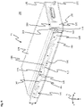
- the first housing shell 180 has the first outer side 100 and delimits a first housing interior 245 located on a side facing the viewer and a second housing interior 250 located on a side of the first housing shell 180 facing away from the viewer.
- the first housing interior 245 is connected by means of an in the first housing shell 180 formed second recess 255 fluidically connected to the second housing interior 250.
- the first housing shell 180 has a first housing section 260 , a second housing section 265 and a third housing section 305 .
- the housing sections 260, 265, 305 essentially extend two-dimensionally in the transverse direction and in the longitudinal direction.
- the first housing section 260 is offset in the transverse direction with respect to the second housing section 265 and the third housing section 305 and is connected to the second housing section 265 so that the first housing shell 180 has a stepped configuration.
- the first housing section 260 and the second housing section 265 extend in parallel yz planes.
- the first outside 100 is in figure 4 arranged on the rear of the second housing section 265 and the third housing section 305 .
- the first housing interior 245 is bounded in the transverse direction by the second housing interior 250 through the first to third housing sections 260, 265, 305.
- the first housing shell 180 has a first coil receptacle 270 on a side facing the first housing interior 245 .
- the first coil receptacle 270 is arranged to correspond to the arrangement of the stator tooth.
- a plurality of first coil receptacles 270 corresponding to the number of stator teeth provided are preferably arranged in the second housing section 265 .
- the first bobbin mount 270 has a first bobbin mount base 275 , a first bobbin mount side surface 280 , and a first bobbin mount opening 285 .
- the first coil pickup reason 275 separates the first housing interior 245 from an environment 290.
- the first coil receiving side surface 280 has a cross section that is designed to correspond essentially to the stator tooth 140 , 155 . It is particularly advantageous that the first coil-receiving side surface 280 tapers at least in sections from the first coil-receiving opening 285 to the first coil-receiving base 275 .
- figure 5 shows a further perspective view of the Figures 3 and 4 shown first housing shell 180.
- the third housing section 305 is arranged on a side of the second housing section 265 that faces away from the first housing section 260 and is connected to the second housing section 265 .
- the third housing section 305 tapers away from the first housing interior 245 in the transverse direction with increasing height.
- the first housing section 260 delimits the second housing interior 250 on the side facing away from the first housing interior 245.
- the second housing interior 250 serves to accommodate the sensor unit and the processing unit.
- the first housing shell 180 also has a first to fourth housing side section 310, 315, 320, 335.
- the housing sections 310, 315, 320, 335 extend on a common side of the housing section 260, 265, 305 and are aligned in a rectangular shape with respect to one another.
- the first housing side section 310 is arranged adjacent to the third housing section 305 on a side opposite to the second housing section 265, connected to the third housing section 305 and is perpendicularly oriented with respect to the first and second housing sections 260,265.
- the first housing side section 310 extends in the longitudinal direction essentially over an entire longitudinal extent of the first housing shell 180 and laterally delimits the first housing interior 245. Furthermore, the first housing side section 310 is aligned parallel to the running rail.
- the first housing shell 180 has the second housing side section 315 opposite the first housing side section 310 in the transverse direction.
- the second housing side portion 315 is adjacent to the first housing portion 260 on a side opposite to the second housing portion 265, is connected to the first housing portion 260, and is perpendicular to the first and second housing portions 260,265.
- the second housing side section 315 extends longitudinally over the entire length of the first housing shell 180 and laterally delimits the first housing interior 245 and the second housing interior 250.
- the first housing side section 310 and the second housing side section 315 are aligned in parallel.
- the third housing side section 320 is aligned perpendicularly to the housing section 260, 265 and to the first and/or second housing side section 310, 315 and is connected to the housing sections 260, 265, 305 and the first and second housing side sections 310, 315.
- the third housing side section 320 delimits the first and second housing interior 245, 250 on the first housing section 260 and the first housing interior 245 on the second and third housing section 265, 305 in the longitudinal direction (in figure 5 on a side facing away from the viewer).
- a groove 325 and a third recess 330 are provided in the third housing side section 320 .
- the third recess 330 is used to accommodate the first interface and is surrounded by a groove designed analogously to the recess 330, in which the in 3 illustrated fourth sealing element 200 is arranged. Included the third recess 330 is formed to correspond to the first interface 235.
- the groove 325 extends over the entire height of the third housing side section 320 and is designed to correspond to a first side of the further stator tooth. Another stator tooth is arranged in the groove 325 when the linear transport system is in the assembled state.
- the first housing shell 180 has the fourth housing side section 335 .
- the fourth housing section is connected to the housing sections 260,265,305 and the first and second housing side sections 310,315.
- the fourth housing side section 335 delimits the first and second housing interior 245, 250 in the longitudinal direction on the first housing section 260 and on the second and third housing section 265, 305 (in figure 5 on a side facing away from the viewer) the first housing interior 245.
- the fourth housing side section 335 and the third housing side section 320 are aligned parallel to one another and perpendicular to the first housing side section 310 and the second housing side section 315.
- a first shoulder 340 is provided on the second housing side section 315 .
- the first shoulder 340 has a first bearing surface 345 .
- the first bearing surface 345 is arranged in the transverse direction between the first outer side 100 and the first housing section 260 .
- the first bearing surface 345 is aligned parallel to the first outer side 100 and to the first housing section 260 .
- the first housing shell 180 has a second shoulder 350 for connecting the first housing section 260 to the second housing section 265 .
- the second shoulder 350 has a second bearing surface 355 arranged on a side of the second shoulder 350 that faces the first outer side 100 on, the second bearing surface 355 and the first bearing surface 345 being arranged in a common yz plane.
- the arrangement of a step on the third housing side section 320 and/or on the fourth housing side section 335 is dispensed with.
- FIG figure 6 shows a further perspective representation of the first housing shell 180 of FIG figure 3 shown first drive module 25.
- a further groove 360 is also arranged on the fourth housing side section 335, wherein the further groove 360 is designed to correspond to a second side of a further stator tooth.
- the further groove 360 is advantageously arranged in the z-direction at the level of the groove 325 . If the first drive module is correctly aligned on the second drive module, the further groove 360 and the groove 325 delimit a groove space in which a single further stator tooth 155 is arranged.
- a fourth recess 365 is provided on the fourth housing side section 335 .
- the fourth recess 365 is designed to correspond to the first and/or second interface 235, 240. The first interface is pushed into the second interface through the fourth recess 365 .
- a bolt receptacle 370 is provided on the fourth housing side section 335, wherein the bolt receptacle 370 is arranged between the fourth recess 365 and the second housing side section 315 in the vertical direction.
- the connecting bolt of the second connecting means 206 engages in the bolt receptacle 370 in order to connect the drive modules to one another.
- the fourth recess 370 can also be arranged on the third housing side section.
- figure 7 shows a further perspective representation of the first housing shell 180.
- the housing 125 has a first connecting profile 375 on the first housing shell 180 .
- the first connecting profile 375 has on the first housing side section 310 and on the second housing side section 315 a plurality of first bulges 380 which are spaced apart from one another in the longitudinal direction and extend in the height direction.
- the first bulge 380 has a trapezoidal cross section.
- the first bulges 380 are regularly spaced.
- the first connecting profile 375 also has a first receptacle 385 between two adjacently arranged first bulges 380 .
- the first connection profile 375 also has a second bulge 390 .
- a second bulge 390 is provided on the third housing side section 320 and on the fourth housing side section 335, mirror-symmetrical to a plane of symmetry 391, which is arranged centrally as the xz plane between the third housing side section 320 and the fourth housing side section 335.
- the second bulge 390 is formed differently from the first bulge 380 .
- the second bulge 390 extends transversely and is perpendicular to the first outer side.
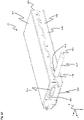
- figure 8 shows a perspective view of the second housing shell 190 of FIG figure 3 shown first drive module.
- the second housing shell 190 is used to close the first housing interior 245 from the environment 290 and at the same time a reliable fixation of the coil arrangement in the first housing interior 245.
- the second housing shell 190 has a cover section 395 which has a second outer side 400 on the outside.
- the cover portion 395 extends substantially in a yz plane and is aligned parallel to the first and second housing portions.
- the first to fourth housing side sections 310 , 315 , 320 , 335 are arranged laterally on one of the two sides of the cover section 395 on the cover section 395 and are connected to the cover section 395 .
- the first to fourth housing side sections 310, 315, 320, 335 of the second housing shell 190 are each arranged in alignment with the first to fourth housing side sections of the first housing shell.
- the second housing shell 190 has a second connection profile 376, which is designed to correspond to the first connection profile.
- the second connecting profile 376 has a third bulge 381 and a second receptacle 386 on the second housing shell 190 both on the first and on the second housing side section 310, 315, with the second receptacle 386 being arranged between two third bulges 381.
- the third bulge 381 is designed to correspond to the first receptacle arranged on the first housing shell. Furthermore, the second receptacle 386 arranged on the second housing shell 190 is designed to correspond to the first bulge arranged on the first housing shell 180 . Furthermore, the third bulge 381 on the second housing shell 190 is aligned in the longitudinal direction and in the transverse direction, i.e. opposite in the y direction and in the z direction, to the first receptacle on the first housing shell and the second receptacle 386 to the second Housing shell 190 is aligned with the first bulge on the first housing shell.
- the second connection profile 376 has a third receptacle 405 on the third housing side section 320 and on the fourth housing side section 335 in each case.
- the third receptacle 405 is designed to correspond to the second bulge on the first housing shell.
- the second bulge 390 can also be arranged on the second housing shell 190 and the third receptacle 405 can be arranged on the first housing shell 180 .
- the third receptacle 405 is arranged in alignment with the second bulge on the third housing side section and the fourth housing side section of the first housing shell.
- figure 9 shows a perspective view of the first drive module 25.
- first connection profile 375 and the second connection profile 376 engage in one another.
- the first bulge 380 thereby engages in the second receptacle 386 .
- the third bulge 381 engages in the first receptacle 385 .
- the second sealing element 185 is arranged between the first housing shell 180 and the second housing shell 190 in order to seal off the housing interior from the environment 290 . It is of particular advantage here if the second sealing element 185 is designed to be circumferential.
- At least one threaded bore 415 is arranged centrally in relation to a maximum height h of the first housing side section 310 in the first bulge 380 of the first housing shell 180, in which a further connecting element (not in figure 9 shown) can be attached to attach the slide rail to the first drive module 25.
- the central arrangement in relation to a maximum height h of the first housing side section 310 ensures that the running rail 35 is reliably supported on the first drive module 25 .
- the second housing shell 190 can be designed with particularly thin walls, so that the second housing shell 190 is particularly inexpensive and light. The forces from the first housing shell 180 are supported via the first housing shell 180 on the rear of the machine bed.
- the first housing shell 180 is preferably connected to the second housing shell 190 by means of the first connecting means 205, with the first connecting means 205 advantageously being arranged in the longitudinal direction at the level of the third bulge 381 and the first receptacle 385.
- the further stator tooth 155 is arranged in the groove 235, the end faces 145, 150 of the further stator tooth 155 being covered by the first sealing element 175 and the third sealing element 195.
- figure 10 shows a perspective view of the first drive module 25 in a second embodiment.
- the second bulge 390 engages in the third receptacle 405. This prevents the first housing shell 180 from being displaced relative to the second housing shell 190 in a second direction, in the transverse direction in the embodiment. This ensures that when the second housing shell 190 is placed on the first housing shell 180, the second housing shell 190 is reliably positioned relative to the first housing shell 180 and at the same time when the second housing shell 190 is connected to the first Housing shell 180, the second housing shell 190 cannot slip relative to the first housing shell 180.
- a first bushing 416 is provided in the first housing shell 180 in the second housing side section 315 , through which a power supply 417 is routed from the machine bed into the first drive module 25 . Furthermore, next to the first passage 416 there is a second passage 418 through which a data connection 419 is led into the drive module 25 . Furthermore, the second housing section 315 can be attached to the machine bed.
- figure 11 shows another perspective view of the in figure 10 illustrated first drive module 25.
- the cover element 170 is arranged on the first outer side 100 .
- the cover element 170 closes the second housing interior, which is arranged underneath the cover element 170, from the surroundings 290.
- the cover element 170 is formed like a film. In this case, the cover element 170 is bonded to the surface of the first outer side 100 by means of an adhesive layer.
- the covering element 170 together with the adhesive layer has a wall thickness of approximately 200 to 500 ⁇ m, particularly advantageously a wall thickness of 300 to 350 ⁇ m. It is particularly advantageous if the cover element 170 has a second material that is resistant to media, in particular to fats and oils, water and/or acids and/or bases. It is of particular advantage if the second material has polyester and/or Autotex EBA. In addition, the cover element 170 can have a layer of lacquer in order to adapt the visual impression of the first drive module 25 .
- figure 12 shows a perspective sectional view along an in figure 11 Section plane AA shown through the in figure 11 shown first drive module 25.
- the cutting plane AA is designed as an xz plane.
- the housing 125 is smooth on the outside.
- smooth is understood to mean that the housing 125 is designed essentially steplessly on the outside and is free of undercuts and/or joints.
- the housing 125 has an average roughness value R a on the outside, the average roughness value R a being in a range from 0.2 ⁇ m to 0.8 ⁇ m, in particular in a range from 0.4 ⁇ m to 0.8 ⁇ m. lies.
- the first outer side 100 and the second outer side 400 are predominantly (50%), preferably at least 75% of the area of the outer side 100, 400 planar. This reliably prevents adhesion and/or contamination of the housing 125 on the outside.
- the first housing shell 180 has a first sealing groove 420 on the circumference.
- the first sealing groove 420 is essentially formed following all of the housing side sections 310 , 315 .
- the first sealing element 175 is arranged in the first sealing groove 420 .
- the first sealing element 175 is designed to be circumferential, so that a reliable seal can be ensured on all four housing side sections 310, 315. This prevents media from penetrating into a gap 421 between the first drive module 25 and another component of the linear transport system 10 arranged on the first drive module 25, for example the running rail and/or the second drive module and/or the machine bed and/or a further first drive module be avoided.
- first housing shell 180 and the second housing shell 190 have on one of the respective other housing shells 180, 190 has a second sealing groove 425, the second sealing groove 425 being arranged in sections in the z-direction in the first housing shell 180 and in the second housing shell 190.
- the second sealing element 185 is arranged in the second sealing groove 425 in order to fluidly seal the housing interior 245 , 250 from the environment 290 .
- the second housing shell 190 also has a third sealing groove 430 on a side facing away from the first housing shell 180 towards the second outer side 400 .
- the third sealing groove 430 follows all housing side sections 310, 315 so as to run all the way around.
- the peripheral third sealing element 195 is arranged in order to seal the gap 421 on the first drive module 25 on all four housing side sections 310, 315.
- first sealing element 175 and/or the second sealing element 185 and/or the third sealing element 195 has at least one of the following third materials: fluoroketone, fluorocarbon, caoutchouc, fluoroelastomer, pigments that are designed in such a way that the Sealing element 175, 185, 195, 200 reflects light waves from a blue color spectrum.
- the sensor circuit board 220 and the sensor are arranged directly adjacent to the cover member 170 .
- Sensor printed circuit board 220 is preferably cohesively fastened on the inside to covering element 170 with adhesive layer 435, with which covering element 170 is adhesively bonded areally to first outer side 100.
- the distance between the sensor and the signal influencing device of the conveying device is particularly small.
- the thin-walled design of the cover element 170 ensures reliable transmission of the signal from the signal influencer to the sensor through the cover element 170 .
- sensor circuit board 220 rests on first bearing surface 345 on a first side and on second bearing surface 355 on a second side, so that sensor circuit board 220 is reliably positioned in second housing interior 250 on the rear.
- the processing unit 225 of the sensor unit 210 is arranged between the sensor circuit board 220 and the first housing section 260 of the first housing shell 180 .
- the processing unit 225 is fixed to the first housing section 260 .
- the driver unit 230 is arranged in the first housing interior 245 in the transverse direction between the second housing shell 190 and the first housing section 260 .
- the driver unit 230 is attached to the first housing section 260 of the first housing shell 180 .
- the coil arrangement 70 extends in the longitudinal direction of the housing 125.
- the stator tooth 140 and the further stator tooth are arranged transversely (running in the x-direction) in the first housing interior space 125.
- the outside 100, 400 is aligned parallel to the face 145, 150 of the stator tooth 140 and perpendicular to the stator tooth.
- the second housing shell 190 additionally has a second coil receptacle 440 arranged on a side facing the first housing interior 245 .
- the second bobbin mount 440 has a second bobbin mount base 445 , a second bobbin mount side surface 450 , and a second bobbin mount opening 455 .
- the second coil receptacle 440 is designed identically to the first coil receptacle 270, so that the second coil receptacle side surface 450 differs from the second Coil receiving opening 455 towards the second coil receiving base 445 tapers.
- the second coil receiving base 445 delimits the first housing interior 245 towards the second outside 400 and seals off the first housing interior 245 from the environment 290 .
- the wall thickness of the coil receiving base 275, 445 to the first outside 100, 400 is particularly small. It is of particular advantage if the wall thickness on the coil receiving base 275, 445 is in a range from 100 ⁇ m to 500 ⁇ m, advantageously in a range from 250 ⁇ m to 350 ⁇ m. This reliably ensures that the traveling field 120 emerges and that the traveling field 120 acts on the magnet arrangement of the conveying device. In particular, a distance between the magnet arrangement and the coil arrangement 70 is kept particularly small.
- first end face 145 of the stator tooth 140 bears against the first coil receiving base 275 and the stator tooth 140 engages in the second coil receptacle 440 in such a way that the second face side 150 of the stator tooth 140 bears against the second coil receiving base 445. This reliably prevents the coil 130 from tilting in the first housing interior 245 and, at the same time, the installation space requirement in the transverse direction for the first drive module 25 can be kept particularly low.
- a particularly stable fastening of the coils 130 in the housing 125 is ensured if a first coil receptacle 270 and a second coil receptacle 440 are provided for each coil 130, preferably for each stator tooth 140. This is particularly advantageous when the additional stator tooth is configured identically to the stator tooth 140 and the stator tooth 140 and the additional stator tooth 155 are provided for each coil 130 .
- the first housing interior 245 and/or the second housing interior 250 is essentially completely filled with a casting compound 460 .
- the casting compound 460 is preferably designed to be thermally conductive, so that heat is reliably dissipated from the coil arrangement 70 by the casting compound 460 and the coil arrangement 70 is thereby cooled. This reliably prevents the coil arrangement 70, in particular the coils 135, from overheating.
- the casting compound 460 has a plastic, in particular a duroplastic plastic, in particular a polyurethane.
- the casting compound 460 fixes the components arranged in the housing interior 245, 250, in particular the driver unit 230 and the sensor unit 210.
- the housing shells 180, 190 are prevented from becoming detached from one another. Furthermore, the potting compound 460 prevents liquid from penetrating and thus prevents damage to electrical and/or electronic components of the sensor unit 210 and the driver unit 230.
- the potting compound 460 enters from one housing interior, for example the second housing interior 250, via the second cutout 255 into the first housing interior 245, so that only when filling the potting compound 460 into one of the two housing interiors 245, 250 both housing interiors 245, 250 are reliably filled by the casting compound 460.
- the coil arrangement 70, the sensor unit 210 and the driver unit 230 are assembled in the first housing shell 180 in a first assembly step.
- all tolerance chains of the first drive module 25 can be based on the first housing shell 180 .
- the tolerance chains kept short by the reference to the first housing shell 180, so that the first drive module 25 has a high level of precision.
- the second housing shell 190 is fastened to the first housing shell 180 and the first housing interior 245 is thereby closed.
- the casting compound 460 is introduced into the second housing interior 250 .
- the potting compound 460 flows via the second recess 255 into the first housing interior 245.
- a fourth assembly step after the casting compound has at least partially cured, the cover element 170 is applied and the housing 125 is thereby completely closed.
- figure 13 shows a perspective view of the second drive module 30.
- the second drive module 30 is designed to be essentially identical to the first drive module. Deviating from this, the second drive module 30 is designed to run in an arc shape around a central axis 60 . As a result, the second housing side section can be dispensed with.
- the first housing side section 310 is arranged on the outside of the second drive module 30 and arranged to run on a circular path around the central axis 60 .
- the first housing side section 310 encloses an angle of 180°.
- the first housing side section 310 and/or the second drive module 30 can enclose a different angle.
- the arc shape can also be designed differently than shown. For example, the arc shape can be a clothoid.
- the third and fourth housing side sections 320, 335 are arranged in a common xz plane.
- the first drive module can be fastened to the third housing side section 320 by the second connecting means 206 , which is designed as a screw-in bolt in the embodiment.
- a further first drive module can be attached to the fourth housing side section 335 of the second drive module 30 with its third housing side section by means of the second connecting means 206 .
- an electrical connection of the first drive module to the second drive module 30 is ensured in each case by means of the interface 235, 240.
- the coil arrangement 70 (shown in dashed lines) is also arranged running in an arc shape around the center axis 60 .
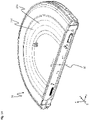
- figure 14 shows a perspective view of the second drive module 30.
- the cover element 170 is curved and closes the second housing interior 250.
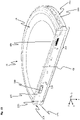
- figure 15 shows a perspective view of the first housing shell 180 of the second drive module 30.
- the first housing shell 180 of the second drive module 30 is essentially identical to the first housing shell 180 of the first drive module 25 . Deviating from this, the first housing interior 245 and the second housing interior 250 are arranged in a semicircle in relation to the central axis 60 . The first coil receptacles 270 are arranged on a circular path around the center axis 60 .
- the drive module 25, 30 smooth on the outside and the drive module 25, 30 can be easily cleaned. Furthermore, an accumulation or penetration of contaminants into the drive module 25, 30 is avoided.
- the interface 235, 240 By arranging the interface 235, 240 in the sealed area between the first sealing element 175 and the third sealing element 195, penetration of dirt or moisture into the interface 235, 240 is avoided. Furthermore, penetration is also avoided at the transition between the drive module 25, 30 and the running rail 35 and between the drive module 25, 30 and the machine bed 15. Sealing between the individual drive modules 25, 30 is also reliably achieved by the first and third sealing elements 175, 195.
- the arrangement of the second connecting means 206 in the area between the first sealing element 175 and the third sealing element 195 also prevents clogging of the second connecting means 206, so that the second connecting means 206 can be detached particularly easily, even after a long period of time and in a dirty environment 290, see above that a good dismantling work of the linear transport system 10, for example for maintenance work, is possible.
- the linear transport system 10 is particularly suitable for use in the food industry or the chemical industry or under conditions in which the linear transport system 10 is exposed to a high level of contamination.
- the configuration described above within the linear transport system 10 keeps a tolerance chain short, so that the linear transport system 10 has a particularly high level of precision and is easy to assemble.
- the internal arrangement of the coil arrangement 70 in the first housing interior 245 prevents corrosion of the coils 130, in particular the soft magnetic material of the stator tooth 140, 155, in particular a rust approach avoided.
Landscapes
- Engineering & Computer Science (AREA)
- Mechanical Engineering (AREA)
- Power Engineering (AREA)
- Physics & Mathematics (AREA)
- Electromagnetism (AREA)
- Transportation (AREA)
- Linear Motors (AREA)
Description
- Die Erfindung betrifft ein Antriebsmodul gemäß Patentanspruch 1 und ein Lineartransportsystem gemäß Patentanspruch 12.
- Aus der
DE 10 2012 204 916 A1 ist eine Statorvorrichtung für einen Linearmotor und ein lineares Transportsystem bekannt. Die Statorvorrichtung weist einen elektrisch bestrombaren Magnetfelderzeuger zum Bilden eines Magnetfeldes und eine erste Halteeinrichtung zum Halten des Magnetfelderzeugers auf. Der Magnetfelderzeuger ist an der ersten Halteeinrichtung befestigt und die erste Halteeinrichtung ist zumindest teilweise aus einem elektrisch und/oder magnetisch nichtleitenden Material gebildet. - Ferner sind auch aus der
US 2003/0230941 A1 ,US 2015/0027860 A1 ,US 2010/0276256 A1 ,DE 10 2012 103 378 A1 undDE 10 2011 017 525 A1 ,US 2016/0164395 A1 ,WO 2013/143783 A1 weitere lineare Transportvorrichtungen bekannt. - Ferner ist aus der
EP 2 560 904 B1 eine Transportvorrichtung zur Beförderung eines Produkts bekannt, wobei die Transportvorrichtung eine Vielzahl von unabhängig voneinander bewegbaren Förderelementen zum Fördern von Produkten, eine ortsfeste, umlaufend angeordnete Laufschiene, welche einen Laufpfad mit wenigstens einer Laufbahn für das Förderelement definiert und eine Linearmotorantriebsvorrichtung zum Antreiben der Förderelemente umfasst, wobei jedes Förderelement Permanentmagnete aufweist, die mit Spulen der Linearantriebsvorrichtung in Wirkverbindung stehen und wobei jedes Förderelement wenigstens ein erstes Teilelement und ein zweites Teilelement aufweist, welche mittels Gelenks gelenkig miteinander verbunden sind. Jedes Förderelement weist einen modularen Aufbau auf und die einzelnen Teilelemente einen gleichen Grundaufbau. Die Transporteinrichtung weist zahlreiche Hinterschneidungen und Spalten auf und ist somit aufwändig zu reinigen. - So können sich beispielsweise bei Einsatz der Transportvorrichtung bei der Herstellung von Lebensmitteln oder der Verpackung von Lebensmitteln in den Spalten und Hinterschneidungen Lebensmittelpartikel mit Keimen absetzen. Die Lebensmittelpartikel dienen dabei Keimen als Nährboden. Werden bei der Reinigung der Transporteinrichtung nicht alle Lebensmittelpartikel entfernt, kann die Transporteinrichtung die Keime bei der Herstellung der Lebensmittel auf die weiteren herzustellenden Lebensmittel übertragen und diese mit den Keimen infizieren.
- Es ist Aufgabe der Erfindung, ein besonders leicht zu reinigendes Antriebsmodul und ein leicht zu reinigendes Lineartransportsystem bereitzustellen, das insbesondere in einem Bereich, in dem hohe Verschmutzungen auftreten und/oder das Antriebsmodul und das Lineartransportsystem besonders sauber sein müssen, eingesetzt werden kann.
- Diese Aufgabe wird mittels eines Antriebsmoduls gemäß Patentanspruch 1 und eines Lineartransportsystems gemäß Patentanspruch 12 gelöst. Vorteilhafte Ausführungsformen sind in den abhängigen Ansprüchen angegeben.
- Es wurde erkannt, dass ein leicht zu reinigendes Antriebsmodul dadurch bereitgestellt werden kann, dass das Antriebsmodul ein Gehäuse und einen Stator aufweist, wobei an dem Gehäuse eine Fördereinrichtung des Lineartransportsystems mit einer Magnetanordnung anordnenbar ist, wobei das Gehäuse eine erste Gehäuseschale und eine zweite Gehäuseschale umfasst, wobei die erste Gehäuseschale und die zweite Gehäuseschale gemeinsam einen ersten Gehäuseinnenraum begrenzen, wobei in dem ersten Gehäuseinnenraum der Stator angeordnet ist, wobei der Stator wenigstens eine Spulenanordnung mit wenigstens einer Wicklung und wenigstens einem Statorzahn umfasst, wobei der Statorzahn eine erste Stirnfläche und eine zur ersten Stirnfläche gegenüber angeordnete zweite Stirnfläche aufweist, wobei die erste Stirnfläche innenseitig der ersten Gehäuseschale und die zweite Stirnfläche innenseitig der zweiten Gehäuseschale angeordnet sind, wobei die Gehäuseschalen den Statorzahn gegenüber einer Umgebung abdecken, wobei die Spulenanordnung ausgebildet ist, schaltbar ein magnetisches Wanderfeld bereitzustellen, wobei das Wanderfeld an den Stirnflächen aus der Spulenanordnung austritt und die Gehäuseschalen durchdringt, um außenseitig des Gehäuses zur Ausbildung einer magnetischen Kopplung in Wirkverbindung mit der Magnetanordnung der Fördereinrichtung des Lineartransportsystems zu treten.
- Dadurch wird ein Eindringen von aggressiven Reinigungsmedien, die dazu genutzt werden, um das Antriebsmodul von Verschmutzungen zu befreien und gegebenenfalls zu desinfizieren, in das Antriebsmodul vermieden. Durch die verbesserten Reinigungsmöglichkeiten werden Ablagerungsmöglichkeiten für Partikel, insbesondere Lebensmittelpartikel, die als Nährboden für Keime oder Pilze dienen können, zuverlässig entfernt. Ferner wird dadurch auf eine Keimübertragung auf ein Produkt, das mit dem Lineartransportsystem transportiert und/oder verarbeitet und/oder verpackt wird, vermieden. Ebenso wird eine Anhaftung von Partikeln an dem Antriebsmodul reduziert bzw. vermieden, so dass Reinigungsintervalle zur Reinigung des Antriebsmoduls gegenüber bekannten Antriebsmodulen verlängert sind. Dadurch eignet sich Antriebsmodul für den Einsatz in der Lebensmittelindustrie oder der pharmazeutischen Industrie, da mit dem Antriebsmodul hohe Hygienezertifizierungsstandards besonders gut erfüllt werden können. Ferner wird eine Korrosion am Stator durch die Gehäuseschalen vermieden.
- In einer weiteren Ausführungsform weist die erste Gehäuseschale eine erste Außenseite und die zweite Gehäuseschalte eine zweite Außenseite auf, wobei die erste Außenseite und/oder die zweite Außenseite im Wesentlichen glatt ausgebildet ist, wobei das Gehäuse außenseitig einen Mittelrauwert aufweist, wobei der Mittelrauwert in einem Bereich von 0,2 µm bis 0,8 µm, insbesondere in einem Bereich von 0,4 µm bis 0,8 µm, liegt. Dadurch kann das Gehäuse besonders einfach gereinigt werden. Ferner wird eine Anlagerung von Schmutz und/oder Partikeln durch die glatte Ausgestaltung der Außenseite zuverlässig vermieden.
- In einer weiteren Ausführungsform weist die erste Gehäuseschale eine erste Außenseite und die zweite Gehäuseschalte eine zweite Außenseite auf, wobei die erste Außenseite im Bereich der Spulenanordnung angeordnet ist, wobei die erste Außenseite im Wesentlichen plan ausgebildet ist. Ferner wird eine Partikelansammlung vermieden - insbesondere in schwer zu reinigenden Bereichen an Stößen, Ecken oder Hinterschneidungen - auf denen sich Keime oder Pilze anlagern können.
- In einer weiteren Ausführungsform weist die erste Gehäuseschale eine erste Außenseite und die zweite Gehäuseschalte eine zweite Außenseite auf, wobei die erste Gehäuseschale eine erste Spulenaufnahme aufweist, wobei die erste Spulenaufnahme einen ersten Spulenaufnahmegrund aufweist, wobei der erste Spulenaufnahmegrund zwischen der ersten Außenseite und der ersten Stirnseite des Statorzahns angeordnet ist und den ersten Gehäuseinnenraum gegenüber der Umgebung abtrennt, wobei die erste Spulenaufnahme zumindest abschnittsweise korrespondierend zu der Spule ausgebildet ist, wobei die Spule, insbesondere der Statorzahn in die erste Spulenaufnahme eingreift und vorzugsweise mit der ersten Stirnfläche an dem ersten Spulenaufnahmegrund anliegt, wobei die zweite Gehäuseschale eine gegenüberliegend zur ersten Spulenaufnahme angeordnete zweite Spulenaufnahme aufweist, wobei die zweite Spulenaufnahme einen zweiten Spulenaufnahmegrund aufweist, wobei der zweite Spulenaufnahmegrund zwischen der zweiten Außenseite und der zweiten Stirnseite des Statorzahns angeordnet ist und den ersten Gehäuseinnenraum gegenüber der Umgebung abtrennt, wobei die zweite Spulenaufnahme zumindest abschnittsweise korrespondierend zu der Spule, vorzugsweise dem Statorzahn, ausgebildet ist, wobei die Spule, insbesondere der Statorzahn in die zweite Spulenaufnahme eingreift und vorzugsweise mit der zweiten Stirnfläche an dem zweiten Spulenaufnahmegrund anliegt. Dadurch kann eine Position der Spule innerhalb des ersten Gehäuseinnenraums zuverlässig festgelegt werden. Insbesondere kann ein Verrutschen der Spule durch den Eingriff in die erste Spulenaufnahme vermieden werden. Dadurch wird eine Korrosion an der Spulenanordnung, insbesondere am Statorzahn, vermieden.
- In einer weiteren Ausführungsform sind für jede Spule, insbesondere für jeden Statorzahn, jeweils die erste Spulenaufnahme und die zweite Spulenaufnahme vorgesehen. Dadurch wird eine zuverlässige Positionierung und Befestigung der Spulenanordnung im ersten Gehäuseinnenraum sichergestellt.
- In einer weiteren Ausführungsform weist die Spule eine Wicklung um den Statorzahn und eine elektrische Isolierung auf, wobei die Isolierung plattenartig ausgebildet ist und wenigstens eine erste Aussparung aufweist, wobei die erste Aussparung korrespondierend zum Statorzahn ausgebildet ist, wobei der Statorzahn die erste Aussparung durchgreift, wobei die Isolierung zumindest zwischen einer der beiden Gehäuseschalen und der Wicklung angeordnet ist und die Wicklung elektrisch gegenüber dem Gehäuse isoliert.
- In einer weiteren Ausführungsform weist das Antriebsmodul eine Sensoreinheit zur Ermittlung einer Position der Fördereinrichtung an dem Antriebsmodul auf, wobei die erste Gehäuseschale auf einer zum ersten Gehäuseinnenraum abgewandten Seite einen zweiten Gehäuseinnenraum zumindest abschnittsweise begrenzt. In dem zweiten Gehäuseinnenraum ist die Sensoreinheit angeordnet. Dadurch kann das Antriebsmodul besonders kompakt ausgebildet sein.
- In einer weiteren Ausführungsform weist das Gehäuse ein Abdeckelement auf. Die Sensoreinheit weist einen Sensor auf. Das Abdeckelement ist an der ersten Außenseite der ersten Gehäuseschale angeordnet und verschließt den zweiten Gehäuseinnenraum gegenüber der Umgebung. Der Sensor ist angrenzend an das Abdeckelement angeordnet, wobei vorzugsweise das Abdeckelement folienartig ausgebildet ist. Vorzugsweise ist das Abdeckelement flächig mit der ersten Außenseite verklebt. Dadurch wird sichergestellt, dass der Sensor Signale eines Signalbeeinflussers der Fördereinrichtung zuverlässig empfangen kann und auf Grundlage des erfassten Signals zuverlässig eine Position der Fördereinrichtung an dem Antriebsmodul ermitteln werden kann.
- In einer weiteren Ausführungsform ist der erste Gehäuseinnenraum mit einer Vergussmasse verfüllt. Vorzugsweise ist die Vergussmasse wärmeleitend ausgebildet, um eine Wärme aus dem Stator abzuführen und den Stator zu kühlen. Vorzugsweise weist die Vergussmasse einen Kunststoff, insbesondere einen duroplastischen Kunststoff, insbesondere Polyurethan, auf.
- In einer weiteren Ausführungsform weist das Gehäuse wenigstens ein erstes Verbindungsprofil und ein zweites Verbindungsprofil zur Positionierung der zweiten Gehäuseschale relativ zur ersten Gehäuseschale auf, wobei das erste Verbindungsprofil an der einen Gehäuseschale und das zweite Verbindungsprofil an der anderen Gehäuseschale angeordnet ist, wobei das erste Verbindungsprofil wenigstens eine Ausbuchtung und das zweite Verbindungsprofil eine zur Ausbuchtung korrespondierend ausgebildete Aufnahme aufweist, wobei die Ausbuchtung sich in Richtung der anderen Gehäuseschale erstreckt, wobei die Ausbuchtung in die Aufnahme eingreift und eine Position der zweiten Gehäuseschale relativ zu der ersten Gehäuseschale zumindest in eine erste Richtung festlegt.
- In einer weiteren Ausführungsform weist das erste Verbindungsprofil wenigstens eine weitere Ausbuchtung und das zweite Verbindungsprofil eine zur weiteren Ausbuchtung korrespondierend ausgebildete weitere Aufnahme auf, wobei die weitere Ausbuchtung an der einen Gehäuseschale und die weitere Aufnahme an der anderen Gehäuseschale angeordnet sind, wobei die weitere Ausbuchtung sich in Richtung der anderen Gehäuseschale erstreckt, wobei vorzugsweise die Ausbuchtung und die weitere Ausbuchtung unterschiedlich zueinander ausgebildet sind, wobei die Aufnahme und die weitere Aufnahme vorzugsweise unterschiedlich zueinander ausgebildet sind, wobei die Aufnahme und die Ausbuchtung an einem Gehäuseseitenabschnitt des Gehäuses angeordnet sind, wobei die weitere Aufnahme und die weitere Ausbuchtung an einem weiteren Gehäuseseitenabschnitt des Gehäuses angeordnet sind, wobei vorzugsweise der Gehäuseseitenabschnitt und der weitere Gehäuseseitenabschnitt aneinander angrenzen, wobei die weitere Ausbuchtung in die weitere Aufnahme eingreift und eine Position der zweiten Gehäuseschale relativ zu der ersten Gehäuseschale zumindest in eine zweite Richtung quer zu der ersten Richtung festlegt. Dadurch kann zuverlässig die Position der zweiten Gehäuseschale relativ zu der ersten Gehäuseschale zweidimensional festgelegt werden.
- In einer weiteren Ausführungsform ist ein Verbindungsmittel vorgesehen, wobei das Verbindungsmittel an der ersten Ausbuchtung angeordnet ist, wobei vorzugsweise das Verbindungsmittel mittig bezogen auf eine maximale Erstreckung eines der Komponente zugewandten Gehäuseseitenabschnitts des Gehäuses angeordnet ist. Dadurch wird ein Drehmoment aus der Komponente zuverlässig im Gehäuse abgestützt und eine Aufbiegung der Gehäuseschale zuverlässig vermieden.
- In einer weiteren Ausführungsform weist das Gehäuse ein Dichtelement auf, wobei das Dichtelement ausgebildet ist, einen Spalt zwischen dem Antriebsmodul und einer weiteren Komponente, insbesondere einem weiteren Antriebsmodul des Lineartransportsystems, abzudichten, wobei vorzugsweise das erste Dichtelement umlaufend am Gehäuse angeordnet ist.
- Ebenso wurde erkannt, dass ein verbessertes Lineartransportsystem dadurch bereitgestellt werden kann, dass das Lineartransportsystem wenigstens ein Antriebsmodul, wenigstens eine Fördereinrichtung und wenigstens eine Laufschiene aufweist, wobei das Antriebsmodul wie oben beschrieben ausgebildet ist, wobei die Laufschiene an dem Antriebsmodul befestigt ist, wobei die Fördereinrichtung eine Führungsanordnung mit wenigstens einer Laufrolle und wenigstens eine versetzt zu der Laufrolle angeordnete Magnetanordnung umfasst, wobei die Laufrolle zur Führung der Fördereinrichtung entlang der Laufschiene an der Laufschiene anliegt, wobei zum Antrieb der Fördereinrichtung die Magnetanordnung außenseitig des Gehäuses im Wanderfeld des Stators anordenbar ist.
- In einer weiteren Ausführungsform weist die Fördereinrichtung einen Signalbeeinflusser auf, wobei der Signalbeeinflusser außenseitig an dem Abdeckelement angeordnet ist und ausgebildet ist, dem Sensor ein Signal bereitzustellen, wobei der Sensor ausgebildet ist, das Signal zu erfassen und der Verarbeitungseinheit bereitzustellen. Die Verarbeitungseinheit ist ausgebildet, auf Grundlage des bereitgestellten Signals eine Position der Fördereinrichtung an dem Antriebsmodul zu ermitteln. Dadurch kann das Wanderfeld besonders exakt positioniert werden, um die Fördereinrichtung mittels des Wanderfeldes entlang des Antriebsmoduls zu bewegen.
- In einer weiteren Ausführungsform weist das Lineartransportsystem ein weiteres Antriebsmodul auf, wobei das weitere Antriebsmodul wie oben beschrieben ausgebildet ist, wobei die Laufschiene an dem Antriebsmodul an einer Seite und das weitere Antriebsmodul an einer weiteren Seite des Antriebsmoduls befestigt ist.
- In einer weiteren Ausführungsform weist das Lineartransportsystem eine Vielzahl von Fördereinrichtungen auf, wobei die Fördereinrichtungen vorzugsweise identisch zueinander ausgebildet sind, wobei die Fördereinrichtungen durch das Antriebsmodul angetrieben werden.
- Nachfolgend wird die Erfindung anhand von Figuren näher erläutert. Dabei zeigen:
-
Figur 1 eine perspektivische Darstellung eines Lineartransportsystems; -
Figur 2 einen Ausschnitt A des inFigur 1 gezeigten Lineartransportsystems; -
Figur 3 eine Explosionsdarstellung eines ersten Antriebsmoduls des in denFiguren 1 und2 gezeigten Lineartransportsystems; -
Figuren 4 bis 7 perspektivische Darstellungen einer ersten Gehäuseschale des inFigur 3 gezeigten ersten Antriebsmoduls; -
Figur 8 eine perspektivische Darstellung einer zweiten Gehäuseschale des inFigur 3 gezeigten ersten Antriebsmoduls; -
Figure 9 eine perspektivische Ansicht des ersten Antriebsmoduls; -
Figuren 10 bis 11 perspektivische Ansichten des ersten Antriebsmoduls in einer zweiten Ausführungsform; -
Figur 12 eine perspektivische Schnittansicht entlang einer inFigur 11 gezeigten Schnittebene A-A durch das inFigur 11 gezeigte erste Antriebsmodul; -
Figuren 13 und14 perspektivische Darstellungen des zweiten Antriebsmoduls; und -
Figur 15 eine perspektivische Darstellung einer ersten Gehäuseschale des zweiten Antriebsmoduls. - Nachfolgend wird in den Figuren auf ein Koordinatensystem 5 Bezug genommen. Das Koordinatensystem 5 ist als Rechtssystem ausgebildet und weist eine x-Achse (Höhenrichtung), eine y-Achse (Längsrichtung) und eine z-Achse (Querrichtung) auf. Selbstverständlich kann das Koordinatensystem 5 auch andersartig ausgebildet sein.
-
Figur 1 zeigt eine perspektivische Darstellung eines Lineartransportsystems 10. - Das Lineartransportsystem 10 weist mehrere identisch zueinander ausgebildete Fördereinrichtungen 20, ein erstes Antriebsmodul 25, fakultativ wenigstens ein zweites Antriebsmodul 30 und eine Laufschiene 35 auf. Innenseitig sind die Antriebsmodule 25, 30 an einem Maschinenbett 15 befestigt. Außenseitig ist umlaufend an den Antriebsmodulen 25, 30 die Laufschiene 35 angeordnet. Die Fördereinrichtung 20 ist an der Laufschiene 35 befestigt und umgreift zumindest teilweise das Antriebsmodul 25, 30.
- In der hier dargestellten Ausführungsform sind pro Seite jeweils vier erste Antriebsmodule 25 in einer Reihe parallel zur y-Achse nebeneinander angeordnet, wobei an einem vorderen und hinteren Ende der Reihe der ersten Antriebsmodule 25 jeweils das zweite Antriebsmodul 30 angeordnet ist. Somit ergibt sich eine geschlossene, annähernd oval ausgebildete Form des Lineartransportsystems 10. Selbstverständlich können auch eine beliebige andere Anzahl an ersten Antriebsmodulen 25 und/oder anders geformte, insbesondere nur einen Winkelbereich von 22,5° oder 45° oder 90° oder einen beliebigen anderen Winkelbereich umfassende, zweite Antriebsmodule 30 zu einem erfindungsgemäßen Lineartransportsystem 10 zusammengesetzt werden. Dabei ist es noch nicht einmal zwingend erforderlich, dass dieses Lineartransportsystem 10 eine umlaufende geschlossene Kontur bildet.
- In der Ausführungsform erstrecken sich das erste Antriebsmodul 25 und ein an dem ersten Antriebsmodul 25 angeordneter erster Laufschienenabschnitt 50 in Längsrichtung parallel zur y-Achse. Ein zweiter Laufschienenabschnitt 55 ist halbkreisförmig ausgebildet, wobei korrespondierend zu der Ausgestaltung des zweiten Laufschienenabschnitts 55 das zweite Antriebsmodul 30 halbkreisförmig ausgebildet und angeordnet ist.
- Die Fördereinrichtung 20 ist gegenüber der Laufschiene 35 und dem Antriebsmodul 25, 30 bewegbar. In ihrer Bewegung wird die Fördereinrichtung 20 durch die Laufschiene 35 geführt. Dabei werden Kräfte, unter anderem beispielsweise Haltekräfte zum Transport eines Objekts an der Fördereinrichtung 20, von der Fördereinrichtung 20 an der Laufschiene 35 abgestützt. Die Kräfte werden von der Laufschiene 35 über das Antriebsmodul 25, 30 am Maschinenbett 15 abgestützt.
- Das Lineartransportsystem 10 weist ferner ein Steuergerät 40 und eine Antriebseinrichtung 45 auf. Das Steuergerät 40 ist mit den Antriebsmodulen 25, 30 verbunden. Die Antriebseinrichtung 45 ist als Linearmotor ausgebildet, wobei die Antriebseinrichtung 45 einen Stator 65 (strichliert dargestellt) und für jede Fördereinrichtung 20 eine Magnetanordnung 80 aufweist. Der Stator 65 weist für jedes Antriebsmodul 25, 30 eine Spulenanordnung 70 auf(strichliert dargestellt). Die Spulenanordnung 70 ist parallel zu dem jeweils an dem Antriebsmodul 25, 30 angeordneten Laufschienenabschnitt 50, 55 ausgerichtet. So ist im ersten Antriebsmodul 25 die Spulenanordnung 70 geradlinig parallel zur y-Achse und parallel zum ersten Laufschienenabschnitt 50 verlaufend ausgerichtet, während hingegen im zweiten Antriebsmodul 30 die Spulenanordnung 70 bogenförmig verlaufend angeordnet ist. Die Spulenanordnungen 70 sind jeweils mit dem Steuergerät 40 verbunden. Jede der Spulenanordnungen 70 weist wenigstens eine Spule 130 auf.
- Die Magnetanordnung 80 ist an der Fördereinrichtung 20 angeordnet. Die Magnetanordnung 80 ist jeweils seitlich des Stators 65 angeordnet.
- Das Steuergerät 40 ist ausgebildet, einen Spulenstrom durch eine vordefinierte Anzahl von Spulen, also einen Stromfluss durch die vordefinierte Anzahl von Spulen, zu variieren. Der Spulenstrom erzeugt ein magnetisches Wanderfeld das mit der Magnetanordnung 80 wechselwirkt.
- Das Steuergerät 40 ist dazu ausgebildet, die Bewegung der Fördereinrichtung 20 entlang der Laufschiene 35 zu steuern. Dabei steuert bzw. regelt das Steuergerät 40 die Spulenströme durch die Spulen derart, dass über die Wechselwirkung der Magnetanordnung 80 mit dem durch die Spulenströme erzeugten magnetischen Wanderfeld eine entlang bzw. längs des Antriebsmoduls 25, 30 gerichtete Kraft auf die Fördereinrichtung 20 ausgeübt wird. Dadurch kann jede Fördereinrichtung 20 eine zur anderen Fördereinrichtung 20 unterschiedliche Bewegung, beispielsweise eine unterschiedliche Bewegungsrichtung und/oder Beschleunigung und/oder Geschwindigkeit, durchführen.
-
Figur 2 zeigt den Ausschnitt A des inFigur 1 gezeigten Lineartransportsystems 10 in einer in Richtung des Betrachters gekippten Lage. - Die Fördereinrichtung 20 weist einen Träger 75 und eine Führungsanordnung 85 auf. Der Träger 75 ist U-förmig, vorzugsweise Hufeisen-förmig ausgebildet und umgreift sowohl die Laufschiene 35 als auch einen außenseitigen Abschnitt des ersten Antriebsmoduls 25. Die Führungsanordnung 85 ist mit dem Träger 75 verbunden und positioniert die Fördereinrichtung 20 an der Laufschiene 35. Die Führungsanordnung 85 umfasst in der Ausführungsform mehrere Laufrollen 115, die an der Laufschiene 35 abrollen und somit die Fördereinrichtung 20 relativ verschiebbar gegenüber der Laufschiene 35 positionieren.
- Zusätzlich umfasst das Lineartransportsystem 10 eine Positionserfassungseinrichtung 90. Die Positionserfassungseinrichtung 90 umfasst einen Signalbeeinflusser 95, der als Fahne ausgebildet und an einem Ende des Trägers 75 angeordnet ist. Der Signalbeeinflusser 95 ist plattenförmig ausgebildet, parallel zu einer ersten Außenseite 100 des ersten Antriebsmoduls 25 ausgerichtet und erstreckt sich in einer yz-Ebene. Der Signalbeeinflusser 95 ist beabstandet zu einer ersten Außenseite 100 des ersten Antriebsmoduls 25 angeordnet. Auf Höhe des Signalbeeinflussers 95 ist die erste Außenseite 100 plan ausgebildet.
- Seitlich angrenzend an den Signalbeeinflusser 95 umfasst die Magnetanordnung 80 einen ersten Magnetanordnungsabschnitt 105. Auf einer dem ersten Magnetanordnungsabschnitt 105 gegenüberliegenden Seite umfasst die Magnetanordnung 80 einen zweiten Magnetanordnungsabschnitt (in
Figur 2 durch die Laufschiene 35 und Teile des ersten Antriebsmoduls 25 verdeckt). Der Magnetanordnungsabschnitt 105 ist jeweils an dem Träger 75 befestigt. Jeder Magnetanordnungsabschnitt 105 kann ein oder mehreren Permanentmagneten, die in einer Reihe parallel zum ersten Laufschienenabschnitt 50 angeordnet sind, aufweisen. - Bei Aktivierung durch das Steuergerät 40 steuert bzw. regelt das Steuergerät die Spulenströme durch die Spulen 130 derart, dass über die Wechselwirkung der Magnetanordnung 80 mit dem durch die Spulenströme erzeugten magnetischen Wanderfelds eine entlang bzw. längs der Spulenanordnung gerichtete Kraft auf die Fördereinrichtung 20 ausgeübt wird.
- Die Antriebseinrichtung 45 kann beispielsweise als ein Synchron-Linearmotor ausgebildet sein. In diesem Fall werden in den Spulen 130 Spulenströme erzeugt, die ein mehrphasiges Wechselstromsignal bilden. Die Anzahl der Phasen des Wechselstromsignals und die gegenseitige Phasenlage der einzelnen Spulenströme bestimmen sich dabei nach der Geometrie der Anordnung der Spulen entlang der Spulenanordnung und nach der Geometrie der Magnetanordnung.
- Das Steuergerät 40 kann die Spulenanordnung 70 derart ansteuern, dass das Wanderfeld 120 bewegt wird. Durch die Kopplung der Magnetanordnung 80 mit dem Wanderfeld 120 wird die Fördereinrichtung 20 in der Bewegung des Wanderfelds 120 mitgenommen.
- Das Antriebsmodul 25, 30 umfasst ein Gehäuse 125. In dem Gehäuse 125 ist die Spulenanordnung 70 angeordnet. Das Gehäuse 125 weist wenigstens einen der folgenden ersten Werkstoffe auf: einen lebensmitteltechnisch hygienischen Werkstoff, Edelstahl, insbesondere einen V4A-Stahl, Kunststoff, Polyethylen, Polytetrafluorethylen.
- Das Gehäuse 125 ist außenseitig derart gestaltet, dass das Gehäuse 125 im Wesentlichen glatt ausgebildet ist. Dabei wird außenseitig an dem Gehäuse 125 auf Hinterschneidungen, (scharfkantige) Stöße, Vertiefungen oder Ähnliches verzichtet, sodass Anhaftungen von Verschmutzungen, beispielsweise Lebensmittelresten, besonders leicht von dem Gehäuse 125 entfernt werden können. Dadurch wird ein besonders hygienisches erstes Antriebsmodul 25, das insbesondere zur Herstellung von Lebensmitteln in der Lebensmittelindustrie einsetzbar ist, bereitgestellt.
-
Figur 3 zeigt eine Explosionsdarstellung des ersten Antriebsmoduls 25 des in denFiguren 1 und2 gezeigten Lineartransportsystems 10. - Die Spulenanordnung 70 des ersten Antriebsmoduls 25 weist in der Ausführungsform eine Vielzahl von Spulen 130 auf, die in einer Reihe parallel zur y-Achse, und somit parallel zum ersten Laufschienenabschnitt 55 nebeneinander angeordnet sind. Jede Spule 130 weist eine Wicklung 135 und wenigstens einen Statorzahn 140 auf. Eine Anzahl der Wicklungen 135 zu einer Anzahl von Statorzähnen 140 kann identisch oder unterschiedlich sein. Die Wicklung 135 ist umfangsseitig um den Statorzahn 140 angeordnet. Die Spulen 130 sind über die Länge des ersten Antriebsmoduls 25 angeordnet, über die die Fördereinrichtung während des Betriebs des Lineartransportsystems 10 verfahrbar ist. Im dargestellten Ausführungsbeispiel sind die Spulen 130 nicht überlappend angeordnet. Dabei sind die Spulen 130 zueinander jeweils in einem regelmäßigen Abstand nebeneinander angeordnet. In anderen Ausführungsbeispielen können die Spulen 130 aber auch überlappend angeordnet sein.
- Der Statorzahn 140 weist jeweils eine erste Stirnfläche 145 und eine in Querrichtung zum ersten Laufschienenabschnitt 55 gegenüberliegend angeordnete zweite Stirnfläche 150 auf.
- Die erste Stirnfläche 145 und die zweite Stirnfläche 150 sind parallel zueinander angeordnet. Die Spulenanordnung 70 umfasst zusätzlich zwischen zwei benachbart angeordneten Spulen 130 einen weiteren Statorzahn 155. Der weitere Statorzahn 155 ist identisch zu dem Statorzahn 140 ausgebildet. Der weitere Statorzahn 155 weist ebenso die erste und zweite Stirnfläche 145, 150 auf, wobei die erste Stirnfläche 145 des weiteren Statorzahns 155 in Querrichtung auf gleicher Höhe mit der ersten Stirnfläche 145 des Statorzahns 140 angeordnet ist. Ebenso ist die zweite Stirnfläche 150 des weiteren Statorzahns 155 in Querrichtung auf Höhe der zweiten Stirnseite 150 des Statorzahns 140 angeordnet. Um den weiteren Statorzahn 155 ist keine Wicklung 135 gewickelt.
- Jede der Wicklungen 135 ist durch das Steuergerät 40 separat mit elektrischer Energie zur Erzeugung des Wanderfelds beaufschlagbar. Das Wanderfeld 120 wird durch den Statorzahn 140, 155 gerichtet und tritt aus den Stirnflächen 145, 150 aus der Spulenanordnung 70 aus.
- Stirnseitig angrenzend an die Spule 130 ist eine plattenartig ausgebildete elektrische Isolierung 160 vorgesehen, wobei die Isolierung 160 wenigstens eine erste Aussparung 165 aufweist, wobei die erste Aussparung 165 korrespondierend zum Statorzahn 140, 155 ausgebildet ist. Der Statorzahn 140, 155 durchgreift die Isolierung 160. Eine Anzahl der vorgesehenen ersten Aussparungen 165 ist identisch zu einer Summe aus der Anzahl der Statorzähne 140 und der weiteren Statorzähne 155. Die Isolierung 160 ist beidseitig der Wicklungen 135 vorgesehen und in montiertem Zustand zwischen der Wicklung 135 und der Gehäuseschale 180, 190 angeordnet. Die Isolierung 160 isoliert elektrisch die Wicklung 135 gegenüber dem Gehäuse 125.
- Das Gehäuse 125 weist ein Abdeckelement 170, ein erstes Dichtelement 175, eine erste Gehäuseschale 180, ein zweites Dichtelement 185, eine zweite Gehäuseschale 190, ein drittes Dichtelement 195 und ein viertes Dichtelement 200 auf. Zusätzlich weist das Gehäuse 125 ein erstes Verbindungsmittel 205 auf, um die erste Gehäuseschale 180 mit der zweiten Gehäuseschale 190 und ein zweites Verbindungsmittel 206 um das erste Antriebsmodul 25 mit dem weiteren ersten Antriebsmodul und/oder dem zweiten Antriebsmodul zu verbinden. Das erste Verbindungsmittel 205 besteht in dem dargestellten Ausführungsbespiel aus in die erste Gehäuseschale 180 eingeschraubten Verbindungsbolzen 2051, die in entsprechende Bohrungen 2052 eingreifen, welche in der zweiten Gehäuseschale 190 entsprechend ausgebildet sind. Zur Verbindung der beiden Gehäuseschalen 180, 190 werden in Querrichtung zur Längserstreckung des Verbindungsbolzens 2051 zugehörige Gewindestifte 2053 in korrespondierend angeordnete Schraublöcher 2054 geschraubt, die in eine Eindrehung des Verbindungsbolzens 2051 eingreifen und so ein Lösen der Gehäuseschalen 180, 190 in Längserstreckung des Verbindungsbolzens 2051 verhindern. Das zweite Verbindungsmittel 206 ist im Wesentlichen identisch zu dem ersten Verbindungsmittel 205 aufgebaut und verbindet zwei benachbart angeordnete Antriebsmodule 25 miteinander. Abweichend dazu ist der Verbindungsbolzen 2051 des zweiten Verbindungsmittels 206 länger als der Verbindungsbolzen 2051 des ersten Verbindungsmittels 205 ausgebildet.
- Die Positionserfassungseinrichtung 90 umfasst zusätzlich zum Signalbeeinflusser eine Sensoreinheit 210 mit wenigstens einem Sensor 215, eine Sensorleiterplatte 220 und eine Verarbeitungseinheit 225. Der Sensor 215 ist auf der Sensorleiterplatte 220 angeordnet. Der Sensor 215 kann wenigstens eine Sensorwicklung aufweisen. Die Verarbeitungseinheit 225 ist beabstandet zu der Sensorleiterplatte 220 angeordnet und mittels der Sensorleiterplatte 220 elektrisch mit dem Sensor 215 verbunden.
- Der Sensor 215 erfasst bei Positionierung des Signalbeeinflussers 95 in der Nähe des Sensors 215. Die Verarbeitungseinheit 225 ermittelt auf Grundlage des Sensorsignals eine Position des Signalbeeinflussers auf dem ersten Antriebsmodul 25 und stellt diese dem Steuergerät bereit.
- Das erste Antriebsmodul 25 umfasst ferner eine Treibereinheit 230. Die Treibereinheit 230 weist eine erste Schnittstelle 235 und eine zweite Schnittstelle 240 auf. In Längsrichtung ist die erste Schnittstelle 235 gegenüberliegend zur zweiten Schnittstelle 240 angeordnet. Dabei ist in der Ausführungsform die erste Schnittstelle 235 als Buchsenkontakt ausgebildet, während hingegen die zweite Schnittstelle 240 als Steckkontakt ausgebildet ist. Die erste Schnittstelle 235 dient dazu, eine elektrische Verbindung zu der zweiten Schnittstelle des benachbarten Antriebsmoduls bereitzustellen.
- Die Treibereinheit 230 ist ferner elektrisch mit jeder der Wicklungen 135 und mit dem Steuergerät verbunden. Dabei dient die Treibereinheit 230 dazu, die Wicklungen 135 zur Erzeugung des Wanderfelds auf Grundlage eines Steuersignals des Steuergeräts anzusteuern. Das Steuergerät ermittelt das Steuersignal auf Grundlage der Position des Signalbeeinflussers an dem Antriebsmodul.
-
Figur 4 zeigt eine perspektivische Darstellung der ersten Gehäuseschale 180 des ersten Antriebsmoduls 25. - Die erste Gehäuseschale 180 weist die erste Außenseite 100 auf und begrenzt einen, auf einer dem Betrachter zugewandten Seite angeordneten ersten Gehäuseinnenraum 245 und einen, auf einer dem Betrachter abgewandten Seite der ersten Gehäuseschale 180 angeordneten zweiten Gehäuseinnenraum 250. Der erste Gehäuseinnenraum 245 ist mittels einer in der ersten Gehäuseschale 180 ausgebildeten zweiten Aussparung 255 mit dem zweiten Gehäuseinnenraum 250 fluidisch verbunden.
- Die erste Gehäuseschale 180 weist einen ersten Gehäuseabschnitt 260, einen zweiten Gehäuseabschnitt 265 und einen dritten Gehäuseabschnitt 305 auf. Die Gehäuseabschnitte 260, 265, 305 erstrecken sich im Wesentlichen zweidimensional in Querrichtung und in Längsrichtung.
- Der erste Gehäuseabschnitt 260 ist in Querrichtung versetzt zu dem zweiten Gehäuseabschnitt 265 und dem dritten Gehäuseabschnitt 305 angeordnet und mit dem zweiten Gehäuseabschnitt 265 verbunden, sodass die erste Gehäuseschale 180 eine gestufte Ausgestaltung aufweist. Der erste Gehäuseabschnitt 260 und der zweite Gehäuseabschnitt 265 erstrecken sich in jeweils parallel angeordneten yz-Ebenen. Die erste Außenseite 100 ist in
Figur 4 rückseitig an dem zweiten Gehäuseabschnitt 265 und dem dritten Gehäuseabschnitt 305 angeordnet. - Der erste Gehäuseinnenraum 245 wird in Querrichtung vom zweiten Gehäuseinnenraum 250 durch den ersten bis dritten Gehäuseabschnitt 260, 265, 305 begrenzt.
- Im zweiten Gehäuseabschnitt 265 weist die erste Gehäuseschale 180 auf einer zum ersten Gehäuseinnenraum 245 zugewandten Seite eine erste Spulenaufnahme 270 auf. Die erste Spulenaufnahme 270 ist korrespondierend zu der Anordnung des Statorzahns angeordnet. Vorzugsweise sind mehrere, korrespondierend zu der Anzahl der Statorzähne vorgesehenen ersten Spulenaufnahmen 270 in dem zweiten Gehäuseabschnitt 265 angeordnet.
- Die erste Spulenaufnahme 270 weist einen ersten Spulenaufnahmegrund 275, eine erste Spulenaufnahmeseitenfläche 280 und eine erste Spulenaufnahmeöffnung 285 auf. Der erste Spulenaufnahmegrund 275 trennt den ersten Gehäuseinnenraum 245 gegenüber einer Umgebung 290 ab.
- Die erste Spulenaufnahmeseitenfläche 280 weist einen im Wesentlichen korrespondierend zum Statorzahn 140, 155 ausgebildeten Querschnitt auf. Von besonderem Vorteil ist, dass die erste Spulenaufnahmeseitenfläche 280 von der ersten Spulenaufnahmeöffnung 285 zum ersten Spulenaufnahmegrund 275 hin sich zumindest abschnittsweise verjüngt.
-
Figur 5 zeigt eine weitere perspektivische Darstellung der in denFiguren 3 und4 gezeigten ersten Gehäuseschale 180. - Der dritte Gehäuseabschnitt 305 ist auf einer dem ersten Gehäuseabschnitt 260 abgewandten Seite des zweiten Gehäuseabschnitts 265 angeordnet und mit dem zweiten Gehäuseabschnitt 265 verbunden. Der dritte Gehäuseabschnitt 305 verjüngt sich mit zunehmender Höhe von dem ersten Gehäuseinnenraum 245 weg in Querrichtung.
- Der erste Gehäuseabschnitt 260 begrenzt auf der zum ersten Gehäuseinnenraum 245 abgewandten Seite den zweiten Gehäuseinnenraum 250. Der zweite Gehäuseinnenraum 250 dient zur Aufnahme der Sensoreinheit und der Verarbeitungseinheit.
- Die erste Gehäuseschale 180 weist ferner einen ersten bis vierten Gehäuseseitenabschnitt 310, 315, 320, 335 auf. Die Gehäuseabschnitte 310, 315, 320, 335 erstrecken sich auf einer gemeinsamen Seite des Gehäuseabschnitts 260, 265, 305 und sind rechteckförmig zueinander ausgerichtet.
- Der erste Gehäuseseitenabschnitt 310 ist angrenzend an den dritten Gehäuseabschnitt 305 auf einer zum zweiten Gehäuseabschnitt 265 abgewandten Seite angeordnet, mit dem dritten Gehäuseabschnitt 305 verbunden und ist senkrecht gegenüber dem ersten und zweiten Gehäuseabschnitt 260, 265 ausgerichtet. Der erste Gehäuseseitenabschnitt 310 erstreckt sich in Längsrichtung im Wesentlichen über eine gesamte Längserstreckung der ersten Gehäuseschale 180 und begrenzt seitlich den ersten Gehäuseinnenraum 245. Ferner ist der erste Gehäuseseitenabschnitt 310 parallel zu der Laufschiene ausgerichtet.
- In Querrichtung gegenüberliegend zum ersten Gehäuseseitenabschnitt 310 weist die erste Gehäuseschale 180 den zweiten Gehäuseseitenabschnitt 315 auf. Der zweite Gehäuseseitenabschnitt 315 grenzt an den ersten Gehäuseabschnitt 260 auf einer zum zweiten Gehäuseabschnitt 265 abgewandten Seite an, ist mit dem ersten Gehäuseabschnitt 260 verbunden und ist senkrecht zu dem ersten und zweiten Gehäuseabschnitt 260, 265 ausgerichtet. Der zweite Gehäuseseitenabschnitt 315 erstreckt sich in Längsrichtung über die gesamte Längserstreckung der ersten Gehäuseschale 180 und begrenzt seitlich den ersten Gehäuseinnenraum 245 und den zweiten Gehäuseinnenraum 250. Der erste Gehäuseseitenabschnitt 310 und der zweite Gehäuseseitenabschnitt 315 sind parallel ausgerichtet.
- Der dritte Gehäuseseitenabschnitt 320 ist senkrecht zu dem Gehäuseabschnitt 260, 265 und zu dem ersten und/oder zweiten Gehäuseseitenabschnitt 310, 315 ausgerichtet und mit den Gehäuseabschnitten 260, 265, 305 und dem ersten und zweiten Gehäuseseitenabschnitt 310, 315 verbunden. Der dritte Gehäuseseitenabschnitt 320 begrenzt am ersten Gehäuseabschnitt 260 den ersten und zweiten Gehäuseinnenraum 245, 250 und am zweiten und dritten Gehäuseabschnitt 265, 305 den ersten Gehäuseinnenraum 245 in Längsrichtung (in
Figur 5 auf einer dem Betrachter abgewandten Seite). Ferner ist im dritten Gehäuseseitenabschnitt 320 eine Nut 325 sowie eine dritte Aussparung 330 vorgesehen. Die dritte Aussparung 330 dient zur Aufnahme der ersten Schnittstelle und ist von einer analog zur Aussparung 330 ausgebildeten Nut umgeben, in der in montiertem Zustand des Lineartransportsystems das inFig. 3 dargestellte vierte Dichtelement 200 angeordnet ist. Dabei ist die dritte Aussparung 330 korrespondierend zur ersten Schnittstelle 235 ausgebildet. Die Nut 325 erstreckt sich über die gesamte Höhe des dritten Gehäuseseitenabschnitts 320 und ist korrespondierend zu einer ersten Seite des weiteren Statorzahns ausgebildet. In der Nut 325 ist ein weiterer Statorzahn in montiertem Zustand des Lineartransportsystems angeordnet. - In Längsrichtung gegenüberliegend zum dritten Gehäuseseitenabschnitt 320 weist die erste Gehäuseschale 180 den vierten Gehäuseseitenabschnitt 335 auf. Der vierte Gehäuseabschnitt ist mit den Gehäuseabschnitten 260, 265, 305 und dem ersten und zweiten Gehäuseseitenabschnitt 310, 315 verbunden. Der vierte Gehäuseseitenabschnitt 335 begrenzt am ersten Gehäuseabschnitt 260 den ersten und zweiten Gehäuseinnenraum 245, 250 in Längsrichtung und am zweiten und dritten Gehäuseabschnitt 265, 305 (in
Figur 5 auf einer dem Betrachter abgewandten Seite) den ersten Gehäuseinnenraum 245. In der Ausführungsform sind der vierte Gehäuseseitenabschnitt 335 und der dritte Gehäuseseitenabschnitt 320 parallel zueinander ausgerichtet und senkrecht zu dem ersten Gehäuseseitenabschnitt 310 und dem zweiten Gehäuseseitenabschnitt 315 ausgerichtet. - Am zweiten Gehäuseseitenabschnitt 315 ist ein erster Absatz 340 vorgesehen. Der erste Absatz 340 weist eine erste Auflagefläche 345 auf. Die erste Auflagefläche 345 ist in Querrichtung zwischen der ersten Außenseite 100 und dem ersten Gehäuseabschnitt 260 angeordnet. Die erste Auflagefläche 345 ist parallel zur ersten Außenseite 100 und zum ersten Gehäuseabschnitt 260 ausgerichtet.
- Die erste Gehäuseschale 180 weist zur Verbindung des ersten Gehäuseabschnitts 260 mit dem zweiten Gehäuseabschnitt 265 einen zweiten Absatz 350 auf. Der zweite Absatz 350 weist eine auf einer der ersten Außenseite 100 zugewandten Seite des zweiten Absatzes 350 angeordnete zweite Auflagefläche 355 auf, wobei die zweite Auflagefläche 355 und die erste Auflagefläche 345 in einer gemeinsamen yz-Ebene angeordnet sind. Um einen in Längsrichtung besonders langen ersten Gehäuseinnenraum 245 bereitzustellen, wird auf die Anordnung eines Absatzes am dritten Gehäuseseitenabschnitt 320 und/oder am vierten Gehäuseseitenabschnitt 335 verzichtet.
-
Figur 6 zeigt eine weitere perspektivische Darstellung der ersten Gehäuseschale 180 des inFigur 3 gezeigten ersten Antriebsmoduls 25. - Am vierten Gehäuseseitenabschnitt 335 ist ferner eine weitere Nut 360 angeordnet, wobei die weitere Nut 360 korrespondierend zu einer zweiten Seite eines weiteren Statorzahns ausgebildet ist. Vorteilhafterweise ist die weitere Nut 360 in z-Richtung auf Höhe der Nut 325 angeordnet. Die weitere Nut 360 und die Nut 325 begrenzen bei korrekter Ausrichtung des ersten Antriebsmoduls am zweiten Antriebsmodul einen Nutraum in dem ein einzelner weiterer Statorzahn 155 angeordnet ist.
- Ferner ist an dem vierten Gehäuseseitenabschnitt 335 eine vierte Aussparung 365 vorgesehen. Die vierte Aussparung 365 ist korrespondierend zur ersten und/oder zweiten Schnittstelle 235, 240 ausgebildet. Durch die vierte Aussparung 365 wird die erste Schnittstelle in die zweite Schnittstelle eingeschoben.
- Ferner ist am vierten Gehäuseseitenabschnitt 335 eine Bolzenaufnahme 370 vorgesehen, wobei die Bolzenaufnahme 370 in Höhenrichtung zwischen der vierten Aussparung 365 und dem zweiten Gehäuseseitenabschnitt 315 angeordnet ist. In die Bolzenaufnahme 370 greift in montiertem Zustand des Lineartransportsystems 10 der Verbindungsbolzen des zweiten Verbindungsmittels 206 ein, um die Antriebsmodule miteinander zu verbinden. Die vierte Aussparung 370 kann auch am dritten Gehäuseseitenabschnitt angeordnet sein.
-
Figur 7 zeigt eine weitere perspektivische Darstellung der ersten Gehäuseschale 180. - Um die erste Gehäuseschale 180 relativ zur zweiten Gehäuseschale zuverlässig zu positionieren, weist das Gehäuse 125 an der ersten Gehäuseschale 180 ein erstes Verbindungsprofil 375 auf. Das erste Verbindungsprofil 375 weist am ersten Gehäuseseitenabschnitt 310 und am zweiten Gehäuseseitenabschnitt 315 mehrere in Längsrichtung beabstandet zueinander angeordnete und sich in Höhenrichtung erstreckende erste Ausbuchtungen 380 auf. Die erste Ausbuchtung 380 weist einen trapezförmigen Querschnitt auf. Die ersten Ausbuchtungen 380 sind in regelmäßigem Abstand angeordnet. Ferner weist das erste Verbindungsprofil 375 zwischen zwei benachbart angeordneten ersten Ausbuchtungen 380 ferner eine erste Aufnahme 385 auf.
- Das erste Verbindungsprofil 375 weist zusätzlich eine zweite Ausbuchtung 390 auf. In der Ausführungsform ist jeweils je eine zweite Ausbuchtung 390 am dritten Gehäuseseitenabschnitt 320 und am vierten Gehäuseseitenabschnitt 335 spiegelsymmetrisch zu einer Symmetrieebene 391, die mittig als xz-Ebene zwischen dem dritten Gehäuseseitenabschnitt 320 und dem vierten Gehäuseseitenabschnitt 335 angeordnet ist, vorgesehen. Die zweite Ausbuchtung 390 ist unterschiedlich zur ersten Ausbuchtung 380 ausgebildet. Die zweite Ausbuchtung 390 erstreckt sich in Querrichtung und ist senkrecht zu der ersten Außenseite angeordnet.
-
Figur 8 zeigt eine perspektivische Darstellung der zweiten Gehäuseschale 190 des inFigur 3 gezeigten ersten Antriebsmoduls. - Die zweite Gehäuseschale 190 dient zum Verschließen des ersten Gehäuseinnenraums 245 gegenüber der Umgebung 290 und gleichzeitig einer zuverlässigen Fixierung der Spulenanordnung in dem ersten Gehäuseinnenraum 245.
- Die zweite Gehäuseschale 190 weist einen Deckelabschnitt 395 auf, der außenseitig eine zweite Außenseite 400 aufweist. Der Deckelabschnitt 395 erstreckt sich im Wesentlichen in einer yz-Ebene und ist parallel zum ersten und zweiten Gehäuseabschnitt ausgerichtet.
- Seitlich auf einer der beiden Seiten des Deckelabschnitts 395 ist am Deckelabschnitt 395 jeweils der erste bis vierte Gehäuseseitenabschnitt 310, 315, 320, 335 angeordnet und mit dem Deckelabschnitt 395 verbunden. Die ersten bis vierten Gehäuseseitenabschnitte 310, 315, 320, 335 der zweiten Gehäuseschale 190 sind jeweils fluchtend zum ersten bis vierten Gehäuseseitenabschnitt der ersten Gehäuseschale angeordnet.
- Die zweite Gehäuseschale 190 weist ein zweites Verbindungsprofil 376 auf, das korrespondierend zum ersten Verbindungsprofil ausgebildet ist. Das zweite Verbindungsprofil 376 weist an der zweiten Gehäuseschale 190 sowohl am ersten als auch am zweiten Gehäuseseitenabschnitt 310, 315 eine dritte Ausbuchtung 381 und eine zweite Aufnahme 386 auf, wobei die zweite Aufnahme 386 zwischen zwei dritten Ausbuchtungen 381 angeordnet ist.
- Die dritte Ausbuchtung 381 ist korrespondierend zu der an der ersten Gehäuseschale angeordneten ersten Aufnahme ausgebildet. Ferner ist die an der zweiten Gehäuseschale 190 angeordnete zweite Aufnahme 386 korrespondierend zu der an ersten Gehäuseschale 180 angeordneten ersten Ausbuchtung ausgebildet. Ferner ist in Längsrichtung und in Querrichtung die dritte Ausbuchtung 381 an der zweiten Gehäuseschale 190 fluchtend, das heißt in y-Richtung und in z-Richtung jeweils gegenüberliegend, zu der ersten Aufnahme an der ersten Gehäuseschale und die zweite Aufnahme 386 an der zweiten Gehäuseschale 190 fluchtend zu der ersten Ausbuchtung an der ersten Gehäuseschale ausgerichtet.
- Zusätzlich weist das zweite Verbindungsprofil 376 am dritten Gehäuseseitenabschnitt 320 und am vierten Gehäuseseitenabschnitt 335 jeweils eine dritte Aufnahme 405 auf. Die dritte Aufnahme 405 ist korrespondierend zu der zweiten Ausbuchtung an der ersten Gehäuseschale ausgebildet. Selbstverständlich kann auch die zweite Ausbuchtung 390 an der zweiten Gehäuseschale 190 und die dritte Aufnahme 405 an der ersten Gehäuseschale 180 angeordnet sein. Die dritte Aufnahme 405 ist jeweils fluchtend zu der zweiten Ausbuchtung an dem dritten Gehäuseseitenabschnitt und dem vierten Gehäuseseitenabschnitt der ersten Gehäuseschale angeordnet.
-
Figur 9 zeigt eine perspektivische Ansicht auf das erste Antriebsmodul 25. - In montiertem Zustand greifen das erste Verbindungsprofil 375 und das zweite Verbindungsprofil 376 ineinander ein. Dabei greift die erste Ausbuchtung 380 in die zweite Aufnahme 386 ein. Ferner greift die dritte Ausbuchtung 381 in die erste Aufnahme 385 ein. Dadurch wird eine Verschiebung der ersten Gehäuseschale 180 gegenüber der zweiten Gehäuseschale 190 in Längsrichtung vermieden. Zur Abdichtung des Gehäuseinnenraums gegenüber der Umgebung 290 ist das zweite Dichtelement 185 zwischen der ersten Gehäuseschale 180 und der zweiten Gehäuseschale 190 angeordnet. Von besonderem Vorteil ist hierbei, wenn das zweite Dichtelement 185 umlaufend ausgebildet ist.
- Von besonderem Vorteil ist, wenn mittig bezogen auf eine maximale Höhe h des ersten Gehäuseseitenabschnitts 310 in der ersten Ausbuchtung 380 der ersten Gehäuseschale 180 wenigstens eine Gewindebohrung 415 angeordnet ist, in der ein weiteres Verbindungselement (nicht in
Figur 9 dargestellt) befestigt werden kann, um die Laufschiene an dem ersten Antriebsmodul 25 zu befestigen. - Durch die mittige Anordnung bezogen auf eine maximale Höhe h des ersten Gehäuseseitenabschnitts 310 wird eine zuverlässige Abstützung der Laufschiene 35 an dem ersten Antriebsmodul 25 sichergestellt. Insbesondere kann dadurch die zweite Gehäuseschale 190 besonders dünnwandig ausgebildet werden, sodass die zweite Gehäuseschale 190 besonders kostengünstig und leicht ist. Die Abstützung der Kräfte aus der ersten Gehäuseschale 180 erfolgt über die erste Gehäuseschale 180 rückseitig am Maschinenbett.
- Vorzugsweise wird die erste Gehäuseschale 180 mit der zweiten Gehäuseschale 190 mittels des ersten Verbindungsmittels 205 verbunden, wobei vorteilhafterweise das erste Verbindungsmittel 205 in Längsrichtung auf Höhe der dritten Ausbuchtung 381 und der ersten Aufnahme 385 angeordnet ist.
- In der Nut 235 ist der weitere Statorzahn 155 angeordnet, wobei die Stirnflächen 145, 150 des weiteren Statorzahns 155 durch das erste Dichtelement 175 und das dritte Dichtelement 195 überdeckt sind.
-
Figur 10 zeigt eine perspektivische Darstellung des ersten Antriebsmoduls 25 in einer zweiten Ausführung. - Am dritten und vierten Gehäuseseitenabschnitt 320, 335 greift die zweite Ausbuchtung 390 in die dritte Aufnahme 405 ein. Dadurch wird eine Verschiebung der ersten Gehäuseschale 180 gegenüber der zweiten Gehäuseschale 190 in eine zweite Richtung, in der Ausführungsform der Querrichtung vermieden. Somit ist sichergestellt, dass bei aufgesetzter zweiter Gehäuseschale 190 auf der ersten Gehäuseschale 180 sowohl die zweite Gehäuseschale 190 gegenüber der ersten Gehäuseschale 180 zuverlässig positioniert ist und gleichzeitig bei dem Verbinden der zweiten Gehäuseschale 190 mit der ersten Gehäuseschale 180 die zweite Gehäuseschale 190 nicht gegenüber der ersten Gehäuseschale 180 verrutschen kann.
- In der hier dargestellten zweiten Ausführungsform des Antriebsmoduls 25 ist in der ersten Gehäuseschale 180 im zweiten Gehäuseseitenabschnitt 315 eine erste Durchführung 416 vorgesehen, durch die eine Stromversorgung 417 aus dem Maschinenbett in das erste Antriebsmodul 25 geführt ist. Ferner ist neben der ersten Durchführung 416 eine zweite Durchführung 418 angeordnet, durch die eine Datenverbindung 419 in das Antriebsmodul 25 geführt ist. Ferner kann der zweite Gehäuseabschnitt 315 am Maschinenbett befestigt werden.
-
Figur 11 zeigt eine weitere perspektivische Ansicht des inFigur 10 dargestellten ersten Antriebsmoduls 25. - An der ersten Außenseite 100 ist das Abdeckelement 170 angeordnet. Das Abdeckelement 170 verschließt den unterseitig unter dem Abdeckelement 170 angeordneten zweiten Gehäuseinnenraum gegenüber der Umgebung 290.
- Das Abdeckelement 170 ist folienartig ausgebildet. Dabei ist das Abdeckelement 170 mittels einer Klebschicht mit der ersten Außenseite 100 flächig verklebt.
- Von besonderem Vorteil ist, wenn das Abdeckelement 170 zusammen mit der Klebschicht eine Wandstärke von etwa 200 bis 500 µm, besonders vorteilhafterweise eine Wandstärke von 300 bis 350 µm aufweist. Von besonderem Vorteil ist, wenn das Abdeckelement 170 einen zweiten Werkstoff aufweist, der medienbeständig, insbesondere gegenüber Fetten und Ölen, Wasser und/oder Säuren und/oder Basen, ist. Von besonderem Vorteil ist, wenn der zweite Werkstoff Polyester und/oder Autotex EBA aufweist. Zusätzlich kann das Abdeckelement 170 eine Lackschicht aufweisen, um den optischen Eindruck des ersten Antriebsmoduls 25 anzupassen.
-
Figur 12 zeigt eine perspektivische Schnittansicht entlang einer inFigur 11 gezeigten Schnittebene A-A durch das inFigur 11 gezeigte erste Antriebsmodul 25. Die Schnittebene A-A ist als xz-Ebene ausgebildet. - Von besonderem Vorteil ist, wenn das Gehäuse 125 außenseitig glatt ausgebildet ist. Dabei wird unter glatt verstanden, dass außenseitig das Gehäuse 125 im Wesentlichen stufenlos ausgebildet ist und frei von Hinterschneidungen und/oder Stößen ist. Ferner ist von Vorteil, wenn das Gehäuse 125 außenseitig einen Mittelrauwert Ra aufweist, wobei der Mittelrauwert Ra in einem Bereich von 0,2 µm bis 0,8 µm, insbesondere in einem Bereich von 0,4 µm bis 0,8 µm, liegt. Die erste Außenseite 100 und die zweite Außenseite 400 sind überwiegend (50 %), vorzugsweise zu wenigstens 75 % der Fläche der Außenseite 100, 400, plan ausgebildet. Dadurch wird zuverlässig eine Anhaftung und/oder eine Verunreinigung des Gehäuses 125 außenseitig vermieden.
- Umfangsseitig weist die erste Gehäuseschale 180 eine erste Dichtnut 420 auf. Die erste Dichtnut 420 ist im Wesentlichen allen Gehäuseseitenabschnitten 310, 315 folgend ausgebildet. In der ersten Dichtnut 420 ist das erste Dichtelement 175 angeordnet. Das erste Dichtelement 175 ist umlaufend ausgebildet, sodass eine zuverlässige Abdichtung an allen vier Gehäuseseitenabschnitten 310, 315 sichergestellt werden kann. Dadurch kann eine Eindringen von Medien in eine Spalt 421 zwischen dem ersten Antriebsmodul 25 und einer an dem ersten Antriebsmodul 25 angeordneten weiteren Komponente des Lineartransportsystems 10, beispielsweise der Laufschiene und/oder dem zweiten Antriebsmodul und/oder dem Maschinenbett und/oder einem weiteren ersten Antriebsmodul vermieden werden.
- Ferner weist die erste Gehäuseschale 180 und die zweite Gehäuseschale 190 auf einer der jeweils anderen Gehäuseschale 180, 190 zugewandten Seite eine zweite Dichtnut 425 auf, wobei die zweite Dichtnut 425 in z-Richtung abschnittsweise in der ersten Gehäuseschale 180 und in der zweiten Gehäuseschale 190 angeordnet ist. In der zweiten Dichtnut 425 ist das zweite Dichtelement 185 angeordnet, um den Gehäuseinnenraum 245, 250 fluidisch gegenüber der Umgebung 290 abzudichten.
- Die zweite Gehäuseschale 190 weist ferner auf einer der ersten Gehäuseschale 180 abgewandten Seite hin zur zweiten Außenseite 400 eine dritte Dichtnut 430 auf. Die dritte Dichtnut 430 ist in der Ausführungsform allen Gehäuseseitenabschnitten 310, 315 folgend umlaufend ausgebildet. In der dritten Dichtnut 430 ist das umlaufend ausgebildete dritte Dichtelement 195 angeordnet, um an allen vier Gehäuseseitenabschnitten 310, 315 den Spalt 421 am ersten Antriebsmodul 25 abzudichten.
- Von besonderem Vorteil ist hierbei, wenn das erste Dichtelement 175 und/oder das zweite Dichtelement 185 und/oder das dritte Dichtelement 195 wenigstens einen der folgenden dritten Werkstoffe aufweist: Fluorketon, Fluorocarbon, Kautschuk, Fluorelastomer, Pigmentstoffe, die so ausgebildet sind, dass das Dichtelement 175, 185, 195, 200 Lichtwellen aus einem blauen Farbspektrum reflektiert.
- In der Ausführungsform sind die Sensorleiterplatte 220 und der Sensor direkt angrenzend an das Abdeckelement 170 angeordnet. Vorzugsweise ist die Sensorleiterplatte 220 mit der Klebschicht 435, mit der das Abdeckelement 170 flächig mit der ersten Außenseite 100 verklebt ist, innenseitig am Abdeckelement 170 stoffschlüssig befestigt. Dadurch ist ein Abstand des Sensors zu dem Signalbeeinflusser der Fördereinrichtung besonders gering. Ferner wird durch die dünnwandige Ausgestaltung des Abdeckelements 170 eine zuverlässige Übertragung des Signals vom Signalbeeinflusser auf den Sensor durch das Abdeckelement 170 sichergestellt. Rückseitig zu dem Abdeckelement 170 liegt die Sensorleiterplatte 220 auf der ersten Auflagefläche 345 an einer ersten Seite und auf der zweiten Auflagefläche 355 an einer zweiten Seite auf, sodass rückseitig die Sensorleiterplatte 220 zuverlässig in dem zweiten Gehäuseinnenraum 250 positioniert ist.
- Zwischen der Sensorleiterplatte 220 und dem ersten Gehäuseabschnitt 260 der ersten Gehäuseschale 180 ist die Verarbeitungseinheit 225 der Sensoreinheit 210 angeordnet. Die Verarbeitungseinheit 225 ist an dem ersten Gehäuseabschnitt 260 befestigt.
- In Querrichtung zwischen der zweiten Gehäuseschale 190 und dem ersten Gehäuseabschnitt 260 ist im ersten Gehäuseinnenraum 245 die Treibereinheit 230 angeordnet. Die Treibereinheit 230 ist an dem ersten Gehäuseabschnitt 260 der ersten Gehäuseschale 180 befestigt.
- Die Spulenanordnung 70 erstreckt sich in Längsrichtung des Gehäuses 125. Dabei sind der Statorzahn 140 und der weitere Statorzahn quer (x-Richtung verlaufend) in dem ersten Gehäuseinnenraum 125 angeordnet. Die Außenseite 100, 400 ist parallel zur Stirnfläche 145, 150 des Statorzahns 140 und senkrecht zum Statorzahn ausgerichtet.
- Um ein Verrutschen der Spulenanordnung 70 in dem Gehäuse 125 zu verhindern, weist die zweite Gehäuseschale 190 zusätzlich eine auf einer zum ersten Gehäuseinnenraum 245 zugewandten Seite angeordnete zweite Spulenaufnahme 440 auf. Die zweite Spulenaufnahme 440 weist einen zweiten Spulenaufnahmegrund 445, eine zweite Spulenaufnahmeseitenfläche 450 und eine zweite Spulenaufnahmeöffnung 455 auf. Die zweite Spulenaufnahme 440 ist identisch zur ersten Spulenaufnahme 270 ausgebildet, sodass sich die zweite Spulenaufnahmeseitenfläche 450 von der zweiten Spulenaufnahmeöffnung 455 hin zum zweiten Spulenaufnahmegrund 445 verjüngt. Der zweite Spulenaufnahmegrund 445 begrenzt den ersten Gehäuseinnenraum 245 hin zur zweiten Außenseite 400 und dichtet den ersten Gehäuseinnenraum 245 gegenüber der Umgebung 290 ab.
- Dabei ist von besonderem Vorteil, wenn die Wandstärke des Spulenaufnahmegrunds 275, 445 zu der ersten Außenseite 100, 400 besonders gering ist. Von besonderem Vorteil ist, wenn hierbei die Wandstärke an dem Spulenaufnahmegrund 275, 445 in einem Bereich von 100 µm bis 500 µm, vorteilhafterweise in einem Bereich von 250 µm bis 350 µm liegt. Dadurch wird ein Austreten des Wanderfelds 120 und ein Wirken des Wanderfelds 120 auf die Magnetanordnung der Fördereinrichtung zuverlässig sichergestellt. Insbesondere wird ein Abstand zwischen der Magnetanordnung und der Spulenanordnung 70 besonders gering gehalten.
- Ferner ist von Vorteil, wenn die erste Stirnseite 145 des Statorzahns 140 an dem ersten Spulenaufnahmegrund 275 anliegt und der Statorzahn 140 in die zweite Spulenaufnahme 440 derart eingreift, dass die zweite Stirnseite 150 des Statorzahns 140 an dem zweiten Spulenaufnahmegrund 445 anliegt. Dadurch wird ein Verkippen der Spule 130 in dem ersten Gehäuseinnenraum 245 zuverlässig vermieden und ferner kann gleichzeitig der Bauraumbedarf in Querrichtung für das erste Antriebsmodul 25 besonders gering gehalten werden.
- Eine besonders stabile Befestigung der Spulen 130 in dem Gehäuse 125 wird dann sichergestellt, wenn für jede Spule 130, vorzugsweise für jeden Statorzahn 140, jeweils eine erste Spulenaufnahme 270 und eine zweite Spulenaufnahme 440 vorgesehen ist. Dies ist insbesondere dann von Vorteil, wenn der weitere Statorzahn identisch zum Statorzahn 140 ausgebildet ist und für jede Spule 130 jeweils der Statorzahn 140 und der weitere Statorzahn 155 vorgesehen ist.
- Von besonderem Vorteil ist, wenn im Wesentlichen vollständig der erste Gehäuseinnenraum 245 und/oder der zweite Gehäuseinnenraum 250 mit einer Vergussmasse 460 verfüllt ist. Vorzugsweise ist die Vergussmasse 460 wärmeleitend ausgebildet, sodass eine Wärme aus der Spulenanordnung 70 durch die Vergussmasse 460 zuverlässig abgeführt wird und die Spulenanordnung 70 dadurch gekühlt wird. Dadurch wird eine Überhitzung der Spulenanordnung 70, insbesondere der Spulen 135, zuverlässig vermieden. Von besonderem Vorteil ist, wenn die Vergussmasse 460 einen Kunststoff, insbesondere einen duroplastischen Kunststoff, insbesondere ein Polyurethan, aufweist. Ferner fixiert die Vergussmasse 460 die im Gehäuseinnenraum 245, 250 angeordneten Komponenten, insbesondere die Treibereinheit 230 und die Sensoreinheit 210.
- Ferner wird ein Ablösen der Gehäuseschalen 180, 190 voneinander vermieden. Des Weiteren verhindert die Vergussmasse 460 ein Eindringen von Flüssigkeit und somit eine Beschädigung von elektrischen und/oder elektronischen Komponenten der Sensoreinheit 210 und der Treibereinheit 230.
- Wird die Vergussmasse 460 in den Gehäuseinnenraum 245, 250 gefüllt, so tritt die Vergussmasse 460 aus dem einen Gehäuseinnenraum, beispielsweise dem zweiten Gehäuseinnenraum 250, über die zweite Aussparung 255 in den ersten Gehäuseinnenraum 245 ein, sodass auch nur beim Einfüllen der Vergussmasse 460 in einen der beiden Gehäuseinnenräume 245, 250 beide Gehäuseinnenräume 245, 250 zuverlässig durch die Vergussmasse 460 verfüllt werden.
- In der Montage des ersten Antriebsmoduls 25, werden in einem ersten Montageschritt die Spulenanordnung 70, die Sensoreinheit 210 und die Treibereinheit 230 in der ersten Gehäuseschale 180 montiert. Dadurch können alle Toleranzketten des ersten Antriebsmoduls 25 auf der erste Gehäuseschale 180 basieren. Auch sind die Toleranzketten durch die Referenz auf die erste Gehäuseschale 180 kurz gehalten, so dass das erste Antriebsmodul 25 eine hohe Präzision aufweist.
- In einem zweiten Montageschritt wird nach Montage der Komponenten an der ersten Gehäuseschale 180 die zweite Gehäuseschale 190 an der ersten Gehäuseschale 180 befestigt und der erste Gehäuseinnenraum 245 dadurch verschlossen.
- In einem dritten Montageschritt wird die Vergussmasse 460 in den zweiten Gehäuseinnenraum 250 eingebracht. Die Vergussmasse 460 fließt über die zweite Aussparung 255 in den ersten Gehäuseinnenraum 245.
- In einem vierten Montageschritt wird nach zumindest teilweisem Aushärten der Vergussmasse das Abdeckelement 170 aufgebracht und das Gehäuse 125 dadurch vollständig verschlossen.
-
Figur 13 zeigt eine perspektivische Darstellung des zweiten Antriebsmoduls 30. - Das zweite Antriebsmodul 30 ist im Wesentlichen identisch zu dem ersten Antriebsmodul ausgebildet. Abweichend dazu ist das zweite Antriebsmodul 30 bogenförmig um eine Mittelachse 60 verlaufend ausgebildet. Dadurch kann auf den zweiten Gehäuseseitenabschnitt verzichtet werden. Der erste Gehäuseseitenabschnitt 310 ist außenseitig des zweiten Antriebsmoduls 30 angeordnet und auf einer Kreisbahn um die Mittelachse 60 verlaufend angeordnet. Dabei schließt der erste Gehäuseseitenabschnitt 310 einen Winkel von 180° ein. Selbstverständlich können der erste Gehäuseseitenabschnitt 310 und/oder das zweite Antriebsmodul 30 einen anderen Winkel einschließen. Auch kann die Bogenform anders als gezeigt ausgebildet sein. Beispielsweise kann es sich bei der Bogenform um eine Klothoide handeln.
- Der dritte und vierte Gehäuseseitenabschnitt 320, 335 sind in einer gemeinsamen xz-Ebene angeordnet. Durch das zweite Verbindungsmittel 206, das in der Ausführungsform als Einschraubbolzen ausgebildet ist, kann am dritten Gehäuseseitenabschnitt 320 das erste Antriebsmodul befestigt werden. Am vierten Gehäuseseitenabschnitt 335 des zweiten Antriebsmoduls 30 kann ein weiteres erstes Antriebsmodul mit seinem dritten Gehäuseseitenabschnitt mittels des zweiten Verbindungsmittels 206 befestigt werden. Dabei wird jeweils mittels der Schnittstelle 235, 240 eine elektrische Verbindung des ersten Antriebsmoduls zu dem zweiten Antriebsmodul 30 sichergestellt.
- Korrespondierend zu der bogenförmigen Ausgestaltung konzentrisch um die Mittelachse 60 verlaufend ist ebenso die Spulenanordnung 70 (strichliert dargestellt) bogenförmig um die Mittelachse 60 verlaufend angeordnet.
-
Figur 14 zeigt eine perspektivische Darstellung des zweiten Antriebsmoduls 30. - Das Abdeckelement 170 ist bogenförmig ausgestaltet und verschließt den zweiten Gehäuseinnenraum 250.
-
Figur 15 zeigt eine perspektivische Darstellung der ersten Gehäuseschale 180 des zweiten Antriebsmoduls 30. - Die erste Gehäuseschale 180 des zweiten Antriebsmoduls 30 ist im Wesentlichen identisch zu der ersten Gehäuseschale 180 des ersten Antriebsmoduls 25 ausgebildet. Abweichend dazu sind der erste Gehäuseinnenraum 245 und der zweite Gehäuseinnenraum 250 halbkreisförmig bezogen auf die Mittelachse 60 angeordnet. Die ersten Spulenaufnahmen 270 sind auf einer Kreisbahn um die Mittelachse 60 angeordnet.
- Durch die in den Figuren beschrieben Ausgestaltung des Lineartransportsystems 10 ist das Antriebsmodul 25, 30 außenseitig glatt ausgebildet und es kann das Antriebsmodul 25, 30 leicht gereinigt werden. Ferner wird eine Ansammlung bzw. ein Eindringen von Verunreinigungen in das Antriebsmodul 25, 30 vermieden.
- Durch die Anordnung der Schnittstelle 235, 240 im abgedichteten Bereich zwischen dem ersten Dichtelement 175 und dem dritten Dichtelement 195 wird ein Eindringen von Schmutz oder Feuchtigkeit in die Schnittstelle 235, 240 vermieden. Ferner wird das Eindringen ebenso an dem Übergang zwischen dem Antriebsmodul 25, 30 und der Laufschiene 35 sowie zwischen dem Antriebsmodul 25, 30 und dem Maschinenbett 15 vermieden. Auch wird zuverlässig eine Abdichtung zwischen den einzelnen Antriebsmodulen 25, 30 durch das erste und dritte Dichtelement 175, 195 erzielt. Durch die Anordnung des zweiten Verbindungsmittels 206 im Bereich zwischen dem ersten Dichtelement 175 und dem dritten Dichtelement 195 wird auch ein Zusetzen des zweiten Verbindungsmittels 206 vermieden, so dass das zweite Verbindungsmittel 206 besonders leicht auch nach langer Zeit und in schmutziger Umgebung 290 lösbar ist, so dass eine gute Demontagearbeit des Lineartransportsystems 10, beispielsweise für Wartungsarbeiten, möglich ist.
- Durch die hermetische Abdichtung des Lineartransportsystems 10 eignet sich das Lineartransportsystem 10 insbesondere zum Einsatz in der Lebensmittelindustrie oder der chemischen Industrie oder unter Bedingungen, bei denen das Lineartransportsystem 10 hohen Verschmutzungen ausgesetzt ist.
- Ferner wird durch die oben beschriebene Ausgestaltung innerhalb des Lineartransportsystems 10 eine Toleranzkette kurz gehalten, sodass das Lineartransportsystem 10 eine besonders hohe Präzision aufweist und leicht montierbar ist.
- Durch die innenseitige Anordnung der Spulenanordnung 70 im ersten Gehäuseinnenraum 245 wird eine Korrosion der Spulen 130, insbesondere des weichmagnetischen Materials des Statorzahns 140, 155, insbesondere ein Rostansatz, vermieden.
-
- 10
- Transportsystem
- 15
- Maschinenbett
- 20
- Fördereinrichtungen
- 25
- erstes Antriebsmodul
- 30
- zweites Antriebsmodul
- 35
- Laufschiene
- 40
- Steuergerät
- 45
- Antriebseinrichtung
- 50
- erster Laufschienenabschnitt
- 55
- zweiter Laufschienenabschnitt
- 60
- Mittelachse
- 65
- Stator
- 70
- Spulenanordnung
- 75
- Träger
- 80
- Magnetanordnung
- 85
- Führungsanordnung
- 90
- Positionserfassungseinrichtung
- 95
- Signalgeber
- 100
- erste Außenseite
- 105
- erster Magnetanordnungsabschnitt
- 115
- Laufrolle
- 120
- Wanderfeld
- 125
- Gehäuse
- 130
- Spule
- 135
- Wicklung
- 140
- Spulenkern
- 145
- erste Stirnfläche
- 150
- zweite Stirnfläche
- 155
- weiterer Spulenkern
- 160
- Isolierung
- 165
- erste Aussparung
- 170
- Abdeckelement
- 175
- erstes Dichtelement
- 180
- erste Gehäuseschale
- 185
- zweites Dichtelement
- 190
- zweite Gehäuseschale
- 195
- drittes Dichtelement
- 200
- viertes Dichtelement
- 205
- erstes Verbindungsmittel
- 206
- zweites Verbindungsmittel
- 210
- Sensoreinheit
- 215
- Sensor
- 220
- Sensorleiterplatte
- 225
- Verarbeitungseinheit
- 230
- Treibereinheit
- 235
- erste Schnittstelle
- 240
- zweite Schnittstelle
- 245
- erster Gehäuseinnenraum
- 250
- zweiter Gehäuseinnenraum
- 255
- zweite Aussparung
- 260
- erster Gehäuseabschnitt
- 265
- zweiter Gehäuseabschnitt
- 270
- erste Spulenaufnahme
- 275
- erster Spulenaufnahmegrund
- 280
- erste Spulenaufnahmeseitenfläche
- 285
- erste Spulenaufnahmeöffnung
- 290
- Umgebung
- 305
- dritter Gehäuseabschnitt
- 310
- erster Gehäuseseitenabschnitt
- 315
- zweiter Gehäuseseitenabschnitt
- 320
- dritter Gehäuseseitenabschnitt
- 325
- Nut
- 330
- dritte Aussparung
- 335
- vierter Gehäuseseitenabschnitt
- 340
- erster Absatz
- 345
- erste Auflagefläche
- 350
- zweiter Absatz
- 355
- zweite Auflagefläche
- 360
- weitere Nut
- 365
- vierte Aussparung
- 370
- fünfte Aussparung
- 375
- erstes Verbindungsprofil
- 376
- zweites Verbindungsprofil
- 380
- erste Ausbuchtung
- 381
- dritte Ausbuchtung
- 385
- erste Aufnahme
- 386
- zweite Aufnahme
- 390
- zweite Ausbuchtung
- 391
- Symmetrieebene
- 395
- Deckelabschnitt
- 400
- zweite Außenseite
- 405
- dritte Aufnahme
- 415
- Gewindebohrung
- 416
- erste Durchführung
- 420
- erste Dichtnut
- 421
- Spalt
- 425
- zweite Dichtnut
- 430
- dritte Dichtnut
- 435
- Klebschicht
- 440
- zweite Spulenaufnahme
- 445
- zweiter Spulenaufnahmegrund
- 450
- zweite Spulenaufnahmeseitenfläche
- 455
- zweite Spulenaufnahmeöffnung
- 460
- Vergussmasse
- x
- Höhenrichtung
- y
- Längsrichtung
- z
- Querrichtung
Claims (15)
- Antriebsmodul (25, 30) für ein Lineartransportsystem (10),- aufweisend ein Gehäuse (125) und einen Stator (65),- wobei an dem Gehäuse eine Fördereinrichtung (20) des Lineartransportsystems (10) mit einer Magnetanordnung (80) anordnenbar ist,- wobei das Gehäuse eine erste Gehäuseschale (180) und eine zweite Gehäuseschale (190) umfasst,- wobei die erste Gehäuseschale (180) und die zweite Gehäuseschale (190) gemeinsam einen ersten Gehäuseinnenraum (245) begrenzen,- wobei in dem ersten Gehäuseinnenraum (245) der Stator (65) angeordnet ist,- wobei der Stator (65) wenigstens eine Spulenanordnung (70) mit wenigstens einer Spule (130) mit wenigstens einem Statorzahn (140, 155) umfasst,- wobei die Spulenanordnung (70) ausgebildet ist, schaltbar ein magnetisches Wanderfeld (120) bereitzustellen,- wobei der Statorzahn (140, 155) eine erste Stirnfläche (145) und eine zur ersten Stirnfläche (145) gegenüber angeordnete zweite Stirnfläche (150) aufweist,- wobei die erste Stirnfläche (145) innenseitig der ersten Gehäuseschale (180) und die zweite Stirnfläche (150) innenseitig der zweiten Gehäuseschale (190) angeordnet sind,- wobei die Gehäuseschalen (180, 190) den Statorzahn (140, 155) gegenüber einer Umgebung (290) abdecken, dadurch gekennzeichnet, dassdas Wanderfeld (120) an den Stirnflächen (145, 150) aus der Spulenanordnung (70) austritt und die Gehäuseschalen (180, 190) durchdringt, um außenseitig des Gehäuses (125) zur Ausbildung einer magnetischen Kopplung in Wirkverbindung mit der Magnetanordnung (80) der Fördereinrichtung (20) des Lineartransportsystems (10) zu treten.
- Antriebsmodul (25, 30) nach Anspruch 1,- wobei die erste Gehäuseschale (180) eine erste Außenseite (100) und die zweite Gehäuseschale (190) eine zweite Außenseite (400) aufweist,- wobei die erste Außenseite (100) und/oder die zweite Außenseite (400) im Wesentlichen glatt ausgebildet ist,- wobei das Gehäuse (125) außenseitig einen Mittelrauwert (Ra) aufweist,- wobei der Mittelrauwert (Ra) in einem Bereich von 0,2 µm bis 0,8 µm, insbesondere in einem Bereich von 0,4 µm bis 0,8 µm, liegt,
und/oder- wobei die erste Gehäuseschale (180) eine erste Außenseite (100) und die zweite Gehäuseschale (190) eine zweite Außenseite (400) aufweist,- wobei die erste Außenseite (100) im Bereich der Spulenanordnung (70) angeordnet ist,- wobei die erste Außenseite (100) im Wesentlichen plan ausgebildet ist,- und/oder- wobei das Gehäuse (125) ein Dichtelement (175, 195) aufweist,- wobei das Dichtelement (175, 195) umlaufend am Gehäuse (125) angeordnet ist,- wobei das Dichtelement (175, 195) ausgebildet ist, einen Spalt (421) zwischen dem Antriebsmodul (25, 30) und einer weiteren Komponente, insbesondere einem weiteren Antriebsmodul (25, 30) des Lineartransportsystems (10), abzudichten. - Antriebsmodul (25, 30) nach einem der vorhergehenden Ansprüche,- wobei die erste Gehäuseschale (180) eine erste Außenseite (100) und die zweite Gehäuseschale (190) eine zweite Außenseite (400) aufweist,- wobei die erste Gehäuseschale (180) eine erste Spulenaufnahme (270) aufweist,- wobei die erste Spulenaufnahme (270) einen ersten Spulenaufnahmegrund (275) aufweist,- wobei der erste Spulenaufnahmegrund (275) zwischen der ersten Außenseite (100) und der ersten Stirnseite (145) des Statorzahns (140, 155) angeordnet ist und den ersten Gehäuseinnenraum (245) gegenüber der Umgebung (290) abtrennt,- wobei die erste Spulenaufnahme (270) zumindest abschnittsweise korrespondierend zu der Spule (130), insbesondere zu dem Statorzahn (140, 155), ausgebildet ist,- wobei die Spule (130), insbesondere der Statorzahn (140, 155), in die erste Spulenaufnahme (270) eingreift und vorzugsweise mit der ersten Stirnfläche (145) an dem ersten Spulenaufnahmegrund (275) anliegt,- wobei die zweite Gehäuseschale (190) eine gegenüberliegend zur ersten Spulenaufnahme (270) angeordnete zweite Spulenaufnahme (440) aufweist,- wobei die zweite Spulenaufnahme (440) einen zweiten Spulenaufnahmegrund (445) aufweist,- wobei der zweite Spulenaufnahmegrund (445) zwischen der zweiten Außenseite (400) und der zweiten Stirnseite (150) des Statorzahns (140, 155) angeordnet ist und den ersten Gehäuseinnenraum (245) gegenüber der Umgebung (290) abtrennt,- wobei die zweite Spulenaufnahme (440) zumindest abschnittsweise korrespondierend zu der Spule (130), vorzugsweise dem Statorzahn (140, 155), ausgebildet ist,- wobei die Spule (130), insbesondere der Statorzahn (140, 155), in die zweite Spulenaufnahme (440)eingreift und vorzugsweise mit der zweiten Stirnfläche (150) an dem zweiten Spulenaufnahmegrund (445) anliegt.
- Antriebsmodul (25, 30) nach Anspruch 3,- wobei wenigstens eine der beiden Spulenaufnahmen (270, 440) eine Spulenaufnahmeseitenfläche (280, 450) und eine Spulenaufnahmeöffnung (285, 455) aufweist,- wobei die Spulenaufnahmeseitenfläche (280, 450) von der Spulenaufnahmeöffnung (285, 450) hin zum Spulenaufnahmegrund (275, 445) zumindest abschnittweise verjüngend ausgebildet ist.
- Antriebsmodul (25, 30) nach Anspruch 4,- wobei für jede Spule (130), insbesondere für jeden Statorzahn (140, 155), jeweils die erste Spulenaufnahme (270) und die zweite Spulenaufnahme (440) vorgesehen ist.
- Antriebsmodul (25, 30) nach einem der Ansprüche 3 bis 5,- wobei die Spule (130) eine Wicklung (135) um den Statorzahn (140, 155) und eine elektrische Isolierung (160) umfasst,- wobei die Isolierung (160) plattenartig ausgebildet ist und wenigstens eine erste Aussparung (165) aufweist,- wobei die erste Aussparung (165) korrespondierend zum Statorzahn (140, 155) ausgebildet ist,- wobei der Statorzahn (140, 155) die erste Aussparung (165) durchgreift,- wobei die Isolierung (160) zumindest zwischen einer der beiden Gehäuseschalen (180, 190) und der Wicklung (135) angeordnet ist und die Wicklung elektrisch gegenüber dem Gehäuse (125) isoliert.
- Antriebsmodul (25, 30) nach einem der vorhergehenden Ansprüche,- aufweisend eine Sensoreinheit (210) zur Ermittlung einer Position der Fördereinrichtung (20) an dem Antriebsmodul (25, 30),- wobei die erste Gehäuseschale (180) auf einer zum ersten Gehäuseinnenraum (245) abgewandten Seite einen zweiten Gehäuseinnenraum (250) zumindest abschnittsweise begrenzt,- wobei in dem zweiten Gehäuseinnenraum (250) die Sensoreinheit (210) angeordnet ist.
- Antriebsmodul (25, 30) nach Anspruch 7,- wobei das Gehäuse (125) ein Abdeckelement (170) und die Sensoreinheit (210) einen Sensor (215) umfasst,- wobei das Abdeckelement (170) an der ersten Außenseite (100) der ersten Gehäuseschale (180) angeordnet ist und den zweiten Gehäuseinnenraum (250) gegenüber der Umgebung (290) verschließt,- wobei der Sensor (215) angrenzend an das Abdeckelement (170) angeordnet ist,- wobei vorzugsweise das Abdeckelement (170) folienartig ausgebildet ist,- wobei vorzugsweise das Abdeckelement (170) flächig mit der ersten Außenseite (100) verklebt ist.
- Antriebsmodul (25, 30) nach einem der vorhergehenden Ansprüche,- wobei das Gehäuse (125) wenigstens ein erstes Verbindungsprofil (375) und ein zweites Verbindungsprofil (376) zur Positionierung der zweiten Gehäuseschale (190) relativ zur ersten Gehäuseschale (180) aufweist,- wobei das erste Verbindungsprofil (375) an der einen Gehäuseschale (180) und das zweite Verbindungsprofil (376) an der anderen Gehäuseschale (190) angeordnet ist,- wobei das erste Verbindungsprofil (375) wenigstens eine Ausbuchtung (380) und das zweite Verbindungsprofil (376) eine zur Ausbuchtung (380) korrespondierend ausgebildete Aufnahme (386) aufweist,- wobei die Ausbuchtung (380) sich in Richtung der anderen Gehäuseschale (190) erstreckt,- wobei die Ausbuchtung (380) in die Aufnahme (386) eingreift und eine Position der zweiten Gehäuseschale (190) relativ zu der ersten Gehäuseschale (180) zumindest in eine erste Richtung festlegt.
- Antriebsmodul (25, 30) nach Anspruch 9,- wobei das erste Verbindungsprofil (375) wenigstens eine weitere Ausbuchtung (390) und das zweite Verbindungsprofil eine zur weiteren Ausbuchtung (390) korrespondierend ausgebildete weitere Aufnahme (405) aufweist,- wobei die weitere Ausbuchtung (390) an der einen Gehäuseschale (180) und die weitere Aufnahme (405) an der anderen Gehäuseschale (190) angeordnet sind,- wobei die weitere Ausbuchtung (390) sich in Richtung der anderen Gehäuseschale (190) erstreckt,- wobei vorzugsweise die Ausbuchtung (380) und die weitere Ausbuchtung (390) unterschiedlich zueinander ausgebildet sind,- wobei die Aufnahme (386) und die weitere Aufnahme (405) vorzugsweise unterschiedlich zueinander ausgebildet sind,- wobei die Aufnahme (386) und die Ausbuchtung (380) an einem Gehäuseseitenabschnitt (310, 315) des Gehäuses (125) angeordnet sind,- wobei die weitere Aufnahme (405) und die weitere Ausbuchtung (390) an einem weiteren Gehäuseseitenabschnitt (320, 335) des Gehäuses (125) angeordnet sind,- wobei vorzugsweise der Gehäuseseitenabschnitt (310, 315) und der weitere Gehäuseseitenabschnitt (320, 335) aneinander angrenzen,- wobei die weitere Ausbuchtung (390) in die weitere Aufnahme (405) eingreift und eine Position der zweiten Gehäuseschale (190) relativ zu der ersten Gehäuseschale (180) zumindest in eine zweite Richtung quer zu der ersten Richtung festlegt.
- Antriebsmodul (25, 30) nach Anspruch 9 oder 10,- wobei ein Verbindungsmittel (205) vorgesehen ist,- wobei das Verbindungsmittel (205) an der Ausbuchtung (380) angeordnet ist,- wobei vorzugsweise das Verbindungsmittel (205) mittig bezogen auf eine maximale Erstreckung (h) eines der Komponente zugewandten Gehäuseseitenabschnitts (310) des Gehäuses (125) angeordnet ist.
- Lineartransportsystem (10),- aufweisend ein Antriebsmodul (25, 30), wenigstens eine Fördereinrichtung (20) und eine Laufschiene (35),- wobei das Antriebsmodul (25, 30) nach einem der vorhergehenden Ansprüche ausgebildet ist,- wobei die Laufschiene (35) an dem Antriebsmodul (25, 30) befestigt ist,- wobei die Fördereinrichtung (20) eine Führungsanordnung (85) mit wenigstens einer Laufrolle (115) und wenigstens eine versetzt zu der Laufrolle (115) angeordnete Magnetanordnung (80) umfasst,- wobei die Laufrolle (115) zur Führung der Fördereinrichtung (20) entlang der Laufschiene (35) an der Laufschiene (35) anliegt,- wobei zum Antrieb der Fördereinrichtung (20) die Magnetanordnung (80) außenseitig des Gehäuses (125) im Wanderfeld (120) der Spulenanordnung (70) anordenbar ist.
- Lineartransportsystem (10) nach Anspruch 12,- wobei die Fördereinrichtung (20) einen Signalbeeinflusser (95) umfasst,- wobei der Signalbeeinflusser (95) außenseitig an dem Abdeckelement (170) angeordnet ist und ausgebildet ist, ein Signal dem Sensor (215) bereitzustellen,- wobei der Sensor (215) ausgebildet ist, das Signal zu erfassen und der Verarbeitungseinheit (225) bereitzustellen,- wobei die Verarbeitungseinheit (225) ausgebildet ist, auf Grundlage des bereitgestellten Signals eine Position der Fördereinrichtung (20) an dem Antriebsmodul (25, 30) zu ermitteln.
- Lineartransportsystem (10) nach Anspruch 12 oder 13,- aufweisend ein weiteres Antriebsmodul (25, 30) nach einem der Ansprüche 1 bis 11,- wobei zwischen den Gehäusen (125) der Antriebsmodule ein weiterer Statorzahn (155) angeordnet ist, wobei der weitere Statorzahn (155) vorzugsweise in einem Nutraum (325, 360), der in den aneinander angrenzenden Gehäuseseitenabschnitten (320, 335) der Gehäuse ausgebildet ist, angeordnet ist.
- Lineartransportsystem (10) nach einem der Ansprüche 12 bis 14,- aufweisend eine Vielzahl von Fördereinrichtungen (20),- wobei die Fördereinrichtungen (20) vorzugsweise identisch zueinander ausgebildet sind,- wobei die Fördereinrichtungen (20) durch das Antriebsmodul (25, 30) angetrieben werden.
Applications Claiming Priority (2)
| Application Number | Priority Date | Filing Date | Title |
|---|---|---|---|
| DE102017108557.2A DE102017108557B4 (de) | 2017-04-21 | 2017-04-21 | Antriebsmodul und Lineartransportsystem |
| PCT/EP2018/060073 WO2018193047A1 (de) | 2017-04-21 | 2018-04-19 | Antriebsmodul und lineartransportsystem |
Publications (2)
| Publication Number | Publication Date |
|---|---|
| EP3612409A1 EP3612409A1 (de) | 2020-02-26 |
| EP3612409B1 true EP3612409B1 (de) | 2022-06-01 |
Family
ID=62044706
Family Applications (1)
| Application Number | Title | Priority Date | Filing Date |
|---|---|---|---|
| EP18719519.3A Active EP3612409B1 (de) | 2017-04-21 | 2018-04-19 | Antriebsmodul und lineartransportsystem |
Country Status (5)
| Country | Link |
|---|---|
| US (1) | US11021335B2 (de) |
| EP (1) | EP3612409B1 (de) |
| CN (1) | CN110785312B (de) |
| DE (1) | DE102017108557B4 (de) |
| WO (1) | WO2018193047A1 (de) |
Families Citing this family (17)
| Publication number | Priority date | Publication date | Assignee | Title |
|---|---|---|---|---|
| WO2018055720A1 (ja) * | 2016-09-23 | 2018-03-29 | ヤマハ発動機株式会社 | リニアコンベアおよび中継ユニット |
| DE102017201310A1 (de) * | 2017-01-27 | 2018-08-02 | Krones Aktiengesellschaft | Läufer für Langstator-Linearmotorsysteme mit verschleißarmer Lagerung |
| US11381146B2 (en) * | 2019-09-04 | 2022-07-05 | Nti Ag | Drive device having a tubular linear motor and a stainless steel casing |
| CN111564948A (zh) * | 2020-05-28 | 2020-08-21 | 歌尔股份有限公司 | 直线电机 |
| CN111564951B (zh) * | 2020-05-28 | 2022-01-07 | 歌尔股份有限公司 | 直线电机 |
| DE102020119589A1 (de) * | 2020-07-24 | 2022-01-27 | Intrasys Gmbh Innovative Transportsysteme | Wicklungsanordnung für einen Linearmotor mit parallel angeordneten Spulenpaaren aus einem zusammenhängenden elektrischen Leiter |
| US11618632B2 (en) * | 2020-09-25 | 2023-04-04 | Ats Automation Tooling Systems Inc. | Linear motor conveyor system for clean/aseptic environments |
| EP3993240A1 (de) * | 2020-10-28 | 2022-05-04 | Schneider Electric Industries SAS | Transportsystem, set zum aufbau eines transportsystems und verfahren zum umrüsten eines steckverbinders in einem transportsystem |
| DE102021124123A1 (de) * | 2021-09-17 | 2023-03-23 | Beckhoff Automation Gmbh | Energieübertragung in einem linearen Transportsystem |
| DE102022120674A1 (de) | 2022-08-16 | 2024-02-22 | Syntegon Technology Gmbh | Planarantrieb, pharmazeutische Anlage und Verfahren zur Dekontamination eines Planarantriebes |
| US12121936B1 (en) | 2023-05-31 | 2024-10-22 | General Mills, Inc. | Processing system for handling pieces of product |
| CN119059282A (zh) * | 2023-06-02 | 2024-12-03 | B和R工业自动化有限公司 | 电磁运输系统 |
| WO2025035215A1 (en) * | 2023-08-14 | 2025-02-20 | Planar Motor Incorporated | Stator structure, stator, and releasable attachment of cover to stator for displacement system |
| CN118381228B (zh) * | 2024-06-25 | 2024-10-29 | 果栗智造(上海)技术股份有限公司 | 换向定子模组、磁驱输送线及磁驱输送系统 |
| EP4729448A1 (de) * | 2024-10-21 | 2026-04-22 | G.D S.p.A. | Anlage mit produkttransportstation |
| EP4729449A1 (de) * | 2024-10-21 | 2026-04-22 | G.D S.p.A. | Anlage mit produkttransportstation |
| CN120383186B (zh) * | 2025-06-27 | 2025-08-22 | 果栗智造(上海)技术股份有限公司 | 定子模组及输送系统 |
Family Cites Families (22)
| Publication number | Priority date | Publication date | Assignee | Title |
|---|---|---|---|---|
| US6891299B2 (en) * | 2000-05-03 | 2005-05-10 | Moteurs Leroy-Somer | Rotary electric machine having a flux-concentrating rotor and a stator with windings on teeth |
| EP1547230B1 (de) | 2002-06-05 | 2017-03-22 | Jacobs Automation, Inc. | Gesteuertes bewegungssystem |
| US9032880B2 (en) * | 2009-01-23 | 2015-05-19 | Magnemotion, Inc. | Transport system powered by short block linear synchronous motors and switching mechanism |
| EP2403784B1 (de) | 2009-03-03 | 2013-07-24 | ATS Automation Tooling Systems Inc. | Multimodales fördersystem mit spiralnocke |
| DE102010027925A1 (de) | 2010-04-19 | 2011-10-20 | Robert Bosch Gmbh | Transportvorrichtung mit gelenkigem Förderelement |
| DE102011017525A1 (de) | 2011-04-26 | 2012-10-31 | Robert Bosch Gmbh | Transportsystem mit Schleusenvorrichtung |
| DE102012204916A1 (de) * | 2012-03-27 | 2013-10-02 | Beckhoff Automation Gmbh | Statorvorrichtung für einen Linearmotor und lineares Transportsystem |
| DE102012204919A1 (de) * | 2012-03-27 | 2013-10-02 | Beckhoff Automation Gmbh | Statorvorrichtung für einen linearmotor und lineares transportsystem |
| DE102012103378A1 (de) | 2012-04-18 | 2013-10-24 | Uhlmann Pac-Systeme Gmbh & Co Kg | Transportvorrichtung mit Linearmotorantrieb |
| US9008831B1 (en) * | 2012-09-25 | 2015-04-14 | Rockwell Automation, Inc. | Packaging system and method utilizing intelligent conveyor systems |
| US9511681B2 (en) * | 2013-05-09 | 2016-12-06 | Rockwell Automation, Inc. | Controlled motion system having an improved track configuration |
| TWI629420B (zh) | 2013-07-29 | 2018-07-11 | Ats自動模具系統股份有限公司 | 一種線性馬達輸送機系統和移動元件及軌道 |
| EP3028965B1 (de) * | 2014-12-01 | 2019-02-13 | UHLMANN PAC-SYSTEME GmbH & Co. KG | Fördervorrichtung zum Fördern von Produkten |
| US9906110B2 (en) * | 2014-12-04 | 2018-02-27 | Rockwell Automation Technologies, Inc. | Controlled motion system having end teeth to facilitate the formation of a magnetic flux bridge joining linear motor sections |
| EP3034442B1 (de) * | 2014-12-17 | 2017-08-02 | UHLMANN PAC-SYSTEME GmbH & Co. KG | Fördervorrichtung zum Fördern von Produkten |
| EP3034441B1 (de) * | 2014-12-17 | 2017-04-19 | UHLMANN PAC-SYSTEME GmbH & Co. KG | Transportvorrichtung zum Fördern von Produkten |
| CN204559346U (zh) * | 2015-02-05 | 2015-08-12 | 杭州天航国发科技有限公司 | 中心点避雷的垂直轴外转子永磁无铁芯线圈发电机 |
| WO2017009052A1 (de) * | 2015-07-15 | 2017-01-19 | Brose Fahrzeugteile GmbH & Co. Kommanditgesellschaft, Würzburg | Stator und verfahren zur herstellung eines stators |
| DE102017201310A1 (de) * | 2017-01-27 | 2018-08-02 | Krones Aktiengesellschaft | Läufer für Langstator-Linearmotorsysteme mit verschleißarmer Lagerung |
| JP7066333B2 (ja) * | 2017-05-17 | 2022-05-13 | キヤノン株式会社 | 搬送システム、加工システム、物品の製造方法、搬送システムの制御方法及び可動機構 |
| CN110869627B (zh) * | 2017-07-05 | 2021-07-20 | 日本东晟株式会社 | 工作台循环引导装置 |
| US10608469B2 (en) * | 2017-09-28 | 2020-03-31 | Rockwell Automation Technologies, Inc. | Method and apparatus for power transfer to an independent moving cart during travel along a track |
-
2017
- 2017-04-21 DE DE102017108557.2A patent/DE102017108557B4/de not_active Expired - Fee Related
-
2018
- 2018-04-19 WO PCT/EP2018/060073 patent/WO2018193047A1/de not_active Ceased
- 2018-04-19 EP EP18719519.3A patent/EP3612409B1/de active Active
- 2018-04-19 CN CN201880041397.5A patent/CN110785312B/zh active Active
-
2019
- 2019-10-18 US US16/657,594 patent/US11021335B2/en active Active
Also Published As
| Publication number | Publication date |
|---|---|
| WO2018193047A1 (de) | 2018-10-25 |
| DE102017108557A1 (de) | 2018-10-25 |
| EP3612409A1 (de) | 2020-02-26 |
| US11021335B2 (en) | 2021-06-01 |
| CN110785312B (zh) | 2023-08-08 |
| US20200048016A1 (en) | 2020-02-13 |
| DE102017108557B4 (de) | 2018-12-27 |
| CN110785312A (zh) | 2020-02-11 |
Similar Documents
| Publication | Publication Date | Title |
|---|---|---|
| EP3612409B1 (de) | Antriebsmodul und lineartransportsystem | |
| AT508719B1 (de) | Förderrolle und förderanlage zum fördern von fördergut | |
| DE112017005921T5 (de) | Motor und elektrische servolenkvorrichtung | |
| EP2831986B1 (de) | Statorvorrichtung für einen linearmotor und lineares transportsystem | |
| WO2011029119A2 (de) | Förderanlage zum fördern von fördergut | |
| EP3202040B1 (de) | Näherungssensoranordnung | |
| DE102017108558A1 (de) | Fördereinrichtung und Lineartransportsystem | |
| AT512946B1 (de) | Fertigungsanlage zur Herstellung einer Baugruppe aus mehreren Teilen | |
| EP2831985A1 (de) | Statorvorrichtung für einen linearmotor und lineares transportsystem | |
| EP3171496A1 (de) | Motorbaugruppe | |
| DE112017004052T5 (de) | Motor und elektrische Servolenkvorrichtung | |
| EP2750268B1 (de) | Pumpenaggregat | |
| DE102006025458A1 (de) | Übertragerkopf und Anlage | |
| WO2019214846A1 (de) | Standardisierte modulare antriebsanordnung | |
| DE10236700B4 (de) | Vorrichtung zur Halterung und Fixierung einer Sensorvorrichtung in einem Gleichstrommotor | |
| EP2807730B1 (de) | Getriebe mit einem zentralen gehäuseteil | |
| DE102008058926B4 (de) | Elektromotorische Antriebseinheit für Stellantriebe in Kraftfahrzeug | |
| EP4475407A1 (de) | Elektromagnetisches transportsystem | |
| DE102010021151B4 (de) | Steuergeräteanordnung an einer Halteschiene und elektrischer Schaltschrank mit einer solchen Steuergeräteanordnung | |
| EP3620806B1 (de) | System zur magnetfeldkompensation | |
| WO2013117619A2 (de) | Servomotor | |
| EP2828869A1 (de) | Energieübertragungssystem mit einem an ein primärleitersystem induktiv koppelbaren modul | |
| WO2013110443A2 (de) | Getriebe mit einem zentralen gehäuseteil | |
| EP4147017A1 (de) | Modulare messtechnische vorrichtung, insbesondere für eine mehrspurige waage | |
| EP1345009A1 (de) | Hydraulikbaugruppe und Steckerleiste |
Legal Events
| Date | Code | Title | Description |
|---|---|---|---|
| STAA | Information on the status of an ep patent application or granted ep patent |
Free format text: STATUS: UNKNOWN |
|
| STAA | Information on the status of an ep patent application or granted ep patent |
Free format text: STATUS: THE INTERNATIONAL PUBLICATION HAS BEEN MADE |
|
| PUAI | Public reference made under article 153(3) epc to a published international application that has entered the european phase |
Free format text: ORIGINAL CODE: 0009012 |
|
| STAA | Information on the status of an ep patent application or granted ep patent |
Free format text: STATUS: REQUEST FOR EXAMINATION WAS MADE |
|
| REG | Reference to a national code |
Ref country code: DE Ref legal event code: R079 Ref document number: 502018009810 Country of ref document: DE Free format text: PREVIOUS MAIN CLASS: B60L0013030000 Ipc: B65G0054000000 |
|
| 17P | Request for examination filed |
Effective date: 20191121 |
|
| AK | Designated contracting states |
Kind code of ref document: A1 Designated state(s): AL AT BE BG CH CY CZ DE DK EE ES FI FR GB GR HR HU IE IS IT LI LT LU LV MC MK MT NL NO PL PT RO RS SE SI SK SM TR |
|
| AX | Request for extension of the european patent |
Extension state: BA ME |
|
| RIC1 | Information provided on ipc code assigned before grant |
Ipc: B60L 13/03 20060101ALI20200203BHEP Ipc: B65G 45/00 20060101ALI20200203BHEP Ipc: B65G 54/02 20060101ALI20200203BHEP Ipc: B65G 54/00 20060101AFI20200203BHEP |
|
| STAA | Information on the status of an ep patent application or granted ep patent |
Free format text: STATUS: EXAMINATION IS IN PROGRESS |
|
| DAV | Request for validation of the european patent (deleted) | ||
| DAX | Request for extension of the european patent (deleted) | ||
| 17Q | First examination report despatched |
Effective date: 20200714 |
|
| GRAP | Despatch of communication of intention to grant a patent |
Free format text: ORIGINAL CODE: EPIDOSNIGR1 |
|
| STAA | Information on the status of an ep patent application or granted ep patent |
Free format text: STATUS: GRANT OF PATENT IS INTENDED |
|
| INTG | Intention to grant announced |
Effective date: 20201112 |
|
| GRAJ | Information related to disapproval of communication of intention to grant by the applicant or resumption of examination proceedings by the epo deleted |
Free format text: ORIGINAL CODE: EPIDOSDIGR1 |
|
| STAA | Information on the status of an ep patent application or granted ep patent |
Free format text: STATUS: EXAMINATION IS IN PROGRESS |
|
| GRAP | Despatch of communication of intention to grant a patent |
Free format text: ORIGINAL CODE: EPIDOSNIGR1 |
|
| STAA | Information on the status of an ep patent application or granted ep patent |
Free format text: STATUS: GRANT OF PATENT IS INTENDED |
|
| INTC | Intention to grant announced (deleted) | ||
| GRAJ | Information related to disapproval of communication of intention to grant by the applicant or resumption of examination proceedings by the epo deleted |
Free format text: ORIGINAL CODE: EPIDOSDIGR1 |
|
| INTG | Intention to grant announced |
Effective date: 20210406 |
|
| STAA | Information on the status of an ep patent application or granted ep patent |
Free format text: STATUS: EXAMINATION IS IN PROGRESS |
|
| INTC | Intention to grant announced (deleted) | ||
| GRAP | Despatch of communication of intention to grant a patent |
Free format text: ORIGINAL CODE: EPIDOSNIGR1 |
|
| STAA | Information on the status of an ep patent application or granted ep patent |
Free format text: STATUS: GRANT OF PATENT IS INTENDED |
|
| GRAJ | Information related to disapproval of communication of intention to grant by the applicant or resumption of examination proceedings by the epo deleted |
Free format text: ORIGINAL CODE: EPIDOSDIGR1 |
|
| GRAP | Despatch of communication of intention to grant a patent |
Free format text: ORIGINAL CODE: EPIDOSNIGR1 |
|
| INTG | Intention to grant announced |
Effective date: 20211013 |
|
| INTG | Intention to grant announced |
Effective date: 20211103 |
|
| GRAS | Grant fee paid |
Free format text: ORIGINAL CODE: EPIDOSNIGR3 |
|
| GRAA | (expected) grant |
Free format text: ORIGINAL CODE: 0009210 |
|
| STAA | Information on the status of an ep patent application or granted ep patent |
Free format text: STATUS: THE PATENT HAS BEEN GRANTED |
|
| AK | Designated contracting states |
Kind code of ref document: B1 Designated state(s): AL AT BE BG CH CY CZ DE DK EE ES FI FR GB GR HR HU IE IS IT LI LT LU LV MC MK MT NL NO PL PT RO RS SE SI SK SM TR |
|
| REG | Reference to a national code |
Ref country code: GB Ref legal event code: FG4D Free format text: NOT ENGLISH |
|
| REG | Reference to a national code |
Ref country code: AT Ref legal event code: REF Ref document number: 1495264 Country of ref document: AT Kind code of ref document: T Effective date: 20220615 Ref country code: CH Ref legal event code: EP |
|
| REG | Reference to a national code |
Ref country code: IE Ref legal event code: FG4D Free format text: LANGUAGE OF EP DOCUMENT: GERMAN |
|
| REG | Reference to a national code |
Ref country code: DE Ref legal event code: R096 Ref document number: 502018009810 Country of ref document: DE |
|
| REG | Reference to a national code |
Ref country code: LT Ref legal event code: MG9D |
|
| REG | Reference to a national code |
Ref country code: NL Ref legal event code: MP Effective date: 20220601 |
|
| PG25 | Lapsed in a contracting state [announced via postgrant information from national office to epo] |
Ref country code: SE Free format text: LAPSE BECAUSE OF FAILURE TO SUBMIT A TRANSLATION OF THE DESCRIPTION OR TO PAY THE FEE WITHIN THE PRESCRIBED TIME-LIMIT Effective date: 20220601 Ref country code: NO Free format text: LAPSE BECAUSE OF FAILURE TO SUBMIT A TRANSLATION OF THE DESCRIPTION OR TO PAY THE FEE WITHIN THE PRESCRIBED TIME-LIMIT Effective date: 20220901 Ref country code: LT Free format text: LAPSE BECAUSE OF FAILURE TO SUBMIT A TRANSLATION OF THE DESCRIPTION OR TO PAY THE FEE WITHIN THE PRESCRIBED TIME-LIMIT Effective date: 20220601 Ref country code: HR Free format text: LAPSE BECAUSE OF FAILURE TO SUBMIT A TRANSLATION OF THE DESCRIPTION OR TO PAY THE FEE WITHIN THE PRESCRIBED TIME-LIMIT Effective date: 20220601 Ref country code: GR Free format text: LAPSE BECAUSE OF FAILURE TO SUBMIT A TRANSLATION OF THE DESCRIPTION OR TO PAY THE FEE WITHIN THE PRESCRIBED TIME-LIMIT Effective date: 20220902 Ref country code: FI Free format text: LAPSE BECAUSE OF FAILURE TO SUBMIT A TRANSLATION OF THE DESCRIPTION OR TO PAY THE FEE WITHIN THE PRESCRIBED TIME-LIMIT Effective date: 20220601 Ref country code: ES Free format text: LAPSE BECAUSE OF FAILURE TO SUBMIT A TRANSLATION OF THE DESCRIPTION OR TO PAY THE FEE WITHIN THE PRESCRIBED TIME-LIMIT Effective date: 20220601 Ref country code: BG Free format text: LAPSE BECAUSE OF FAILURE TO SUBMIT A TRANSLATION OF THE DESCRIPTION OR TO PAY THE FEE WITHIN THE PRESCRIBED TIME-LIMIT Effective date: 20220901 |
|
| PG25 | Lapsed in a contracting state [announced via postgrant information from national office to epo] |
Ref country code: RS Free format text: LAPSE BECAUSE OF FAILURE TO SUBMIT A TRANSLATION OF THE DESCRIPTION OR TO PAY THE FEE WITHIN THE PRESCRIBED TIME-LIMIT Effective date: 20220601 Ref country code: PL Free format text: LAPSE BECAUSE OF FAILURE TO SUBMIT A TRANSLATION OF THE DESCRIPTION OR TO PAY THE FEE WITHIN THE PRESCRIBED TIME-LIMIT Effective date: 20220601 Ref country code: LV Free format text: LAPSE BECAUSE OF FAILURE TO SUBMIT A TRANSLATION OF THE DESCRIPTION OR TO PAY THE FEE WITHIN THE PRESCRIBED TIME-LIMIT Effective date: 20220601 |
|
| PG25 | Lapsed in a contracting state [announced via postgrant information from national office to epo] |
Ref country code: NL Free format text: LAPSE BECAUSE OF FAILURE TO SUBMIT A TRANSLATION OF THE DESCRIPTION OR TO PAY THE FEE WITHIN THE PRESCRIBED TIME-LIMIT Effective date: 20220601 |
|
| PG25 | Lapsed in a contracting state [announced via postgrant information from national office to epo] |
Ref country code: SM Free format text: LAPSE BECAUSE OF FAILURE TO SUBMIT A TRANSLATION OF THE DESCRIPTION OR TO PAY THE FEE WITHIN THE PRESCRIBED TIME-LIMIT Effective date: 20220601 Ref country code: SK Free format text: LAPSE BECAUSE OF FAILURE TO SUBMIT A TRANSLATION OF THE DESCRIPTION OR TO PAY THE FEE WITHIN THE PRESCRIBED TIME-LIMIT Effective date: 20220601 Ref country code: RO Free format text: LAPSE BECAUSE OF FAILURE TO SUBMIT A TRANSLATION OF THE DESCRIPTION OR TO PAY THE FEE WITHIN THE PRESCRIBED TIME-LIMIT Effective date: 20220601 Ref country code: PT Free format text: LAPSE BECAUSE OF FAILURE TO SUBMIT A TRANSLATION OF THE DESCRIPTION OR TO PAY THE FEE WITHIN THE PRESCRIBED TIME-LIMIT Effective date: 20221003 Ref country code: EE Free format text: LAPSE BECAUSE OF FAILURE TO SUBMIT A TRANSLATION OF THE DESCRIPTION OR TO PAY THE FEE WITHIN THE PRESCRIBED TIME-LIMIT Effective date: 20220601 Ref country code: CZ Free format text: LAPSE BECAUSE OF FAILURE TO SUBMIT A TRANSLATION OF THE DESCRIPTION OR TO PAY THE FEE WITHIN THE PRESCRIBED TIME-LIMIT Effective date: 20220601 |
|
| PG25 | Lapsed in a contracting state [announced via postgrant information from national office to epo] |
Ref country code: IS Free format text: LAPSE BECAUSE OF FAILURE TO SUBMIT A TRANSLATION OF THE DESCRIPTION OR TO PAY THE FEE WITHIN THE PRESCRIBED TIME-LIMIT Effective date: 20221001 |
|
| REG | Reference to a national code |
Ref country code: DE Ref legal event code: R097 Ref document number: 502018009810 Country of ref document: DE |
|
| PG25 | Lapsed in a contracting state [announced via postgrant information from national office to epo] |
Ref country code: AL Free format text: LAPSE BECAUSE OF FAILURE TO SUBMIT A TRANSLATION OF THE DESCRIPTION OR TO PAY THE FEE WITHIN THE PRESCRIBED TIME-LIMIT Effective date: 20220601 |
|
| PLBE | No opposition filed within time limit |
Free format text: ORIGINAL CODE: 0009261 |
|
| STAA | Information on the status of an ep patent application or granted ep patent |
Free format text: STATUS: NO OPPOSITION FILED WITHIN TIME LIMIT |
|
| PG25 | Lapsed in a contracting state [announced via postgrant information from national office to epo] |
Ref country code: DK Free format text: LAPSE BECAUSE OF FAILURE TO SUBMIT A TRANSLATION OF THE DESCRIPTION OR TO PAY THE FEE WITHIN THE PRESCRIBED TIME-LIMIT Effective date: 20220601 |
|
| 26N | No opposition filed |
Effective date: 20230302 |
|
| PG25 | Lapsed in a contracting state [announced via postgrant information from national office to epo] |
Ref country code: SI Free format text: LAPSE BECAUSE OF FAILURE TO SUBMIT A TRANSLATION OF THE DESCRIPTION OR TO PAY THE FEE WITHIN THE PRESCRIBED TIME-LIMIT Effective date: 20220601 |
|
| GBPC | Gb: european patent ceased through non-payment of renewal fee |
Effective date: 20230419 |
|
| PG25 | Lapsed in a contracting state [announced via postgrant information from national office to epo] |
Ref country code: LU Free format text: LAPSE BECAUSE OF NON-PAYMENT OF DUE FEES Effective date: 20230419 |
|
| REG | Reference to a national code |
Ref country code: BE Ref legal event code: MM Effective date: 20230430 |
|
| PG25 | Lapsed in a contracting state [announced via postgrant information from national office to epo] |
Ref country code: MC Free format text: LAPSE BECAUSE OF FAILURE TO SUBMIT A TRANSLATION OF THE DESCRIPTION OR TO PAY THE FEE WITHIN THE PRESCRIBED TIME-LIMIT Effective date: 20220601 |
|
| PG25 | Lapsed in a contracting state [announced via postgrant information from national office to epo] |
Ref country code: GB Free format text: LAPSE BECAUSE OF NON-PAYMENT OF DUE FEES Effective date: 20230419 |
|
| PG25 | Lapsed in a contracting state [announced via postgrant information from national office to epo] |
Ref country code: MC Free format text: LAPSE BECAUSE OF FAILURE TO SUBMIT A TRANSLATION OF THE DESCRIPTION OR TO PAY THE FEE WITHIN THE PRESCRIBED TIME-LIMIT Effective date: 20220601 Ref country code: GB Free format text: LAPSE BECAUSE OF NON-PAYMENT OF DUE FEES Effective date: 20230419 |
|
| REG | Reference to a national code |
Ref country code: IE Ref legal event code: MM4A |
|
| PG25 | Lapsed in a contracting state [announced via postgrant information from national office to epo] |
Ref country code: BE Free format text: LAPSE BECAUSE OF NON-PAYMENT OF DUE FEES Effective date: 20230430 |
|
| PG25 | Lapsed in a contracting state [announced via postgrant information from national office to epo] |
Ref country code: IE Free format text: LAPSE BECAUSE OF NON-PAYMENT OF DUE FEES Effective date: 20230419 |
|
| PG25 | Lapsed in a contracting state [announced via postgrant information from national office to epo] |
Ref country code: IE Free format text: LAPSE BECAUSE OF NON-PAYMENT OF DUE FEES Effective date: 20230419 |
|
| PG25 | Lapsed in a contracting state [announced via postgrant information from national office to epo] |
Ref country code: BG Free format text: LAPSE BECAUSE OF FAILURE TO SUBMIT A TRANSLATION OF THE DESCRIPTION OR TO PAY THE FEE WITHIN THE PRESCRIBED TIME-LIMIT Effective date: 20220601 |
|
| PG25 | Lapsed in a contracting state [announced via postgrant information from national office to epo] |
Ref country code: BG Free format text: LAPSE BECAUSE OF FAILURE TO SUBMIT A TRANSLATION OF THE DESCRIPTION OR TO PAY THE FEE WITHIN THE PRESCRIBED TIME-LIMIT Effective date: 20220601 |
|
| PGFP | Annual fee paid to national office [announced via postgrant information from national office to epo] |
Ref country code: DE Payment date: 20250320 Year of fee payment: 8 |
|
| PGFP | Annual fee paid to national office [announced via postgrant information from national office to epo] |
Ref country code: IT Payment date: 20250430 Year of fee payment: 8 |
|
| PGFP | Annual fee paid to national office [announced via postgrant information from national office to epo] |
Ref country code: FR Payment date: 20250422 Year of fee payment: 8 |
|
| PGFP | Annual fee paid to national office [announced via postgrant information from national office to epo] |
Ref country code: CH Payment date: 20250501 Year of fee payment: 8 |
|
| PGFP | Annual fee paid to national office [announced via postgrant information from national office to epo] |
Ref country code: AT Payment date: 20250416 Year of fee payment: 8 |
|
| PG25 | Lapsed in a contracting state [announced via postgrant information from national office to epo] |
Ref country code: CY Free format text: LAPSE BECAUSE OF FAILURE TO SUBMIT A TRANSLATION OF THE DESCRIPTION OR TO PAY THE FEE WITHIN THE PRESCRIBED TIME-LIMIT; INVALID AB INITIO Effective date: 20180419 |
|
| PG25 | Lapsed in a contracting state [announced via postgrant information from national office to epo] |
Ref country code: HU Free format text: LAPSE BECAUSE OF FAILURE TO SUBMIT A TRANSLATION OF THE DESCRIPTION OR TO PAY THE FEE WITHIN THE PRESCRIBED TIME-LIMIT; INVALID AB INITIO Effective date: 20180419 |
|
| PG25 | Lapsed in a contracting state [announced via postgrant information from national office to epo] |
Ref country code: TR Free format text: LAPSE BECAUSE OF FAILURE TO SUBMIT A TRANSLATION OF THE DESCRIPTION OR TO PAY THE FEE WITHIN THE PRESCRIBED TIME-LIMIT Effective date: 20220601 |