EP3611375A2 - Automatic initiation of priming sequence for metering pumps - Google Patents
Automatic initiation of priming sequence for metering pumps Download PDFInfo
- Publication number
- EP3611375A2 EP3611375A2 EP19199018.3A EP19199018A EP3611375A2 EP 3611375 A2 EP3611375 A2 EP 3611375A2 EP 19199018 A EP19199018 A EP 19199018A EP 3611375 A2 EP3611375 A2 EP 3611375A2
- Authority
- EP
- European Patent Office
- Prior art keywords
- pump
- assembly
- priming
- fluid
- capacity
- Prior art date
- Legal status (The legal status is an assumption and is not a legal conclusion. Google has not performed a legal analysis and makes no representation as to the accuracy of the status listed.)
- Withdrawn
Links
Images


Classifications
-
- F—MECHANICAL ENGINEERING; LIGHTING; HEATING; WEAPONS; BLASTING
- F04—POSITIVE - DISPLACEMENT MACHINES FOR LIQUIDS; PUMPS FOR LIQUIDS OR ELASTIC FLUIDS
- F04B—POSITIVE-DISPLACEMENT MACHINES FOR LIQUIDS; PUMPS
- F04B43/00—Machines, pumps, or pumping installations having flexible working members
- F04B43/02—Machines, pumps, or pumping installations having flexible working members having plate-like flexible members, e.g. diaphragms
- F04B43/04—Pumps having electric drive
-
- F—MECHANICAL ENGINEERING; LIGHTING; HEATING; WEAPONS; BLASTING
- F04—POSITIVE - DISPLACEMENT MACHINES FOR LIQUIDS; PUMPS FOR LIQUIDS OR ELASTIC FLUIDS
- F04B—POSITIVE-DISPLACEMENT MACHINES FOR LIQUIDS; PUMPS
- F04B17/00—Pumps characterised by combination with, or adaptation to, specific driving engines or motors
- F04B17/03—Pumps characterised by combination with, or adaptation to, specific driving engines or motors driven by electric motors
- F04B17/04—Pumps characterised by combination with, or adaptation to, specific driving engines or motors driven by electric motors using solenoids
- F04B17/042—Pumps characterised by combination with, or adaptation to, specific driving engines or motors driven by electric motors using solenoids the solenoid motor being separated from the fluid flow
-
- F—MECHANICAL ENGINEERING; LIGHTING; HEATING; WEAPONS; BLASTING
- F04—POSITIVE - DISPLACEMENT MACHINES FOR LIQUIDS; PUMPS FOR LIQUIDS OR ELASTIC FLUIDS
- F04B—POSITIVE-DISPLACEMENT MACHINES FOR LIQUIDS; PUMPS
- F04B13/00—Pumps specially modified to deliver fixed or variable measured quantities
-
- F—MECHANICAL ENGINEERING; LIGHTING; HEATING; WEAPONS; BLASTING
- F04—POSITIVE - DISPLACEMENT MACHINES FOR LIQUIDS; PUMPS FOR LIQUIDS OR ELASTIC FLUIDS
- F04B—POSITIVE-DISPLACEMENT MACHINES FOR LIQUIDS; PUMPS
- F04B17/00—Pumps characterised by combination with, or adaptation to, specific driving engines or motors
- F04B17/03—Pumps characterised by combination with, or adaptation to, specific driving engines or motors driven by electric motors
- F04B17/04—Pumps characterised by combination with, or adaptation to, specific driving engines or motors driven by electric motors using solenoids
-
- F—MECHANICAL ENGINEERING; LIGHTING; HEATING; WEAPONS; BLASTING
- F04—POSITIVE - DISPLACEMENT MACHINES FOR LIQUIDS; PUMPS FOR LIQUIDS OR ELASTIC FLUIDS
- F04B—POSITIVE-DISPLACEMENT MACHINES FOR LIQUIDS; PUMPS
- F04B43/00—Machines, pumps, or pumping installations having flexible working members
- F04B43/0009—Special features
- F04B43/0081—Special features systems, control, safety measures
-
- F—MECHANICAL ENGINEERING; LIGHTING; HEATING; WEAPONS; BLASTING
- F04—POSITIVE - DISPLACEMENT MACHINES FOR LIQUIDS; PUMPS FOR LIQUIDS OR ELASTIC FLUIDS
- F04B—POSITIVE-DISPLACEMENT MACHINES FOR LIQUIDS; PUMPS
- F04B43/00—Machines, pumps, or pumping installations having flexible working members
- F04B43/12—Machines, pumps, or pumping installations having flexible working members having peristaltic action
- F04B43/14—Machines, pumps, or pumping installations having flexible working members having peristaltic action having plate-like flexible members
-
- F—MECHANICAL ENGINEERING; LIGHTING; HEATING; WEAPONS; BLASTING
- F04—POSITIVE - DISPLACEMENT MACHINES FOR LIQUIDS; PUMPS FOR LIQUIDS OR ELASTIC FLUIDS
- F04B—POSITIVE-DISPLACEMENT MACHINES FOR LIQUIDS; PUMPS
- F04B49/00—Control, e.g. of pump delivery, or pump pressure of, or safety measures for, machines, pumps, or pumping installations, not otherwise provided for, or of interest apart from, groups F04B1/00 - F04B47/00
- F04B49/02—Stopping, starting, unloading or idling control
-
- F—MECHANICAL ENGINEERING; LIGHTING; HEATING; WEAPONS; BLASTING
- F04—POSITIVE - DISPLACEMENT MACHINES FOR LIQUIDS; PUMPS FOR LIQUIDS OR ELASTIC FLUIDS
- F04B—POSITIVE-DISPLACEMENT MACHINES FOR LIQUIDS; PUMPS
- F04B49/00—Control, e.g. of pump delivery, or pump pressure of, or safety measures for, machines, pumps, or pumping installations, not otherwise provided for, or of interest apart from, groups F04B1/00 - F04B47/00
- F04B49/06—Control using electricity
- F04B49/065—Control using electricity and making use of computers
-
- F—MECHANICAL ENGINEERING; LIGHTING; HEATING; WEAPONS; BLASTING
- F04—POSITIVE - DISPLACEMENT MACHINES FOR LIQUIDS; PUMPS FOR LIQUIDS OR ELASTIC FLUIDS
- F04D—NON-POSITIVE-DISPLACEMENT PUMPS
- F04D9/00—Priming; Preventing vapour lock
- F04D9/02—Self-priming pumps
-
- F—MECHANICAL ENGINEERING; LIGHTING; HEATING; WEAPONS; BLASTING
- F04—POSITIVE - DISPLACEMENT MACHINES FOR LIQUIDS; PUMPS FOR LIQUIDS OR ELASTIC FLUIDS
- F04D—NON-POSITIVE-DISPLACEMENT PUMPS
- F04D9/00—Priming; Preventing vapour lock
- F04D9/04—Priming; Preventing vapour lock using priming pumps; using booster pumps to prevent vapour-lock
-
- F—MECHANICAL ENGINEERING; LIGHTING; HEATING; WEAPONS; BLASTING
- F04—POSITIVE - DISPLACEMENT MACHINES FOR LIQUIDS; PUMPS FOR LIQUIDS OR ELASTIC FLUIDS
- F04B—POSITIVE-DISPLACEMENT MACHINES FOR LIQUIDS; PUMPS
- F04B2201/00—Pump parameters
- F04B2201/02—Piston parameters
- F04B2201/0206—Length of piston stroke
-
- F—MECHANICAL ENGINEERING; LIGHTING; HEATING; WEAPONS; BLASTING
- F04—POSITIVE - DISPLACEMENT MACHINES FOR LIQUIDS; PUMPS FOR LIQUIDS OR ELASTIC FLUIDS
- F04B—POSITIVE-DISPLACEMENT MACHINES FOR LIQUIDS; PUMPS
- F04B2201/00—Pump parameters
- F04B2201/02—Piston parameters
- F04B2201/0207—Number of pumping strokes in unit time
-
- F—MECHANICAL ENGINEERING; LIGHTING; HEATING; WEAPONS; BLASTING
- F04—POSITIVE - DISPLACEMENT MACHINES FOR LIQUIDS; PUMPS FOR LIQUIDS OR ELASTIC FLUIDS
- F04B—POSITIVE-DISPLACEMENT MACHINES FOR LIQUIDS; PUMPS
- F04B2203/00—Motor parameters
- F04B2203/04—Motor parameters of linear electric motors
- F04B2203/0401—Current
-
- F—MECHANICAL ENGINEERING; LIGHTING; HEATING; WEAPONS; BLASTING
- F04—POSITIVE - DISPLACEMENT MACHINES FOR LIQUIDS; PUMPS FOR LIQUIDS OR ELASTIC FLUIDS
- F04B—POSITIVE-DISPLACEMENT MACHINES FOR LIQUIDS; PUMPS
- F04B23/00—Pumping installations or systems
- F04B23/02—Pumping installations or systems having reservoirs
- F04B23/025—Pumping installations or systems having reservoirs the pump being located directly adjacent the reservoir
-
- F—MECHANICAL ENGINEERING; LIGHTING; HEATING; WEAPONS; BLASTING
- F04—POSITIVE - DISPLACEMENT MACHINES FOR LIQUIDS; PUMPS FOR LIQUIDS OR ELASTIC FLUIDS
- F04B—POSITIVE-DISPLACEMENT MACHINES FOR LIQUIDS; PUMPS
- F04B49/00—Control, e.g. of pump delivery, or pump pressure of, or safety measures for, machines, pumps, or pumping installations, not otherwise provided for, or of interest apart from, groups F04B1/00 - F04B47/00
- F04B49/10—Other safety measures
Definitions
- the present disclosure is directed to an apparatus and method to detect a loss of prime condition for a metering pump.
- Metering pumps are typically used to move a specified volume of liquid in a specified time to provide an accurate flow rate.
- Many precision metering pumps use a flexible diaphragm mechanism and checkball configuration to transfer fluid from a source tank to a process fluid tank for treatment.
- the diaphragm and checkball(s) generally create a negative pressure scenario that lifts the fluid from the source tank into the suction tube toward the suction end of the pump.
- the diaphragm and checkball(s) generally create a positive pressure differential to move the fluid towards the discharge end of the pump.
- the amount and speed of fluid movement through the tubing is primarily dependent on the diaphragm displacement during each stroke cycle and the rate of cycling the diaphragm between suction and discharge positions.
- Such metering pumps can pump chemicals, solutions, or other liquids.
- the initial priming sequence of the pump is the process of filling the injection tubing with fluid. Typically, this process takes several pumping cycles to fill the tubing adequately prior to being able to inject fluid into the process fluid tank.
- diaphragm metering pumps may be subject to a loss of prime condition where the tubing is not filled with liquid, and air or gas has built up in the cavity. During a loss of prime condition, the pressure vacuum in the tubing may be lost and the fluid may reverse flow from the tubing back into the source tank. This may particularly occur in low duty cycle pumping applications or if the pump is turned off for an extended amount of time.
- a priming detection function is provided to determine whether the metering pump is in a state to actively pump fluid to safeguard against under treatment conditions.
- a method for detecting a loss of prime condition in a pumping system may comprise characterizing at least one waveform characteristic of the current to a solenoid assembly that actuates a pump of the pumping system; determining a selected current value needed to operate the solenoid assembly based on the characterized waveform; measuring a current to the solenoid assembly; and comparing the measured current to the selected current value.
- the at least one waveform characteristic may comprise one or more of a shape, an amplitude, a period, a noise level, and a slope of the measured current.
- Characterizing the at least one waveform characteristic may comprise: setting a selected pump load to operate the solenoid assembly at a desired level; measuring the current to the solenoid assembly to determine a selected current value; and storing the measured data in a control assembly.
- a loss of prime condition may be detected when the measured current is below the selected current value.
- the pump may initiate a priming mode when the loss of prime condition is detected.
- the priming mode may comprise actuating the pump at an elevated speed for a selected amount of time.
- the pump may be operated in an alert mode when the loss of prime condition is detected by selecting one or more of stopping the pump and issuing a warning that the loss of prime condition has occurred.
- the pump may continue normal operation when the measured current is at or above the selected current value.
- a method for operating a pump that comprises a solenoid assembly for actuating the pump may comprise: measuring a current of the solenoid assembly; determining whether the measured current exceeds a selected current value; and operating the pump based on whether the measured current exceeds the selected current value.
- the pump may continue normal operation of the pump if the measured current exceeds the selected current value.
- the pump may initiate a priming mode if the measured current does not exceed the selected current value. It may be determined whether the measured current exceeds the selected current value after operating the pump in the priming mode.
- the pump may revert to normal operation if the measured current exceeds the selected current value after operating the pump in the priming mode.
- the pump may initiate an alert mode if the measured current does not exceed the selected current value after operating the pump in the priming mode by selecting one or more of stopping the pump and issuing a warning that the loss of prime condition has occurred.
- a pumping system may comprise: an electronic power unit comprising a solenoid assembly and a clapper assembly; a diaphragm coupled to the electronic power unit, wherein the diaphragm is operable to pump fluid when the diaphragm is actuated by the electronic power unit; and a control assembly coupled with the electronic power unit, wherein the control assembly is operable to actuate the electronic power unit; wherein the control assembly is programmed to detect a loss of prime condition in the pumping system by measuring a current to the solenoid assembly. The control assembly may be programmed to detect the loss of prime condition by comparing the measured current to a selected current value needed to actuate the solenoid assembly.
- the control assembly may be programmed to actuate the pump based on whether the loss of prime condition is detected.
- the control assembly may be programmed to actuate the pump at a maximum capacity when the loss of prime condition is detected.
- a current monitoring circuit may be operable to measure the current to the solenoid assembly.
- the current monitoring circuit may comprise a resistor, wherein the monitoring circuit is operable to measure the current supplied to the solenoid assembly through the resistor.
- Metering pump system (10) for pumping a specified volume of liquid in a specified time includes a storage tank (2), a metering pump (50), and a process fluid tank (8).
- the metering pump (50) is fluidly coupled with the storage tank (2) by suction tubing (4), and the metering pump (50) is fluidly coupled with the process fluid tank (8) by injection tubing (6). Accordingly, the metering pump (50) can be operated to pump fluid from the storage tank (2) to the process fluid tank (8), as shown in FIG. 1B , in a specified time at a desired flow rate.
- the initial priming sequence of the pump (50) is the process of filling the tubing (4, 6) with fluid to a primed condition shown in FIG. IB. Typically, this process takes several pumping cycles to fill the tubing (4, 6) adequately prior to being able to inject fluid into the process fluid tank (8).
- any type of metering pump can be incorporated into the metering pump system (10) to pump any type of fluid (i.e., chemicals, solutions, water, etc.), a diaphragm metering pump will be discussed in more detail below.
- FIGS. 2-4 An embodiment of a diaphragm metering pump (50) is shown in FIGS. 2-4 .
- the metering pump (50) comprises a control panel assembly (500) coupled to an electronic power unit (EPU) assembly (300) positioned within a housing (100).
- EPU electronic power unit
- the control panel assembly (500) comprises a printed circuit board (PCB) assembly (520) to selectively control actuation of the pump (50).
- the PCB assembly (520) is coupled to rear surface of a control panel (510) by fasteners (530).
- a pointer (540), a speed control knob (550), a nameplate (570), and a power input (502) are positioned on a front surface of the control panel (510).
- the nameplate (570) in the illustrated embodiment displays adjustable speed settings for the pump (50).
- the pointer (540) and speed control knob (550) are then positioned over the nameplate (570) and coupled to the PCB assembly (520) through the control panel (510) with O-ring (560).
- a user can turn the speed control knob (550) to adjust the speed of the pump (50).
- the pointer (540) is configured to turn with the speed control knob (550) to indicate the selected speed setting on the nameplate (570).
- An opening (504) is also defined by the control panel assembly (500) to allow a user to adjust the stroke length of the pump (50), which will be discussed in more detail below.
- a power source can be connected with the power input (502) of the control panel assembly (500) to provide power to the control panel assembly (500) and/or the EPU assembly (300).
- the pump (50) is battery operated such that the power input (502) is merely optional.
- Other suitable configurations for the control panel assembly (500) will be apparent to one with ordinary skill in the art in view of the teachings herein.
- the housing of the pump (50), as shown in FIGS. 4 and 8-10 , comprises a cover (200) for housing the EPU assembly (300) and is coupled to a rear surface of the control panel assembly (500) by fasteners (120).
- a stroke length adjustment screw (130) is positioned within the opening (504) of the control panel assembly (500) such that threads of the screw (130) correspond to the threads of the opening (504).
- a user can thereby insert a tool, such as a screwdriver, through the opening (504) to turn the screw (130) relative to the control panel assembly (500) to adjust the stroke length of the pump (50).
- a tool such as a screwdriver
- the EPU assembly (300) is coupled with the cover (200) with fasteners (170, 180, 190) and sealed with O-rings (140, 150) and a seal (160) at the rear surface of the cover (200).
- a label (110) can optionally be adhered or coupled to a surface of the housing (100) to provide identifying information for the pump (50).
- Other suitable configurations for the housing (100) will be apparent to one with ordinary skill in the art in view of the teachings herein.
- the EPU assembly (300) comprises a clapper assembly (400) coupled with a solenoid assembly (302).
- the solenoid assembly (302) comprises a coil (320) inserted within a pole piece (330).
- the coil (320) is coupled to the PCB assembly (520) of the control panel assembly (500) by wiring (380).
- the PCB assembly (520) can thereby send pulses of electrical energy to the coil (320) to selectively activate the solenoid assembly (302). For instance, when the coil (320) is activated, it produces a magnetic field that is directed to the clapper assembly (400) by the pole piece (330).
- the solenoid assembly (302) is selectively activated to reciprocate the clapper assembly (400) forward and backward relative to the solenoid assembly (302).
- at least one spring and pad assembly (310) is positioned between the clapper assembly (400) and the solenoid assembly (302) to relieve the impact of the clapper assembly (400) against the solenoid assembly (302).
- a bushing (350) is also positioned around a shaft (420) of the clapper assembly (400) to reduce friction as the clapper assembly (400) translates relative to the solenoid assembly (302).
- the clapper assembly (400) comprises a clapper (410) with a shaft (420) and a spring pin (430) extending outward from a rear surface of the clapper (410).
- the shaft (420) is configured to extend from the housing (100), through an opening of the solenoid assembly (302) and seal (160) of the housing (100).
- the shaft (420) can thereby be reciprocated relative to the solenoid assembly (302) to actuate a diaphragm (62) of the pump (50).
- a ground wire assembly (450) is coupled to the clapper (410) by a fastener (440).
- a first shim (460) is coupled to a front surface of the clapper (410) and a second shim (470) is coupled to a rear surface of the clapper (410) to reduce friction and/or wear of the clapper (410).
- a first shim (460) is coupled to a front surface of the clapper (410) and a second shim (470) is coupled to a rear surface of the clapper (410) to reduce friction and/or wear of the clapper (410).
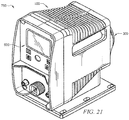
- FIGS. 19-21 Another embodiment of a metering pump (750) is shown in FIGS. 19-21 .
- the metering pump (750) is similar to the metering pump (50) described above, except that the metering pump (750) comprises a digital control panel assembly (600).
- the digital control panel assembly (600) comprises an LCD screen (630) and a keypad (640) positioned on a front surface of the control panel (610).
- the LCD screen (630) can display the selected settings for the pump (750) to a user.
- the LCD screen (630) can be about a 2.4-inch color display, but other suitable configurations can be used.
- the keypad (640) can be used to enable and/or adjust the automatic priming sequence settings.
- the digital control assembly (600) further comprises a power input (602), an external control input (604), and a source tank input (606).
- the power input (602) can be used to couple a power source with the pump (750).
- the external control input (604) can be used to couple an external control with the pump (750) to remotely start/stop and/or pulse the metering pump (750).
- the source tank input (606) can be used to couple the pump (750) with a source tank sensor to detect a low level and/or an empty source tank (2). Accordingly, the pump (750) can automatically stop actuating if there is an insufficient amount of fluid in the source tank (2).
- the metering pump (750) can be incorporated into the metering pump system (10) shown in FIG. 1A . Still other configurations for pump (50, 750) will be apparent to one with ordinary skill in the art in view of the teachings herein.
- a metering pump (50) can be used to transfer fluid from a source tank (2) to a process fluid tank (8) for treatment.
- the diaphragm metering pump (50) generally draws in the fluid from the source tank (2) to an inlet (3) at a first pressure, and discharges the fluid through an outlet (5) at a second pressure.
- the pump (50) creates a negative pressure scenario that lifts the fluid from the source tank (2) into the suction tube (4) toward the inlet (3), or suction end, of the pump (50).
- the pump (50) creates a positive pressure differential to move the fluid towards the outlet (5), or discharge end, of the pump (50).
- the pump (50) is coupled to a pump chamber (60) and a diaphragm (62) is positioned between the pump (50) and the pump chamber (60) such that the diaphragm (62) is aligned with the shaft (420) of the clapper assembly (400).
- the shaft (420) thereby actuates the diaphragm (62) to create a reciprocating motion that leads to pressure changes within the pump chamber (60).
- the pump chamber (60) includes an inlet (3) and an outlet (5).
- the inlet (3) comprises a first check valve (64) and is fluidly coupled to the source tank (2) through suction tubing (4).
- the outlet (5) comprises a second check valve (66) and is fluidly coupled to the process fluid tank (8).
- check valve should be understood to mean a valve having a checking element configured to allow fluid to pass in one direction and arrest fluid flow in an opposing direction.
- first check valve (64) allows fluid to enter the pump chamber (62) from the fluid source (2) during a suction stroke and prevents fluid from exiting through the inlet (3) during a pressure stroke.
- second check valve (66) allows fluid to flow from the pump chamber (60) toward the process fluid tank (8) during a pressure stroke and prevents fluid from being ingested into the pump chamber (60) through outlet (5) during a suction stroke.
- the initial priming sequence of the pump (50) is the process of filling the tubing (4, 6) with fluid such that the pumping system (10) is in an active state prepared to actively inject fluid into the fluid process tank (8).
- this priming process takes several pumping cycles of the pump (50) to fill the tubing (4, 6) adequately prior to being able to inject fluid into the process fluid tank (8), as shown in FIG. 23 .
- the pump (50) may be subject to a loss of prime condition where a portion or all of the tubing (4, 6) is not filled with liquid. This may be caused by evacuated fluid, damaged diaphragms, gassing of the fluid, etc. During a loss of prime condition, the pressure vacuum in the tubing (4, 6) may be lost and the fluid may reverse flow from the tubing (4, 6) back into the source tank (2). This may occur if there is a leak in the system (10), in low duty cycle pumping applications, or if the pump (50) is turned off for an extended amount of time. When prime is lost in the system (10), the system (10) can be re-primed by actuating the pump (50) to return fluid to an adequate level. However, this re-priming may require manual intervention and may be time consuming due to low stroke frequency of the pump (50). This may result in under treating the process fluid because there may be several minutes of appropriate fluid treatment not occurring.
- an automatic prime detection function is provided by monitoring the current of the solenoid assembly (302). For instance, monitoring the current feeding the coil (320) that engages the solenoid assembly (302) may allow for detection of loss of prime. Detection of loss of prime can trigger a priming mode to minimize the time required to re-prime the pumping system (10) and minimize the risk of under-dosing the process fluid. This can also eliminate the need for manual adjustments of the pump (50) to alleviate loss of prime, which is beneficial because typically the system (10) has already been in a prime loss state prior to manual intervention.
- FIG. 24 illustrates an embodiment of a current monitoring circuit (800) that comprises a power source (804), a plurality of gate drivers (802), and a resistor (806).
- Power may be supplied to the circuit (800) by the power source (804).
- This power source (804) may be the same power source that provides power to the pump (50), or it may be a separate power source.
- the power source (804) thereby provides power to the gate drivers (802), which may amplify the current to drive the solenoid assembly (302).
- the current supplied by the current monitoring circuit (800) may be detected by the control panel assembly (500). In the illustrated embodiment, the current is measured between the resistor (806) and the solenoid assembly (302) through an analog-to-digital convertor (506), but other suitable configurations for the current monitoring circuit (800) can be used.
- FIG. 25 An example of a current waveform (900) that may be detected by the current monitoring circuit (800) is shown in FIG. 25 for illustrative purposes.
- This waveform (900) comprises waveform characteristics that may include, but is not limited to, a waveform shape, a period (a), an amplitude (b), noise levels (c, d), and slope (e).
- the waveform (900) comprises a sinusoidal waveform shape with a period of about 20 ms and an amplitude of about 6 A.
- the noise levels (c, d) as shown in FIG. 25 are about 1 A, which can be monitored over time.
- the waveform (900) can have varying shapes, periods, amplitudes, and/or noise levels, and/or other suitable waveform characteristics.
- the circuit (800) can be used to monitor the solenoid current continuously, and/or for selected periods of time.
- the desirable waveform characteristics may be analyzed to determine a characterized or calculated waveform.
- a method (1000) of determining such a characterized waveform is shown in FIG. 26 .
- the current required for the coil (320) to move the solenoid assembly (302) is dependent on the back pressure applied to the diaphragm (62).
- the back pressure applied to the diaphragm (62) and/or solenoid assembly (302) decreases.
- a loss of prime condition and/or a damaged diaphragm (62) may have occurred.
- This selected current value may be repeatable across pumps (50) and may be characterized for comparison purposes.
- the pump (50) may be powered on (1002) and a selected pump load may be set (1004) to operate the solenoid assembly (302) at a desired level.
- the solenoid current can then be measured (1006) using the current monitoring circuit (800) described above.
- any repeatable and/or load dependent waveform characteristics can be identified.
- the measured data can be stored (1008), such as by the control panel assembly (500).
- the waveform characteristics of the solenoid current can then be analyzed. For instance, the waveform shape, period, amplitude, noise levels and/or slope of the waveform can be measured and stored to identify pump scenarios. Different topologies may have different behaviors to identify unloaded scenarios.
- a selected current value for the current to operate the solenoid assembly (302) under normal operating conditions can be determined and stored (1010), such as by the control panel assembly (500).
- a sample of pumps (50) may be used for comparison purposes to characterize a typical waveform for a pump (50). Accordingly, this selected current value can be set based on a selected pump load to operate the solenoid assembly (302) at a desired level, and/or a minimum threshold current can be used as the selected current value to operate the solenoid assembly (302) at a minimum pump load. Still other suitable methods for determining a characterized waveform and/or a selected current value will be apparent to one with ordinary skill in the art in view of the teachings herein.
- a loss of prime condition can then be detected by comparing the measured current to the characterized current such that operation of the pump (50) can be changed based on load.
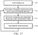
- a method (1100) for detecting such a loss of prime condition is shown in FIG. 27 .
- the pump (50) can power on (1102) and the solenoid current can be measured (1104) using the current monitoring circuit (800) described above.
- the measured current can then be compared to the characterized current (1106).
- the waveform characteristics such as shape, period, amplitude, noise levels, and/or slope, can be compared to determine if the measured current exceeds the selected current value determined by the characterized waveform.
- an example waveform (910) of a loaded pumping system (10) is shown in FIG. 28. Its waveform characteristics, such as waveform shape, period (a), amplitude (b), noise levels (d) and/or slope (e) of the waveform (910) can be measured and stored to identify pump scenarios.
- This loaded waveform (910) may have an amplitude (b) of about 1.5 A and a period (a) of about 300 ms.
- An example waveform (920) of an unloaded pumping system (10) that has lost prime is shown in FIG. 29.
- waveform characteristics such as shape, period (a), amplitude (b), noise levels (d), and/or slope (e)
- This unloaded waveform (920) may have an amplitude (b) of about 1.2 A and a period (a) of about 300 ms. Accordingly, in this example, the amplitude (b) of the unloaded waveform (920) has decreased relative to the amplitude (b) of the loaded waveform (910).
- the noise level (d) and the slope (e) of the unloaded waveform (920) has also increased relative to the noise level (d) and the slope (e) of the loaded waveform (910).
- These waveform changes may thereby indicate a loss of prime condition.
- other suitable changes in the waveform characteristics such as shape, period, amplitude, noise levels, and/or slope, can be used to indicate a loss of prime condition.
- the pump (50) can continue normal operation (1113). If the measured current does not exceed the selected current value, a loss of prime condition may have been detected and the pump (50) may enter a priming mode (1108). Accordingly, in an attempt to re-prime the pumping system (10), the control panel assembly (500) may maximize the stroke speed of the pump (50) for a selected amount of time.
- the pump (50) can be operated at any desirable speed during the priming mode, which can be adjustable. The pump (50) can also enter the priming mode for any selected amount of time, and/or until a primed condition is detected by the circuit (800).
- the present disclosure is directed to an apparatus and method to automatically initiate a priming sequence for a metering pump.
- Metering pumps are typically used to move a specified volume of liquid in a specified time to provide an accurate flow rate.
- Many precision metering pumps use a flexible diaphragm mechanism and checkball configuration to transfer fluid from a source tank to a process fluid tank for treatment.
- the diaphragm and checkball(s) generally create a negative pressure scenario that lifts the fluid from the source tank into the suction tube toward the suction end of the pump.
- the diaphragm and checkball(s) generally create a positive pressure differential to move the fluid towards the discharge end of the pump.
- the amount and speed of fluid movement through the tubing is primarily dependent on the diaphragm displacement during each stroke cycle and the rate of cycling the diaphragm between suction and discharge positions.
- Such metering pumps can pump chemicals, solutions, or other liquids.
- the initial priming sequence of the pump is the process of filling the injection tubing with fluid. Typically, this process takes several pumping cycles to fill the tubing adequately prior to being able to inject fluid into the process fluid tank.
- diaphragm metering pumps may be subject to a loss of prime condition where the tubing is not filled with liquid, and air or gas has built up in the cavity. During a loss of prime condition, the pressure vacuum in the tubing may be lost and the fluid may reverse flow from the tubing back into the source tank. This may particularly occur in low duty cycle pumping applications or if the pump is turned off for an extended amount of time.
- a recurring automatic priming function is provided to maintain the metering pump in a state to actively pump fluid to safeguard against under treatment conditions.
- a method for automatically priming a pump may comprise operating the pump in a priming mode at a priming capacity for a duration period; starting a recurrence timer; operating the pump in its normal operational mode; and operating the pump in the priming mode for the duration period upon expiration of the recurrence timer.
- the method may further comprise resetting the recurrence timer if the pump pumps fluid during its normal operational mode.
- the duration period may selectively adjustable by a duration period timer.
- a recurrence period measured by the recurrence timer may be selectively adjustable.
- the priming capacity may comprise an elevated pump capacity that is higher than the pump capacity in its normal operational mode.
- the priming capacity may comprise a maximum pump capacity of the pump.
- the pump may run at a selected stroke speed during the duration period.
- the pump may run at a selected stroke length during the duration period.
- the pump may be operated in the priming mode when an unprimed condition is sensed.
- the pump may be operated in the priming mode until a primed condition is sensed.
- the pump may be operated in the priming mode when the pump powers on.
- the priming mode may be selectively enabled.
- a pump may comprise an electronic power unit comprising a solenoid assembly and a clapper assembly; a diaphragm coupled to the electronic power unit, wherein the diaphragm is operable to pump fluid when the diaphragm is actuated by the electronic power unit; and a control assembly coupled with the electronic power unit, wherein the control assembly is operable to actuate the electronic power unit; wherein the control assembly is programmed to operate the pump in a priming mode at a priming capacity for a duration period upon expiration of a recurrence timer.
- the control assembly may comprise an external control input, wherein an external control is operable to operate the pump remotely through the external control input.
- the control assembly may comprise a source tank input, wherein the control panel assembly is operable to detect a low level of fluid in a source tank through the source tank input.
- the control assembly may be operable to stop the pump when the low level of fluid is detected in the source tank.
- the control assembly may comprise a keypad operable to input pump settings.
- the control assembly may comprise an LCD screen operable to display the pump settings.
- the pump may be activated to pump fluid from a source tank to a process fluid tank.
- a method for operating a metering pump may comprise activating the pump after a selected amount of time at an elevated capacity for a duration period to pump fluid from a source tank such that the pump is in a primed configuration to actively inject fluid into a process fluid tank.
- Metering pump system (10) for pumping a specified volume of liquid in a specified time includes a storage tank (2), a metering pump (50), and a process fluid tank (8).
- the metering pump (50) is fluidly coupled with the storage tank (2) by suction tubing (4), and the metering pump (50) is fluidly coupled with the process fluid tank (8) by injection tubing (6). Accordingly, the metering pump (50) can be operated to pump fluid from the storage tank (2) to the process fluid tank (8), as shown in FIG. 1B , in a specified time at a desired flow rate.
- the initial priming sequence of the pump (50) is the process of filling the tubing (4, 6) with fluid to a primed condition shown in FIG. 1B .
- this process takes several pumping cycles to fill the tubing (4, 6) adequately prior to being able to inject fluid into the process fluid tank (8).
- any type of metering pump can be incorporated into the metering pump system (10) to pump any type of fluid (i.e., chemicals, solutions, water, etc.), a diaphragm metering pump will be discussed in more detail below.
- FIGS. 2-4 An embodiment of a diaphragm metering pump (50) is shown in FIGS. 2-4 .
- the metering pump (50) comprises a control panel assembly (500) coupled to an electronic power unit (EPU) assembly (300) positioned within a housing (100).
- EPU electronic power unit
- the control panel assembly (500) comprises a printed circuit board (PCB) assembly (520) to selectively control actuation of the pump (50).
- the PCB assembly (520) is coupled to rear surface of a control panel (510) by fasteners (530).
- a pointer (540), a speed control knob (550), a nameplate (570), and a power input (502) are positioned on a front surface of the control panel (510).
- the nameplate (570) in the illustrated embodiment displays adjustable speed settings for the pump (50).
- the pointer (540) and speed control knob (550) are then positioned over the nameplate (570) and coupled to the PCB assembly (520) through the control panel (510) with O-ring (560).
- a user can turn the speed control knob (550) to adjust the speed of the pump (50).
- the pointer (540) is configured to turn with the speed control knob (550) to indicate the selected speed setting on the nameplate (570).
- An opening (504) is also defined by the control panel assembly (500) to allow a user to adjust the stroke length of the pump (50), which will be discussed in more detail below.
- a power source can be connected with the power input (502) of the control panel assembly (500) to provide power to the control panel assembly (500) and/or the EPU assembly (300).
- the pump (50) is battery operated such that the power input (502) is merely optional.
- Other suitable configurations for the control panel assembly (500) will be apparent to one with ordinary skill in the art in view of the teachings herein.
- the housing of the pump (50), as shown in FIGS. 4 and 8-10 , comprises a cover (200) for housing the EPU assembly (300) and is coupled to a rear surface of the control panel assembly (500) by fasteners (120).
- a stroke length adjustment screw (130) is positioned within the opening (504) of the control panel assembly (500) such that threads of the screw (130) correspond to the threads of the opening (504).
- a user can thereby insert a tool, such as a screwdriver, through the opening (504) to turn the screw (130) relative to the control panel assembly (500) to adjust the stroke length of the pump (50).
- a tool such as a screwdriver
- the EPU assembly (300) is coupled with the cover (200) with fasteners (170, 180, 190) and sealed with O-rings (140, 150) and a seal (160) at the rear surface of the cover (200).
- a label (110) can optionally be adhered or coupled to a surface of the housing (100) to provide identifying information for the pump (50).
- Other suitable configurations for the housing (100) will be apparent to one with ordinary skill in the art in view of the teachings herein.
- the EPU assembly (300) comprises a clapper assembly (400) coupled with a solenoid assembly (302).
- the solenoid assembly (302) comprises a coil (320) inserted within a pole piece (330).
- the coil (320) is coupled to the PCB assembly (520) of the control panel assembly (500) by wiring (380).
- the PCB assembly (520) can thereby send pulses of electrical energy to the coil (320) to selectively activate the solenoid assembly (302). For instance, when the coil (320) is activated, it produces a magnetic field that is directed to the clapper assembly (400) by the pole piece (330).
- the solenoid assembly (302) is selectively activated to reciprocate the clapper assembly (400) forward and backward relative to the solenoid assembly (302).
- at least one spring and pad assembly (310) is positioned between the clapper assembly (400) and the solenoid assembly (302) to relieve the impact of the clapper assembly (400) against the solenoid assembly (302).
- a bushing (350) is also positioned around a shaft (420) of the clapper assembly (400) to reduce friction as the clapper assembly (400) translates relative to the solenoid assembly (302).
- the clapper assembly (400) comprises a clapper (410) with a shaft (420) and a spring pin (430) extending outward from a rear surface of the clapper (410).
- the shaft (420) is configured to extend from the housing (100), through an opening of the solenoid assembly (302) and seal (160) of the housing (100).
- the shaft (420) can thereby be reciprocated relative to the solenoid assembly (302) to actuate a diaphragm (62) of the pump (50).
- a ground wire assembly (450) is coupled to the clapper (410) by a fastener (440).
- a first shim (460) is coupled to a front surface of the clapper (410) and a second shim (470) is coupled to a rear surface of the clapper (410) to reduce friction and/or wear of the clapper (410).
- a first shim (460) is coupled to a front surface of the clapper (410) and a second shim (470) is coupled to a rear surface of the clapper (410) to reduce friction and/or wear of the clapper (410).
- the metering pump (50) can be used to transfer fluid from a source tank (2) to a process fluid tank (8) for treatment.
- the diaphragm metering pump (50) generally draws in the fluid from the source tank (2) to an inlet (3) at a first pressure, and discharges the fluid through an outlet (5) at a second pressure.
- the pump (50) creates a negative pressure scenario that lifts the fluid from the source tank (2) into the suction tube (4) toward the inlet (3), or suction end, of the pump (50).
- the pump (50) creates a positive pressure differential to move the fluid towards the outlet (5), or discharge end, of the pump (50).
- the pump (50) is coupled to a pump chamber (60) and a diaphragm (62) is positioned between the pump (50) and the pump chamber (60) such that the diaphragm (62) is aligned with the shaft (420) of the clapper assembly (400).
- the shaft (420) thereby actuates the diaphragm (62) to create a reciprocating motion that leads to pressure changes within the pump chamber (60).
- the pump chamber (60) includes an inlet (3) and an outlet (5).
- the inlet (3) comprises a first check valve (64) and is fluidly coupled to the source tank (2) through suction tubing (4).
- the outlet (5) comprises a second check valve (66) and is fluidly coupled to the process fluid tank (8).
- check valve should be understood to mean a valve having a checking element configured to allow fluid to pass in one direction and arrest fluid flow in an opposing direction.
- first check valve (64) allows fluid to enter the pump chamber (62) from the fluid source (2) during a suction stroke and prevents fluid from exiting through the inlet (3) during a pressure stroke.
- second check valve (66) allows fluid to flow from the pump chamber (60) toward the process fluid tank (8) during a pressure stroke and prevents fluid from being ingested into the pump chamber (60) through outlet (5) during a suction stroke.
- the initial priming sequence of the pump (50) is the process of filling the tubing (4, 6) with fluid such that the pumping system (10) is in an active state prepared to actively inject fluid into the fluid process tank (8).
- this priming process takes several pumping cycles of the pump (50) to fill the tubing (4, 6) adequately prior to being able to inject fluid into the process fluid tank (8), as shown in FIG. 20 .
- the pump (50) may be subject to a loss of prime condition where a portion or all of the tubing (4, 6) is not filled with liquid.
- a loss of prime condition the pressure vacuum in the tubing (4, 6) may be lost and the fluid may reverse flow from the tubing (4, 6) back into the source tank (2). This may particularly occur in low duty cycle pumping applications or if the pump (50) is turned off for an extended amount of time.
- prime is lost in the system (10)
- the system (10) can be re-primed by actuating the pump (50) to return fluid to an adequate level.
- this re-priming may require manual intervention, may be time consuming, and may result in under treating the process fluid.
- a recurring automatic priming function is provided by running the pump (50) for a short duration and periodically thereafter. This may assist in applications where the pump (50) is controlled by a power relay.
- the pump (50) may then return to its set operating mode until the time specified in the recurrence has elapsed.
- the pump (50) may then run again for the set duration and again return to its set operating mode.
- a user can enable and adjust the automatic priming functionality by setting a recurrence schedule and a duration period that is applicable to the characteristics of each pumping system (10).
- This automatic priming sequence is also more efficient because there is no time delay in waiting for the pump (50) to regain prime and there is no under treatment of the process fluid.
- Such an automatic priming sequence can also be incorporated on a metering pump, such as a metering pump (750) shown in FIGS. 21-23 .
- the metering pump (750) is similar to the metering pump (50) described above, except that the metering pump (750) comprises a digital control panel assembly (600).
- the digital control panel assembly (600) comprises an LCD screen (630) and a keypad (640) positioned on a front surface of the control panel (610).
- the LCD screen (630) can display the selected settings for the pump (750) to a user.
- the LCD screen (630) can be about a 2.4-inch color display, but other suitable configurations can be used.
- the keypad (640) can be used to enable and/or adjust the automatic priming sequence settings.
- the digital control assembly (600) further comprises a power input (602), an external control input (604), and a source tank input (606).
- the power input (602) can be used to couple a power source with the pump (750).
- the external control input (604) can be used to couple an external control with the pump (750) to remotely start/stop and/or pulse the metering pump (750).
- the source tank input (606) can be used to couple the pump (750) with a source tank sensor to detect a low level and/or an empty source tank (2). Accordingly, the pump (750) can automatically stop actuating if there is an insufficient amount of fluid in the source tank (2).
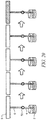
- FIG. 24 an input-output schematic of the pump (750) is shown in FIG. 24 .
- a power source (18) can be coupled with the power input (602) of the pump (750) to supply power to the control panel assembly (600) and/or the EPU assembly (350).
- the power source (18) can supply between about 85 and about 265 Volts.
- the control panel assembly (600) can then selectively actuate the EPU assembly (300) to control the pump (750).
- the pump (750) is thereby operable to pump fluid from the source tank (2) to the process fluid tank (8).
- a user can input and/or adjust desired settings for the pump (750) through the keypad (640) of the control panel assembly (600).
- the screen (630) of the control panel assembly (600) can then display the selected settings of the pump (750) to the user.
- An external control (14) can be coupled with the external control input (604) of the pump (750) to provide a remote start/stop and/or pulse control of the pump (750).
- An empty tank sensor (16) and/or a lower level tank sensor (17) can be coupled with the source tank input (606) of the pump (750) to detect a low level and/or an empty source tank (2), which can automatically stop actuating the pump (750) if there is an insufficient amount of fluid in the source tank (2).
- a flow meter (12) can also be coupled with the pump (750) to measure the flow rate of the pump (750).
- the pump (750) provides about a 24V output to the flow meter (12), the external control (14), the sensors (16, 17), and/or any combination thereof.
- Other suitable configurations for operating the pump (750) will be apparent to one with ordinary skill in the art in view of the teachings herein.
- the automatic priming sequence can be enabled and/or configured on the metering pump (750).
- FIGS. 25-26 show the LCD screen (630) of the control panel assembly (600) with an embodiment of a menu screen (639a) and an automatic priming sequence screen (639b) for illustrative purposes.
- the menu screen (639a) of FIG. 25 displays an automatic priming system icon (631) that can be adjusted to enable and/or disable the automatic priming sequence.
- the automatic priming sequence is disabled by default.
- the menu screen (639a) further comprises a pump capacity icon (633) that can be adjusted to select a desired operating pump capacity.
- the pump capacity is set to a maximum pump capacity at 100%.
- the pump (750) can run at any desired priming capacity, such as at a maximum capacity, an elevated capacity higher than its normal operating capacity, its normal operating capacity, a lower capacity than its normal operating capacity, or any combination thereof.
- This pump capacity setting is confirmed in the pump capacity setting display (632).
- a user can adjust the pump settings using the keypad (640), which may include push button controls to start and/or stop the pump (750), select a desired speed for the pump (750), display a settings menu for the pump (750), and/or an enter button to select the settings for the pump (750).
- the pump speed can be adjusted from between about 0 and about 220 strokes per minute, and the performance range of the pump can be adjusted to pump between about 0 and about 2.5 gallons per hour at between about 0 and about 250 psi.
- the LCD screen (630) can further display alert and/or alarm notifications, the flow rate, the stroke speed, and/or the percent capacity of the pump (750) to the user.
- the menu can provide options for a user to select a manual mode, a pulse mode, calibration, units of measure, totalizer, and/or automated priming of the pump (750). Of course, other suitable configurations for adjusting the pump settings can be used.
- FIG. 26 An embodiment of the LCD screen (630) for displaying and/or adjusting the automatic priming settings is shown in FIG. 26 .
- the selected recurrence schedule is displayed with the recurrence schedule icon (635) to show that the recurrence timer (636) is set to 120 minutes.
- the control panel assembly (600) can be used to adjust this recurrence timer (636) to any desirable amount of time.
- the duration period is displayed with the duration period icon (637) to show that the duration period (638) is set to 20 seconds.
- the control panel assembly (600) can also be used to adjust this duration period to any desirable amount of time.
- the digital control panel assembly (600) can activate the pump (750) to run in a priming configuration at maximum capacity for 20 seconds every 120 minutes to maintain the pump (750) in a primed condition.
- This feature may run the pump (750) as long as the pump (750) is in the running state, even if the pump (750) is in manual mode with the stroke rate set to 0%, or in external pulse mode with no incoming pulses.
- Other suitable configurations for adjusting these settings will be apparent to one with ordinary skill in the art in view of the teachings herein.
- such an automatic priming sequence comprises powering the pump on (710) and running the pump (750) for a selected duration period (712).
- a user can select a desired amount of time to run the pump (750) and/or select a desired capacity at which to run the pump (750) to drive fluid into the tubing (4, 6) of the pumping system (10).
- the pump (750) can run at any desired priming capacity during this duration period, such as at a maximum capacity, an elevated capacity higher than its normal operating capacity, its normal operating capacity, a lower capacity than its normal operating capacity, or any combination thereof.
- the amount of time for the duration period and/or the pump capacity can be adjustable. In some instances, the stroke speed and/or the stroke length can be adjusted for a desired priming configuration.
- the pump (750) can be set to its configured operating mode (714) for normal operation of the pump (750).
- the system (10) can automatically repeat running the pump (750) for the selected duration period (712) at the selected pump capacity.
- the recurrence schedule can also be adjustable. This initiation of an automatic priming system can easily and more efficiently maintain the pump in a primed configuration.
- Such control of the pump (750) can be provided by the control panel assembly (600).
- Other suitable configurations for automatically initiating the priming sequence of the pump (750) will be apparent to one with ordinary skill in the art in view of the teachings herein.
- additional fluid may be pumped into the process fluid tank (8) after running the automated priming sequence if there was already fluid in the tubing (4, 6).
- the pump system (10) can be used to detect a loss of prime condition to activate the automatic priming sequence in addition to or instead of the recurrence timer.
- An example for detecting a loss of prime condition is described in U.S. Patent Application Serial No. TBD, entitled Solenoid Current Monitoring Method for Leak Detection and Vapor Lock, filed on TBD, the disclosure of which is incorporated by reference herein.
- the pump system (10) can be used to detect that the system (10) is primed to automatically end the priming sequence in addition to or instead of the duration period timer.
- a sensor may be placed in the tubing (4, 6) to detect fluid in the tubing (4,6) to thereby indicate that the pump (750) is primed.
- the measured current can again be compared to determine whether the measured current exceeds the selected current value (1110). If the measured current does exceed the selected current value such that the pumping system (10) has regained prime, the pump (50) can revert back to the pre-programmed stroke speed and continue normal operation (1113). If after the priming mode, the back pressure has not increased such that the measured current does not exceed the selected current value, the pump (50) may be operated in an alert mode where the pump may be stopped and/or a warning may be issued that a loss of prime condition has occurred (1112). Because an attempt to re-prime the system (10) has failed, the loss of prime condition may be due to a damaged diaphragm. Still other suitable methods for detecting a loss of prime condition will be apparent to one with ordinary skill in the art in view of the teachings herein.
Abstract
Description
- The present disclosure is directed to an apparatus and method to detect a loss of prime condition for a metering pump.
- Metering pumps are typically used to move a specified volume of liquid in a specified time to provide an accurate flow rate. Many precision metering pumps use a flexible diaphragm mechanism and checkball configuration to transfer fluid from a source tank to a process fluid tank for treatment. During a suction stroke, the diaphragm and checkball(s) generally create a negative pressure scenario that lifts the fluid from the source tank into the suction tube toward the suction end of the pump. During the discharge stroke, the diaphragm and checkball(s) generally create a positive pressure differential to move the fluid towards the discharge end of the pump. The amount and speed of fluid movement through the tubing is primarily dependent on the diaphragm displacement during each stroke cycle and the rate of cycling the diaphragm between suction and discharge positions. Such metering pumps can pump chemicals, solutions, or other liquids.
- The initial priming sequence of the pump is the process of filling the injection tubing with fluid. Typically, this process takes several pumping cycles to fill the tubing adequately prior to being able to inject fluid into the process fluid tank. In some instances, diaphragm metering pumps may be subject to a loss of prime condition where the tubing is not filled with liquid, and air or gas has built up in the cavity. During a loss of prime condition, the pressure vacuum in the tubing may be lost and the fluid may reverse flow from the tubing back into the source tank. This may particularly occur in low duty cycle pumping applications or if the pump is turned off for an extended amount of time. When prime is lost in the system, the air can be removed and replaced with liquid to re-prime the system through suction/discharge strokes of the metering pump. However, this re-priming requires manual intervention, and may be time consuming and may result in under treating the process fluid. Accordingly, there is a need to provide an easier and more efficient method to detect a loss of prime condition for metering pumps.
- A priming detection function is provided to determine whether the metering pump is in a state to actively pump fluid to safeguard against under treatment conditions.
- In one embodiment, a method for detecting a loss of prime condition in a pumping system may comprise characterizing at least one waveform characteristic of the current to a solenoid assembly that actuates a pump of the pumping system; determining a selected current value needed to operate the solenoid assembly based on the characterized waveform; measuring a current to the solenoid assembly; and comparing the measured current to the selected current value. The at least one waveform characteristic may comprise one or more of a shape, an amplitude, a period, a noise level, and a slope of the measured current. Characterizing the at least one waveform characteristic may comprise: setting a selected pump load to operate the solenoid assembly at a desired level; measuring the current to the solenoid assembly to determine a selected current value; and storing the measured data in a control assembly. A loss of prime condition may be detected when the measured current is below the selected current value. The pump may initiate a priming mode when the loss of prime condition is detected. The priming mode may comprise actuating the pump at an elevated speed for a selected amount of time. The pump may be operated in an alert mode when the loss of prime condition is detected by selecting one or more of stopping the pump and issuing a warning that the loss of prime condition has occurred. The pump may continue normal operation when the measured current is at or above the selected current value.
- In another embodiment, a method for operating a pump that comprises a solenoid assembly for actuating the pump may comprise: measuring a current of the solenoid assembly; determining whether the measured current exceeds a selected current value; and operating the pump based on whether the measured current exceeds the selected current value. The pump may continue normal operation of the pump if the measured current exceeds the selected current value. The pump may initiate a priming mode if the measured current does not exceed the selected current value. It may be determined whether the measured current exceeds the selected current value after operating the pump in the priming mode. The pump may revert to normal operation if the measured current exceeds the selected current value after operating the pump in the priming mode. The pump may initiate an alert mode if the measured current does not exceed the selected current value after operating the pump in the priming mode by selecting one or more of stopping the pump and issuing a warning that the loss of prime condition has occurred.
- In another embodiment, a pumping system may comprise: an electronic power unit comprising a solenoid assembly and a clapper assembly; a diaphragm coupled to the electronic power unit, wherein the diaphragm is operable to pump fluid when the diaphragm is actuated by the electronic power unit; and a control assembly coupled with the electronic power unit, wherein the control assembly is operable to actuate the electronic power unit; wherein the control assembly is programmed to detect a loss of prime condition in the pumping system by measuring a current to the solenoid assembly. The control assembly may be programmed to detect the loss of prime condition by comparing the measured current to a selected current value needed to actuate the solenoid assembly. The control assembly may be programmed to actuate the pump based on whether the loss of prime condition is detected. The control assembly may be programmed to actuate the pump at a maximum capacity when the loss of prime condition is detected. A current monitoring circuit may be operable to measure the current to the solenoid assembly. The current monitoring circuit may comprise a resistor, wherein the monitoring circuit is operable to measure the current supplied to the solenoid assembly through the resistor.
- The foregoing has outlined rather broadly the features and technical advantages of the present invention in order that the detailed description of the invention that follows may be better understood. Additional features and advantages of the invention will be described hereinafter which form the subject of the claims of the invention. It should be appreciated by those skilled in the art that the conception and specific embodiment disclosed may be readily utilized as a basis for modifying or designing other structures for carrying out the same purposes of the present invention. It should also be realized by those skilled in the art that such equivalent constructions do not depart from the spirit and scope of the invention as set forth in the appended claims. The novel features which are believed to be characteristic of the invention, both as to its organization and method of operation, together with further objects and advantages will be better understood from the following description when considered in connection with the accompanying figures. It is to be expressly understood, however, that each of the figures is provided for the purpose of illustration and description only and is not intended as a definition of the limits of the present invention.
- For a more complete understanding of the present invention, reference is now made to the following descriptions taken in conjunction with the accompanying drawings, in which:
-
FIG. 1A depicts a schematic of a metering pump system. -
FIG. 1B depicts a schematic of the metering pump system ofFIG. 1 in a primed configuration. -
FIG. 2 depicts a top perspective view of a metering pump of the metering pump system ofFIG. 1A . -
FIG. 3 depicts a front view of the metering pump ofFIG. 2 . -
FIG. 4 depicts a cross-sectional view of the metering pump ofFIG. 2 taken along line 4-4 ofFIG. 3 . -
FIG. 5 depicts an exploded view of a control panel assembly of the metering pump ofFIG. 2 . -
FIG. 6 depicts a front view of the control panel assembly ofFIG. 5 . -
FIG. 7 depicts a cross-sectional view of the control panel assembly ofFIG. 5 taken along line 7-7 ofFIG. 6 . -
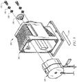
FIG. 8 depicts an exploded view of a housing assembly of the metering pump ofFIG. 2 , with an electronic power unit (EPU) assembly removed. -
FIG. 9 depicts a front view of the housing assembly ofFIG. 8 , with the EPU assembly assembled with the housing assembly. -
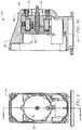
FIG. 10 depicts a cross-sectional view of the housing assembly ofFIG. 8 taken along line 10-10 ofFIG. 9 , with the EPU assembly assembled with the housing assembly. -
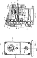
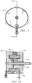
FIG. 11 depicts a top perspective view of the EPU assembly ofFIG. 8 . -
FIG. 12 depicts an exploded view of a solenoid assembly of the EPU assembly ofFIG. 8 , with a clapper assembly removed. -
FIG. 13 depicts a front view of the EPU assembly ofFIG. 8 . -
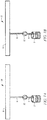
FIG. 14 depicts a cross-sectional view of the EPU assembly ofFIG. 8 taken along line 14-14 ofFIG. 13 . -
FIG. 15 depicts a rear perspective view of the clapper assemblyFIG. 12 . -
FIG. 16 depicts a front exploded view of the clapper assembly ofFIG. 15 . -
FIG. 17 depicts a front view of the clapper assembly ofFIG. 15 . -
FIG. 18 depicts a cross-sectional view of the clapper assembly ofFIG. 15 taken along line 18-18 ofFIG. 17 . -
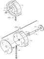
FIG. 19 depicts a top perspective view of another metering pump that can be incorporated with the metering pump system ofFIG. 1A . -
FIG. 20 depicts a front view of the metering pump ofFIG. 19 . -
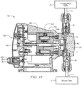
FIG. 21 depicts a cross-sectional view of the metering pump ofFIG. 19 taken along line 21-21 ofFIG. 20 . -
FIG. 22 depicts a cross-sectional view of the metering pump system ofFIG. 1A . -
FIG. 23 depicts a schematic of a priming sequence of the metering pump system ofFIG. 1A . -
FIG. 24 depicts a schematic of a current monitoring circuit for use with the metering pump system ofFIG. 1A . -
FIG. 25 depicts a diagram of a motor current waveform that may be detected by the current monitoring circuit ofFIG. 24 . -
FIG. 26 depicts a schematic of a motor current comparison sequence for use with the metering pump system ofFIG. 1A . -
FIG. 27 depicts a schematic of a pump priming detection sequence for use with the metering pump system ofFIG. 1A . - FIG. 28 depicts a diagram of a loaded current waveform that may be detected by the current monitoring circuit of
FIG. 24 . - FIG. 29 depicts a diagram of an unloaded current waveform that may be detected by the current monitoring circuit of
FIG. 24 . - Referring now to
Figure 1A , an exemplary system using a metering pump is described. Metering pump system (10) for pumping a specified volume of liquid in a specified time includes a storage tank (2), a metering pump (50), and a process fluid tank (8). The metering pump (50) is fluidly coupled with the storage tank (2) by suction tubing (4), and the metering pump (50) is fluidly coupled with the process fluid tank (8) by injection tubing (6). Accordingly, the metering pump (50) can be operated to pump fluid from the storage tank (2) to the process fluid tank (8), as shown inFIG. 1B , in a specified time at a desired flow rate. The initial priming sequence of the pump (50) is the process of filling the tubing (4, 6) with fluid to a primed condition shown in FIG. IB. Typically, this process takes several pumping cycles to fill the tubing (4, 6) adequately prior to being able to inject fluid into the process fluid tank (8). Although any type of metering pump can be incorporated into the metering pump system (10) to pump any type of fluid (i.e., chemicals, solutions, water, etc.), a diaphragm metering pump will be discussed in more detail below. - An embodiment of a diaphragm metering pump (50) is shown in
FIGS. 2-4 . In the illustrated embodiment, the metering pump (50) comprises a control panel assembly (500) coupled to an electronic power unit (EPU) assembly (300) positioned within a housing (100). Each of these components will be described in more detail below. - As best seen in
FIGS. 5-7 , the control panel assembly (500) comprises a printed circuit board (PCB) assembly (520) to selectively control actuation of the pump (50). The PCB assembly (520) is coupled to rear surface of a control panel (510) by fasteners (530). A pointer (540), a speed control knob (550), a nameplate (570), and a power input (502) are positioned on a front surface of the control panel (510). The nameplate (570) in the illustrated embodiment displays adjustable speed settings for the pump (50). The pointer (540) and speed control knob (550) are then positioned over the nameplate (570) and coupled to the PCB assembly (520) through the control panel (510) with O-ring (560). Accordingly, a user can turn the speed control knob (550) to adjust the speed of the pump (50). The pointer (540) is configured to turn with the speed control knob (550) to indicate the selected speed setting on the nameplate (570). Still other suitable configurations for adjusting the speed of the pump (50) will be apparent to one with ordinary skill in the art in view of the teachings herein. An opening (504) is also defined by the control panel assembly (500) to allow a user to adjust the stroke length of the pump (50), which will be discussed in more detail below. A power source can be connected with the power input (502) of the control panel assembly (500) to provide power to the control panel assembly (500) and/or the EPU assembly (300). In some instances, the pump (50) is battery operated such that the power input (502) is merely optional. Other suitable configurations for the control panel assembly (500) will be apparent to one with ordinary skill in the art in view of the teachings herein. - The housing of the pump (50), as shown in
FIGS. 4 and8-10 , comprises a cover (200) for housing the EPU assembly (300) and is coupled to a rear surface of the control panel assembly (500) by fasteners (120). A stroke length adjustment screw (130) is positioned within the opening (504) of the control panel assembly (500) such that threads of the screw (130) correspond to the threads of the opening (504). A user can thereby insert a tool, such as a screwdriver, through the opening (504) to turn the screw (130) relative to the control panel assembly (500) to adjust the stroke length of the pump (50). Still other suitable configurations for adjusting the stroke length will be apparent to one with ordinary skill in the art in view of the teachings herein. The EPU assembly (300) is coupled with the cover (200) with fasteners (170, 180, 190) and sealed with O-rings (140, 150) and a seal (160) at the rear surface of the cover (200). A label (110) can optionally be adhered or coupled to a surface of the housing (100) to provide identifying information for the pump (50). Other suitable configurations for the housing (100) will be apparent to one with ordinary skill in the art in view of the teachings herein. - Referring to
FIGS. 11-14 , the EPU assembly (300) comprises a clapper assembly (400) coupled with a solenoid assembly (302). The solenoid assembly (302) comprises a coil (320) inserted within a pole piece (330). The coil (320) is coupled to the PCB assembly (520) of the control panel assembly (500) by wiring (380). The PCB assembly (520) can thereby send pulses of electrical energy to the coil (320) to selectively activate the solenoid assembly (302). For instance, when the coil (320) is activated, it produces a magnetic field that is directed to the clapper assembly (400) by the pole piece (330). Accordingly, the solenoid assembly (302) is selectively activated to reciprocate the clapper assembly (400) forward and backward relative to the solenoid assembly (302). In the illustrated embodiment, at least one spring and pad assembly (310) is positioned between the clapper assembly (400) and the solenoid assembly (302) to relieve the impact of the clapper assembly (400) against the solenoid assembly (302). A bushing (350) is also positioned around a shaft (420) of the clapper assembly (400) to reduce friction as the clapper assembly (400) translates relative to the solenoid assembly (302). - The clapper assembly (400), as best seen in
FIGS. 15-18 , comprises a clapper (410) with a shaft (420) and a spring pin (430) extending outward from a rear surface of the clapper (410). The shaft (420) is configured to extend from the housing (100), through an opening of the solenoid assembly (302) and seal (160) of the housing (100). The shaft (420) can thereby be reciprocated relative to the solenoid assembly (302) to actuate a diaphragm (62) of the pump (50). A ground wire assembly (450) is coupled to the clapper (410) by a fastener (440). A first shim (460) is coupled to a front surface of the clapper (410) and a second shim (470) is coupled to a rear surface of the clapper (410) to reduce friction and/or wear of the clapper (410). Still other suitable configurations for the EPU assembly (300) will be apparent to one with ordinary skill in the art in view of the teachings herein. - Another embodiment of a metering pump (750) is shown in
FIGS. 19-21 . The metering pump (750) is similar to the metering pump (50) described above, except that the metering pump (750) comprises a digital control panel assembly (600). As best seen inFIG. 20 , the digital control panel assembly (600) comprises an LCD screen (630) and a keypad (640) positioned on a front surface of the control panel (610). The LCD screen (630) can display the selected settings for the pump (750) to a user. The LCD screen (630) can be about a 2.4-inch color display, but other suitable configurations can be used. The keypad (640) can be used to enable and/or adjust the automatic priming sequence settings. The digital control assembly (600) further comprises a power input (602), an external control input (604), and a source tank input (606). The power input (602) can be used to couple a power source with the pump (750). The external control input (604) can be used to couple an external control with the pump (750) to remotely start/stop and/or pulse the metering pump (750). The source tank input (606) can be used to couple the pump (750) with a source tank sensor to detect a low level and/or an empty source tank (2). Accordingly, the pump (750) can automatically stop actuating if there is an insufficient amount of fluid in the source tank (2). The metering pump (750) can be incorporated into the metering pump system (10) shown inFIG. 1A . Still other configurations for pump (50, 750) will be apparent to one with ordinary skill in the art in view of the teachings herein. - As discussed above, a metering pump (50) can be used to transfer fluid from a source tank (2) to a process fluid tank (8) for treatment. Referring to
FIG. 22 , the diaphragm metering pump (50) generally draws in the fluid from the source tank (2) to an inlet (3) at a first pressure, and discharges the fluid through an outlet (5) at a second pressure. During a suction stroke, the pump (50) creates a negative pressure scenario that lifts the fluid from the source tank (2) into the suction tube (4) toward the inlet (3), or suction end, of the pump (50). During the discharge stroke, the pump (50) creates a positive pressure differential to move the fluid towards the outlet (5), or discharge end, of the pump (50). - In the illustrated embodiment, the pump (50) is coupled to a pump chamber (60) and a diaphragm (62) is positioned between the pump (50) and the pump chamber (60) such that the diaphragm (62) is aligned with the shaft (420) of the clapper assembly (400). The shaft (420) thereby actuates the diaphragm (62) to create a reciprocating motion that leads to pressure changes within the pump chamber (60). The pump chamber (60) includes an inlet (3) and an outlet (5). The inlet (3) comprises a first check valve (64) and is fluidly coupled to the source tank (2) through suction tubing (4). The outlet (5) comprises a second check valve (66) and is fluidly coupled to the process fluid tank (8). The term "check valve" should be understood to mean a valve having a checking element configured to allow fluid to pass in one direction and arrest fluid flow in an opposing direction. Accordingly, the first check valve (64) allows fluid to enter the pump chamber (62) from the fluid source (2) during a suction stroke and prevents fluid from exiting through the inlet (3) during a pressure stroke. The second check valve (66) allows fluid to flow from the pump chamber (60) toward the process fluid tank (8) during a pressure stroke and prevents fluid from being ingested into the pump chamber (60) through outlet (5) during a suction stroke.
- The initial priming sequence of the pump (50) is the process of filling the tubing (4, 6) with fluid such that the pumping system (10) is in an active state prepared to actively inject fluid into the fluid process tank (8). Typically, this priming process takes several pumping cycles of the pump (50) to fill the tubing (4, 6) adequately prior to being able to inject fluid into the process fluid tank (8), as shown in
FIG. 23 . - In some instances, the pump (50) may be subject to a loss of prime condition where a portion or all of the tubing (4, 6) is not filled with liquid. This may be caused by evacuated fluid, damaged diaphragms, gassing of the fluid, etc. During a loss of prime condition, the pressure vacuum in the tubing (4, 6) may be lost and the fluid may reverse flow from the tubing (4, 6) back into the source tank (2). This may occur if there is a leak in the system (10), in low duty cycle pumping applications, or if the pump (50) is turned off for an extended amount of time. When prime is lost in the system (10), the system (10) can be re-primed by actuating the pump (50) to return fluid to an adequate level. However, this re-priming may require manual intervention and may be time consuming due to low stroke frequency of the pump (50). This may result in under treating the process fluid because there may be several minutes of appropriate fluid treatment not occurring.
- Because it may be desirable to maintain fluid in the tubing (4, 6) of the pumping system (10) such that the pump (50) is in a primed condition, an automatic prime detection function is provided by monitoring the current of the solenoid assembly (302). For instance, monitoring the current feeding the coil (320) that engages the solenoid assembly (302) may allow for detection of loss of prime. Detection of loss of prime can trigger a priming mode to minimize the time required to re-prime the pumping system (10) and minimize the risk of under-dosing the process fluid. This can also eliminate the need for manual adjustments of the pump (50) to alleviate loss of prime, which is beneficial because typically the system (10) has already been in a prime loss state prior to manual intervention.
-
FIG. 24 illustrates an embodiment of a current monitoring circuit (800) that comprises a power source (804), a plurality of gate drivers (802), and a resistor (806). Power may be supplied to the circuit (800) by the power source (804). This power source (804) may be the same power source that provides power to the pump (50), or it may be a separate power source. The power source (804) thereby provides power to the gate drivers (802), which may amplify the current to drive the solenoid assembly (302). The current supplied by the current monitoring circuit (800) may be detected by the control panel assembly (500). In the illustrated embodiment, the current is measured between the resistor (806) and the solenoid assembly (302) through an analog-to-digital convertor (506), but other suitable configurations for the current monitoring circuit (800) can be used. - An example of a current waveform (900) that may be detected by the current monitoring circuit (800) is shown in
FIG. 25 for illustrative purposes. This waveform (900) comprises waveform characteristics that may include, but is not limited to, a waveform shape, a period (a), an amplitude (b), noise levels (c, d), and slope (e). In the illustrated embodiment, the waveform (900) comprises a sinusoidal waveform shape with a period of about 20 ms and an amplitude of about 6 A. The noise levels (c, d) as shown inFIG. 25 are about 1 A, which can be monitored over time. Of course, the waveform (900) can have varying shapes, periods, amplitudes, and/or noise levels, and/or other suitable waveform characteristics. The circuit (800) can be used to monitor the solenoid current continuously, and/or for selected periods of time. - Once the current waveform (900) is detected by the circuit (800), the desirable waveform characteristics may be analyzed to determine a characterized or calculated waveform. A method (1000) of determining such a characterized waveform is shown in
FIG. 26 . For instance, the current required for the coil (320) to move the solenoid assembly (302) is dependent on the back pressure applied to the diaphragm (62). As liquid is evacuated from the pump end and replaced with air, resulting in a loss of prime condition, the back pressure applied to the diaphragm (62) and/or solenoid assembly (302) decreases. Below a desired threshold, a loss of prime condition and/or a damaged diaphragm (62) may have occurred. This selected current value may be repeatable across pumps (50) and may be characterized for comparison purposes. - Referring to
FIG. 26 , to characterize the selected current value, the pump (50) may be powered on (1002) and a selected pump load may be set (1004) to operate the solenoid assembly (302) at a desired level. The solenoid current can then be measured (1006) using the current monitoring circuit (800) described above. By monitoring the solenoid current, any repeatable and/or load dependent waveform characteristics can be identified. The measured data can be stored (1008), such as by the control panel assembly (500). The waveform characteristics of the solenoid current can then be analyzed. For instance, the waveform shape, period, amplitude, noise levels and/or slope of the waveform can be measured and stored to identify pump scenarios. Different topologies may have different behaviors to identify unloaded scenarios. From the monitored waveforms, a selected current value for the current to operate the solenoid assembly (302) under normal operating conditions can be determined and stored (1010), such as by the control panel assembly (500). A sample of pumps (50) may be used for comparison purposes to characterize a typical waveform for a pump (50). Accordingly, this selected current value can be set based on a selected pump load to operate the solenoid assembly (302) at a desired level, and/or a minimum threshold current can be used as the selected current value to operate the solenoid assembly (302) at a minimum pump load. Still other suitable methods for determining a characterized waveform and/or a selected current value will be apparent to one with ordinary skill in the art in view of the teachings herein. - A loss of prime condition can then be detected by comparing the measured current to the characterized current such that operation of the pump (50) can be changed based on load. A method (1100) for detecting such a loss of prime condition is shown in
FIG. 27 . The pump (50) can power on (1102) and the solenoid current can be measured (1104) using the current monitoring circuit (800) described above. The measured current can then be compared to the characterized current (1106). For instance, the waveform characteristics, such as shape, period, amplitude, noise levels, and/or slope, can be compared to determine if the measured current exceeds the selected current value determined by the characterized waveform. - For instance, an example waveform (910) of a loaded pumping system (10) is shown in FIG. 28. Its waveform characteristics, such as waveform shape, period (a), amplitude (b), noise levels (d) and/or slope (e) of the waveform (910) can be measured and stored to identify pump scenarios. This loaded waveform (910) may have an amplitude (b) of about 1.5 A and a period (a) of about 300 ms. An example waveform (920) of an unloaded pumping system (10) that has lost prime is shown in FIG. 29. Its waveform characteristics, such as shape, period (a), amplitude (b), noise levels (d), and/or slope (e), can then be compared to determine if the measured current exceeds the selected current value determined by the characterized waveform based on the loaded waveform (910). This unloaded waveform (920) may have an amplitude (b) of about 1.2 A and a period (a) of about 300 ms. Accordingly, in this example, the amplitude (b) of the unloaded waveform (920) has decreased relative to the amplitude (b) of the loaded waveform (910). The noise level (d) and the slope (e) of the unloaded waveform (920) has also increased relative to the noise level (d) and the slope (e) of the loaded waveform (910). These waveform changes may thereby indicate a loss of prime condition. Of course, other suitable changes in the waveform characteristics, such as shape, period, amplitude, noise levels, and/or slope, can be used to indicate a loss of prime condition.
- Referring back to
FIG. 27 , if the measured current does exceed the selected current value, the pump (50) can continue normal operation (1113). If the measured current does not exceed the selected current value, a loss of prime condition may have been detected and the pump (50) may enter a priming mode (1108). Accordingly, in an attempt to re-prime the pumping system (10), the control panel assembly (500) may maximize the stroke speed of the pump (50) for a selected amount of time. Of course, other suitable priming modes can be used. For instance, the pump (50) can be operated at any desirable speed during the priming mode, which can be adjustable. The pump (50) can also enter the priming mode for any selected amount of time, and/or until a primed condition is detected by the circuit (800). Further examples of such priming modes are described inU.S. Patent Application Serial No. 15/824,682 - This application claims the benefit of
U.S. Provisional Patent Application No. 62/558,476, filed September 14, 2017 - The present disclosure is directed to an apparatus and method to automatically initiate a priming sequence for a metering pump.
- Metering pumps are typically used to move a specified volume of liquid in a specified time to provide an accurate flow rate. Many precision metering pumps use a flexible diaphragm mechanism and checkball configuration to transfer fluid from a source tank to a process fluid tank for treatment. During a suction stroke, the diaphragm and checkball(s) generally create a negative pressure scenario that lifts the fluid from the source tank into the suction tube toward the suction end of the pump. During the discharge stroke, the diaphragm and checkball(s) generally create a positive pressure differential to move the fluid towards the discharge end of the pump. The amount and speed of fluid movement through the tubing is primarily dependent on the diaphragm displacement during each stroke cycle and the rate of cycling the diaphragm between suction and discharge positions. Such metering pumps can pump chemicals, solutions, or other liquids.
- The initial priming sequence of the pump is the process of filling the injection tubing with fluid. Typically, this process takes several pumping cycles to fill the tubing adequately prior to being able to inject fluid into the process fluid tank. In some instances, diaphragm metering pumps may be subject to a loss of prime condition where the tubing is not filled with liquid, and air or gas has built up in the cavity. During a loss of prime condition, the pressure vacuum in the tubing may be lost and the fluid may reverse flow from the tubing back into the source tank. This may particularly occur in low duty cycle pumping applications or if the pump is turned off for an extended amount of time. When prime is lost in the system, the air can be removed and replaced with liquid to re-prime the system through suction/discharge strokes of the metering pump. However, this re-priming requires manual intervention, and may be time consuming and may result in under treating the process fluid. Accordingly, there is a need to provide an easier and more efficient priming sequence for metering pumps.
- A recurring automatic priming function is provided to maintain the metering pump in a state to actively pump fluid to safeguard against under treatment conditions.
- In one embodiment, a method for automatically priming a pump may comprise operating the pump in a priming mode at a priming capacity for a duration period; starting a recurrence timer; operating the pump in its normal operational mode; and operating the pump in the priming mode for the duration period upon expiration of the recurrence timer. The method may further comprise resetting the recurrence timer if the pump pumps fluid during its normal operational mode. The duration period may selectively adjustable by a duration period timer. A recurrence period measured by the recurrence timer may be selectively adjustable. The priming capacity may comprise an elevated pump capacity that is higher than the pump capacity in its normal operational mode. The priming capacity may comprise a maximum pump capacity of the pump. The pump may run at a selected stroke speed during the duration period. The pump may run at a selected stroke length during the duration period. The pump may be operated in the priming mode when an unprimed condition is sensed. The pump may be operated in the priming mode until a primed condition is sensed. The pump may be operated in the priming mode when the pump powers on. The priming mode may be selectively enabled.
- In another embodiment, a pump may comprise an electronic power unit comprising a solenoid assembly and a clapper assembly; a diaphragm coupled to the electronic power unit, wherein the diaphragm is operable to pump fluid when the diaphragm is actuated by the electronic power unit; and a control assembly coupled with the electronic power unit, wherein the control assembly is operable to actuate the electronic power unit; wherein the control assembly is programmed to operate the pump in a priming mode at a priming capacity for a duration period upon expiration of a recurrence timer. The control assembly may comprise an external control input, wherein an external control is operable to operate the pump remotely through the external control input. The control assembly may comprise a source tank input, wherein the control panel assembly is operable to detect a low level of fluid in a source tank through the source tank input. The control assembly may be operable to stop the pump when the low level of fluid is detected in the source tank. The control assembly may comprise a keypad operable to input pump settings. The control assembly may comprise an LCD screen operable to display the pump settings. The pump may be activated to pump fluid from a source tank to a process fluid tank.
- In another embodiment, a method for operating a metering pump may comprise activating the pump after a selected amount of time at an elevated capacity for a duration period to pump fluid from a source tank such that the pump is in a primed configuration to actively inject fluid into a process fluid tank.
- The foregoing has outlined rather broadly the features and technical advantages of the present invention in order that the detailed description of the invention that follows may be better understood. Additional features and advantages of the invention will be described hereinafter which form the subject of the claims of the invention. It should be appreciated by those skilled in the art that the conception and specific embodiment disclosed may be readily utilized as a basis for modifying or designing other structures for carrying out the same purposes of the present invention. It should also be realized by those skilled in the art that such equivalent constructions do not depart from the spirit and scope of the invention as set forth in the appended claims. The novel features which are believed to be characteristic of the invention, both as to its organization and method of operation, together with further objects and advantages will be better understood from the following description when considered in connection with the accompanying figures. It is to be expressly understood, however, that each of the figures is provided for the purpose of illustration and description only and is not intended as a definition of the limits of the present invention.
- For a more complete understanding of the present invention, reference is now made to the following descriptions taken in conjunction with the accompanying drawings, in which:
-
FIG. 1A depicts a schematic of a metering pump system. - FIG. IB depicts a schematic of the metering pump system of
FIG. 1 in a primed configuration. -
FIG. 2 depicts a top perspective view of a metering pump of the metering pump system ofFIG. 1A . -
FIG. 3 depicts a front view of the metering pump ofFIG. 2 . -
FIG. 4 depicts a cross-sectional view of the metering pump ofFIG. 2 taken along line 4-4 ofFIG. 3 . -
FIG. 5 depicts an exploded view of a control panel assembly of the metering pump ofFIG. 2 . -
FIG. 6 depicts a front view of the control panel assembly ofFIG. 5 . -
FIG. 7 depicts a cross-sectional view of the control panel assembly ofFIG. 5 taken along line 7-7 ofFIG. 6 . -
FIG. 8 depicts an exploded view of a housing assembly of the metering pump ofFIG. 2 , with an electronic power unit (EPU) assembly removed. -
FIG. 9 depicts a front view of the housing assembly ofFIG. 8 , with the EPU assembly assembled with the housing assembly. -
FIG. 10 depicts a cross-sectional view of the housing assembly ofFIG. 8 taken along line 10-10 ofFIG. 9 , with the EPU assembly assembled with the housing assembly. -
FIG. 11 depicts a top perspective view of the EPU assembly ofFIG. 8 . -
FIG. 12 depicts an exploded view of a solenoid assembly of the EPU assembly ofFIG. 8 , with a clapper assembly removed. -
FIG. 13 depicts a front view of the EPU assembly ofFIG. 8 . -
FIG. 14 depicts a cross-sectional view of the EPU assembly ofFIG. 8 taken along line 14-14 ofFIG. 13 . -
FIG. 15 depicts a rear perspective view of the clapper assemblyFIG. 12 . -
FIG. 16 depicts a front exploded view of the clapper assembly ofFIG. 15 . -
FIG. 17 depicts a front view of the clapper assembly ofFIG. 15 . -
FIG. 18 depicts a cross-sectional view of the clapper assembly ofFIG. 15 taken along line 18-18 ofFIG. 17 . -
FIG. 19 depicts a cross-sectional view of the metering pump system ofFIG. 1A . -
FIG. 20 depicts a schematic of a priming sequence of the metering pump system ofFIG. 1A . -
FIG. 21 depicts a top perspective view of another metering pump that can be incorporated with the metering pump system ofFIG. 1A . -
FIG. 22 depicts a front view of the metering pump ofFIG. 21 . -
FIG. 23 depicts a cross-sectional view of the metering pump ofFIG. 21 taken along line 23-23 ofFIG. 22 . -
FIG. 24 depicts a schematic of an input-output configuration of the metering pump ofFIG. 21 . -
FIG. 25 depicts a schematic of a menu screen of the metering pump ofFIG. 21 . -
FIG. 26 depicts a schematic of an automatic priming sequence screen of the metering pump ofFIG. 21 . -
FIG. 27 depicts a schematic of an automatic priming sequence of the metering pump ofFIG. 21 . - Referring now to
Figure 1A , an exemplary system using a metering pump is described. Metering pump system (10) for pumping a specified volume of liquid in a specified time includes a storage tank (2), a metering pump (50), and a process fluid tank (8). The metering pump (50) is fluidly coupled with the storage tank (2) by suction tubing (4), and the metering pump (50) is fluidly coupled with the process fluid tank (8) by injection tubing (6). Accordingly, the metering pump (50) can be operated to pump fluid from the storage tank (2) to the process fluid tank (8), as shown inFIG. 1B , in a specified time at a desired flow rate. The initial priming sequence of the pump (50) is the process of filling the tubing (4, 6) with fluid to a primed condition shown inFIG. 1B . Typically, this process takes several pumping cycles to fill the tubing (4, 6) adequately prior to being able to inject fluid into the process fluid tank (8). Although any type of metering pump can be incorporated into the metering pump system (10) to pump any type of fluid (i.e., chemicals, solutions, water, etc.), a diaphragm metering pump will be discussed in more detail below. - An embodiment of a diaphragm metering pump (50) is shown in
FIGS. 2-4 . In the illustrated embodiment, the metering pump (50) comprises a control panel assembly (500) coupled to an electronic power unit (EPU) assembly (300) positioned within a housing (100). Each of these components will be described in more detail below. - As best seen in
FIGS. 5-7 , the control panel assembly (500) comprises a printed circuit board (PCB) assembly (520) to selectively control actuation of the pump (50). The PCB assembly (520) is coupled to rear surface of a control panel (510) by fasteners (530). A pointer (540), a speed control knob (550), a nameplate (570), and a power input (502) are positioned on a front surface of the control panel (510). The nameplate (570) in the illustrated embodiment displays adjustable speed settings for the pump (50). The pointer (540) and speed control knob (550) are then positioned over the nameplate (570) and coupled to the PCB assembly (520) through the control panel (510) with O-ring (560). Accordingly, a user can turn the speed control knob (550) to adjust the speed of the pump (50). The pointer (540) is configured to turn with the speed control knob (550) to indicate the selected speed setting on the nameplate (570). Still other suitable configurations for adjusting the speed of the pump (50) will be apparent to one with ordinary skill in the art in view of the teachings herein. An opening (504) is also defined by the control panel assembly (500) to allow a user to adjust the stroke length of the pump (50), which will be discussed in more detail below. A power source can be connected with the power input (502) of the control panel assembly (500) to provide power to the control panel assembly (500) and/or the EPU assembly (300). In some instances, the pump (50) is battery operated such that the power input (502) is merely optional. Other suitable configurations for the control panel assembly (500) will be apparent to one with ordinary skill in the art in view of the teachings herein. - The housing of the pump (50), as shown in
FIGS. 4 and8-10 , comprises a cover (200) for housing the EPU assembly (300) and is coupled to a rear surface of the control panel assembly (500) by fasteners (120). A stroke length adjustment screw (130) is positioned within the opening (504) of the control panel assembly (500) such that threads of the screw (130) correspond to the threads of the opening (504). A user can thereby insert a tool, such as a screwdriver, through the opening (504) to turn the screw (130) relative to the control panel assembly (500) to adjust the stroke length of the pump (50). Still other suitable configurations for adjusting the stroke length will be apparent to one with ordinary skill in the art in view of the teachings herein. The EPU assembly (300) is coupled with the cover (200) with fasteners (170, 180, 190) and sealed with O-rings (140, 150) and a seal (160) at the rear surface of the cover (200). A label (110) can optionally be adhered or coupled to a surface of the housing (100) to provide identifying information for the pump (50). Other suitable configurations for the housing (100) will be apparent to one with ordinary skill in the art in view of the teachings herein. - Referring to
FIGS. 11-14 , the EPU assembly (300) comprises a clapper assembly (400) coupled with a solenoid assembly (302). The solenoid assembly (302) comprises a coil (320) inserted within a pole piece (330). The coil (320) is coupled to the PCB assembly (520) of the control panel assembly (500) by wiring (380). The PCB assembly (520) can thereby send pulses of electrical energy to the coil (320) to selectively activate the solenoid assembly (302). For instance, when the coil (320) is activated, it produces a magnetic field that is directed to the clapper assembly (400) by the pole piece (330). Accordingly, the solenoid assembly (302) is selectively activated to reciprocate the clapper assembly (400) forward and backward relative to the solenoid assembly (302). In the illustrated embodiment, at least one spring and pad assembly (310) is positioned between the clapper assembly (400) and the solenoid assembly (302) to relieve the impact of the clapper assembly (400) against the solenoid assembly (302). A bushing (350) is also positioned around a shaft (420) of the clapper assembly (400) to reduce friction as the clapper assembly (400) translates relative to the solenoid assembly (302). - The clapper assembly (400), as best seen in
FIGS. 15-18 , comprises a clapper (410) with a shaft (420) and a spring pin (430) extending outward from a rear surface of the clapper (410). The shaft (420) is configured to extend from the housing (100), through an opening of the solenoid assembly (302) and seal (160) of the housing (100). The shaft (420) can thereby be reciprocated relative to the solenoid assembly (302) to actuate a diaphragm (62) of the pump (50). A ground wire assembly (450) is coupled to the clapper (410) by a fastener (440). A first shim (460) is coupled to a front surface of the clapper (410) and a second shim (470) is coupled to a rear surface of the clapper (410) to reduce friction and/or wear of the clapper (410). Still other suitable configurations for the EPU assembly (300) will be apparent to one with ordinary skill in the art in view of the teachings herein. - As discussed above, the metering pump (50) can be used to transfer fluid from a source tank (2) to a process fluid tank (8) for treatment. Referring to
FIG. 19 , the diaphragm metering pump (50) generally draws in the fluid from the source tank (2) to an inlet (3) at a first pressure, and discharges the fluid through an outlet (5) at a second pressure. During a suction stroke, the pump (50) creates a negative pressure scenario that lifts the fluid from the source tank (2) into the suction tube (4) toward the inlet (3), or suction end, of the pump (50). During the discharge stroke, the pump (50) creates a positive pressure differential to move the fluid towards the outlet (5), or discharge end, of the pump (50). - In the illustrated embodiment, the pump (50) is coupled to a pump chamber (60) and a diaphragm (62) is positioned between the pump (50) and the pump chamber (60) such that the diaphragm (62) is aligned with the shaft (420) of the clapper assembly (400). The shaft (420) thereby actuates the diaphragm (62) to create a reciprocating motion that leads to pressure changes within the pump chamber (60). The pump chamber (60) includes an inlet (3) and an outlet (5). The inlet (3) comprises a first check valve (64) and is fluidly coupled to the source tank (2) through suction tubing (4). The outlet (5) comprises a second check valve (66) and is fluidly coupled to the process fluid tank (8). The term "check valve" should be understood to mean a valve having a checking element configured to allow fluid to pass in one direction and arrest fluid flow in an opposing direction. Accordingly, the first check valve (64) allows fluid to enter the pump chamber (62) from the fluid source (2) during a suction stroke and prevents fluid from exiting through the inlet (3) during a pressure stroke. The second check valve (66) allows fluid to flow from the pump chamber (60) toward the process fluid tank (8) during a pressure stroke and prevents fluid from being ingested into the pump chamber (60) through outlet (5) during a suction stroke.
- The initial priming sequence of the pump (50) is the process of filling the tubing (4, 6) with fluid such that the pumping system (10) is in an active state prepared to actively inject fluid into the fluid process tank (8). Typically, this priming process takes several pumping cycles of the pump (50) to fill the tubing (4, 6) adequately prior to being able to inject fluid into the process fluid tank (8), as shown in
FIG. 20 . - In some instances, the pump (50) may be subject to a loss of prime condition where a portion or all of the tubing (4, 6) is not filled with liquid. During a loss of prime condition, the pressure vacuum in the tubing (4, 6) may be lost and the fluid may reverse flow from the tubing (4, 6) back into the source tank (2). This may particularly occur in low duty cycle pumping applications or if the pump (50) is turned off for an extended amount of time. When prime is lost in the system (10), the system (10) can be re-primed by actuating the pump (50) to return fluid to an adequate level. However, this re-priming may require manual intervention, may be time consuming, and may result in under treating the process fluid.
- Because it may be desirable to maintain fluid in the tubing (4, 6) of the pumping system (10) such that the pump (50) is in a primed condition, a recurring automatic priming function is provided by running the pump (50) for a short duration and periodically thereafter. This may assist in applications where the pump (50) is controlled by a power relay. The pump (50) may then return to its set operating mode until the time specified in the recurrence has elapsed. The pump (50) may then run again for the set duration and again return to its set operating mode. A user can enable and adjust the automatic priming functionality by setting a recurrence schedule and a duration period that is applicable to the characteristics of each pumping system (10). This can eliminate the need for manual adjustments of the pump (50) to alleviate loss of prime, which is beneficial because typically the system (10) has already been in a prime loss state prior to manual intervention. This automatic priming sequence is also more efficient because there is no time delay in waiting for the pump (50) to regain prime and there is no under treatment of the process fluid.
- Such an automatic priming sequence can also be incorporated on a metering pump, such as a metering pump (750) shown in
FIGS. 21-23 . The metering pump (750) is similar to the metering pump (50) described above, except that the metering pump (750) comprises a digital control panel assembly (600). As best seen inFIG. 22 , the digital control panel assembly (600) comprises an LCD screen (630) and a keypad (640) positioned on a front surface of the control panel (610). The LCD screen (630) can display the selected settings for the pump (750) to a user. The LCD screen (630) can be about a 2.4-inch color display, but other suitable configurations can be used. The keypad (640) can be used to enable and/or adjust the automatic priming sequence settings. The digital control assembly (600) further comprises a power input (602), an external control input (604), and a source tank input (606). The power input (602) can be used to couple a power source with the pump (750). The external control input (604) can be used to couple an external control with the pump (750) to remotely start/stop and/or pulse the metering pump (750). The source tank input (606) can be used to couple the pump (750) with a source tank sensor to detect a low level and/or an empty source tank (2). Accordingly, the pump (750) can automatically stop actuating if there is an insufficient amount of fluid in the source tank (2). - For instance, an input-output schematic of the pump (750) is shown in
FIG. 24 . A power source (18) can be coupled with the power input (602) of the pump (750) to supply power to the control panel assembly (600) and/or the EPU assembly (350). The power source (18) can supply between about 85 and about 265 Volts. Of course, other suitable power supply ranges and configurations for the pump (750) can be used. The control panel assembly (600) can then selectively actuate the EPU assembly (300) to control the pump (750). The pump (750) is thereby operable to pump fluid from the source tank (2) to the process fluid tank (8). - A user can input and/or adjust desired settings for the pump (750) through the keypad (640) of the control panel assembly (600). The screen (630) of the control panel assembly (600) can then display the selected settings of the pump (750) to the user. An external control (14) can be coupled with the external control input (604) of the pump (750) to provide a remote start/stop and/or pulse control of the pump (750). An empty tank sensor (16) and/or a lower level tank sensor (17) can be coupled with the source tank input (606) of the pump (750) to detect a low level and/or an empty source tank (2), which can automatically stop actuating the pump (750) if there is an insufficient amount of fluid in the source tank (2). A flow meter (12) can also be coupled with the pump (750) to measure the flow rate of the pump (750). In some instances, the pump (750) provides about a 24V output to the flow meter (12), the external control (14), the sensors (16, 17), and/or any combination thereof. Other suitable configurations for operating the pump (750) will be apparent to one with ordinary skill in the art in view of the teachings herein.
- The automatic priming sequence can be enabled and/or configured on the metering pump (750). For instance,
FIGS. 25-26 show the LCD screen (630) of the control panel assembly (600) with an embodiment of a menu screen (639a) and an automatic priming sequence screen (639b) for illustrative purposes. The menu screen (639a) ofFIG. 25 displays an automatic priming system icon (631) that can be adjusted to enable and/or disable the automatic priming sequence. In the illustrated embodiment, the automatic priming sequence is disabled by default. The menu screen (639a) further comprises a pump capacity icon (633) that can be adjusted to select a desired operating pump capacity. In the illustrated embodiment, the pump capacity is set to a maximum pump capacity at 100%. The pump (750) can run at any desired priming capacity, such as at a maximum capacity, an elevated capacity higher than its normal operating capacity, its normal operating capacity, a lower capacity than its normal operating capacity, or any combination thereof. This pump capacity setting is confirmed in the pump capacity setting display (632). A user can adjust the pump settings using the keypad (640), which may include push button controls to start and/or stop the pump (750), select a desired speed for the pump (750), display a settings menu for the pump (750), and/or an enter button to select the settings for the pump (750). For instance, the pump speed can be adjusted from between about 0 and about 220 strokes per minute, and the performance range of the pump can be adjusted to pump between about 0 and about 2.5 gallons per hour at between about 0 and about 250 psi. The LCD screen (630) can further display alert and/or alarm notifications, the flow rate, the stroke speed, and/or the percent capacity of the pump (750) to the user. The menu can provide options for a user to select a manual mode, a pulse mode, calibration, units of measure, totalizer, and/or automated priming of the pump (750). Of course, other suitable configurations for adjusting the pump settings can be used. - An embodiment of the LCD screen (630) for displaying and/or adjusting the automatic priming settings is shown in
FIG. 26 . In the illustrated embodiment, the selected recurrence schedule is displayed with the recurrence schedule icon (635) to show that the recurrence timer (636) is set to 120 minutes. The control panel assembly (600) can be used to adjust this recurrence timer (636) to any desirable amount of time. In the illustrated embodiment, the duration period is displayed with the duration period icon (637) to show that the duration period (638) is set to 20 seconds. The control panel assembly (600) can also be used to adjust this duration period to any desirable amount of time. These settings are displayed as being confirmed by the digital control panel assembly (600) by confirmation icon (634). Accordingly, with these selected automatic priming settings, the digital control panel assembly (600) can activate the pump (750) to run in a priming configuration at maximum capacity for 20 seconds every 120 minutes to maintain the pump (750) in a primed condition. This feature may run the pump (750) as long as the pump (750) is in the running state, even if the pump (750) is in manual mode with the stroke rate set to 0%, or in external pulse mode with no incoming pulses. Other suitable configurations for adjusting these settings will be apparent to one with ordinary skill in the art in view of the teachings herein. - Referring to
FIG. 27 , such an automatic priming sequence comprises powering the pump on (710) and running the pump (750) for a selected duration period (712). For instance, a user can select a desired amount of time to run the pump (750) and/or select a desired capacity at which to run the pump (750) to drive fluid into the tubing (4, 6) of the pumping system (10). The pump (750) can run at any desired priming capacity during this duration period, such as at a maximum capacity, an elevated capacity higher than its normal operating capacity, its normal operating capacity, a lower capacity than its normal operating capacity, or any combination thereof. The amount of time for the duration period and/or the pump capacity can be adjustable. In some instances, the stroke speed and/or the stroke length can be adjusted for a desired priming configuration. After the duration period is reached, the pump (750) can be set to its configured operating mode (714) for normal operation of the pump (750). When the amount of time set for the desired recurrence schedule is reached (716), the system (10) can automatically repeat running the pump (750) for the selected duration period (712) at the selected pump capacity. The recurrence schedule can also be adjustable. This initiation of an automatic priming system can easily and more efficiently maintain the pump in a primed configuration. Such control of the pump (750) can be provided by the control panel assembly (600). Other suitable configurations for automatically initiating the priming sequence of the pump (750) will be apparent to one with ordinary skill in the art in view of the teachings herein. - For instance, in some versions, additional fluid may be pumped into the process fluid tank (8) after running the automated priming sequence if there was already fluid in the tubing (4, 6). As an example, with the pump (750) set to run at maximum capacity for 20 seconds every 120 minutes, the pump (750) may pump about an additional 1.1% of the maximum capacity of the pump. If such a small addition is not acceptable to a user, the user can select a reduced pump setpoint using the following equation.

- In some versions, the pump system (10) can be used to detect a loss of prime condition to activate the automatic priming sequence in addition to or instead of the recurrence timer. An example for detecting a loss of prime condition is described in U.S. Patent Application Serial No. TBD, entitled Solenoid Current Monitoring Method for Leak Detection and Vapor Lock, filed on TBD, the disclosure of which is incorporated by reference herein.
- In some versions, the pump system (10) can be used to detect that the system (10) is primed to automatically end the priming sequence in addition to or instead of the duration period timer. For instance, a sensor may be placed in the tubing (4, 6) to detect fluid in the tubing (4,6) to thereby indicate that the pump (750) is primed.
- Although the present invention and its advantages have been described in detail, it should be understood that various changes, substitutions and alterations can be made herein without departing from the spirit and scope of the invention as defined by the appended claims. Moreover, the scope of the present application is not intended to be limited to the particular embodiments of the process, machine, manufacture, composition of matter, means, methods and steps described in the specification. As one of ordinary skill in the art will readily appreciate from the disclosure of the present invention, processes, machines, manufacture, compositions of matter, means, methods, or steps, presently existing or later to be developed that perform substantially the same function or achieve substantially the same result as the corresponding embodiments described herein may be utilized according to the present invention. Accordingly, the appended claims are intended to include within their scope such processes, machines, manufacture, compositions of matter, means, methods, or steps.
- After the priming mode, the measured current can again be compared to determine whether the measured current exceeds the selected current value (1110). If the measured current does exceed the selected current value such that the pumping system (10) has regained prime, the pump (50) can revert back to the pre-programmed stroke speed and continue normal operation (1113). If after the priming mode, the back pressure has not increased such that the measured current does not exceed the selected current value, the pump (50) may be operated in an alert mode where the pump may be stopped and/or a warning may be issued that a loss of prime condition has occurred (1112). Because an attempt to re-prime the system (10) has failed, the loss of prime condition may be due to a damaged diaphragm. Still other suitable methods for detecting a loss of prime condition will be apparent to one with ordinary skill in the art in view of the teachings herein.
- Although the present invention and its advantages have been described in detail, it should be understood that various changes, substitutions and alterations can be made herein without departing from the spirit and scope of the invention as defined by the appended claims. Moreover, the scope of the present application is not intended to be limited to the particular embodiments of the process, machine, manufacture, composition of matter, means, methods and steps described in the specification. As one of ordinary skill in the art will readily appreciate from the disclosure of the present invention, processes, machines, manufacture, compositions of matter, means, methods, or steps, presently existing or later to be developed that perform substantially the same function or achieve substantially the same result as the corresponding embodiments described herein may be utilized according to the present invention. Accordingly, the appended claims are intended to include within their scope such processes, machines, manufacture, compositions of matter, means, methods, or steps.
Claims (15)
- A method for automatically priming a pump comprising the steps of:operating the pump in a priming mode at a priming capacity for a duration period;starting a recurrence timer;operating the pump in its normal operational mode; andoperating the pump in the priming mode for the duration period upon expiration of the recurrence timer.
- The method of claim 1, further comprising resetting the recurrence timer if the pump pumps fluid during its normal operational mode.
- The method of claim 1, wherein the duration period is selectively adjustable by a duration period timer.
- The method of claim 1, wherein a recurrence period measured by the recurrence timer is selectively adjustable.
- The method of claim 1, wherein the priming capacity comprises an elevated pump capacity that is higher than the pump capacity in its normal operational mode.
- The method of claim 5, wherein the priming capacity comprises a maximum pump capacity of the pump.
- The method of claim 1, wherein the pump runs at a selected stroke speed during the duration period.
- The method of claim 1, wherein the pump runs at a selected stroke length during the duration period.
- The method of claim 1, further comprising operating the pump in the priming mode when an unprimed condition is sensed.
- The method of claim 1, further comprising operating the pump in the priming mode until a primed condition is sensed.
- The method of claim 1, further comprising operating the pump in the priming mode when the pump powers on.
- A pump comprising:an electronic power unit comprising a solenoid assembly and a clapper assembly;a diaphragm coupled to the electronic power unit, wherein the diaphragm is operable to pump fluid when the diaphragm is actuated by the electronic power unit; anda control assembly coupled with the electronic power unit, wherein the control assembly is operable to actuate the electronic power unit;wherein the control assembly is programmed to operate the pump in a priming mode at a priming capacity for a duration period upon expiration of a recurrence timer.
- The pump of claim 12, wherein the control assembly comprises an external control input, wherein an external control is operable to operate the pump remotely through the external control input.
- The pump of claim 12, wherein the control assembly comprises a source tank input, wherein the control panel assembly is operable to detect a low level of fluid in a source tank through the source tank input.
- The pump of claim 12, wherein the pump is activated to pump fluid from a source tank to a process fluid tank.
Applications Claiming Priority (3)
| Application Number | Priority Date | Filing Date | Title |
|---|---|---|---|
| US201762558476P | 2017-09-14 | 2017-09-14 | |
| US15/824,682 US20190078570A1 (en) | 2017-09-14 | 2017-11-28 | Automatic Initiation of Priming Sequence for Metering Pumps |
| EP18194371.3A EP3456964A1 (en) | 2017-09-14 | 2018-09-13 | Automatic initiation of priming sequence for metering pumps |
Related Parent Applications (1)
| Application Number | Title | Priority Date | Filing Date |
|---|---|---|---|
| EP18194371.3A Division EP3456964A1 (en) | 2017-09-14 | 2018-09-13 | Automatic initiation of priming sequence for metering pumps |
Publications (2)
| Publication Number | Publication Date |
|---|---|
| EP3611375A2 true EP3611375A2 (en) | 2020-02-19 |
| EP3611375A3 EP3611375A3 (en) | 2020-07-08 |
Family
ID=63579249
Family Applications (2)
| Application Number | Title | Priority Date | Filing Date |
|---|---|---|---|
| EP19199018.3A Withdrawn EP3611375A3 (en) | 2017-09-14 | 2018-09-13 | Automatic initiation of priming sequence for metering pumps |
| EP18194371.3A Withdrawn EP3456964A1 (en) | 2017-09-14 | 2018-09-13 | Automatic initiation of priming sequence for metering pumps |
Family Applications After (1)
| Application Number | Title | Priority Date | Filing Date |
|---|---|---|---|
| EP18194371.3A Withdrawn EP3456964A1 (en) | 2017-09-14 | 2018-09-13 | Automatic initiation of priming sequence for metering pumps |
Country Status (4)
| Country | Link |
|---|---|
| US (1) | US20190078570A1 (en) |
| EP (2) | EP3611375A3 (en) |
| CN (1) | CN109505761A (en) |
| DE (1) | DE202018006401U1 (en) |
Families Citing this family (1)
| Publication number | Priority date | Publication date | Assignee | Title |
|---|---|---|---|---|
| US20190078570A1 (en) * | 2017-09-14 | 2019-03-14 | Milton Roy, Llc | Automatic Initiation of Priming Sequence for Metering Pumps |
Family Cites Families (19)
| Publication number | Priority date | Publication date | Assignee | Title |
|---|---|---|---|---|
| US4371315A (en) * | 1980-09-02 | 1983-02-01 | International Telephone And Telegraph Corporation | Pressure booster system with low-flow shut-down control |
| DE3476113D1 (en) * | 1984-05-07 | 1989-02-16 | Jacob Weitman | A method of controlling an energy recovery system |
| WO1996030307A1 (en) * | 1995-03-30 | 1996-10-03 | Bioquest | Spa halogen generator |
| US6264432B1 (en) * | 1999-09-01 | 2001-07-24 | Liquid Metronics Incorporated | Method and apparatus for controlling a pump |
| TW508368B (en) * | 2000-09-21 | 2002-11-01 | Takahashi Kinzoku Kk | Water soluble cutting oil containing electrolytic ions, and apparatus for making the same |
| FR2855223B1 (en) * | 2003-05-22 | 2005-07-01 | Seb Sa | METHOD FOR DETECTING THE CHARGE STATE OF A VIBRANT CORE ELECTROMAGNETIC PUMP OF AN ELECTRODEOMESTIC APPARATUS. |
| US20080095639A1 (en) * | 2006-10-13 | 2008-04-24 | A.O. Smith Corporation | Controller for a motor and a method of controlling the motor |
| DE102005039772A1 (en) * | 2005-08-22 | 2007-03-08 | Prominent Dosiertechnik Gmbh | solenoid |
| US7988425B1 (en) * | 2006-06-06 | 2011-08-02 | Stingl David A | Pump and alarm control |
| US20110286859A1 (en) * | 2006-06-29 | 2011-11-24 | Gary Ortiz | Pump Controller With External Device Control Capability |
| US7743796B1 (en) * | 2007-11-15 | 2010-06-29 | Schooley Bruce A | Bottle neck vacuum pump |
| US8926291B2 (en) * | 2010-07-19 | 2015-01-06 | Michael Orndorff | Speed control for diaphragm pump |
| US8881507B2 (en) * | 2011-08-22 | 2014-11-11 | Mi Yan | Air driven reductant delivery system |
| US10465676B2 (en) * | 2011-11-01 | 2019-11-05 | Pentair Water Pool And Spa, Inc. | Flow locking system and method |
| EP2650517A1 (en) * | 2012-04-11 | 2013-10-16 | TI Automotive Fuel Systems SAS | Method for monitoring a fluid injection system and system thereof |
| CN203067252U (en) * | 2012-12-28 | 2013-07-17 | 永城煤电控股集团有限公司 | Underground coal mine water injection pump intelligent control system based on programmable logic controller (PLC) |
| US9441518B2 (en) * | 2013-08-13 | 2016-09-13 | Cummins Emission Solutions, Inc. | Diaphragm pump system having re-priming capabilities |
| US20150289463A1 (en) * | 2014-04-09 | 2015-10-15 | David Moriarty | Hydroponic grow system |
| US20190078570A1 (en) * | 2017-09-14 | 2019-03-14 | Milton Roy, Llc | Automatic Initiation of Priming Sequence for Metering Pumps |
-
2017
- 2017-11-28 US US15/824,682 patent/US20190078570A1/en not_active Abandoned
-
2018
- 2018-09-13 EP EP19199018.3A patent/EP3611375A3/en not_active Withdrawn
- 2018-09-13 DE DE202018006401.7U patent/DE202018006401U1/en not_active Withdrawn - After Issue
- 2018-09-13 CN CN201811069587.6A patent/CN109505761A/en active Pending
- 2018-09-13 EP EP18194371.3A patent/EP3456964A1/en not_active Withdrawn
Also Published As
| Publication number | Publication date |
|---|---|
| US20190078570A1 (en) | 2019-03-14 |
| EP3456964A1 (en) | 2019-03-20 |
| CN109505761A (en) | 2019-03-22 |
| DE202018006401U1 (en) | 2020-08-26 |
| EP3611375A3 (en) | 2020-07-08 |
Similar Documents
| Publication | Publication Date | Title |
|---|---|---|
| US7922462B2 (en) | Actuator system comprising lever mechanism | |
| US9333293B2 (en) | Injector device, method, and computer program product for detecting a vacuum within a syringe | |
| EP2061970B1 (en) | System and method for improved low flow medical pump delivery | |
| JP4738171B2 (en) | Method for identifying the operating state of a medical pump | |
| EP1727575B1 (en) | Medical infusion pump with closed loop feedback system | |
| US10668212B2 (en) | Detection of an infusion anomaly | |
| US20070112301A1 (en) | Actuator system comprising detector means | |
| EP1910678B1 (en) | Reciprocating pump with electronically monitored air valve having battery and solenoid electronic monitoring | |
| EP1471867A2 (en) | Fluid drug delivery device | |
| US20190326838A1 (en) | Pulse width modulation motor control of pressurizer pump | |
| EP0018649B1 (en) | Fluid pump | |
| EP3456963A1 (en) | Solenoid current monitoring method and pumping system for detecting a loss of prime condition | |
| EP3611375A2 (en) | Automatic initiation of priming sequence for metering pumps | |
| US5239319A (en) | Micropump supervisory control | |
| EP3749391A1 (en) | Systems, apparatuses and methods for occlusion detection using pump operation measurement | |
| JP2005098136A (en) | Diaphragm pump unit using reciprocating motor | |
| US20240102466A1 (en) | Liquid dispenser comprising piezoelectric detector | |
| WO2022132554A1 (en) | Apparatuses and methods for pausing an infusion pump during a dispense stroke to improve occlusion sensing | |
| JPH0835486A (en) | Connectable injector | |
| MX2008001463A (en) | Reciprocating pump with electronically monitored air valve having battery and solenoid electronic monitoring | |
| NZ193550A (en) | Electrically driven variable chamber volume pump: detection of air bubbles and pressure blockages |
Legal Events
| Date | Code | Title | Description |
|---|---|---|---|
| PUAI | Public reference made under article 153(3) epc to a published international application that has entered the european phase |
Free format text: ORIGINAL CODE: 0009012 |
|
| AC | Divisional application: reference to earlier application |
Ref document number: 3456964 Country of ref document: EP Kind code of ref document: P |
|
| AK | Designated contracting states |
Kind code of ref document: A2 Designated state(s): AL AT BE BG CH CY CZ DE DK EE ES FI FR GB GR HR HU IE IS IT LI LT LU LV MC MK MT NL NO PL PT RO RS SE SI SK SM TR |
|
| AX | Request for extension of the european patent |
Extension state: BA ME |
|
| PUAL | Search report despatched |
Free format text: ORIGINAL CODE: 0009013 |
|
| AK | Designated contracting states |
Kind code of ref document: A3 Designated state(s): AL AT BE BG CH CY CZ DE DK EE ES FI FR GB GR HR HU IE IS IT LI LT LU LV MC MK MT NL NO PL PT RO RS SE SI SK SM TR |
|
| AX | Request for extension of the european patent |
Extension state: BA ME |
|
| RIC1 | Information provided on ipc code assigned before grant |
Ipc: F04B 49/10 20060101ALN20200529BHEP Ipc: F04B 17/04 20060101AFI20200529BHEP Ipc: F04B 13/00 20060101ALN20200529BHEP Ipc: F04B 49/06 20060101ALI20200529BHEP Ipc: F04B 43/04 20060101ALI20200529BHEP Ipc: F04B 43/00 20060101ALI20200529BHEP Ipc: F04B 49/02 20060101ALI20200529BHEP Ipc: F04B 23/02 20060101ALN20200529BHEP |
|
| STAA | Information on the status of an ep patent application or granted ep patent |
Free format text: STATUS: THE APPLICATION HAS BEEN WITHDRAWN |
|
| 18W | Application withdrawn |
Effective date: 20201022 |