EP3611320A2 - Verdecktes scharnier für eine tür oder ein fenster sowie tür oder fenster mit solch einem mechanismus und verfahren zur montage eines flügels in einem festen rahmen eines fensters oder einer tür - Google Patents
Verdecktes scharnier für eine tür oder ein fenster sowie tür oder fenster mit solch einem mechanismus und verfahren zur montage eines flügels in einem festen rahmen eines fensters oder einer tür Download PDFInfo
- Publication number
- EP3611320A2 EP3611320A2 EP19191244.3A EP19191244A EP3611320A2 EP 3611320 A2 EP3611320 A2 EP 3611320A2 EP 19191244 A EP19191244 A EP 19191244A EP 3611320 A2 EP3611320 A2 EP 3611320A2
- Authority
- EP
- European Patent Office
- Prior art keywords
- leaf
- hinge
- plug
- section
- concealed
- Prior art date
- Legal status (The legal status is an assumption and is not a legal conclusion. Google has not performed a legal analysis and makes no representation as to the accuracy of the status listed.)
- Pending
Links
Images


Classifications
-
- E—FIXED CONSTRUCTIONS
- E05—LOCKS; KEYS; WINDOW OR DOOR FITTINGS; SAFES
- E05D—HINGES OR SUSPENSION DEVICES FOR DOORS, WINDOWS OR WINGS
- E05D5/00—Construction of single parts, e.g. the parts for attachment
- E05D5/02—Parts for attachment, e.g. flaps
- E05D5/0215—Parts for attachment, e.g. flaps for attachment to profile members or the like
- E05D5/0223—Parts for attachment, e.g. flaps for attachment to profile members or the like with parts, e.g. screws, extending through the profile wall or engaging profile grooves
-
- E—FIXED CONSTRUCTIONS
- E05—LOCKS; KEYS; WINDOW OR DOOR FITTINGS; SAFES
- E05D—HINGES OR SUSPENSION DEVICES FOR DOORS, WINDOWS OR WINGS
- E05D5/00—Construction of single parts, e.g. the parts for attachment
- E05D5/02—Parts for attachment, e.g. flaps
-
- E—FIXED CONSTRUCTIONS
- E05—LOCKS; KEYS; WINDOW OR DOOR FITTINGS; SAFES
- E05D—HINGES OR SUSPENSION DEVICES FOR DOORS, WINDOWS OR WINGS
- E05D7/00—Hinges or pivots of special construction
- E05D7/04—Hinges adjustable relative to the wing or the frame
-
- E—FIXED CONSTRUCTIONS
- E05—LOCKS; KEYS; WINDOW OR DOOR FITTINGS; SAFES
- E05D—HINGES OR SUSPENSION DEVICES FOR DOORS, WINDOWS OR WINGS
- E05D7/00—Hinges or pivots of special construction
- E05D7/12—Hinges or pivots of special construction to allow easy detachment of the hinge from the wing or the frame
-
- E—FIXED CONSTRUCTIONS
- E05—LOCKS; KEYS; WINDOW OR DOOR FITTINGS; SAFES
- E05D—HINGES OR SUSPENSION DEVICES FOR DOORS, WINDOWS OR WINGS
- E05D3/00—Hinges with pins
- E05D3/02—Hinges with pins with one pin
- E05D2003/025—Hinges with pins with one pin having three knuckles
- E05D2003/027—Hinges with pins with one pin having three knuckles the end knuckles being mutually connected
-
- E—FIXED CONSTRUCTIONS
- E05—LOCKS; KEYS; WINDOW OR DOOR FITTINGS; SAFES
- E05D—HINGES OR SUSPENSION DEVICES FOR DOORS, WINDOWS OR WINGS
- E05D5/00—Construction of single parts, e.g. the parts for attachment
- E05D5/02—Parts for attachment, e.g. flaps
- E05D5/06—Bent flaps
- E05D2005/067—Bent flaps gooseneck shaped
-
- E—FIXED CONSTRUCTIONS
- E05—LOCKS; KEYS; WINDOW OR DOOR FITTINGS; SAFES
- E05D—HINGES OR SUSPENSION DEVICES FOR DOORS, WINDOWS OR WINGS
- E05D7/00—Hinges or pivots of special construction
- E05D7/04—Hinges adjustable relative to the wing or the frame
- E05D2007/0476—Pocket hinges
-
- E—FIXED CONSTRUCTIONS
- E05—LOCKS; KEYS; WINDOW OR DOOR FITTINGS; SAFES
- E05D—HINGES OR SUSPENSION DEVICES FOR DOORS, WINDOWS OR WINGS
- E05D3/00—Hinges with pins
- E05D3/02—Hinges with pins with one pin
-
- E—FIXED CONSTRUCTIONS
- E05—LOCKS; KEYS; WINDOW OR DOOR FITTINGS; SAFES
- E05Y—INDEXING SCHEME ASSOCIATED WITH SUBCLASSES E05D AND E05F, RELATING TO CONSTRUCTION ELEMENTS, ELECTRIC CONTROL, POWER SUPPLY, POWER SIGNAL OR TRANSMISSION, USER INTERFACES, MOUNTING OR COUPLING, DETAILS, ACCESSORIES, AUXILIARY OPERATIONS NOT OTHERWISE PROVIDED FOR, APPLICATION THEREOF
- E05Y2201/00—Constructional elements; Accessories therefor
- E05Y2201/40—Motors; Magnets; Springs; Weights; Accessories therefor
- E05Y2201/47—Springs
- E05Y2201/48—Leaf or leg springs
-
- E—FIXED CONSTRUCTIONS
- E05—LOCKS; KEYS; WINDOW OR DOOR FITTINGS; SAFES
- E05Y—INDEXING SCHEME ASSOCIATED WITH SUBCLASSES E05D AND E05F, RELATING TO CONSTRUCTION ELEMENTS, ELECTRIC CONTROL, POWER SUPPLY, POWER SIGNAL OR TRANSMISSION, USER INTERFACES, MOUNTING OR COUPLING, DETAILS, ACCESSORIES, AUXILIARY OPERATIONS NOT OTHERWISE PROVIDED FOR, APPLICATION THEREOF
- E05Y2600/00—Mounting or coupling arrangements for elements provided for in this subclass
- E05Y2600/40—Mounting location; Visibility of the elements
- E05Y2600/41—Concealed
-
- E—FIXED CONSTRUCTIONS
- E05—LOCKS; KEYS; WINDOW OR DOOR FITTINGS; SAFES
- E05Y—INDEXING SCHEME ASSOCIATED WITH SUBCLASSES E05D AND E05F, RELATING TO CONSTRUCTION ELEMENTS, ELECTRIC CONTROL, POWER SUPPLY, POWER SIGNAL OR TRANSMISSION, USER INTERFACES, MOUNTING OR COUPLING, DETAILS, ACCESSORIES, AUXILIARY OPERATIONS NOT OTHERWISE PROVIDED FOR, APPLICATION THEREOF
- E05Y2600/00—Mounting or coupling arrangements for elements provided for in this subclass
- E05Y2600/40—Mounting location; Visibility of the elements
- E05Y2600/45—Mounting location; Visibility of the elements in or on the fixed frame
-
- E—FIXED CONSTRUCTIONS
- E05—LOCKS; KEYS; WINDOW OR DOOR FITTINGS; SAFES
- E05Y—INDEXING SCHEME ASSOCIATED WITH SUBCLASSES E05D AND E05F, RELATING TO CONSTRUCTION ELEMENTS, ELECTRIC CONTROL, POWER SUPPLY, POWER SIGNAL OR TRANSMISSION, USER INTERFACES, MOUNTING OR COUPLING, DETAILS, ACCESSORIES, AUXILIARY OPERATIONS NOT OTHERWISE PROVIDED FOR, APPLICATION THEREOF
- E05Y2600/00—Mounting or coupling arrangements for elements provided for in this subclass
- E05Y2600/40—Mounting location; Visibility of the elements
- E05Y2600/46—Mounting location; Visibility of the elements in or on the wing
-
- E—FIXED CONSTRUCTIONS
- E05—LOCKS; KEYS; WINDOW OR DOOR FITTINGS; SAFES
- E05Y—INDEXING SCHEME ASSOCIATED WITH SUBCLASSES E05D AND E05F, RELATING TO CONSTRUCTION ELEMENTS, ELECTRIC CONTROL, POWER SUPPLY, POWER SIGNAL OR TRANSMISSION, USER INTERFACES, MOUNTING OR COUPLING, DETAILS, ACCESSORIES, AUXILIARY OPERATIONS NOT OTHERWISE PROVIDED FOR, APPLICATION THEREOF
- E05Y2600/00—Mounting or coupling arrangements for elements provided for in this subclass
- E05Y2600/50—Mounting methods; Positioning
- E05Y2600/502—Clamping
-
- E—FIXED CONSTRUCTIONS
- E05—LOCKS; KEYS; WINDOW OR DOOR FITTINGS; SAFES
- E05Y—INDEXING SCHEME ASSOCIATED WITH SUBCLASSES E05D AND E05F, RELATING TO CONSTRUCTION ELEMENTS, ELECTRIC CONTROL, POWER SUPPLY, POWER SIGNAL OR TRANSMISSION, USER INTERFACES, MOUNTING OR COUPLING, DETAILS, ACCESSORIES, AUXILIARY OPERATIONS NOT OTHERWISE PROVIDED FOR, APPLICATION THEREOF
- E05Y2600/00—Mounting or coupling arrangements for elements provided for in this subclass
- E05Y2600/50—Mounting methods; Positioning
- E05Y2600/51—Screwing or bolting
-
- E—FIXED CONSTRUCTIONS
- E05—LOCKS; KEYS; WINDOW OR DOOR FITTINGS; SAFES
- E05Y—INDEXING SCHEME ASSOCIATED WITH SUBCLASSES E05D AND E05F, RELATING TO CONSTRUCTION ELEMENTS, ELECTRIC CONTROL, POWER SUPPLY, POWER SIGNAL OR TRANSMISSION, USER INTERFACES, MOUNTING OR COUPLING, DETAILS, ACCESSORIES, AUXILIARY OPERATIONS NOT OTHERWISE PROVIDED FOR, APPLICATION THEREOF
- E05Y2600/00—Mounting or coupling arrangements for elements provided for in this subclass
- E05Y2600/50—Mounting methods; Positioning
- E05Y2600/52—Toolless
- E05Y2600/528—Hooking, e.g. using bayonets; Locking
-
- E—FIXED CONSTRUCTIONS
- E05—LOCKS; KEYS; WINDOW OR DOOR FITTINGS; SAFES
- E05Y—INDEXING SCHEME ASSOCIATED WITH SUBCLASSES E05D AND E05F, RELATING TO CONSTRUCTION ELEMENTS, ELECTRIC CONTROL, POWER SUPPLY, POWER SIGNAL OR TRANSMISSION, USER INTERFACES, MOUNTING OR COUPLING, DETAILS, ACCESSORIES, AUXILIARY OPERATIONS NOT OTHERWISE PROVIDED FOR, APPLICATION THEREOF
- E05Y2600/00—Mounting or coupling arrangements for elements provided for in this subclass
- E05Y2600/50—Mounting methods; Positioning
- E05Y2600/52—Toolless
- E05Y2600/53—Snapping
-
- E—FIXED CONSTRUCTIONS
- E05—LOCKS; KEYS; WINDOW OR DOOR FITTINGS; SAFES
- E05Y—INDEXING SCHEME ASSOCIATED WITH SUBCLASSES E05D AND E05F, RELATING TO CONSTRUCTION ELEMENTS, ELECTRIC CONTROL, POWER SUPPLY, POWER SIGNAL OR TRANSMISSION, USER INTERFACES, MOUNTING OR COUPLING, DETAILS, ACCESSORIES, AUXILIARY OPERATIONS NOT OTHERWISE PROVIDED FOR, APPLICATION THEREOF
- E05Y2600/00—Mounting or coupling arrangements for elements provided for in this subclass
- E05Y2600/50—Mounting methods; Positioning
- E05Y2600/56—Positioning, e.g. re-positioning, or pre-mounting
-
- E—FIXED CONSTRUCTIONS
- E05—LOCKS; KEYS; WINDOW OR DOOR FITTINGS; SAFES
- E05Y—INDEXING SCHEME ASSOCIATED WITH SUBCLASSES E05D AND E05F, RELATING TO CONSTRUCTION ELEMENTS, ELECTRIC CONTROL, POWER SUPPLY, POWER SIGNAL OR TRANSMISSION, USER INTERFACES, MOUNTING OR COUPLING, DETAILS, ACCESSORIES, AUXILIARY OPERATIONS NOT OTHERWISE PROVIDED FOR, APPLICATION THEREOF
- E05Y2600/00—Mounting or coupling arrangements for elements provided for in this subclass
- E05Y2600/60—Mounting or coupling members; Accessories therefor
- E05Y2600/632—Screws
-
- E—FIXED CONSTRUCTIONS
- E05—LOCKS; KEYS; WINDOW OR DOOR FITTINGS; SAFES
- E05Y—INDEXING SCHEME ASSOCIATED WITH SUBCLASSES E05D AND E05F, RELATING TO CONSTRUCTION ELEMENTS, ELECTRIC CONTROL, POWER SUPPLY, POWER SIGNAL OR TRANSMISSION, USER INTERFACES, MOUNTING OR COUPLING, DETAILS, ACCESSORIES, AUXILIARY OPERATIONS NOT OTHERWISE PROVIDED FOR, APPLICATION THEREOF
- E05Y2800/00—Details, accessories and auxiliary operations not otherwise provided for
- E05Y2800/20—Combinations of elements
- E05Y2800/205—Combinations of elements forming a unit
-
- E—FIXED CONSTRUCTIONS
- E05—LOCKS; KEYS; WINDOW OR DOOR FITTINGS; SAFES
- E05Y—INDEXING SCHEME ASSOCIATED WITH SUBCLASSES E05D AND E05F, RELATING TO CONSTRUCTION ELEMENTS, ELECTRIC CONTROL, POWER SUPPLY, POWER SIGNAL OR TRANSMISSION, USER INTERFACES, MOUNTING OR COUPLING, DETAILS, ACCESSORIES, AUXILIARY OPERATIONS NOT OTHERWISE PROVIDED FOR, APPLICATION THEREOF
- E05Y2900/00—Application of doors, windows, wings or fittings thereof
- E05Y2900/10—Application of doors, windows, wings or fittings thereof for buildings or parts thereof
- E05Y2900/13—Type of wing
- E05Y2900/132—Doors
-
- E—FIXED CONSTRUCTIONS
- E05—LOCKS; KEYS; WINDOW OR DOOR FITTINGS; SAFES
- E05Y—INDEXING SCHEME ASSOCIATED WITH SUBCLASSES E05D AND E05F, RELATING TO CONSTRUCTION ELEMENTS, ELECTRIC CONTROL, POWER SUPPLY, POWER SIGNAL OR TRANSMISSION, USER INTERFACES, MOUNTING OR COUPLING, DETAILS, ACCESSORIES, AUXILIARY OPERATIONS NOT OTHERWISE PROVIDED FOR, APPLICATION THEREOF
- E05Y2900/00—Application of doors, windows, wings or fittings thereof
- E05Y2900/10—Application of doors, windows, wings or fittings thereof for buildings or parts thereof
- E05Y2900/13—Type of wing
- E05Y2900/148—Windows
Definitions
- the present invention relates to a concealed hinge for a door or window, particularly for a door or window with a fixed frame and a leaf that is suspended rotatably around a vertical shaft in the fixed frame by means of one or more concealed hinges.
- Hinges are typically formed by a frame section that is mounted on the frame and a leaf section that is mounted on the leaf, said sections being hingeably connected to each other by means of a hinge shaft.
- Hinges which in a mounted condition partly protrude outward with their hinge shaft when the window or the door is closed.
- the leaf can be mounted relatively easy in the frame by first removing the hinge shaft and mounting the loose components of the hinge on the frame and on the leaf and then, with the frame on a table or the like, laying the leaf in the frame and fitting the hinge components in each other to then mount back the hinge shafts along the outside.
- this requires that the hinge shafts can be put back along the outside.
- Hinges with a hinge shaft protruding outward are described in WO 03/029589 and WO 98/22680 whereby in these cases the hinge shaft does not have to be dismantled to mount the leaf, for which the hinge component consists of two components, more specifically a hinge leaf that is hingeably connected to the frame section and a clip section that is mounted on the leaf and that is provided with a clip mechanism to clip the hinge leaf in the clip section when mounting the leaf.
- the window or door need to be mounted with the frame and leaf in vertical position and the hinge leaf turned open, which results in an unstable condition of the hinge leaf when clipping it in, such that the mounting is difficult and requires at least two people to work safely.
- the invention more specifically relates to a concealed hinge as is typically applied for a door or window, the fixed frame and the leaf of which contain a frame that is made up of hollow profiles composed of several profiles, more specifically two outer shells, respectively on the outside and on the inside of the door or window, and possibly an intermediate shell in between, whereby the shells are connected to each other by means of so-called insulating bars which form a thermal break between both sides of the door or window.
- the frame profiles and the leaf profiles are then provided with a lip with which these profiles overlap in closed condition of the door or window and to which a seal is fitted for the sealing between the frame profiles and the leaf profiles.
- a concealed hinge refers to a hinge that is built into the space between the leaf and the fixed frame, more specifically in the space which in a closed door or window is delimited between the opposite walls of the frame and of the leaf and said lips, such that the hinge is not visible when the door or window is closed.
- a concealed hinge is known from DE 20 2010 004 163 which is made up of a frame section that is built into the frame and a leaf section that is built into the leaf, more specifically on the level of recesses which have been made in said opposite walls of the frame and of the leaf, whereby both these sections are hingeably connected with each other by means of a shaft.
- a disadvantage of this hinge is that a recess has to be milled in the leaf, which considerably weakens the leaf, implies extra work and moreover can cause a thermal bridge between thermally insulated chambers of the profiles of the leaf.
- the leaf also needs to be mounted in the frame in vertical position and with the leaf and the hinge in opened position, which makes the mounting more difficult in this case too. Furthermore, only few workshops are equipped for this.
- the purpose of the present invention is to provide a solution to one or more of the aforementioned and other disadvantages.
- the invention relates to a concealed hinge the leaf section of which is provided with a hinge leaf that is connected with a frame section and is intended to be attached with a supporting surface mounted against a wall on the outer contour of a leaf profile and with a first side edge oriented toward the hinge side of the leaf, whereby the hinge is further provided with an anchor separate from the hinge leaf which is intended to be anchored in a hole in said wall and which is provided with a plug and whereby the hinge leaf along said first side edge in its supporting surface is provided with a sunken recess, in which a clip mechanism is fitted in which said plug can be clipped in a direction parallel with the supporting surface and located in a plane perpendicular to the axial direction of the shaft.
- Such hinge makes it possible that the leaf provided with said plug can be hooked in the leaf section of a hinge premounted on the frame and at the same time can be clipped in a direction perpendicular to the plane of the fixed frame and therefore without movement parallel to this plane.
- the leaf can only be hooked with a horizontal movement in a vertically positioned frame without any room being needed in the fixed frame for a vertical movement.
- This also facilitates the mounting of the leaf in a workplace whereby the frame lies flat on a horizontal table, by holding the leaf horizontally with its plugs aligned above the clip mechanisms of the hinges premounted on the frame and then lowering the leaf until the plugs snap into place.
- the clip mechanisms are such that the plugs cannot be unintentionally removed from them, thus preventing accidents.
- means are provided to free the plugs, if desired, from their clipped position, if desired, for example, for a repair or the like.
- the supporting surface of the hinge leaf is provided over a certain width from its said edge with a chamfer or rounding and the hinge leaf on its opposite edge is provided with one or more passages for screws for attaching the hinge leaf in corresponding anchors which are pre-anchored in said wall of the leaf profile.
- This chamfer ensures that when tightening said screws in the anchors, the hinge leaf is tilted and thus clamped to the head of a plug on the opposite edge of the hinge leaf, which ensures a firm connection.
- the leaf section of the hinge is made with a movable section, the lateral distance of which to the hinge leaf is adjustable.
- the invention also relates to a door or window with a fixed frame in which a leaf is hingeably suspended by means of concealed hinges as described above, whereby the leaf is composed of leaf profiles with a wall with a stop lip and whereby the hinges with their hinge leaf are attached to said wall with the recess in the first side edge oriented toward the stop lip and attached by means of at least two anchors, at least one anchor of which is made with said plug which protrudes from the wall and at least one other anchor that is provided for attaching the hinge leaf with a screw through said passage in the hinge leaf.
- the invention also provides for a method for mounting a leaf in a fixed frame of a door or window, said method comprising the following steps:
- a hinge is provided, the supporting surface of the hinge leaf of which is provided with a chamfer and the plug of which is provided with a widened head, whereby the hinge leaf is fixed to the leaf by means of at least one extra screw on the opposite edge of the hinge leaf in order to clamp the hinge leaf by a lever action against the head of the plug.
- the hinge leaf is fixed to the leaf by means of at least two extra screws on the opposite edge of the hinge leaf in order to fix the hinge leaf at least with a three-point attachment, more specifically on the level of the plug and on the level of at least two additional screws.
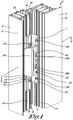
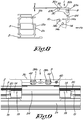
- Figure 1 shows a concealed hinge 1 according to the invention positioned between a frame profile 2 of a fixed frame 3 of a door 4 and a leaf profile 5 of a rotatable leaf 6 of the door 4.
- a door 4 that opens inwards is shown, whereby the leaf 6 is opened from the outside A to the inside B.
- the inside B is also referred to as the hinge side B and the outside A the non-hinge side A.
- the invention is also applicable to a door opening outward, in which case the hinge side and the non-hinge side are then switched.
- the frame profiles 2 and the leaf profiles 5 are profiles with several hollow chambers, whereby the profiles are thermally insulated and composed of a hollow shell 2a and 5a on the non-hinge side A of the door, a hollow shell 2b and 5b on the hinge side B of the door and a hollow intermediate shell 2c and 5c in between and whereby these shells are connected to each other by means of insulating bars 2d and 5d made from a thermally insulating material.
- the hinge 1 is composed of a frame section 8 for attaching on the frame profile 2 and a leaf section 9 for attaching on the leaf profile 5, said sections 8 and 9 being hingeably connected to each other by means of a shaft 10.
- a recess 11 has been milled on the level of one of the insulating bars 2d, said recess 11 forming an access to a hollow chamber 2g of the frame profile 2.
- the hinge 1 is concealed in said hollow chamber 2g of the frame profile 2 and in the space 12 between the walls 2e and 5e of the frame profile 2 and of the leaf profile 5 facing each other.
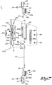
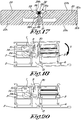
- the frame section 8 of the hinge 1 contains two clamping blocks 14 which can be clamped at a distance from each other on the ends of the recess 11 in the frame profile 2 by means of a clamping plate 15 which supports on the frame profile 2 and in which a passage 16 is provided for a screw 17 which is screwed in a screw hole 18 of the clamping blocks 14 to thus tighten the clamping block 14 toward itself to clamp one or more of said details 13.
- the passage 16 is in the form of a slotted hole that allows the clamping block 14 to be slid in the axial direction of the shaft 10 in relation to the clamping plate 15.
- the clamping plate 15 is provided with two parallel edges 19, in the example respectively in the form of a curved lip 19a with which the clamping plate 15 can be hooked in a fitting groove 13a or other detail on one side of the recess 11 and in the form of a tooth 19b with which the clamping plate 15 can rest on an edge 13b or other detail on the other side of the recess 11.
- the clamping blocks 14 are provided with a protrusion 14a that can grip behind a roll-in tooth 13c or another detail of the frame profile 2 and can be tightened against it by screwing said screw 17, as shown in figure 11 .
- the clamping blocks 14 are provided with a drilled hole 14b for the shaft 10 of the hinge 1, said drilled holes 14b being oriented vertically in each other's extension in a mounted condition and located up to a certain depth D of the wall 2e in the hollow chamber 2g, because the shaft 10 is located at a distance from the side of the clamping blocks 14 facing the clamping plate 15.
- the shaft 10 is fitted with its ends in the drilled holes 14b and clamped therein by means of clamp screws 14c which are screwed in a radially arranged threaded hole 14d in the clamping block 14 or in any other way.
- the frame section 8 of the hinge 1 is provided with a height adjustment with which the height of the leaf 6 in the fixed frame 3 can be adjusted by sliding the clamping blocks 14 radially in relation to the clamping plates 15.
- the clamping plates 15 are provided with a leg 20 at their axial ends facing away from each other, which is inserted through the recess 11 in the frame profile 2 in the hollow chamber 2g of this profile 2 and is located next to a clamping block 14 opposite an external end wall 14f of the clamping block 14 facing away from the shaft 10.
- the leg 20 of the bottom clamping plate 15 rests on the bottom end of said recess 11 as shown in the cross-section of figure 13 , or on another detail 13 of the chamber 2g.
- the clamping blocks 14 can be slid axially in the chamber 2g by means of an adjustment screw 21 which can be screwed in and out in the direction of said leg 20 of the clamping plate 15 in a thread 14e in the clamping block 14 with its tip resting on the leg 20, preferably on a supporting surface of the leg 20 perpendicular to the adjustment screw 21.
- the thread 14e extends through the clamping block 14 from an inner end wall to the outer end wall 14f in a slanting direction in relation to the axial direction and away from the clamping plate toward the leg 20 and with its entry for the adjustment screw 21 located at a radial distance from the shaft 10 and located between the shaft 10 and clamping plate 15.
- this adjustment screw 21 is easily accessible for a screwdriver 22 or the like to adjust the height of the leaf section 9 of the hinge 1 with the leaf 6 attached thereto in the fixed frame 3 for a door 4 with a mounted and turned open leaf 6.
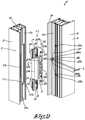
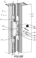
- the leaf section 9 of the hinge 1 contains a hinge leaf 23 which is attached to said wall 5e of the leaf profile 5 and on which a hook-shaped section 24 is provided which is fitted hingeably with its free end around said shaft 10 of the frame section 8 of the hinge 1 between the two clamping blocks 14 of the hinge 1.
- this leaf profile 5 is provided with three anchors 25, 25a, 25b and 25c respectively, for example in the form of clamp anchors, blind rivets, screw bushings, rivets or the like, preferably clamp anchors, which are fitted in the known way through holes 26 that were premounted in the wall 5e in question of the leaf profile 5 and which are positioned on the level of the angular points of a triangle 27 as shown in the dashed line in figure 2 , the base of which extends in the longitudinal direction of the leaf profile 5 and the third angular point at a transverse distance therefrom and oriented toward the stop lip 5f of the leaf profile 5.
- clamp anchors which are fitted in the known way through holes 26 that were premounted in the wall 5e in question of the leaf profile 5 and which are positioned on the level of the angular points of a triangle 27 as shown in the dashed line in figure 2 , the base of which extends in the longitudinal direction of the leaf profile 5 and the third angular point at a transverse distance therefrom and oriented toward the stop lip
- the two anchors 25a and 25b along the base of said triangle 27 are inserted completely or practically completely through the holes 26 in the leaf profile 5 and are provided with an internal thread oriented transversely along said wall 5e of the leaf profile 5.
- the third anchor 25c is an anchor that is separate from the hinge leaf 23 and separately mounted on the leaf profile 5 and with its body is stuck in the leaf profile 5 and has an end in the form of a semi-cylindrical plug 28 which with a certain length E protrudes from the wall 5e of the leaf profile 5 in a direction perpendicular to this wall 5e and which at its end is provided with a widened head 28a.
- the plug 28 On the side turned away from the stop lip 5f, the plug 28 is provided with a flattening 28b.
- the hinge leaf 23 has two longitudinal opposite side edges, respectively a first and a second edge 23b and 23a, which in mounted condition extend in the longitudinal direction of the leaf profile 5, whereby the first side edge 23b in closed condition of the window is oriented toward the stop lip 5f of the leaf 5 on the hinge side B and the second side edge 23a is oriented toward the stop lip 2f of the frame 2 on the non-hinge side A.
- two passages 23c are provided for screws 29 which can be screwed in said screw anchors 25a and 25b for attaching the hinge leaf 23, whereby the hinge leaf 23 is tightened with its supporting surface 30 against the leaf profile 5.
- This supporting surface 30 is provided with a sunken recess 31 with an access 31a along said second edge 23b of the hinge leaf 23.
- This sunken recess 31 contains a clip mechanism 32 in which the plug 28 of the third anchor 25 can be clipped by hooking the plug 28 with its longitudinal axis perpendicular or approximately perpendicular to the supporting surface 30 in a radial direction along said access 31a of the sunken recess 31 in the clip mechanism 32 in a direction that is essentially parallel with the plane of the supporting surface 30 and essentially transversely to the second edge 23b or therefore in a plane which extends essentially transversely on the axial direction of the shaft 10, said clip mechanism 32 being such that the clipped in plug 28 cannot unintentionally be pulled out in the opposite direction.
- this clip mechanism 32 which only works in one direction, is formed by two folded leaf springs 33, each with a clamped leg 33a on either side of the sunken recess 31 and a connecting leg 33b perpendicular to this which extends in the sunken recess 31, whereby these last legs 33b are folded such that together they form a double bell-shaped channel 34 as it were that extends in a direction transverse to the second edge 23b of the hinge leaf 23 and which is provided with a first narrowed entry 34a on the end along the side of the second edge 23b and with a second narrowed entry 34b on the other end and with a wider central section 34c in an intermediate location that can form a seat for said protruding plug 28, at least for the section of the plug 28 up to the widened flattened head 28a.
- the leaf springs 33 are clamped in the hinge leaf 23 with the free end 33c of the leg 33a, more specifically in this case between support points 35a and 35b, whereby the legs 33a in resting position extend in a practically parallel way with the second edge 23b.
- the legs 33a are against a stop 36 or at small distance therefrom, such that the legs 33a can be pushed in the direction of arrow P away from the edge 23b, whereby the support point 35b serves as inflection point as illustrated in figure 16 , but said stop 36 ensuring that the legs 33a cannot spring back in the opposite direction of arrow P beyond their original resting position or can only be pushed a small distance past this resting position.
- a passage 37 is provided in the hinge leaf 23 which extends in the extension of the bell-shaped channel 34 into the sunken recess 31.
- the legs 33b of the bell-shaped channel 34 can be pushed apart by means of a tool 38 with a sufficiently wide head 38a to push apart the legs 33b along the second entry 34b of the channel 34 as shown in figure 21 , whereby in that case the leaf springs 33 can bend again around the support point 35b, away from the stop 36, such that the first entry 34a of the channel 34 also opens and the plug 28 can be pushed simultaneously using the same tool 38 out of the clip mechanism 32 by pushing this tool 38 on the flattening 28b of the plug 28 as shown in figure 21 .
- the tool 38 is formed by a threaded rod 38b which is screwed in said passage 37 and with its head 38a sticks in the recess 31 and which can be screwed in and out with a screwdriver 22 or the like, as shown in figure 22 .
- the widened head 28a of the plug 28 also means that the plug 28 cannot unintentionally be pulled out of the clip mechanism 32 in its axial direction.
- the supporting surface 30 of the hinge leaf 23 is provided with a chamfer 30a over an angle H of for example 3 to 4° as indicated in figure 8 , or a rounding, such that when tightening the screws 29 along the first edge 23a of the hinge leaf 23, the hinge leaf 23 in the direction of arrow Q, as indicated in figure 18 , tilts around the bend line 30b in the transition between the flat section of the supporting surface 30 and the chamfer 30a, causing the hinge leaf 23 to be tightened by the lever action against the widened head 28a of the plug 28, such that the hinge leaf 23 is firmly anchored in three points at the level of the anchors 25 on the leaf profile 5. All play necessary to easily hook in over the plug 28 is removed when screwing it in.
- the lever action can also be applied as a separate aspect of the invention, in other words, independent from the clip mechanism 32 with plug 28, as described above.
- the plug 28 can also be realised in the form of a bolt or screw with widened head 28a, which is pre-screwed into the leaf 6 with a section protruding from the wall 5e, whereas the recess 31 in the hinge leaf 23 on the edge 23b can be replaced for example by a keyhole opening with which the hinge leaf 23 can be hooked over the plug 28 under the widened head 28a without use of a clip mechanism and can then be tightened against the widened head 28a by tightening the screws 29 on the opposite edge 23a of the hinge leaf 23 by the lever action of the chamfer or rounding 30a.
- this lever action is also applicable for attaching a hinge to the frame with a hinge leaf on the frame side.
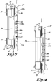
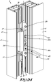
- the hook-shaped section 24 of the leaf section 9 of the hinge 1 is moveably attached to the hinge leaf 23 along the first edge 23a of the hinge leaf 23.
- the moveable hook-shaped section 24 is provided with a slat-shaped foot 24a and the hinge leaf 23 is provided with an upstanding rib 23d with a groove 23e therein which extends in the longitudinal direction of the hinge leaf 23 and in which the foot 24a of the hook-shaped section 24 is fitted with the hook-shaped section oriented toward the second edge 23b of the hinge leaf 23.
- the hinge 1 is provided with an adjustment of the lateral orthogonal distance from the hook-shaped section 24 to the hinge leaf 23.
- the adjustment bar 39 is slideable in the longitudinal direction, for example because in the adjustment bar 39, longitudinal slotted holes 39a have been provided and screws 39b which are screwed through these slotted holes 39a in the upstanding rib 23d of the hinge leaf 23.
- the longitudinal position of the adjustment bar 39 is for example adjustable by means of an adjusting screw 40 with an excentric cam 40a or another adjusting means which by rotating the adjustment bar 39 in one or the other direction can slide and which is accessible through an opening in the upstanding rib 23d.
- an adjusting screw 40 with an excentric cam 40a or another adjusting means which by rotating the adjustment bar 39 in one or the other direction can slide and which is accessible through an opening in the upstanding rib 23d.
- one or more slotted holes 41 are provided which are slanting in relation to the supporting surface 30 of the hinge leaf 23 and the adjustment bar 39 is provided with one or more pins 42 which are slideably guided in the slotted holes 41, all this such that a rotation of the adjusting screw 40, for example in a direction of rotation according to arrow S in figure 23 , causes the adjustment bar 39 to slide in the direction of arrow T and the hook-shaped section 24 to move away from the hinge leaf 23 according to arrow U or toward the hinge leaf when turning the adjusting screw 40 in the other direction of rotation.
- the adjusting screw 40 is adjustable using a tool as in figure 24 .
- This adjustment allows the closed position of the leaf 6 in relation to the fixed frame 3 to be adjusted.
- Said adjustment can, as the case may be, also be realised in other ways.
- holes 26 are drilled in the corresponding places for the anchors 25 which are also already premounted.
- the recesses 11 and holes 26 with anchors 25 can also already be provided beforehand in the factory.
- the assembled hinges 1 can then be attached to the frame 2, after having removed the clamping plates 15 first.
- clamping blocks 14 are hereby tilted by the hinges 1 in the recesses 11 and these clamping blocks 14 are anchored by means of the clamping plates 15 which are fitted on the frame 2 and the hinges 1 are solidly fixed by tightening the clamping blocks 14 to the clamping plates 15 using the screws 17 as shown in figures 8 to 12 .
- hinges 1 are then turned to their closed position as shown in figure 14 , whereby the supporting surface 30 of the hinge leaves 23 is approximately parallel with the wall 2e of the frame profile 2 on which the hinges 1 are mounted, and therefore perpendicular to the plane of the door opening, such that the access 31a of the sunken part 31 with the clip mechanism 32 therein becomes accessible along the hinge side B of the door 4.
- the leaf 6 is then held approximately parallel to the plane of the door opening and moved in a direction perpendicular thereto in the fixed frame 3 and clipped by clicking the leaf 6 with its plugs 28 in the clip mechanisms 32.
- the leaf 6 can then be released as the plugs 28 are clipped and can no longer unintentionally come loose.
- the leaf 6 can then be opened to screw the hinges 1 on the leaf 6 by tightening the screws 29 in the screw anchors 25a and 25b, such that the hinge leaf 23 is also clamped against the head 28a of the plug 28 by said lever action thanks to the chamfer 30a of the supporting surface 30 of the hinge leaf 23, such that on the leaf a solid three-point connection is realised with the three anchors 25.
- the position of the leaf 6 in the fixed frame 3 can be adjusted, whereby for this adjustment the leaf 6 is opened to adjust the position of the leaf section 9 of the hinges 1 in relation to the frame section 8.
- a first adjustment consists in adjusting the height of the leaf 6 in the fixed frame 3 by, as shown in figure 13 , loosening or tightening the adjustment screw 21 of the frame section 8 of the bottom clamping block 14, which can easily be done with a screwdriver 22 or the like because this adjustment screw 21 is in an easily accessible place with the leaf in a mounted condition as shown in figure 1 .
- a second adjustment relates to the lateral position of the leaf 6 in the fixed frame 3 which can be adjusted by slightly loosening the screws 39b on the leaf section 9 of the hinges 1 such that the position of the hook-shaped section 24 in relation to the hinge leaf 23 can be adjusted and by then turning the adjusting screw 40 with the excentric cam 40a such that the foot 24a of the hook-shaped section 24 is moved deeper in or out of the groove 23e as shown in the figures 23 and 24 .
- the screws 39b can be fixed to fix the leaf 6 on the hinges 1.
- the frame section 8 of the hinge 1 as described above can also be combined with another leaf section 9, for example of a traditional hinge or vice versa, such that a leaf section 9 of a hinge 1, as described above, can be combined with another frame section 8, for example of a traditional hinge.
- the anchors 25a, 25b do not necessarily need to be executed as clamp anchors, but can for example also be replaced with rivet nuts, screw sockets, tensioning plates or any other means for attaching a screw.
- the clamp anchor 25c for attaching the plug 28 can for example also be replaced by a screw, rivet or the like.
Landscapes
- Engineering & Computer Science (AREA)
- Mechanical Engineering (AREA)
- Hinges (AREA)
Applications Claiming Priority (1)
| Application Number | Priority Date | Filing Date | Title |
|---|---|---|---|
| BE20185600A BE1026576B1 (nl) | 2018-08-28 | 2018-08-28 | Verdektliggend scharnier voor een deur of raam en deur of raam daarmee uitgerust en werkwijze voor het monteren van een vleugel in een vast kader van een raam of deur. |
Publications (2)
| Publication Number | Publication Date |
|---|---|
| EP3611320A2 true EP3611320A2 (de) | 2020-02-19 |
| EP3611320A3 EP3611320A3 (de) | 2020-04-29 |
Family
ID=63713563
Family Applications (1)
| Application Number | Title | Priority Date | Filing Date |
|---|---|---|---|
| EP19191244.3A Pending EP3611320A3 (de) | 2018-08-28 | 2019-08-12 | Verdecktes scharnier für eine tür oder ein fenster sowie tür oder fenster mit solch einem mechanismus und verfahren zur montage eines flügels in einem festen rahmen eines fensters oder einer tür |
Country Status (3)
| Country | Link |
|---|---|
| EP (1) | EP3611320A3 (de) |
| CN (1) | CN110863726B (de) |
| BE (1) | BE1026576B1 (de) |
Cited By (1)
| Publication number | Priority date | Publication date | Assignee | Title |
|---|---|---|---|---|
| WO2025040582A1 (de) * | 2023-08-18 | 2025-02-27 | Dr. Hahn Gmbh & Co. Kg | Bandteil und bandanordnung |
Families Citing this family (1)
| Publication number | Priority date | Publication date | Assignee | Title |
|---|---|---|---|---|
| TWI908423B (zh) * | 2024-10-25 | 2025-12-11 | 蔡雨霖 | 櫥櫃鉸鏈 |
Citations (3)
| Publication number | Priority date | Publication date | Assignee | Title |
|---|---|---|---|---|
| WO1998022680A1 (en) | 1996-11-21 | 1998-05-28 | Grorud Industrier A/S | Device for a door hinge structure |
| WO2003029589A1 (en) | 2001-08-29 | 2003-04-10 | Frip Ab | Hinge device |
| DE202010004163U1 (de) | 2010-03-24 | 2010-07-08 | Konrad, Andrea | Verdeckt liegendes Edelstahl-Türband insbesondere für Aluminium- und Kunststoff-Türen |
Family Cites Families (3)
| Publication number | Priority date | Publication date | Assignee | Title |
|---|---|---|---|---|
| DE3340634A1 (de) * | 1983-11-10 | 1985-05-30 | Ford-Werke AG, 5000 Köln | Verfahren und vorrichtung zum vorab- und/oder endgueltigen anschlagen einer fahrzeugtuer |
| WO2011060835A1 (de) * | 2009-11-23 | 2011-05-26 | Dr. Hahn Gmbh & Co. Kg | Bandanordnung für türen, fenster oder dergleichen |
| CN107542344A (zh) * | 2016-06-29 | 2018-01-05 | 江阴市桐岐五金电器厂 | 一种门铰链固接机构 |
-
2018
- 2018-08-28 BE BE20185600A patent/BE1026576B1/nl active IP Right Grant
-
2019
- 2019-08-12 EP EP19191244.3A patent/EP3611320A3/de active Pending
- 2019-08-28 CN CN201910800184.2A patent/CN110863726B/zh active Active
Patent Citations (3)
| Publication number | Priority date | Publication date | Assignee | Title |
|---|---|---|---|---|
| WO1998022680A1 (en) | 1996-11-21 | 1998-05-28 | Grorud Industrier A/S | Device for a door hinge structure |
| WO2003029589A1 (en) | 2001-08-29 | 2003-04-10 | Frip Ab | Hinge device |
| DE202010004163U1 (de) | 2010-03-24 | 2010-07-08 | Konrad, Andrea | Verdeckt liegendes Edelstahl-Türband insbesondere für Aluminium- und Kunststoff-Türen |
Cited By (1)
| Publication number | Priority date | Publication date | Assignee | Title |
|---|---|---|---|---|
| WO2025040582A1 (de) * | 2023-08-18 | 2025-02-27 | Dr. Hahn Gmbh & Co. Kg | Bandteil und bandanordnung |
Also Published As
| Publication number | Publication date |
|---|---|
| CN110863726A (zh) | 2020-03-06 |
| CN110863726B (zh) | 2022-11-22 |
| EP3611320A3 (de) | 2020-04-29 |
| BE1026576B1 (nl) | 2020-03-30 |
| BE1026576A1 (nl) | 2020-03-24 |
Similar Documents
| Publication | Publication Date | Title |
|---|---|---|
| EP1907712B1 (de) | Verfahren zum befestigen eines zubehörteils an einer mauer und befestigungssatz hierfür | |
| US20110283624A1 (en) | Adjustable door mounting system | |
| US9644411B2 (en) | Adjustable hinge | |
| EP3611320A2 (de) | Verdecktes scharnier für eine tür oder ein fenster sowie tür oder fenster mit solch einem mechanismus und verfahren zur montage eines flügels in einem festen rahmen eines fensters oder einer tür | |
| CA2812566A1 (en) | Shower door assembly | |
| US7650670B2 (en) | Hinge attachment system and method | |
| CA2484925A1 (en) | Assembly comprising a door leaf and hinges, and a shower stall | |
| US5787639A (en) | Door and frame mounting enabling door hanger bolt assembly | |
| EP2093362A1 (de) | Verfahren und Klemmsystem zur Befestigung eines Scharniers oder anderen Beschlags an Profilen für Fenster und Türen | |
| EP3677745A1 (de) | Türprofil und entsprechendes selbstklemmendes scharnier und selbstklemmender adapter | |
| US11828102B2 (en) | Adjustable packer apparatus | |
| CN110821924B (zh) | 用于将铁制品紧固到窗或门的中空型材上的夹紧锚固件 | |
| US20060210355A1 (en) | Device comprising two hollow profiles that are held together by means of a connecting screw, and corresponding tool | |
| US20070163083A1 (en) | Hinge housing for door leaves which are made at least in some areas from thin-walled metal or metal hollow sections | |
| GB2639250A (en) | Wall fixing | |
| WO2011093759A1 (en) | A mounting tool for mounting/demounting of windows, doors and similar in a wall opening | |
| EP4618809A1 (de) | Verstellbare stützvorrichtung zum aufhängen von möbeln an einer wand | |
| EP2248975B1 (de) | Klemmanker zur Befestigung von Beschlägen an einem Hohlprofil eines Fensters oder einer Tür | |
| EP2280142A2 (de) | Scharnier zur Montage von Glasscheiben oder ähnlichen Strukturen | |
| GB2311095A (en) | Hinge | |
| EP1736618A2 (de) | Ein einstellbarer Handgriff und ein Montageverfahren eines solchen Handgriffes | |
| BE1026575A1 (nl) | Verdektliggend scharnier voor een deur of raam en deur of raam daarmee uitgerust en werkwijze voor het monteren van een vleugel in een vast kader van een raam of deur | |
| DK1881149T3 (en) | Holder for attaching a shade system and shading system with such holder | |
| US12486700B2 (en) | Gate block method and hardware | |
| EP1722057A2 (de) | Verstellbare Unterstützungsvorrichtung für Tür- und Fensterscharniere |
Legal Events
| Date | Code | Title | Description |
|---|---|---|---|
| PUAI | Public reference made under article 153(3) epc to a published international application that has entered the european phase |
Free format text: ORIGINAL CODE: 0009012 |
|
| STAA | Information on the status of an ep patent application or granted ep patent |
Free format text: STATUS: THE APPLICATION HAS BEEN PUBLISHED |
|
| AK | Designated contracting states |
Kind code of ref document: A2 Designated state(s): AL AT BE BG CH CY CZ DE DK EE ES FI FR GB GR HR HU IE IS IT LI LT LU LV MC MK MT NL NO PL PT RO RS SE SI SK SM TR |
|
| AX | Request for extension of the european patent |
Extension state: BA ME |
|
| PUAL | Search report despatched |
Free format text: ORIGINAL CODE: 0009013 |
|
| AK | Designated contracting states |
Kind code of ref document: A3 Designated state(s): AL AT BE BG CH CY CZ DE DK EE ES FI FR GB GR HR HU IE IS IT LI LT LU LV MC MK MT NL NO PL PT RO RS SE SI SK SM TR |
|
| AX | Request for extension of the european patent |
Extension state: BA ME |
|
| RIC1 | Information provided on ipc code assigned before grant |
Ipc: E05D 7/12 20060101ALI20200324BHEP Ipc: E05D 3/02 20060101ALN20200324BHEP Ipc: E05D 5/02 20060101AFI20200324BHEP |
|
| STAA | Information on the status of an ep patent application or granted ep patent |
Free format text: STATUS: REQUEST FOR EXAMINATION WAS MADE |
|
| 17P | Request for examination filed |
Effective date: 20201028 |
|
| RBV | Designated contracting states (corrected) |
Designated state(s): AL AT BE BG CH CY CZ DE DK EE ES FI FR GB GR HR HU IE IS IT LI LT LU LV MC MK MT NL NO PL PT RO RS SE SI SK SM TR |
|
| RAP1 | Party data changed (applicant data changed or rights of an application transferred) |
Owner name: SOBINCO, NAAMLOZE VENNOOTSCHAP |
|
| RIN1 | Information on inventor provided before grant (corrected) |
Inventor name: VAN PARYS, EMMANUEL |
|
| RIN1 | Information on inventor provided before grant (corrected) |
Inventor name: VAN PARYS, EMMANUEL DIEDERICH CAMILLE |
|
| STAA | Information on the status of an ep patent application or granted ep patent |
Free format text: STATUS: EXAMINATION IS IN PROGRESS |
|
| 17Q | First examination report despatched |
Effective date: 20230728 |
|
| 17Q | First examination report despatched |
Effective date: 20230817 |
|
| RIC1 | Information provided on ipc code assigned before grant |
Ipc: E05D 5/02 20060101AFI20260213BHEP Ipc: E05D 7/12 20060101ALI20260213BHEP Ipc: E05D 3/02 20060101ALN20260213BHEP |
|
| GRAP | Despatch of communication of intention to grant a patent |
Free format text: ORIGINAL CODE: EPIDOSNIGR1 |
|
| STAA | Information on the status of an ep patent application or granted ep patent |
Free format text: STATUS: GRANT OF PATENT IS INTENDED |