EP3611065A1 - Parksperrenlöseventil einfache anordnung aus 4-wege-3-positionen (4/3-ventil)-spule (stange) und hülsenventil mit öffnungsfunktion - Google Patents
Parksperrenlöseventil einfache anordnung aus 4-wege-3-positionen (4/3-ventil)-spule (stange) und hülsenventil mit öffnungsfunktion Download PDFInfo
- Publication number
- EP3611065A1 EP3611065A1 EP19182759.1A EP19182759A EP3611065A1 EP 3611065 A1 EP3611065 A1 EP 3611065A1 EP 19182759 A EP19182759 A EP 19182759A EP 3611065 A1 EP3611065 A1 EP 3611065A1
- Authority
- EP
- European Patent Office
- Prior art keywords
- valve
- chamber
- trailer
- port
- park release
- Prior art date
- Legal status (The legal status is an assumption and is not a legal conclusion. Google has not performed a legal analysis and makes no representation as to the accuracy of the status listed.)
- Granted
Links
- 238000007789 sealing Methods 0.000 claims description 33
- 238000004891 communication Methods 0.000 claims description 23
- 230000008878 coupling Effects 0.000 claims description 17
- 238000010168 coupling process Methods 0.000 claims description 17
- 238000005859 coupling reaction Methods 0.000 claims description 17
- 239000000463 material Substances 0.000 claims description 4
- 239000012530 fluid Substances 0.000 description 12
- 238000010276 construction Methods 0.000 description 5
- 230000001419 dependent effect Effects 0.000 description 5
- 239000000725 suspension Substances 0.000 description 5
- 230000007246 mechanism Effects 0.000 description 4
- 238000011161 development Methods 0.000 description 3
- 230000018109 developmental process Effects 0.000 description 3
- 238000004519 manufacturing process Methods 0.000 description 3
- 239000007769 metal material Substances 0.000 description 3
- 241001677259 Acanthophoenix rubra Species 0.000 description 2
- 241000899749 Dypsis lutescens Species 0.000 description 2
- 238000013022 venting Methods 0.000 description 2
- FGRBYDKOBBBPOI-UHFFFAOYSA-N 10,10-dioxo-2-[4-(N-phenylanilino)phenyl]thioxanthen-9-one Chemical compound O=C1c2ccccc2S(=O)(=O)c2ccc(cc12)-c1ccc(cc1)N(c1ccccc1)c1ccccc1 FGRBYDKOBBBPOI-UHFFFAOYSA-N 0.000 description 1
- 230000009471 action Effects 0.000 description 1
- 230000009286 beneficial effect Effects 0.000 description 1
- 230000008901 benefit Effects 0.000 description 1
- 238000013461 design Methods 0.000 description 1
- 238000001746 injection moulding Methods 0.000 description 1
- 239000012528 membrane Substances 0.000 description 1
- 238000012986 modification Methods 0.000 description 1
- 230000004048 modification Effects 0.000 description 1
- 230000000007 visual effect Effects 0.000 description 1
Images


Classifications
-
- B—PERFORMING OPERATIONS; TRANSPORTING
- B60—VEHICLES IN GENERAL
- B60T—VEHICLE BRAKE CONTROL SYSTEMS OR PARTS THEREOF; BRAKE CONTROL SYSTEMS OR PARTS THEREOF, IN GENERAL; ARRANGEMENT OF BRAKING ELEMENTS ON VEHICLES IN GENERAL; PORTABLE DEVICES FOR PREVENTING UNWANTED MOVEMENT OF VEHICLES; VEHICLE MODIFICATIONS TO FACILITATE COOLING OF BRAKES
- B60T15/00—Construction arrangement, or operation of valves incorporated in power brake systems and not covered by groups B60T11/00 or B60T13/00
- B60T15/02—Application and release valves
- B60T15/04—Driver's valves
- B60T15/041—Driver's valves controlling auxiliary pressure brakes, e.g. parking or emergency brakes
-
- B—PERFORMING OPERATIONS; TRANSPORTING
- B60—VEHICLES IN GENERAL
- B60T—VEHICLE BRAKE CONTROL SYSTEMS OR PARTS THEREOF; BRAKE CONTROL SYSTEMS OR PARTS THEREOF, IN GENERAL; ARRANGEMENT OF BRAKING ELEMENTS ON VEHICLES IN GENERAL; PORTABLE DEVICES FOR PREVENTING UNWANTED MOVEMENT OF VEHICLES; VEHICLE MODIFICATIONS TO FACILITATE COOLING OF BRAKES
- B60T15/00—Construction arrangement, or operation of valves incorporated in power brake systems and not covered by groups B60T11/00 or B60T13/00
- B60T15/02—Application and release valves
- B60T15/04—Driver's valves
-
- B—PERFORMING OPERATIONS; TRANSPORTING
- B60—VEHICLES IN GENERAL
- B60T—VEHICLE BRAKE CONTROL SYSTEMS OR PARTS THEREOF; BRAKE CONTROL SYSTEMS OR PARTS THEREOF, IN GENERAL; ARRANGEMENT OF BRAKING ELEMENTS ON VEHICLES IN GENERAL; PORTABLE DEVICES FOR PREVENTING UNWANTED MOVEMENT OF VEHICLES; VEHICLE MODIFICATIONS TO FACILITATE COOLING OF BRAKES
- B60T13/00—Transmitting braking action from initiating means to ultimate brake actuator with power assistance or drive; Brake systems incorporating such transmitting means, e.g. air-pressure brake systems
- B60T13/10—Transmitting braking action from initiating means to ultimate brake actuator with power assistance or drive; Brake systems incorporating such transmitting means, e.g. air-pressure brake systems with fluid assistance, drive, or release
- B60T13/24—Transmitting braking action from initiating means to ultimate brake actuator with power assistance or drive; Brake systems incorporating such transmitting means, e.g. air-pressure brake systems with fluid assistance, drive, or release the fluid being gaseous
- B60T13/26—Compressed-air systems
- B60T13/268—Compressed-air systems using accumulators or reservoirs
-
- B—PERFORMING OPERATIONS; TRANSPORTING
- B60—VEHICLES IN GENERAL
- B60T—VEHICLE BRAKE CONTROL SYSTEMS OR PARTS THEREOF; BRAKE CONTROL SYSTEMS OR PARTS THEREOF, IN GENERAL; ARRANGEMENT OF BRAKING ELEMENTS ON VEHICLES IN GENERAL; PORTABLE DEVICES FOR PREVENTING UNWANTED MOVEMENT OF VEHICLES; VEHICLE MODIFICATIONS TO FACILITATE COOLING OF BRAKES
- B60T13/00—Transmitting braking action from initiating means to ultimate brake actuator with power assistance or drive; Brake systems incorporating such transmitting means, e.g. air-pressure brake systems
- B60T13/10—Transmitting braking action from initiating means to ultimate brake actuator with power assistance or drive; Brake systems incorporating such transmitting means, e.g. air-pressure brake systems with fluid assistance, drive, or release
- B60T13/24—Transmitting braking action from initiating means to ultimate brake actuator with power assistance or drive; Brake systems incorporating such transmitting means, e.g. air-pressure brake systems with fluid assistance, drive, or release the fluid being gaseous
- B60T13/26—Compressed-air systems
- B60T13/40—Compressed-air systems indirect, i.e. compressed air booster units indirect systems
- B60T13/403—Compressed-air systems indirect, i.e. compressed air booster units indirect systems specially adapted for coupling with dependent systems, e.g. tractor-trailer systems
Definitions
- the invention relates to a park release valve for a trailer vehicle having a truck and a trailer and having a pneumatic brake system, and for controlling an emergency braking modulator (EBM) and/or spring-loaded brakes (SBA) of the trailer, comprising: a valve housing, a moveable valve element, and a push button attached to the valve element for moving the valve element relative to the valve housing, the valve housing comprising: a supply port for receiving a supply pressure from the truck; a reservoir port for connection with a trailer reservoir; a delivery port for providing a brake pressure for at least an emergency braking modulator (EBM) and/or one spring-loaded brake (SBA) of the trailer; and an exhaust port for releasing pressure to the atmosphere; and the valve element is moveable into at least three positions, wherein in a parking position the delivery port is in communication with the exhaust port; in a driving position the delivery port is in communication with the supply port; and in a release position the delivery port is in communication with the reservoir port; and wherein, when the supply pressure exceeds
- a park release valve of the aforementioned type is for example disclosed in EP 3 228 512 A1 .
- the park release valve disclosed therein comprises an outer control piston and an inner control piston provided therein, a supply port, a supply container port, a release port and a working port, wherein the outer control piston is moveable in at least three positions.
- a release position the supply container port is connected with the working port.
- a driving position the supply port is connected with the supply container port and the working port.
- the working port is connected to the release port.
- the inner control piston is supplied with the supply pressure and pushes against the outer control piston in such a way that the outer control piston is restricted in its movement, such that it cannot move into the release position.
- driving switching in the release position is prohibited.
- the pneumatic brake system of a trailer typically is connected to the truck by means of two pneumatic lines.
- One of the pneumatic lines supplies a control pressure via a control connection to the trailer (yellow palm coupling). This connection also is referred to "brake” or “control”.
- the other line provides supply pressure via a coupling called “supply” to the trailer (also called “red palm coupling”).
- Such braking systems have integrated safety functions for the event of a brake-off of the supply line. For carrying out these safety functions, the pressure in the supply line is observed. When a high pressure loss is identified, the trailer is automatically braked using spring-loaded brakes (SBA) of the trailer.
- SBA spring-loaded brakes
- the truck usually comprises a reservoir for pressurized air which is filled via the supply connection. Due to this arrangement, the trailer may use its service brakes a couple of times without requiring additional pressurized air from the truck.
- Prior art pneumatic braking systems comprise combined brakes having a membrane type service brake piston and a spring-loaded brake piston in one component. This bears the advantage that brake piston, brake lever and brake discs only need to be in one component and not in two components.
- Such combined braking cylinders are called Tristop cylinders. However, a separated arrangement also is contemplated.
- the spring-loaded brakes In a trailer, which is paked and disconnected from the truck, the spring-loaded brakes (SBA) are activated, i.e. the spring-loaded brake cylinders are vented. For maneuvering or shunting the trailer, the spring-loaded brakes need to be released.
- a special park release valve is provided, which supplies the spring-loaded brakes directly or indirectly with pressurized air of the reservoir of the trailer. After finishing the maneuvering, the spring-loaded brakes need to be vented again. Therefore, the park release valve is brought into a park position.
- the park release valve may be formed out of two separately operable venting units.
- a more compact valve is formed by combining the two functions integrating them as far as possible.
- a parking brake valve for a control device for a trailer of a vehicle comprising a service brake having a service brake cylinder, a parking brake having a spring brake cylinder, an air suspension having air suspension bellows and a housing.
- a sliding valve element is guided for a sliding movement and sealed, the sliding valve element comprising a manual button or handle located outside from the housing.
- the sliding valve element is optionally manually movable into an aerating position or a de-aerating position for the spring brake cylinder of the parking brake.
- the parking brake valve moreover comprises an opening valve located in a line leading to the spring brake cylinders, wherein the opening valve is switchable by a pressure in the line of the air suspension leading to the air suspension bellows from the closed position into an open position.
- the parking brake valve in this disclosure is integrated with the air suspension system of the trailer. Further integrated devices are known from DE 198 18 982 C2 and DE 198 54 881 B4 .
- the object of the present invention is to provide a park release valve of the type known from EP 3 228 512 A1 which is easy to manufacture, highly integrated and compact.
- this object is solved by a park release valve of the type defined in the introductory portion, wherein the valve element is formed as a valve spool having at least one land and at least one valley, wherein the valve housing defines at least a first chamber, a second chamber, a third chamber, a fourth chamber and a fifth chamber between the valve spool and the housing which selectively closable by moving the valve spool.
- the valve element is formed as a valve spool having at least one land and at least one valley
- the valve housing defines at least a first chamber, a second chamber, a third chamber, a fourth chamber and a fifth chamber between the valve spool and the housing which selectively closable by moving the valve spool.
- at least two, three, four, or five of the chambers are independent from each other.
- valve spool acts together with the housing for selectively closing at least one of the chambers and connecting other chambers such that fluid may flow from one chamber to another chamber for connecting respectively the ports in the parking position, driving position and release position.
- the ports i.e. the supply port, reservoir port, delivery port and exhaust port are connected with at least one of the chambers.
- a 4-way 3-position valve is obtained, with a valve spool and sleeve construction, wherein the sleeve is formed by the valve housing.
- the park release valve comprises a sixth chamber in the valve housing in which a piston is moveable and seated, the sixth chamber is in communication with the supply port.
- the piston is seated in a movable way in the sixth chamber such that when pressure is supplied to the supply port, the piston is moved from a first retracted position to a second extended position.
- the function is similar to the function of the control piston disclosed in EP 3 228 512 A1 .
- the valve spool comprises a first end and a second end, wherein the push button is attached to the first end and the second end is adapted to selectively engage the piston.
- the piston preferably comprises an inner hollow portion in which the second end of the valve spool is moveable and seated.
- the piston thus comprises a bottom wall and an axially extending side wall.
- the piston selectively contacts the second end of the valve spool for pushing the valve element from the release position to the driving position or preventing the valve element from being moved from one of the driving position and the parking position into the release position.
- the piston preferably is in the second extended position.
- the valve spool comprises a first land, a second land, and a third land, wherein a first valley separates the first and second lands, and a second valley separates the second and third lands.
- a first valley separates the first and second lands
- a second valley separates the second and third lands.
- the second valley connects the fourth and fifth chambers
- the first valley connects the second and third chambers
- the second valley connects the third and fourth chambers
- the first valley connects the first and second chambers.
- the supply port is in communication with the reservoir port for filling the trailer reservoir.
- the trailer usually does not have a separate air production system and therefore is required to be supplied by the truck for filling the reservoir of the trailer.
- This is preferably at least done in the driving position, since in this position the truck is driving, and the air production system of the truck is running.
- the supply port is in communication with the reservoir for filling the trailer reservoir.
- the reservoir can be filled.
- the truck does not provide pressurized air to the supply port and therefore the reservoir of the trailer cannot be filled anyway.
- a check valve is provided between the supply port and the reservoir port for prohibiting flow from the reservoir port to the supply port.
- This in particular is beneficial when the supply port in every position of the valve spool is in communication with the reservoir port for filling the trailer reservoir.
- the check valve closes the communication between the supply port and the reservoir and prohibits flow from the reservoir to the supply port.
- the valve housing comprises a valve housing body and at least one chamber insert which is seated in a central recess formed in the housing body, the chamber insert comprising a central passage for receiving the valve spool therein and moreover comprises at least a first through-hole for forming the first chamber.
- the chamber insert comprises further a second through-hole for forming the second chamber, a third through-hole for forming the third chamber, a fourth through-hole for forming the fourth chamber, and a fifth through-hole for forming the fifth chamber.
- the chamber insert together with the housing body forms the different chambers in the valve housing.
- the chamber insert comprises at least a first sealing ring, which seals radially outwardly against an inner surface of the central recess and radially inwardly against the valve spool.
- the chamber insert comprises a second sealing ring, a third sealing ring, and a fourth sealing ring, which each seal radially outwardly against the inner surface of the central recess and radially inwardly against the valve spool.
- Those sealing rings help to define the chambers and support a grid sealing between the chambers to prevent air passing from one chamber to another chamber without purpose.
- the park release valve may comprise a first lip seal for sealing the first end of the valve spool, and a second lip seal for sealing the second end of the valve spool.
- the lip seals are preferably used to seal between the chamber insert and the valve spool, or they are used to seal the valve housing body and the valve spool, dependent on the construction of the chamber insert.
- the chamber insert is formed from a plastic material and releasably seated within the valve housing body.
- the chamber insert preferably is held in place by a fixing screw, or multiple fixing screws.
- the chamber insert is engaged with the valve housing body in a form-locking fit, e.g. by a snap fit.
- the chamber insert can also be formed from a metal material.
- the sealing rings and lip seals can be formed integrally with the chamber insert, e.g. by means of two-component injection molding.
- the park release valve comprises a position indicator at the push button, which in the parking position is retracted into the push button, in the driving position is substantially flush with the push button, and in the release position protrudes from the push button.
- the indicator has a different color than the push button. This further increases a visual understanding of the position of the park release valve. E.g. the indicator may be red, while the push button itself is black.
- a pneumatic brake system for a trailer of a trailer vehicle having a truck and a trailer comprising: a trailer reservoir, a truck supply coupling for receiving a supply pressure from the truck, at least one spring-loaded brake (SBA), and a park release valve according to any of the beforehand described preferred embodiments of the park release valve according to the first aspect of the invention.
- SBA spring-loaded brake
- Fig. 1 shows an overall view of a vehicle 100 having a truck 102 and a trailer 104 and having a pneumatic brake system 106 for the trailer 104.
- the pneumatic brake system 106 of the trailer 104 comprises four spring-loaded brakes 108a, 108b, 108c, 108d for braking the trailer 104 in a parking position, as well as optionally braking the trailer 104 in emergency situations.
- the trailer 104 comprises service brakes 109a, 109b for braking the trailer during normal operation.
- Both, the spring-loaded brakes 108a- 108d as well as the service brakes 109a, 109b are supplied with supply pressure PR from a reservoir 4, which in turn is supplied by the truck 102 via a supply coupling 110 (red palm coupling).
- the trailer 104 receives a truck supply pressure P1 via the supply coupling 110.
- the trailer 104 comprises a control coupling 112 (yellow palm coupling) for receiving a control pressure PC from the truck 102 which indicates a braking signal for the trailer 104.
- the supply coupling 110 is connected via a first pressure line 113 to a park release valve 10 which will be described below in more detail.
- the park release valve 10 in turn is connected to a second pressure line 114 which in turn is connected to the reservoir 4.
- reservoir 4 is supplied with the supply pressure for the reservoir P1 from the park release valve 10.
- reservoir 4 is connected to a third pressure line 115 and the third pressure line 115 is supplied by the reservoir 4 with a reservoir pressure PR2.
- the control coupling 112 is connected to a fourth pressure line 116. Both the third and the fourth pressure lines 115, 116 are connected to a modulator valve unit 118 which in general is known in the prior art and will not be described in more detail.
- the modulator valve unit 118 receives both, the reservoir pressure PR2 and the control pressure PC and provides respective pressures to both, the spring-loaded brakes 108a- 108d and the service brakes 109a, 109b dependent on the control pressure PC and optionally dependent on electric switching signals.
- the modulator valve unit 118 is connected via fifth and sixth pressure lines 119, 120 to an optional emergency braking modulator EBM which in this particular embodiment of the pneumatic brake system 106 is provided.
- EBM emergency braking modulator
- the emergency braking modulator EBM also is connected to the park release valve 10 via a seventh pressure line 122 for receiving a braking pressure PB from the park release valve 10 as will be described in more detail below.
- the emergency braking modulator EBM receives the braking pressure PB and dependent on the received braking pressure PB supplies the spring-loaded brakes 108a - 108d with pressure or vents them, respectively.
- the seventh pressure line 122 could also be directly connected to the spring-loaded brakes 108a - 108d such that the park release valve 10 is directly connected to the spring-loaded brakes 108a - 108d.
- the spring-loaded brakes 108a - 108d are controlled by the park release valve 10 by the braking pressure PB indirectly, as the emergency braking modulator EBM is placed between the park release valve 10 and the spring-loaded brakes 108a - 108d. However, ultimately the spring-loaded brakes 108a - 108d are controlled by the park release valve 10.
- Figs. 2a to 2c now show three different positions of the park release valve 10 in detail, based on a schematic layout of the park release valve 10.
- the park release valve 10 comprises a supply port 1-1 connected to the first pressure line 113 and receiving the truck supply pressure P1, a reservoir port 1-2, connected to the second pressure line 114 and supplying the supply pressure PR1 for the reservoir 4, a delivery port 2 for providing a brake pressure PB into the seventh pressure line 122, and an exhaust port 3 for releasing pressure to the environment.
- the park release valve 10 comprises three different positions V1, V2, V3 and therefore is formed as a 4-way 3-position (4/3 valve).
- Fig. 2a shows the driving position V2
- Fig. 2b shows the parking position V1
- Fig. 2c shows the release position V3.
- the supply port 1-1 is connected to the delivery port 2, such that truck supply pressure P1 is delivered through the second pressure line 114 as the supply pressure PR1 to reservoir 4.
- reservoir port 1-2 is closed, as well as the exhaust port 3.
- the delivery port 2 is connected to the exhaust port 3 for venting the seventh pressure line 122.
- the emergency braking modulator EBM the spring-loaded brakes 108a - 108d are also vented, and thus activated.
- the supply port 1-1 and the reservoir port 1-2 are closed in this parking position V1.
- truck supply pressure P1 is blocked and not delivered.
- the reservoir port 1-2 is connected to the delivery port 2, such that the braking pressure PB is supplied to the seventh pressure line 122, which in turn results in the spring-loaded brakes 108a - 108d to be ventilated and thus released.
- the park release valve 10 comprises a push button 16 for bringing the park release valve 10 into the three different positions V1, V2, V3.
- a check valve 48 is arranged, allowing flow from the supply port 1-1 to the reservoir port 1-2.
- This check valve 48 allows to supply truck supply pressure P1 directly via the check valve 48 to the reservoir port 1-2, or more specifically to the second pressure line 114 and ultimately to the reservoir 4.
- this check valve 48 allows supply of truck supply pressure P1 to the reservoir 4 irrespective of the position V1, V2, V3 of the park release valve 10.
- the park release valve 10 is also provided with a position restriction mechanism 11 which acts pneumatically, and which restricts switching of the park release valve 10. More specifically, when the position restriction mechanism 11 is activated in the parking position V1 and the driving position V2, the park release valve 10 may only be switched between these two positions V1, V2, while switching of the park release valve 10 into the release position V3 is prohibited.
- the position restriction mechanism 11 comprises a chamber 36 (sixth chamber 36) as will be described in more detail below. This sixth chamber 36 is connected to the supply port 1-1 and thus is provided with truck supply pressure P1. In this sixth chamber 36 a piston 40 is moveably seated which is pushed into an extended position ( Figs.
- piston 40 restricts switching of the park release valve 10 to only be switchable between the parking position V1 and the driving position V2.
- the structure of the park release valve 10 can best be seen from Figs. 3 and 4 .
- the park release valve 10 comprises a valve housing 12 (see Fig. 3 ) which has a substantially axial arrangement with the supply port 1-1, the reservoir port 1-2 and the delivery port 2 at a first lower end, opposite to the push button 16.
- the exhaust port 3 is at the side of the valve housing 12 and opens to the environment.
- a moveable valve element 14 is provided (see Fig. 4 ).
- the valve element 14 in this embodiment is formed as a valve spool 15 (see also Fig. 8 ).
- the valve spool 15 is attached to the push button 16.
- the valve spool 15 comprises a substantially cylindrical outer surface 18 defining a first land 20, a second land 21 and a third land 22.
- the first, second and third lands 20, 21, 22 are separated by two valleys, the first valley 23 and the second valley 24.
- the first and second valleys 23, 24 are formed as circumferential grooves or recesses in the substantially cylindrical outer surface 18 of the valve spool 15.
- the valve housing 12 defines five chambers, namely a first chamber 31, a second chamber 32, a third chamber 33, a fourth chamber 34, and a fifth chamber 35.
- the chambers 31 - 35 can be selectively closed and set into communication via the lands 20 - 22 and valleys 23, 24 of the valve spool 15.
- the first chamber 31 is in fluid communication with the reservoir port 1-2
- the second chamber 32 is in fluid communication with the delivery port 2
- the third chamber 33 is in fluid communication with the supply port 1-1
- the fourth chamber 34 again is in fluid communication with the delivery port 2
- the fifth chamber 35 is in fluid communication with the exhaust port 3.
- the valve spool 15 in the parking position V1, the valve spool 15 needs to connect the second or fourth chambers 32, 34 with the fifth chamber 35.
- the valve spool 15 In the driving position V2 (which is shown in Fig. 4 ), the valve spool 15 needs to connect the third chamber 33 with the second and/or fourth chamber 32, 34.
- the valve spool 15 In the release position V3, the valve spool 15 needs to connect the first chamber 31 with the second or fourth chambers 32, 34.
- Fig. 4 the driving position V2 is shown.
- the first valley 23 is between the second chamber 32 and the third chamber 33 and connects them to each other.
- fluid is allowed to flow from the third chamber 33 to the second chamber 32.
- the same is true for the second valley 24.
- the second valley 24 is between the third chamber 33 and the fourth chamber 34 and connects them to each other.
- fluid from the third chamber 33 can also flow to the fourth chamber 34.
- the valve housing 12 defines a sixth chamber 36.
- This sixth chamber 36 is not connected to any of the first to fifth chambers 31 - 35 and not closable or openable using the valve spool 15.
- the sixth chamber 36 is formed at the lower end of the valve housing 12 and a piston 40 is moveably seated within the sixth chamber 36.
- the sixth chamber 36 is connected to the supply port 1-1 via a side conduit 37 which branches off a main supply conduit 38 of the supply port 1-1.
- the valve spool 15 further comprises a first end 42 and a second end 44, wherein the push button 16 is attached to the first end 42 and the second end 44 is seated in the piston 40.
- the piston 40 comprises an inner hollow portion 46 in which the second end 44 of the valve spool 15 can dive.
- a guiding plate 47 is attached to the second end 44, having an outer circumference which closely fits the inner circumference of the hollow portion 46. The piston 46 thus allows the valve spool 15, when in the extended position shown in Fig. 4 , to be moved further upwards with respect to Fig. 4 , but not downwards, against the truck supply pressure P1.
- the push button 16 comprises a push button body 17 being attached to the first end 42 using a screw 49.
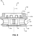
- the first to fifth chambers 31 - 35 in the shown embodiment are formed by a chamber insert 50 (see also Figs. 7 and 9 ).
- the chamber insert 50 is inserted into a central recess 54 formed in a housing body 52.
- the housing body 52 may be formed out of a single element and in particular made of plastic material or metal material.
- the chamber insert 50 preferably is formed out of several elements, or may be formed as a one-piece, again using plastic or metal material.
- the chamber insert 50 comprises a central passage 56 in which the valve spool 15 is seated.
- the chamber insert 50 itself seals against an inner surface 55 of the central recess 54.
- the single chambers namely the first chamber 31, the second chamber 32, the third chamber 33, the fourth chamber 34, and the fifth chamber 35 are formed by respective through-holes in the chamber insert 50.
- the chamber insert 50 comprises a first through-hole 61, which in this embodiment forms the first chamber 31, a second through-hole 62, which in this embodiment forms the second chamber 32, a third through-hole 63, which in this embodiment forms the third chamber 33, a fourth through-hole 64, which in this embodiment forms the fourth chamber 34, and finally a fifth through-hole 65, which in this embodiment forms the fifth chamber 35.
- the valve housing body 52 does not need to have specific recesses or the like which would form one of the chambers 31 - 35.
- the chambers 31 - 35 are simply formed by mounting the chamber insert 50 within the respective central recess 54. This is also the reason why the park release valve 10 of the present invention is called a valve of the spool-and-sleeve type.
- the chamber insert 50 forms a sleeve for the valve spool 15.
- ring seals are provided.
- a first ring seal 71 is provided between the first and second chambers 31, 32
- a second ring seal 72 is provided between the second chamber and third chamber
- a third ring seal 73 is provided between the third chamber 33 and fourth chamber 34
- a fourth ring seal 74 is provided between the fourth chamber 34 and fifth chamber 35.
- a first lip seal 76 and a second lip seal 78 are provided, to seal the first chamber 31 and fifth chamber 35, respectively, against the environment.
- the ring seals 71 - 74 and preferably also the lip seals 76, 78 are double acting, meaning that they seal at their radially outer surface against the inner surface 56 of the central recess 54. At their radially inner side they seal against the outer surface 18 of the valve spool 15.
- Each ring seal 71 - 74 may be formed as a single element or may also be formed from different parts.
- each ring seal 71 - 74 may comprise a radially outer ring seal and a radially inner ring seal which are separate.
- Figs. 5a to 5d specifically show the layout of Figs. 2a to 2c , however, in a construction as shown in Fig. 4 .
- valve spool 15 In this position, the valve spool 15 is in the uppermost position, the piston 40 is in the extended upper position (sixth chamber 36 is ventilated by truck supply pressure P1) and the second end 44 of the valve spool 15 is lifted out of the hollow portion 46 of piston 40.
- a position indicator 80 is provided at the push button 16.
- the position indicator 80 is fixed relative to the valve housing 12 and thus has different relative positions when the push button 16 moves. As the push button 16 is in the uppermost position in Fig. 5a , the position indicator 80 is retracted within the push button 16 and not easily visible from outside.
- valve spool 15 When now from the parking position the valve spool 15 is pushed using the push button 16 into the driving position V2 ( Fig. 5b ), push button 16 is moved down with respect to Fig. 5b and the position indicator 80 is flush with the upper surface of push button 16 as can be seen in Fig. 5b . This movement causes the valve spool 15 to move relative to the chamber insert 50 into a position which also is shown in Fig. 4 . In the driving position V2, as can be inferred from Fig.
- the supply port 1-1 needs to be in communication with the delivery port 2 for delivering supply pressure P1 through the park release valve 10 as braking pressure PB to the spring-loaded brakes 108a - 108d for ventilating spring-loaded brakes 108a - 108d and thus releasing them.
- Exhaust port 3 needs to be blocked, and also reservoir port 1-2 should be blocked.
- the operator or driver may push down the push button 16 further and into a position in which the position indicator 80 actually protrudes out of the push button 16, as shown in Fig. 5c .
- the position indicator 80 becomes a different color than the push button 16, it can easily be seen and determined by the operator that the park release valve 10 is in the release position.
- FIG. 7 now shows an exploded view of the chamber insert 50 and the valve spool 15.
- Chamber insert 50 in this embodiment is formed out of separate elements and stacked together. It should however also be understood that chamber insert 50 could be formed of a single element.
- Cage element 94 then acts together with the third sealing ring 73, onto which the third cage element 93 is placed.
- Second sealing ring 72, second cage element 92, first sealing ring 71, first cage element 91 and second lip seal 78 follow.
- a ring member 96 is placed at the first axial face 136 of the fifth cage 95 for holding the first lip seal 76 and the ring seal 77 in place.
- a topper member 97 is placed which holds all other elements in place.
- Topper member 97 is attached to the valve housing body 52 by a lid 140 (see Fig. 4 ) which is held in place by a screw 142.
Landscapes
- Engineering & Computer Science (AREA)
- Transportation (AREA)
- Mechanical Engineering (AREA)
- Valves And Accessory Devices For Braking Systems (AREA)
Applications Claiming Priority (1)
| Application Number | Priority Date | Filing Date | Title |
|---|---|---|---|
| IN201811026350 | 2018-07-13 |
Publications (2)
| Publication Number | Publication Date |
|---|---|
| EP3611065A1 true EP3611065A1 (de) | 2020-02-19 |
| EP3611065B1 EP3611065B1 (de) | 2021-02-24 |
Family
ID=67225979
Family Applications (1)
| Application Number | Title | Priority Date | Filing Date |
|---|---|---|---|
| EP19182759.1A Active EP3611065B1 (de) | 2018-07-13 | 2019-06-27 | Parksperrenlöseventil einfache anordnung aus 4-wege-3-positionen (4/3-ventil)-spule (stange) und hülsenventil mit öffnungsfunktion |
Country Status (2)
| Country | Link |
|---|---|
| EP (1) | EP3611065B1 (de) |
| CN (1) | CN110712638B (de) |
Cited By (1)
| Publication number | Priority date | Publication date | Assignee | Title |
|---|---|---|---|---|
| SE2050979A1 (en) * | 2020-08-26 | 2022-02-27 | Scania Cv Ab | Emergency brake unit for a vehicle, vehicle including such an emergency brake unit and a method of controlling an emergency brake unit |
Families Citing this family (1)
| Publication number | Priority date | Publication date | Assignee | Title |
|---|---|---|---|---|
| CN112277907B (zh) * | 2020-11-02 | 2021-07-20 | 安徽江淮汽车集团股份有限公司 | 驾驶室可卧断气刹操纵装置 |
Citations (9)
| Publication number | Priority date | Publication date | Assignee | Title |
|---|---|---|---|---|
| GB2310695A (en) * | 1996-03-01 | 1997-09-03 | Pownall Security Systems Ltd | Trailer park brake system |
| DE19818982C2 (de) | 1998-04-28 | 2001-05-17 | Knorr Bremse Systeme | Park- und Rangierventil für Anhängerfahrzeuge mit einer Federspeicher-Feststellbremse |
| CA2502129A1 (en) * | 2004-05-03 | 2005-11-03 | Bendix Commercial Vehicle Systems Llc | Dash control valve with two step function for park release |
| DE19854881B4 (de) | 1998-04-28 | 2008-07-31 | Knorr-Bremse Systeme für Nutzfahrzeuge GmbH | Park- und Rangierventil für Anhängefahrzeuge mit einer Federspeicher-Feststellbremse |
| EP2058187A2 (de) | 2007-11-12 | 2009-05-13 | Haldex Brake Products GmbH | Feststellbremsventil für eine Steueranlage für Kraftfahrzeug- Anhänger mit Betriebsbremse, Feststellbremse und Luftfederung |
| EP2426021A1 (de) * | 2010-09-06 | 2012-03-07 | Haldex Brake Products GmbH | Parkventil für einen Nutzfahrzeug-Anhänger |
| DE202015105790U1 (de) * | 2015-10-30 | 2017-01-31 | Haldex Brake Products Aktiebolag | Ventilbaugruppe und Verwendung derselben |
| EP3228512A1 (de) | 2016-04-05 | 2017-10-11 | WABCO GmbH | Park-löse-ventil für ein anhängefahrzeug |
| US20170370485A1 (en) * | 2016-06-27 | 2017-12-28 | Travis Victor Dean Loewen | Multi-Pilot Variable Pressure Relay Valve |
Family Cites Families (4)
| Publication number | Priority date | Publication date | Assignee | Title |
|---|---|---|---|---|
| US3841714A (en) * | 1973-05-02 | 1974-10-15 | Midland Ross Corp | Parking brake control |
| US4158470A (en) * | 1978-02-16 | 1979-06-19 | The Bendix Corporation | Spring brake hold-off system |
| US7722131B2 (en) * | 2006-02-02 | 2010-05-25 | White Drive Products, Inc. | Control component for a spring applied-pressure released hydraulic brake and hydraulic motor |
| DE102011053529B4 (de) * | 2011-09-12 | 2014-06-26 | Haldex Brake Products Gmbh | Ventilbaugruppe für eine Anhängerbremsanlage |
-
2019
- 2019-06-27 EP EP19182759.1A patent/EP3611065B1/de active Active
- 2019-07-11 CN CN201910624443.0A patent/CN110712638B/zh active Active
Patent Citations (9)
| Publication number | Priority date | Publication date | Assignee | Title |
|---|---|---|---|---|
| GB2310695A (en) * | 1996-03-01 | 1997-09-03 | Pownall Security Systems Ltd | Trailer park brake system |
| DE19818982C2 (de) | 1998-04-28 | 2001-05-17 | Knorr Bremse Systeme | Park- und Rangierventil für Anhängerfahrzeuge mit einer Federspeicher-Feststellbremse |
| DE19854881B4 (de) | 1998-04-28 | 2008-07-31 | Knorr-Bremse Systeme für Nutzfahrzeuge GmbH | Park- und Rangierventil für Anhängefahrzeuge mit einer Federspeicher-Feststellbremse |
| CA2502129A1 (en) * | 2004-05-03 | 2005-11-03 | Bendix Commercial Vehicle Systems Llc | Dash control valve with two step function for park release |
| EP2058187A2 (de) | 2007-11-12 | 2009-05-13 | Haldex Brake Products GmbH | Feststellbremsventil für eine Steueranlage für Kraftfahrzeug- Anhänger mit Betriebsbremse, Feststellbremse und Luftfederung |
| EP2426021A1 (de) * | 2010-09-06 | 2012-03-07 | Haldex Brake Products GmbH | Parkventil für einen Nutzfahrzeug-Anhänger |
| DE202015105790U1 (de) * | 2015-10-30 | 2017-01-31 | Haldex Brake Products Aktiebolag | Ventilbaugruppe und Verwendung derselben |
| EP3228512A1 (de) | 2016-04-05 | 2017-10-11 | WABCO GmbH | Park-löse-ventil für ein anhängefahrzeug |
| US20170370485A1 (en) * | 2016-06-27 | 2017-12-28 | Travis Victor Dean Loewen | Multi-Pilot Variable Pressure Relay Valve |
Cited By (2)
| Publication number | Priority date | Publication date | Assignee | Title |
|---|---|---|---|---|
| SE2050979A1 (en) * | 2020-08-26 | 2022-02-27 | Scania Cv Ab | Emergency brake unit for a vehicle, vehicle including such an emergency brake unit and a method of controlling an emergency brake unit |
| SE544528C2 (en) * | 2020-08-26 | 2022-07-05 | Scania Cv Ab | Emergency brake unit for a vehicle, vehicle including such an emergency brake unit and a method of controlling an emergency brake unit |
Also Published As
| Publication number | Publication date |
|---|---|
| CN110712638B (zh) | 2022-01-11 |
| EP3611065B1 (de) | 2021-02-24 |
| CN110712638A (zh) | 2020-01-21 |
Similar Documents
| Publication | Publication Date | Title |
|---|---|---|
| EP3611065B1 (de) | Parksperrenlöseventil einfache anordnung aus 4-wege-3-positionen (4/3-ventil)-spule (stange) und hülsenventil mit öffnungsfunktion | |
| US4121873A (en) | Vehicle air brake system with emergency features | |
| JPH07508483A (ja) | 流体作動式ブレーキアクチュエータのためのスプリング室隔離システム | |
| CA2385201C (en) | Two step park release valve | |
| KR20080036592A (ko) | 상용 차량용 공압 제동 시스템 | |
| CA2011119C (en) | Detent mechanism for a control valve | |
| US5904228A (en) | Brake control system and related method | |
| DE1680232A1 (de) | Bremsausloeser | |
| US4907842A (en) | Vehicle air brake system and valves for it | |
| US3269409A (en) | Check valve for use with a master cylinder | |
| GB2203196A (en) | Hydraulic actuator assembly | |
| US3892444A (en) | Pneumatic brake system | |
| CN108602503B (zh) | 用于挂车的驻车释放阀 | |
| US4191428A (en) | Air brake system with pressure holding valve | |
| US5046788A (en) | Pressure piloted release valve | |
| US3370601A (en) | Valve for controlling the rate of movement of a fluid powered motor unit | |
| GB2175362A (en) | Anti-skid vehicle braking system | |
| US4936346A (en) | Detent mechanism for a control valve | |
| US4088374A (en) | Air pressure brake arrangement for tractor and semi-trailer combinations | |
| EP0090546A2 (de) | Notbremssystem | |
| US4119351A (en) | Air brake system with pressure holding valve | |
| US4472942A (en) | Tandem brake master cylinder with anti bottoming system | |
| GB1565316A (en) | Hydraulic brake booster | |
| CS262667B2 (en) | Hydraulic antiskid brake system vehicles | |
| US2992535A (en) | Hydraulic protector for brakes |
Legal Events
| Date | Code | Title | Description |
|---|---|---|---|
| PUAI | Public reference made under article 153(3) epc to a published international application that has entered the european phase |
Free format text: ORIGINAL CODE: 0009012 |
|
| STAA | Information on the status of an ep patent application or granted ep patent |
Free format text: STATUS: THE APPLICATION HAS BEEN PUBLISHED |
|
| AK | Designated contracting states |
Kind code of ref document: A1 Designated state(s): AL AT BE BG CH CY CZ DE DK EE ES FI FR GB GR HR HU IE IS IT LI LT LU LV MC MK MT NL NO PL PT RO RS SE SI SK SM TR |
|
| AX | Request for extension of the european patent |
Extension state: BA ME |
|
| STAA | Information on the status of an ep patent application or granted ep patent |
Free format text: STATUS: REQUEST FOR EXAMINATION WAS MADE |
|
| 17P | Request for examination filed |
Effective date: 20200819 |
|
| RBV | Designated contracting states (corrected) |
Designated state(s): AL AT BE BG CH CY CZ DE DK EE ES FI FR GB GR HR HU IE IS IT LI LT LU LV MC MK MT NL NO PL PT RO RS SE SI SK SM TR |
|
| GRAP | Despatch of communication of intention to grant a patent |
Free format text: ORIGINAL CODE: EPIDOSNIGR1 |
|
| STAA | Information on the status of an ep patent application or granted ep patent |
Free format text: STATUS: GRANT OF PATENT IS INTENDED |
|
| INTG | Intention to grant announced |
Effective date: 20201021 |
|
| GRAS | Grant fee paid |
Free format text: ORIGINAL CODE: EPIDOSNIGR3 |
|
| GRAA | (expected) grant |
Free format text: ORIGINAL CODE: 0009210 |
|
| STAA | Information on the status of an ep patent application or granted ep patent |
Free format text: STATUS: THE PATENT HAS BEEN GRANTED |
|
| AK | Designated contracting states |
Kind code of ref document: B1 Designated state(s): AL AT BE BG CH CY CZ DE DK EE ES FI FR GB GR HR HU IE IS IT LI LT LU LV MC MK MT NL NO PL PT RO RS SE SI SK SM TR |
|
| REG | Reference to a national code |
Ref country code: CH Ref legal event code: EP |
|
| REG | Reference to a national code |
Ref country code: AT Ref legal event code: REF Ref document number: 1364068 Country of ref document: AT Kind code of ref document: T Effective date: 20210315 |
|
| REG | Reference to a national code |
Ref country code: IE Ref legal event code: FG4D |
|
| REG | Reference to a national code |
Ref country code: DE Ref legal event code: R096 Ref document number: 602019002735 Country of ref document: DE |
|
| RAP4 | Party data changed (patent owner data changed or rights of a patent transferred) |
Owner name: ZF CV SYSTEMS EUROPE BV |
|
| REG | Reference to a national code |
Ref country code: LT Ref legal event code: MG9D |
|
| REG | Reference to a national code |
Ref country code: NL Ref legal event code: MP Effective date: 20210224 |
|
| PG25 | Lapsed in a contracting state [announced via postgrant information from national office to epo] |
Ref country code: HR Free format text: LAPSE BECAUSE OF FAILURE TO SUBMIT A TRANSLATION OF THE DESCRIPTION OR TO PAY THE FEE WITHIN THE PRESCRIBED TIME-LIMIT Effective date: 20210224 Ref country code: BG Free format text: LAPSE BECAUSE OF FAILURE TO SUBMIT A TRANSLATION OF THE DESCRIPTION OR TO PAY THE FEE WITHIN THE PRESCRIBED TIME-LIMIT Effective date: 20210524 Ref country code: GR Free format text: LAPSE BECAUSE OF FAILURE TO SUBMIT A TRANSLATION OF THE DESCRIPTION OR TO PAY THE FEE WITHIN THE PRESCRIBED TIME-LIMIT Effective date: 20210525 Ref country code: FI Free format text: LAPSE BECAUSE OF FAILURE TO SUBMIT A TRANSLATION OF THE DESCRIPTION OR TO PAY THE FEE WITHIN THE PRESCRIBED TIME-LIMIT Effective date: 20210224 Ref country code: PT Free format text: LAPSE BECAUSE OF FAILURE TO SUBMIT A TRANSLATION OF THE DESCRIPTION OR TO PAY THE FEE WITHIN THE PRESCRIBED TIME-LIMIT Effective date: 20210624 Ref country code: NO Free format text: LAPSE BECAUSE OF FAILURE TO SUBMIT A TRANSLATION OF THE DESCRIPTION OR TO PAY THE FEE WITHIN THE PRESCRIBED TIME-LIMIT Effective date: 20210524 Ref country code: LT Free format text: LAPSE BECAUSE OF FAILURE TO SUBMIT A TRANSLATION OF THE DESCRIPTION OR TO PAY THE FEE WITHIN THE PRESCRIBED TIME-LIMIT Effective date: 20210224 |
|
| REG | Reference to a national code |
Ref country code: AT Ref legal event code: MK05 Ref document number: 1364068 Country of ref document: AT Kind code of ref document: T Effective date: 20210224 |
|
| PG25 | Lapsed in a contracting state [announced via postgrant information from national office to epo] |
Ref country code: LV Free format text: LAPSE BECAUSE OF FAILURE TO SUBMIT A TRANSLATION OF THE DESCRIPTION OR TO PAY THE FEE WITHIN THE PRESCRIBED TIME-LIMIT Effective date: 20210224 Ref country code: NL Free format text: LAPSE BECAUSE OF FAILURE TO SUBMIT A TRANSLATION OF THE DESCRIPTION OR TO PAY THE FEE WITHIN THE PRESCRIBED TIME-LIMIT Effective date: 20210224 Ref country code: PL Free format text: LAPSE BECAUSE OF FAILURE TO SUBMIT A TRANSLATION OF THE DESCRIPTION OR TO PAY THE FEE WITHIN THE PRESCRIBED TIME-LIMIT Effective date: 20210224 Ref country code: SE Free format text: LAPSE BECAUSE OF FAILURE TO SUBMIT A TRANSLATION OF THE DESCRIPTION OR TO PAY THE FEE WITHIN THE PRESCRIBED TIME-LIMIT Effective date: 20210224 Ref country code: RS Free format text: LAPSE BECAUSE OF FAILURE TO SUBMIT A TRANSLATION OF THE DESCRIPTION OR TO PAY THE FEE WITHIN THE PRESCRIBED TIME-LIMIT Effective date: 20210224 |
|
| REG | Reference to a national code |
Ref country code: DE Ref legal event code: R081 Ref document number: 602019002735 Country of ref document: DE Owner name: ZF CV SYSTEMS EUROPE BV, BE Free format text: FORMER OWNER: WABCO EUROPE BVBA, BRUESSEL, BE |
|
| PG25 | Lapsed in a contracting state [announced via postgrant information from national office to epo] |
Ref country code: IS Free format text: LAPSE BECAUSE OF FAILURE TO SUBMIT A TRANSLATION OF THE DESCRIPTION OR TO PAY THE FEE WITHIN THE PRESCRIBED TIME-LIMIT Effective date: 20210624 |
|
| PG25 | Lapsed in a contracting state [announced via postgrant information from national office to epo] |
Ref country code: AT Free format text: LAPSE BECAUSE OF FAILURE TO SUBMIT A TRANSLATION OF THE DESCRIPTION OR TO PAY THE FEE WITHIN THE PRESCRIBED TIME-LIMIT Effective date: 20210224 Ref country code: SM Free format text: LAPSE BECAUSE OF FAILURE TO SUBMIT A TRANSLATION OF THE DESCRIPTION OR TO PAY THE FEE WITHIN THE PRESCRIBED TIME-LIMIT Effective date: 20210224 Ref country code: CZ Free format text: LAPSE BECAUSE OF FAILURE TO SUBMIT A TRANSLATION OF THE DESCRIPTION OR TO PAY THE FEE WITHIN THE PRESCRIBED TIME-LIMIT Effective date: 20210224 Ref country code: EE Free format text: LAPSE BECAUSE OF FAILURE TO SUBMIT A TRANSLATION OF THE DESCRIPTION OR TO PAY THE FEE WITHIN THE PRESCRIBED TIME-LIMIT Effective date: 20210224 |
|
| REG | Reference to a national code |
Ref country code: DE Ref legal event code: R097 Ref document number: 602019002735 Country of ref document: DE |
|
| PG25 | Lapsed in a contracting state [announced via postgrant information from national office to epo] |
Ref country code: DK Free format text: LAPSE BECAUSE OF FAILURE TO SUBMIT A TRANSLATION OF THE DESCRIPTION OR TO PAY THE FEE WITHIN THE PRESCRIBED TIME-LIMIT Effective date: 20210224 Ref country code: RO Free format text: LAPSE BECAUSE OF FAILURE TO SUBMIT A TRANSLATION OF THE DESCRIPTION OR TO PAY THE FEE WITHIN THE PRESCRIBED TIME-LIMIT Effective date: 20210224 Ref country code: SK Free format text: LAPSE BECAUSE OF FAILURE TO SUBMIT A TRANSLATION OF THE DESCRIPTION OR TO PAY THE FEE WITHIN THE PRESCRIBED TIME-LIMIT Effective date: 20210224 |
|
| PLBE | No opposition filed within time limit |
Free format text: ORIGINAL CODE: 0009261 |
|
| STAA | Information on the status of an ep patent application or granted ep patent |
Free format text: STATUS: NO OPPOSITION FILED WITHIN TIME LIMIT |
|
| PG25 | Lapsed in a contracting state [announced via postgrant information from national office to epo] |
Ref country code: ES Free format text: LAPSE BECAUSE OF FAILURE TO SUBMIT A TRANSLATION OF THE DESCRIPTION OR TO PAY THE FEE WITHIN THE PRESCRIBED TIME-LIMIT Effective date: 20210224 Ref country code: AL Free format text: LAPSE BECAUSE OF FAILURE TO SUBMIT A TRANSLATION OF THE DESCRIPTION OR TO PAY THE FEE WITHIN THE PRESCRIBED TIME-LIMIT Effective date: 20210224 Ref country code: MC Free format text: LAPSE BECAUSE OF FAILURE TO SUBMIT A TRANSLATION OF THE DESCRIPTION OR TO PAY THE FEE WITHIN THE PRESCRIBED TIME-LIMIT Effective date: 20210224 |
|
| 26N | No opposition filed |
Effective date: 20211125 |
|
| PG25 | Lapsed in a contracting state [announced via postgrant information from national office to epo] |
Ref country code: SI Free format text: LAPSE BECAUSE OF FAILURE TO SUBMIT A TRANSLATION OF THE DESCRIPTION OR TO PAY THE FEE WITHIN THE PRESCRIBED TIME-LIMIT Effective date: 20210224 |
|
| REG | Reference to a national code |
Ref country code: BE Ref legal event code: MM Effective date: 20210630 |
|
| PG25 | Lapsed in a contracting state [announced via postgrant information from national office to epo] |
Ref country code: LU Free format text: LAPSE BECAUSE OF NON-PAYMENT OF DUE FEES Effective date: 20210627 |
|
| PG25 | Lapsed in a contracting state [announced via postgrant information from national office to epo] |
Ref country code: IT Free format text: LAPSE BECAUSE OF FAILURE TO SUBMIT A TRANSLATION OF THE DESCRIPTION OR TO PAY THE FEE WITHIN THE PRESCRIBED TIME-LIMIT Effective date: 20210224 Ref country code: IE Free format text: LAPSE BECAUSE OF NON-PAYMENT OF DUE FEES Effective date: 20210627 |
|
| PG25 | Lapsed in a contracting state [announced via postgrant information from national office to epo] |
Ref country code: IS Free format text: LAPSE BECAUSE OF FAILURE TO SUBMIT A TRANSLATION OF THE DESCRIPTION OR TO PAY THE FEE WITHIN THE PRESCRIBED TIME-LIMIT Effective date: 20210624 |
|
| PG25 | Lapsed in a contracting state [announced via postgrant information from national office to epo] |
Ref country code: BE Free format text: LAPSE BECAUSE OF NON-PAYMENT OF DUE FEES Effective date: 20210630 |
|
| REG | Reference to a national code |
Ref country code: CH Ref legal event code: PL |
|
| PG25 | Lapsed in a contracting state [announced via postgrant information from national office to epo] |
Ref country code: LI Free format text: LAPSE BECAUSE OF NON-PAYMENT OF DUE FEES Effective date: 20220630 Ref country code: CH Free format text: LAPSE BECAUSE OF NON-PAYMENT OF DUE FEES Effective date: 20220630 |
|
| PG25 | Lapsed in a contracting state [announced via postgrant information from national office to epo] |
Ref country code: CY Free format text: LAPSE BECAUSE OF FAILURE TO SUBMIT A TRANSLATION OF THE DESCRIPTION OR TO PAY THE FEE WITHIN THE PRESCRIBED TIME-LIMIT Effective date: 20210224 |
|
| P01 | Opt-out of the competence of the unified patent court (upc) registered |
Effective date: 20230528 |
|
| PG25 | Lapsed in a contracting state [announced via postgrant information from national office to epo] |
Ref country code: HU Free format text: LAPSE BECAUSE OF FAILURE TO SUBMIT A TRANSLATION OF THE DESCRIPTION OR TO PAY THE FEE WITHIN THE PRESCRIBED TIME-LIMIT; INVALID AB INITIO Effective date: 20190627 |
|
| PGFP | Annual fee paid to national office [announced via postgrant information from national office to epo] |
Ref country code: FR Payment date: 20230622 Year of fee payment: 5 Ref country code: DE Payment date: 20230630 Year of fee payment: 5 |
|
| PGFP | Annual fee paid to national office [announced via postgrant information from national office to epo] |
Ref country code: GB Payment date: 20230622 Year of fee payment: 5 |
|
| PG25 | Lapsed in a contracting state [announced via postgrant information from national office to epo] |
Ref country code: MK Free format text: LAPSE BECAUSE OF FAILURE TO SUBMIT A TRANSLATION OF THE DESCRIPTION OR TO PAY THE FEE WITHIN THE PRESCRIBED TIME-LIMIT Effective date: 20210224 |