EP3611045A1 - Electricity storage device controller, electric system, and construction machine - Google Patents
Electricity storage device controller, electric system, and construction machine Download PDFInfo
- Publication number
- EP3611045A1 EP3611045A1 EP18784049.1A EP18784049A EP3611045A1 EP 3611045 A1 EP3611045 A1 EP 3611045A1 EP 18784049 A EP18784049 A EP 18784049A EP 3611045 A1 EP3611045 A1 EP 3611045A1
- Authority
- EP
- European Patent Office
- Prior art keywords
- storage device
- electricity storage
- relay
- controller
- electric motor
- Prior art date
- Legal status (The legal status is an assumption and is not a legal conclusion. Google has not performed a legal analysis and makes no representation as to the accuracy of the status listed.)
- Granted
Links
Images


Classifications
-
- B—PERFORMING OPERATIONS; TRANSPORTING
- B60—VEHICLES IN GENERAL
- B60K—ARRANGEMENT OR MOUNTING OF PROPULSION UNITS OR OF TRANSMISSIONS IN VEHICLES; ARRANGEMENT OR MOUNTING OF PLURAL DIVERSE PRIME-MOVERS IN VEHICLES; AUXILIARY DRIVES FOR VEHICLES; INSTRUMENTATION OR DASHBOARDS FOR VEHICLES; ARRANGEMENTS IN CONNECTION WITH COOLING, AIR INTAKE, GAS EXHAUST OR FUEL SUPPLY OF PROPULSION UNITS IN VEHICLES
- B60K6/00—Arrangement or mounting of plural diverse prime-movers for mutual or common propulsion, e.g. hybrid propulsion systems comprising electric motors and internal combustion engines
- B60K6/20—Arrangement or mounting of plural diverse prime-movers for mutual or common propulsion, e.g. hybrid propulsion systems comprising electric motors and internal combustion engines the prime-movers consisting of electric motors and internal combustion engines, e.g. HEVs
- B60K6/22—Arrangement or mounting of plural diverse prime-movers for mutual or common propulsion, e.g. hybrid propulsion systems comprising electric motors and internal combustion engines the prime-movers consisting of electric motors and internal combustion engines, e.g. HEVs characterised by apparatus, components or means specially adapted for HEVs
- B60K6/26—Arrangement or mounting of plural diverse prime-movers for mutual or common propulsion, e.g. hybrid propulsion systems comprising electric motors and internal combustion engines the prime-movers consisting of electric motors and internal combustion engines, e.g. HEVs characterised by apparatus, components or means specially adapted for HEVs characterised by the motors or the generators
-
- B—PERFORMING OPERATIONS; TRANSPORTING
- B60—VEHICLES IN GENERAL
- B60L—PROPULSION OF ELECTRICALLY-PROPELLED VEHICLES; SUPPLYING ELECTRIC POWER FOR AUXILIARY EQUIPMENT OF ELECTRICALLY-PROPELLED VEHICLES; ELECTRODYNAMIC BRAKE SYSTEMS FOR VEHICLES IN GENERAL; MAGNETIC SUSPENSION OR LEVITATION FOR VEHICLES; MONITORING OPERATING VARIABLES OF ELECTRICALLY-PROPELLED VEHICLES; ELECTRIC SAFETY DEVICES FOR ELECTRICALLY-PROPELLED VEHICLES
- B60L3/00—Electric devices on electrically-propelled vehicles for safety purposes; Monitoring operating variables, e.g. speed, deceleration or energy consumption
- B60L3/04—Cutting off the power supply under fault conditions
-
- B—PERFORMING OPERATIONS; TRANSPORTING
- B60—VEHICLES IN GENERAL
- B60K—ARRANGEMENT OR MOUNTING OF PROPULSION UNITS OR OF TRANSMISSIONS IN VEHICLES; ARRANGEMENT OR MOUNTING OF PLURAL DIVERSE PRIME-MOVERS IN VEHICLES; AUXILIARY DRIVES FOR VEHICLES; INSTRUMENTATION OR DASHBOARDS FOR VEHICLES; ARRANGEMENTS IN CONNECTION WITH COOLING, AIR INTAKE, GAS EXHAUST OR FUEL SUPPLY OF PROPULSION UNITS IN VEHICLES
- B60K6/00—Arrangement or mounting of plural diverse prime-movers for mutual or common propulsion, e.g. hybrid propulsion systems comprising electric motors and internal combustion engines
- B60K6/20—Arrangement or mounting of plural diverse prime-movers for mutual or common propulsion, e.g. hybrid propulsion systems comprising electric motors and internal combustion engines the prime-movers consisting of electric motors and internal combustion engines, e.g. HEVs
- B60K6/42—Arrangement or mounting of plural diverse prime-movers for mutual or common propulsion, e.g. hybrid propulsion systems comprising electric motors and internal combustion engines the prime-movers consisting of electric motors and internal combustion engines, e.g. HEVs characterised by the architecture of the hybrid electric vehicle
- B60K6/48—Parallel type
- B60K6/485—Motor-assist type
-
- B—PERFORMING OPERATIONS; TRANSPORTING
- B60—VEHICLES IN GENERAL
- B60L—PROPULSION OF ELECTRICALLY-PROPELLED VEHICLES; SUPPLYING ELECTRIC POWER FOR AUXILIARY EQUIPMENT OF ELECTRICALLY-PROPELLED VEHICLES; ELECTRODYNAMIC BRAKE SYSTEMS FOR VEHICLES IN GENERAL; MAGNETIC SUSPENSION OR LEVITATION FOR VEHICLES; MONITORING OPERATING VARIABLES OF ELECTRICALLY-PROPELLED VEHICLES; ELECTRIC SAFETY DEVICES FOR ELECTRICALLY-PROPELLED VEHICLES
- B60L3/00—Electric devices on electrically-propelled vehicles for safety purposes; Monitoring operating variables, e.g. speed, deceleration or energy consumption
- B60L3/0023—Detecting, eliminating, remedying or compensating for drive train abnormalities, e.g. failures within the drive train
- B60L3/0046—Detecting, eliminating, remedying or compensating for drive train abnormalities, e.g. failures within the drive train relating to electric energy storage systems, e.g. batteries or capacitors
-
- B—PERFORMING OPERATIONS; TRANSPORTING
- B60—VEHICLES IN GENERAL
- B60L—PROPULSION OF ELECTRICALLY-PROPELLED VEHICLES; SUPPLYING ELECTRIC POWER FOR AUXILIARY EQUIPMENT OF ELECTRICALLY-PROPELLED VEHICLES; ELECTRODYNAMIC BRAKE SYSTEMS FOR VEHICLES IN GENERAL; MAGNETIC SUSPENSION OR LEVITATION FOR VEHICLES; MONITORING OPERATING VARIABLES OF ELECTRICALLY-PROPELLED VEHICLES; ELECTRIC SAFETY DEVICES FOR ELECTRICALLY-PROPELLED VEHICLES
- B60L50/00—Electric propulsion with power supplied within the vehicle
- B60L50/10—Electric propulsion with power supplied within the vehicle using propulsion power supplied by engine-driven generators, e.g. generators driven by combustion engines
- B60L50/16—Electric propulsion with power supplied within the vehicle using propulsion power supplied by engine-driven generators, e.g. generators driven by combustion engines with provision for separate direct mechanical propulsion
-
- B—PERFORMING OPERATIONS; TRANSPORTING
- B60—VEHICLES IN GENERAL
- B60L—PROPULSION OF ELECTRICALLY-PROPELLED VEHICLES; SUPPLYING ELECTRIC POWER FOR AUXILIARY EQUIPMENT OF ELECTRICALLY-PROPELLED VEHICLES; ELECTRODYNAMIC BRAKE SYSTEMS FOR VEHICLES IN GENERAL; MAGNETIC SUSPENSION OR LEVITATION FOR VEHICLES; MONITORING OPERATING VARIABLES OF ELECTRICALLY-PROPELLED VEHICLES; ELECTRIC SAFETY DEVICES FOR ELECTRICALLY-PROPELLED VEHICLES
- B60L50/00—Electric propulsion with power supplied within the vehicle
- B60L50/50—Electric propulsion with power supplied within the vehicle using propulsion power supplied by batteries or fuel cells
- B60L50/51—Electric propulsion with power supplied within the vehicle using propulsion power supplied by batteries or fuel cells characterised by AC-motors
-
- B—PERFORMING OPERATIONS; TRANSPORTING
- B60—VEHICLES IN GENERAL
- B60W—CONJOINT CONTROL OF VEHICLE SUB-UNITS OF DIFFERENT TYPE OR DIFFERENT FUNCTION; CONTROL SYSTEMS SPECIALLY ADAPTED FOR HYBRID VEHICLES; ROAD VEHICLE DRIVE CONTROL SYSTEMS FOR PURPOSES NOT RELATED TO THE CONTROL OF A PARTICULAR SUB-UNIT
- B60W10/00—Conjoint control of vehicle sub-units of different type or different function
- B60W10/04—Conjoint control of vehicle sub-units of different type or different function including control of propulsion units
- B60W10/06—Conjoint control of vehicle sub-units of different type or different function including control of propulsion units including control of combustion engines
-
- B—PERFORMING OPERATIONS; TRANSPORTING
- B60—VEHICLES IN GENERAL
- B60W—CONJOINT CONTROL OF VEHICLE SUB-UNITS OF DIFFERENT TYPE OR DIFFERENT FUNCTION; CONTROL SYSTEMS SPECIALLY ADAPTED FOR HYBRID VEHICLES; ROAD VEHICLE DRIVE CONTROL SYSTEMS FOR PURPOSES NOT RELATED TO THE CONTROL OF A PARTICULAR SUB-UNIT
- B60W10/00—Conjoint control of vehicle sub-units of different type or different function
- B60W10/04—Conjoint control of vehicle sub-units of different type or different function including control of propulsion units
- B60W10/08—Conjoint control of vehicle sub-units of different type or different function including control of propulsion units including control of electric propulsion units, e.g. motors or generators
-
- B—PERFORMING OPERATIONS; TRANSPORTING
- B60—VEHICLES IN GENERAL
- B60W—CONJOINT CONTROL OF VEHICLE SUB-UNITS OF DIFFERENT TYPE OR DIFFERENT FUNCTION; CONTROL SYSTEMS SPECIALLY ADAPTED FOR HYBRID VEHICLES; ROAD VEHICLE DRIVE CONTROL SYSTEMS FOR PURPOSES NOT RELATED TO THE CONTROL OF A PARTICULAR SUB-UNIT
- B60W10/00—Conjoint control of vehicle sub-units of different type or different function
- B60W10/24—Conjoint control of vehicle sub-units of different type or different function including control of energy storage means
- B60W10/26—Conjoint control of vehicle sub-units of different type or different function including control of energy storage means for electrical energy, e.g. batteries or capacitors
-
- B—PERFORMING OPERATIONS; TRANSPORTING
- B60—VEHICLES IN GENERAL
- B60W—CONJOINT CONTROL OF VEHICLE SUB-UNITS OF DIFFERENT TYPE OR DIFFERENT FUNCTION; CONTROL SYSTEMS SPECIALLY ADAPTED FOR HYBRID VEHICLES; ROAD VEHICLE DRIVE CONTROL SYSTEMS FOR PURPOSES NOT RELATED TO THE CONTROL OF A PARTICULAR SUB-UNIT
- B60W10/00—Conjoint control of vehicle sub-units of different type or different function
- B60W10/30—Conjoint control of vehicle sub-units of different type or different function including control of auxiliary equipment, e.g. air-conditioning compressors or oil pumps
-
- B—PERFORMING OPERATIONS; TRANSPORTING
- B60—VEHICLES IN GENERAL
- B60W—CONJOINT CONTROL OF VEHICLE SUB-UNITS OF DIFFERENT TYPE OR DIFFERENT FUNCTION; CONTROL SYSTEMS SPECIALLY ADAPTED FOR HYBRID VEHICLES; ROAD VEHICLE DRIVE CONTROL SYSTEMS FOR PURPOSES NOT RELATED TO THE CONTROL OF A PARTICULAR SUB-UNIT
- B60W20/00—Control systems specially adapted for hybrid vehicles
- B60W20/50—Control strategies for responding to system failures, e.g. for fault diagnosis, failsafe operation or limp mode
-
- E—FIXED CONSTRUCTIONS
- E02—HYDRAULIC ENGINEERING; FOUNDATIONS; SOIL SHIFTING
- E02F—DREDGING; SOIL-SHIFTING
- E02F9/00—Component parts of dredgers or soil-shifting machines, not restricted to one of the kinds covered by groups E02F3/00 - E02F7/00
- E02F9/20—Drives; Control devices
-
- E—FIXED CONSTRUCTIONS
- E02—HYDRAULIC ENGINEERING; FOUNDATIONS; SOIL SHIFTING
- E02F—DREDGING; SOIL-SHIFTING
- E02F9/00—Component parts of dredgers or soil-shifting machines, not restricted to one of the kinds covered by groups E02F3/00 - E02F7/00
- E02F9/20—Drives; Control devices
- E02F9/2058—Electric or electro-mechanical or mechanical control devices of vehicle sub-units
- E02F9/2062—Control of propulsion units
- E02F9/2075—Control of propulsion units of the hybrid type
-
- E—FIXED CONSTRUCTIONS
- E02—HYDRAULIC ENGINEERING; FOUNDATIONS; SOIL SHIFTING
- E02F—DREDGING; SOIL-SHIFTING
- E02F9/00—Component parts of dredgers or soil-shifting machines, not restricted to one of the kinds covered by groups E02F3/00 - E02F7/00
- E02F9/20—Drives; Control devices
- E02F9/2058—Electric or electro-mechanical or mechanical control devices of vehicle sub-units
- E02F9/2091—Control of energy storage means for electrical energy, e.g. battery or capacitors
-
- E—FIXED CONSTRUCTIONS
- E02—HYDRAULIC ENGINEERING; FOUNDATIONS; SOIL SHIFTING
- E02F—DREDGING; SOIL-SHIFTING
- E02F9/00—Component parts of dredgers or soil-shifting machines, not restricted to one of the kinds covered by groups E02F3/00 - E02F7/00
- E02F9/26—Indicating devices
- E02F9/267—Diagnosing or detecting failure of vehicles
- E02F9/268—Diagnosing or detecting failure of vehicles with failure correction follow-up actions
-
- F—MECHANICAL ENGINEERING; LIGHTING; HEATING; WEAPONS; BLASTING
- F04—POSITIVE - DISPLACEMENT MACHINES FOR LIQUIDS; PUMPS FOR LIQUIDS OR ELASTIC FLUIDS
- F04B—POSITIVE-DISPLACEMENT MACHINES FOR LIQUIDS; PUMPS
- F04B49/00—Control, e.g. of pump delivery, or pump pressure of, or safety measures for, machines, pumps, or pumping installations, not otherwise provided for, or of interest apart from, groups F04B1/00 - F04B47/00
- F04B49/06—Control using electricity
-
- H—ELECTRICITY
- H02—GENERATION; CONVERSION OR DISTRIBUTION OF ELECTRIC POWER
- H02H—EMERGENCY PROTECTIVE CIRCUIT ARRANGEMENTS
- H02H3/00—Emergency protective circuit arrangements for automatic disconnection directly responsive to an undesired change from normal electric working condition with or without subsequent reconnection ; integrated protection
- H02H3/02—Details
- H02H3/05—Details with means for increasing reliability, e.g. redundancy arrangements
-
- H—ELECTRICITY
- H02—GENERATION; CONVERSION OR DISTRIBUTION OF ELECTRIC POWER
- H02H—EMERGENCY PROTECTIVE CIRCUIT ARRANGEMENTS
- H02H7/00—Emergency protective circuit arrangements specially adapted for specific types of electric machines or apparatus or for sectionalised protection of cable or line systems, and effecting automatic switching in the event of an undesired change from normal working conditions
- H02H7/18—Emergency protective circuit arrangements specially adapted for specific types of electric machines or apparatus or for sectionalised protection of cable or line systems, and effecting automatic switching in the event of an undesired change from normal working conditions for batteries; for accumulators
-
- H—ELECTRICITY
- H02—GENERATION; CONVERSION OR DISTRIBUTION OF ELECTRIC POWER
- H02J—ELECTRIC POWER NETWORKS; CIRCUIT ARRANGEMENTS OR SYSTEMS FOR SUPPLYING OR DISTRIBUTING ELECTRIC POWER; SYSTEMS FOR STORING ELECTRIC ENERGY
- H02J7/00—Circuit arrangements for charging or discharging batteries or for supplying loads from batteries
- H02J7/60—Circuit arrangements for charging or discharging batteries or for supplying loads from batteries including safety or protection arrangements
-
- H—ELECTRICITY
- H02—GENERATION; CONVERSION OR DISTRIBUTION OF ELECTRIC POWER
- H02J—ELECTRIC POWER NETWORKS; CIRCUIT ARRANGEMENTS OR SYSTEMS FOR SUPPLYING OR DISTRIBUTING ELECTRIC POWER; SYSTEMS FOR STORING ELECTRIC ENERGY
- H02J7/00—Circuit arrangements for charging or discharging batteries or for supplying loads from batteries
- H02J7/60—Circuit arrangements for charging or discharging batteries or for supplying loads from batteries including safety or protection arrangements
- H02J7/663—Circuit arrangements for charging or discharging batteries or for supplying loads from batteries including safety or protection arrangements using battery or load disconnect circuits
-
- B—PERFORMING OPERATIONS; TRANSPORTING
- B60—VEHICLES IN GENERAL
- B60L—PROPULSION OF ELECTRICALLY-PROPELLED VEHICLES; SUPPLYING ELECTRIC POWER FOR AUXILIARY EQUIPMENT OF ELECTRICALLY-PROPELLED VEHICLES; ELECTRODYNAMIC BRAKE SYSTEMS FOR VEHICLES IN GENERAL; MAGNETIC SUSPENSION OR LEVITATION FOR VEHICLES; MONITORING OPERATING VARIABLES OF ELECTRICALLY-PROPELLED VEHICLES; ELECTRIC SAFETY DEVICES FOR ELECTRICALLY-PROPELLED VEHICLES
- B60L2250/00—Driver interactions
- B60L2250/10—Driver interactions by alarm
-
- B—PERFORMING OPERATIONS; TRANSPORTING
- B60—VEHICLES IN GENERAL
- B60W—CONJOINT CONTROL OF VEHICLE SUB-UNITS OF DIFFERENT TYPE OR DIFFERENT FUNCTION; CONTROL SYSTEMS SPECIALLY ADAPTED FOR HYBRID VEHICLES; ROAD VEHICLE DRIVE CONTROL SYSTEMS FOR PURPOSES NOT RELATED TO THE CONTROL OF A PARTICULAR SUB-UNIT
- B60W2300/00—Indexing codes relating to the type of vehicle
- B60W2300/17—Construction vehicles, e.g. graders, excavators
-
- B—PERFORMING OPERATIONS; TRANSPORTING
- B60—VEHICLES IN GENERAL
- B60Y—INDEXING SCHEME RELATING TO ASPECTS CROSS-CUTTING VEHICLE TECHNOLOGY
- B60Y2200/00—Type of vehicle
- B60Y2200/40—Special vehicles
- B60Y2200/41—Construction vehicles, e.g. graders, excavators
-
- B—PERFORMING OPERATIONS; TRANSPORTING
- B60—VEHICLES IN GENERAL
- B60Y—INDEXING SCHEME RELATING TO ASPECTS CROSS-CUTTING VEHICLE TECHNOLOGY
- B60Y2200/00—Type of vehicle
- B60Y2200/90—Vehicles comprising electric prime movers
- B60Y2200/92—Hybrid vehicles
-
- H—ELECTRICITY
- H02—GENERATION; CONVERSION OR DISTRIBUTION OF ELECTRIC POWER
- H02J—ELECTRIC POWER NETWORKS; CIRCUIT ARRANGEMENTS OR SYSTEMS FOR SUPPLYING OR DISTRIBUTING ELECTRIC POWER; SYSTEMS FOR STORING ELECTRIC ENERGY
- H02J2105/00—Networks for supplying or distributing electric power characterised by their spatial reach or by the load
- H02J2105/30—Networks for supplying or distributing electric power characterised by their spatial reach or by the load the load networks being external to vehicles, i.e. exchanging power with vehicles
- H02J2105/33—Networks for supplying or distributing electric power characterised by their spatial reach or by the load the load networks being external to vehicles, i.e. exchanging power with vehicles exchanging power with road vehicles
- H02J2105/37—Networks for supplying or distributing electric power characterised by their spatial reach or by the load the load networks being external to vehicles, i.e. exchanging power with vehicles exchanging power with road vehicles exchanging power with electric vehicles [EV] or with hybrid electric vehicles [HEV]
-
- H—ELECTRICITY
- H02—GENERATION; CONVERSION OR DISTRIBUTION OF ELECTRIC POWER
- H02J—ELECTRIC POWER NETWORKS; CIRCUIT ARRANGEMENTS OR SYSTEMS FOR SUPPLYING OR DISTRIBUTING ELECTRIC POWER; SYSTEMS FOR STORING ELECTRIC ENERGY
- H02J7/00—Circuit arrangements for charging or discharging batteries or for supplying loads from batteries
- H02J7/14—Circuit arrangements for charging or discharging batteries or for supplying loads from batteries for charging batteries from dynamo-electric generators driven at varying speed, e.g. on vehicle
- H02J7/1469—Regulation of the charging current or voltage otherwise than by variation of field
- H02J7/1492—Regulation of the charging current or voltage otherwise than by variation of field by means of controlling devices between the generator output and the battery
-
- H—ELECTRICITY
- H02—GENERATION; CONVERSION OR DISTRIBUTION OF ELECTRIC POWER
- H02J—ELECTRIC POWER NETWORKS; CIRCUIT ARRANGEMENTS OR SYSTEMS FOR SUPPLYING OR DISTRIBUTING ELECTRIC POWER; SYSTEMS FOR STORING ELECTRIC ENERGY
- H02J7/00—Circuit arrangements for charging or discharging batteries or for supplying loads from batteries
- H02J7/60—Circuit arrangements for charging or discharging batteries or for supplying loads from batteries including safety or protection arrangements
- H02J7/65—Circuit arrangements for charging or discharging batteries or for supplying loads from batteries including safety or protection arrangements against overtemperature
-
- H—ELECTRICITY
- H02—GENERATION; CONVERSION OR DISTRIBUTION OF ELECTRIC POWER
- H02J—ELECTRIC POWER NETWORKS; CIRCUIT ARRANGEMENTS OR SYSTEMS FOR SUPPLYING OR DISTRIBUTING ELECTRIC POWER; SYSTEMS FOR STORING ELECTRIC ENERGY
- H02J7/00—Circuit arrangements for charging or discharging batteries or for supplying loads from batteries
- H02J7/60—Circuit arrangements for charging or discharging batteries or for supplying loads from batteries including safety or protection arrangements
- H02J7/663—Circuit arrangements for charging or discharging batteries or for supplying loads from batteries including safety or protection arrangements using battery or load disconnect circuits
- H02J7/667—Circuit arrangements for charging or discharging batteries or for supplying loads from batteries including safety or protection arrangements using battery or load disconnect circuits disconnection of loads if battery is not under charge, e.g. in vehicle if engine is not running
-
- Y—GENERAL TAGGING OF NEW TECHNOLOGICAL DEVELOPMENTS; GENERAL TAGGING OF CROSS-SECTIONAL TECHNOLOGIES SPANNING OVER SEVERAL SECTIONS OF THE IPC; TECHNICAL SUBJECTS COVERED BY FORMER USPC CROSS-REFERENCE ART COLLECTIONS [XRACs] AND DIGESTS
- Y02—TECHNOLOGIES OR APPLICATIONS FOR MITIGATION OR ADAPTATION AGAINST CLIMATE CHANGE
- Y02T—CLIMATE CHANGE MITIGATION TECHNOLOGIES RELATED TO TRANSPORTATION
- Y02T10/00—Road transport of goods or passengers
- Y02T10/60—Other road transportation technologies with climate change mitigation effect
- Y02T10/62—Hybrid vehicles
-
- Y—GENERAL TAGGING OF NEW TECHNOLOGICAL DEVELOPMENTS; GENERAL TAGGING OF CROSS-SECTIONAL TECHNOLOGIES SPANNING OVER SEVERAL SECTIONS OF THE IPC; TECHNICAL SUBJECTS COVERED BY FORMER USPC CROSS-REFERENCE ART COLLECTIONS [XRACs] AND DIGESTS
- Y02—TECHNOLOGIES OR APPLICATIONS FOR MITIGATION OR ADAPTATION AGAINST CLIMATE CHANGE
- Y02T—CLIMATE CHANGE MITIGATION TECHNOLOGIES RELATED TO TRANSPORTATION
- Y02T10/00—Road transport of goods or passengers
- Y02T10/60—Other road transportation technologies with climate change mitigation effect
- Y02T10/70—Energy storage systems for electromobility, e.g. batteries
-
- Y—GENERAL TAGGING OF NEW TECHNOLOGICAL DEVELOPMENTS; GENERAL TAGGING OF CROSS-SECTIONAL TECHNOLOGIES SPANNING OVER SEVERAL SECTIONS OF THE IPC; TECHNICAL SUBJECTS COVERED BY FORMER USPC CROSS-REFERENCE ART COLLECTIONS [XRACs] AND DIGESTS
- Y02—TECHNOLOGIES OR APPLICATIONS FOR MITIGATION OR ADAPTATION AGAINST CLIMATE CHANGE
- Y02T—CLIMATE CHANGE MITIGATION TECHNOLOGIES RELATED TO TRANSPORTATION
- Y02T10/00—Road transport of goods or passengers
- Y02T10/60—Other road transportation technologies with climate change mitigation effect
- Y02T10/7072—Electromobility specific charging systems or methods for batteries, ultracapacitors, supercapacitors or double-layer capacitors
Definitions
- the present invention relates to an electricity storage device controller, an electric system provided with the electricity storage device controller and a construction machine on which the electric system is mounted.
- Patent Document 1 discloses the technique on disconnection of a relay at the vehicle stop request in a motor/generator and a high voltage circuit of an electric vehicle.
- Patent Document 2 discloses the technique on disconnection of a relay at the system main relay disconnection request due to a hybrid system failure.
- the motorization of the power source can be achieved by using an electricity storage device storing power as the power source and driving an electric motor mechanically connected to a driven body with the power supplied from the electricity storage device.
- the electricity storage device is provided with a plurality of capacitors electrically connected in series, in parallel, or in series and in parallel.
- a secondary cell such as a lithium-ion cell, a lead cell or a nickel-hydrogen cell is used in the capacitor.
- adoption of the lithium-ion cell high in output of energy and in volumetric density in capacity has spread as the mainstream.
- the capacitor For continuing to safely use of the electricity storage device over a long period of time, the capacitor is required to be not used over the use range. That is, it is required to control charge/discharge of the capacitor in such a manner that a voltage, a charge/discharge current, a temperature, a charging state, a degradation state and the like of the capacitor are monitored to prevent the capacitor from leading to an abnormal state such as overcharge, over-discharge or an overtemperature. Therefore, the electricity storage device is provided with a controller configured to manage the aforementioned monitoring and control.
- a relay is provided in the electrical circuit between the electricity storage device and the electric motor, as described in Patent Document 1 for example.
- the relay can input or disconnect a contact point by controlling an operating current (an excitation current flowing in an excitation coil), as described in Patent Document 2.
- the operating current of the relay is controlled by a single control system. Therefore, in a case where the control system controlling the operating current in the relay is in failure or erroneously operated, the relay is not normally operated and the electricity storage device is not disconnected electrically from the electric motor side, possibly leading the capacitor to the abnormal state such as overcharge, over-discharge or an overtemperature.
- one of the problems to be solved by the present invention is to improve certainty on the circuit disconnection by the relay.
- One of the problems can be solved in such a manner that a relay control section configured to control supply and stop of an operating current in a relay is provided in each of at least two controllers and the supply or stop of the operating current in the relay can be achieved by the relay control section in each of the controllers.
- the supply or the stop of the operating current in the relay by the relay control section in one of the controllers can be achieved without any relation to the supply or stop of the operating current in the relay by the relay control section in the other of the controllers.
- the supply or the stop of the operating current in the relay by the relay control section by the one of the controllers is achieved after a predetermined time has elapsed from a point when the supply or stop of the operating current in the relay is required, for example, a time until the current flowing between the electricity storage device and the electric motor becomes in a zero state by the disconnection of the relay or a time until the supply of the operating current in the relay by the relay control section in the other of the controllers is stopped has elapsed.
- a construction machine includes: an electric motor; a hydraulic pump driven by the electric motor; a hydraulic device driven by pressurized oil delivered from the hydraulic pump; an electricity storage device that supplies power to the electric motor; an inverter provided between the electricity storage device and the electric motor to convert the power; a main controller that controls the hydraulic pump and the hydraulic device; an electricity storage device controller that controls the electricity storage device; an equipment controller that controls the electric motor, the inverter and the electricity storage device controller; and a relay connecting or disconnecting an electrical circuit to which the inverter and the electricity storage device are connected, characterized in that: the equipment controller and the electricity storage device controller each include an excitation current control section that controls supply and stop of an excitation current in the relay.
- an electric system includes: an electric motor driving a driven body; an electricity storage device that supplies power to the electric motor; an inverter provided between the electric motor and the electricity storage device to convert the power supplied from the electricity storage device and supply the converted power to the electric motor; a relay provided between the electricity storage device and the inverter to electrically connect or disconnect the electricity storage device and the inverter; an electricity storage device controller that manages a state of the electricity storage device; an upper controller that communicates with the electricity storage device controller, characterized in that: the electricity storage device controller and the upper controller each include a relay control section that controls supply and stop of an operating current in the relay.
- an electricity storage device controller in an electricity storage device that is connected electrically via a relay to an inverter and supplies power via the inverter to an electric motor driving a driven body, includes: an electricity storage device abnormal state notifying section configured to, when the electricity storage device becomes in an abnormal state of electrically disconnecting the electricity storage device and the inverter by the relay, notify an upper controller provided with a relay control section that controls supply and stop of an operating current in the relay of the abnormal state of the electricity storage device; and a relay control section configured to, when the electricity storage device becomes in the abnormal state of electrically disconnecting the electricity storage device and the inverter by the relay, stop the supply of the operating current in the relay with no relation to whether or not the supply of the operating current in the relay is stopped by the upper controller notifying the abnormal state of the electricity storage device.
- the equipment controller and the electricity storage device controller each include the excitation current control section (the relay control section) . That is, the supply and the stop of the excitation current in the relay can be controlled by the excitation current control section in the equipment controller and also by the excitation current control section in the electricity storage device controller. Therefore, even when one controller of the equipment controller and the electricity storage device controller is in failure or is erroneously operated, it is possible to disconnect the relay by stopping the excitation current in the relay with the excitation current control section of the other controller. Accordingly, it is possible to improve the certainty of the stop of the excitation current in the relay, that is, the certainty of the disconnection of the relay. As a result, it is possible to improve the safety of the mounted equipment and the vehicle body in the construction machine.
- the excitation current control section the relay control section
- the present invention can be applied to various kinds of hybrid construction machines such as a hybrid wheel loader or a hybrid dump truck, using power of a hydraulic pump driven by an electric motor connected to an electricity storage device and an engine as a power source.
- the present invention can be applied to various kinds of electric construction machines using an electricity storage device as a power source, further, various kinds of industrial machines composed of the similar equipment structure.
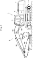
- Fig. 1 to Fig. 8 show a first embodiment of the present invention.
- a hybrid hydraulic excavator 1 (hereinafter, referred to as "hydraulic excavator 1") is provided with an engine 11 and an electric motor 15, which will be described later.
- the hydraulic excavator 1 includes an automotive lower traveling structure 2 of a crawler type, a revolving device 3 that is provided on the lower traveling structure 2, an upper revolving structure 4 that is mounted through the revolving device 3 on the lower traveling structure 2 to be capable of revolving thereon, and a working mechanism 8 of an articulated structure that is provided in the front side of the upper revolving structure 4 and performs an excavating operation of earth and sand, and the like.
- the lower traveling structure 2 and the upper revolving structure 4 configure a vehicle body of the hydraulic excavator 1.
- the upper revolving structure 4 includes a revolving frame 5 as a support structure (a base frame) of the upper revolving structure 4, a cab 6, a counterweight 7, the engine 11, a hydraulic pump 13, the electric motor 15, an inverter 16, an electricity storage device 19 and the like, which are mounted on the revolving frame 5.
- a revolving frame 5 as a support structure (a base frame) of the upper revolving structure 4, a cab 6, a counterweight 7, the engine 11, a hydraulic pump 13, the electric motor 15, an inverter 16, an electricity storage device 19 and the like, which are mounted on the revolving frame 5.
- the cab 6 defining an operation room is provided in the front left side of the revolving frame 5.
- An operator's seat on which an operator sits is provided in the cab 6.
- Operation devices for operating the hydraulic excavator 1, that is, a traveling lever/pedal operation device, a working lever operation device (none of them is shown) and the like are provided on the periphery of the operator's seat.
- the operation device outputs a pilot signal (a pilot pressure) in response to a lever operation or a pedal operation by an operator to a control valve 14 to be described later (see, Fig. 2 ).
- a pilot signal a pilot pressure
- the operator can operate (drive) hydraulic devices (hydraulic actuators) in the hydraulic excavator 1, that is, a traveling hydraulic motor 2A, a bucket cylinder 8F, an arm cylinder 8E, a boom cylinder 8D, a revolving hydraulic motor 3A (see, Fig. 2 ) and the like
- An ignition key switch (not shown) is provided in the cab 6 for performing on and off operations of the power source (on and off operations of accessories) in the hydraulic excavator 1 and start or stop of the engine 11. Further, a hybrid controller 27 and a main controller 28 to be described later (see, Fig. 2 ) are provided in the cab 6 to be located in the lower side backward of the operator's seat. Meanwhile, the counterweight 7 is located in the rear end side of the revolving frame 5 to act as a weight balance to the working mechanism 8.
- the working mechanism 8 is configured of, for example, a boom 8A, an arm 8B and a bucket 8C as a working tool, and a boom cylinder 8D, an arm cylinder 8E and a bucket cylinder 8F as a working tool cylinder, which drive which drive the boom 8A, the arm 8B and the bucket.
- the boom 8A, the arm 8B and the bucket 8C are joined to each other by pin.
- the working mechanism 8 (the boom 8A thereof) is attached to the revolving frame 5 in the upper revolving structure 4.
- the working mechanism 8 extends or contracts the cylinders 8D, 8E, 8F to perform a lifting and tilting operation.
- the hydraulic excavator 1 travels with rotation of the traveling hydraulic motor 2A (see, Fig. 2 ) provided on the lower traveling structure 2.
- the upper revolving structure 4 revolves with rotation of the revolving hydraulic motor 3A (see, Fig. 2 ) configuring the revolving device 3 together with a revolving bearing (not shown).
- the hydraulic excavator 1 is provided thereon with an electric system that controls the electric motor 15 and the like, and a hydraulic system that controls operations of the working mechanism 8 and the like.
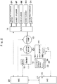
- an explanation will be made of the system configuration in the hydraulic excavator 1 with reference to Fig. 2 and Fig. 3 .
- the engine 11 is mounted on the revolving frame 5.
- the engine 11 is configured of an internal combustion engine such as a diesel engine.
- the hydraulic pump 13 and the electric motor 15 are attached mechanically to the output side of the engine 11 for serial connection.
- the hydraulic pump 13 and the electric motor 15 are driven by the engine 11.
- the engine 11 is configured of an electrically controlled engine, and an operation of the engine 11 is controlled by an engine control unit 21 (hereinafter, referred to as "ECU 12").
- ECU 12 an engine control unit 21
- a supply quantity of fuel into cylinders (combustion chambers), that is, an injection quantity of a fuel injection device (an electrically controlled injection valve) for injecting fuel into the cylinders is variably controlled by the ECU 12 as a control section of the engine 11.
- the ECU 12 includes a microcomputer, and is connected to a main controller 28 (hereinafter, referred to as "MC 28") to be described later.
- MC 28 main controller 28
- the ECU 12 variably controls a fuel injection quantity into the cylinders by the fuel injection device based upon a control signal (a command signal) from the MC 28 to control a rotational speed of the engine 11. That is, the ECU 12 controls an output torque, the rotational speed (engine rotational number) and the like of the engine 11 based upon an engine output command from the MC 28. It should be noted that the maximum output of the engine 11 is made smaller than the maximum power of the hydraulic pump 13, for example.
- the hydraulic pump 13 is connected mechanically to the engine 11.
- the hydraulic pump 13 can be driven by the torque of the engine 11 alone.
- the hydraulic pump 13 can be driven by a compound torque (a total torque) acquired by adding an assist torque of the electric motor 15 to the torque of the engine 11. That is, the hydraulic pump 13 is driven by the mechanical power of the engine 11 and the electric motor 15.
- the hydraulic pump 13 pressurizes hydraulic oil reserved in a tank (not shown), which is delivered to the traveling hydraulic motor 2A, the revolving hydraulic motor 3A, the cylinders 8D, 8E and 8F of the working mechanism 8 as pressurized oil.
- the hydraulic pump 13 is connected through the control valve 14 to the traveling hydraulic motor 2A, the revolving hydraulic motor 3A, and the cylinders 8D, 8E and 8F in the working mechanism 8 as the hydraulic devices (hydraulic actuators) .
- the hydraulic pump 13 is configured of a variable displacement hydraulic pump of a swash plate type, a bent axis type or a radial piston type, for example. In this case, although the illustration is omitted, the hydraulic pump 13 has a regulator (a variable displacement part and a tilting actuator) for regulating a pump capacity.
- the hydraulic pump 13 (the regulator thereof) is variably controlled by a command from the MC 28 to be described later.
- the control valve 14 is a control valve device formed of a plurality of directional control valves, a collector of a plurality of electromagnetic valves, and the like.
- the control valve 14 distributes hydraulic oil delivered from the hydraulic pump 13 to the hydraulic devices of the hydraulic motors 2A, 3A, the cylinders 8D, 8E, 8F and the like. That is, the control valve 14 controls a direction of the pressurized oil to be delivered to the hydraulic devices 2A, 3A, 8D, 8E, 8F from the hydraulic pump 13 in response to lever operations and pedal operations of the traveling lever/pedal operation device and the working lever operation device located in the cab 6, a command from the MC 28, and the like. Thereby, the hydraulic devices 2A, 3A, 8D, 8E, 8F are driven by the pressurized oil (the hydraulic oil) to be delivered from the hydraulic pump 13.
- the electric motor 15, also called the motor or the motor generator, is connected mechanically to the engine 11.
- the electric motor 15 is configured of, for example, a synchronous electric motor and the like.
- the electric motor 15 plays two roles of power generation of performing power supply to the electricity storage device 19 by acting as an electric generator using the engine 11 as a power source, and power running of assisting in driving the engine 11 and the hydraulic pump 13 as driven bodies by acting as a motor using power from the electricity storage device 19 as a power source. Accordingly, the assist torque of the electric motor 15 is added to the torque of the engine 11 according to the situation, and the hydraulic pump 13 is driven by these torques.
- the traveling operation and the revolving operation of the vehicle, the tilting or the lifting operation of the working mechanism 8 and the like are performed by the pressurized oil delivered from the hydraulic pump 13.
- the electric motor 15 is connected to a pair of DC buses 18A, 18B through the inverter 16. That is, the inverter 16 is provided between the electric motor 15 and the electricity storage device 19, and is connected electrically to the electric motor 15 and the electricity storage device 19.
- the inverter 16 performs conversion of power (energy conversion), and for example, is configured using a plurality of switching elements such as a transistor and an insulating gate bipolar transistor (IGBT).
- the PCU 17 includes a microcomputer, and is connected to the hybrid controller 27 to be described later (hereinafter, referred to as "HC 27") .
- the DC buses 18A, 18B are paired at a positive electrode side and at a negative electrode side, and, for example, a DC voltage of approximately several hundreds V is applied thereto.
- the inverter 16 converts AC power from the electric motor 15 into DC power, which is supplied to the electricity storage device 19.
- the inverter 16 converts the DC power of the DC buses 18A, 18B into AC power, which is supplied to the electric motor 15.
- the PCU 17 controls the on and off operation of each of the switching elements in the inverter 16 based upon a power generation electric motor output command from the HC 27, and the like. Thereby the PCU 17 controls power generation at the power generation time and drive power at the power running time of the electric motor 15.
- the electricity storage device 19 is connected electrically via the inverter 16 to the electric motor 15.
- the electricity storage device 19 is connected via the DC buses 18A, 18B to a DC side positive electrode and a DC side negative electrode of the inverter 16.
- the electricity storage device 19 supplies drive power toward the electric motor 15 at the power running time (at the assist drive time) of the electric motor 15, and is charged with power supplied from the electric motor 15 at the power generation time of the electric motor 15. That is, the electricity storage device 19 supplies the power to the electric motor 15, or is charged with generation power supplied from the electric motor 15. In other words, the electricity storage device 19 performs the supply of the energy for driving the electric motor 15 and regeneration of the energy generated by the electric motor 15.
- the electricity storage device 19 is provided with a lithium-ion secondary cell 20 corresponding to a capacitor (including a storage cell), a current sensor 21, a battery control unit 22 (hereinafter, referred to as "BCU 22"), relays 23, 24, 25 and a resistance 26, for example.
- the electricity storage device 19 is controlled by the BCU 22.
- a charging operation or a discharging operation of the lithium-ion secondary cell 20 in the electricity storage device 19 is controlled by the HC 27 based upon information from the BCU 22.
- the lithium-ion secondary cell 20 is configured of an assembled battery by electrically connecting a plurality of battery cells in series or in parallel, or in series and in parallel.
- the current sensor 21 is connected to, for example, a terminal in the positive electrode side of the lithium-ion secondary cell 20 to detect (measure) the charging current or discharging current of the electricity storage device 19 (the lithium-ion secondary cell 20).
- An output side of the current sensor 21 is connected to the BCU 22.
- the current sensor 21 outputs a signal in accordance with the detected current to the BCU 22.
- a current value detected by the current sensor 21 is inputted to the BCU 22, and in addition thereto, a voltage and a temperature of the lithium-ion secondary cell 20 are inputted thereto. Therefore, for example, the lithium-ion secondary cell 20 is provided with a voltage sensor (not shown) detecting (measuring) a voltage of the lithium-ion secondary cell 20, and a temperature sensor (not shown) detecting (measuring) a temperature of the lithium-ion secondary cell 20.
- the output side of the voltage sensor and the output side of the temperature sensor are connected to the BCU 22.
- the voltage sensor outputs a signal in accordance with the detected voltage to the BCU 22, and the temperature sensor outputs a signal in accordance with the detected temperature to the BCU 22.
- the BCU 22 as the electricity storage device controller includes a microcomputer, and is connected to the HC 27 to be described later.
- the BCU 22 controls the electricity storage device 19. That is, the BCU 22 executes predetermined calculation processing based upon a voltage and a temperature of the lithium-ion secondary cell 20, and a current value measured by the current sensor 21, thus carrying out the state determination, calculation and control of the lithium-ion secondary cell 20.
- the BCU 22 calculates possible discharging power from the electricity storage device 19 as a battery discharging power, based upon the current, the voltage and the temperature. Likewise, the BCU 22 calculates possible charging power to the electricity storage device 19 as a battery charging power.
- the BCU 22 outputs a battery state of charge (SOC), a battery discharging power, a battery charging power and the like to the HC 27.
- SOC battery state of charge
- the BCU 22 monitors and estimates a state of the electricity storage device 19 based upon the voltage, the current, the temperature, the SOC (State of Charge), a SOH (State of Health) and the like. In a case where any index of the plurality of elements deviates or is likely to deviate from an appropriate use range, the BCU 22 transmits a signal to the HC 27 to issue abnormality alarm.
- the relays 23, 24, 25 and the resistance 26 configure a contactor.
- the relays 23, 24, 25 connect or disconnect an electrical circuit (an electric equipment circuit) to which the inverter 16 and the electricity storage device 19 are connected. That is, the relays 23, 24, 25 establish the connection or disconnection between the electricity storage device 19 (a terminal of the lithium-ion secondary cell 20) and the inverter 16 (a terminal in the DC side thereof). Therefore, the relays 23, 24, 25 are provided between the inverter 16 and the electricity storage device 19. Specifically, the relays 23, 24, 25 are provided between the terminal of the lithium-ion secondary cell 20 and the terminal in the DC side of the inverter 16.
- the relays 23, 24 are provided in parallel connection between a positive side terminal of the lithium-ion secondary cell 20 and a DC side positive electrode of the inverter 16.
- the resistance 26 is provided in series with the relay 23 between the positive side terminal of the lithium-ion secondary cell 20 and the relay 23 to prevent incoming current at the relay operation.
- the relay 23 defines an incoming current preventive circuit together with the resistance 26.
- the relay 23 and the relay 24 carry out the connection or disconnection between the positive electrode of the lithium-ion secondary cell 20 and the DC side positive electrode of the inverter 16.
- the relay 25 is provided between the negative side terminal of the lithium-ion secondary cell 20 and the DC side negative electrode of the inverter 16.
- the relay 25 carries out the connection or disconnection between the negative electrode of the lithium-ion secondary cell 20 and the DC side negative electrode of the inverter 16.
- the relays 23, 24, 25 turn off (open), and the electricity storage device 19 (the lithium-ion secondary cell 20) and the inverter 16 are disconnected.
- the relays 23, 24, 25 turn on (close) in response to a command from the HC 27, for example, whereby the electricity storage device 19 (the lithium-ion secondary cell 20) and the inverter 16 are connected.
- the relays 23, 24, 25, first, the relays 23, 25 turn on, and then, the relay 24 turns on and the relay 23 turns off.
- the HC 27 as the equipment controller is configured of a microcomputer, for example.
- the HC 27 is connected electrically (to be capable of communicating) to the ECU 12, the PCU 17, the BCU 22 and the MC 28 using a CAN (Controller Area Network) and the like.
- the HC 27 is a controller in the upper position (the upper controller) of the BCU 22.
- an operation amount sensor (not shown) is connected to the MC 28 to detect an operation amount of each of the traveling lever/pedal operation device and the working lever operation device that are operated by an operator, for example.
- the MC 28 also includes a microcomputer, for example.
- the MC 28 is communicated with the ECU 12 and the HC 27, and transmits various control signals to the ECU 12, the PCU 17 and the HC 27 based upon, for example, the operation amount, the rotational speed of the engine 11, the SOC of the electricity storage device 19, and the like. Thereby, the ECU 12 controls the rotational speed of the engine 11 and the like based upon the control signal from the MC 28.
- the HC 27 controls the hybrid equipment 15, 16, 19 based upon states of the electric motor 15, the inverter 16 and the electricity storage device 19 as the hybrid equipment and information of the operation amount from the MC 28.
- the MC 28 controls the hydraulic pump 13 (a capacity thereof) and the control valve 14 (a pilot pressure thereto) based upon the information of the operation amount.
- the MC 28 controls the engine 11 and the hydraulic pump 13. In addition thereto, the MC 28 controls the control valve 14 to control the traveling hydraulic motor 2A, the revolving hydraulic motor 3A, and the cylinders 8D, 8E, 8F in the working mechanism 8, as the hydraulic devices.
- the HC 27 controls the electricity storage device 19 and the inverter 16 and performs coordination control with the MC 28.
- the HC 27 performs the coordination control with the MC 28 and controls the electric motor 15, the inverter 16 and the BCU 22.
- the relay disconnecting the electrical circuit is controlled by the single controller. Therefore, for example, in a case where the controller dealing with the control of the relay is in failure or is erroneously operated, the excitation current in the relay cannot be stopped, creating a possibility of being incapable of disconnecting the relay. This is not preferable, for example, since in the lithium-ion secondary cell 20 requiring accurate control of the voltage, the current and the temperature, the abnormal state of the overcharge, the over-discharge, the overtemperature or the like is possibly in progress.
- the first embodiment is configured to be capable of controlling the supply and the stop of the excitation current in the relay 25 with the HC 27 as the equipment controller and further, to be capable of controlling the supply and the stop of the excitation current in the relay 25 with the BCU 22 also as the electricity storage device controller. Therefore, an explanation will be made of the control of the relay 25 in the first embodiment with reference to Fig. 4 to Fig. 8 in addition to Fig. 1 to Fig. 3 .
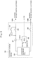
- Fig. 4 shows a relay control circuit.
- the first embodiment will be explained by taking the relay control circuit for controlling the supply and the stop of the excitation current in the relay 25 in the negative electrode side in the electricity storage device 19 (the lithium-ion secondary cell 20), as an example.
- the relay control circuit is, however, not limited thereto, but may be configured to control the supply and the stop of the excitation current in the relay 24 (and the relay 23 as needed) in the positive electrode side in the electricity storage device 19 (the lithium-ion secondary cell 20). Further, the relay control circuit may be configured to control the supply and the stop of the excitation current in the relays 25, 24 (and the relay 23 as needed) in both of the negative electrode side and the positive electrode side in the electricity storage device 19 (the lithium-ion secondary cell 20).
- a power source 29 is a power source as a supply source of the relay excitation current, and for example, can use an in-vehicle battery of 12V, 24V or the like for accessory drive, which is mounted in the hydraulic excavator 1.
- the power source 29 is connected to an excitation circuit 25A in the relay 25.
- the relay 25 is connected to the DC side negative electrode of the inverter 16 and the negative electrode of the lithium-ion secondary cell 20.
- the relay 25 is connected or disconnected by the relay excitation current from the power source 29.
- the relay 25 closes (turns on) when the relay excitation current is supplied to the excitation circuit 25A (an excitation coil) from the power source 29 (when the excitation circuit 25A is in power supply), and the negative side of the lithium-ion secondary cell 20 is connected to the DC side negative electrode of the inverter 16.
- the relay 25 opens (turns off) when the supply of the relay excitation current to the excitation circuit 25A from the power source 29 is stopped (when the excitation circuit 25A is in non-power supply), and the negative side of the lithium-ion secondary cell 20 is disconnected to the DC side negative electrode of the inverter 16.
- An excitation current control section configured to control the supply and the stop of the excitation current in the relay 25 is provided in each of the HC 27 and the BCU 22. That is, in the first embodiment, the HC 27 and the BCU 22 each have the excitation current control section configured to control the supply and the stop of the excitation current in the relay 25.
- the excitation current control section is configured of switches, specifically FET switches 30, 31 as field-effect transistor switches for switching the supply and the stop of the excitation current in the relay 25.
- the BCU 22 is provided with the first FET switch 30 as the excitation current control section
- the HC 27 is provided with the second FET switch 31 as the excitation current control section.
- the BCU 22 as the electricity storage device controller has the first FET switch 30 as the relay control section for controlling the supply and the stop of the operating current in the relay 25.
- the HC 27 as the upper controller has the second FET switch 31 as the relay control section for controlling the supply and the stop of the operating current in the relay 25.
- the first FET switch 30 installed (mounted) in the BCU 22 and the second FET switch 31 installed (mounted) in the HC 27 are connected in series. That is, the first FET switch 30 is provided in the BCU 22 with a drain terminal connected to the excitation circuit 25A in the relay 25.
- the second FET switch 31 is provided in the HC 27 with a drain terminal connected to the FET switch 31 in the BCU 22 and with a source terminal connected to a GND 32 (the vehicle body or the like) as the ground.
- a pair of diodes 33 are positioned between the first FET switch 30 and the second FET switch 31 and are provided in parallel connection in the HC 27 as a reverse flow preventive device for preventing a reverse flow of the current.
- the first FET switch 30 switches in turning on or off by the BCU 22.
- the second FET switch 31 switches in turning on or off by the HC 27.
- the relay excitation current is supplied via the power source 29 to the excitation circuit 25A, and the relay 25 turns on (closes) .
- the relay excitation current to the excitation circuit 25A is stopped, and the relay 25 turns off (opens).
- the first FET switch 30 and the second FET switch 31 each are provided in the controllers (the BCU 22 and the HC 27), but may be provided outside of the controllers.
- the FET switch and the controller each configured to control the FET switch may comprise two or more ones.
- a controller in addition to the BCU 22 and the HC 27, that is, a third FET switch may be provided in the MC 28 (in serial connection to the first FET switch 30 and the second FET switch 31).
- the PCU 17 as the controller of the inverter 16 may be provided with the third FET switch.
- the third FET switch may be provided in a controller (not shown) specialized in control at the abnormal time of the relay disconnection, for example.
- the first FET switch 30 and the second FET switch 31 both are located between the excitation circuit 25A in the relay 25 and the GND 32, but, for example, may be located between the power source 29 and the excitation circuit 25A in the relay 25.
- any of the first FET switch 30 and the second FET switch 31 may be located between the power source 29 and the excitation circuit 25A in the relay 25, and the other may be located between the excitation circuit 25A in the relay 25 and the GND 32.
- the field-effect transistor switch is used as the switch, but for example, another switching device such as a bipolar transistor or the like may be used.
- the two FET switches 30, 31 each are provided in the BCU 22 and the HC 27, and the two FET switches 30, 31 are in series connected.
- the BCU 22 determines that a state of the electricity storage device 19 (the lithium-ion secondary cell 20) is an abnormal state of requiring the stop of the excitation current in the relay 25, the BCU 22 transmits an abnormal signal to the HC 27. That is, the BCU 22 has an electricity storage device abnormal state notifying section 34 configured to notify (inform) the HC 27 of the abnormal state of the electricity storage device 19.
- the BCU 22 when a predetermined time T has elapsed after transmitting the abnormal signal, turns off (opens) the first FET switch 30 of the BCU 22 regardless of the state of the relay 25. That is, whether the second FET switch 31 in the HC 27 turns off (opens) or turns on (closes), the excitation current in the relay 25 is stopped by turning off (opens) the first FET switch 30 in the BCU 22.
- the predetermined time T can be in advance set as a time required for the HC 27 to make the current of the inverter 16, finally the current of the electric motor 15 be zero. That is, the predetermined time T can be in advance set as a time slightly longer than a time required for the HC 27 to null output of the inverter 16 (a time required for turning off a gate of IGBT and nulling inverter output), such as approximately several hundred milliseconds to one second.
- the HC 27 turns off (opens) the second FET switch 31 in the HC 27 after executing the stop processing based upon the abnormal signal from the BCU 22, and thereby stops the excitation current in the relay 25 and transmits a signal of the state of the relay 25 (for example, the effect that the relay 25 opens) to the other controller (for example, the MC 28, the BCU 22 or the like).
- the stop processing of the HC 27 is processing of cutting off the current in the electrical equipment circuit (the electric equipment circuit) to zero.
- the stop processing of the HC 27 is the processing of outputting a stop command to the PCU 17, nulling the output of the inverter 16 and cutting off the current of the electric motor 15 to zero.
- the control by the BCU 22 and the HC 27, that is, the control processing of the HC 27 shown in Fig. 5 and the control processing of the BCU 22 shown in Fig. 6 will be in detail explained later.
- the hydraulic excavator 1 according to the first embodiment has the configuration as described above, and next, an operation thereof will be explained.
- the hydraulic pump 13 and the electric motor 15 are driven by the engine 11.
- the hydraulic oil delivered by the hydraulic pump 13 is delivered to the traveling hydraulic motor 2A, the revolving hydraulic motor 3A, and the boom cylinder 8D, the arm cylinder 8E and the bucket cylinder 8F in the working mechanism 8 in response to the lever operation and the pedal operation of the traveling lever/pedal operation device and the working lever operation device provided in the cab 6.
- the hydraulic excavator 1 can perform the traveling operation by the lower traveling structure 2, the revolving operation of the upper revolving structure 4, the excavating operation of the working mechanism 8, and the like.
- the electric motor 15 when the output torque of the engine 11 is larger than the drive torque of the hydraulic pump 13 at the operating of the hydraulic excavator 1, the electric motor 15 is driven as a power generator by the extra torque. Thereby, the electric motor 15 generates AC power, and the AC power is converted into DC power by the inverter 16, which is stored in the electricity storage device 19. Meanwhile, when the output torque of the engine 11 is smaller than the drive torque of the hydraulic pump 13, the electric motor 15 is driven as an electric motor by the power from electricity storage device 19, which assists in a drive of the engine 11.
- the first FET switch 30 of the BCU 22 and the second FET switch 31 of the HC 27 both turn on (close), creating a state where the excitation current is supplied to the excitation circuit 25A in the relay 25, that is, the relay 25 is in the connection state.
- Fig. 5 shows the control processing of the HC 27.
- Fig. 6 shows the control processing of the BCU 22.
- the ignition key switch turns on and the activation processing in the hydraulic excavator 1 is executed.
- the HC 27 executes regular control processing in S1.
- the HC 27 executes regular control of the electric equipment. That is, the HC 27 executes control (predetermine control) when the inverter 16 as the electric equipment and the electricity storage device 19 are normal.
- the HC 27 executes processing of S2 to S4 as well.
- the processing of S2 to S4 is processing for observation and determination on whether an operation of various equipment is normal or abnormal.
- the HC 27 monitors all of the equipment (electric equipment) in an electric system including the electricity storage device 19.
- soft abnormality is mainly detected. That is, in S2 it is determined whether or not the monitored items of the HC 27 are normal. For example, it is determined whether or not a calculation value of the HC 27 is within an allowable range (a control range). In other words, it is determined whether or not the control of the HC 27 itself is within a normal range.
- S3 it is determined whether or not a state of the electric equipment, that is, states of the electricity storage device 19 and the inverter 16 are normal. That is, in S3, the HC 27 determines whether or not the reports from the BCU 22 and the inverter 16 are normal. For example, the HC 27 determines whether or not a physical numerical value (a detection value) of the electricity storage device 19 obtained from the BCU 22 in the electricity storage device 19 and a physical numerical value (a detection value) of the inverter 16 obtained from the PCU 17 in the inverter 16 each are within an allowable range (a normal range and a control range). In S4, it is determined whether or not a communication connection state is normal. That is, the HC 27 determines whether or not the communication connection state between the BCU 22, the PCU 17 and the MC 28 is normal.
- a state of the electric equipment that is, states of the electricity storage device 19 and the inverter 16 are normal. That is, in S3, the HC 27 determines whether or not the reports from the BCU 22 and the
- the HC 27 cuts off the current flowing in the electric equipment circuit to zero.
- the HC 27 outputs a command of setting the output of the inverter 16 to an off state to the PCU 17 to cut off the current of the electric motor 15 to zero.
- the relay is disconnected in S7. That is, the HC 27 turns off (opens) the second FET switch 31 in the HC 27 to disconnect the relay 25.
- the electric equipment stops, and then, the HC 27 becomes in the stop state.
- the relay When the current flowing in the electric equipment circuit is cut off to zero in S12, the relay is disconnected in S13. That is, in S13, as similar to the processing in S7, the HC 27 turns off (opens) the second FET switch 31 in the HC 27 to disconnect the relay 25.
- the relay state is transmitted in subsequent S14. That is, in S14 the HC 27 transmits the effect that the relay 25 is disconnected, to the BCU 22, for example.
- S16 subsequent to S15 it is determined whether or not the ignition key switch is in the off state. In a case where in S16 "NO” is made, that is, the ignition key switch is determined to be in the on state, the process goes back to S15, and the processing subsequent to S15 is repeated. Meanwhile, in a case where "YES” is made in determination in S16, that is, the ignition key switch is determined to be in the off state, the HC 27 stops.
- the ignition key switch becomes in the on state and the activation processing in the hydraulic excavator 1 is executed.
- the BCU 22 executes regular control processing in S21.
- the BCU 22 executes regular control of the electricity storage device 19. That is, the BCU 22 executes the control (predetermined control) when the electricity storage device 19 is normal.
- the BCU 22 executes processing of S22 to S24 as well.
- the processing of S22 to S24 is processing for observation and determination on whether the electricity storage device 19 is normal or abnormal.
- the BCU 22 monitors information in regard to the electricity storage device 19.
- S22 it is determined whether or not the monitored items of the BCU 22 are normal. For example, it is determined whether or not each of a voltage, a current, a temperature, an SOC and a SOH of the lithium-ion secondary cell 20 is within an allowable range (a normal range) .
- S23 it is determined whether or not a report from the HC 27 is normal. That is, the BCU 22 and the HC 27 notify abnormality to each other.
- S23 it is determined whether or not the BCU 22 receives a normal signal from the HC 27 (in other words, whether to receive an abnormal signal).
- S24 it is determined whether or not the communication connection state is normal. That is, the BCU 22 determines whether or not the communication connection state to the HC 27 is normal.
- termination processing of the BCU 22 is executed.
- the BCU 22 executes termination processing of storage (memory) of data in the lithium-ion secondary cell 20, or the like.
- the relay disconnection is made in S27. That is, in S27, the BCU 22 turns off (opens) the first FET switch 30 in the BCU 22 to disconnect the relay 25.
- the BCU 22 becomes in the stop state.
- the process goes to S31.
- abnormality alarm is issued.
- the BCU 22 transmits a signal (an abnormal signal) of the effect that the abnormality is present, to the HC 27 (the electricity storage device abnormal state notifying section 34).
- timer processing is executed. That is, in S32, the BCU 22 determines whether or not a predetermined time T has elapsed after it is determined that the BCU 22 is not normal (abnormal) (in other words, after the abnormality alarm is issued) .
- the predetermined time T can be set as a time required for the HC 27 to cut off the current of the electric motor 15 to zero.
- the process goes to S33, wherein the relay disconnection is performed. That is, in S33, the BCU 22 disconnects the relay 25 by turning off (opening) the first FET switch 30 of the BCU 22.
- Fig. 7 shows regular abnormal processing in time series in a case where the HC 27 disconnects the relay 25 .
- the electricity storage device 19 the lithium-ion secondary cell 20
- the BCU 22 transitions to the abnormal state to issue the abnormality as communication information.
- the timer processing starts at the same time. That is, when "NO" is determined in S22 in Fig. 6 , the BCU 22 issues abnormality alarm in S31 and starts the timer processing in S32.
- the HC 27 transitions to the abnormal state by the communication information (abnormality alarm issue) of the BCU 22, and executes the stop processing of the electric equipment control, and cuts off the current of the electric equipment circuit to zero. After that, the second FET switch 31 mounted in the HC 27 is made to turn off to disconnect the relay 25. That is, when "NO" is determined in S3 in Fig. 5 , the HC 27 executes the stop processing in S12 to cut off the current of the electric equipment circuit to zero. After that, the second FET switch 31 mounted on the HC 27 is caused to turn off by the processing in S13 to disconnect the relay 25.
- the BCU 22 turns off the first FET switch 30 mounted on the BCU 22. That is, when the timer processing in S32 in Fig. 6 is completed (terminated), the BCU 22 turns off the first FET switch 30 in S33. In this case, since the relay 25 is already disconnected by the second FET switch 31 mounted in the HC 27, the state of the relay 25 has no change.
- the timer processing (S32 in Fig. 6 ) is executed from the abnormal state of the BCU 22 to the relay disconnection in the regular abnormal processing. Accordingly, by stopping the electric equipment control in the meanwhile (in the middle of timer processing) by the HC 27, the relay 25 can be disconnected after setting the current of the electrical equipment circuit to zero. Therefore, it is possible to suppress relay damages due to a back electromotive force or arc discharge at the time of disconnecting the relay 25.
- Fig. 8 shows abnormal processing in an emergency in time series in a case where the BCU 22 disconnects the relay 25.
- the electricity storage device 19 the lithium-ion secondary cell 20
- the BCU 22 transitions to the abnormal state to issue the abnormality alarm as communication information.
- the timer processing starts at the same time. That is, when "NO" is determined in S22 in Fig. 6 , the BCU 22 issues the abnormality alarm in S31 and starts the timer processing in S32.
- the BCU 22 in which the timer processing is completed turns off the first FET switch 30 mounted on the BCU 22 to disconnect the relay 25.
- the BCU 22 performs the relay disconnection regardless of the presence or absence of the current in the electric equipment circuit to stop the operation of the electric equipment. Accordingly, it is possible to suppress the lithium-ion secondary cell 20 in the electricity storage device 19 from being in progress in the abnormal state such as overcharging, over-discharging, or overtemperature. As a result, it is possible to improve the safety.
- the HC 27 as the equipment controller and the BCU 22 as the electricity storage device controller each include the first FET switch 30 and the second FET switch 31 that are the switches as the excitation current control section. That is, the supply and the stop of the excitation current of the relay 25 can be controlled by the second FET switch 31 of the HC 27 and also by the first FET switch 30 of the BCU 22. Therefore, even when one controller of the HC 27 and the BCU 22 is in failure or is erroneously operated, it is possible to disconnect the relay 25 by stopping the excitation current in the relay 25 with the switch (the first FET switch 30 or the second FET switch 31) of the other controller.
- the excitation current in the relay 25 is stopped by the first FET switch 30 of the BCU 22 regardless of the state of the relay 25. Therefore, when the predetermined time T has elapsed after the BCU 22 determines that the electricity storage device 19 is in the abnormal state, the excitation current in the relay 25 can be stopped by the first FET switch 30 in the BCU 22 regardless of the failure or the erroneous operation of the HC 27.
- the field-effect transistors of N channels are used as the first FET switch 30 and the second FET switch 31.
- the illustration is omitted, it is preferable to provide the configuration of the following (1) to (4) in a circuit in Fig. 4 .
- the HC 27 executes the stop processing based upon the abnormal signal from the BCU 22, and thereafter, stops the excitation current in the relay 25 by the second FET switch 31 of the HC 27. That is, the HC 27 executes the stop processing, and thereafter, stops the excitation current in the relay 25. Therefore, by the stop processing of the HC 27 the current of the electrical equipment circuit is made to zero, and after that, the excitation current in the relay 25 is stopped, thus making it possible to disconnect the relay 25. Thereby, it is possible to suppress the relay damage due to the back electromotive force or the arc discharge at the relay disconnection. Further, the HC 27 transmits a signal of the relay state. Therefore, it is possible to notify the other controller (for example, the BCU 22) that the relay 25 is disconnected by the second FET switch 31 of the HC 27.
- the other controller for example, the BCU 22
- the relay 25 the connection and the disconnection of which are controlled by both of the HC 27 and the BCU 22 is provided between the electricity storage device 19 (the lithium-ion secondary cell 20 thereof) and the inverter 16. That is, the relay 25 is provided in the electrical circuit including the electricity storage device 19 (the lithium-ion secondary cell 20 thereof) as the power source and the inverter 16, and the relay 25 disconnects the electricity storage device 19 and the inverter 16. Therefore, the relay 25 can stop the power supply to the inverter 16 by disconnecting the electricity storage device 19 and the inverter 16.
- the hydraulic excavator 1 is composed of the hybrid construction machine provided with the engine 11 connected mechanically to the electric motor 15. That is, the hydraulic pump 13 is driven by the engine 11 and the electric motor 15.
- the electricity storage device 19 supplies the power to the electric motor 15, and is charged with the generated power by the electric motor 15.
- the MC 28 controls the engine 11, the hydraulic pump 13, and the control valve 14 (via the control valve 14 the MC 28 controls the traveling hydraulic motor 2A, the revolving hydraulic motor 3A, and the cylinders 8D, 8E, 8F of the working mechanism 8 as the hydraulic devices). Therefore, it is possible to improve the safety of the mount equipment and the vehicle body in the hybrid hydraulic excavator 1.
- Fig. 9 shows a second embodiment.
- the second embodiment is characterized in that an excitation current control section in an equipment controller and an excitation current control section in an electricity storage device controller change switches through an AND circuit.
- components identical to those in the first embodiment are referred to as identical reference numerals, and the explanation is omitted.
- a single FET switch 41 is provided between the excitation circuit 25A in the relay 25 and the GND 32.
- the FET switch 41 has a drain terminal connected to the excitation circuit 25A in the relay 25 and a source terminal connected to the GND 32.
- the FET switch 41 is a switch for switching the supply and the stop of the excitation current in the relay 25.
- An HC 42 and a BCU 43 are connected via an AND circuit 44 to the FET switch 41.
- the HC 42 controls the electric motor 15, the inverter 16, and the BCU 43.
- the BCU 43 also controls the electricity storage device 19.
- an excitation current control section 42A in the HC 42 outputs 1 (high) to the AND circuit 44 when the relay 25 is caused to turn on (close), that is, when the electricity storage device 19 (the lithium-ion secondary cell 20) and the inverter 16 are connected.
- the relay 25 is caused to turn off (open) by the processing in S7 or in S13 in Fig. 5 , that is, when the electricity storage device 19 (the lithium-ion secondary cell 20) and the inverter 16 are disconnected
- the excitation current control section 42A in the HC 42 outputs 0 (low) to the AND circuit 44.
- an excitation current control section 43A in the BCU 43 outputs 1 (high) to the AND circuit 44 when the relay 25 is caused to turn on (close), that is, when the electricity storage device 19 (the lithium-ion secondary cell 20) and the inverter 16 are connected.
- the relay 25 is caused to turn off (open) by the processing in S27 or in S33 in Fig. 6 , that is, when the electricity storage device 19 (the lithium-ion secondary cell 20) and the inverter 16 are disconnected, 0 (low) is outputted to the AND circuit 44.
- the HC 42 and the BCU 43 each have the excitation current control sections 42A, 43A configured to control the supply and the stop of the excitation current in the relay 25.
- the excitation current control section 42A in the HC 42 is configured as a command output section that outputs a command signal for turning on or off (closing or opening) the relay 25 to the FET switch 41 via the AND circuit 44.
- the excitation current control section 43A in the BCU 43 also is configured as a command output section that outputs a command signal for turning on or off (closing or opening) the relay 25 to the FET switch 41 via the AND circuit 44.
- the second embodiment is configured to switch the FET switch 41 via the AND circuit 44 by the excitation current control section 42A in the HC 42 and the excitation current control section 43A in the BCU 43 as described above, and does not differ particularly in the basic function from the first embodiment as described before.
- the supply and the stop of the excitation current in the relay 25 can be controlled by the excitation current control section (the command output section) 42A in the HC 42 and also by the excitation current control section (the command output section) 43A in the BCU 43. Therefore, even when one controller of the HC 42 and the BCU 43 is in failure or is erroneously operated, it is possible to disconnect the relay 25 by stopping the excitation current in the relay 25 with the excitation current control section (the command output section) 42A or 43A of the other controller. Accordingly, it is possible to improve the certainty of the stop of the excitation current in the relay 25, that is, the certainty of the disconnection of the relay 25.
- the FET switch 41 and the AND circuit 44 are provided to be separate from the HC 42 and the BCU 43. However, not limited thereto, the FET switch 41 and the AND circuit 44 may be provided within the HC 42 or the BCU 43, for example.
- Fig. 10 shows a third embodiment.
- the third embodiment is characterized in that a hydraulic excavator as a construction machine is an electric hydraulic excavator. It should be noted that in the third embodiment, components identical to those in the first embodiment are referred to as identical reference numerals, and the explanation is omitted.
- the electric motor 15 drives the hydraulic pump 13 as a driven body.
- the electricity storage device 19, as similar to the first embodiment, supplies power via the inverter 16 to the electric motor 15.
- the electricity storage device 19 is electrically connected via the relay 25 to the inverter 16.
- the inverter 16 converts the power supplied from the electricity storage device 19 to be supplied to the electric motor 15.
- the relay 25 is provided between the electricity storage device 19 and the inverter 16 to electrically connect or disconnect the electricity storage device 19 and the inverter 16.
- the MC 28 controls the hydraulic pump 13. In addition thereto, the MC 28 controls the control valve 14 to control the traveling hydraulic motor 2A, the revolving hydraulic motor 3A, and the cylinders 8D, 8E, 8F of the working mechanism 8 as the hydraulic devices.
- An electric equipment controller 51 (hereinafter, referred to as "EC 51") as the equipment controller performs coordination control with the MC 28 and controls the electric motor 15, the inverter 16 and the BCU 22.
- the EC 51 as similar to the equipment controller (the HC 27) in the first embodiment, responds to the upper controller provided with the relay control section (the second FET switch 31) for controlling the supply and the stop of the operating current in the relay 25.
- the upper controller (the EC 51 in Fig. 10 , and the HC 27 in Fig. 2 as described before) communicates with the BCU 22.
- the BCU 22 is the controller of the electricity storage device 19, that is, the electricity storage device controller that manages the state of the electricity storage device 19.
- the BCU 22 and the upper controller each have the relay control sections (the first FET switch 30 and the second FET switch 31) for controlling the supply and the stop of the operating current in the relay 25. That is, the BCU 22 includes the electricity storage device abnormal state notifying section 34 configured to, when the electricity storage device 19 becomes in the abnormal state of electrically disconnecting the electricity storage device 19 and the inverter 16 by the relay 25, notify the upper controller (the EC 51) of the abnormal state of the electricity storage device 19.
- the BCU 22 includes the relay control section (the first FET switch 30) configured to, when the electricity storage device 19 becomes in the abnormal state, stop the supply of the operating current in the relay 25 regardless of the supply of the operating current of the relay 25 is stopped by the upper controller (the EC 51) notifying the abnormal state of the electricity storage device 19.
- the relay control section (the first FET switch 30) configured to, when the electricity storage device 19 becomes in the abnormal state, stop the supply of the operating current in the relay 25 regardless of the supply of the operating current of the relay 25 is stopped by the upper controller (the EC 51) notifying the abnormal state of the electricity storage device 19.
- the predetermined time T is set to be longer than a time from a point where the abnormal state of the electricity storage device 19 is notified until a point where the current flowing between the electricity storage device 19 and the electric motor 15 becomes zero by the disconnection of the relay 25, or a time until a point where the supply of the operating current in the relay 25 is stopped by the relay control section (the second FET switch 31) of the upper controller (the EC 51).
- the EC 51 and the BCU 22 each have the excitation current control sections (the first FET switch 30 and the second FET switch 31) configured to control the supply and the stop of the excitation current in the relay 25. That is, in the third embodiment, the EC 51 has the second FET switch 31 as the excitation current control as similar to the HC 27 in the first embodiment.
- the third embodiment is configured to control the supply and the stop of the excitation current in the relay 25 with the second FET switch 31 of the EC 51 and the first FET switch 30 of the BCU 22 as described above, and does not differ particularly in the basic function from the first embodiment as described above. That is, the third embodiment also, as similar to the first embodiment, even when one controller of the EC 51 and the BCU 22 is in failure or is erroneously operated, can disconnect the relay 25 by stopping the excitation current in the relay 25 with the switches (the first FET switch 30 and the second FET switch 31) of the other controller.
- the first embodiment is explained by taking a case where the relay 25 provided between the negative side terminal of the lithium-ion secondary cell 20 and the DC side negative electrode of the inverter 16 can be disconnected by both of the HC 27 and the BCU 22, as an example.
- the relay 24 (and the relay 23 as needed) provided between the positive side terminal of the lithium-ion secondary cell 20 and the DC side positive electrode of the inverter 16 may be disconnected by both of the HC 27 and the BCU 22.
- the relays 25, 24 (and the relay 23 as needed) may be disconnected by both of the HC 27 and the BCU 22. This configuration can be likewise applied to the second embodiment and the third embodiment.
- the first embodiment is explained by taking a case of using the lithium-ion secondary cell 20 in the electricity storage device 19, as an example, but another secondary cell (for example, a nickel cadmium battery or nickel hydrogen battery) or a capacitor that can supply necessary power may be used.
- a step-up and-down device such as a DC-DC converter may be provided between an electricity storage device and a DC bus. This configuration can be likewise applied to the second embodiment and the third embodiment.
- the first embodiment is explained by taking the hybrid hydraulic excavator 1 of a crawler type as a construction machine, as an example.
- the present invention can be applied to various kinds of hybrid construction machines such as a wheel type hybrid hydraulic excavator, a hybrid wheel loader, and a hybrid dump truck, which are provided with an electric motor connected to an engine and a hydraulic pump, and an electricity storage device.
- This configuration can be likewise applied to the second embodiment.
- the third embodiment is explained by taking the electric hydraulic excavator of a crawler type as a construction machine, as an example.
- the present inventio is not limited thereto, but the present invention can be applied to various kinds of electric construction machines driving a hydraulic pump by an electric motor alone, such as a wheel type electric hydraulic excavator, an electric wheel loader, and an electric dump truck.
- the first to third embodiments are explained by taking a case where the present invention is applied to the electric system to be mounted on the construction machine, but an example of the electric system to which the present invention is applied may include an electric system used for vehicle drive or accessory drive in automobiles such as hybrid cars or electric cars, an electric system to be mounted on industrial vehicles such as forklifts, or an electric system to be mounted on railroad vehicles such as hybrid trains.
- the configurations of the electric system are the same as the configurations shown in Fig. 2 or Fig. 10 . That is, a mechanical connection destination of the electric motor changes depending upon the electric system, but the configuration of each of the electric motor, the inverter, the electricity storage device and the equipment controller (the HC) explained in the first to third embodiments can be basically applied as it is.
Landscapes
- Engineering & Computer Science (AREA)
- Mechanical Engineering (AREA)
- Transportation (AREA)
- Combustion & Propulsion (AREA)
- Chemical & Material Sciences (AREA)
- Power Engineering (AREA)
- Sustainable Energy (AREA)
- Life Sciences & Earth Sciences (AREA)
- Sustainable Development (AREA)
- General Engineering & Computer Science (AREA)
- Civil Engineering (AREA)
- Structural Engineering (AREA)
- Mining & Mineral Resources (AREA)
- Health & Medical Sciences (AREA)
- Biomedical Technology (AREA)
- General Health & Medical Sciences (AREA)
- Automation & Control Theory (AREA)
- Electric Propulsion And Braking For Vehicles (AREA)
- Operation Control Of Excavators (AREA)
- Hybrid Electric Vehicles (AREA)
- Protection Of Static Devices (AREA)
- Charge And Discharge Circuits For Batteries Or The Like (AREA)
Abstract
Description
- The present invention relates to an electricity storage device controller, an electric system provided with the electricity storage device controller and a construction machine on which the electric system is mounted.
- As the background art in regard to the technical field, there are techniques disclosed in
Patent Document 1 andPatent Document 2.Patent Document 1 discloses the technique on disconnection of a relay at the vehicle stop request in a motor/generator and a high voltage circuit of an electric vehicle.Patent Document 2 discloses the technique on disconnection of a relay at the system main relay disconnection request due to a hybrid system failure. -
- Patent Document 1:
- Japanese Patent Laid-Open No.
2010-193558 A 5233725 B - Patent Document 2:
- Japanese Patent Laid-Open No.
2006-217743 A - Recently, as measures of environment destruction prevention, the tightening of emission regulations of gases emitted due to combustion of fuel or low fuel consumption of a system with an internal combustion engine as a power source has been in progress by developed countries as leaders. As one of the measures, the approach of motorizing the power source mounted on the system has been made. The motorization of the power source can be achieved by using an electricity storage device storing power as the power source and driving an electric motor mechanically connected to a driven body with the power supplied from the electricity storage device. The electricity storage device is provided with a plurality of capacitors electrically connected in series, in parallel, or in series and in parallel. In many cases a secondary cell such as a lithium-ion cell, a lead cell or a nickel-hydrogen cell is used in the capacitor. Recently, among the secondary cells, adoption of the lithium-ion cell high in output of energy and in volumetric density in capacity has spread as the mainstream.
- For continuing to safely use of the electricity storage device over a long period of time, the capacitor is required to be not used over the use range. That is, it is required to control charge/discharge of the capacitor in such a manner that a voltage, a charge/discharge current, a temperature, a charging state, a degradation state and the like of the capacitor are monitored to prevent the capacitor from leading to an abnormal state such as overcharge, over-discharge or an overtemperature. Therefore, the electricity storage device is provided with a controller configured to manage the aforementioned monitoring and control. In a case where the capacitor becomes in the abnormal state such as overcharge, over-discharge or an overtemperature, it is necessary to disconnect an electrical circuit between the electricity storage device and the electric motor and electrically disconnect the electricity storage device from the electric motor side. Therefore, a relay is provided in the electrical circuit between the electricity storage device and the electric motor, as described in
Patent Document 1 for example. The relay can input or disconnect a contact point by controlling an operating current (an excitation current flowing in an excitation coil), as described inPatent Document 2. - In the background art, however, the operating current of the relay is controlled by a single control system. Therefore, in a case where the control system controlling the operating current in the relay is in failure or erroneously operated, the relay is not normally operated and the electricity storage device is not disconnected electrically from the electric motor side, possibly leading the capacitor to the abnormal state such as overcharge, over-discharge or an overtemperature.
- In view of the above-mentioned, one of the problems to be solved by the present invention is to improve certainty on the circuit disconnection by the relay.
- One of the problems can be solved in such a manner that a relay control section configured to control supply and stop of an operating current in a relay is provided in each of at least two controllers and the supply or stop of the operating current in the relay can be achieved by the relay control section in each of the controllers. In this case, it is preferable that the supply or the stop of the operating current in the relay by the relay control section in one of the controllers can be achieved without any relation to the supply or stop of the operating current in the relay by the relay control section in the other of the controllers. In addition, it is preferable that the supply or the stop of the operating current in the relay by the relay control section by the one of the controllers is achieved after a predetermined time has elapsed from a point when the supply or stop of the operating current in the relay is required, for example, a time until the current flowing between the electricity storage device and the electric motor becomes in a zero state by the disconnection of the relay or a time until the supply of the operating current in the relay by the relay control section in the other of the controllers is stopped has elapsed.
- Here, according to one aspect of the present invention, a construction machine includes: an electric motor; a hydraulic pump driven by the electric motor; a hydraulic device driven by pressurized oil delivered from the hydraulic pump; an electricity storage device that supplies power to the electric motor; an inverter provided between the electricity storage device and the electric motor to convert the power; a main controller that controls the hydraulic pump and the hydraulic device; an electricity storage device controller that controls the electricity storage device; an equipment controller that controls the electric motor, the inverter and the electricity storage device controller; and a relay connecting or disconnecting an electrical circuit to which the inverter and the electricity storage device are connected, characterized in that: the equipment controller and the electricity storage device controller each include an excitation current control section that controls supply and stop of an excitation current in the relay.
- According to another aspect of the present invention, an electric system includes: an electric motor driving a driven body; an electricity storage device that supplies power to the electric motor; an inverter provided between the electric motor and the electricity storage device to convert the power supplied from the electricity storage device and supply the converted power to the electric motor; a relay provided between the electricity storage device and the inverter to electrically connect or disconnect the electricity storage device and the inverter; an electricity storage device controller that manages a state of the electricity storage device; an upper controller that communicates with the electricity storage device controller, characterized in that: the electricity storage device controller and the upper controller each include a relay control section that controls supply and stop of an operating current in the relay.
- Further, according to a further other aspect of the present invention, an electricity storage device controller in an electricity storage device that is connected electrically via a relay to an inverter and supplies power via the inverter to an electric motor driving a driven body, includes: an electricity storage device abnormal state notifying section configured to, when the electricity storage device becomes in an abnormal state of electrically disconnecting the electricity storage device and the inverter by the relay, notify an upper controller provided with a relay control section that controls supply and stop of an operating current in the relay of the abnormal state of the electricity storage device; and a relay control section configured to, when the electricity storage device becomes in the abnormal state of electrically disconnecting the electricity storage device and the inverter by the relay, stop the supply of the operating current in the relay with no relation to whether or not the supply of the operating current in the relay is stopped by the upper controller notifying the abnormal state of the electricity storage device.
- According to the present invention, it is possible to improve certainty of the circuit disconnection by the relay.
- That is, an explanation will be made of a construction machine as one aspect of the present invention, as an example, the equipment controller and the electricity storage device controller each include the excitation current control section (the relay control section) . That is, the supply and the stop of the excitation current in the relay can be controlled by the excitation current control section in the equipment controller and also by the excitation current control section in the electricity storage device controller. Therefore, even when one controller of the equipment controller and the electricity storage device controller is in failure or is erroneously operated, it is possible to disconnect the relay by stopping the excitation current in the relay with the excitation current control section of the other controller. Accordingly, it is possible to improve the certainty of the stop of the excitation current in the relay, that is, the certainty of the disconnection of the relay. As a result, it is possible to improve the safety of the mounted equipment and the vehicle body in the construction machine.
-
-
Fig. 1 is a front view showing a hybrid hydraulic excavator according to a first embodiment of the present invention. -
Fig. 2 is a block diagram showing a hydraulic system and an electric system that are applied to the hybrid hydraulic excavator inFig. 1 . -
Fig. 3 is a block diagram showing an electricity storage device inFig. 2 . -
Fig. 4 is a circuit diagram showing a relay, a BCU and an HC. -
Fig. 5 is a flow chart showing control processing of the HC. -
Fig. 6 is a flow chart showing control processing of the BCU. -
Fig. 7 is a characteristic line diagram showing an example of a time change of electric equipment, the HC, the BCU, the relay and the like in a case where the HC disconnects the relay. -
Fig. 8 is a characteristic line diagram showing an example of a time change of the electric equipment, the HC, the BCU, the relay and the like in a case where the BCU disconnects the relay. -
Fig. 9 is a circuit diagram showing a relay, a BCU and an HC according to a second embodiment. -
Fig. 10 is a block diagram showing an electric hydraulic excavator according to a third embodiment, as similar toFig. 2 . - Hereinafter, a hybrid hydraulic excavator as an example of a construction machine according to an embodiment in the present invention will be explained with reference to the accompanying drawings.
- It should be noted that embodiments to be hereinafter described will be explained by taking a hybrid hydraulic excavator on which a lithium-ion cell is mounted, as an example, but the present invention is not limited thereto. For example, the present invention can be applied to various kinds of hybrid construction machines such as a hybrid wheel loader or a hybrid dump truck, using power of a hydraulic pump driven by an electric motor connected to an electricity storage device and an engine as a power source. In addition, the present invention can be applied to various kinds of electric construction machines using an electricity storage device as a power source, further, various kinds of industrial machines composed of the similar equipment structure.
-
Fig. 1 to Fig. 8 show a first embodiment of the present invention. A hybrid hydraulic excavator 1 (hereinafter, referred to as "hydraulic excavator 1") is provided with anengine 11 and anelectric motor 15, which will be described later. Thehydraulic excavator 1 includes an automotivelower traveling structure 2 of a crawler type, a revolvingdevice 3 that is provided on thelower traveling structure 2, an upper revolvingstructure 4 that is mounted through the revolvingdevice 3 on thelower traveling structure 2 to be capable of revolving thereon, and aworking mechanism 8 of an articulated structure that is provided in the front side of the upper revolvingstructure 4 and performs an excavating operation of earth and sand, and the like. At this time, thelower traveling structure 2 and the upper revolvingstructure 4 configure a vehicle body of thehydraulic excavator 1. - The
upper revolving structure 4 includes a revolvingframe 5 as a support structure (a base frame) of theupper revolving structure 4, acab 6, acounterweight 7, theengine 11, ahydraulic pump 13, theelectric motor 15, aninverter 16, anelectricity storage device 19 and the like, which are mounted on the revolvingframe 5. - The
cab 6 defining an operation room is provided in the front left side of the revolvingframe 5. An operator's seat on which an operator sits is provided in thecab 6. Operation devices for operating thehydraulic excavator 1, that is, a traveling lever/pedal operation device, a working lever operation device (none of them is shown) and the like are provided on the periphery of the operator's seat. - The operation device outputs a pilot signal (a pilot pressure) in response to a lever operation or a pedal operation by an operator to a
control valve 14 to be described later (see,Fig. 2 ). As a result, the operator can operate (drive) hydraulic devices (hydraulic actuators) in thehydraulic excavator 1, that is, a travelinghydraulic motor 2A, abucket cylinder 8F, anarm cylinder 8E, aboom cylinder 8D, a revolvinghydraulic motor 3A (see,Fig. 2 ) and the like - An ignition key switch (not shown) is provided in the
cab 6 for performing on and off operations of the power source (on and off operations of accessories) in thehydraulic excavator 1 and start or stop of theengine 11. Further, ahybrid controller 27 and amain controller 28 to be described later (see,Fig. 2 ) are provided in thecab 6 to be located in the lower side backward of the operator's seat. Meanwhile, thecounterweight 7 is located in the rear end side of the revolvingframe 5 to act as a weight balance to the workingmechanism 8. - As shown in
Fig. 1 , the workingmechanism 8 is configured of, for example, a boom 8A, anarm 8B and abucket 8C as a working tool, and aboom cylinder 8D, anarm cylinder 8E and abucket cylinder 8F as a working tool cylinder, which drive which drive the boom 8A, thearm 8B and the bucket. The boom 8A, thearm 8B and thebucket 8C are joined to each other by pin. - The working mechanism 8 (the boom 8A thereof) is attached to the revolving
frame 5 in the upper revolvingstructure 4. The workingmechanism 8 extends or contracts thecylinders hydraulic excavator 1 travels with rotation of the travelinghydraulic motor 2A (see,Fig. 2 ) provided on thelower traveling structure 2. The upper revolvingstructure 4 revolves with rotation of the revolvinghydraulic motor 3A (see,Fig. 2 ) configuring the revolvingdevice 3 together with a revolving bearing (not shown). - Here, the
hydraulic excavator 1 is provided thereon with an electric system that controls theelectric motor 15 and the like, and a hydraulic system that controls operations of the workingmechanism 8 and the like. Hereinafter, an explanation will be made of the system configuration in thehydraulic excavator 1 with reference toFig. 2 andFig. 3 . - The
engine 11 is mounted on the revolvingframe 5. Theengine 11 is configured of an internal combustion engine such as a diesel engine. As shown inFig. 2 , thehydraulic pump 13 and theelectric motor 15 are attached mechanically to the output side of theengine 11 for serial connection. Thehydraulic pump 13 and theelectric motor 15 are driven by theengine 11. - Here, the
engine 11 is configured of an electrically controlled engine, and an operation of theengine 11 is controlled by an engine control unit 21 (hereinafter, referred to as "ECU 12"). Specifically, in theengine 11, a supply quantity of fuel into cylinders (combustion chambers), that is, an injection quantity of a fuel injection device (an electrically controlled injection valve) for injecting fuel into the cylinders is variably controlled by theECU 12 as a control section of theengine 11. In this case, theECU 12 includes a microcomputer, and is connected to a main controller 28 (hereinafter, referred to as "MC 28") to be described later. - The
ECU 12 variably controls a fuel injection quantity into the cylinders by the fuel injection device based upon a control signal (a command signal) from theMC 28 to control a rotational speed of theengine 11. That is, theECU 12 controls an output torque, the rotational speed (engine rotational number) and the like of theengine 11 based upon an engine output command from theMC 28. It should be noted that the maximum output of theengine 11 is made smaller than the maximum power of thehydraulic pump 13, for example. - The
hydraulic pump 13 is connected mechanically to theengine 11. Thehydraulic pump 13 can be driven by the torque of theengine 11 alone. In addition, thehydraulic pump 13 can be driven by a compound torque (a total torque) acquired by adding an assist torque of theelectric motor 15 to the torque of theengine 11. That is, thehydraulic pump 13 is driven by the mechanical power of theengine 11 and theelectric motor 15. Thehydraulic pump 13 pressurizes hydraulic oil reserved in a tank (not shown), which is delivered to the travelinghydraulic motor 2A, the revolvinghydraulic motor 3A, thecylinders mechanism 8 as pressurized oil. - The
hydraulic pump 13 is connected through thecontrol valve 14 to the travelinghydraulic motor 2A, the revolvinghydraulic motor 3A, and thecylinders mechanism 8 as the hydraulic devices (hydraulic actuators) . Thehydraulic pump 13 is configured of a variable displacement hydraulic pump of a swash plate type, a bent axis type or a radial piston type, for example. In this case, although the illustration is omitted, thehydraulic pump 13 has a regulator (a variable displacement part and a tilting actuator) for regulating a pump capacity. The hydraulic pump 13 (the regulator thereof) is variably controlled by a command from theMC 28 to be described later. - The
control valve 14 is a control valve device formed of a plurality of directional control valves, a collector of a plurality of electromagnetic valves, and the like. Thecontrol valve 14 distributes hydraulic oil delivered from thehydraulic pump 13 to the hydraulic devices of thehydraulic motors cylinders control valve 14 controls a direction of the pressurized oil to be delivered to thehydraulic devices hydraulic pump 13 in response to lever operations and pedal operations of the traveling lever/pedal operation device and the working lever operation device located in thecab 6, a command from theMC 28, and the like. Thereby, thehydraulic devices hydraulic pump 13. - The
electric motor 15, also called the motor or the motor generator, is connected mechanically to theengine 11. Theelectric motor 15 is configured of, for example, a synchronous electric motor and the like. Theelectric motor 15 plays two roles of power generation of performing power supply to theelectricity storage device 19 by acting as an electric generator using theengine 11 as a power source, and power running of assisting in driving theengine 11 and thehydraulic pump 13 as driven bodies by acting as a motor using power from theelectricity storage device 19 as a power source. Accordingly, the assist torque of theelectric motor 15 is added to the torque of theengine 11 according to the situation, and thehydraulic pump 13 is driven by these torques. The traveling operation and the revolving operation of the vehicle, the tilting or the lifting operation of the workingmechanism 8 and the like are performed by the pressurized oil delivered from thehydraulic pump 13. - As shown in
Fig.2 , theelectric motor 15 is connected to a pair ofDC buses inverter 16. That is, theinverter 16 is provided between theelectric motor 15 and theelectricity storage device 19, and is connected electrically to theelectric motor 15 and theelectricity storage device 19. Theinverter 16 performs conversion of power (energy conversion), and for example, is configured using a plurality of switching elements such as a transistor and an insulating gate bipolar transistor (IGBT). - On and off operation of each of the switching elements in the
inverter 16 are controlled by a power control unit 17 (hereinafter, referred to as "PCU 17"). ThePCU 17 includes a microcomputer, and is connected to thehybrid controller 27 to be described later (hereinafter, referred to as "HC 27") . TheDC buses - At the power generation of the
electric motor 15, theinverter 16 converts AC power from theelectric motor 15 into DC power, which is supplied to theelectricity storage device 19. At the power running operation of theelectric motor 15, theinverter 16 converts the DC power of theDC buses electric motor 15. ThePCU 17 controls the on and off operation of each of the switching elements in theinverter 16 based upon a power generation electric motor output command from theHC 27, and the like. Thereby thePCU 17 controls power generation at the power generation time and drive power at the power running time of theelectric motor 15. - The
electricity storage device 19 is connected electrically via theinverter 16 to theelectric motor 15. In this case, theelectricity storage device 19 is connected via theDC buses inverter 16. Theelectricity storage device 19 supplies drive power toward theelectric motor 15 at the power running time (at the assist drive time) of theelectric motor 15, and is charged with power supplied from theelectric motor 15 at the power generation time of theelectric motor 15. That is, theelectricity storage device 19 supplies the power to theelectric motor 15, or is charged with generation power supplied from theelectric motor 15. In other words, theelectricity storage device 19 performs the supply of the energy for driving theelectric motor 15 and regeneration of the energy generated by theelectric motor 15. - As shown in
Fig. 3 , theelectricity storage device 19 is provided with a lithium-ionsecondary cell 20 corresponding to a capacitor (including a storage cell), acurrent sensor 21, a battery control unit 22 (hereinafter, referred to as "BCU 22"), relays 23, 24, 25 and aresistance 26, for example. Theelectricity storage device 19 is controlled by theBCU 22. Specifically, a charging operation or a discharging operation of the lithium-ionsecondary cell 20 in theelectricity storage device 19 is controlled by theHC 27 based upon information from theBCU 22. - Here, the lithium-ion
secondary cell 20 is configured of an assembled battery by electrically connecting a plurality of battery cells in series or in parallel, or in series and in parallel. Thecurrent sensor 21 is connected to, for example, a terminal in the positive electrode side of the lithium-ionsecondary cell 20 to detect (measure) the charging current or discharging current of the electricity storage device 19 (the lithium-ion secondary cell 20). An output side of thecurrent sensor 21 is connected to theBCU 22. Thecurrent sensor 21 outputs a signal in accordance with the detected current to theBCU 22. - A current value detected by the
current sensor 21 is inputted to theBCU 22, and in addition thereto, a voltage and a temperature of the lithium-ionsecondary cell 20 are inputted thereto. Therefore, for example, the lithium-ionsecondary cell 20 is provided with a voltage sensor (not shown) detecting (measuring) a voltage of the lithium-ionsecondary cell 20, and a temperature sensor (not shown) detecting (measuring) a temperature of the lithium-ionsecondary cell 20. The output side of the voltage sensor and the output side of the temperature sensor are connected to theBCU 22. The voltage sensor outputs a signal in accordance with the detected voltage to theBCU 22, and the temperature sensor outputs a signal in accordance with the detected temperature to theBCU 22. - The
BCU 22 as the electricity storage device controller includes a microcomputer, and is connected to theHC 27 to be described later. TheBCU 22 controls theelectricity storage device 19. That is, theBCU 22 executes predetermined calculation processing based upon a voltage and a temperature of the lithium-ionsecondary cell 20, and a current value measured by thecurrent sensor 21, thus carrying out the state determination, calculation and control of the lithium-ionsecondary cell 20. - For example, the
BCU 22 calculates possible discharging power from theelectricity storage device 19 as a battery discharging power, based upon the current, the voltage and the temperature. Likewise, theBCU 22 calculates possible charging power to theelectricity storage device 19 as a battery charging power. TheBCU 22 outputs a battery state of charge (SOC), a battery discharging power, a battery charging power and the like to theHC 27. - In addition thereto, the
BCU 22 monitors and estimates a state of theelectricity storage device 19 based upon the voltage, the current, the temperature, the SOC (State of Charge), a SOH (State of Health) and the like. In a case where any index of the plurality of elements deviates or is likely to deviate from an appropriate use range, theBCU 22 transmits a signal to theHC 27 to issue abnormality alarm. - The
relays resistance 26 configure a contactor. Therelays inverter 16 and theelectricity storage device 19 are connected. That is, therelays relays inverter 16 and theelectricity storage device 19. Specifically, therelays secondary cell 20 and the terminal in the DC side of theinverter 16. - In this case, the
relays secondary cell 20 and a DC side positive electrode of theinverter 16. Theresistance 26 is provided in series with therelay 23 between the positive side terminal of the lithium-ionsecondary cell 20 and therelay 23 to prevent incoming current at the relay operation. Thereby therelay 23 defines an incoming current preventive circuit together with theresistance 26. Therelay 23 and therelay 24 carry out the connection or disconnection between the positive electrode of the lithium-ionsecondary cell 20 and the DC side positive electrode of theinverter 16. Meanwhile, therelay 25 is provided between the negative side terminal of the lithium-ionsecondary cell 20 and the DC side negative electrode of theinverter 16. Therelay 25 carries out the connection or disconnection between the negative electrode of the lithium-ionsecondary cell 20 and the DC side negative electrode of theinverter 16. - For example, when an unillustrated ignition key switch turns off, the
relays inverter 16 are disconnected. Meanwhile, when the ignition key switch turns on by an operator, therelays HC 27, for example, whereby the electricity storage device 19 (the lithium-ion secondary cell 20) and theinverter 16 are connected. At this time, in regard to therelays relays relay 24 turns on and therelay 23 turns off. - The
HC 27 as the equipment controller is configured of a microcomputer, for example. TheHC 27 is connected electrically (to be capable of communicating) to theECU 12, thePCU 17, theBCU 22 and theMC 28 using a CAN (Controller Area Network) and the like. TheHC 27 is a controller in the upper position (the upper controller) of theBCU 22. Meanwhile, an operation amount sensor (not shown) is connected to theMC 28 to detect an operation amount of each of the traveling lever/pedal operation device and the working lever operation device that are operated by an operator, for example. TheMC 28 also includes a microcomputer, for example. - The
MC 28 is communicated with theECU 12 and theHC 27, and transmits various control signals to theECU 12, thePCU 17 and theHC 27 based upon, for example, the operation amount, the rotational speed of theengine 11, the SOC of theelectricity storage device 19, and the like. Thereby, theECU 12 controls the rotational speed of theengine 11 and the like based upon the control signal from theMC 28. TheHC 27 controls thehybrid equipment electric motor 15, theinverter 16 and theelectricity storage device 19 as the hybrid equipment and information of the operation amount from theMC 28. TheMC 28 controls the hydraulic pump 13 (a capacity thereof) and the control valve 14 (a pilot pressure thereto) based upon the information of the operation amount. - That is, the
MC 28 controls theengine 11 and thehydraulic pump 13. In addition thereto, theMC 28 controls thecontrol valve 14 to control the travelinghydraulic motor 2A, the revolvinghydraulic motor 3A, and thecylinders mechanism 8, as the hydraulic devices. TheHC 27 controls theelectricity storage device 19 and theinverter 16 and performs coordination control with theMC 28. TheHC 27 performs the coordination control with theMC 28 and controls theelectric motor 15, theinverter 16 and theBCU 22. - Incidentally according to the conventional technology as described before, the relay disconnecting the electrical circuit is controlled by the single controller. Therefore, for example, in a case where the controller dealing with the control of the relay is in failure or is erroneously operated, the excitation current in the relay cannot be stopped, creating a possibility of being incapable of disconnecting the relay. This is not preferable, for example, since in the lithium-ion
secondary cell 20 requiring accurate control of the voltage, the current and the temperature, the abnormal state of the overcharge, the over-discharge, the overtemperature or the like is possibly in progress. - On the other hand, the first embodiment is configured to be capable of controlling the supply and the stop of the excitation current in the
relay 25 with theHC 27 as the equipment controller and further, to be capable of controlling the supply and the stop of the excitation current in therelay 25 with theBCU 22 also as the electricity storage device controller. Therefore, an explanation will be made of the control of therelay 25 in the first embodiment with reference toFig. 4 to Fig. 8 in addition toFig. 1 to Fig. 3 . -
Fig. 4 shows a relay control circuit. The first embodiment will be explained by taking the relay control circuit for controlling the supply and the stop of the excitation current in therelay 25 in the negative electrode side in the electricity storage device 19 (the lithium-ion secondary cell 20), as an example. The relay control circuit is, however, not limited thereto, but may be configured to control the supply and the stop of the excitation current in the relay 24 (and therelay 23 as needed) in the positive electrode side in the electricity storage device 19 (the lithium-ion secondary cell 20). Further, the relay control circuit may be configured to control the supply and the stop of the excitation current in therelays 25, 24 (and therelay 23 as needed) in both of the negative electrode side and the positive electrode side in the electricity storage device 19 (the lithium-ion secondary cell 20). - In
Fig. 4 , apower source 29 is a power source as a supply source of the relay excitation current, and for example, can use an in-vehicle battery of 12V, 24V or the like for accessory drive, which is mounted in thehydraulic excavator 1. Thepower source 29 is connected to anexcitation circuit 25A in therelay 25. Therelay 25 is connected to the DC side negative electrode of theinverter 16 and the negative electrode of the lithium-ionsecondary cell 20. Therelay 25 is connected or disconnected by the relay excitation current from thepower source 29. - That is, the
relay 25 closes (turns on) when the relay excitation current is supplied to theexcitation circuit 25A (an excitation coil) from the power source 29 (when theexcitation circuit 25A is in power supply), and the negative side of the lithium-ionsecondary cell 20 is connected to the DC side negative electrode of theinverter 16. On the other hand, therelay 25 opens (turns off) when the supply of the relay excitation current to theexcitation circuit 25A from thepower source 29 is stopped (when theexcitation circuit 25A is in non-power supply), and the negative side of the lithium-ionsecondary cell 20 is disconnected to the DC side negative electrode of theinverter 16. - An excitation current control section configured to control the supply and the stop of the excitation current in the
relay 25 is provided in each of theHC 27 and theBCU 22. That is, in the first embodiment, theHC 27 and theBCU 22 each have the excitation current control section configured to control the supply and the stop of the excitation current in therelay 25. The excitation current control section is configured of switches, specifically FET switches 30, 31 as field-effect transistor switches for switching the supply and the stop of the excitation current in therelay 25. TheBCU 22 is provided with thefirst FET switch 30 as the excitation current control section, and theHC 27 is provided with thesecond FET switch 31 as the excitation current control section. That is, theBCU 22 as the electricity storage device controller has thefirst FET switch 30 as the relay control section for controlling the supply and the stop of the operating current in therelay 25. TheHC 27 as the upper controller has thesecond FET switch 31 as the relay control section for controlling the supply and the stop of the operating current in therelay 25. - The
first FET switch 30 installed (mounted) in theBCU 22 and thesecond FET switch 31 installed (mounted) in theHC 27 are connected in series. That is, thefirst FET switch 30 is provided in theBCU 22 with a drain terminal connected to theexcitation circuit 25A in therelay 25. Thesecond FET switch 31 is provided in theHC 27 with a drain terminal connected to theFET switch 31 in theBCU 22 and with a source terminal connected to a GND 32 (the vehicle body or the like) as the ground. A pair ofdiodes 33 are positioned between thefirst FET switch 30 and thesecond FET switch 31 and are provided in parallel connection in theHC 27 as a reverse flow preventive device for preventing a reverse flow of the current. - The
first FET switch 30 switches in turning on or off by theBCU 22. Thesecond FET switch 31 switches in turning on or off by theHC 27. When thefirst FET switch 30 and thesecond FET switch 31 both turn on (close), the relay excitation current is supplied via thepower source 29 to theexcitation circuit 25A, and therelay 25 turns on (closes) . Meanwhile, when at least one of thefirst FET switch 30 and thesecond FET switch 31 turns off (opens), the relay excitation current to theexcitation circuit 25A is stopped, and therelay 25 turns off (opens). - The
first FET switch 30 and thesecond FET switch 31 each are provided in the controllers (theBCU 22 and the HC 27), but may be provided outside of the controllers. The FET switch and the controller each configured to control the FET switch may comprise two or more ones. For example, a controller in addition to theBCU 22 and theHC 27, that is, a third FET switch may be provided in the MC 28 (in serial connection to thefirst FET switch 30 and the second FET switch 31). In addition, thePCU 17 as the controller of theinverter 16 may be provided with the third FET switch. Further, the third FET switch may be provided in a controller (not shown) specialized in control at the abnormal time of the relay disconnection, for example. - In the first embodiment, the
first FET switch 30 and thesecond FET switch 31 both are located between theexcitation circuit 25A in therelay 25 and theGND 32, but, for example, may be located between thepower source 29 and theexcitation circuit 25A in therelay 25. In addition, any of thefirst FET switch 30 and thesecond FET switch 31 may be located between thepower source 29 and theexcitation circuit 25A in therelay 25, and the other may be located between theexcitation circuit 25A in therelay 25 and theGND 32. Further, in the first embodiment, the field-effect transistor switch is used as the switch, but for example, another switching device such as a bipolar transistor or the like may be used. - In any case, in the first embodiment, the two FET switches 30, 31 each are provided in the
BCU 22 and theHC 27, and the two FET switches 30, 31 are in series connected. In a case where theBCU 22 determines that a state of the electricity storage device 19 (the lithium-ion secondary cell 20) is an abnormal state of requiring the stop of the excitation current in therelay 25, theBCU 22 transmits an abnormal signal to theHC 27. That is, theBCU 22 has an electricity storage device abnormalstate notifying section 34 configured to notify (inform) theHC 27 of the abnormal state of theelectricity storage device 19. In addition thereto, theBCU 22, when a predetermined time T has elapsed after transmitting the abnormal signal, turns off (opens) thefirst FET switch 30 of theBCU 22 regardless of the state of therelay 25. That is, whether thesecond FET switch 31 in theHC 27 turns off (opens) or turns on (closes), the excitation current in therelay 25 is stopped by turning off (opens) thefirst FET switch 30 in theBCU 22. - In this case, the predetermined time T can be in advance set as a time required for the
HC 27 to make the current of theinverter 16, finally the current of theelectric motor 15 be zero. That is, the predetermined time T can be in advance set as a time slightly longer than a time required for theHC 27 to null output of the inverter 16 (a time required for turning off a gate of IGBT and nulling inverter output), such as approximately several hundred milliseconds to one second. - On the other hand, the
HC 27 turns off (opens) thesecond FET switch 31 in theHC 27 after executing the stop processing based upon the abnormal signal from theBCU 22, and thereby stops the excitation current in therelay 25 and transmits a signal of the state of the relay 25 (for example, the effect that therelay 25 opens) to the other controller (for example, theMC 28, theBCU 22 or the like). In this case, the stop processing of theHC 27 is processing of cutting off the current in the electrical equipment circuit (the electric equipment circuit) to zero. For example, the stop processing of theHC 27 is the processing of outputting a stop command to thePCU 17, nulling the output of theinverter 16 and cutting off the current of theelectric motor 15 to zero. The control by theBCU 22 and theHC 27, that is, the control processing of theHC 27 shown inFig. 5 and the control processing of theBCU 22 shown inFig. 6 will be in detail explained later. - The
hydraulic excavator 1 according to the first embodiment has the configuration as described above, and next, an operation thereof will be explained. - When an operator who has got in the
cab 6 activates theengine 11, thehydraulic pump 13 and theelectric motor 15 are driven by theengine 11. Thereby, the hydraulic oil delivered by thehydraulic pump 13 is delivered to the travelinghydraulic motor 2A, the revolvinghydraulic motor 3A, and theboom cylinder 8D, thearm cylinder 8E and thebucket cylinder 8F in the workingmechanism 8 in response to the lever operation and the pedal operation of the traveling lever/pedal operation device and the working lever operation device provided in thecab 6. Thereby, thehydraulic excavator 1 can perform the traveling operation by thelower traveling structure 2, the revolving operation of the upper revolvingstructure 4, the excavating operation of the workingmechanism 8, and the like. - Here, when the output torque of the
engine 11 is larger than the drive torque of thehydraulic pump 13 at the operating of thehydraulic excavator 1, theelectric motor 15 is driven as a power generator by the extra torque. Thereby, theelectric motor 15 generates AC power, and the AC power is converted into DC power by theinverter 16, which is stored in theelectricity storage device 19. Meanwhile, when the output torque of theengine 11 is smaller than the drive torque of thehydraulic pump 13, theelectric motor 15 is driven as an electric motor by the power fromelectricity storage device 19, which assists in a drive of theengine 11. At this time, thefirst FET switch 30 of theBCU 22 and thesecond FET switch 31 of theHC 27 both turn on (close), creating a state where the excitation current is supplied to theexcitation circuit 25A in therelay 25, that is, therelay 25 is in the connection state. - Next, an explanation will be made of the control processing of the
relay 25 by theHC 27 and theBCU 22 with reference toFig. 5 andFig. 6 . Here,Fig. 5 shows the control processing of theHC 27.Fig. 6 shows the control processing of theBCU 22. Each step in the flow charts shown inFig. 5 andFig. 6 uses notation of "S" (for example,step 1 = "Sl") . - First, an explanation will be made of the control processing of the
HC 27 as shown inFig.5 . The ignition key switch turns on and the activation processing in thehydraulic excavator 1 is executed. Thereby, when the control processing inFig. 5 is started, theHC 27 executes regular control processing in S1. In the regular control processing, theHC 27 executes regular control of the electric equipment. That is, theHC 27 executes control (predetermine control) when theinverter 16 as the electric equipment and theelectricity storage device 19 are normal. Along with it, theHC 27 executes processing of S2 to S4 as well. The processing of S2 to S4 is processing for observation and determination on whether an operation of various equipment is normal or abnormal. - That is, the
HC 27 monitors all of the equipment (electric equipment) in an electric system including theelectricity storage device 19. In addition, in S2, soft abnormality is mainly detected. That is, in S2 it is determined whether or not the monitored items of theHC 27 are normal. For example, it is determined whether or not a calculation value of theHC 27 is within an allowable range (a control range). In other words, it is determined whether or not the control of theHC 27 itself is within a normal range. - In S3, it is determined whether or not a state of the electric equipment, that is, states of the
electricity storage device 19 and theinverter 16 are normal. That is, in S3, theHC 27 determines whether or not the reports from theBCU 22 and theinverter 16 are normal. For example, theHC 27 determines whether or not a physical numerical value (a detection value) of theelectricity storage device 19 obtained from theBCU 22 in theelectricity storage device 19 and a physical numerical value (a detection value) of theinverter 16 obtained from thePCU 17 in theinverter 16 each are within an allowable range (a normal range and a control range). In S4, it is determined whether or not a communication connection state is normal. That is, theHC 27 determines whether or not the communication connection state between theBCU 22, thePCU 17 and theMC 28 is normal. - In a case where "YES" is made in determination in S2 to S4, that is, each state is determined to be normal in the determination on whether to be normal, the process goes to S5. In S5, it is determined whether or not the ignition key switch is in an off state. In a case where in S5 "NO" is made, that is, in a case where it is determined that the ignition key switch is in an on state, the process goes back to S1, and the processing subsequent to S1 is repeated. Meanwhile, in a case where "YES" is made in determination in S5, that is, in a case where it is determined that the ignition key switch in the normal state (in a case where no abnormal determination is made) is in the off state, the process goes to S6.
- In S6, electric equipment control stop processing is executed. That is, the
HC 27 cuts off the current flowing in the electric equipment circuit to zero. For example, theHC 27 outputs a command of setting the output of theinverter 16 to an off state to thePCU 17 to cut off the current of theelectric motor 15 to zero. When the current flowing in the electric equipment circuit is cut off to zero in S6, the relay is disconnected in S7. That is, theHC 27 turns off (opens) thesecond FET switch 31 in theHC 27 to disconnect therelay 25. Thereby, in S8, the electric equipment stops, and then, theHC 27 becomes in the stop state. - On the other hand, in a case where "NO" is made in determination in S2 to S4, that is, each state is determined to be not normal (abnormal) in the determination on whether to be normal, the process goes to S11. In S11, abnormality alarm is issued. For example, the
HC 27 transmits a signal (an abnormal signal) that the abnormality occurs, to theBCU 22, thePCU 17 and theMC 28. In subsequent S12, the electric equipment control stop processing is executed. That is, theHC 27, as similar to the processing in S6, cuts off the current flowing in the electric equipment circuit to zero. For example, theHC 27 outputs a command of setting the output of theinverter 16 to the off state to thePCU 17 to cut off the current of theelectric motor 15 to zero. - When the current flowing in the electric equipment circuit is cut off to zero in S12, the relay is disconnected in S13. That is, in S13, as similar to the processing in S7, the
HC 27 turns off (opens) thesecond FET switch 31 in theHC 27 to disconnect therelay 25. When therelay 25 is disconnected in S13, the relay state is transmitted in subsequent S14. That is, in S14 theHC 27 transmits the effect that therelay 25 is disconnected, to theBCU 22, for example. - When the
relay 25 is disconnected in S13, the electric equipment stops in S15 subsequent to S14. In this state, the electric equipment is stopped, but the hydraulic equipment control becomes in the continuing hydraulic mode. In this hydraulic mode, a vehicle body operation by the hydraulic power is made possible. That is, thehydraulic pump 13 is operating by theengine 11 alone, and thehydraulic excavator 1 is operable by the hydraulic oil to be delivered from thehydraulic pump 13. - In S16 subsequent to S15, it is determined whether or not the ignition key switch is in the off state. In a case where in S16 "NO" is made, that is, the ignition key switch is determined to be in the on state, the process goes back to S15, and the processing subsequent to S15 is repeated. Meanwhile, in a case where "YES" is made in determination in S16, that is, the ignition key switch is determined to be in the off state, the
HC 27 stops. - Next, an explanation will be made of the control processing of the
BCU 22 as shown inFig. 6 . The ignition key switch becomes in the on state and the activation processing in thehydraulic excavator 1 is executed. Thereby, when the control processing inFig. 6 is started, theBCU 22 executes regular control processing in S21. In the regular control processing, theBCU 22 executes regular control of theelectricity storage device 19. That is, theBCU 22 executes the control (predetermined control) when theelectricity storage device 19 is normal. Along with it, theBCU 22 executes processing of S22 to S24 as well. The processing of S22 to S24 is processing for observation and determination on whether theelectricity storage device 19 is normal or abnormal. - That is, the
BCU 22 monitors information in regard to theelectricity storage device 19. In this case, in S22 it is determined whether or not the monitored items of theBCU 22 are normal. For example, it is determined whether or not each of a voltage, a current, a temperature, an SOC and a SOH of the lithium-ionsecondary cell 20 is within an allowable range (a normal range) . In S23, it is determined whether or not a report from theHC 27 is normal. That is, theBCU 22 and theHC 27 notify abnormality to each other. In S23, it is determined whether or not theBCU 22 receives a normal signal from the HC 27 (in other words, whether to receive an abnormal signal). In S24, it is determined whether or not the communication connection state is normal. That is, theBCU 22 determines whether or not the communication connection state to theHC 27 is normal. - In a case where "YES" is made in determination in S22 to S24, that is, each state is determined to be normal in the determination on whether to be normal, the process goes to S25. In S25, it is determined whether or not the ignition key switch is in an off state. In a case where in S25 "NO" is made, that is, the ignition key switch is determined to be in an on state, the process goes back to S21, and the processing subsequent to S21 is repeated. Meanwhile, in a case where "YES" is made in determination in S25, that is, in a case where it is determined that the ignition key switch in the normal state (in a case where no abnormal determination is made) is in the off state, the process goes to S26.
- In S26, termination processing of the
BCU 22 is executed. For example, in S26, theBCU 22 executes termination processing of storage (memory) of data in the lithium-ionsecondary cell 20, or the like. When the termination processing of theBCU 22 is executed in S26, the relay disconnection is made in S27. That is, in S27, theBCU 22 turns off (opens) thefirst FET switch 30 in theBCU 22 to disconnect therelay 25. When therelay 25 is disconnected in S27, theBCU 22 becomes in the stop state. - On the other hand, in a case where "NO" is made in determination in S22 to S24, that is, each state is determined to be not normal (abnormal) in the determination on whether to be normal, the process goes to S31. In S31, abnormality alarm is issued. For example, the
BCU 22 transmits a signal (an abnormal signal) of the effect that the abnormality is present, to the HC 27 (the electricity storage device abnormal state notifying section 34). In subsequent S32, timer processing is executed. That is, in S32, theBCU 22 determines whether or not a predetermined time T has elapsed after it is determined that theBCU 22 is not normal (abnormal) (in other words, after the abnormality alarm is issued) . In this case, the predetermined time T can be set as a time required for theHC 27 to cut off the current of theelectric motor 15 to zero. - When the process waits for the predetermined time T in S32 (when the predetermined time T has elapsed), the process goes to S33, wherein the relay disconnection is performed. That is, in S33, the
BCU 22 disconnects therelay 25 by turning off (opening) thefirst FET switch 30 of theBCU 22. - In S34 subsequent to S33, it is determined whether or not the ignition key switch is in the off state. In a case where in S34 "NO" is made, that is, the ignition key switch is determined to be in the on state, the process goes back before S34, and the processing subsequent to S34 is repeated. Meanwhile, in a case where "YES" is made in determination in S34, that is, the ignition key switch is determined to be in the off state, the process goes to S35, wherein the terminal processing of the
BCU 22 is executed. For example, in S36, theBCU 22 executes the terminal processing of the storage (the memory) of the data in the lithium-ionsecondary cell 20, and the like. In S36, when the terminal processing of theBCU 22 is executed, theBCU 22 becomes in the stop state. -
Fig. 7 shows regular abnormal processing in time series in a case where theHC 27 disconnects therelay 25 . For example, in the electric equipment state, when the electricity storage device 19 (the lithium-ion secondary cell 20) rises in temperature to be in an overtemperature abnormal state (an electricity storage cell overtemperature abnormal state), theBCU 22 transitions to the abnormal state to issue the abnormality as communication information. At this time, the timer processing starts at the same time. That is, when "NO" is determined in S22 inFig. 6 , theBCU 22 issues abnormality alarm in S31 and starts the timer processing in S32. - Meanwhile, the
HC 27 transitions to the abnormal state by the communication information (abnormality alarm issue) of theBCU 22, and executes the stop processing of the electric equipment control, and cuts off the current of the electric equipment circuit to zero. After that, thesecond FET switch 31 mounted in theHC 27 is made to turn off to disconnect therelay 25. That is, when "NO" is determined in S3 inFig. 5 , theHC 27 executes the stop processing in S12 to cut off the current of the electric equipment circuit to zero. After that, thesecond FET switch 31 mounted on theHC 27 is caused to turn off by the processing in S13 to disconnect therelay 25. - When the timer processing is completed after the
relay 25 is disconnected by theHC 27, theBCU 22 turns off thefirst FET switch 30 mounted on theBCU 22. That is, when the timer processing in S32 inFig. 6 is completed (terminated), theBCU 22 turns off thefirst FET switch 30 in S33. In this case, since therelay 25 is already disconnected by thesecond FET switch 31 mounted in theHC 27, the state of therelay 25 has no change. - In this way, the timer processing (S32 in
Fig. 6 ) is executed from the abnormal state of theBCU 22 to the relay disconnection in the regular abnormal processing. Accordingly, by stopping the electric equipment control in the meanwhile (in the middle of timer processing) by theHC 27, therelay 25 can be disconnected after setting the current of the electrical equipment circuit to zero. Therefore, it is possible to suppress relay damages due to a back electromotive force or arc discharge at the time of disconnecting therelay 25. - Meanwhile,
Fig. 8 shows abnormal processing in an emergency in time series in a case where theBCU 22 disconnects therelay 25. For example, in the electric equipment state, when the electricity storage device 19 (the lithium-ion secondary cell 20) rises in temperature to be in an overtemperature abnormal state (an electricity storage cell overtemperature abnormal state), theBCU 22 transitions to the abnormal state to issue the abnormality alarm as communication information. At this time, the timer processing starts at the same time. That is, when "NO" is determined in S22 inFig. 6 , theBCU 22 issues the abnormality alarm in S31 and starts the timer processing in S32. - At this time, in a case where the
HC 27 cannot turn off thesecond FET switch 31 mounted on theHC 27 due to a failure, an erroneous operation or the like, for example, theBCU 22 in which the timer processing is completed turns off thefirst FET switch 30 mounted on theBCU 22 to disconnect therelay 25. In this way, in an emergency in which the regular relay disconnection cannot be performed by theHC 27, theBCU 22 performs the relay disconnection regardless of the presence or absence of the current in the electric equipment circuit to stop the operation of the electric equipment. Accordingly, it is possible to suppress the lithium-ionsecondary cell 20 in theelectricity storage device 19 from being in progress in the abnormal state such as overcharging, over-discharging, or overtemperature. As a result, it is possible to improve the safety. - In this way, in the first embodiment, the
HC 27 as the equipment controller and theBCU 22 as the electricity storage device controller each include thefirst FET switch 30 and thesecond FET switch 31 that are the switches as the excitation current control section. That is, the supply and the stop of the excitation current of therelay 25 can be controlled by thesecond FET switch 31 of theHC 27 and also by thefirst FET switch 30 of theBCU 22. Therefore, even when one controller of theHC 27 and theBCU 22 is in failure or is erroneously operated, it is possible to disconnect therelay 25 by stopping the excitation current in therelay 25 with the switch (thefirst FET switch 30 or the second FET switch 31) of the other controller. Accordingly, it is possible to improve the certainty of the stop of the excitation current in therelay 25, that is, the certainty of the disconnection of therelay 25. As a result, it is possible to improve the safety of the mounted equipment (for example, theelectricity storage device 19, theelectric motor 15, and the inverter 16) and the vehicle body in thehydraulic excavator 1 as the construction machine. - In the first embodiment, in a case where the
BCU 22 determines that theelectricity storage device 19 is in the abnormal state, when the predetermined time T has elapsed, the excitation current in therelay 25 is stopped by thefirst FET switch 30 of theBCU 22 regardless of the state of therelay 25. Therefore, when the predetermined time T has elapsed after theBCU 22 determines that theelectricity storage device 19 is in the abnormal state, the excitation current in therelay 25 can be stopped by thefirst FET switch 30 in theBCU 22 regardless of the failure or the erroneous operation of theHC 27. That is, even when theHC 27 cannot stop the excitation current in therelay 25 by thesecond FET switch 31 due to the failure or the erroneous operation of theHC 27, it is possible to stop the excitation current in therelay 25 by thefirst FET switch 30 in theBCU 22 when the predetermined time T has elapsed. Thereby, it is possible to improve the certainty of the stop of the excitation current in therelay 25. Even when thesecond FET switch 31 is in failure or is erroneously operated, it is possible to stop the excitation current in therelay 25 by thefirst FET switch 30 in theBCU 22. - In the first embodiment, the field-effect transistors of N channels are used as the
first FET switch 30 and thesecond FET switch 31. In this case, although the illustration is omitted, it is preferable to provide the configuration of the following (1) to (4) in a circuit inFig. 4 . - (1) It is preferable that a reverse flow preventive diode is electrically connected in series between the drain terminal of the
first FET switch 30 and theexcitation circuit 25A such that a direction from theexcitation circuit 25A toward the drain terminal of thefirst FET switch 30 is the forward direction. The reverse flow preventive diode is to prevent the reverse flow of the excitation current. - (2) It is preferable that a recirculation diode is electrically connected in series between the reverse connection preventive diode side of the
excitation circuit 25A and the power source 29-side of theexcitation circuit 25A such that a direction from the reverse connection preventive diode side of theexcitation circuit 25A toward the power source 29-side of theexcitation circuit 25A is the forward direction, to form a recirculation path. The recirculation path is to cause the excitation current flowing in theexcitation circuit 25A to be recirculated when thefirst FET switch 30 turns off. - (3) It is preferable that a protection diode at the ground offset time is electrically connected in series between the source terminal of the
first FET switch 30 and theGND 32 such that a direction from the GND 32-side toward the source terminal side of thefirst FET switch 30 is the forward direction. - (4) It is preferable that a pulldown resistance is electrically connected in series between the gate terminal and the source terminal of the
first FET switch 30 to prevent an unintended application of a gate-to-source voltage. - In the first embodiment, the
HC 27 executes the stop processing based upon the abnormal signal from theBCU 22, and thereafter, stops the excitation current in therelay 25 by thesecond FET switch 31 of theHC 27. That is, theHC 27 executes the stop processing, and thereafter, stops the excitation current in therelay 25. Therefore, by the stop processing of theHC 27 the current of the electrical equipment circuit is made to zero, and after that, the excitation current in therelay 25 is stopped, thus making it possible to disconnect therelay 25. Thereby, it is possible to suppress the relay damage due to the back electromotive force or the arc discharge at the relay disconnection. Further, theHC 27 transmits a signal of the relay state. Therefore, it is possible to notify the other controller (for example, the BCU 22) that therelay 25 is disconnected by thesecond FET switch 31 of theHC 27. - In the first embodiment, the
relay 25 the connection and the disconnection of which are controlled by both of theHC 27 and theBCU 22 is provided between the electricity storage device 19 (the lithium-ionsecondary cell 20 thereof) and theinverter 16. That is, therelay 25 is provided in the electrical circuit including the electricity storage device 19 (the lithium-ionsecondary cell 20 thereof) as the power source and theinverter 16, and therelay 25 disconnects theelectricity storage device 19 and theinverter 16. Therefore, therelay 25 can stop the power supply to theinverter 16 by disconnecting theelectricity storage device 19 and theinverter 16. - In the first embodiment, the
hydraulic excavator 1 is composed of the hybrid construction machine provided with theengine 11 connected mechanically to theelectric motor 15. That is, thehydraulic pump 13 is driven by theengine 11 and theelectric motor 15. Theelectricity storage device 19 supplies the power to theelectric motor 15, and is charged with the generated power by theelectric motor 15. TheMC 28 controls theengine 11, thehydraulic pump 13, and the control valve 14 (via thecontrol valve 14 theMC 28 controls the travelinghydraulic motor 2A, the revolvinghydraulic motor 3A, and thecylinders mechanism 8 as the hydraulic devices). Therefore, it is possible to improve the safety of the mount equipment and the vehicle body in the hybridhydraulic excavator 1. - Next,
Fig. 9 shows a second embodiment. The second embodiment is characterized in that an excitation current control section in an equipment controller and an excitation current control section in an electricity storage device controller change switches through an AND circuit. It should be noted that in the second embodiment, components identical to those in the first embodiment are referred to as identical reference numerals, and the explanation is omitted. - A
single FET switch 41 is provided between theexcitation circuit 25A in therelay 25 and theGND 32. TheFET switch 41 has a drain terminal connected to theexcitation circuit 25A in therelay 25 and a source terminal connected to theGND 32. TheFET switch 41 is a switch for switching the supply and the stop of the excitation current in therelay 25. - An
HC 42 and aBCU 43 are connected via an ANDcircuit 44 to theFET switch 41. As similar to theHC 27 in the first embodiment, theHC 42 controls theelectric motor 15, theinverter 16, and theBCU 43. As similar to theBCU 22 in the first embodiment, theBCU 43 also controls theelectricity storage device 19. - Here, an excitation
current control section 42A in theHC 42 outputs 1 (high) to the ANDcircuit 44 when therelay 25 is caused to turn on (close), that is, when the electricity storage device 19 (the lithium-ion secondary cell 20) and theinverter 16 are connected. On the other hand, for example, when therelay 25 is caused to turn off (open) by the processing in S7 or in S13 inFig. 5 , that is, when the electricity storage device 19 (the lithium-ion secondary cell 20) and theinverter 16 are disconnected, the excitationcurrent control section 42A in theHC 42 outputs 0 (low) to the ANDcircuit 44. - Here, an excitation
current control section 43A in theBCU 43 outputs 1 (high) to the ANDcircuit 44 when therelay 25 is caused to turn on (close), that is, when the electricity storage device 19 (the lithium-ion secondary cell 20) and theinverter 16 are connected. On the other hand, for example, when therelay 25 is caused to turn off (open) by the processing in S27 or in S33 inFig. 6 , that is, when the electricity storage device 19 (the lithium-ion secondary cell 20) and theinverter 16 are disconnected, 0 (low) is outputted to the ANDcircuit 44. - When 1 is outputted to the AND
circuit 44 from both of the excitationcurrent control section 42A in theHC 42 and the excitationcurrent control section 43A in theBCU FET switch 41. Meanwhile, when 0 is outputted from at least one excitationcurrent control section current control section 42A in theHC 42 and the excitationcurrent control section 43A in theBCU 43, 0 is outputted to theFET switch 41. When 1 is inputted to theFET switch 41 from the ANDcircuit 44, theFET switch 41 turns on (closes), and When 0 is inputted to theFET switch 41 from the ANDcircuit 44, theFET switch 41 turns off (opens). - In this way, in the second embodiment also, as similar to the first embodiment, the
HC 42 and theBCU 43 each have the excitationcurrent control sections relay 25. In this case, in the second embodiment, the excitationcurrent control section 42A in theHC 42 is configured as a command output section that outputs a command signal for turning on or off (closing or opening) therelay 25 to theFET switch 41 via the ANDcircuit 44. In addition, the excitationcurrent control section 43A in theBCU 43 also is configured as a command output section that outputs a command signal for turning on or off (closing or opening) therelay 25 to theFET switch 41 via the ANDcircuit 44. - The second embodiment is configured to switch the
FET switch 41 via the ANDcircuit 44 by the excitationcurrent control section 42A in theHC 42 and the excitationcurrent control section 43A in theBCU 43 as described above, and does not differ particularly in the basic function from the first embodiment as described before. - That is, in the second embodiment also, the supply and the stop of the excitation current in the
relay 25 can be controlled by the excitation current control section (the command output section) 42A in theHC 42 and also by the excitation current control section (the command output section) 43A in theBCU 43. Therefore, even when one controller of theHC 42 and theBCU 43 is in failure or is erroneously operated, it is possible to disconnect therelay 25 by stopping the excitation current in therelay 25 with the excitation current control section (the command output section) 42A or 43A of the other controller. Accordingly, it is possible to improve the certainty of the stop of the excitation current in therelay 25, that is, the certainty of the disconnection of therelay 25. - It should be noted that in
Fig. 9 , theFET switch 41 and the ANDcircuit 44 are provided to be separate from theHC 42 and theBCU 43. However, not limited thereto, theFET switch 41 and the ANDcircuit 44 may be provided within theHC 42 or theBCU 43, for example. - Next,
Fig. 10 shows a third embodiment. The third embodiment is characterized in that a hydraulic excavator as a construction machine is an electric hydraulic excavator. It should be noted that in the third embodiment, components identical to those in the first embodiment are referred to as identical reference numerals, and the explanation is omitted. - The
electric motor 15 drives thehydraulic pump 13 as a driven body. Theelectricity storage device 19, as similar to the first embodiment, supplies power via theinverter 16 to theelectric motor 15. In this case, as shown inFig. 3 andFig. 4 in the first embodiment, in the third embodiment also, theelectricity storage device 19 is electrically connected via therelay 25 to theinverter 16. Theinverter 16 converts the power supplied from theelectricity storage device 19 to be supplied to theelectric motor 15. Therelay 25 is provided between theelectricity storage device 19 and theinverter 16 to electrically connect or disconnect theelectricity storage device 19 and theinverter 16. - The
MC 28 controls thehydraulic pump 13. In addition thereto, theMC 28 controls thecontrol valve 14 to control the travelinghydraulic motor 2A, the revolvinghydraulic motor 3A, and thecylinders mechanism 8 as the hydraulic devices. An electric equipment controller 51 (hereinafter, referred to as "EC 51") as the equipment controller performs coordination control with theMC 28 and controls theelectric motor 15, theinverter 16 and theBCU 22. TheEC 51, as similar to the equipment controller (the HC 27) in the first embodiment, responds to the upper controller provided with the relay control section (the second FET switch 31) for controlling the supply and the stop of the operating current in therelay 25. The upper controller (theEC 51 inFig. 10 , and theHC 27 inFig. 2 as described before) communicates with theBCU 22. - The
BCU 22 is the controller of theelectricity storage device 19, that is, the electricity storage device controller that manages the state of theelectricity storage device 19. In the third embodiment also, as similar to the first embodiment, theBCU 22 and the upper controller (the EC 51) each have the relay control sections (thefirst FET switch 30 and the second FET switch 31) for controlling the supply and the stop of the operating current in therelay 25. That is, theBCU 22 includes the electricity storage device abnormalstate notifying section 34 configured to, when theelectricity storage device 19 becomes in the abnormal state of electrically disconnecting theelectricity storage device 19 and theinverter 16 by therelay 25, notify the upper controller (the EC 51) of the abnormal state of theelectricity storage device 19. In addition thereto, theBCU 22 includes the relay control section (the first FET switch 30) configured to, when theelectricity storage device 19 becomes in the abnormal state, stop the supply of the operating current in therelay 25 regardless of the supply of the operating current of therelay 25 is stopped by the upper controller (the EC 51) notifying the abnormal state of theelectricity storage device 19. - The relay control section (the first FET switch 30) of the
BCU 22, as similar to the first embodiment, stops the supply of the operating current in therelay 25 after the predetermined time T has elapsed after notifying the upper controller (the EC 51) of the abnormal state of theelectricity storage device 19. In this case, the predetermined time T is set to be longer than a time from a point where the abnormal state of theelectricity storage device 19 is notified until a point where the current flowing between theelectricity storage device 19 and theelectric motor 15 becomes zero by the disconnection of therelay 25, or a time until a point where the supply of the operating current in therelay 25 is stopped by the relay control section (the second FET switch 31) of the upper controller (the EC 51). - Therefore, in the third embodiment also, as similar to the first embodiment, the
EC 51 and theBCU 22 each have the excitation current control sections (thefirst FET switch 30 and the second FET switch 31) configured to control the supply and the stop of the excitation current in therelay 25. That is, in the third embodiment, theEC 51 has thesecond FET switch 31 as the excitation current control as similar to theHC 27 in the first embodiment. - The third embodiment is configured to control the supply and the stop of the excitation current in the
relay 25 with thesecond FET switch 31 of theEC 51 and thefirst FET switch 30 of theBCU 22 as described above, and does not differ particularly in the basic function from the first embodiment as described above. That is, the third embodiment also, as similar to the first embodiment, even when one controller of theEC 51 and theBCU 22 is in failure or is erroneously operated, can disconnect therelay 25 by stopping the excitation current in therelay 25 with the switches (thefirst FET switch 30 and the second FET switch 31) of the other controller. - The first embodiment is explained by taking a case where the
relay 25 provided between the negative side terminal of the lithium-ionsecondary cell 20 and the DC side negative electrode of theinverter 16 can be disconnected by both of theHC 27 and theBCU 22, as an example. However, not limited thereto, the relay 24 (and therelay 23 as needed) provided between the positive side terminal of the lithium-ionsecondary cell 20 and the DC side positive electrode of theinverter 16 may be disconnected by both of theHC 27 and theBCU 22. In addition, therelays 25, 24 (and therelay 23 as needed) may be disconnected by both of theHC 27 and theBCU 22. This configuration can be likewise applied to the second embodiment and the third embodiment. - The first embodiment is explained by taking a case of using the lithium-ion
secondary cell 20 in theelectricity storage device 19, as an example, but another secondary cell (for example, a nickel cadmium battery or nickel hydrogen battery) or a capacitor that can supply necessary power may be used. A step-up and-down device such as a DC-DC converter may be provided between an electricity storage device and a DC bus. This configuration can be likewise applied to the second embodiment and the third embodiment. - The first embodiment is explained by taking the hybrid
hydraulic excavator 1 of a crawler type as a construction machine, as an example. However, not limited thereto, the present invention can be applied to various kinds of hybrid construction machines such as a wheel type hybrid hydraulic excavator, a hybrid wheel loader, and a hybrid dump truck, which are provided with an electric motor connected to an engine and a hydraulic pump, and an electricity storage device. This configuration can be likewise applied to the second embodiment. - The third embodiment is explained by taking the electric hydraulic excavator of a crawler type as a construction machine, as an example. However, the present inventio is not limited thereto, but the present invention can be applied to various kinds of electric construction machines driving a hydraulic pump by an electric motor alone, such as a wheel type electric hydraulic excavator, an electric wheel loader, and an electric dump truck.
- Further, each of the embodiments is described as an example, and partial replacement and combination of the components shown in the different embodiments are made possible without mentioning.
- In addition, the first to third embodiments are explained by taking a case where the present invention is applied to the electric system to be mounted on the construction machine, but an example of the electric system to which the present invention is applied may include an electric system used for vehicle drive or accessory drive in automobiles such as hybrid cars or electric cars, an electric system to be mounted on industrial vehicles such as forklifts, or an electric system to be mounted on railroad vehicles such as hybrid trains. In this case, the configurations of the electric system are the same as the configurations shown in
Fig. 2 orFig. 10 . That is, a mechanical connection destination of the electric motor changes depending upon the electric system, but the configuration of each of the electric motor, the inverter, the electricity storage device and the equipment controller (the HC) explained in the first to third embodiments can be basically applied as it is. -
- 1: Hydraulic excavator (Construction machine)
- 2A: Traveling hydraulic motor (Hydraulic device)
- 3A: Revolving hydraulic motor (Hydraulic device)
- 8D: Boom cylinder (Hydraulic device)
- 8E: Arm cylinder (Hydraulic device)
- 8F: Bucket cylinder (Hydraulic device)
- 13: Hydraulic pump (Driven body)
- 15: Electric motor
- 16: Inverter
- 19: Electricity storage device
- 22, 43: BCU (Electricity storage device controller)
- 23, 24, 25: Relay
- 27, 42: HC (Equipment controller, Upper controller)
- 28: MC (Main controller)
- 30: First FET switch (Excitation current control section, Relay control section)
- 31: Second FET switch (Excitation current control section, Relay control section)
- 34: Electricity storage device abnormal state notifying section
- 42A: Excitation current control section
- 43A: Excitation current control section
- 51: EC (Equipment controller, Upper controller)
- T: Predetermined time
Claims (10)
- A construction machine comprising:an electric motor;a hydraulic pump driven by the electric motor;a hydraulic device driven by pressurized oil delivered from the hydraulic pump;an electricity storage device that supplies power to the electric motor;an inverter provided between the electricity storage device and the electric motor to convert the power;a main controller that controls the hydraulic pump and the hydraulic device;an electricity storage device controller that controls the electricity storage device;an equipment controller that controls the electric motor, the inverter and the electricity storage device controller; anda relay connecting or disconnecting an electrical circuit to which the inverter and the electricity storage device are connected, characterized in that:
the equipment controller and the electricity storage device controller each include an excitation current control section that controls supply and stop of an excitation current in the relay. - The construction machine according to claim 1, wherein
when a state of the electricity storage device is determined to be an abnormal state requiring the stop of the excitation current in the relay, the electricity storage device controller transmits an abnormal signal to the equipment controller, and when a predetermined time has elapsed, the excitation current in the relay is stopped by the excitation current control section of the electricity storage device controller regardless of the state of the relay. - The construction machine according to claim 1, wherein
when a state of the electricity storage device is determined to be an abnormal state requiring the stop of the excitation current in the relay, the electricity storage device controller transmits an abnormal signal to the equipment controller, and
the equipment controller executes stop processing based upon the abnormal signal from the electricity storage device controller, then stops the excitation current in the relay by the excitation current control section of the equipment controller, and transmits a signal of a state of the relay. - The construction machine according to claim 1, further comprising:an engine connected mechanically to the electric motor, whereinthe hydraulic pump is driven by the engine and the electric motor,the electricity storage device supplies the power to the electric motor or is charged with power generated by the electric motor, andthe main controller controls the engine, the hydraulic pump and the hydraulic device.
- An electricity storage device controller in an electricity storage device that is connected electrically via a relay to an inverter and supplies power via the inverter to an electric motor driving a driven body, comprising:an electricity storage device abnormal state notifying section configured to, when the electricity storage device becomes in an abnormal state of electrically disconnecting the electricity storage device and the inverter by the relay, notify an upper controller provided with a relay control section that controls supply and stop of an operating current in the relay of the abnormal state of the electricity storage device; anda relay control section configured to, when the electricity storage device becomes in the abnormal state of electrically disconnecting the electricity storage device and the inverter by the relay, stop the supply of the operating current in the relay with no relation to whether or not the supply of the operating current in the relay is stopped by the upper controller notifying the abnormal state of the electricity storage device.
- The electricity storage device controller according to claim 5, wherein
the relay control section stops the supply of the operating current in the relay after a predetermined time has elapsed from a point of notifying the upper controller of the abnormal state of the electricity storage device. - The electricity storage device controller according to claim 6, wherein
the predetermined time is set to be longer than a time from a point where the abnormal state of the electricity storage device is notified until a point where the current flowing between the electricity storage device and the electric motor becomes zero by the disconnection of the relay, or a time until a point where the supply of the operating current in the relay is stopped by the relay control section of the upper controller. - An electric system comprising:an electric motor driving a driven body;an electricity storage device that supplies power to the electric motor;an inverter provided between the electric motor and the electricity storage device to convert the power supplied from the electricity storage device and supply the converted power to the electric motor;a relay provided between the electricity storage device and the inverter to electrically connect or disconnect the electricity storage device and the inverter;an electricity storage device controller that manages a state of the electricity storage device;an upper controller that communicates with the electricity storage device controller, characterized in that:
the electricity storage device controller and the upper controller each include a relay control section that controls supply and stop of an operating current in the relay. - The electric system according to claim 8, the electricity storage device controller, further comprising:an electricity storage device abnormal state notifying section configured to, when the electricity storage device becomes in an abnormal state of electrically disconnecting the electricity storage device and the inverter by the relay, notify the upper controller of the abnormal state of the electricity storage device, whereinthe relay control section in the electricity storage device controller, when the electricity storage device becomes in the abnormal state of electrically disconnecting the electricity storage device and the inverter by the relay, stops the supply of the operating current in the relay after a predetermined time has elapsed from a point of notifying the abnormal state of the electricity storage device with no relation to whether or not the supply of the operating current in the relay is stopped by the upper controller.
- The electric system according to claim 9, wherein
the predetermined time is set to be longer than a time from a point where the abnormal state of the electricity storage device is notified until a point where the current flowing between the electricity storage device and the electric motor becomes zero by the disconnection of the relay, or a time until a point where the supply of the operating current in the relay is stopped by the relay control section of the upper controller.
Applications Claiming Priority (2)
| Application Number | Priority Date | Filing Date | Title |
|---|---|---|---|
| JP2017080496A JP6773599B2 (en) | 2017-04-14 | 2017-04-14 | Power storage controller and electric system and construction machinery |
| PCT/JP2018/015382 WO2018190400A1 (en) | 2017-04-14 | 2018-04-12 | Electricity storage device controller, electric system, and construction machine |
Publications (3)
| Publication Number | Publication Date |
|---|---|
| EP3611045A1 true EP3611045A1 (en) | 2020-02-19 |
| EP3611045A4 EP3611045A4 (en) | 2021-01-20 |
| EP3611045B1 EP3611045B1 (en) | 2025-06-11 |
Family
ID=63792725
Family Applications (1)
| Application Number | Title | Priority Date | Filing Date |
|---|---|---|---|
| EP18784049.1A Active EP3611045B1 (en) | 2017-04-14 | 2018-04-12 | Electricity storage device controller, electric system, and construction machine |
Country Status (6)
| Country | Link |
|---|---|
| US (1) | US11198352B2 (en) |
| EP (1) | EP3611045B1 (en) |
| JP (1) | JP6773599B2 (en) |
| KR (1) | KR102205871B1 (en) |
| CN (1) | CN110418731B (en) |
| WO (1) | WO2018190400A1 (en) |
Cited By (2)
| Publication number | Priority date | Publication date | Assignee | Title |
|---|---|---|---|---|
| EP4498551A1 (en) * | 2023-07-25 | 2025-01-29 | Rolls-Royce Deutschland Ltd & Co KG | Multilane power distribution system |
| EP4498552A1 (en) * | 2023-07-25 | 2025-01-29 | Rolls-Royce Deutschland Ltd & Co KG | Multilane power distribution system |
Families Citing this family (14)
| Publication number | Priority date | Publication date | Assignee | Title |
|---|---|---|---|---|
| JP6872474B2 (en) * | 2017-12-15 | 2021-05-19 | 日立建機株式会社 | Construction machinery |
| EP3861176B1 (en) * | 2018-10-02 | 2023-03-29 | Volvo Construction Equipment AB | Device for controlling working unit of construction equipment |
| JP7200830B2 (en) * | 2019-06-04 | 2023-01-10 | 株式会社デンソー | charging controller |
| KR102681136B1 (en) * | 2019-09-25 | 2024-07-04 | 가부시키가이샤 히다치 겡키 티에라 | construction machinery |
| JP7373372B2 (en) * | 2019-11-27 | 2023-11-02 | 日立Astemo株式会社 | battery control device |
| US11262408B2 (en) * | 2020-02-24 | 2022-03-01 | Ford Global Technologies, Llc | Vehicle traction battery over-discharge diagnosing method and assembly |
| WO2021184015A1 (en) * | 2020-03-13 | 2021-09-16 | Rustee Stubbs | Electrically driven dump system |
| WO2021192290A1 (en) * | 2020-03-27 | 2021-09-30 | 株式会社日立建機ティエラ | Electric hydraulic construction machine |
| JP7374051B2 (en) * | 2020-07-17 | 2023-11-06 | 三菱電機株式会社 | Power supply operation planning device and power supply operation planning method |
| US11600997B2 (en) * | 2020-09-09 | 2023-03-07 | Caterpillar Inc. | Battery system |
| CN112109696B (en) * | 2020-09-28 | 2022-03-11 | 芜湖安行汽车科技有限公司 | Electric control system of chassis of parallel oil-electricity hybrid airport fire engine |
| MX2023004790A (en) | 2020-11-23 | 2023-05-09 | Hantover Inc | Wireless motor drive control system for handheld knives. |
| JP7770996B2 (en) * | 2022-06-10 | 2025-11-17 | 株式会社クボタ | Work vehicles |
| US20250360837A1 (en) * | 2024-05-27 | 2025-11-27 | Caterpillar Inc. | Startup fault checking of paralleled devices |
Family Cites Families (19)
| Publication number | Priority date | Publication date | Assignee | Title |
|---|---|---|---|---|
| DE2263559C3 (en) | 1972-12-27 | 1980-04-24 | Kernforschungsanlage Juelich Gmbh, 5170 Juelich | Gas turbine plant |
| JP2001136666A (en) * | 1999-11-09 | 2001-05-18 | Toyota Motor Corp | Battery control device |
| JP2006217743A (en) | 2005-02-04 | 2006-08-17 | Toyota Motor Corp | Electric load control device |
| JP4702155B2 (en) * | 2006-04-14 | 2011-06-15 | トヨタ自動車株式会社 | Power supply device and control method of power supply device |
| JP2008312396A (en) * | 2007-06-15 | 2008-12-25 | Yazaki Corp | Vehicle power supply system |
| US7641018B2 (en) * | 2007-08-13 | 2010-01-05 | International Truck Intellectual Property Company, Llc | Control strategy for DC emergency direct current motor for an emergency hydraulic pump |
| JP5172720B2 (en) * | 2009-01-09 | 2013-03-27 | プライムアースEvエナジー株式会社 | Relay inspection device and drive device |
| JP5233725B2 (en) | 2009-02-16 | 2013-07-10 | 日産自動車株式会社 | Control device for electric vehicle |
| US8513837B2 (en) * | 2009-07-28 | 2013-08-20 | Parker-Hannifin Corporation | Electrical interrupt system and method for use in a hybrid system |
| KR101360820B1 (en) * | 2009-12-21 | 2014-02-10 | 에스케이이노베이션 주식회사 | Hybrid protection circuit in hybrid vehicle |
| JP5204150B2 (en) * | 2010-05-21 | 2013-06-05 | 日立建機株式会社 | Hybrid construction machine |
| JP5493135B2 (en) * | 2011-03-22 | 2014-05-14 | 日立建機株式会社 | Construction machinery |
| JP2013129976A (en) * | 2011-12-21 | 2013-07-04 | Hitachi Constr Mach Co Ltd | Electric construction machine |
| JP5708625B2 (en) * | 2012-12-03 | 2015-04-30 | トヨタ自動車株式会社 | Power storage system |
| WO2015127541A1 (en) * | 2014-02-28 | 2015-09-03 | Darryl Weflen | Dc-powered system for controlling an air compressor or hydraulic fluid pump |
| JP6173564B2 (en) * | 2014-03-18 | 2017-08-02 | 日立建機株式会社 | Work machine |
| JP6259380B2 (en) * | 2014-09-12 | 2018-01-10 | 日立建機株式会社 | Hybrid construction machine |
| JP6446278B2 (en) * | 2015-01-26 | 2018-12-26 | 日立オートモティブシステムズ株式会社 | Coast stop control device |
| JP6237665B2 (en) * | 2015-02-10 | 2017-11-29 | トヨタ自動車株式会社 | Hybrid car |
-
2017
- 2017-04-14 JP JP2017080496A patent/JP6773599B2/en active Active
-
2018
- 2018-04-12 WO PCT/JP2018/015382 patent/WO2018190400A1/en not_active Ceased
- 2018-04-12 CN CN201880017194.2A patent/CN110418731B/en active Active
- 2018-04-12 US US16/604,196 patent/US11198352B2/en active Active
- 2018-04-12 KR KR1020197026269A patent/KR102205871B1/en active Active
- 2018-04-12 EP EP18784049.1A patent/EP3611045B1/en active Active
Cited By (2)
| Publication number | Priority date | Publication date | Assignee | Title |
|---|---|---|---|---|
| EP4498551A1 (en) * | 2023-07-25 | 2025-01-29 | Rolls-Royce Deutschland Ltd & Co KG | Multilane power distribution system |
| EP4498552A1 (en) * | 2023-07-25 | 2025-01-29 | Rolls-Royce Deutschland Ltd & Co KG | Multilane power distribution system |
Also Published As
| Publication number | Publication date |
|---|---|
| JP2018182920A (en) | 2018-11-15 |
| WO2018190400A1 (en) | 2018-10-18 |
| CN110418731A (en) | 2019-11-05 |
| JP6773599B2 (en) | 2020-10-21 |
| US11198352B2 (en) | 2021-12-14 |
| CN110418731B (en) | 2023-03-14 |
| EP3611045A4 (en) | 2021-01-20 |
| KR102205871B1 (en) | 2021-01-21 |
| US20200039339A1 (en) | 2020-02-06 |
| KR20190115065A (en) | 2019-10-10 |
| EP3611045B1 (en) | 2025-06-11 |
Similar Documents
| Publication | Publication Date | Title |
|---|---|---|
| US11198352B2 (en) | Electricity storage device controller, electric system and construction machine | |
| US9290908B2 (en) | Hybrid construction machine | |
| US9206584B2 (en) | Hybrid working machine and method of controlling hybrid working machine | |
| CN103548232B (en) | Excavator | |
| US10364549B2 (en) | Hybrid construction machine | |
| EP3228513B1 (en) | Construction machine | |
| US11085172B2 (en) | Construction machine | |
| KR20110110255A (en) | Hybrid work machine and power storage control device | |
| KR20090102896A (en) | Battery charge controlling method of hybrid vehicle | |
| JP2020150629A (en) | DC power supply circuit for work vehicles | |
| US10329737B2 (en) | Hybrid construction machine | |
| US11702060B2 (en) | Power relay assembly and vehicle comprising the same and control method of power relay assembly | |
| JP2016111808A (en) | Electricity storage management system for construction machine | |
| US11149409B2 (en) | Construction machine | |
| JP7440728B2 (en) | Hybrid engine control system | |
| JP7177967B2 (en) | construction machinery | |
| EP4129743B1 (en) | Working vehicle | |
| JP5639942B2 (en) | Power storage device and hybrid construction machine | |
| JP2001251776A (en) | Power supply for working machine |
Legal Events
| Date | Code | Title | Description |
|---|---|---|---|
| STAA | Information on the status of an ep patent application or granted ep patent |
Free format text: STATUS: THE INTERNATIONAL PUBLICATION HAS BEEN MADE |
|
| PUAI | Public reference made under article 153(3) epc to a published international application that has entered the european phase |
Free format text: ORIGINAL CODE: 0009012 |
|
| STAA | Information on the status of an ep patent application or granted ep patent |
Free format text: STATUS: REQUEST FOR EXAMINATION WAS MADE |
|
| 17P | Request for examination filed |
Effective date: 20191114 |
|
| AK | Designated contracting states |
Kind code of ref document: A1 Designated state(s): AL AT BE BG CH CY CZ DE DK EE ES FI FR GB GR HR HU IE IS IT LI LT LU LV MC MK MT NL NO PL PT RO RS SE SI SK SM TR |
|
| AX | Request for extension of the european patent |
Extension state: BA ME |
|
| DAV | Request for validation of the european patent (deleted) | ||
| DAX | Request for extension of the european patent (deleted) | ||
| A4 | Supplementary search report drawn up and despatched |
Effective date: 20201222 |
|
| RIC1 | Information provided on ipc code assigned before grant |
Ipc: H02J 7/00 20060101ALI20201216BHEP Ipc: B60K 6/485 20071001ALI20201216BHEP Ipc: H02H 7/18 20060101ALI20201216BHEP Ipc: B60W 20/50 20160101ALI20201216BHEP Ipc: B60K 6/26 20071001ALI20201216BHEP Ipc: E02F 9/20 20060101ALI20201216BHEP Ipc: B60L 3/04 20060101AFI20201216BHEP Ipc: B60W 10/08 20060101ALI20201216BHEP |
|
| REG | Reference to a national code |
Ref country code: DE Free format text: PREVIOUS MAIN CLASS: B60L0003040000 Ref country code: DE Ref legal event code: R079 Ref document number: 602018082547 Country of ref document: DE Free format text: PREVIOUS MAIN CLASS: B60L0003040000 Ipc: B60L0050160000 |
|
| GRAP | Despatch of communication of intention to grant a patent |
Free format text: ORIGINAL CODE: EPIDOSNIGR1 |
|
| STAA | Information on the status of an ep patent application or granted ep patent |
Free format text: STATUS: GRANT OF PATENT IS INTENDED |
|
| RIC1 | Information provided on ipc code assigned before grant |
Ipc: H02J 7/00 20060101ALI20241101BHEP Ipc: E02F 9/20 20060101ALI20241101BHEP Ipc: B60L 3/04 20060101ALI20241101BHEP Ipc: B60W 10/08 20060101ALI20241101BHEP Ipc: H02J 7/14 20060101ALI20241101BHEP Ipc: H02H 3/05 20060101ALI20241101BHEP Ipc: E02F 9/26 20060101ALI20241101BHEP Ipc: B60L 50/51 20190101ALI20241101BHEP Ipc: B60L 3/00 20190101ALI20241101BHEP Ipc: B60L 50/16 20190101AFI20241101BHEP |
|
| INTG | Intention to grant announced |
Effective date: 20241122 |
|
| GRAS | Grant fee paid |
Free format text: ORIGINAL CODE: EPIDOSNIGR3 |
|
| GRAA | (expected) grant |
Free format text: ORIGINAL CODE: 0009210 |
|
| STAA | Information on the status of an ep patent application or granted ep patent |
Free format text: STATUS: THE PATENT HAS BEEN GRANTED |
|
| AK | Designated contracting states |
Kind code of ref document: B1 Designated state(s): AL AT BE BG CH CY CZ DE DK EE ES FI FR GB GR HR HU IE IS IT LI LT LU LV MC MK MT NL NO PL PT RO RS SE SI SK SM TR |
|
| REG | Reference to a national code |
Ref country code: GB Ref legal event code: FG4D |
|
| REG | Reference to a national code |
Ref country code: CH Ref legal event code: EP |
|
| REG | Reference to a national code |
Ref country code: DE Ref legal event code: R096 Ref document number: 602018082547 Country of ref document: DE |
|
| REG | Reference to a national code |
Ref country code: IE Ref legal event code: FG4D |
|
| PG25 | Lapsed in a contracting state [announced via postgrant information from national office to epo] |
Ref country code: FI Free format text: LAPSE BECAUSE OF FAILURE TO SUBMIT A TRANSLATION OF THE DESCRIPTION OR TO PAY THE FEE WITHIN THE PRESCRIBED TIME-LIMIT Effective date: 20250611 Ref country code: ES Free format text: LAPSE BECAUSE OF FAILURE TO SUBMIT A TRANSLATION OF THE DESCRIPTION OR TO PAY THE FEE WITHIN THE PRESCRIBED TIME-LIMIT Effective date: 20250611 |
|
| REG | Reference to a national code |
Ref country code: LT Ref legal event code: MG9D |
|
| PG25 | Lapsed in a contracting state [announced via postgrant information from national office to epo] |
Ref country code: NO Free format text: LAPSE BECAUSE OF FAILURE TO SUBMIT A TRANSLATION OF THE DESCRIPTION OR TO PAY THE FEE WITHIN THE PRESCRIBED TIME-LIMIT Effective date: 20250911 Ref country code: GR Free format text: LAPSE BECAUSE OF FAILURE TO SUBMIT A TRANSLATION OF THE DESCRIPTION OR TO PAY THE FEE WITHIN THE PRESCRIBED TIME-LIMIT Effective date: 20250912 |
|
| REG | Reference to a national code |
Ref country code: NL Ref legal event code: MP Effective date: 20250611 |
|
| PG25 | Lapsed in a contracting state [announced via postgrant information from national office to epo] |
Ref country code: BG Free format text: LAPSE BECAUSE OF FAILURE TO SUBMIT A TRANSLATION OF THE DESCRIPTION OR TO PAY THE FEE WITHIN THE PRESCRIBED TIME-LIMIT Effective date: 20250611 |
|
| PG25 | Lapsed in a contracting state [announced via postgrant information from national office to epo] |
Ref country code: HR Free format text: LAPSE BECAUSE OF FAILURE TO SUBMIT A TRANSLATION OF THE DESCRIPTION OR TO PAY THE FEE WITHIN THE PRESCRIBED TIME-LIMIT Effective date: 20250611 |
|
| PG25 | Lapsed in a contracting state [announced via postgrant information from national office to epo] |
Ref country code: RS Free format text: LAPSE BECAUSE OF FAILURE TO SUBMIT A TRANSLATION OF THE DESCRIPTION OR TO PAY THE FEE WITHIN THE PRESCRIBED TIME-LIMIT Effective date: 20250911 |
|
| PG25 | Lapsed in a contracting state [announced via postgrant information from national office to epo] |
Ref country code: LV Free format text: LAPSE BECAUSE OF FAILURE TO SUBMIT A TRANSLATION OF THE DESCRIPTION OR TO PAY THE FEE WITHIN THE PRESCRIBED TIME-LIMIT Effective date: 20250611 |
|
| PG25 | Lapsed in a contracting state [announced via postgrant information from national office to epo] |
Ref country code: NL Free format text: LAPSE BECAUSE OF FAILURE TO SUBMIT A TRANSLATION OF THE DESCRIPTION OR TO PAY THE FEE WITHIN THE PRESCRIBED TIME-LIMIT Effective date: 20250611 |
|
| PG25 | Lapsed in a contracting state [announced via postgrant information from national office to epo] |
Ref country code: PT Free format text: LAPSE BECAUSE OF FAILURE TO SUBMIT A TRANSLATION OF THE DESCRIPTION OR TO PAY THE FEE WITHIN THE PRESCRIBED TIME-LIMIT Effective date: 20251013 |
|
| REG | Reference to a national code |
Ref country code: AT Ref legal event code: MK05 Ref document number: 1802099 Country of ref document: AT Kind code of ref document: T Effective date: 20250611 |
|
| PG25 | Lapsed in a contracting state [announced via postgrant information from national office to epo] |
Ref country code: IS Free format text: LAPSE BECAUSE OF FAILURE TO SUBMIT A TRANSLATION OF THE DESCRIPTION OR TO PAY THE FEE WITHIN THE PRESCRIBED TIME-LIMIT Effective date: 20251011 |
|
| PG25 | Lapsed in a contracting state [announced via postgrant information from national office to epo] |
Ref country code: AT Free format text: LAPSE BECAUSE OF FAILURE TO SUBMIT A TRANSLATION OF THE DESCRIPTION OR TO PAY THE FEE WITHIN THE PRESCRIBED TIME-LIMIT Effective date: 20250611 Ref country code: SM Free format text: LAPSE BECAUSE OF FAILURE TO SUBMIT A TRANSLATION OF THE DESCRIPTION OR TO PAY THE FEE WITHIN THE PRESCRIBED TIME-LIMIT Effective date: 20250611 |
|
| PG25 | Lapsed in a contracting state [announced via postgrant information from national office to epo] |
Ref country code: CZ Free format text: LAPSE BECAUSE OF FAILURE TO SUBMIT A TRANSLATION OF THE DESCRIPTION OR TO PAY THE FEE WITHIN THE PRESCRIBED TIME-LIMIT Effective date: 20250611 |
|
| PG25 | Lapsed in a contracting state [announced via postgrant information from national office to epo] |
Ref country code: PL Free format text: LAPSE BECAUSE OF FAILURE TO SUBMIT A TRANSLATION OF THE DESCRIPTION OR TO PAY THE FEE WITHIN THE PRESCRIBED TIME-LIMIT Effective date: 20250611 |
|
| PG25 | Lapsed in a contracting state [announced via postgrant information from national office to epo] |
Ref country code: EE Free format text: LAPSE BECAUSE OF FAILURE TO SUBMIT A TRANSLATION OF THE DESCRIPTION OR TO PAY THE FEE WITHIN THE PRESCRIBED TIME-LIMIT Effective date: 20250611 |
|
| PG25 | Lapsed in a contracting state [announced via postgrant information from national office to epo] |
Ref country code: SK Free format text: LAPSE BECAUSE OF FAILURE TO SUBMIT A TRANSLATION OF THE DESCRIPTION OR TO PAY THE FEE WITHIN THE PRESCRIBED TIME-LIMIT Effective date: 20250611 Ref country code: RO Free format text: LAPSE BECAUSE OF FAILURE TO SUBMIT A TRANSLATION OF THE DESCRIPTION OR TO PAY THE FEE WITHIN THE PRESCRIBED TIME-LIMIT Effective date: 20250611 |
|
| REG | Reference to a national code |
Ref country code: DE Ref legal event code: R097 Ref document number: 602018082547 Country of ref document: DE |
|
| PGFP | Annual fee paid to national office [announced via postgrant information from national office to epo] |
Ref country code: GB Payment date: 20260313 Year of fee payment: 9 |
|
| PG25 | Lapsed in a contracting state [announced via postgrant information from national office to epo] |
Ref country code: DK Free format text: LAPSE BECAUSE OF FAILURE TO SUBMIT A TRANSLATION OF THE DESCRIPTION OR TO PAY THE FEE WITHIN THE PRESCRIBED TIME-LIMIT Effective date: 20250611 |
|
| PG25 | Lapsed in a contracting state [announced via postgrant information from national office to epo] |
Ref country code: IT Free format text: LAPSE BECAUSE OF FAILURE TO SUBMIT A TRANSLATION OF THE DESCRIPTION OR TO PAY THE FEE WITHIN THE PRESCRIBED TIME-LIMIT Effective date: 20250611 |
|
| PLBE | No opposition filed within time limit |
Free format text: ORIGINAL CODE: 0009261 |
|
| STAA | Information on the status of an ep patent application or granted ep patent |
Free format text: STATUS: NO OPPOSITION FILED WITHIN TIME LIMIT |
|
| REG | Reference to a national code |
Ref country code: CH Ref legal event code: L10 Free format text: ST27 STATUS EVENT CODE: U-0-0-L10-L00 (AS PROVIDED BY THE NATIONAL OFFICE) Effective date: 20260423 |