JP7373372B2 - battery control device - Google Patents
battery control device Download PDFInfo
- Publication number
- JP7373372B2 JP7373372B2 JP2019214097A JP2019214097A JP7373372B2 JP 7373372 B2 JP7373372 B2 JP 7373372B2 JP 2019214097 A JP2019214097 A JP 2019214097A JP 2019214097 A JP2019214097 A JP 2019214097A JP 7373372 B2 JP7373372 B2 JP 7373372B2
- Authority
- JP
- Japan
- Prior art keywords
- relay
- battery
- control device
- switch
- battery control
- Prior art date
- Legal status (The legal status is an assumption and is not a legal conclusion. Google has not performed a legal analysis and makes no representation as to the accuracy of the status listed.)
- Active
Links
- 230000005284 excitation Effects 0.000 claims description 26
- 230000005856 abnormality Effects 0.000 claims description 14
- 238000012544 monitoring process Methods 0.000 claims description 8
- HBBGRARXTFLTSG-UHFFFAOYSA-N Lithium ion Chemical compound [Li+] HBBGRARXTFLTSG-UHFFFAOYSA-N 0.000 description 6
- 238000010586 diagram Methods 0.000 description 6
- 229910001416 lithium ion Inorganic materials 0.000 description 6
- 238000007599 discharging Methods 0.000 description 5
- 230000002159 abnormal effect Effects 0.000 description 3
- 230000009977 dual effect Effects 0.000 description 3
- 239000003990 capacitor Substances 0.000 description 2
- 238000001514 detection method Methods 0.000 description 2
- 238000009499 grossing Methods 0.000 description 2
- 238000012986 modification Methods 0.000 description 2
- 230000004048 modification Effects 0.000 description 2
- 230000002411 adverse Effects 0.000 description 1
- 230000000694 effects Effects 0.000 description 1
- 238000005516 engineering process Methods 0.000 description 1
- 230000001771 impaired effect Effects 0.000 description 1
- 238000000034 method Methods 0.000 description 1
- 238000010248 power generation Methods 0.000 description 1
- 230000001172 regenerating effect Effects 0.000 description 1
Images


Landscapes
- Emergency Protection Circuit Devices (AREA)
- Charge And Discharge Circuits For Batteries Or The Like (AREA)
Description
本発明は、電池制御装置に関する。 The present invention relates to a battery control device.
リチウムイオン電池等の二次電池セル(単電池)を直列または直並列に複数個接続して組電池を構成し、さらに組電池を複数個直列または直並列に接続することで構成された電池モジュールが知られている。一般に、電気自動車やハイブリッド型自動車等の電動車両においては、こうした電池モジュールを複数個直列または直並列に接続して構成された電池(高電圧バッテリ)が、各電池モジュールを制御する電池制御装置とともに、蓄電装置として使用されている。蓄電装置から供給される高電圧の直流電力をインバータにより交流電力に変換し、この交流電力を用いてモータを駆動させることにより、電動車両は走行する。また、モータの回生発電により生成された交流電力をインバータにより直流電力に変換し、この直流電力を蓄電装置に供給することで、蓄電装置は充電される。 A battery module configured by connecting multiple secondary battery cells (cells) such as lithium ion batteries in series or series-parallel to form an assembled battery, and further connecting multiple assembled batteries in series or series-parallel. It has been known. Generally, in electric vehicles such as electric vehicles and hybrid vehicles, a battery (high-voltage battery) configured by connecting multiple battery modules in series or in series and parallel is used together with a battery control device that controls each battery module. , used as a power storage device. An electric vehicle runs by converting high-voltage DC power supplied from a power storage device into AC power using an inverter and driving a motor using this AC power. Furthermore, the power storage device is charged by converting AC power generated by regenerative power generation of the motor into DC power using an inverter and supplying this DC power to the power storage device.
上記の蓄電装置を搭載した電動車両では通常、電池の正極側および負極側とインバータとの間に、電池とインバータの間の接続を導通または遮断するための高電圧リレーがそれぞれ備えられている。さらに、正極側または負極側のいずれか一方のリレーと並列に、電流制限抵抗が直列に接続されたプリチャージリレーが備えられる場合もある。プリチャージリレーを備えた電動車両では、システム起動時にプリチャージリレーを先に導通させて突入電流を制限し、その後に高電圧リレーを導通させてプリチャージリレーを遮断する。 In an electric vehicle equipped with the above power storage device, high-voltage relays are usually provided between the positive and negative electrode sides of the battery and the inverter to conduct or cut off the connection between the battery and the inverter. Furthermore, a precharge relay in which a current limiting resistor is connected in series may be provided in parallel with either the positive or negative relay. In electric vehicles equipped with a precharge relay, when the system starts up, the precharge relay is first turned on to limit inrush current, and then the high voltage relay is turned on to cut off the precharge relay.
一般的に、リチウムイオン電池を用いて構成された蓄電装置を搭載した電動車両には、リチウムイオン電池を安全に使用するために、電池の過充電や過放電を防止するシステムが備えられている。さらに近年では、車両の機能安全に対する要求の高まりを受けて、ISO26262等の機能安全規格の適用が進んでいる。この場合、リチウムイオン電池を用いて構成された蓄電装置を搭載した電動車両では、電子回路の故障時に、電池とインバータの間の接続を確実に遮断して安全を確保する必要がある。 Generally, electric vehicles equipped with power storage devices configured using lithium-ion batteries are equipped with a system that prevents overcharging and over-discharging of the batteries in order to use the lithium-ion batteries safely. . Furthermore, in recent years, in response to increasing demands for functional safety of vehicles, functional safety standards such as ISO26262 have been increasingly applied. In this case, in an electric vehicle equipped with a power storage device configured using a lithium ion battery, it is necessary to ensure safety by reliably breaking the connection between the battery and the inverter in the event of a failure of the electronic circuit.
本技術分野に関連した従来技術として、特許文献1が知られている。特許文献1には、車両制御装置の出力信号とバッテリ制御装置の出力信号とがともに電力の供給継続を指示する信号の場合のみ、高電圧バッテリからの電力を供給継続するようにリレーをオンするリレー制御回路が開示されている。
特許文献1に記載のリレー制御回路では、車両制御装置の出力信号とバッテリ制御装置の出力信号の論理積を出力するAND回路を二つのリレーにそれぞれ接続し、これらのAND回路からの出力信号を用いて、各リレーのON/OFFを制御している。そのため、いずれかのAND回路が故障した場合には、リレーの切り替えができなくなる可能性がある。特に、リチウムイオン電池を用いた蓄電装置では、リレーがオン状態のままだと電池が過充電や過放電に至ることがあるため、リレーをオンからオフに切り替えられない場合が問題となる。このように従来技術では、電池とインバータの間の接続を導通または遮断するリレーの制御を行う回路に故障が発生した場合に、電池が過充電や過放電に至るおそれがあるという課題があった。
In the relay control circuit described in
本発明による電池制御装置は、電池とインバータの間の接続を導通または遮断するためのリレーと、前記リレーを切り替えるための電流経路上にそれぞれ設けられた複数のスイッチと、を備えた電池システムにおいて用いられ、前記電池の状態を監視するものであって、前記複数のスイッチは、前記電池制御装置内に設けられた第1のスイッチと、前記電池制御装置外に設けられた第2のスイッチと、を含み、前記第1のスイッチと前記第2のスイッチとは、前記電流経路上で互いに直列に接続され、互いに一方のみのスイッチ切り替えにより前記リレーをオフ状態に切り替え可能に構成されており、前記電池制御装置は、前記電池の異常を検知した場合、および、前記電池制御装置自身の異常を検知した場合に、前記第2のスイッチの切り替え状態の制御を行う上位制御装置に対して前記リレーの遮断要求を送信すると共に、前記第1のスイッチをオフ状態に切り替える。 A battery control device according to the present invention is provided in a battery system including a relay for conducting or cutting off a connection between a battery and an inverter, and a plurality of switches each provided on a current path for switching the relay. is used to monitor the state of the battery , and the plurality of switches include a first switch provided within the battery control device and a second switch provided outside the battery control device. a switch, wherein the first switch and the second switch are connected in series to each other on the current path, and configured to be able to switch the relay to an OFF state by switching only one of the switches. and when the battery control device detects an abnormality in the battery and when it detects an abnormality in the battery control device itself, the battery control device controls a higher-level control device that controls the switching state of the second switch. While transmitting the relay cutoff request, the first switch is turned off .
本発明によれば、電池とインバータの間の接続を導通または遮断するリレーの制御を行う回路に故障が発生した場合でも、電池が過充電や過放電に至るのを確実に防止することができる。 According to the present invention, even if a failure occurs in the circuit that controls the relay that conducts or interrupts the connection between the battery and the inverter, it is possible to reliably prevent the battery from being overcharged or overdischarged. .
以下、本発明の実施形態について、図面を用いて説明する。 Embodiments of the present invention will be described below with reference to the drawings.
(第1の実施形態)
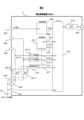
図1は、本発明の第1の実施形態に係る電池制御装置を含んだ電池システムの構成を示す図である。図1に示す電池システムは、車両に搭載されたインバータ1と接続されてインバータ1との間で直流電力の授受を行うものであり、高電圧リレー2、電池3、リレー制御スイッチ401、および電池制御装置5を備える。
(First embodiment)
FIG. 1 is a diagram showing the configuration of a battery system including a battery control device according to a first embodiment of the present invention. The battery system shown in FIG. 1 is connected to an
インバータ1は、車両に設けられた不図示のモータと電池3との間で、直流電力と交流電力の相互変換を行う。すなわち、電池3から供給された直流電力は、インバータ1により交流電力に変換されてモータに出力される。また、モータから供給された交流電力は、インバータ1により直流電力に変換されて電池3に出力される。
The
高電圧リレー2は、インバータ1と電池3の間に接続されており、正極側リレー201、負極側リレー203、プリチャージリレー202およびプリチャージ用抵抗204を有する。正極側リレー201は、インバータ1のプラス側配線20と電池3のプラス側配線22の間に接続されている。負極側リレー203は、インバータ1のマイナス側配線21と電池3のマイナス側配線23の間に接続されている。プリチャージリレー202は、インバータ1のマイナス側配線21と電池3のマイナス側配線23の間に、負極側リレー203と並列に接続されている。プリチャージ用抵抗204は、プリチャージリレー202と直列に接続されている。
The
正極側リレー201、プリチャージリレー202、負極側リレー203には、これらのリレーを切り替えるための励磁コイルがそれぞれ内蔵されている。正極側リレー201の励磁コイルは、電流経路12および16に接続されている。プリチャージリレー202の励磁コイルは、電流経路13および17に接続されている。負極側リレー203の励磁コイルは、電流経路14および17に接続されている。これらの各励磁コイルは、それぞれの電流経路において電流が流れているときには、その電流により磁界を発生することで、対応する各リレーをON状態に切り替える。一方、それぞれの電流経路において電流が流れていないときには、対応する各リレーをOFF状態に切り替える。これにより、各電流経路を流れる電流の有無に応じて各リレーが切り替えられる。
The
高電圧バッテリである電池3は、複数の単電池301を直並列に接続して構成されている。各単電池301は、たとえばリチウムイオン電池等の二次電池を用いて構成されている。
The
リレー制御スイッチ401は、高電圧リレー2の正極側リレー201、プリチャージリレー202、負極側リレー203にそれぞれ接続された3つのスイッチ401-1、401-2、401-3により構成されている。スイッチ401-1の一端側は、電流経路12を介して正極側リレー201の励磁コイルに接続されている。スイッチ401-2の一端側は、電流経路13を介してプリチャージリレー202の励磁コイルに接続されている。スイッチ401-3の一端側は、電流経路14を介して負極側リレー203の励磁コイルに接続されている。これらのスイッチの他端側は、いずれも車両内の低電圧電源11に接続されている。なお、低電圧電源11は、たとえば電圧12Vの電装系電源である。リレー制御スイッチ401における各スイッチの切り替え状態は、車両に搭載された不図示の上位コントローラによって制御される。
The
電池制御装置5は、電池3の各単電池301間の接続点と電圧検出線19を介して接続されており、各単電池301の電圧を検出して電池3の状態を監視する。また、電池制御装置5は、リレー制御スイッチ501を内部に有している。リレー制御スイッチ501は、高電圧リレー2の正極側リレー201に接続されたスイッチ501-1と、プリチャージリレー202および負極側リレー203に接続されたスイッチ501-2により構成されている。スイッチ501-1の一端側は、電流経路16を介して正極側リレー201の励磁コイルに接続されている。スイッチ501-2の一端側は、電流経路17を介してプリチャージリレー202の励磁コイルおよび負極側リレー203の励磁コイルに接続されている。これらのスイッチの他端側は、いずれも低電圧電源11のGNDであるシャーシGND18に接続されている。スイッチ501-1および501-2の切り替え状態は、電池制御装置5によって制御され、電池制御装置5が正常に動作している場合は常にON状態に切り替えられる。
The
以上説明したように、本実施形態の電池システムでは、リレー制御スイッチ401の3つのスイッチ401-1、401-2、401-3は、電流経路12~14上で、高電圧リレー2における各リレーの励磁コイルよりも低電圧電源11に近い側、すなわち高電位側に設けられている。一方、電池制御装置5内のリレー制御スイッチ501におけるスイッチ501-1および501-2は、電流経路16、17上で、高電圧リレー2における各リレーの励磁コイルよりもシャーシGND18に近い側、すなわち低電位側に設けられている。したがって、これらのスイッチをON状態に切り替えることで、各電流経路を介して励磁コイルに電流が流れるようにして、高電圧リレー2の各リレーをON状態に切り替えることが可能となっている。
As explained above, in the battery system of this embodiment, the three switches 401-1, 401-2, and 401-3 of the
図1の電池システムが起動されて電池制御装置5が動作を開始すると、リレー制御スイッチ501においてスイッチ501-1および501-2がON状態に切り替えられる。また、不図示の上位コントローラにより、リレー制御スイッチ401においてスイッチ401-1および401-2がON状態に切り替えられる。これにより、電流経路12および16に電流が流れて正極側リレー201がON状態に切り替えられると共に、電流経路13および17に電流が流れてプリチャージリレー202がON状態に切り替えられる。その結果、プリチャージ用抵抗204により突入電流が低減された状態で、インバータ1と電池3が接続される。その後、インバータ1内の平滑コンデンサが一定電圧以上に充電されると、スイッチ401-3がON状態に切り替えられると共に、スイッチ401-2がOFF状態に切り替えられる。これにより、電流経路14および17に電流が流れて負極側リレー203がON状態に切り替えられると共に、電流経路13の電流は遮断されてプリチャージリレー202がOFF状態に切り替えられる。その結果、インバータ1と電池3の接続が完了し、インバータ1と電池3の間で直流電力の授受が行われる。
When the battery system of FIG. 1 is activated and
なお、図1に示した電池システムの例では、プリチャージリレー202およびプリチャージ用抵抗204は、インバータ1のマイナス側配線21と電池3のマイナス側配線23の間に、負極側リレー203と並列に接続されている。しかしながら、インバータ1のプラス側配線20と電池3のプラス側配線22の間に、正極側リレー201と並列に、プリチャージリレー202およびプリチャージ用抵抗204を接続してもよい。また、突入電流が特に問題とならない場合は、プリチャージリレー202およびプリチャージ用抵抗204を設けなくてもよい。
Note that in the example of the battery system shown in FIG. It is connected to the. However, a
ここで、インバータ1と電池3の接続が完了した後、電池3や電池制御装置5において何らかの異常が発生したとする。この場合、不図示の上位コントローラにより、リレー制御スイッチ401の各スイッチがOFF状態に切り替えられる。また、電池制御装置5は、リレー制御スイッチ501のスイッチ501-1および501-2をOFF状態に切り替える。その結果、電流経路12および16を流れる電流が遮断され、正極側リレー201がOFF状態に切り替えられると共に、電流経路14および17を流れる電流が遮断され、負極側リレー203がOFF状態に切り替えられる。このように、本実施形態の電池システムでは、インバータ1と電池3の接続遮断を行う系統を、リレー制御スイッチ401の系統と、電池制御装置5内のリレー制御スイッチ501の系統とで、二重系としている。したがって、いずれか一方の系統において故障が発生した場合でも、電池3が過充電や過放電に至るのを確実に防止することができる。
Here, it is assumed that after the connection between the
図2は、電池制御装置5の内部回路の一例を示す図である。電池制御装置5は、図1に示したリレー制御スイッチ501を構成するスイッチ501-1および501-2を有すると共に、符号502~507、520の各端子と、電源回路508、監視回路510、モニタ回路514-1および514-2、駆動回路516、マイコン518、CANドライバ519とを有する。
FIG. 2 is a diagram showing an example of the internal circuit of the
端子502は、電池制御装置5の動作電源を入力するための端子である。端子502から入力された動作電源は、電源回路508により電圧変換され、符号509に示すように、マイコン518の電源VCCとしてマイコン518に出力される。
The terminal 502 is a terminal for inputting the operating power of the
端子503、504は、図1の電流経路16、17にそれぞれ接続されている。スイッチ501-1および501-2は、端子503、504と、電流経路16、17とをそれぞれ介して、図1の正極側リレー201の励磁コイルと、プリチャージリレー202の励磁コイルおよび負極側リレー203の励磁コイルとにそれぞれ接続されている。
端子505、506、507は、いずれもシャーシGND18に接続されている。スイッチ501-1および501-2は、端子505および506を介して、シャーシGND18にそれぞれ接続されている。マイコン518は、端子507を介して、シャーシGND18に接続されている。
このように、電池制御装置5では、各リレーの励磁コイルへ接続するための端子(端子503および504)や、シャーシGND18へ接続するための端子(端子505、506および507)を、それぞれ複数ずつ設けている。その理由は、各端子の許容電流をオーバーしないように余裕を持った構成とするためである。また、端子電流が大きくなると接触抵抗による電圧ドロップで回路動作に悪影響を及ぼすことが考えられるため、それを防止する目的もある。
In this way, the
監視回路510は、信号線512を介してマイコン518との間で所定のデータを入出力することにより、マイコン518の動作を監視する回路である。たとえば、マイコン518の暴走や、マイコン518がデュアルコアを搭載したマイコンであれば、デュアルコア間の演算不一致などを監視することで、監視回路510はマイコン518の動作が異常であるか否かを監視している。これらのマイコン518の動作異常が発生した場合、監視回路510は、リセット信号511を出力してマイコン518をリセットしたり、マイコンFail信号513を駆動回路516に出力したりする。
The
モニタ回路514-1および514-2は、スイッチ501-1、501-2の状態をそれぞれモニタし、その結果をマイコン518に出力する。
Monitor circuits 514-1 and 514-2 monitor the states of switches 501-1 and 501-2, respectively, and output the results to
駆動回路516は、マイコン518から出力される駆動信号517、または監視回路510から出力されるマイコンFail信号513に応じて、スイッチ501-1および501-2をそれぞれON状態またはOFF状態に切り替える。具体的には、マイコン518から駆動信号517が出力されると、駆動回路516はスイッチ501-1および501-2をそれぞれON状態に切り替える。また、監視回路510からマイコンFail信号513が出力されると、駆動信号517の出力の有無に関わらず、駆動回路516はスイッチ501-1および501-2をそれぞれOFF状態に切り替える。これにより、マイコン518の動作異常が発生した場合には、図1の正極側リレー201および負極側リレー203をそれぞれOFF状態に切り替えて、インバータ1と電池3の接続が遮断されるようにする。
The
端子520は、車両内に設けられた不図示のCAN(Controller Area Network)に接続されている。CANドライバ519は、マイコン518から出力されるデータをCAN信号に変換し、端子520を介してCANに送信すると共に、端子520を介してCANから受信したCAN信号をデータに変換し、マイコン518に出力する。電池制御装置5は、このCANドライバ519によるCAN信号を用いて、前述の上位コントローラとの間で通信を行うことができる。
The terminal 520 is connected to a CAN (Controller Area Network) (not shown) provided in the vehicle. The
なお、図2に示した構成例では、スイッチ501-1および501-2に対して駆動回路516を一つだけ設けたが、各スイッチに対して駆動回路516をそれぞれ設けるようにしてもよい。
Note that in the configuration example shown in FIG. 2, only one
次に、本実施形態の電池システムの動作シーケンスについて、図3、4および5の各フローチャートを用いて説明する。 Next, the operation sequence of the battery system of this embodiment will be explained using the flowcharts of FIGS. 3, 4, and 5.
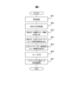
図3は、電池制御装置5が正常に起動した場合の動作シーケンスを示すフローチャートである。ステップ801で車両が起動し、ステップ802で電池制御装置5が正常に起動すると、ステップ803で電池制御装置5は、マイコン518から駆動回路516へ駆動信号517を出力し、内蔵しているスイッチ501-1および501-2をON状態に切り替える。続いて、ステップ804で電池制御装置5は、マイコン518からCANドライバ519へ所定のデータを出力し、高電圧リレー2のON状態への切り替えを許可するCAN信号であるリレーON許可信号を不図示の上位コントローラへ出力する。
FIG. 3 is a flowchart showing the operation sequence when the
ステップ804で電池制御装置5から送信されたリレーON許可信号を受信すると、ステップ805で上位コントローラは、リレー制御スイッチ401の各スイッチをON状態に切り替える。このとき前述のように、最初にスイッチ401-1および401-2をON状態に切り替え、インバータ1内の平滑コンデンサが一定電圧以上に充電された後に、スイッチ401-3をON状態に切り替えると共に、スイッチ401-2をOFF状態に切り替える。このリレー制御スイッチ401の切り替えに応じて各電流経路に電流が流れることにより、ステップ806で高電圧リレー2の各リレーが順次ON状態に切り替えられ、ステップ807で電池3の充放電が開始される。
Upon receiving the relay ON permission signal transmitted from the
図4は、電池制御装置5の起動時に異常を検知した場合の動作シーケンスを示すフローチャートである。この場合、ステップ811で車両が起動すると、ステップ812で電池制御装置5が起動時に異常を検知する。なお、電池制御装置5が検知する異常には、軽微な故障から重篤な故障まで多様な種類のものが考えられるが、ここでは特にインバータ1と電池3の接続を遮断すべき重篤な故障を想定している。軽い故障に対しては、この限りでは無い。
FIG. 4 is a flowchart showing an operation sequence when an abnormality is detected when the
ステップ812で電池制御装置5が異常を検知すると、ステップ813で電池制御装置5は、マイコン518から駆動回路516へ駆動信号517を出力せずに、内蔵しているスイッチ501-1および501-2をON状態に切り替えない。続いて、ステップ814で電池制御装置5は、マイコン518からCANドライバ519へ所定のデータを出力せずに、リレーON許可信号を上位コントローラへ出力しない。
When the
ステップ814で電池制御装置5からリレーON許可信号が送信されないため、ステップ815で上位コントローラは、リレー制御スイッチ401の各スイッチをON状態に切り替えない。その結果、ステップ816で高電圧リレー2の各リレーがON状態に切り替えられず、ステップ817で電池3の充放電が開始されない。
Since the relay ON permission signal is not transmitted from the
図5は、電池制御装置5が正常に起動した後に異常を検知した場合の動作シーケンスを示すフローチャートである。この場合、ステップ801で車両が起動すると、ステップ802~807までは図3と同じ内容の動作がそれぞれ行われ、電池3の充放電が開始される。その後、ステップ821で車両の走行中に電池制御装置5が異常を検知すると、ステップ822で電池制御装置5は、マイコン518からCANドライバ519へ所定のデータを出力し、高電圧リレー2のOFF状態への切り替えを要求するCAN信号を上位コントローラへ出力する。続いて一定時間経過後に、ステップ823で電池制御装置5は、マイコン518から駆動回路516への駆動信号517の出力を停止し、内蔵しているスイッチ501-1および501-2をOFF状態に切り替える。
FIG. 5 is a flowchart showing an operation sequence when an abnormality is detected after the
ステップ822で電池制御装置5から送信された高電圧リレー2のOFF状態への切り替え要求を受けて、上位コントローラがリレー制御スイッチ401の各スイッチをOFF状態に切り替えるか、または、ステップ823で電池制御装置5がスイッチ501-1および501-2をOFF状態に切り替えることにより、各電流経路に流れる電流が遮断される。その結果、ステップ824で高電圧リレー2の各リレーがOFF状態に切り替えられ、ステップ825で電池3の充放電が停止される。
Upon receiving the request to switch the
(第2の実施形態)
図6は、本発明の第2の実施形態に係る電池制御装置を含んだ電池システムの構成を示す図である。本実施形態の電池システムでは、図1に示した第1の実施形態の電池システムと比べて、リレー制御スイッチ401における3つのスイッチ401-1、401-2、401-3の励磁コイルに接続されていない他端側が、シャーシGND18に接続されている点と、電池制御装置5内に設けられたリレー制御スイッチ501におけるスイッチ501-1および501-2の励磁コイルに接続されていない他端側が、低電圧電源11に接続されている点とが異なっている。
(Second embodiment)
FIG. 6 is a diagram showing the configuration of a battery system including a battery control device according to a second embodiment of the present invention. In the battery system of this embodiment, compared to the battery system of the first embodiment shown in FIG. The other end side that is not connected to the
このように、本実施形態の電池システムでは、リレー制御スイッチ401の3つのスイッチ401-1、401-2、401-3は、電流経路12~14上で、高電圧リレー2における各リレーの励磁コイルよりもシャーシGND18に近い側、すなわち低電位側に設けられている。一方、電池制御装置5内のリレー制御スイッチ501におけるスイッチ501-1および501-2は、電流経路16、17上で、高電圧リレー2における各リレーの励磁コイルよりも低電圧電源11に近い側、すなわち高電位側に設けられている。したがって、第1の実施形態と同様に、これらのスイッチをON状態に切り替えることで、各電流経路を介して励磁コイルに電流が流れるようにして、高電圧リレー2の各リレーをON状態に切り替えることが可能となっている。
In this way, in the battery system of this embodiment, the three switches 401-1, 401-2, and 401-3 of the
なお、本実施形態における各スイッチの切り替え方法は、第1の実施形態で説明したのと同様である。そのため、本実施形態の電池システムでも、インバータ1と電池3の接続遮断を行う系統を、リレー制御スイッチ401の系統と、電池制御装置5内のリレー制御スイッチ501の系統とで、二重系としている。したがって、いずれか一方の系統において故障が発生した場合でも、電池3が過充電や過放電に至るのを確実に防止することができる。
Note that the method of switching each switch in this embodiment is the same as that described in the first embodiment. Therefore, in the battery system of this embodiment as well, the system for disconnecting the connection between the
以上説明した本発明の実施形態によれば、以下の作用効果を奏する。 According to the embodiment of the present invention described above, the following effects are achieved.
(1)電池システムは、電池3とインバータ1の間の接続を導通または遮断するための高電圧リレー2と、高電圧リレー2を切り替えるための電流経路12~14、16、17上にそれぞれ設けられた複数のリレー制御スイッチ401および501と、を備える。電池制御装置5は、この電池システムにおいて用いられ、電池3の状態を監視する。リレー制御スイッチ401および501は、電流経路12~14、16、17上で互いに直列に接続されており、このうちリレー制御スイッチ501は、電池制御装置5内に設けられている。電池制御装置5は、このリレー制御スイッチ501の切り替え状態を制御する。このようにしたので、電池3とインバータ1の間の接続を導通または遮断する高電圧リレー2の制御を行う回路である上位コントローラに故障が発生した場合でも、電池3が過充電や過放電に至るのを確実に防止することができる。
(1) The battery system includes a
(2)電池3とインバータ1の間に、高電圧リレー2として、正極側リレー201、負極側リレー203およびプリチャージリレー202が設けられている。これらのリレーの各々に対応して、スイッチ401-1およびスイッチ501-1の組と、スイッチ401-2およびスイッチ501-2の組と、スイッチ401-3およびスイッチ501-2の組とが、それぞれ設けられている。これらのスイッチの各組は、電池制御装置5内に設けられたリレー制御スイッチ501におけるスイッチ501-1またはスイッチ501-2をそれぞれ含む。このようにしたので、電池3とインバータ1の間の接続および遮断を、安全かつ確実に行うことができる。
(2) A
(3)電流経路12~14、16、17上で互いに直列に接続されたリレー制御スイッチ401および電池制御装置5内に設けられたリレー制御スイッチ501は、一方が電流経路12~14、16、17の高電位側に接続されており、他方が電流経路12~14、16、17の低電位側に接続されている。このようにしたので、いずれかのスイッチをOFF状態に切り替えることで、電流経路12~14、16、17に流れる電流を遮断し、高電圧リレー2を確実にOFF状態とすることができる。
(3) The
(4)電流経路12~14、16、17上には、これらの電流経路を流れる電流の有無に応じて高電圧リレー2を切り替える各リレーの励磁コイルが配置されている。電池制御装置5内に設けられたリレー制御スイッチ501は、電流経路16、17上で励磁コイルよりも高電位側または低電位側に設けられている。このようにしたので、リレー制御スイッチ501をON状態に切り替えることで、励磁コイルに電流を流して高電圧リレー2の各リレーをON状態に切り替えることができる。
(4) Excitation coils for each relay are arranged on the
以上説明した実施形態や各種変形例はあくまで一例であり、発明の特徴が損なわれない限り、本発明はこれらの内容に限定されるものではない。また、上記では種々の実施形態や変形例を説明したが、本発明はこれらの内容に限定されるものではない。本発明の要旨を逸脱しない範囲における変更があっても、本発明の技術的思想の範囲内で考えられるものであれば本発明の範囲内に含まれる。 The embodiments and various modifications described above are merely examples, and the present invention is not limited to these contents as long as the characteristics of the invention are not impaired. Furthermore, although various embodiments and modifications have been described above, the present invention is not limited to these. Even if there are changes that do not depart from the gist of the present invention, they are included within the scope of the present invention as long as they are considered within the scope of the technical idea of the present invention.
1 インバータ
2 高電圧リレー
3 電池
5 電池制御装置
11 低電圧電源
12,13,14,16,17 電流経路
18 シャーシGND
19 電圧検出線
20 インバータのプラス側配線
21 インバータのマイナス側配線
22 電池のプラス側配線
23 電池のマイナス側配線
201 正極側リレー
202 プリチャージリレー
203 負極側リレー
204 プリチャージ用抵抗
301 単電池
401,501 リレー制御スイッチ
1
19
Claims (4)
前記複数のスイッチは、前記電池制御装置内に設けられた第1のスイッチと、前記電池制御装置外に設けられた第2のスイッチと、を含み、
前記第1のスイッチと前記第2のスイッチとは、前記電流経路上で互いに直列に接続され、互いに一方のみのスイッチ切り替えにより前記リレーをオフ状態に切り替え可能に構成されており、
前記電池制御装置は、前記電池の異常を検知した場合、および、前記電池制御装置自身の異常を検知した場合に、前記第2のスイッチの切り替え状態の制御を行う上位制御装置に対して前記リレーの遮断要求を送信すると共に、前記第1のスイッチをオフ状態に切り替える電池制御装置。 It is used in a battery system that includes a relay for conducting or breaking a connection between a battery and an inverter, and a plurality of switches each provided on a current path for switching the relay. A battery control device for monitoring,
The plurality of switches include a first switch provided within the battery control device and a second switch provided outside the battery control device,
The first switch and the second switch are connected to each other in series on the current path, and are configured to be able to turn off the relay by switching only one of the switches,
The battery control device transmits the relay to a higher-level control device that controls the switching state of the second switch when detecting an abnormality in the battery and when detecting an abnormality in the battery control device itself. A battery control device that transmits a cutoff request for the first switch and switches the first switch to an off state .
正常起動した場合、前記上位制御装置に対して前記リレーのオン状態への切り替えを許可する許可信号を送信すると共に、前記第1のスイッチをオン状態に切り替え、If the system starts up normally, transmitting a permission signal to the upper control device to permit switching of the relay to an on state, and switching the first switch to an on state;
起動時に前記電池または前記電池制御装置自身の異常を検知した場合、前記上位制御装置に対して前記許可信号を送信せずに、前記第1のスイッチをオン状態に切り替えない電池制御装置。A battery control device that does not turn on the first switch without transmitting the permission signal to the higher-level control device when an abnormality of the battery or the battery control device itself is detected during startup.
前記電池と前記インバータの間に、前記リレーが複数設けられており、
複数の前記リレーの各々に対応して、前記複数のスイッチの組がそれぞれ設けられており、
前記複数のスイッチの各組は、前記第1のスイッチおよび前記第2のスイッチをそれぞれ含む電池制御装置。 The battery control device according to claim 1 or 2 ,
A plurality of the relays are provided between the battery and the inverter,
A set of the plurality of switches is provided corresponding to each of the plurality of relays,
A battery control device in which each set of the plurality of switches includes the first switch and the second switch .
前記電流経路上には、前記電流経路を流れる電流の有無に応じて前記リレーを切り替える励磁コイルが配置されており、
前記第1のスイッチは、前記電流経路上で前記励磁コイルよりも高電位側または低電位側に設けられており、
前記第2のスイッチは、前記電流経路上で前記励磁コイルを間に挟んで前記第1のスイッチと直列に接続されている電池制御装置。 The battery control device according to claim 1 or 2 ,
An excitation coil that switches the relay depending on the presence or absence of current flowing through the current path is disposed on the current path,
The first switch is provided on the current path on a higher potential side or a lower potential side than the excitation coil ,
The second switch is a battery control device connected in series with the first switch on the current path with the excitation coil interposed therebetween.
Priority Applications (1)
| Application Number | Priority Date | Filing Date | Title |
|---|---|---|---|
| JP2019214097A JP7373372B2 (en) | 2019-11-27 | 2019-11-27 | battery control device |
Applications Claiming Priority (1)
| Application Number | Priority Date | Filing Date | Title |
|---|---|---|---|
| JP2019214097A JP7373372B2 (en) | 2019-11-27 | 2019-11-27 | battery control device |
Publications (2)
| Publication Number | Publication Date |
|---|---|
| JP2021087280A JP2021087280A (en) | 2021-06-03 |
| JP7373372B2 true JP7373372B2 (en) | 2023-11-02 |
Family
ID=76085934
Family Applications (1)
| Application Number | Title | Priority Date | Filing Date |
|---|---|---|---|
| JP2019214097A Active JP7373372B2 (en) | 2019-11-27 | 2019-11-27 | battery control device |
Country Status (1)
| Country | Link |
|---|---|
| JP (1) | JP7373372B2 (en) |
Citations (3)
| Publication number | Priority date | Publication date | Assignee | Title |
|---|---|---|---|---|
| JP2015050894A (en) | 2013-09-04 | 2015-03-16 | 株式会社デンソー | Feeding vehicle and feeding system |
| JP2018113825A (en) | 2017-01-13 | 2018-07-19 | 三共オートサービス株式会社 | Control unit for modified type electric vehicle and modified type electric vehicle |
| JP2018182920A (en) | 2017-04-14 | 2018-11-15 | 日立建機株式会社 | Electricity storage device controller, electric system, and construction machine |
-
2019
- 2019-11-27 JP JP2019214097A patent/JP7373372B2/en active Active
Patent Citations (3)
| Publication number | Priority date | Publication date | Assignee | Title |
|---|---|---|---|---|
| JP2015050894A (en) | 2013-09-04 | 2015-03-16 | 株式会社デンソー | Feeding vehicle and feeding system |
| JP2018113825A (en) | 2017-01-13 | 2018-07-19 | 三共オートサービス株式会社 | Control unit for modified type electric vehicle and modified type electric vehicle |
| JP2018182920A (en) | 2017-04-14 | 2018-11-15 | 日立建機株式会社 | Electricity storage device controller, electric system, and construction machine |
Also Published As
| Publication number | Publication date |
|---|---|
| JP2021087280A (en) | 2021-06-03 |
Similar Documents
| Publication | Publication Date | Title |
|---|---|---|
| JP6142894B2 (en) | Vehicle power supply | |
| JP5470073B2 (en) | Battery control device and battery system | |
| JP5523480B2 (en) | Highly reliable drive battery | |
| CN109649216B (en) | Automatic connection of drive battery | |
| CN100454466C (en) | Method and apparatus for detecting welding of a relay contact | |
| US11984719B2 (en) | Quick battery disconnect system for high current circuits | |
| JP5860886B2 (en) | Battery control device, power storage device, and vehicle | |
| JP6087675B2 (en) | Battery module | |
| WO2013094015A1 (en) | Battery monitoring and control integrated circuit and a battery system | |
| KR20130081215A (en) | Power supply device | |
| JP6581706B2 (en) | Battery management device | |
| GB2467231A (en) | High voltage battery controller with isolation | |
| JP7425997B2 (en) | power distribution module | |
| US20140042936A1 (en) | Battery Module, Battery Management System, System for Supplying a Drive of a Machine Suitable for Generating Torque with Electrical Energy, and a Motor Vehicle | |
| CN111699605A (en) | Battery control device | |
| JP7373372B2 (en) | battery control device | |
| JP7349510B2 (en) | Automotive battery system | |
| JP6668210B2 (en) | Power supply control device and power supply system | |
| JP6972140B2 (en) | Power control device and control method of power control device | |
| WO2019193637A1 (en) | Battery device and vehicle | |
| JP7558486B2 (en) | DC Circuit Switching Device | |
| JP7172977B2 (en) | Control device for in-vehicle power supply | |
| JP2023053717A (en) | Battery charging device of vehicle | |
| JP2019110701A (en) | Management device of battery of vehicle | |
| KR20180112484A (en) | Battery management apparatus and method having added redundant battery |
Legal Events
| Date | Code | Title | Description |
|---|---|---|---|
| A621 | Written request for application examination |
Free format text: JAPANESE INTERMEDIATE CODE: A621 Effective date: 20221019 |
|
| A977 | Report on retrieval |
Free format text: JAPANESE INTERMEDIATE CODE: A971007 Effective date: 20230614 |
|
| A131 | Notification of reasons for refusal |
Free format text: JAPANESE INTERMEDIATE CODE: A131 Effective date: 20230620 |
|
| A521 | Request for written amendment filed |
Free format text: JAPANESE INTERMEDIATE CODE: A523 Effective date: 20230725 |
|
| TRDD | Decision of grant or rejection written | ||
| A01 | Written decision to grant a patent or to grant a registration (utility model) |
Free format text: JAPANESE INTERMEDIATE CODE: A01 Effective date: 20230926 |
|
| A61 | First payment of annual fees (during grant procedure) |
Free format text: JAPANESE INTERMEDIATE CODE: A61 Effective date: 20231023 |
|
| R150 | Certificate of patent or registration of utility model |
Ref document number: 7373372 Country of ref document: JP Free format text: JAPANESE INTERMEDIATE CODE: R150 |