EP3610251B1 - Partikelsensor - Google Patents
Partikelsensor Download PDFInfo
- Publication number
- EP3610251B1 EP3610251B1 EP18717544.3A EP18717544A EP3610251B1 EP 3610251 B1 EP3610251 B1 EP 3610251B1 EP 18717544 A EP18717544 A EP 18717544A EP 3610251 B1 EP3610251 B1 EP 3610251B1
- Authority
- EP
- European Patent Office
- Prior art keywords
- protective sleeve
- exhaust gas
- inner protective
- gas
- gas inlet
- Prior art date
- Legal status (The legal status is an assumption and is not a legal conclusion. Google has not performed a legal analysis and makes no representation as to the accuracy of the status listed.)
- Active
Links
Images



Classifications
-
- G—PHYSICS
- G01—MEASURING; TESTING
- G01N—INVESTIGATING OR ANALYSING MATERIALS BY DETERMINING THEIR CHEMICAL OR PHYSICAL PROPERTIES
- G01N15/00—Investigating characteristics of particles; Investigating permeability, pore-volume or surface-area of porous materials
- G01N15/06—Investigating concentration of particle suspensions
- G01N15/0606—Investigating concentration of particle suspensions by collecting particles on a support
-
- G—PHYSICS
- G01—MEASURING; TESTING
- G01N—INVESTIGATING OR ANALYSING MATERIALS BY DETERMINING THEIR CHEMICAL OR PHYSICAL PROPERTIES
- G01N27/00—Investigating or analysing materials by the use of electric, electrochemical, or magnetic means
- G01N27/26—Investigating or analysing materials by the use of electric, electrochemical, or magnetic means by investigating electrochemical variables; by using electrolysis or electrophoresis
- G01N27/403—Cells and electrode assemblies
- G01N27/406—Cells and probes with solid electrolytes
- G01N27/407—Cells and probes with solid electrolytes for investigating or analysing gases
- G01N27/4077—Means for protecting the electrolyte or the electrodes
-
- F—MECHANICAL ENGINEERING; LIGHTING; HEATING; WEAPONS; BLASTING
- F01—MACHINES OR ENGINES IN GENERAL; ENGINE PLANTS IN GENERAL; STEAM ENGINES
- F01N—GAS-FLOW SILENCERS OR EXHAUST APPARATUS FOR MACHINES OR ENGINES IN GENERAL; GAS-FLOW SILENCERS OR EXHAUST APPARATUS FOR INTERNAL-COMBUSTION ENGINES
- F01N11/00—Monitoring or diagnostic devices for exhaust-gas treatment apparatus
-
- G—PHYSICS
- G01—MEASURING; TESTING
- G01N—INVESTIGATING OR ANALYSING MATERIALS BY DETERMINING THEIR CHEMICAL OR PHYSICAL PROPERTIES
- G01N11/00—Investigating flow properties of materials, e.g. viscosity, plasticity; Analysing materials by determining flow properties
-
- G—PHYSICS
- G01—MEASURING; TESTING
- G01N—INVESTIGATING OR ANALYSING MATERIALS BY DETERMINING THEIR CHEMICAL OR PHYSICAL PROPERTIES
- G01N15/00—Investigating characteristics of particles; Investigating permeability, pore-volume or surface-area of porous materials
- G01N15/06—Investigating concentration of particle suspensions
- G01N15/0656—Investigating concentration of particle suspensions using electric, e.g. electrostatic methods or magnetic methods
-
- G—PHYSICS
- G01—MEASURING; TESTING
- G01N—INVESTIGATING OR ANALYSING MATERIALS BY DETERMINING THEIR CHEMICAL OR PHYSICAL PROPERTIES
- G01N27/00—Investigating or analysing materials by the use of electric, electrochemical, or magnetic means
- G01N27/02—Investigating or analysing materials by the use of electric, electrochemical, or magnetic means by investigating impedance
- G01N27/04—Investigating or analysing materials by the use of electric, electrochemical, or magnetic means by investigating impedance by investigating resistance
- G01N27/06—Investigating or analysing materials by the use of electric, electrochemical, or magnetic means by investigating impedance by investigating resistance of a liquid
- G01N27/07—Construction of measuring vessels; Electrodes therefor
-
- F—MECHANICAL ENGINEERING; LIGHTING; HEATING; WEAPONS; BLASTING
- F01—MACHINES OR ENGINES IN GENERAL; ENGINE PLANTS IN GENERAL; STEAM ENGINES
- F01N—GAS-FLOW SILENCERS OR EXHAUST APPARATUS FOR MACHINES OR ENGINES IN GENERAL; GAS-FLOW SILENCERS OR EXHAUST APPARATUS FOR INTERNAL-COMBUSTION ENGINES
- F01N2560/00—Exhaust systems with means for detecting or measuring exhaust gas components or characteristics
- F01N2560/02—Exhaust systems with means for detecting or measuring exhaust gas components or characteristics the means being an exhaust gas sensor
-
- F—MECHANICAL ENGINEERING; LIGHTING; HEATING; WEAPONS; BLASTING
- F01—MACHINES OR ENGINES IN GENERAL; ENGINE PLANTS IN GENERAL; STEAM ENGINES
- F01N—GAS-FLOW SILENCERS OR EXHAUST APPARATUS FOR MACHINES OR ENGINES IN GENERAL; GAS-FLOW SILENCERS OR EXHAUST APPARATUS FOR INTERNAL-COMBUSTION ENGINES
- F01N2560/00—Exhaust systems with means for detecting or measuring exhaust gas components or characteristics
- F01N2560/05—Exhaust systems with means for detecting or measuring exhaust gas components or characteristics the means being a particulate sensor
-
- G—PHYSICS
- G01—MEASURING; TESTING
- G01N—INVESTIGATING OR ANALYSING MATERIALS BY DETERMINING THEIR CHEMICAL OR PHYSICAL PROPERTIES
- G01N15/00—Investigating characteristics of particles; Investigating permeability, pore-volume or surface-area of porous materials
- G01N2015/0042—Investigating dispersion of solids
- G01N2015/0046—Investigating dispersion of solids in gas, e.g. smoke
-
- Y—GENERAL TAGGING OF NEW TECHNOLOGICAL DEVELOPMENTS; GENERAL TAGGING OF CROSS-SECTIONAL TECHNOLOGIES SPANNING OVER SEVERAL SECTIONS OF THE IPC; TECHNICAL SUBJECTS COVERED BY FORMER USPC CROSS-REFERENCE ART COLLECTIONS [XRACs] AND DIGESTS
- Y02—TECHNOLOGIES OR APPLICATIONS FOR MITIGATION OR ADAPTATION AGAINST CLIMATE CHANGE
- Y02T—CLIMATE CHANGE MITIGATION TECHNOLOGIES RELATED TO TRANSPORTATION
- Y02T10/00—Road transport of goods or passengers
- Y02T10/10—Internal combustion engine [ICE] based vehicles
- Y02T10/40—Engine management systems
Definitions
- an exhaust gas sensor which comprises a sleeve-shaped sensor housing, a sensor element fixed in the sensor housing, which protrudes beyond the sensor housing on the exhaust side, and a sleeve-shaped protective tube which is attached to the sensor housing on the exhaust side, the protective tube consisting of an inner protective sleeve and an outer protective sleeve exists, wherein the inner protective sleeve surrounds an exhaust-side end region of the sensor element, wherein the outer protective sleeve surrounds the inner protective sleeve at least in some areas, so that an annular space is formed between the outer protective sleeve and the inner protective sleeve, the outer protective sleeve and the inner protective sleeve each having a gas outlet and a Have gas inlet and a flow through the protective tube from the gas inlet of the outer protective sleeve into the annular space, from there through the gas inlet of the inner protective sleeve into the
- the DE 10 2016 102 597 A1 discloses a system for detecting particulate matter in an exhaust system of a vehicle comprising a first outer tube having a plurality of suction openings on an upstream surface and a second inner tube having a plurality of suction openings on a downstream surface, and a particulate matter sensor located within the second inner tube is positioned.
- the present invention relates to an exhaust gas sensor as defined in claim 1. Preferred features of the exhaust gas sensor are described in the dependent claims. A use of the exhaust gas sensor is defined in claim 10. This is a particle sensor for detecting the concentration of solid components of a gas, for example the concentration of soot in an exhaust gas from an internal combustion engine.
- the present invention is based on the knowledge that the sensitivity and dynamics of the exhaust gas sensor is fundamentally influenced by its orientation in an exhaust gas line, in particular with regard to the rotation of the exhaust gas sensor about its longitudinal axis, which is preferably oriented perpendicular to the main flow direction in the exhaust gas line is. It was recognized that, for example, in the exhaust gas sensor known from the prior art, exhaust gas preferably enters the interior of the protective tube through the upstream gas inlet openings of the inner and outer protective sleeve and the sensor element preferably flows in a directed direction from these gas inlet openings.
- exhaust gas preferably enters the interior of the protective tube through the downstream gas inlet openings of the inner and outer protective sleeve and the sensor element preferably flows in a directed direction from these gas inlet openings.
- these sensors result in different sensitivity and dynamics of the exhaust gas sensor.
- the accuracy of the exhaust gas sensor when mounted in an undefined oriented manner in an exhaust pipe, in particular when the exhaust gas sensor is rotated in an undefined manner about its longitudinal axis, is increased in this way.
- the present invention is therefore also based on the inventors' knowledge that soot particles contained in the exhaust gas can be deposited on the sensor element particularly efficiently if the exhaust gas is directed at the sensor element with the highest possible flow speed. A high proportion of the soot particles contained in the exhaust gas reach very close to the sensor element and are deposited on it at a high rate.
- the flow speed at which the exhaust gas is directed towards the sensor element can be increased to an adequate extent by the gas inlet of the inner protective sleeve forming the smallest flow cross section when flowing through the protective tube, in particular if the gas inlet is on an axial direction Height of the sensor element is arranged.
- the throttling effect of the gas inlet of the inner protective tube that is realized in this way maximizes a pressure difference between the interior of the inner protective sleeve and the annular space, which gives the exhaust gas a significant acceleration in the direction of the sensor element.
- the present invention can particularly increase the sensitivity of a particle sensor.
- the exhaust gas sensor has a sleeve-shaped sensor housing, which in particular has a through hole and in this respect defines in particular an axis or longitudinal axis and an axial direction within the scope of the invention.
- an orientation of this axis or this axial direction is referred to as the exhaust side.
- the sleeve-shaped sensor housing can be metallic, for example.
- the sleeve-shaped sensor housing can, for example, have an external thread and/or an external hexagon profile.
- the exhaust gas sensor can be mounted in particular in this or in particular in another way in an exhaust pipe, in particular of an internal combustion engine.
- a sensor element is fixed in the sensor housing.
- the sensor element is in particular at least partially fixed in the through hole of the sensor housing.
- the sensor element protrudes beyond the sensor housing on the exhaust side. It is provided that a sensitive area of the sensor element, a known interdigital electrode structure, is arranged on the part of the sensor element that protrudes beyond the sensor housing on the exhaust side.
- the exhaust gas sensor according to the invention has a sleeve-shaped protective tube which is attached to the sensor housing on the exhaust side, for example welded.
- the protective tube can, for example, be welded from the radial outside to a collar of the sensor housing.
- the protective tube can, for example, be metallic; for example, it can be composed of several deep-drawn parts.
- the protective tube consists of two protective sleeves, an inner protective sleeve and an outer protective sleeve.
- the exhaust gas sensor can have a further protective sleeve, which interacts in particular with the protective tube and/or the inner protective sleeve and the outer protective sleeve, for example at least partially surrounding them.
- the inner protective sleeve and the outer protective sleeve each have the basic shape of a sleeve. In particular, there is at least one passage in an axial direction of the respective sleeve.
- the inner protective sleeve and the outer protective sleeve each individually and/or as a whole, have a basic shape that is essentially rotationally symmetrical.
- the Sleeve-shaped housings, the inner protective sleeve and/or the outer protective sleeve and in particular also the sensor element can, for example, be arranged coaxially to one another with respect to their basic structure.
- the inner protective sleeve is particularly attached to the sensor housing on the exhaust side, for example welded.
- the inner protective sleeve surrounds an exhaust-side end region of the sensor element, for example an exhaust-side end region of the sensor element, on which a sensitive region of the sensor element, in particular the sensitive region already explained above, is arranged.
- the outer protective sleeve is fastened, in particular on the exhaust side, to the sensor housing, for example welded, for example together with the inner protective sleeve by a single circumferential weld seam.
- the outer protective sleeve surrounds the inner protective sleeve at least in some areas.
- at least parts of the outer protective sleeve are arranged radially and/or axially outside the exhaust gas side, in particular on the opposite side as seen from the sensor element, of the inner protective sleeve.
- the outer protective sleeve only accommodates a part of the inner protective sleeve close to the housing in its interior, while the inner protective sleeve penetrates the outer protective sleeve and projects beyond it axially in the exhaust gas direction.
- outer protective sleeve and the inner protective sleeve are arranged both radially and axially outside the inner protective sleeve, in particular on the opposite side as seen from the sensor element.
- annular space is formed between the outer protective sleeve and the inner protective sleeve.
- An annular space is understood to mean, in particular, a space between two, in particular concentric, at least partially nested sleeves, for example cylinders. It can for example, a hollow cylindrical space.
- the projection of the annular space in the axial direction is an annular surface, which is delimited in particular by two concentric circles.
- the radii of the concentric circles can form a ratio that is between 0.35 and 0.7.
- the outer protective sleeve and the inner protective sleeve each have a gas outlet and a gas inlet.
- a gas inlet of the outer protective sleeve and a gas inlet of the inner protective sleeve and a gas outlet of the outer protective sleeve and a gas outlet of the inner protective sleeve are provided.
- Such a gas inlet or such a gas outlet of the protective sleeve in question can in particular be at least one opening in the protective sleeve in question, i.e. exactly one opening or a plurality of openings in each case, the opening or openings in particular allowing a macroscopic gas passage from the one outside of the sleeve in question represent an inside of the sleeve in question.
- these openings parallel to one another, allow a macroscopic passage of gas from an outside of the sleeve in question to an inside of the sleeve in question.
- the openings can fundamentally point in any direction, for example in the axial direction or in the radial direction.
- the gas inlet of the outer protective sleeve can, for example, consist of a large number of openings arranged regularly along the circumference of the outer protective sleeve.
- the gas inlet of the inner protective sleeve can, for example, consist of a large number of openings arranged regularly along the circumference of the inner protective sleeve.
- the gas outlet of the outer protective sleeve can, for example, consist of a central opening on the exhaust gas side.
- the gas outlet of the inner protective sleeve can, for example, consist of a central exhaust-side opening or consist of a plurality of openings which are arranged on an exhaust-side bottom of the inner protective sleeve, also known as a baffle plate.
- gas inlets and gas outlets are assigned flow cross sections. In the case of a single opening this is the geometric cross section of the opening, in the case of several openings this is the sum of the geometric cross sections of the openings in question.
- the openings in the protective sleeves are assigned to gas inlets and gas outlets.
- “Mandatory” means in particular that flow in a different order or via other paths is constructively excluded.
- the annular space communicates directly with an area outside the outer protective sleeve only via the gas inlet of the outer protective sleeve and / or the annular space communicates directly with the interior of the inner protective sleeve only via the gas inlet of the inner protective sleeve and / or that the interior of the inner protective sleeve communicates with an area outside the exhaust gas sensor through the gas outlets of the outer and inner protective sleeves, without first communicating again with the annular space.
- the flow through the protective tube takes place with regard to the gas inlets and gas outlets, i.e. apart from the parallel passage through several openings belonging to a gas inlet and a gas outlet, due to the structure of the protective tube, in particular only in the sequence defined in this way on a particularly linear and especially unbranched path.
- the flow through the protective tube can in particular be driven by this be that the gas outlet of the inner or outer protective sleeve is arranged on the exhaust side of the gas inlet of the outer protective sleeve, i.e., in particular when installing the exhaust gas sensor on the wall of an exhaust pipe, at a location with lower static pressure.
- the flow influence by the exhaust gas sensor itself, in particular by the protective tube itself, in particular a braking of the flow in the area of the gas inlet of the outer protective sleeve can also bring about or intensify this effect.
- the gas inlet of the inner protective sleeve is arranged in particular at the axial height of the sensor element.
- the gas inlet of the inner protective sleeve can be arranged at the axial height of a sensitive area of the sensor element, in particular the sensitive area already explained above.
- there is a significant acceleration of the exhaust gas in the direction of the sensor element for example, in the case of a particle sensor mentioned, the deposition of particles on the sensor element and thus the sensitivity of the particle sensor increase, as explained above.
- the gas inlet of the inner protective sleeve can be arranged in particular on the axial side facing away from the exhaust gas of a sensitive area of the sensor element, in particular the sensitive area already explained above.
- the gas flowing into the interior of the inner protective sleeve is directed by a deflection element or several deflection elements onto a sensitive area of the sensor element, in particular onto the sensitive area already explained above.
- the gas inlet of the inner protective sleeve forms the smallest flow cross section when flowing through the protective tube.
- the flow cross section of the gas inlet is therefore smaller than all others in the Cross sections flowed through the protective tube, in particular each smaller than the flow cross section of the gas outlet of the outer protective sleeve, the flow cross section of the gas inlet of the outer protective sleeve and the flow cross section of the gas outlet of the inner protective sleeve.
- the flow cross section of the gas inlet is therefore also smaller than a flow cross section assigned to the annular space and the interior of the inner protective sleeve and any end space (see below).
- the gas inlet of the inner protective sleeve has a flow cross section which is 10% to 95%, in particular 25% to 50% or 50% to 80%, of the flow cross section of the gas outlet of the inner protective sleeve, and / or 10% to 95%, in particular 25% to 50% or 50% to 80%, of the flow cross section of the gas outlet of the outer protective sleeve.
- the first group is characterized in that the gas outlet of the outer protective sleeve has at least one gas outlet opening in which the inner protective sleeve is fixed and through which the inner protective sleeve protrudes beyond the outer protective sleeve on the exhaust side, and the gas outlet of the inner protective sleeve reaches the interior of the inner one Protective sleeve directly connects to an area outside the exhaust gas sensor.
- the flow passes, in particular, from the interior of the inner protective sleeve directly into the area outside the exhaust gas sensor, without being guided again by the outer protective sleeve.
- the gas outlet opening of the outer protective sleeve no longer comes into direct contact with the flow; it merely accommodates the inner protective sleeve, in which the flow moves towards the gas outlet of the inner protective tube; It is nevertheless a gas outlet opening and a gas outlet from the outer protective sleeve in the sense of the invention.
- the second group is characterized by the fact that the outer protective sleeve protrudes axially in the direction of the exhaust gas side over the inner protective sleeve and between the outer protective sleeve and the inner protective sleeve, an end space separate from the annular space is formed, and the gas outlet of the inner protective sleeve connects the interior of the inner protective sleeve with the end space and the gas outlet of the outer protective sleeve connects the end space with an area outside the exhaust gas sensor.
- the flow When flowing through the protective tube, the flow, in particular from the interior of the inner protective sleeve, first passes through the gas outlet of the inner protective sleeve into the end space separate from the annular space and from there reaches an area outside the exhaust gas sensor, in particular via the outlet opening of the outer protective sleeve.
- the inner protective sleeve can be largely open on the exhaust side, so that the gas outlet of the inner protective sleeve consists of a central opening with a maximum cross-sectional area.
- the inner protective sleeve can be closed on the exhaust side by a baffle plate which has one or more openings, in particular has a plurality of openings arranged off-center on a ring.
- the gas inlet of the outer protective sleeve has at least one gas inlet opening which is provided with at least one swirl element, for example a plurality of openings arranged at regular intervals on the circumference of the outer protective sleeve, each of which is provided with a swirl element is.
- the exhaust gas entering the annular space is deflected by the swirl element or elements in such a way that it rotates around the inner protective sleeve within the annular space.
- Such a development has the advantage that the function of the exhaust gas sensor, in particular its sensitivity, becomes even more largely independent of the angular position in which the exhaust gas sensor is mounted in an exhaust gas flow (in particular at which angle of rotation about its longitudinal axis) and furthermore becomes largely independent of it which angular position the inner and outer protective sleeves are installed relative to each other, even if the gas inlet of the inner protective sleeve only has openings that are not evenly distributed over its circumference.
- the gas inlet of the inner protective sleeve has at least one gas inlet opening has at least one deflection element which deflects an exhaust gas entering the annular space in the direction of the gas outlet of the inner protective sleeve.
- the gas inlet of the inner protective sleeve can have a plurality of gas inlet openings which are arranged at regular intervals on the circumference of the inner protective sleeve and which each have a deflection element which deflects an exhaust gas entering the annular space in the direction of the gas outlet of the inner protective sleeve .
- the gas inlet of the inner protective sleeve consists of a large number of openings that are very small. For example, at least 10 or even at least 30 openings can be provided, with the cross-sectional area of a single one of these openings not being more than 1 mm 2 or even not more than 0.3 mm 2 .
- the openings can, for example, be arranged next to one another at regular intervals on the circumference of the inner protective sleeve or in two, three, four or more circumferential rings.
- the advantage compared to larger openings is that the sensor element is better protected against condensate or foreign particles (e.g. metal particles).
- the minimum size of the openings results from the fact that the gas inlet of the inner protective tube should not become blocked even in the presence of soot in the exhaust gas.
- the cross-sectional area of each opening should not be smaller than 0.06mm 2 .
- each individual gas inlet opening of the inner protective sleeve has a flow cross section whose square root is smaller than 1/18 or even smaller than 1/25 of the longitudinal extent of the protective tube and/or smaller than 1/35 or even smaller than 1/ 25 the longitudinal extent of the Sensor element is.
- the sensitivity of the exhaust gas sensor can be significantly increased by the fact that the gas inlet of the inner protective tube and a sensitive area of the sensor element, for example the sensitive area explained above, are aligned with one another, in particular lying opposite one another, because in this case the gas flows into the interior of the inner Exhaust gas entering the protective sleeve always directly contacts the sensitive area.
- this can be done by arranging the sensitive area only on a radial and/or axial partial area of the sensor element, and the gas inlet of the inner protective sleeve is arranged only on a radial and/or axial partial area of the inner protective sleeve and the sensitive area and the Gas inlet of the inner protective sleeve opposite each other
- the sensor element is designed as a planar sensor element and the sensitive area is arranged only on part of a side surface of the sensor element, and the gas inlet of the inner protective sleeve is arranged only on a radial and / or axial partial area of the inner protective sleeve and the sensitive area and the gas inlet of the inner protective sleeve are opposite each other.
- the gas inlet of the inner protective sleeve can consist of a large number of openings which are arranged one above the other in the axial direction, in particular only in one row or only in two rows.
- Negative gradients of the static pressure in the exhaust gas pointing in the axial direction occur in an exhaust pipe of an internal combustion engine, for example, when the exhaust gas sensor is in the exhaust pipe is mounted so that a cross section of the exhaust pipe has a more central region and a more peripheral region, with a flow velocity of the exhaust gas in the exhaust pipe being fundamentally higher in the more central region than in the more peripheral region and with the gas inlet of the outer protective sleeve in the more peripheral region Area is arranged and the gas outlet of the inner or outer protective sleeve is arranged in the more central area, since in this case the static pressure is locally lower, the higher the flow velocity.
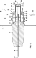
- the Figure 1a shows a cross section along the longitudinal axis LA of the exhaust gas sensor 1 according to a first exemplary embodiment.
- the exhaust gas sensor 1 has a sleeve-shaped sensor housing 12, in whose through hole a ceramic sensor element 14 is fixed.
- the ceramic sensor element 14 projects both on the side of the sensor housing 12 facing the exhaust gas (in Figure 1a right) as well as on the side of the sensor housing 12 facing away from the exhaust gas (in Figure 1a left) beyond sensor housing 12.
- a sleeve-shaped, metallic protective tube 20 is welded to a circumferential collar 121 of the sensor housing 12 pointing in the exhaust gas direction.
- the protective tube 20 consists of an inner protective sleeve 21 and an outer protective sleeve 22.
- the inner protective sleeve 21 surrounds an exhaust-side end region 141 of the sensor element 14 with a radial and axial distance.
- the outer protective sleeve 22 surrounds the inner protective sleeve 21 in such a way that it rests on the inner protective tube 21 at the axial height of the collar 121 and is welded together with this to the collar 121 by means of a circumferential weld seam, and also on the exhaust side of the collar 121 between the outer protective sleeve 22 and inner protective sleeve 21 an annular space 30 is formed, that a contact area 31 is also formed on the exhaust side of the annular space 30, in which the inner protective sleeve 21 with its outer surface fully rests on the inner surface of the outer protective sleeve 22 and that furthermore on the exhaust side of the contact area 31 End space 32 is formed, which is delimited radially by the outer protective sleeve 22, is delimited on the side facing away from the exhaust gas by a bottom 211 of the inner protective sleeve 21 designed as a baffle plate and delimited on the side facing the exhaust gas by a bottom 221 of the outer protective slee
- the outer protective sleeve 22 has, for example, eight gas inlet openings 222, which are arranged at equal distances along the circumference of the outer protective sleeve 22 at the axial height of an end region 301 of the annular space 30 facing the exhaust gas.
- the gas inlet openings 222 each have a swirl element 223, which is designed as a swirl flap and gives the gas flowing into the annular space 30 an impulse directed towards the sensor housing 12 and an angular momentum directed in the direction of the longitudinal axis LA of the sensor, so that the exhaust gas within the annular space 30 rotates around the inner protective sleeve 21.
- swirl elements 223 can be dispensed with.
- the outer protective sleeve 22 also has a relatively large one on the bottom 221 Gas outlet opening 224.
- the gas outlet opening 224 can even be enlarged in such a way that the bottom 221 is completely or largely eliminated.
- the inner protective sleeve 21 has, for example, 32 comparatively small gas inlet openings 212, which are arranged at equal distances along the circumference of the inner protective sleeve 21 in two rows at the axial height of an approximately central region 302 of the annular space 30 in the axial direction.
- the gas inlet openings 212 are also arranged at the axial height of the sensor element 14.
- the gas inlet openings 212 are arranged at the axial height of a sensitive area of the sensor element 14.
- the sensitive area of the sensor element 14 is, for example, an interdigital electrode structure 142 (see also Fig. 1b ), in this respect the exhaust gas sensor is a particle sensor for detecting soot in the exhaust gas of an internal combustion engine.
- the sensitive area could also be an electrode of an electrochemical cell and/or an opening leading into the interior of the sensor element, for example of a broadband lambda probe or a NOx sensor.
- the inner protective sleeve 21 has a ring of eight off-center gas outlet openings 213 on its base 211.
- a further central gas outlet opening 213 is provided on the bottom 211 of the inner protective sleeve 21. In one variant, the latter can also be omitted.
- the 32 gas inlet openings 212 of the inner protective sleeve 21 are circular in the example and have a diameter of 0.5mm.
- the flow cross section of the gas inlet of the inner protective sleeve is therefore 6mm 2 .
- the flow cross section of the gas outlet of the inner protective sleeve 21 is 10mm 2 in the example.
- the flow cross section of the gas outlet of the outer protective sleeve 22 is 14mm 2 in the example.
- the flow cross section of the gas inlet of the outer protective sleeve 22 is 10mm 2 in the example.
- the length of the sensor element 14 is approximately 55mm, the longitudinal extent of the protective tube 20 is approximately 28mm.
- the gas inlet of the inner protective sleeve 21 thus forms the smallest flow cross section when flowing through the protective tube 20, which results in the positive effects explained at the beginning.
- the diameter of the gas inlet openings 212 of the inner protective sleeve 21 can be reduced to 0.4mm or even to 0.3mm. In alternatives to this, only eight, in particular circular, gas inlet openings 212 of the inner protective sleeve 21 can be provided, the diameter of which is 1 mm or 0.8 mm or 0.6 mm and which are arranged in a row evenly along the circumference of the inner protective tube 21.
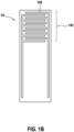
- the Figure 1b shows a top view of the sensor element 14 in the perspective from bottom to top in the Figure 1a .
- the sensor element 14 is designed to be planar and an interdigital electrode structure 142 is arranged on the surface of the sensor element 14 in an exhaust-side end region 141, which forms the sensitive region of the sensor element 14.
- the exhaust gas sensor 1 can be mounted in the wall 51 of an exhaust pipe 50 of an internal combustion engine in such a way that, as seen in a cross section of the exhaust pipe 50, the gas inlet of the outer protective sleeve 22 is arranged in an edge region 52 of the exhaust pipe, while the gas outlet of the outer protective sleeve 22 is in a central one Area 53 of the exhaust pipe is arranged, see Figure 1a .
- Exhaust gas flows through the exhaust pipe 50 essentially perpendicular to the longitudinal axis LA of the exhaust gas sensor 1, parallel to the plane of the drawing Figure 1a , in the direction of the double arrow 100.
- the exhaust gas then passes through the gas outlet openings 213 of the inner protective sleeve 21 into the end space 32 and from there through the gas outlet opening 224 of the outer protective sleeve 22.
- This flow is in the Figure 1a indicated by arrow line 101.
- the Figure 2 shows a cross section along the longitudinal axis LA of the exhaust gas sensor 1 according to a second exemplary embodiment.
- the exhaust gas sensor 1 has a sleeve-shaped sensor housing 12, in whose through hole a ceramic sensor element 14 is fixed.
- the ceramic sensor element 14 projects both on the side of the sensor housing 12 facing the exhaust gas (in Figure 2 right) as well as on the side of the sensor housing 12 facing away from the exhaust gas (in Figure 2 left) beyond the sensor housing 12.
- a sleeve-shaped, metallic protective tube 20 is welded to a circumferential collar 121 of the sensor housing 12 pointing in the exhaust gas direction.
- the protective tube 20 consists of an inner protective sleeve 21 and an outer protective sleeve 22.
- the inner protective sleeve 21 surrounds an exhaust-side end region 141 of the sensor element 14 with a radial and axial distance.
- the outer protective sleeve 22 surrounds the inner protective sleeve 21 in such a way that it rests on the inner protective tube 21 at the axial height of the collar 121 and is welded together with this to the collar 121 by means of a circumferential weld and that furthermore on the exhaust side of the collar 121 between the outer protective sleeve 22 and inner protective sleeve 21 an annular space 30 is formed.
- the outer protective sleeve 22 On the exhaust side of the annular space 30, the outer protective sleeve 22 has a relatively large central gas outlet opening 224, in which the inner protective sleeve 21 is fixed and through which the inner protective sleeve 21 protrudes on the exhaust side over the outer protective sleeve 22 in a projection area 33.
- the inner protective sleeve 21 is fixed, in particular pressed, in the gas outlet opening 224 of the outer protective sleeve 22 without any gaps, i.e. tightly.
- the projection area 33 ends on the exhaust side with a base 211 of the inner protective sleeve 21.
- the outer protective sleeve 22 has, for example, eight gas inlet openings 222, which are arranged at equal distances along the circumference of the outer protective sleeve 22 at the axial height of an end region 301 of the annular space 30 facing the exhaust gas.
- the gas inlet openings 222 each have a swirl element 223, which acts as a swirl flap is designed and gives the gas flowing into the annular space 30 an impulse directed towards the sensor housing 12 and an angular momentum directed in the direction of the longitudinal axis LA of the sensor, so that the exhaust gas rotates within the annular space 30 around the inner protective sleeve 21.
- swirl elements 223 can be dispensed with.
- the inner protective sleeve 21 has, for example, 32 comparatively small gas inlet openings 212, which are arranged at equal distances along the circumference of the inner protective sleeve 21 in two rows at the axial height of an approximately central region 302 of the annular space 30 in the axial direction.
- the gas inlet openings 212 are also arranged at the axial height of the sensor element 14.
- the gas inlet openings 212 are arranged at the axial height of a sensitive area of the sensor element 14.
- the sensitive area of the sensor element 14 is, for example, an interdigital electrode structure 142 (see also Fig. 1b ), in this respect the exhaust gas sensor is a particle sensor for detecting soot in the exhaust gas of an internal combustion engine.
- the sensitive area could also be an electrode of an electrochemical cell and/or an opening leading into the interior of the sensor element, for example of a broadband lambda probe or a NOx sensor.
- the inner protective sleeve 21 has a central, relatively large gas outlet opening 213 on its base 211.
- the gas inlet openings 212 of the inner protective sleeve 21 are circular in the example and have a diameter of 0.5mm.
- the flow cross section of the gas inlet of the inner protective sleeve 21 is therefore 6mm 2 .
- the flow cross section of the gas outlet of the inner protective sleeve 21 is 14mm 2 in the example.
- the flow cross section of the gas inlet of the outer protective sleeve 22 is 10mm 2 in the example.
- the length of the sensor element 14 is approximately 55mm, the longitudinal extent of the protective tube 20 is approximately 28mm.
- the gas inlet of the inner protective sleeve 21 thus forms the smallest flow cross section when flowing through the protective tube 20, from which the The positive effects explained at the beginning result.
- the diameter of the gas inlet openings 212 of the inner protective sleeve 21 can be reduced to 0.4mm or even to 0.3mm.
- only eight, in particular circular, gas inlet openings 212 of the inner protective sleeve 21 can be provided, the diameter of which is 1mm or 0.8mm or 0.6mm and which are arranged in a row evenly along the circumference of the inner protective tube 21.
- a top view of the sensor element 14 in the perspective from bottom to top in the Figure 2 is as in Figure 1b shown.
- the sensor element 14 is designed to be planar and an interdigital electrode structure 142 is arranged on the surface of the sensor element 14 in an exhaust-side end region 141, which forms the sensitive region of the sensor element 14.
- a cylindrical sensor element 14 can also be used.
- the exhaust gas sensor 1 can be mounted in the wall 51 of an exhaust pipe 50 of an internal combustion engine in such a way that, seen in a cross section of the exhaust pipe 50, the gas inlet of the outer protective sleeve 22 is arranged in an edge region 52 of the exhaust pipe, while the gas outlet of the inner protective sleeve 21 is in a central one Area 53 of the exhaust pipe is arranged, see Figure 2 .
- Exhaust gas flows through the exhaust pipe 50 essentially perpendicular to the longitudinal axis LA of the exhaust gas sensor 1, parallel to the plane of the drawing Figure 2 , in the direction of the double arrow 100.
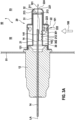
- the Figure 3 shows a cross section along the longitudinal axis LA of the exhaust gas sensor 1 according to a third exemplary embodiment.
- the exhaust gas sensor 1 has a sleeve-shaped sensor housing 12, in whose through hole a ceramic sensor element 14 is fixed.
- the ceramic sensor element 14 projects both on the side of the sensor housing 12 facing the exhaust gas (in Figure 3 right) as well as on the side of the sensor housing 12 facing away from the exhaust gas (in Figure 3 left) beyond the sensor housing 12.
- a sleeve-shaped, metallic protective tube 20 is welded to a circumferential collar 121 of the sensor housing 12 pointing in the exhaust gas direction.
- the protective tube 20 consists of an inner protective sleeve 21 and an outer protective sleeve 22.
- the inner protective sleeve 21 surrounds an exhaust-side end region 141 of the sensor element 14 with a radial and axial distance.
- the outer protective sleeve 22 surrounds the inner protective sleeve 21 in such a way that it rests on the inner protective tube 21 at the axial height of the collar 121 and is welded together with this to the collar 121 by means of a circumferential weld seam, and also on the exhaust side of the collar 121 between the outer protective sleeve 22 and inner protective sleeve 21 an annular space 30 is formed, that a contact area 31 is also formed on the exhaust side of the annular space 30, in which the inner protective sleeve 21 with its outer surface fully rests on the inner surface of the outer protective sleeve 22 and that furthermore on the exhaust side of the contact area 31 End space 32 is formed, which is delimited radially by the outer protective sleeve 22, is delimited on the side facing away from the exhaust gas by a bottom 211 of the inner protective sleeve 21 designed as a baffle plate and delimited on the side facing the exhaust gas by a bottom 221 of the outer protective slee
- the outer protective sleeve 22 has, for example, eight gas inlet openings 222, which are arranged at equal distances along the circumference of the outer protective sleeve 22 at the axial height of an end region 301 of the annular space 30 facing the exhaust gas.
- the gas inlet openings 222 each have a swirl element 223, which acts as a swirl flap is designed and gives the gas flowing into the annular space 30 an impulse directed towards the sensor housing 12 and an angular momentum directed in the direction of the longitudinal axis LA of the sensor, so that the exhaust gas rotates within the annular space 30 around the inner protective sleeve 21.
- swirl elements 223 can be dispensed with.
- the outer protective sleeve 22 also has a relatively large gas outlet opening 224 on the base 221.
- the gas outlet opening 224 can even be enlarged in such a way that the bottom 221 is completely or largely eliminated.
- the inner protective sleeve 21 points in the in Figure 3 Lower area has eight gas inlet openings 212, which run in two rows of four gas inlet openings 212 each running next to one another in the axial direction.
- the gas inlet openings 212 are arranged at the axial height of an approximately central region 302 of the annular space 30 in the axial direction.
- the gas inlet openings 212 are also arranged at the axial height of the sensor element 14. In one variant, only four gas inlet openings 212 are provided, which run in two rows next to each other in the axial direction, each with two gas inlet openings 212.
- the gas inlet openings 212 are arranged at the axial height of a sensitive area of the sensor element 14.
- the sensitive area of the sensor element 14 is, for example, an interdigital electrode structure 142 (see also Fig. 1b ), in this respect the exhaust gas sensor is a particle sensor for detecting soot in the exhaust gas of an internal combustion engine.
- the sensitive area could also be an electrode of an electrochemical cell and/or an opening leading into the interior of the sensor element, for example of a broadband lambda probe or a NOx sensor.
- a special feature of the exemplary embodiment is that all gas inlet openings 212 of the inner protective sleeve 21 are arranged only on a radial partial area and only on an axial partial area of the inner protective sleeve 21 and the sensitive area and all gas inlet openings 212 of the inner protective sleeve 21 are arranged on one another are opposite, so that exhaust gas entering the interior of the inner protective sleeve 21 always flows directly into the sensitive area.
- the inner protective sleeve 21 has a ring of eight off-center gas outlet openings 213 on its base 211.
- a further central gas outlet opening 213 is provided on the bottom 211 of the inner protective sleeve 21.
- this central gas outlet opening 213 can also be omitted.
- the gas outlet openings 213 of the inner protective sleeve 21 are circular, in particular with the exception of the gas outlet opening 213*, which is in the Figure 3a pointing downwards.
- the latter is designed as an oval hole or elongated hole and thus indicates the position of the gas inlet openings 212 of the inner protective sleeve 21 to the outside in such a way that it can be visually recognized when looking along the longitudinal axis LA of the sensor, see Figure 3b .
- the gas inlet openings 212 of the inner protective sleeve 21 are circular in the example and have a diameter of 1mm.
- the flow cross section of the gas inlet of the inner protective sleeve 21 is therefore 6mm 2 .
- the flow cross section of the gas outlet of the inner protective sleeve 21 is 10mm 2 in the example.
- the flow cross section of the gas outlet of the outer protective sleeve 22 is 14mm 2 in the example.
- the flow cross section of the gas inlet of the outer protective sleeve 22 is 10mm 2 in the example.
- the length of the sensor element 14 is approximately 55mm, the longitudinal extent of the protective tube 20 is approximately 28mm.
- the gas inlet of the inner protective sleeve 21 thus forms the smallest flow cross section when flowing through the protective tube 20, which results in the positive effects explained at the beginning.
- the diameter of the gas inlet openings 212 of the inner protective sleeve 21 can be reduced to 0.8mm or even to 0.6mm or even further.
- a top view of the sensor element 14 in the perspective from bottom to top in the Figure 3 is like in the Figure 1b shown.
- the sensor element 14 is planar and on the surface of the sensor element 14 there is an interdigital electrode structure 142 in an exhaust-side end region 141 arranged, which forms the sensitive area of the sensor element 14.
- the exhaust gas sensor 1 can be mounted in the wall 51 of an exhaust pipe 50 of an internal combustion engine in such a way that, as seen in a cross section of the exhaust pipe 50, the gas inlet of the outer protective sleeve 22 is arranged in an edge region 52 of the exhaust pipe, while the gas outlet of the outer protective sleeve 22 is in a central one Area 53 of the exhaust pipe is arranged, see Figure 3 .
- Exhaust gas flows through the exhaust pipe 50 essentially perpendicular to the longitudinal axis LA of the exhaust gas sensor 1, parallel to the plane of the drawing Figure 3 , in the direction of the double arrow 100.
- the Figure 4 shows a cross section along the longitudinal axis LA of the exhaust gas sensor 1 according to a fourth exemplary embodiment.
- the exhaust gas sensor 1 has a sleeve-shaped sensor housing 12, in whose through hole a ceramic sensor element 14 is fixed.
- the ceramic sensor element 14 projects both on the side of the sensor housing 12 facing the exhaust gas (in Figure 4 right) as well as on the side of the sensor housing 12 facing away from the exhaust gas (in Figure 4 left) beyond the sensor housing 12.
- the protective tube 20 consists of an inner protective sleeve 21 and an outer protective sleeve 22.
- the inner protective sleeve 21 surrounds an exhaust-side end region 141 of the sensor element 14 with a radial and axial distance.
- the outer protective sleeve 22 surrounds the inner protective sleeve 21 in such a way that it rests on the inner protective tube 21 at the axial height of the collar 121 and is welded together with this to the collar 121 by means of a circumferential weld and that furthermore on the exhaust side of the collar 121 between the outer protective sleeve 22 and inner protective sleeve 21 an annular space 30 is formed.
- the outer protective sleeve 22 On the exhaust side of the annular space 30, the outer protective sleeve 22 has a relatively large central gas outlet opening 224, in which the inner protective sleeve 21 is fixed and through which the inner protective sleeve 21 protrudes on the exhaust side over the outer protective sleeve 22 in a projection area 33.
- the inner protective sleeve 21 is fixed, in particular pressed, in the gas outlet opening 224 of the outer protective sleeve 22 without any gaps, i.e. tightly.
- the projection area 33 ends on the exhaust side with a base 211 of the inner protective sleeve 21.
- the outer protective sleeve 22 has, for example, eight gas inlet openings 222, which are arranged at equal distances along the circumference of the outer protective sleeve 22 at the axial height of an end region 301 of the annular space 30 facing the exhaust gas.
- the gas inlet openings 222 each have a swirl element 223, which is designed as a swirl flap and gives the gas flowing into the annular space 30 an impulse directed towards the sensor housing 12 and an angular momentum directed in the direction of the longitudinal axis LA of the sensor, so that the exhaust gas within the annular space 30 rotates around the inner protective sleeve 21.
- swirl elements 223 can be dispensed with.
- the inner protective sleeve 21 points in the in Figure 4 Lower area has eight gas inlet openings 212, which run in two rows of four gas inlet openings 212 each running next to one another in the axial direction.
- the gas inlet openings 212 are arranged at the axial height of an approximately central region 302 of the annular space 30 in the axial direction.
- the Gas inlet openings 212 are also arranged at the axial height of the sensor element 14. In one variant, only four gas inlet openings 212 are provided, which run in two rows next to each other in the axial direction, each with two gas inlet openings 212.
- the gas inlet openings 212 are arranged at the axial height of a sensitive area of the sensor element 14.
- the sensitive area of the sensor element 14 is, for example, an interdigital electrode structure 142 (see also Fig. 1b ), in this respect the exhaust gas sensor is a particle sensor for detecting soot in the exhaust gas of an internal combustion engine.
- the sensitive area could also be an electrode of an electrochemical cell and/or an opening leading into the interior of the sensor element, for example of a broadband lambda probe or a NOx sensor.
- a special feature of the exemplary embodiment is that all gas inlet openings 212 of the inner protective sleeve 21 are arranged only on a radial partial area and only on an axial partial area of the inner protective sleeve 21 and the sensitive area and all gas inlet openings 212 of the inner protective sleeve 21 are opposite one another, so that in The exhaust gas entering the interior of the inner protective sleeve 21 always flows directly into the sensitive area.
- the inner protective sleeve 21 has a central, relatively large gas outlet opening 213 on its base 211.
- the gas inlet openings 212 of the inner protective sleeve 21 are circular in the example and have a diameter of 1mm.
- the flow cross section of the gas inlet of the inner protective sleeve 21 is therefore 6mm 2 .
- the flow cross section of the gas outlet of the inner protective sleeve 21 is 14mm 2 in the example.
- the flow cross section of the gas inlet of the outer protective sleeve 22 is 10mm 2 in the example.
- the length of the sensor element 14 is approximately 55mm, the longitudinal extent of the protective tube 20 is approximately 28mm.
- the gas inlet of the inner protective sleeve 21 thus forms the smallest flow cross section when flowing through the protective tube 20, which results in the positive effects explained at the beginning.
- the diameter of the gas inlet openings 212 of the inner protective sleeve 21 can be reduced to 0.8mm or even to 0.6mm or even further.
- a top view of the sensor element 14 in the perspective from bottom to top in the Figure 4 is as in Figure 1b shown.
- the sensor element 14 is designed to be planar and an interdigital electrode structure 142 is arranged on the surface of the sensor element 14 in an exhaust-side end region 141, which forms the sensitive region of the sensor element 14.
- the exhaust gas sensor 1 can be mounted in the wall 51 of an exhaust pipe 50 of an internal combustion engine in such a way that, seen in a cross section of the exhaust pipe 50, the gas inlet of the outer protective sleeve 22 is arranged in an edge region 52 of the exhaust pipe, while the gas outlet of the inner protective sleeve 21 is in a central one Area 53 of the exhaust pipe is arranged, see Figure 4 .
- Exhaust gas flows through the exhaust pipe 50 essentially perpendicular to the longitudinal axis LA of the exhaust gas sensor 1, parallel to the plane of the drawing Figure 4 , in the direction of the double arrow 100.
- the Figure 5 shows a cross section along the longitudinal axis LA of the exhaust gas sensor 1 according to a fifth exemplary embodiment.
- the exhaust gas sensor 1 has a sleeve-shaped sensor housing 12, in the through hole of which ceramic sensor element 14 is fixed.
- the ceramic sensor element 14 projects both on the side of the sensor housing 12 facing the exhaust gas (in Figure 5 right) as well as on the side of the sensor housing 12 facing away from the exhaust gas (in Figure 5 left) beyond the sensor housing 12.
- a sleeve-shaped, metallic protective tube 20 is welded to a circumferential collar 121 of the sensor housing 12 pointing in the exhaust gas direction.
- the protective tube 20 consists of an inner protective sleeve 21 and an outer protective sleeve 22.
- the inner protective sleeve 21 surrounds an exhaust-side end region 141 of the sensor element 14 with a radial and axial distance.
- the outer protective sleeve 22 surrounds the inner protective sleeve 21 in such a way that it rests on the inner protective tube 21 at the axial height of the collar 121 and is welded together with this to the collar 121 by means of a circumferential weld seam, and also on the exhaust side of the collar 121 between the outer protective sleeve 22 and inner protective sleeve 21 an annular space 30 is formed, that a contact area 31 is also formed on the exhaust side of the annular space 30, in which the inner protective sleeve 21 with its outer surface fully rests on the inner surface of the outer protective sleeve 22 and that furthermore on the exhaust side of the contact area 31 End space 32 is formed, which is delimited radially by a region of the outer protective sleeve 22 which is slightly radially tapered by means of an annular shoulder 226, is open towards the interior of the inner protective sleeve 21 on the side facing away from the exhaust gas and by a base 221 on the side facing the exhaust gas
- the outer protective sleeve 22 has, for example, eight gas inlet openings 222, which are arranged at equal distances along the circumference of the outer protective sleeve 22 at the axial height of an end region 301 of the annular space 30 facing the exhaust gas.
- the gas inlet openings 222 each have a swirl element 223, which is designed as a swirl flap and gives the gas flowing into the annular space 30 an impulse directed towards the sensor housing 12 and an angular momentum directed in the direction of the longitudinal axis LA of the sensor, so that the exhaust gas within the annular space 30 rotates around the inner protective sleeve 21.
- swirl elements 223 can be dispensed with.
- the outer protective sleeve 22 also has a relatively large gas outlet opening 224 on the base 221.
- the gas outlet opening 224 can even be enlarged in such a way that the bottom 221 is completely or largely eliminated.
- the inner protective sleeve 21 has, for example, eight gas inlet openings 212, which are arranged at equal distances along the circumference of the inner protective sleeve 21 on the housing side at the axial height of a region 303 of the annular space 30 on the housing side in the axial direction.
- the gas inlet openings 212 are also arranged at the axial height of the sensor element 14.
- the gas inlet openings 212 are arranged on the housing side of a sensitive area of the sensor element 14.
- the sensitive area of the sensor element 14 is an interdigital electrode structure 142 (see also Fig. 1b ), in this respect the exhaust gas sensor is a particle sensor for detecting soot in the exhaust gas of an internal combustion engine.
- the gas inlet openings 212 are in particular rectangular and in particular each have a particularly rectangular deflection element 215, which is in particular in the form of a strip pressed into the sensor housing 12 and which is an exhaust gas entering the annular space 30 deflects in the direction of the gas outlet of the inner protective sleeve 21.
- the gas inlet opening 212 can also be assigned a deflection element 215, which has a different shape, in particular the shape of the swirl flap, and which deflects an exhaust gas entering the annular space 30 in the direction of the gas outlet of the inner protective sleeve 21.
- the gas inlet openings 212 of the inner protective sleeve 21 are in this Example arranged on the axial side of the sensitive area of the sensor element 14 facing away from the exhaust gas.
- the exhaust gas flowing into the interior of the inner protective sleeve 21 is directed by the deflection elements 215 onto the sensitive area of the sensor element 14.
- the inner protective sleeve 21 can have a ring of eight off-center gas outlet openings 213 on its base 211.
- a further central gas outlet opening 213 can be provided on the bottom 211 of the inner protective sleeve.
- the gas inlet openings 212 of the inner protective sleeve 21 are rectangular in the example and have a total flow cross section of 8mm 2 .
- the flow cross section of the gas outlet of the inner protective sleeve 21 is over 50mm 2 in the example.
- the flow cross section of the gas outlet of the outer protective sleeve 22 is 14mm 2 in the example.
- the flow cross section of the gas inlet of the outer protective sleeve 22 is 10mm 2 in the example.
- the length of the sensor element 14 is approximately 55mm, the longitudinal extent of the protective tube 20 is approximately 28mm.
- the gas inlet of the inner protective sleeve 21 thus forms the smallest flow cross section when flowing through the protective tube 20, which results in the positive effects explained at the beginning.
- the cross section of the gas inlet openings 212 of the inner protective sleeve 21 can be reduced to 0.8 or even 0.6mm 2 each.
- a top view of the sensor element 14 in the perspective from bottom to top in the Figure 5 is as in Figure 1b shown.
- the sensor element 14 is designed to be planar and an interdigital electrode structure 142 is arranged on the surface of the sensor element 14 in an exhaust-side end region 141, which forms the sensitive region of the sensor element 14.
- a cylindrical sensor element 14 can also be used.
- the exhaust gas sensor 1 can be mounted in the wall 51 of an exhaust pipe 50 of an internal combustion engine in such a way that, as seen in a cross section of the exhaust pipe 50, the gas inlet of the outer protective sleeve 22 is arranged in an edge region 52 of the exhaust pipe, while the gas outlet of the outer protective sleeve 22 is in a central one Area 53 of the exhaust pipe is arranged, see Figure 5 .
- Exhaust gas flows through the exhaust pipe 50 essentially perpendicular to the longitudinal axis LA of the exhaust gas sensor 1, parallel to the plane of the drawing Figure 5 , in the direction of the double arrow 100.
- the Figure 6 shows a cross section along the longitudinal axis LA of the exhaust gas sensor 1 according to a sixth exemplary embodiment.
- the exhaust gas sensor 1 has a sleeve-shaped sensor housing 12, in whose through hole a ceramic sensor element 14 is fixed.
- the ceramic sensor element 14 projects both on the side of the sensor housing 12 facing the exhaust gas (in Figure 6 right) as well as on the side of the sensor housing 12 facing away from the exhaust gas (in Figure 6 left) beyond the sensor housing 12.
- a sleeve-shaped, metallic protective tube 20 is welded to a circumferential collar 121 of the sensor housing 12 pointing in the exhaust gas direction.
- the protective tube 20 consists of an inner protective sleeve 21 and an outer protective sleeve 22.
- the inner protective sleeve 21 surrounds an exhaust-side end region 141 of the sensor element 14 with a radial and axial distance.
- the outer protective sleeve 22 surrounds the inner protective sleeve 21 in such a way that it rests on the inner protective tube 21 at the axial height of the collar 121 and is welded together with this to the collar 121 by means of a circumferential weld and that furthermore on the exhaust side of the collar 121 between the outer protective sleeve 22 and inner protective sleeve 21 an annular space 30 is formed.
- the outer protective sleeve 22 On the exhaust side of the annular space 30, the outer protective sleeve 22 has a relatively large central gas outlet opening 224, in which the inner protective sleeve 21 is fixed and through which the inner protective sleeve 21 protrudes on the exhaust side over the outer protective sleeve 22 in a projection area 33.
- the inner protective sleeve 21 is fixed, in particular pressed, in the gas outlet opening 224 of the outer protective sleeve 22 without any gaps, i.e. tightly.
- the projection area 33 ends on the exhaust side with a base 211 of the inner protective sleeve 21.
- the outer protective sleeve 22 has, for example, eight gas inlet openings 222, which are arranged at equal distances along the circumference of the outer protective sleeve 22 at the axial height of an end region 301 of the annular space 30 facing the exhaust gas.
- the gas inlet openings 222 each have a swirl element 223, which is designed as a swirl flap and gives the gas flowing into the annular space 30 an impulse directed towards the sensor housing 12 and an angular momentum directed in the direction of the longitudinal axis LA of the sensor, so that the exhaust gas within the annular space 30 rotates around the inner protective sleeve 21.
- swirl elements 223 can be dispensed with.
- the inner protective sleeve 21 has, for example, eight gas inlet openings 212, which are arranged at equal distances along the circumference of the inner protective sleeve 21 in a region 303 of the annular space 30 on the housing side in the axial direction.
- the gas inlet openings 212 are also arranged at the axial height of the sensor element 14.
- the gas inlet openings 212 are arranged on the housing side of a sensitive area of the sensor element 14.
- the sensitive area of the sensor element 14 is an interdigital electrode structure 142 (see also Fig. 1b ), in this respect the exhaust gas sensor is a particle sensor for detecting soot in the exhaust gas of an internal combustion engine.
- the gas inlet openings 212 are in particular rectangular and in particular each have a particularly rectangular deflection element 215, which is in particular in the form of a strip pressed into the sensor housing 12 and which is an exhaust gas entering the annular space 30 deflects in the direction of the gas outlet of the inner protective sleeve 21.
- the gas inlet opening 212 can also be assigned a deflection element 215, which has a different shape, in particular the shape of the swirl flap, and which deflects an exhaust gas entering the annular space 30 in the direction of the gas outlet of the inner protective sleeve 21.
- the gas inlet openings 212 of the inner protective sleeve 21 are arranged on the axial side of the sensitive area of the sensor element 14 facing away from the exhaust gas.
- the exhaust gas flowing into the interior of the inner protective sleeve 21 is directed by the deflection elements 215 onto the sensitive area of the sensor element 14.
- the inner protective sleeve 21 has a central, relatively large gas outlet opening 213 on its base 211.
- the gas inlet openings 212 of the inner protective sleeve 21 are rectangular in the example and have a total flow cross section of 8mm 2 .
- the flow cross section of the gas outlet of the inner protective sleeve 21 is over 14mm 2 in the example.
- the flow cross section of the gas inlet of the outer protective sleeve 22 is 10mm 2 in the example.
- the length of the sensor element 14 is approximately 55mm, the longitudinal extent of the protective tube 20 is approximately 28mm.
- the gas inlet of the inner protective sleeve 21 thus forms the smallest flow cross section when flowing through the protective tube 20, which results in the positive effects explained at the beginning.
- the cross section of the gas inlet openings 212 of the inner protective sleeve 21 can be reduced to 0.8 or even 0.6mm 2 each.
- a top view of the sensor element 14 in the perspective from bottom to top in the Figure 6 is as in Figure 1b shown.
- the sensor element 14 is designed to be planar and an interdigital electrode structure 142 is arranged on the surface of the sensor element 14 in an exhaust-side end region 141, which forms the sensitive region of the sensor element 14.
- the exhaust gas sensor 1 can be mounted in the wall 51 of an exhaust pipe 50 of an internal combustion engine in such a way that, seen in a cross section of the exhaust pipe 50, the gas inlet of the outer protective sleeve 22 is arranged in an edge region 52 of the exhaust pipe, while the gas outlet of the inner protective sleeve 21 is in a central one Area 53 of the exhaust pipe is arranged, see Figure 6 .
- Exhaust gas flows through the exhaust pipe 50 essentially perpendicular to the longitudinal axis LA of the exhaust gas sensor 1, parallel to the plane of the drawing Figure 6 , in the direction of the double arrow 100.
Landscapes
- Chemical & Material Sciences (AREA)
- Health & Medical Sciences (AREA)
- Life Sciences & Earth Sciences (AREA)
- General Physics & Mathematics (AREA)
- Pathology (AREA)
- Analytical Chemistry (AREA)
- Biochemistry (AREA)
- General Health & Medical Sciences (AREA)
- Physics & Mathematics (AREA)
- Immunology (AREA)
- Dispersion Chemistry (AREA)
- Chemical Kinetics & Catalysis (AREA)
- Electrochemistry (AREA)
- Engineering & Computer Science (AREA)
- Molecular Biology (AREA)
- Combustion & Propulsion (AREA)
- Mechanical Engineering (AREA)
- General Engineering & Computer Science (AREA)
- Measuring Oxygen Concentration In Cells (AREA)
Description
- Beispielsweise aus der
DE 40 34 072 A1 ist ein Abgassensor bekannt, der ein hülsenförmiges Sensorgehäuse, ein in dem Sensorgehäuse fixiertes Sensorelement, das abgasseitig über das Sensorgehäuse hinausragt, und ein hülsenförmiges Schutzrohr, das abgasseitig auf dem Sensorgehäuse befestigt ist, umfasst, wobei das Schutzrohr aus einer inneren Schutzhülse und einer äußeren Schutzhülse besteht, wobei die innere Schutzhülse einen abgasseitigen Endbereich des Sensorelements umgibt, wobei die äußere Schutzhülse die innere Schutzhülse zumindest bereichsweise umgibt, sodass zwischen äußerer Schutzhülse und innerer Schutzhülse ein ringförmiger Raum ausgebildet ist, wobei die äußere Schutzhülse und die innere Schutzhülse jeweils einen Gasaustritt und einen Gaseintritt aufweisen und eine Durchströmung des Schutzrohrs von dem Gaseintritt der äußeren Schutzhülse in den ringförmigen Raum, von dort durch den Gaseintritt der inneren Schutzhülse in das Innere der inneren Schutzhülse und von dort durch die Gasaustritte der äußeren und der inneren Schutzhülse erfolgt. - Die
DE 10 2016 102 597 A1 offenbart ein System zur Erkennung von Feinstaub in einem Abgassystem eines Fahrzeuges umfassend ein erstes äußeres Rohr mit einer Vielzahl von Ansaugöffnungen auf einer stromaufwärtigen Oberfläche und ein zweites inneres Rohr mit einer Vielzahl von Ansaugöffnungen auf einer stromabwärtigen Oberfläche, und einen Feinstaubpartikel-Sensor, der innerhalb des zweiten inneren Rohrs positioniert ist. - Die vorliegende Erfindung betrifft einen Abgassensor wie in Anspruch 1 definiert. Bevorzugte Merkmale des Abgassensors sind in den abhängigen Ansprüchen beschrieben. Eine Verwendung des Abgassensors ist in Anspruch 10 definiert. Es handelt sich hierbei um einen Partikelsensor zum Nachweis der Konzentration fester Bestandteile eines Gases, beispielsweise der Konzentration von Ruß in einem Abgas einer Brennkraftmaschine.
- Mit Hinblick auf Abgassensoren im Allgemeinen basiert die vorliegende Erfindung auf der Erkenntnis, dass die Sensitivität und Dynamik des Abgassensors grundsätzlich von seiner Orientierung in einer Abgasleitung beeinflusst wird, insbesondere hinsichtlich der Verdrehung des Abgassensors um seine Längsachse, welche vorzugsweise senkrecht zur Hauptströmungsrichtung in der Abgasleitung ausgerichtet ist. Es wurde erkannt, dass beispielsweise bei dem aus dem Stand der Technik bekannten Abgassensor Abgas bevorzugt durch die stromaufwärts angeordneten Gaseintrittsöffnungen der inneren und der äußere Schutzhülse in das Innere des Schutzrohrs eintritt und das Sensorelement bevorzugt von diesen Gaseintrittsöffnungen aus gerichtet anströmt. Bei anderen bereits bekannte Sensoren kann es auch zu dem gegenteiligen Effekt kommen, dass Abgas bevorzugt durch die stromabwärts angeordneten Gaseintrittsöffnungen der inneren und der äußere Schutzhülse in das Innere des Schutzrohrs eintritt und das Sensorelement bevorzugt von diesen Gaseintrittsöffnungen aus gerichtet anströmt. In beiden Fällen resultiert je nach Orientierung des Sensorelements relativ zu den stromaufwärts/ bzw. stromabwärts angeordneten Gaseintrittsöffnungen daher bei diesen Sensoren eine unterschiedliche Sensitivität und Dynamik des Abgassensors.
- In einem weiteren Schritt wurde erkannt, dass eine ausreichende Drosselwirkung des Gaseintritts der inneren Schutzhülse, die gewährleistet ist, wenn der Gaseintritt der inneren Schutzhülse den kleinsten Strömungsquerschnitt bei der Durchströmung des Schutzrohrs bildet, zu einem relativen Unterdruck im Inneren der inneren Schutzhülse führt. Durch den sich vor dem Gaseintritts der inneren Schutzhülse ausbildenden Rückstau des Abgases homogenisiert sich die Abgasströmung im Ringraum und im Inneren der inneren Schutzhülse. Das Abgas wird durch den Gaseintritt der inneren Schutzhülse in das Innere der inneren Schutzhülse aufgrund des dort vorherrschenden Unterdrucks homogen eingesaugt. Eine Beeinflussung der Sensitivität und der Dynamik des Abgassensors von seiner Orientierung in einer Abgasleitung geht somit verloren, insbesondere erfolgt ein Einströmen des Abgases in das Innere der inneren Schutzhülse weitgehend unabhängig von einer Verdrehung des Abgassensors um seine Längsachse.
- Die Genauigkeit des Abgassensors bei undefinierter orientierter Montage in einer Abgasleitung, insbesondere bei undefinierter Verdrehung des Abgassensors um seine Längsachse, ist auf diese Weise erhöht.
- Mit Hinblick auf Partikelsensoren im Speziellen wurden zusätzliche technische Wirkungen erkannt. So basiert die vorliegende Erfindung insofern auch auf der Erkenntnis der Erfinder, dass eine Ablagerung von im Abgas enthaltenen Rußpartikeln auf dem Sensorelement besonders effizient möglich ist, wenn das Abgas mit möglichst hoher Strömungsgeschwindigkeit auf das Sensorelement gerichtet ist. Die im Abgas enthaltenen Rußpartikel gelangen so zu einem hohen Anteil sehr dicht an das Sensorelement, und scheiden sich mit hoher Rate darauf ab.
- In einem weiteren Schritt wurde erkannt, dass die Strömungsgeschwindigkeit mit der das Abgas auf das Sensorelement gerichtet ist, in einem adäquaten Maß erhöht werden kann, indem der Gaseintritt der inneren Schutzhülse den kleinsten Strömungsquerschnitt bei der Durchströmung des Schutzrohrs bildet, insbesondere wenn der Gaseintritt auf axialer Höhe des Sensorelements angeordnet ist. Durch die so realisierte Drosselwirkung des Gaseintritts des inneren Schutzrohrs ist zwischen dem Inneren der inneren Schutzhülse und dem Ringraum eine Druckdifferenz maximiert, die dem Abgas eine wesentliche Beschleunigung in Richtung des Sensorelements verleiht.
- In Summe kann durch die vorliegende Erfindung die Sensitivität eines Partikelsensors besonders erhöht werden.
- Erfindungsgemäß weist der Abgassensor ein hülsenförmiges Sensorgehäuse auf, das insbesondere eine Durchgangsbohrung aufweist und insofern im Rahmen der Erfindung insbesondere eine Achse bzw. Längsachse und eine axiale Richtung definiert. Insbesondere wird im Rahmen der Erfindung eine Orientierung dieser Achse bzw. diese axiale Richtung als abgasseitig bezeichnet.
- Das hülsenförmige Sensorgehäuse kann beispielsweise metallisch sein. Das hülsenförmige Sensorgehäuse kann beispielsweise ein Außengewinde und/oder ein Außensechskantprofil aufweisen. Der Abgassensor ist insbesondere auf diese oder insbesondere auf eine andere Weise in einer Abgasleitung insbesondere einer Brennkraftmaschine montierbar.
- Erfindungsgemäß ist in dem Sensorgehäuse ein Sensorelement fixiert. Das Sensorelement ist insbesondere zumindest teilweise in der Durchgangsbohrung des Sensorgehäuses fixiert.
- Erfindungsgemäß ragt das Sensorelement abgasseitig über das Sensorgehäuse hinaus. Dabei ist vorgesehen, dass ein sensitiver Bereich des Sensorelements, eine an sich bekannte Interdigital-Elektrodenstruktur, auf dem abgasseitig über das Sensorgehäuse hinausragenden Teil des Sensorelements angeordnet ist.
- Der erfindungsgemäße Abgassensor weist ein hülsenförmiges Schutzrohr auf, das abgasseitig auf dem Sensorgehäuse befestigt ist, beispielsweise verschweißt, ist. Das Schutzrohr kann zum Beispiel von radial außen an einem Kragen des Sensorgehäuses aufgeschweißt sein. Das Schutzrohr kann beispielsweise metallisch sein, beispielsweise kann es aus mehreren Tiefziehteilen zusammengesetzt sein. Erfindungsgemäß besteht das Schutzrohr aus zwei Schutzhülsen, einer inneren Schutzhülse und einer äußeren Schutzhülse. Optional kann der Abgassensor eine weitere Schutzhülse aufweisen, die insbesondere mit dem Schutzrohr und/oder der inneren Schutzhülse und der äußeren Schutzhülse in Wechselwirkung tritt, beispielsweise diese zumindest teilweise umgibt. Auch mehrere, insbesondere derartige, weitere Schutzhülsen sind selbstverständlich möglich.
- Die innere Schutzhülse und die äußere Schutzhülse weisen jede für sich die Grundform einer Hülse auf. Insbesondere besteht jeweils mindestens ein Durchgang in einer axialen Richtung der jeweiligen Hülse. Insbesondere weisen die innere Schutzhülse und die äußere Schutzhülse, jede für sich und/oder in ihrer Gesamtheit, eine ihrem Wesen nach rotationssymmetrische Grundform auf. Das hülsenförmige Gehäuse, die innere Schutzhülse und/oder die äußere Schutzhülse und insbesondere auch das Sensorelement können beispielsweise bezüglich ihrer Grundstruktur koaxial zueinander angeordnet sein.
- Die innere Schutzhülse ist insbesondere abgasseitig auf dem Sensorgehäuse befestigt, beispielsweise verschweißt.
- Die innere Schutzhülse umgibt erfindungsgemäß einen abgasseitigen Endbereich des Sensorelements, beispielsweise einen abgasseitigen Endbereich des Sensorelements, auf dem ein sensitiver Bereich des Sensorelements, insbesondere der oben bereits erläuterte sensitive Bereich, angeordnet ist.
- Die äußere Schutzhülse ist insbesondere abgasseitig auf dem Sensorgehäuse befestigt, beispielsweise verschweißt, beispielsweise gemeinsam mit der inneren Schutzhülse durch eine einzige umlaufende Schweißnaht.
- Die äußere Schutzhülse umgibt die innere Schutzhülse erfindungsgemäß zumindest bereichsweise. Insbesondere sind zumindest Teile der äußeren Schutzhülse radial und/oder abgasseitig axial außerhalb, insbesondere auf der vom Sensorelement aus gesehen gegenüberliegenden Seite, der inneren Schutzhülse angeordnet.
- Es kann im Rahmen dieses erfindungsgemäßen Merkmals aber auch vorgesehen sein, dass die äußere Schutzhülse lediglich einen gehäusenahen Teil der inneren Schutzhülse in ihrem Inneren aufnimmt, während die innere Schutzhülse die äußere Schutzhülse durchdringt und diese axial in Abgasrichtung überragt.
- Es kann auch vorgesehen sein, dass die äußere Schutzhülse die innere Schutzhülse sowohl radial als auch abgasseitig axial außerhalb, insbesondere auf der vom Sensorelement aus gesehen gegenüberliegenden Seite, der inneren Schutzhülse angeordnet ist.
- Erfindungsgemäß ist zwischen äußerer Schutzhülse und innerer Schutzhülse ein ringförmiger Raum ausgebildet. Unter einem ringförmigen Raum wird insbesondere ein Zwischenraum zwischen zwei, insbesondere konzentrischen, zumindest teilweise ineinander angeordneten Hülsen, beispielsweise Zylindern, verstanden. Es kann sich beispielsweise um einen hohlzylinderförmigen Raum handeln. Insbesondere ist die Projektion des ringförmigen Raums in axialer Richtung eine ringförmige Fläche, die insbesondere von zwei konzentrischen Kreisen begrenzt wird. Die Radien der konzentrischen Kreise können zum Beispiel ein Verhältnis bilden, das zwischen 0,35 und 0,7 liegt.
- Erfindungsgemäß weist die äußere Schutzhülse und die innere Schutzhülse jeweils einen Gasaustritt und einen Gaseintritt auf. Es sind ein Gaseintritt der äußeren Schutzhülse und ein Gaseintritt der inneren Schutzhülse und ein Gasaustritt der äußeren Schutzhülse und ein Gasaustritt der inneren Schutzhülse vorgesehen.
- Ein derartiger Gaseintritt bzw. ein derartiger Gasaustritt der betreffenden Schutzhülse kann insbesondere mindestens eine Öffnung in der betreffenden Schutzhülse sein, also jeweils genau eine Öffnung oder jeweils mehrere Öffnungen, wobei die Öffnung oder die Öffnungen insbesondere einen makroskopischen Gasdurchgang von der einer Außenseite der betreffenden Hülse zu einer Innenseite der betreffenden Hülse darstellen. Im Fall mehrerer Öffnungen gewähren diese Öffnungen parallel zueinander, einen makroskopischen Gasdurchgang von einer Außenseite der betreffenden Hülse zu einer Innenseite der betreffenden Hülse. Die Öffnungen können grundsätzlich in beliebige Richtungen weisen, beispielsweise in die axiale Richtung oder in die radiale Richtung.
- Der Gaseintritt der äußeren Schutzhülse kann beispielsweise aus einer Vielzahl regelmäßig entlang des Umfangs der äußeren Schutzhülse angeordneten Öffnungen bestehen. Der Gaseintritt der inneren Schutzhülse kann beispielsweise aus einer Vielzahl regelmäßig entlang des Umfangs der inneren Schutzhülse angeordneten Öffnungen bestehen. Der Gasaustritt der äußeren Schutzhülse kann beispielsweise aus einer zentralen abgasseitigen Öffnung bestehen. Der Gasaustritt der inneren Schutzhülse kann beispielsweise aus einer zentralen abgasseitigen Öffnung bestehen oder aus einer Vielzahl von Öffnungen bestehen, die auf einem auch Prallplatte genannten abgasseitigen Boden der inneren Schutzhülse angeordnet sind. Gaseintritten und Gasaustritten sind im Rahmen dieser Erfindung Strömungsquerschnitte zugeordnet. Im Fall einer einzigen Öffnung ist das der geometrische Querschnitt der Öffnung, im Fall mehrerer Öffnungen ist das die Summe der geometrischen Querschnitte der betreffenden Öffnungen.
- Insbesondere im Fall des Vorliegens eines in axialer Richtung weisenden negativen Gradienten des statischen Drucks (auch: Druckgradienten) im Abgas, beispielsweise, wenn der statische Druck am abgasseitigen axialen Ende des Schutzrohrs kleiner ist als an dem vom Abgas abgewandten axialen Ende des Schutzrohrs, ist insbesondere vorgesehen, dass das Schutzrohr, insbesondere zwingend, wie folgt eine Durchströmung erfährt: Von dem Gaseintritt der äußeren Schutzhülse in den ringförmigen Raum, von dort durch den Gaseintritt der inneren Schutzhülse in das Innere der inneren Schutzhülse und von dort nacheinander durch die Gasaustritte der äußeren und der inneren Schutzhülse, also entweder zuerst durch den Gasaustritt der inneren Schutzhülse und danach durch den Gasaustritt der äußeren Schutzhülse oder zuerst durch den Gasaustritt der äußeren Schutzhülse und danach durch den Gasaustritt der inneren Schutzhülse. Insbesondere in diesem Kontext ergibt sich für erfindungsgemäße Sensoren die Zuordnung der Öffnungen in den Schutzhülsen zu Gaseintritten und Gasaustritten.
- Unter "zwingend" ist dabei insbesondere zu verstehen, dass eine Durchströmung in anderer Reihenfolge oder über andere Pfade konstruktiv ausgeschlossen ist. Insbesondere ist vorgesehen, dass der Ringraum mit einem Bereich außerhalb der äußeren Schutzhülse lediglich über den Gaseintritt der äußeren Schutzhülse unmittelbar kommuniziert und/oder der Ringraum mit dem Inneren der inneren Schutzhülse lediglich über den Gaseintritt der inneren Schutzhülse unmittelbar kommuniziert und/oder dass das Innere der inneren Schutzhülse mit einem Bereich außerhalb des Abgassensors durch die Gasaustritte der äußeren und der inneren Schutzhülse kommuniziert, ohne zuvor nochmals mit dem Ringraum zu kommunizieren.
- Mit anderen Worten: Insbesondere erfolgt die Durchströmung des Schutzrohrs hinsichtlich der Gaseintritte und Gasaustritte, also abgesehen von der parallelen Durchquerung mehrerer zu einem Gaseintritt und zu einem Gasaustritte gehörenden Öffnungen, aufgrund der Struktur des Schutzrohrs insbesondere lediglich in der so definierten Sequenz auf einem insbesondere linearen und insbesondere unverzweigten Pfad.
- Im Fall des Vorliegens eines in axialer Richtung weisenden negativen Gradienten des statischen Drucks im Abgas, beispielsweise, wenn der statische Druck am abgasseitigen axialen Ende des Schutzrohrs kleiner ist als an dem vom Abgas abgewandten axialen Ende des Schutzrohrs, kann die Durchströmung des Schutzrohrs insbesondere davon angetrieben sein, dass der Gasaustritt der inneren oder äußeren Schutzhülse abgasseitig des Gaseintritts der äußeren Schutzhülse angeordnet ist, also, insbesondere bei Montage des Abgassensors an der Wandung einer Abgasleitung, an einem Ort mit geringerem statischen Druck. Auch die Strömungsbeeinflussung durch den Abgassensor selbst, insbesondere durch das Schutzrohr selbst, insbesondere eine Abbremsung der Strömung im Bereich des Gaseintritts der äußeren Schutzhülse, kann diesen Effekt herbeiführen bzw. verstärken.
- Der Gaseintritt der inneren Schutzhülse ist insbesondere auf axialer Höhe des Sensorelements angeordnet. Insbesondere kann der Gaseintritt der inneren Schutzhülse auf axialer Höhe eines sensitiven Bereichs des Sensorelements, insbesondere des oben bereits erläuterten sensitiven Bereichs, angeordnet sein. In Zusammenwirkung mit der Drosselwirkung am Gaseintritt des inneren Schutzrohrs erfolgt eine wesentliche Beschleunigung des Abgases in Richtung des Sensorelements. Beispielsweise im angesprochenen Fall eines Partikelsensors erhöhen sich die Ablagerung von Partikeln auf dem Sensorelement und damit die Sensitivität des Partikelsensors, wie oben erläutert.
- Alternativ kann der Gaseintritt der inneren Schutzhülse insbesondere auf der abgasabgewandten axialen Seite eines sensitiven Bereichs des Sensorelements, insbesondere des oben bereits erläuterten sensitiven Bereichs, angeordnet sein. Insbesondere in diesem Fall kann vorgesehen sein, dass das in das Innere der inneren Schutzhülse einströmende Gas durch ein Umlenkelement oder mehrere Umlenkelemente auf einen sensitiven Bereich des Sensorelements, insbesondere auf den oben bereits erläuterten sensitiven Bereich, gerichtet wird.
- Erfindungsgemäß bildet der Gaseintritt der inneren Schutzhülse den kleinsten Strömungsquerschnitt bei der Durchströmung des Schutzrohrs. Der Strömungsquerschnitt des Gaseintritts ist also kleiner als alle anderen im Schutzrohr durchströmten Querschnitte, insbesondere jeweils kleiner als der Strömungsquerschnitt des Gasaustritts der äußeren Schutzhülse, der Strömungsquerschnitt des Gaseintritts der äußeren Schutzhülse und der Strömungsquerschnitt des Gasaustritts der inneren Schutzhülse. Der Strömungsquerschnitt des Gaseintritts ist also auch kleiner als ein dem Ringraum und dem Inneren der inneren Schutzhülse und einem ggf. vorhandenen Stirnraum (siehe unten) zugeordneter Strömungsquerschnitt.
- Es ist insbesondere vorgesehen, dass der Gaseintritt der inneren Schutzhülse einen Strömungsquerschnitt aufweist, der 10% bis 95%, insbesondere 25% bis 50% oder 50% bis 80%, des Strömungsquerschnitts des Gasaustritts der inneren Schutzhülse beträgt, und/oder 10% bis 95%, insbesondere 25% bis 50% oder 50% bis 80%, des Strömungsquerschnitts des Gasaustritts der äußeren Schutzhülse beträgt.
- Im Rahmen der Erfindung sind insbesondere zwei Gruppen von Ausführungsformen möglich.
- Die erste Gruppe zeichnet sich dadurch aus, dass der Gasaustritt der äußeren Schutzhülse zumindest eine Gasaustrittsöffnung aufweist, in der die innere Schutzhülse fixiert ist und durch die hindurch die innere Schutzhülse abgasseitig über die äußere Schutzhülse übersteht, und der Gasaustritt der inneren Schutzhülse das Innere der inneren Schutzhülse mit einem Bereich außerhalb des Abgassensors unmittelbar verbindet.
- Bei der Durchströmung des Schutzrohrs tritt die Strömung also insbesondere aus dem Inneren der inneren Schutzhülse unmittelbar in den Bereich außerhalb des Abgassensors über, ohne nochmals von der äußeren Schutzhülse geführt zu werden. Die Gasaustrittsöffnung der äußeren Schutzhülse kommt hierbei nicht mehr unmittelbar mit der Strömung in Berührung, sie nimmt lediglich die innere Schutzhülse auf, in welcher sich die Strömung in Richtung auf den Gasaustritt des inneren Schutzrohrs zu bewegt; sie ist gleichwohl eine Gasaustrittsöffnung und ein Gasaustritt der äußere Schutzhülse im Sinne der Erfindung.
- Die zweite Gruppe zeichnet sich dadurch aus, dass die äußere Schutzhülse axial in abgasseitiger Richtung über die innere Schutzhülse übersteht und zwischen der äußeren Schutzhülse und der inneren Schutzhülse ein von dem ringförmigen Raum getrennter Stirnraum ausgebildet ist, und der Gasaustritt der inneren Schutzhülse das Innere der inneren Schutzhülse mit dem Stirnraum verbindet und der Gasaustritt der äußeren Schutzhülse den Stirnraum mit einem Bereich außerhalb des Abgassensors verbindet.
- Bei der Durchströmung des Schutzrohrs gelangt die Strömung also insbesondere aus dem Inneren der inneren Schutzhülse zunächst durch den Gasaustritt der inneren Schutzhülse in den vom Ringraum separaten Stirnraum und gelangt von dort insbesondere über die Austrittsöffnung der äußeren Schutzhülse in einen Bereich außerhalb des Abgassensors.
- Die innere Schutzhülse kann dabei abgasseitig weitgehend offen sein, so dass der Gasaustritt der inneren Schutzhülse aus einer zentralen Öffnung mit maximaler Querschnittsfläche besteht. Alternativ kann die innere Schutzhülse abgasseitig von einer Prallplatte verschlossen sein, die eine oder mehrerer Öffnungen aufweist, insbesondere mehrere auf einem Kranz außermittig angeordnete Öffnungen aufweist.
- Eine Weiterbildung der Erfindung im Allgemeinen sieht vor, dass der Gaseintritt der äußeren Schutzhülse mindestens eine Gaseintrittsöffnung aufweist, die mit mindestens einem Drallelement versehen ist, beispielsweise eine Vielzahl von in regemäßigen Abständen auf dem Umfang der äußeren Schutzhülse angeordneten Öffnungen, die jeweils mit einem Drallelement versehen ist. Durch das Drallelement bzw. durch die Drallelemente wird das in den ringförmigen Raum eintretende Abgas so ablenkt, dass es innerhalb des ringförmigen Raums um die innere Schutzhülse rotiert. Eine derartige Weiterbildung hat den Vorteil, dass die Funktion des Abgassensors, insbesondere seine Sensitivität, noch weitgehender unabhängig davon wird, in welcher Winkellage (insbesondere unter welchem Drehwinkel um seine Längsachse) der Abgassensor in einer Abgasströmung montiert wird und ferner weitgehend unabhängig davon wird, in welcher Winkellage die innere und die äußere Schutzhülse zueinander verbaut werden, selbst wenn der Gaseintritt der inneren Schutzhülse lediglich Öffnungen aufweist, die nicht gleichmäßig über seinen Umfang verteilt sind.
- Eine zusätzliche oder alternative Weiterbildung der Erfindung sieht vor, dass der Gaseintritt der inneren Schutzhülse mindestens eine Gaseintrittsöffnung aufweist, die mindestens ein Umlenkelement aufweist, das ein in den ringförmigen Raum eintretendes Abgas in Richtung des Gasaustritts der inneren Schutzhülse hin ablenkt. Beispielsweise kann der Gaseintritt der inneren Schutzhülse eine Vielzahl von Gaseintrittsöffnungen aufweisen, die in regemäßigen Abständen auf dem Umfang der inneren Schutzhülse angeordnet sind und die die jeweils ein Umlenkelement aufweisen, das ein in den ringförmigen Raum eintretendes Abgas in Richtung des Gasaustritts der inneren Schutzhülse hin ablenkt. Eine derartige Weiterbildung hat die technische Wirkung, dass das Abgas zwar immer noch mit hoher Geschwindigkeit, allerdings mit vermindertem Normalgeschwindigkeitsanteil das Sensorelement erreicht. Untersuchungen der Erfinder zeigten, dass sich in dieser Konfiguration die Zuverlässigkeit des Sensorbetriebs verbessern ließ. Mit Hinblick auf Partikelsensoren beruht dies unter anderem darauf, dass ein verminderter Normalgeschwindigkeitsanteil in gewissen Betriebsbedingungen verhindert, dass an dem Sensorelement bereits anhaftende Rußpartikel und Rußpartikelstrukturen, beispielsweise Rußbrücken zwischen Interdigitalelektroden, wieder abgelöst werden können, und somit für eine Messung nicht mehr zur Verfügung stehen.
- Eine zusätzliche oder alternative Weiterbildung der Erfindung sieht vor, dass der Gaseintritt der inneren Schutzhülse aus einer Vielzahl von Öffnungen besteht, die sehr klein sind. So können beispielsweise mindestens 10 oder sogar mindestens 30 Öffnungen vorgesehen sein, wobei die Querschnittsfläche einer einzelnen dieser Öffnungen jeweils nicht mehr als 1 mm2 oder sogar nicht mehr als 0,3 mm2 aufweist. Die Öffnungen können beispielsweise in regemäßigen Abständen auf dem Umfang der inneren Schutzhülse nebeneinander oder in zwei, drei, vier oder mehr umlaufenden Ringen angeordnet sein. Der Vorteil im Vergleich zu größeren Öffnungen besteht darin, dass das Sensorelement besser vor Kondensat bzw. Fremdpartikeln (z.B. Metallpartikeln) geschützt wird. Die Mindestgröße der Öffnungen ergibt sich draus, dass der Gaseintritt des inneren Schutzrohrs auch in Anwesenheit von Ruß im Abgas nicht verstopfen soll. Beispielsweise sollte die Querschnittsfläche einer jeden Öffnung nicht kleiner als 0,06mm2 sein.
- Es kann insbesondere vorgesehen sein, dass jede einzelne Gaseintrittsöffnung der inneren Schutzhülse einen Strömungsquerschnitt aufweist, dessen Quadratwurzel kleiner als 1/18 oder sogar kleiner als 1/25 der Längserstreckung des Schutzrohrs ist und/oder kleiner als 1/35 oder sogar kleiner als 1/25 der Längserstreckung des Sensorelements ist.
- Die Sensitivität des Abgassensors kann wesentlich dadurch erhöht werden, dass der Gaseintritt des inneren Schutzrohrs und ein sensitiver Bereich des Sensorelements, beispielsweise der oben erläuterte sensitive Bereich, zueinander ausgerichtet sind, insbesondere einander gegenüber liegen, denn in diesem Fall strömt das in das Innere der inneren Schutzhülse eintretende Abgas den sensitiven Bereich stets unmittelbar an.
- Beispielsweise kann dies dadurch erfolgen, dass lediglich auf einem radialen und/oder axialen Teilbereich des Sensorelements der sensitive Bereich angeordnet ist, und der Gaseintritt der inneren Schutzhülse lediglich auf einem radialen und/oder axialen Teilbereich der inneren Schutzhülse angeordnet ist und der sensitive Bereich und der Gaseintritt der inneren Schutzhülse einander gegenüberliegend Das Sensorelement ist als planares Sensorelement ausgebildet und lediglich auf einem Teil einer Seitenfläche des Sensorelements ist der sensitive Bereich angeordnet, und der Gaseintritt der inneren Schutzhülse lediglich auf einem radialen und/oder axialen Teilbereich der inneren Schutzhülse angeordnet ist und der sensitive Bereich und der Gaseintritt der inneren Schutzhülse einander gegenüberliegend sind. In beiden Fällen kann beispielsweise der Gaseintritt der inneren Schutzhülse aus einer Vielzahl von Öffnungen bestehen, die in axialer Richtung übereinander angeordnet sind, insbesondere lediglich in einer Reihe oder lediglich in zwei Reihen.
- In axiale Richtung weisende negative Gradienten des statische Drucks im Abgas, wenn also beispielsweise der statische Druck am abgasseitigen axialen Ende des Schutzrohrs größer ist als an dem vom Abgas abgewandten axialen Ende des Schutzrohrs, treten in einer Abgasleitung einer Brennkraftmaschine beispielsweise auf, wenn der Abgassensor in der Abgasleitung so montiert ist, dass ein Querschnitt der Abgasleitung einen zentraleren Bereich und einen periphereren Bereich aufweist, wobei eine Strömungsgeschwindigkeit des Abgases in der Abgasleitung in dem zentraleren Bereich grundsätzlich höher ist als in dem periphereren Bereich und wobei der Gaseintritt der äußeren Schutzhülse in dem periphereren Bereich angeordnet ist und der Gasaustritt der inneren oder äußeren Schutzhülse in dem zentraleren Bereich angeordnet ist, da in diesem Fall der statische Druck lokal umso geringer ist, je höher die Strömungsgeschwindigkeit ist.
-
-
Figur 1a zeigt einen Querschnitt entlang der Längsachse des Abgassensors gemäß einem ersten Ausführbeispiel -
Figur 1b zeigt einen abgasseitigen Endbereich des Sensorelements des Abgassensors ausFigur 1a in Aufsicht -
Figur 2 zeigt einen Querschnitt entlang der Längsachse des Abgassensors gemäß einem zweiten Ausführbeispiel -
Figur 3a zeigt einen Querschnitt entlang der Längsachse des Abgassensors gemäß einem dritten Ausführbeispiel - Die
Figur 3b zeigt die innere Schutzhülse des Abgassensors ausFigur 3a mit Blickrichtung von rechts nach links entlang der Längsachse LA des Sensors. -
Figur 4 zeigt einen Querschnitt entlang der Längsachse des Abgassensors gemäß einem vierten Ausführbeispiel -
Figur 5 zeigt einen Querschnitt entlang der Längsachse des Abgassensors gemäß einem fünften Ausführbeispiel -
Figur 6 zeigt einen Querschnitt entlang der Längsachse des Abgassensors gemäß einem sechsten Ausführbeispiel - Die
Figur 1a zeigt einen Querschnitt entlang der Längsachse LA des Abgassensors 1 gemäß einem ersten Ausführbeispiel. Der Abgassensor 1 weist ein hülsenförmiges Sensorgehäuse 12 auf, in dessen Durchgangsbohrung ein keramisches Sensorelement 14 fixiert ist. Das keramische Sensorelement 14 ragt sowohl auf der dem Abgas zugewandten Seite des Sensorgehäuses 12 (inFigur 1a rechts) als auch auf der dem Abgas abgewandten Seite des Sensorgehäuses 12 (inFigur 1a links) über Sensorgehäuse 12 hinaus. - An einem in Abgasrichtung weisenden umlaufenden Kragen 121 des Sensorgehäuses 12 ist ein hülsenförmiges, metallisches Schutzrohr 20 angeschweißt. Das Schutzrohr 20 besteht aus einer inneren Schutzhülse 21 und einer äußeren Schutzhülse 22. Die innere Schutzhülse 21 umgibt einen abgasseitigen Endbereich 141 des Sensorelements 14 mit radialem und axialem Abstand.
- Die äußere Schutzhülse 22 umgibt die innere Schutzhülse 21 derart, dass es auf axialer Höhe des Kragens 121 an dem inneren Schutzrohr 21 anliegt und zusammen mit diesem an dem Kragen 121 mittels einer umlaufenden Schweißnaht angeschweißt ist, dass ferner abgasseitig des Kragens 121 zwischen äußerer Schutzhülse 22 und innerer Schutzhülse 21 ein ringförmiger Raum 30 ausgebildet ist, dass ferner abgasseitig des ringförmigen Raums 30 ein Anlagebereich 31 ausgebildet ist, in dem die innere Schutzhülse 21 mit ihrer Außenfläche an der Innenfläche der äußeren Schutzhülse 22 vollumfänglich anliegt und dass ferner abgasseitig des Anlagebereichs 31 ein Stirnraum 32 ausgebildet ist, der radial von der äußeren Schutzhülse 22 begrenzt wird, auf der dem Abgas abgewandten Seite von einem als Prallplatte ausgebildeten Boden 211 der inneren Schutzhülse 21 begrenzt wird und auf der dem Abgas zugewandten Seite von einem Boden 221 der äußeren Schutzhülse 22 begrenzt wird.
- Die äußere Schutzhülse 22 weist beispielsweise acht Gaseintrittsöffnungen 222 auf, die mit gleichen Abständen entlang des Umfangs der äußeren Schutzhülse 22 auf axialer Höhe eines dem Abgas zugewandten Endbereichs 301 des ringförmigen Raums 30 angeordnet sind. Im Beispiel weisen die Gaseintrittsöffnungen 222 jeweils ein Drallelement 223 auf, das als Drallklappe ausgebildet ist und dem in den ringförmigen Raum 30 einströmenden Gas ein zum Sensorgehäuse 12 gerichteten Impuls und einen in Richtung der Längsachse LA des Sensors gerichteten Drehimpuls verleiht, sodass das Abgas innerhalb des ringförmigen Raums 30 um die innere Schutzhülse 21 rotiert. In einer Variante dieser Ausführungsform kann auf Drallelemente 223 verzichtet werden.
- Die äußere Schutzhülse 22 weist ferner an dem Boden 221 eine relativ große Gasaustrittsöffnung 224 auf. In einer Variante kann die Gasaustrittsöffnung 224 sogar derart vergrößert sein, dass der Boden 221 ganz oder weitgehend entfällt.
- Die innere Schutzhülse 21 weist beispielsweise 32 vergleichsweise kleine Gaseintrittsöffnungen 212 auf, die mit gleichen Abständen entlang des Umfangs der inneren Schutzhülse 21 in zwei Reihen auf axialer Höhe eines in axialer Richtung etwa mittigen Bereichs 302 des ringförmigen Raums 30 angeordnet sind. Die Gaseintrittsöffnungen 212 sind ferner auf axialer Höhe des Sensorelements 14 angeordnet.
- Genauer sind die Gaseintrittsöffnungen 212 auf axialer Höhe eines sensitiven Bereichs des Sensorelements 14 angeordnet. Der sensitive Bereich des Sensorelements 14 ist beispielsweise eine Interdigitalelektroden-Struktur 142 (siehe auch
Fig. 1b ), insofern handelt es sich bei dem Abgassensor um einen Partikelsensor zum Nachweis von Ruß im Abgas einer Brennkraftmaschine. Alternativ könnte der sensitive Bereich auch eine Elektrode einer elektrochemischen Zelle und/oder eine in das Innere des Sensorelements führende Öffnung beispielsweise einer Breitband-Lambdasonde oder eines NOx-Sensors sein. - Die innere Schutzhülse 21 weist auf ihrem Boden 211 einen Kranz von acht außermittig angeordneten Gasaustrittsöffnungen 213 auf. Zusätzlich ist eine weitere mittige Gasaustrittsöffnung 213 auf dem Boden 211 der inneren Schutzhülse 21 vorgesehen. In einer Variante kann letztere auch entfallen.
- Die 32 Gaseintrittsöffnungen 212 der inneren Schutzhülse 21 sind im Beispiel kreisrund und haben einen Durchmesser von 0,5mm. Der Strömungsquerschnitt des Gaseintritts der inneren Schutzhülse beträgt also 6mm2. Der Strömungsquerschnitt des Gasaustritts der inneren Schutzhülse 21 beträgt im Beispiel 10mm2. Der Strömungsquerschnitt des Gasaustritts der äußeren Schutzhülse 22 beträgt im Beispiel 14mm2. Der Strömungsquerschnitt des Gaseintritts der äußeren Schutzhülse 22 beträgt im Beispiel 10mm2. Die Länge des Sensorelements 14 beträgt ca. 55mm, die Längserstreckung des Schutzrohrs 20 beträgt ca. 28mm. Der Gaseintritt der inneren Schutzhülse 21 bildet somit den kleinsten Strömungsquerschnitt bei der Durchströmung des Schutzrohrs 20, woraus die eingangs erläuterten positiven Wirkungen resultieren.
- In einer Variante kann der Durchmesser der Gaseintrittsöffnungen 212 der inneren Schutzhülse 21 auf 0,4mm oder sogar auf 0,3mm verringert werden. In Alternativen hierzu können auch lediglich acht insbesondere kreisrunde Gaseintrittsöffnungen 212 der inneren Schutzhülse 21 vorgesehen sein, deren Durchmesser 1 mm oder 0,8mm oder 0,6mm betragen und die in einer Reihe gleichmäßig längs des Umfangs des inneren Schutzrohrs 21 angeordnet sind. Die
Figur 1b zeigt eine Aufsicht auf das Sensorelement 14 in der Perspektive von unten nach oben in derFigur 1a . Das Sensorelement 14 ist planar ausgebildet und auf der Oberfläche des Sensorelements 14 ist in einem abgasseitigen Endbereich 141 eine Interdigitalelektroden-Struktur 142 angeordnet, die den sensitiven Bereich des Sensorelements 14 bildet. - Der Abgassensor 1 kann so in der Wandung 51 einer Abgasleitung 50 einer Brennkraftmaschine montiert werden, dass in einem Querschnitt der Abgasleitung 50 gesehen der Gaseintritt der äußeren Schutzhülse 22 in einem Randbereich 52 der Abgasleitung angeordnet ist, während der Gasaustritt der äußeren Schutzhülse 22 in einem mittigen Bereich 53 der Abgasleitung angeordnet ist, siehe
Figur 1a . Abgas durchströmt die Abgasleitung 50 im Wesentlichen senkrecht zur Längsachse LA des Abgassensors 1, parallel zur Zeichenebene derFigur 1a , in Richtung des Doppelpfeils 100. Da die Strömungsgeschwindigkeit in der Abgasleitung 50 in dem mittigen Bereich 53 der Abgasleitung höher ist als in dem Randbereich 52 der Abgasleitung, ist der statische Druck an der Gasaustrittsöffnung 224 der äußeren Schutzhülse 22 geringer als an den Gaseintrittsöffnungen 222 der äußeren Schutzhülse 22. Infolgedessen strömt Abgas durch die Gaseintrittsöffnungen 222 der äußeren Schutzhülse 22 in den ringförmigen Raum 30, von dort durch die Gaseintrittsöffnungen 212 des inneren Schutzhülse 21 in das Innere der inneren Schutzhülse 21, wo es mit dem sensitiven Bereich des Sensorelements 14 wechselwirkt. Nachfolgend gelangt das Abgas durch die Gasaustrittsöffnungen 213 der inneren Schutzhülse 21 in den Stirnraum 32 und von dort durch die Gasaustrittsöffnung 224 der äußeren Schutzhülse 22. Diese Durchströmung ist in derFigur 1a durch die Pfeil-Linie 101 kenntlich gemacht. - Die
Figur 2 zeigt einen Querschnitt entlang der Längsachse LA des Abgassensors 1 gemäß einem zweiten Ausführbeispiel. Der Abgassensor 1 weist ein hülsenförmiges Sensorgehäuse 12 auf, in dessen Durchgangsbohrung ein keramisches Sensorelement 14 fixiert ist. Das keramische Sensorelement 14 ragt sowohl auf der dem Abgas zugewandten Seite des Sensorgehäuses 12 (inFigur 2 rechts) als auch auf der dem Abgas abgewandten Seite des Sensorgehäuses 12 (inFigur 2 links) über das Sensorgehäuse 12 hinaus. - An einem in Abgasrichtung weisenden umlaufenden Kragen 121 des Sensorgehäuses 12 ist ein hülsenförmiges, metallisches Schutzrohr 20 angeschweißt. Das Schutzrohr 20 besteht aus einer inneren Schutzhülse 21 und einer äußeren Schutzhülse 22. Die innere Schutzhülse 21 umgibt einen abgasseitigen Endbereich 141 des Sensorelements 14 mit radialem und axialem Abstand.
- Die äußere Schutzhülse 22 umgibt die innere Schutzhülse 21 derart, dass es auf axialer Höhe des Kragens 121 an dem inneren Schutzrohr 21 anliegt und zusammen mit diesem an dem Kragen 121 mittels einer umlaufenden Schweißnaht angeschweißt ist und dass ferner abgasseitig des Kragens 121 zwischen äußerer Schutzhülse 22 und innerer Schutzhülse 21 ein ringförmiger Raum 30 ausgebildet ist. Abgasseitig des ringförmigen Raums 30 weist die äußere Schutzhülse 22 eine relativ große zentrale Gasaustrittsöffnung 224 auf, in der die innere Schutzhülse 21 fixiert ist und durch die hindurch die innere Schutzhülse 21 abgasseitig über die äußere Schutzhülse 22 in einem Überstehbereich 33 übersteht. Die innere Schutzhülse 21 ist spaltfrei, also dicht, in der Gasaustrittsöffnung 224 der äußeren Schutzhülse 22 fixiert, insbesondere eingepresst. Der Überstehbereich 33 endet abgasseitig mit einem Boden 211 der inneren Schutzhülse 21.
- Die äußere Schutzhülse 22 weist beispielsweise acht Gaseintrittsöffnungen 222 auf, die mit gleichen Abständen entlang des Umfangs der äußeren Schutzhülse 22 auf axialer Höhe eines dem Abgas zugewandten Endbereichs 301 des ringförmigen Raums 30 angeordnet sind. Im Beispiel weisen die Gaseintrittsöffnungen 222 jeweils ein Drallelement 223 auf, das als Drallklappe ausgebildet ist und dem in den ringförmigen Raum 30 einströmenden Gas ein zum Sensorgehäuse 12 gerichteten Impuls und einen in Richtung der Längsachse LA des Sensors gerichteten Drehimpuls verleiht, sodass das Abgas innerhalb des ringförmigen Raums 30 um die innere Schutzhülse 21 rotiert. In einer Variante dieser Ausführungsform kann auf Drallelemente 223 verzichtet werden.
- Die innere Schutzhülse 21 weist beispielsweise 32 vergleichsweise kleine Gaseintrittsöffnungen 212 auf, die mit gleichen Abständen entlang des Umfangs der inneren Schutzhülse 21 in zwei Reihen auf axialer Höhe eines in axialer Richtung etwa mittigen Bereichs 302 des ringförmigen Raums 30 angeordnet sind. Die Gaseintrittsöffnungen 212 sind ferner auf axialer Höhe des Sensorelements 14 angeordnet.
- Genauer sind die Gaseintrittsöffnungen 212 auf axialer Höhe eines sensitiven Bereichs des Sensorelements 14 angeordnet. Der sensitive Bereich des Sensorelements 14 ist beispielsweise eine Interdigitalelektroden-Struktur 142 (siehe auch
Fig. 1b ), insofern handelt es sich bei dem Abgassensor um einen Partikelsensor zum Nachweis von Ruß im Abgas einer Brennkraftmaschine. Alternativ könnte der sensitive Bereich auch eine Elektrode einer elektrochemischen Zelle und/oder eine in das Innere des Sensorelements führende Öffnung beispielsweise einer Breitband-Lambdasonde oder eines NOx-Sensors sein. - Die innere Schutzhülse 21 weist auf ihrem Boden 211 eine zentrale relativ große Gasaustrittsöffnung 213 auf.
- Die Gaseintrittsöffnungen 212 der inneren Schutzhülse 21 sind im Beispiel kreisrund und haben einen Durchmesser von 0,5mm. Der Strömungsquerschnitt des Gaseintritts der inneren Schutzhülse 21 beträgt also 6mm2. Der Strömungsquerschnitt des Gasaustritts der inneren Schutzhülse 21 beträgt im Beispiel 14mm2. Der Strömungsquerschnitt des Gaseintritts der äußeren Schutzhülse 22 beträgt im Beispiel 10mm2. Die Länge des Sensorelements 14 beträgt ca. 55mm, die Längserstreckung des Schutzrohrs 20 beträgt ca. 28mm. Der Gaseintritt der inneren Schutzhülse 21 bildet somit den kleinsten Strömungsquerschnitt bei der Durchströmung des Schutzrohrs 20, woraus die eingangs erläuterten positiven Wirkungen resultieren.
- In einer Variante kann der Durchmesser der Gaseintrittsöffnungen 212 der inneren Schutzhülse 21 auf 0,4mm oder sogar auf 0,3mm verringert werden. In Alternativen hierzu können auch lediglich acht insbesondere kreisrunde Gaseintrittsöffnungen 212 der inneren Schutzhülse 21 vorgesehen sein, deren Durchmesser 1mm oder 0,8mm oder 0,6mm betragen und die in einer Reihe gleichmäßig längs des Umfangs des inneren Schutzrohrs 21 angeordnet sind.
- Eine Aufsicht auf das Sensorelement 14 in der Perspektive von unten nach oben in der
Figur 2 ist wie inFigur 1b gezeigt. Das Sensorelement 14 ist planar ausgebildet und auf der Oberfläche des Sensorelements 14 ist in einem abgasseitigen Endbereich 141 eine Interdigitalelektroden-Struktur 142 angeordnet, die den sensitiven Bereich des Sensorelements 14 bildet. In einer Alternative kann auch ein zylindrisch ausgebildetes Sensorelement 14 verwendet werden. - Der Abgassensor 1 kann so in der Wandung 51 einer Abgasleitung 50 einer Brennkraftmaschine montiert werden, dass in einem Querschnitt der Abgasleitung 50 gesehen der Gaseintritt der äußeren Schutzhülse 22 in einem Randbereich 52 der Abgasleitung angeordnet ist, während der Gasaustritt der inneren Schutzhülse 21 in einem mittigen Bereich 53 der Abgasleitung angeordnet ist, siehe
Figur 2 . Abgas durchströmt die Abgasleitung 50 im Wesentlichen senkrecht zur Längsachse LA des Abgassensors 1, parallel zur Zeichenebene derFigur 2 , in Richtung des Doppelpfeils 100. Da die Strömungsgeschwindigkeit in der Abgasleitung 50 in dem mittigen Bereich 53 der Abgasleitung höher ist als in dem Randbereich 52 der Abgasleitung, ist der statische Druck an der Gasaustrittsöffnung 213 der inneren Schutzhülse 21 geringer als an den Gaseintrittsöffnungen 222 der äußeren Schutzhülse 22. Infolgedessen strömt Abgas durch die Gaseintrittsöffnungen 222 der äußeren Schutzhülse 22 in den ringförmigen Raum 30, von dort durch die Gaseintrittsöffnungen 212 des inneren Schutzhülse 21 in das Innere der inneren Schutzhülse 21, wo es mit dem sensitiven Bereich des Sensorelements 14 wechselwirkt. Nachfolgend gelangt das Abgas durch die Gasaustrittsöffnung 213 der inneren Schutzhülse 21. Diese Durchströmung ist in derFigur 2 durch die Pfeil-Linie 101 kenntlich gemacht. - Die
Figur 3 zeigt einen Querschnitt entlang der Längsachse LA des Abgassensors 1 gemäß einem dritten Ausführbeispiel. Der Abgassensor 1 weist ein hülsenförmiges Sensorgehäuse 12 auf, in dessen Durchgangsbohrung ein keramisches Sensorelement 14 fixiert ist. Das keramische Sensorelement 14 ragt sowohl auf der dem Abgas zugewandten Seite des Sensorgehäuses 12 (inFigur 3 rechts) als auch auf der dem Abgas abgewandten Seite des Sensorgehäuses 12 (inFigur 3 links) über das Sensorgehäuse 12 hinaus. - An einem in Abgasrichtung weisenden umlaufenden Kragen 121 des Sensorgehäuses 12 ist ein hülsenförmiges, metallisches Schutzrohr 20 angeschweißt. Das Schutzrohr 20 besteht aus einer inneren Schutzhülse 21 und einer äußeren Schutzhülse 22. Die innere Schutzhülse 21 umgibt einen abgasseitigen Endbereich 141 des Sensorelements 14 mit radialem und axialem Abstand.
- Die äußere Schutzhülse 22 umgibt die innere Schutzhülse 21 derart, dass es auf axialer Höhe des Kragens 121 an dem inneren Schutzrohr 21 anliegt und zusammen mit diesem an dem Kragen 121 mittels einer umlaufenden Schweißnaht angeschweißt ist, dass ferner abgasseitig des Kragens 121 zwischen äußerer Schutzhülse 22 und innerer Schutzhülse 21 ein ringförmiger Raum 30 ausgebildet ist, dass ferner abgasseitig des ringförmigen Raums 30 ein Anlagebereich 31 ausgebildet ist, in dem die innere Schutzhülse 21 mit ihrer Außenfläche an der Innenfläche der äußeren Schutzhülse 22 vollumfänglich anliegt und dass ferner abgasseitig des Anlagebereichs 31 ein Stirnraum 32 ausgebildet ist, der radial von der äußeren Schutzhülse 22 begrenzt wird, auf der dem Abgas abgewandten Seite von einem als Prallplatte ausgebildeten Boden 211 der inneren Schutzhülse 21 begrenzt wird und auf der dem Abgas zugewandten Seite von einem Boden 221 der äußeren Schutzhülse 22 begrenzt wird.
- Die äußere Schutzhülse 22 weist beispielsweise acht Gaseintrittsöffnungen 222 auf, die mit gleichen Abständen entlang des Umfangs der äußeren Schutzhülse 22 auf axialer Höhe eines dem Abgas zugewandten Endbereichs 301 des ringförmigen Raums 30 angeordnet sind. Im Beispiel weisen die Gaseintrittsöffnungen 222 jeweils ein Drallelement 223 auf, das als Drallklappe ausgebildet ist und dem in den ringförmigen Raum 30 einströmenden Gas ein zum Sensorgehäuse 12 gerichteten Impuls und einen in Richtung der Längsachse LA des Sensors gerichteten Drehimpuls verleiht, sodass das Abgas innerhalb des ringförmigen Raums 30 um die innere Schutzhülse 21 rotiert. In einer Variante dieser Ausführungsform kann auf Drallelemente 223 verzichtet werden.
- Die äußere Schutzhülse 22 weist ferner an dem Boden 221 eine relativ große Gasaustrittsöffnung 224 auf. In einer Variante kann die Gasaustrittsöffnung 224 sogar derart vergrößert sein, dass der Boden 221 ganz oder weitgehend entfällt.
- Die innere Schutzhülse 21 weist in dem in
Figur 3 unteren Bereich acht Gaseintrittsöffnungen 212 auf, die in zwei in axialer Richtung nebeneinander verlaufenden Reihen zu je vier Gaseintrittsöffnungen 212 verlaufen. Die Gaseintrittsöffnungen 212 sind auf axialer Höhe eines in axialer Richtung etwa mittigen Bereichs 302 des ringförmigen Raums 30 angeordnet. Die Gaseintrittsöffnungen 212 sind ferner auf axialer Höhe des Sensorelements 14 angeordnet. In einer Variante sind lediglich vier Gaseintrittsöffnungen 212 vorgesehen, die in zwei in axialer Richtung nebeneinander verlaufenden Reihen zu je zwei Gaseintrittsöffnungen 212 verlaufen. - Genauer sind die Gaseintrittsöffnungen 212 auf axialer Höhe eines sensitiven Bereichs des Sensorelements 14 angeordnet. Der sensitive Bereich des Sensorelements 14 ist beispielsweise eine Interdigitalelektroden-Struktur 142 (siehe auch
Fig. 1b ), insofern handelt es sich bei dem Abgassensor um einen Partikelsensor zum Nachweis von Ruß im Abgas einer Brennkraftmaschine. Alternativ könnte der sensitive Bereich auch eine Elektrode einer elektrochemischen Zelle und/oder eine in das Innere des Sensorelements führende Öffnung beispielsweise einer Breitband-Lambdasonde oder eines NOx-Sensors sein. - Eine Besonderheit des Ausführbeispiels besteht darin, dass sämtliche Gaseintrittsöffnungen 212 der inneren Schutzhülse 21 lediglich auf einem radialen Teilbereich und lediglich auf einem axialen Teilbereich der inneren Schutzhülse 21 angeordnet sind und der sensitive Bereich und sämtliche Gaseintrittsöffnungen 212 der inneren Schutzhülse 21 einander gegenüberliegend sind, sodass in das Innere der inneren Schutzhülse 21 eintretendes Abgas den sensitiven Bereich stets unmittelbar anströmt.
- Die innere Schutzhülse 21 weist auf ihrem Boden 211 einen Kranz von acht außermittig angeordneten Gasaustrittsöffnungen 213 auf. Zusätzlich ist eine weitere mittige Gasaustrittsöffnung 213 auf dem Boden 211 der inneren Schutzhülse 21 vorgesehen. In einer Variante kann diese mittige Gasaustrittsöffnung 213 auch entfallen.
- Die Gasaustrittsöffnungen 213 der inneren Schutzhülse 21 sind kreisrund, insbesondere mit Ausnahme derjenigen Gasaustrittsöffnung 213*, die in der
Figur 3a nach unten weist. Letztere ist als ovales Loch oder Langloch ausgeführt und zeigt so die Position der Gaseintrittsöffnungen 212 der inneren Schutzhülse 21 nach außen derart an, dass es mit Blickrichtung entlang der Längsachse LA des Sensors optisch erkennbar ist, sieheFigur 3b . - Die Gaseintrittsöffnungen 212 der inneren Schutzhülse 21 sind im Beispiel kreisrund und haben einen Durchmesser von 1mm. Der Strömungsquerschnitt des Gaseintritts der inneren Schutzhülse 21 beträgt also 6mm2. Der Strömungsquerschnitt des Gasaustritts der inneren Schutzhülse 21 beträgt im Beispiel 10mm2. Der Strömungsquerschnitt des Gasaustritts der äußeren Schutzhülse 22 beträgt im Beispiel 14mm2. Der Strömungsquerschnitt des Gaseintritts der äußeren Schutzhülse 22 beträgt im Beispiel 10mm2. Die Länge des Sensorelements 14 beträgt ca. 55mm, die Längserstreckung des Schutzrohrs 20 beträgt ca. 28mm. Der Gaseintritt der inneren Schutzhülse 21 bildet somit den kleinsten Strömungsquerschnitt bei der Durchströmung des Schutzrohrs 20, woraus die eingangs erläuterten positiven Wirkungen resultieren.
- In einer Variante kann der Durchmesser der Gaseintrittsöffnungen 212 der inneren Schutzhülse 21 auf 0,8mm oder sogar auf 0,6mm oder noch weiterverringert werden.
- Eine Aufsicht auf das Sensorelement 14 in der Perspektive von unten nach oben in der
Figur 3 ist wie in derFigur 1b gezeigt. Das Sensorelement 14 ist planar ausgebildet und auf der Oberfläche des Sensorelements 14 ist in einem abgasseitigen Endbereich 141 eine Interdigitalelektroden-Struktur 142 angeordnet, die den sensitiven Bereich des Sensorelements 14 bildet. - Der Abgassensor 1 kann so in der Wandung 51 einer Abgasleitung 50 einer Brennkraftmaschine montiert werden, dass in einem Querschnitt der Abgasleitung 50 gesehen der Gaseintritt der äußeren Schutzhülse 22 in einem Randbereich 52 der Abgasleitung angeordnet ist, während der Gasaustritt der äußeren Schutzhülse 22 in einem mittigen Bereich 53 der Abgasleitung angeordnet ist, siehe
Figur 3 . Abgas durchströmt die Abgasleitung 50 im Wesentlichen senkrecht zur Längsachse LA des Abgassensors 1, parallel zur Zeichenebene derFigur 3 , in Richtung des Doppelpfeils 100. Da die Strömungsgeschwindigkeit in der Abgasleitung 50 in dem mittigen Bereich 53 der Abgasleitung höher ist als in dem Randbereich 52 der Abgasleitung, ist der statische Druck an der Gasaustrittsöffnung 224 der äußeren Schutzhülse 22 geringer als an den Gaseintrittsöffnungen 222 der äußeren Schutzhülse 22. Infolgedessen strömt Abgas durch die Gaseintrittsöffnungen 222 der äußeren Schutzhülse 22 in den ringförmigen Raum 30, von dort durch die Gaseintrittsöffnungen 212 des inneren Schutzhülse 21 in das Innere der inneren Schutzhülse 21, wo es mit dem sensitiven Bereich des Sensorelements 14 wechselwirkt. Nachfolgend gelangt das Abgas durch die Gasaustrittsöffnungen 213 der inneren Schutzhülse 21 in den Stirnraum 32 und von dort durch die Gasaustrittsöffnung 224 der äußeren Schutzhülse 22. Diese Durchströmung ist in derFigur 3 durch die Pfeil-Linie 101 kenntlich gemacht. - Die
Figur 4 zeigt einen Querschnitt entlang der Längsachse LA des Abgassensors 1 gemäß einem vierten Ausführbeispiel. Der Abgassensor 1 weist ein hülsenförmiges Sensorgehäuse 12 auf, in dessen Durchgangsbohrung ein keramisches Sensorelement 14 fixiert ist. Das keramische Sensorelement 14 ragt sowohl auf der dem Abgas zugewandten Seite des Sensorgehäuses 12 (inFigur 4 rechts) als auch auf der dem Abgas abgewandten Seite des Sensorgehäuses 12 (inFigur 4 links) über das Sensorgehäuse 12 hinaus. - An einem in Abgasrichtung weisenden umlaufenden Kragen 121 des Sensorgehäuses 12 ist ein hülsenförmiges, metallisches Schutzrohr 20 angeschweißt. Das Schutzrohr 20 besteht aus einer inneren Schutzhülse 21 und einer äußeren Schutzhülse 22. Die innere Schutzhülse 21 umgibt einen abgasseitigen Endbereich 141 des Sensorelements 14 mit radialem und axialem Abstand.
- Die äußere Schutzhülse 22 umgibt die innere Schutzhülse 21 derart, dass es auf axialer Höhe des Kragens 121 an dem inneren Schutzrohr 21 anliegt und zusammen mit diesem an dem Kragen 121 mittels einer umlaufenden Schweißnaht angeschweißt ist und dass ferner abgasseitig des Kragens 121 zwischen äußerer Schutzhülse 22 und innerer Schutzhülse 21 ein ringförmiger Raum 30 ausgebildet ist. Abgasseitig des ringförmigen Raums 30 weist die äußere Schutzhülse 22 eine relativ große zentrale Gasaustrittsöffnung 224 auf, in der die innere Schutzhülse 21 fixiert ist und durch die hindurch die innere Schutzhülse 21 abgasseitig über die äußere Schutzhülse 22 in einem Überstehbereich 33 übersteht. Die innere Schutzhülse 21 ist spaltfrei, also dicht, in der Gasaustrittsöffnung 224 der äußeren Schutzhülse 22 fixiert, insbesondere eingepresst. Der Überstehbereich 33 endet abgasseitig mit einem Boden 211 der inneren Schutzhülse 21.
- Die äußere Schutzhülse 22 weist beispielsweise acht Gaseintrittsöffnungen 222 auf, die mit gleichen Abständen entlang des Umfangs der äußeren Schutzhülse 22 auf axialer Höhe eines dem Abgas zugewandten Endbereichs 301 des ringförmigen Raums 30 angeordnet sind. Im Beispiel weisen die Gaseintrittsöffnungen 222 jeweils ein Drallelement 223 auf, das als Drallklappe ausgebildet ist und dem in den ringförmigen Raum 30 einströmenden Gas ein zum Sensorgehäuse 12 gerichteten Impuls und einen in Richtung der Längsachse LA des Sensors gerichteten Drehimpuls verleiht, sodass das Abgas innerhalb des ringförmigen Raums 30 um die innere Schutzhülse 21 rotiert. In einer Variante dieser Ausführungsform kann auf Drallelemente 223 verzichtet werden.
- Die innere Schutzhülse 21 weist in dem in
Figur 4 unteren Bereich acht Gaseintrittsöffnungen 212 auf, die in zwei in axialer Richtung nebeneinander verlaufenden Reihen zu je vier Gaseintrittsöffnungen 212 verlaufen. Die Gaseintrittsöffnungen 212 sind auf axialer Höhe eines in axialer Richtung etwa mittigen Bereichs 302 des ringförmigen Raums 30 angeordnet. Die Gaseintrittsöffnungen 212 sind ferner auf axialer Höhe des Sensorelements 14 angeordnet. In einer Variante sind lediglich vier Gaseintrittsöffnungen 212 vorgesehen, die in zwei in axialer Richtung nebeneinander verlaufenden Reihen zu je zwei Gaseintrittsöffnungen 212 verlaufen. - Genauer sind die Gaseintrittsöffnungen 212 auf axialer Höhe eines sensitiven Bereichs des Sensorelements 14 angeordnet. Der sensitive Bereich des Sensorelements 14 ist beispielsweise eine Interdigitalelektroden-Struktur 142 (siehe auch
Fig. 1b ), insofern handelt es sich bei dem Abgassensor um einen Partikelsensor zum Nachweis von Ruß im Abgas einer Brennkraftmaschine. Alternativ könnte der sensitive Bereich auch eine Elektrode einer elektrochemischen Zelle und/oder eine in das Innere des Sensorelements führende Öffnung beispielsweise einer Breitband-Lambdasonde oder eines NOx-Sensors sein. - Eine Besonderheit des Ausführbeispiels besteht darin, dass sämtliche Gaseintrittsöffnungen 212 der inneren Schutzhülse 21 lediglich auf einem radialen Teilbereich und lediglich auf einem axialen Teilbereich der inneren Schutzhülse 21 angeordnet sind und der sensitive Bereich und sämtliche Gaseintrittsöffnungen 212 der inneren Schutzhülse 21 einander gegenüberliegend sind, sodass in das Innere der inneren Schutzhülse 21 eintretendes Abgas den sensitiven Bereich stets unmittelbar anströmt.
- Die innere Schutzhülse 21 weist auf ihrem Boden 211 eine zentrale relativ große Gasaustrittsöffnung 213 auf.
- Die Gaseintrittsöffnungen 212 der inneren Schutzhülse 21 sind im Beispiel kreisrund und haben einen Durchmesser von 1mm. Der Strömungsquerschnitt des Gaseintritts der inneren Schutzhülse 21 beträgt also 6mm2. Der Strömungsquerschnitt des Gasaustritts der inneren Schutzhülse 21 beträgt im Beispiel 14mm2. Der Strömungsquerschnitt des Gaseintritts der äußeren Schutzhülse 22 beträgt im Beispiel 10mm2. Die Länge des Sensorelements 14 beträgt ca. 55mm, die Längserstreckung des Schutzrohrs 20 beträgt ca. 28mm. Der Gaseintritt der inneren Schutzhülse 21 bildet somit den kleinsten Strömungsquerschnitt bei der Durchströmung des Schutzrohrs 20, woraus die eingangs erläuterten positiven Wirkungen resultieren.
- In einer Variante kann der Durchmesser der Gaseintrittsöffnungen 212 der inneren Schutzhülse 21 auf 0,8mm oder sogar auf 0,6mm oder noch weiterverringert werden.
- Eine Aufsicht auf das Sensorelement 14 in der Perspektive von unten nach oben in der
Figur 4 ist wie inFigur 1b gezeigt. Das Sensorelement 14 ist planar ausgebildet und auf der Oberfläche des Sensorelements 14 ist in einem abgasseitigen Endbereich 141 eine Interdigitalelektroden-Struktur 142 angeordnet, die den sensitiven Bereich des Sensorelements 14 bildet. - Der Abgassensor 1 kann so in der Wandung 51 einer Abgasleitung 50 einer Brennkraftmaschine montiert werden, dass in einem Querschnitt der Abgasleitung 50 gesehen der Gaseintritt der äußeren Schutzhülse 22 in einem Randbereich 52 der Abgasleitung angeordnet ist, während der Gasaustritt der inneren Schutzhülse 21 in einem mittigen Bereich 53 der Abgasleitung angeordnet ist, siehe
Figur 4 . Abgas durchströmt die Abgasleitung 50 im Wesentlichen senkrecht zur Längsachse LA des Abgassensors 1, parallel zur Zeichenebene derFigur 4 , in Richtung des Doppelpfeils 100. Da die Strömungsgeschwindigkeit in der Abgasleitung 50 in dem mittigen Bereich 53 der Abgasleitung höher ist als in dem Randbereich 52 der Abgasleitung, ist der statische Druck an der Gasaustrittsöffnung 213 der inneren Schutzhülse 21 geringer als an den Gaseintrittsöffnungen 222 der äußeren Schutzhülse 22. Infolgedessen strömt Abgas durch die Gaseintrittsöffnungen 222 der äußeren Schutzhülse 22 in den ringförmigen Raum 30, von dort durch die Gaseintrittsöffnungen 212 des inneren Schutzhülse 21 in das Innere der inneren Schutzhülse 21, wo es mit dem sensitiven Bereich des Sensorelements 14 wechselwirkt. Nachfolgend gelangt das Abgas durch die Gasaustrittsöffnung 213 der inneren Schutzhülse 21. Diese Durchströmung ist in derFigur 4 durch die Pfeil-Linie 101 kenntlich gemacht. - Die
Figur 5 zeigt einen Querschnitt entlang der Längsachse LA des Abgassensors 1 gemäß einem fünften Ausführbeispiel. Der Abgassensor 1 weist ein hülsenförmiges Sensorgehäuse 12 auf, in dessen Durchgangsbohrung ein keramisches Sensorelement 14 fixiert ist. Das keramische Sensorelement 14 ragt sowohl auf der dem Abgas zugewandten Seite des Sensorgehäuses 12 (inFigur 5 rechts) als auch auf der dem Abgas abgewandten Seite des Sensorgehäuses 12 (inFigur 5 links) über das Sensorgehäuse 12 hinaus. - An einem in Abgasrichtung weisenden umlaufenden Kragen 121 des Sensorgehäuses 12 ist ein hülsenförmiges, metallisches Schutzrohr 20 angeschweißt. Das Schutzrohr 20 besteht aus einer inneren Schutzhülse 21 und einer äußeren Schutzhülse 22. Die innere Schutzhülse 21 umgibt einen abgasseitigen Endbereich 141 des Sensorelements 14 mit radialem und axialem Abstand.
- Die äußere Schutzhülse 22 umgibt die innere Schutzhülse 21 derart, dass es auf axialer Höhe des Kragens 121 an dem inneren Schutzrohr 21 anliegt und zusammen mit diesem an dem Kragen 121 mittels einer umlaufenden Schweißnaht angeschweißt ist, dass ferner abgasseitig des Kragens 121 zwischen äußerer Schutzhülse 22 und innerer Schutzhülse 21 ein ringförmiger Raum 30 ausgebildet ist, dass ferner abgasseitig des ringförmigen Raums 30 ein Anlagebereich 31 ausgebildet ist, in dem die innere Schutzhülse 21 mit ihrer Außenfläche an der Innenfläche der äußeren Schutzhülse 22 vollumfänglich anliegt und dass ferner abgasseitig des Anlagebereichs 31 ein Stirnraum 32 ausgebildet ist, der radial von einem mittels einer Ringschulter 226 leicht radial verjüngten Bereich der äußeren Schutzhülse 22 begrenzt wird, auf der dem Abgas abgewandten Seite zum Inneren der inneren Schutzhülse 21 hin offen ist und auf der dem Abgas zugewandten Seite von einem Boden 221 der äußeren Schutzhülse 22 begrenzt wird.
- Die äußere Schutzhülse 22 weist beispielsweise acht Gaseintrittsöffnungen 222 auf, die mit gleichen Abständen entlang des Umfangs der äußeren Schutzhülse 22 auf axialer Höhe eines dem Abgas zugewandten Endbereichs 301 des ringförmigen Raums 30 angeordnet sind. Im Beispiel weisen die Gaseintrittsöffnungen 222 jeweils ein Drallelement 223 auf, das als Drallklappe ausgebildet ist und dem in den ringförmigen Raum 30 einströmenden Gas ein zum Sensorgehäuse 12 gerichteten Impuls und einen in Richtung der Längsachse LA des Sensors gerichteten Drehimpuls verleiht, sodass das Abgas innerhalb des ringförmigen Raums 30 um die innere Schutzhülse 21 rotiert. In einer Variante dieser Ausführungsform kann auf Drallelemente 223 verzichtet werden.
- Die äußere Schutzhülse 22 weist ferner an dem Boden 221 eine relativ große Gasaustrittsöffnung 224 auf. In einer Variante kann die Gasaustrittsöffnung 224 sogar derart vergrößert sein, dass der Boden 221 ganz oder weitgehend entfällt.
- Die innere Schutzhülse 21 weist beispielsweise acht Gaseintrittsöffnungen 212 auf, die mit gleichen Abständen entlang des Umfangs der inneren Schutzhülse 21 gehäuseseitig auf axialer Höhe eines in axialer Richtung gehäuseseitigen Bereichs 303 des ringförmigen Raums 30 angeordnet sind. Die Gaseintrittsöffnungen 212 sind ferner auf axialer Höhe des Sensorelements 14 angeordnet.
- Genauer sind die Gaseintrittsöffnungen 212 gehäuseseitig eines sensitiven Bereichs des Sensorelements 14 angeordnet. Der sensitive Bereich des Sensorelements 14 ist eine Interdigitalelektroden-Struktur 142 (siehe auch
Fig. 1b ), insofern handelt es sich bei dem Abgassensor um einen Partikelsensor zum Nachweis von Ruß im Abgas einer Brennkraftmaschine. - Bei diesem Ausführbeispiel besteht ferner die Besonderheit, dass die Gaseintrittsöffnungen 212 insbesondere rechteckig ausgebildet sind und insbesondere jeweils ein insbesondere rechteckig ausgebildetes Umlenkelement 215 aufweisen, das insbesondere in Form eines in das Sensorgehäuse 12 eingedrückten Streifens ausgebildetes ist und das ein in den ringförmigen Raum 30 eintretendes Abgas in Richtung des Gasaustritts der inneren Schutzhülse 21 hin ablenkt. Alternativ kann der Gaseintrittsöffnung 212 auch ein Umlenkelement 215 zugeordnet sein, das eine andere Form, insbesondere die Form der Drallklappe, aufweist, und das ein in den ringförmigen Raum 30 eintretendes Abgas in Richtung des Gasaustritts der inneren Schutzhülse 21 hin ablenkt.
- Die Gaseintrittsöffnungen 212 der inneren Schutzhülse 21 sind in diesem Beispiel auf der abgasabgewandten axialen Seite des sensitiven Bereichs des Sensorelements 14 angeordnet. Somit wird das in das Innere der inneren Schutzhülse 21 einströmende Abgas durch die Umlenkelemente 215 auf den sensitiven Bereich des Sensorelements 14 gerichtet.
- Die innere Schutzhülse 21 kann auf ihrem Boden 211 einen Kranz von acht außermittig angeordneten Gasaustrittsöffnungen 213 aufweisen. Zusätzlich kann eine weitere mittige Gasaustrittsöffnung 213 auf dem Boden 211 der inneren Schutzhülse vorgesehen sein. In der in
Figur 5 gezeigten Variante entfällt allerdings ein Boden der inneren Schutzhülse 21. Letztere steht somit abgasseitig vollständig offen. - Die Gaseintrittsöffnungen 212 der inneren Schutzhülse 21 sind im Beispiel rechteckig und haben einen Strömungsquerschnitt von insgesamt 8mm2. Der Strömungsquerschnitt des Gasaustritts der inneren Schutzhülse 21 beträgt im Beispiel über 50mm2. Der Strömungsquerschnitt des Gasaustritts der äußeren Schutzhülse 22 beträgt im Beispiel 14mm2. Der Strömungsquerschnitt des Gaseintritts der äußeren Schutzhülse 22 beträgt im Beispiel 10mm2. Die Länge des Sensorelements 14 beträgt ca. 55mm, die Längserstreckung des Schutzrohrs 20 beträgt ca. 28mm. Der Gaseintritt der inneren Schutzhülse 21 bildet somit den kleinsten Strömungsquerschnitt bei der Durchströmung des Schutzrohrs 20, woraus die eingangs erläuterten positiven Wirkungen resultieren. In einer Variante kann der Querschnitt der Gaseintrittsöffnungen 212 der inneren Schutzhülse 21 auf jeweils 0,8 oder sogar auf 0,6mm2 verringert werden.
- Eine Aufsicht auf das Sensorelement 14 in der Perspektive von unten nach oben in der
Figur 5 ist wie inFigur 1b gezeigt. Das Sensorelement 14 ist planar ausgebildet und auf der Oberfläche des Sensorelements 14 ist in einem abgasseitigen Endbereich 141 eine Interdigitalelektroden-Struktur 142 angeordnet, die den sensitiven Bereich des Sensorelements 14 bildet. In einer Alternative kann auch ein zylindrisch ausgebildetes Sensorelement 14 verwendet werden. - Der Abgassensor 1 kann so in der Wandung 51 einer Abgasleitung 50 einer Brennkraftmaschine montiert werden, dass in einem Querschnitt der Abgasleitung 50 gesehen der Gaseintritt der äußeren Schutzhülse 22 in einem Randbereich 52 der Abgasleitung angeordnet ist, während der Gasaustritt der äußeren Schutzhülse 22 in einem mittigen Bereich 53 der Abgasleitung angeordnet ist, siehe
Figur 5 . Abgas durchströmt die Abgasleitung 50 im Wesentlichen senkrecht zur Längsachse LA des Abgassensors 1, parallel zur Zeichenebene derFigur 5 , in Richtung des Doppelpfeils 100. Da die Strömungsgeschwindigkeit in der Abgasleitung 50 in dem mittigen Bereich 53 der Abgasleitung höher ist als in dem Randbereich 52 der Abgasleitung, ist der statische Druck an der Gasaustrittsöffnung 224 der äußeren Schutzhülse 22 geringer als an den Gaseintrittsöffnungen 222 der äußeren Schutzhülse 22. Infolgedessen strömt Abgas durch die Gaseintrittsöffnungen 222 der äußeren Schutzhülse 22 in den ringförmigen Raum 30, von dort durch die Gaseintrittsöffnungen 212 des inneren Schutzhülse 21 in das Innere der inneren Schutzhülse 21, wo es mit dem sensitiven Bereich des Sensorelements 14 wechselwirkt. Nachfolgend gelangt das Abgas durch die Gasaustrittsöffnungen 213 der inneren Schutzhülse 21 in den Stirnraum 32 und von dort durch die Gasaustrittsöffnung 224 der äußeren Schutzhülse 22. Diese Durchströmung ist in derFigur 5 durch die Pfeil-Linie 101 kenntlich gemacht. - Die
Figur 6 zeigt einen Querschnitt entlang der Längsachse LA des Abgassensors 1 gemäß einem sechsten Ausführbeispiel. Der Abgassensor 1 weist ein hülsenförmiges Sensorgehäuse 12 auf, in dessen Durchgangsbohrung ein keramisches Sensorelement 14 fixiert ist. Das keramische Sensorelement 14 ragt sowohl auf der dem Abgas zugewandten Seite des Sensorgehäuses 12 (inFigur 6 rechts) als auch auf der dem Abgas abgewandten Seite des Sensorgehäuses 12 (inFigur 6 links) über das Sensorgehäuse 12 hinaus. - An einem in Abgasrichtung weisenden umlaufenden Kragen 121 des Sensorgehäuses 12 ist ein hülsenförmiges, metallisches Schutzrohr 20 angeschweißt. Das Schutzrohr 20 besteht aus einer inneren Schutzhülse 21 und einer äußeren Schutzhülse 22. Die innere Schutzhülse 21 umgibt einen abgasseitigen Endbereich 141 des Sensorelements 14 mit radialem und axialem Abstand.
- Die äußere Schutzhülse 22 umgibt die innere Schutzhülse 21 derart, dass es auf axialer Höhe des Kragens 121 an dem inneren Schutzrohr 21 anliegt und zusammen mit diesem an dem Kragen 121 mittels einer umlaufenden Schweißnaht angeschweißt ist und dass ferner abgasseitig des Kragens 121 zwischen äußerer Schutzhülse 22 und innerer Schutzhülse 21 ein ringförmiger Raum 30 ausgebildet ist. Abgasseitig des ringförmigen Raums 30 weist die äußere Schutzhülse 22 eine relativ große zentrale Gasaustrittsöffnung 224 auf, in der die innere Schutzhülse 21 fixiert ist und durch die hindurch die innere Schutzhülse 21 abgasseitig über die äußere Schutzhülse 22 in einem Überstehbereich 33 übersteht. Die innere Schutzhülse 21 ist spaltfrei, also dicht, in der Gasaustrittsöffnung 224 der äußeren Schutzhülse 22 fixiert, insbesondere eingepresst. Der Überstehbereich 33 endet abgasseitig mit einem Boden 211 der inneren Schutzhülse 21.
- Die äußere Schutzhülse 22 weist beispielsweise acht Gaseintrittsöffnungen 222 auf, die mit gleichen Abständen entlang des Umfangs der äußeren Schutzhülse 22 auf axialer Höhe eines dem Abgas zugewandten Endbereichs 301 des ringförmigen Raums 30 angeordnet sind. Im Beispiel weisen die Gaseintrittsöffnungen 222 jeweils ein Drallelement 223 auf, das als Drallklappe ausgebildet ist und dem in den ringförmigen Raum 30 einströmenden Gas ein zum Sensorgehäuse 12 gerichteten Impuls und einen in Richtung der Längsachse LA des Sensors gerichteten Drehimpuls verleiht, sodass das Abgas innerhalb des ringförmigen Raums 30 um die innere Schutzhülse 21 rotiert. In einer Variante dieser Ausführungsform kann auf Drallelemente 223 verzichtet werden.
- Die innere Schutzhülse 21 weist beispielsweise acht Gaseintrittsöffnungen 212 auf, die mit gleichen Abständen entlang des Umfangs der inneren Schutzhülse 21 in einem in axialer Richtung gehäuseseitigen Bereich 303 des ringförmigen Raums 30 angeordnet sind. Die Gaseintrittsöffnungen 212 sind ferner auf axialer Höhe des Sensorelements 14 angeordnet.
- Genauer sind die Gaseintrittsöffnungen 212 gehäuseseitig eines sensitiven Bereichs des Sensorelements 14 angeordnet. Der sensitive Bereich des Sensorelements 14 ist eine Interdigitalelektroden-Struktur 142 (siehe auch
Fig. 1b ), insofern handelt es sich bei dem Abgassensor um einen Partikelsensor zum Nachweis von Ruß im Abgas einer Brennkraftmaschine. - Bei diesem Ausführbeispiel besteht ferner die Besonderheit, dass die Gaseintrittsöffnungen 212 insbesondere rechteckig ausgebildet sind und insbesondere jeweils ein insbesondere rechteckig ausgebildetes Umlenkelement 215 aufweisen, das insbesondere in Form eines in das Sensorgehäuse 12 eingedrückten Streifens ausgebildetes ist und das ein in den ringförmigen Raum 30 eintretendes Abgas in Richtung des Gasaustritts der inneren Schutzhülse 21 hin ablenkt. Alternativ kann der Gaseintrittsöffnung 212 auch ein Umlenkelement 215 zugeordnet sein, das eine andere Form, insbesondere die Form der Drallklappe, aufweist, und das ein in den ringförmigen Raum 30 eintretendes Abgas in Richtung des Gasaustritts der inneren Schutzhülse 21 hin ablenkt.
- Die Gaseintrittsöffnungen 212 der inneren Schutzhülse 21 sind in diesem Beispiel auf der abgasabgewandten axialen Seite des sensitiven Bereichs des Sensorelements 14 angeordnet. Somit wird das in das Innere der inneren Schutzhülse 21 einströmende Abgas durch die Umlenkelemente 215 auf den sensitiven Bereich des Sensorelements 14 gerichtet.
- Die innere Schutzhülse 21 weist auf ihrem Boden 211 eine zentrale relativ große Gasaustrittsöffnung 213 auf.
- Die Gaseintrittsöffnungen 212 der inneren Schutzhülse 21 sind im Beispiel rechteckig und haben einen Strömungsquerschnitt von insgesamt 8mm2. Der Strömungsquerschnitt des Gasaustritts der inneren Schutzhülse 21 beträgt im Beispiel über 14mm2. Der Strömungsquerschnitt des Gaseintritts der äußeren Schutzhülse 22 beträgt im Beispiel 10mm2. Die Länge des Sensorelements 14 beträgt ca. 55mm, die Längserstreckung des Schutzrohrs 20 beträgt ca. 28mm. Der Gaseintritt der inneren Schutzhülse 21 bildet somit den kleinsten Strömungsquerschnitt bei der Durchströmung des Schutzrohrs 20, woraus die eingangs erläuterten positiven Wirkungen resultieren.
- In einer Variante kann der Querschnitt der Gaseintrittsöffnungen 212 der inneren Schutzhülse 21 auf jeweils 0,8 oder sogar auf 0,6mm2 verringert werden.
- Eine Aufsicht auf das Sensorelement 14 in der Perspektive von unten nach oben in der
Figur 6 ist wie inFigur 1b gezeigt. Das Sensorelement 14 ist planar ausgebildet und auf der Oberfläche des Sensorelements 14 ist in einem abgasseitigen Endbereich 141 eine Interdigitalelektroden-Struktur 142 angeordnet, die den sensitiven Bereich des Sensorelements 14 bildet. - Der Abgassensor 1 kann so in der Wandung 51 einer Abgasleitung 50 einer Brennkraftmaschine montiert werden, dass in einem Querschnitt der Abgasleitung 50 gesehen der Gaseintritt der äußeren Schutzhülse 22 in einem Randbereich 52 der Abgasleitung angeordnet ist, während der Gasaustritt der inneren Schutzhülse 21 in einem mittigen Bereich 53 der Abgasleitung angeordnet ist, siehe
Figur 6 . Abgas durchströmt die Abgasleitung 50 im Wesentlichen senkrecht zur Längsachse LA des Abgassensors 1, parallel zur Zeichenebene derFigur 6 , in Richtung des Doppelpfeils 100. Da die Strömungsgeschwindigkeit in der Abgasleitung 50 in dem mittigen Bereich 53 der Abgasleitung höher ist als in dem Randbereich 52 der Abgasleitung, ist der statische Druck an der Gasaustrittsöffnung 213 der inneren Schutzhülse 21 geringer als an den Gaseintrittsöffnungen 222 der äußeren Schutzhülse 22. Infolgedessen strömt Abgas durch die Gaseintrittsöffnungen 222 der äußeren Schutzhülse 22 in den ringförmigen Raum 30, von dort durch die Gaseintrittsöffnungen 212 des inneren Schutzhülse 21 in das Innere der inneren Schutzhülse 21, wo es mit dem sensitiven Bereich des Sensorelements 14 wechselwirkt. Nachfolgend gelangt das Abgas durch die Gasaustrittsöffnung 213 der inneren Schutzhülse 21. Diese Durchströmung ist in derFigur 6 durch die Pfeil-Linie 101 kenntlich gemacht.
Claims (10)
- Abgassensor umfassend ein hülsenförmiges Sensorgehäuse (12), ein in dem Sensorgehäuse (12) fixiertes Sensorelement (14), das abgasseitig über das Sensorgehäuse (12) hinausragt, und ein hülsenförmiges Schutzrohr (20), das abgasseitig auf dem Sensorgehäuse (12) befestigt ist, wobei das Schutzrohr (20) aus einer inneren Schutzhülse (21) und einer äußeren Schutzhülse (22) besteht, wobei die innere Schutzhülse (21) einen abgasseitigen Endbereich (141) des Sensorelements (14) umgibt, wobei die äußere Schutzhülse (22) die innere Schutzhülse (21) zumindest bereichsweise umgibt, sodass zwischen äußerer Schutzhülse (22) und innerer Schutzhülse (21) ein ringförmiger Raum (30) ausgebildet ist, wobei die äußere Schutzhülse (22) und die innere Schutzhülse (21) jeweils einen Gasaustritt und einen Gaseintritt aufweisen und eine Durchströmung des Schutzrohrs (20) im Fall eines in axialer Richtung weisenden negativen Gradienten des statischen Drucks im Abgas, wenn also der statische Druck am abgasseitigen axialen Ende des Schutzrohrs (20) kleiner ist als an dem vom Abgas abgewandten axialen Ende des Schutzrohrs (20), das Schutzrohr (20) zwingend von dem Gaseintritt der äußeren Schutzhülse (22) in den ringförmigen Raum (30), von dort durch den Gaseintritt der inneren Schutzhülse (21) in das Innere der inneren Schutzhülse (21) und von dort durch die Gasaustritte der äußeren und der inneren Schutzhülse (21, 22) erfolgt, wobei der Gaseintritt der inneren Schutzhülse (21) den kleinsten Strömungsquerschnitt bei der Durchströmung des Schutzrohrs (20) bildet und wobei der Abgassensor ein Partikelsensor zur Bestimmung der Konzentration von Ruß im Abgas einer Brennkraftmaschine ist und der Gaseintritt der inneren Schutzhülse (21) auf axialer Höhe des Sensorelements (14) angeordnet ist, wobei auf dem Sensorelement (14) ein sensitiver Bereich angeordnet ist, wobei das Sensorelement (14) als planares Sensorelement (14) ausgebildet ist und lediglich auf einem Teil einer Seitenfläche des Sensorelements (14) der sensitive Bereich angeordnet ist, und der Gaseintritt der inneren Schutzhülse (21) lediglich auf einem radialen und/oder axialen Teilbereich der inneren Schutzhülse (21) angeordnet ist und der sensitive Bereich und der Gaseintritt der inneren Schutzhülse (21) einander gegenüberliegend sind, sodass in das Innere der inneren Schutzhülse (21) eintretendes Abgas den sensitiven Bereich stets unmittelbar anströmt und der sensitive Bereich des Sensorelements (14) eine Interdigital-Elektrodenstruktur (142) ist.
- Abgassensor nach Anspruch 1, dadurch gekennzeichnet, dass der Gasaustritt der äußeren Schutzhülse (22) zumindest eine Gasaustrittsöffnung (224) aufweist, in der die innere Schutzhülse (21) fixiert ist und durch die hindurch die innere Schutzhülse (21) abgasseitig über die äußere Schutzhülse (22) übersteht, und der Gasaustritt der inneren Schutzhülse (21) das Innere der inneren Schutzhülse (21) mit einem Bereich außerhalb des Abgassensors (1) unmittelbar verbindet.
- Abgassensor nach Anspruch 1, dadurch gekennzeichnet, dass die äußere Schutzhülse (22) axial in abgasseitiger Richtung über die innere Schutzhülse (21) übersteht und zwischen der äußeren Schutzhülse (22) und der inneren Schutzhülse (21) ein von dem ringförmigen Raum (30) getrennter Stirnraum (32) ausgebildet ist, und der Gasaustritt der inneren Schutzhülse das Innere der inneren Schutzhülse (21) mit dem Stirnraum (32) verbindet und der Gasaustritt der äußeren Schutzhülse den Stirnraum (32) mit einem Bereich außerhalb des Abgassensors (1) verbindet.
- Abgassensor nach einem der Ansprüche 1 bis 3, dadurch gekennzeichnet, dass der Gaseintritt der äußeren Schutzhülse (22) mindestens eine Gaseintrittsöffnung (222) aufweist, die mit mindestens einem Drallelement (223) versehen ist, dass ein in den ringförmigen Raum (30) eintretendes Abgas so ablenkt, dass es innerhalb des ringförmigen Raums (30) um die innere Schutzhülse (21) rotiert.
- Abgassensor nach einem der Ansprüche 1 oder 4, dadurch gekennzeichnet, dass der Gaseintritt der inneren Schutzhülse (21) mindestens eine Gaseintrittsöffnung (212) aufweist, die mindestens ein Umlenkelement (215) aufweist, das ein in den ringförmigen Raum (30) eintretendes Abgas in Richtung des Gasaustritts der inneren Schutzhülse (21) hin ablenkt.
- Abgassensor nach einem der Ansprüche 1 bis 5, dadurch gekennzeichnet, dass der Gaseintritt der inneren Schutzhülse (21) aus einer Vielzahl von Gaseintrittsöffnungen (212) besteht, insbesondere aus mindestens 8 oder mindestens 10 Gaseintrittsöffnungen (212) besteht, von denen jede einzelne Gaseintrittsöffnung (212) einen Strömungsquerschnitt aufweist, dessen Quadratwurzel kleiner als 1/18 der Längserstreckung des Schutzrohrs (20) ist und/oder kleiner als 1/35 der Längserstreckung des Sensorelements (14) ist, beispielsweise mit einem Strömungsquerschnitt von nicht mehr als 1mm2.
- Abgassensor nach einem der Ansprüche 1 bis 6, dadurch gekennzeichnet, dass der Gaseintritt der inneren Schutzhülse (21) aus einer Vielzahl von Gaseintrittsöffnungen (212) besteht, die in Längsrichtung übereinander angeordnet sind, insbesondere lediglich in einer Reihe oder in zwei nebeneinander angeordneten Reihen.
- Abgassensor nach einem der Ansprüche 1 bis 7, dadurch gekennzeichnet, dass der Gaseintritt der inneren Schutzhülse (21) aus einer Vielzahl von Gaseintrittsöffnungen (212) besteht, die in Umfangsrichtung nebeneinander angeordnet sind, insbesondere lediglich in einer Reihe oder in zwei oder mehr übereinander angeordneten Reihen.
- Abgassensor nach einem der Ansprüche 1 bis 8, dadurch gekennzeichnet, dass der Gaseintritt der inneren Schutzhülse (21) einen Strömungsquerschnitt aufweist, der 10% bis 95%, insbesondere 25% bis 50% oder 50% bis 80%, des Strömungsquerschnitts des Gasaustritts der inneren Schutzhülse (21) beträgt, und/oder 10% bis 95%, insbesondere 25% bis 50% oder 50% bis 80%, des Strömungsquerschnitts des Gasaustritts der äußeren Schutzhülse (22) beträgt.
- Verwendung eines Abgassensors (1) nach einem der Ansprüche 1 bis 9 in einer Abgasleitung (50) einer Brennkraftmaschine, dadurch gekennzeichnet, dass ein Querschnitt der Abgasleitung (50) einen zentraleren Bereich (53) und einen periphereren Bereich (52) aufweist, der den zentraleren Bereich (53) umgibt, wobei eine Strömungsgeschwindigkeit des Abgases in der Abgasleitung (50) in dem zentraleren Bereich (53) grundsätzlich höher ist als in dem periphereren Bereich (52) und wobei der Gaseintritt der äußeren Schutzhülse (22) in dem periphereren Bereich (52) angeordnet ist und der Gasaustritt der inneren oder der äußeren Schutzhülse (21, 22) in dem zentraleren Bereich (53) angeordnet ist.
Applications Claiming Priority (2)
| Application Number | Priority Date | Filing Date | Title |
|---|---|---|---|
| DE102017206308.4A DE102017206308A1 (de) | 2017-04-12 | 2017-04-12 | Abgassensor, insbesondere Partikelsensor |
| PCT/EP2018/058527 WO2018188997A1 (de) | 2017-04-12 | 2018-04-04 | Abgassensor, insbesondere partikelsensor |
Publications (2)
| Publication Number | Publication Date |
|---|---|
| EP3610251A1 EP3610251A1 (de) | 2020-02-19 |
| EP3610251B1 true EP3610251B1 (de) | 2024-03-20 |
Family
ID=61972098
Family Applications (1)
| Application Number | Title | Priority Date | Filing Date |
|---|---|---|---|
| EP18717544.3A Active EP3610251B1 (de) | 2017-04-12 | 2018-04-04 | Partikelsensor |
Country Status (5)
| Country | Link |
|---|---|
| EP (1) | EP3610251B1 (de) |
| KR (1) | KR102498947B1 (de) |
| CN (1) | CN110494742A (de) |
| DE (1) | DE102017206308A1 (de) |
| WO (1) | WO2018188997A1 (de) |
Families Citing this family (6)
| Publication number | Priority date | Publication date | Assignee | Title |
|---|---|---|---|---|
| JP7239434B2 (ja) * | 2019-10-03 | 2023-03-14 | 日本碍子株式会社 | ガスセンサ及び保護カバー |
| CN110905640B (zh) * | 2019-12-03 | 2021-05-11 | 安徽江淮汽车集团股份有限公司 | 传感器组件及套筒 |
| CN113776843A (zh) * | 2021-10-15 | 2021-12-10 | 重庆康明斯发动机有限公司 | 一种接头装置及检测软管 |
| DE102022210609A1 (de) * | 2022-10-07 | 2024-04-18 | Robert Bosch Gesellschaft mit beschränkter Haftung | Partikelsensor |
| CN116380740B (zh) * | 2023-05-16 | 2023-08-08 | 江苏省环境监测中心 | 一种废气浓度检测机构及其使用方法 |
| CN119125223B (zh) * | 2024-10-30 | 2025-08-29 | 北京东分科技发展有限公司 | 一种哈奇式热导原理气体浓度传感器 |
Family Cites Families (19)
| Publication number | Priority date | Publication date | Assignee | Title |
|---|---|---|---|---|
| DE4034072A1 (de) | 1990-10-26 | 1992-04-30 | Bosch Gmbh Robert | Gasmessfuehler, insbesondere zur bestimmung des sauerstoffgehaltes in abgasen von brennkraftmaschinen |
| DE19705402B4 (de) * | 1996-07-17 | 2007-04-26 | Robert Bosch Gmbh | Gassensor |
| DE19739435A1 (de) * | 1997-09-09 | 1999-03-11 | Bosch Gmbh Robert | Meßfühler |
| EP0978721B1 (de) * | 1998-08-05 | 2011-04-06 | Ngk Spark Plug Co., Ltd | Gassensor |
| JP4552342B2 (ja) * | 2000-06-30 | 2010-09-29 | 株式会社デンソー | ガスセンサの製造方法 |
| DE102004033958A1 (de) * | 2004-07-14 | 2006-02-09 | Robert Bosch Gmbh | Messfühler |
| JP4680662B2 (ja) * | 2005-04-26 | 2011-05-11 | 日本特殊陶業株式会社 | ガスセンサ |
| JP2006337341A (ja) * | 2005-06-06 | 2006-12-14 | Hitachi Ltd | 酸素センサ |
| US20080016946A1 (en) * | 2006-07-18 | 2008-01-24 | Honeywell International Inc. | Gas sensor packaging for elevated temperature and harsh environment and related methods |
| DE102006035058A1 (de) * | 2006-07-28 | 2008-01-31 | Robert Bosch Gmbh | Gassensor |
| JP5475715B2 (ja) * | 2011-04-27 | 2014-04-16 | 日本特殊陶業株式会社 | センサ |
| KR101318526B1 (ko) * | 2013-02-25 | 2013-10-16 | 주식회사 현대케피코 | 자동차용 산소센서의 보호튜브 |
| WO2014157279A1 (ja) * | 2013-03-28 | 2014-10-02 | 日本碍子株式会社 | ガスセンサ |
| JP6059110B2 (ja) * | 2013-08-09 | 2017-01-11 | 日本特殊陶業株式会社 | センサ素子およびセンサ |
| KR101382056B1 (ko) * | 2013-09-26 | 2014-04-04 | 주식회사 현대케피코 | 자동차용 산소센서의 보호튜브 |
| DE102013221255A1 (de) * | 2013-10-21 | 2015-04-23 | Robert Bosch Gmbh | Sensorvorrichtung zur Erfassung mindestens einer Eigenschaft eines fluiden Mediums |
| JP6233207B2 (ja) * | 2014-06-30 | 2017-11-22 | 株式会社デンソー | ガスセンサ |
| JP6626435B2 (ja) * | 2014-08-22 | 2019-12-25 | 日本特殊陶業株式会社 | 微粒子センサ |
| RU2707983C2 (ru) * | 2015-02-17 | 2019-12-03 | Форд Глобал Текнолоджиз, Ллк | Система (варианты) и способ измерения параметров твердых частиц |
-
2017
- 2017-04-12 DE DE102017206308.4A patent/DE102017206308A1/de not_active Withdrawn
-
2018
- 2018-04-04 EP EP18717544.3A patent/EP3610251B1/de active Active
- 2018-04-04 KR KR1020197029875A patent/KR102498947B1/ko active Active
- 2018-04-04 WO PCT/EP2018/058527 patent/WO2018188997A1/de not_active Ceased
- 2018-04-04 CN CN201880024488.8A patent/CN110494742A/zh active Pending
Also Published As
| Publication number | Publication date |
|---|---|
| KR20190139219A (ko) | 2019-12-17 |
| EP3610251A1 (de) | 2020-02-19 |
| DE102017206308A1 (de) | 2018-10-18 |
| WO2018188997A1 (de) | 2018-10-18 |
| CN110494742A (zh) | 2019-11-22 |
| KR102498947B1 (ko) | 2023-02-15 |
Similar Documents
| Publication | Publication Date | Title |
|---|---|---|
| EP3610251A1 (de) | Abgassensor, insbesondere partikelsensor | |
| DE102007035035B4 (de) | Gassensor | |
| EP3377884B1 (de) | Abgassensor | |
| EP3298254B1 (de) | Abgasanlage mit einem gassensor, insbesondere mit einem partikelsensor | |
| WO1997033165A1 (de) | Gassensor | |
| DE102017005577A1 (de) | Gassensor | |
| DE102017005575A1 (de) | Gassensor | |
| DE102014207227A1 (de) | Gas Sensor | |
| DE112013005889B4 (de) | Zündkerze für Verbrennungsmotor | |
| DE4009890A1 (de) | Messfuehler fuer die bestimmung des sauerstoffgehaltes in gasen | |
| DE102012017178A1 (de) | Abgasreinigungsvorrichtung | |
| DE102020005913A1 (de) | Gassensor und schutzabdeckung | |
| DE69736313T2 (de) | Einrichtung zur Gaskonzentrationsdetektion | |
| DE102017215689B4 (de) | Partikelsensor für eine Brennkraftmaschine | |
| EP2005138B1 (de) | Sensor zur detektion von partikeln in einem fluid und verfahren zur detektion von partikeln in einem fluid | |
| DE102018203389A1 (de) | Gassensor | |
| DE102017123433A1 (de) | Verfahren und system zum erfassen von feinstaub in abgas | |
| DE19523978C2 (de) | Abgassensor mit geringer Ansprechzeit | |
| DE102017109389A1 (de) | Verfahren und system zur erfassung von feinstaub in abgas | |
| DE102017215798A1 (de) | Partikelsensor mit Umlenkelement | |
| AT520416B1 (de) | Messvorrichtung zum Detektieren einer Messgröße eines partikelbeladenen Fluids | |
| EP3327261B1 (de) | Abgasbehandlungsanordnung | |
| DE112015002797B4 (de) | Gassensor zum Erfassen einer Gaskonzentration | |
| DE102023212562A1 (de) | Abgassensor, insbesondere Partikelsensor | |
| DE9014826U1 (de) | Gasmeßfühler, insbesondere zur Bestimmung des Sauerstoffgehaltes in Abgasen von Brennkraftmaschinen |
Legal Events
| Date | Code | Title | Description |
|---|---|---|---|
| STAA | Information on the status of an ep patent application or granted ep patent |
Free format text: STATUS: UNKNOWN |
|
| STAA | Information on the status of an ep patent application or granted ep patent |
Free format text: STATUS: THE INTERNATIONAL PUBLICATION HAS BEEN MADE |
|
| PUAI | Public reference made under article 153(3) epc to a published international application that has entered the european phase |
Free format text: ORIGINAL CODE: 0009012 |
|
| STAA | Information on the status of an ep patent application or granted ep patent |
Free format text: STATUS: REQUEST FOR EXAMINATION WAS MADE |
|
| 17P | Request for examination filed |
Effective date: 20191112 |
|
| AK | Designated contracting states |
Kind code of ref document: A1 Designated state(s): AL AT BE BG CH CY CZ DE DK EE ES FI FR GB GR HR HU IE IS IT LI LT LU LV MC MK MT NL NO PL PT RO RS SE SI SK SM TR |
|
| AX | Request for extension of the european patent |
Extension state: BA ME |
|
| RAP1 | Party data changed (applicant data changed or rights of an application transferred) |
Owner name: ROBERT BOSCH GMBH |
|
| DAV | Request for validation of the european patent (deleted) | ||
| DAX | Request for extension of the european patent (deleted) | ||
| STAA | Information on the status of an ep patent application or granted ep patent |
Free format text: STATUS: EXAMINATION IS IN PROGRESS |
|
| 17Q | First examination report despatched |
Effective date: 20220211 |
|
| GRAP | Despatch of communication of intention to grant a patent |
Free format text: ORIGINAL CODE: EPIDOSNIGR1 |
|
| STAA | Information on the status of an ep patent application or granted ep patent |
Free format text: STATUS: GRANT OF PATENT IS INTENDED |
|
| INTG | Intention to grant announced |
Effective date: 20240103 |
|
| GRAS | Grant fee paid |
Free format text: ORIGINAL CODE: EPIDOSNIGR3 |
|
| GRAA | (expected) grant |
Free format text: ORIGINAL CODE: 0009210 |
|
| STAA | Information on the status of an ep patent application or granted ep patent |
Free format text: STATUS: THE PATENT HAS BEEN GRANTED |
|
| AK | Designated contracting states |
Kind code of ref document: B1 Designated state(s): AL AT BE BG CH CY CZ DE DK EE ES FI FR GB GR HR HU IE IS IT LI LT LU LV MC MK MT NL NO PL PT RO RS SE SI SK SM TR |
|
| REG | Reference to a national code |
Ref country code: GB Ref legal event code: FG4D Free format text: NOT ENGLISH |
|
| REG | Reference to a national code |
Ref country code: CH Ref legal event code: EP |
|
| REG | Reference to a national code |
Ref country code: DE Ref legal event code: R096 Ref document number: 502018014280 Country of ref document: DE |
|
| REG | Reference to a national code |
Ref country code: IE Ref legal event code: FG4D Free format text: LANGUAGE OF EP DOCUMENT: GERMAN |
|
| PG25 | Lapsed in a contracting state [announced via postgrant information from national office to epo] |
Ref country code: LT Free format text: LAPSE BECAUSE OF FAILURE TO SUBMIT A TRANSLATION OF THE DESCRIPTION OR TO PAY THE FEE WITHIN THE PRESCRIBED TIME-LIMIT Effective date: 20240320 |
|
| REG | Reference to a national code |
Ref country code: LT Ref legal event code: MG9D |
|
| PG25 | Lapsed in a contracting state [announced via postgrant information from national office to epo] |
Ref country code: GR Free format text: LAPSE BECAUSE OF FAILURE TO SUBMIT A TRANSLATION OF THE DESCRIPTION OR TO PAY THE FEE WITHIN THE PRESCRIBED TIME-LIMIT Effective date: 20240621 |
|
| PG25 | Lapsed in a contracting state [announced via postgrant information from national office to epo] |
Ref country code: RS Free format text: LAPSE BECAUSE OF FAILURE TO SUBMIT A TRANSLATION OF THE DESCRIPTION OR TO PAY THE FEE WITHIN THE PRESCRIBED TIME-LIMIT Effective date: 20240620 Ref country code: HR Free format text: LAPSE BECAUSE OF FAILURE TO SUBMIT A TRANSLATION OF THE DESCRIPTION OR TO PAY THE FEE WITHIN THE PRESCRIBED TIME-LIMIT Effective date: 20240320 |
|
| REG | Reference to a national code |
Ref country code: NL Ref legal event code: MP Effective date: 20240320 |
|
| PG25 | Lapsed in a contracting state [announced via postgrant information from national office to epo] |
Ref country code: RS Free format text: LAPSE BECAUSE OF FAILURE TO SUBMIT A TRANSLATION OF THE DESCRIPTION OR TO PAY THE FEE WITHIN THE PRESCRIBED TIME-LIMIT Effective date: 20240620 Ref country code: NO Free format text: LAPSE BECAUSE OF FAILURE TO SUBMIT A TRANSLATION OF THE DESCRIPTION OR TO PAY THE FEE WITHIN THE PRESCRIBED TIME-LIMIT Effective date: 20240620 Ref country code: LT Free format text: LAPSE BECAUSE OF FAILURE TO SUBMIT A TRANSLATION OF THE DESCRIPTION OR TO PAY THE FEE WITHIN THE PRESCRIBED TIME-LIMIT Effective date: 20240320 Ref country code: HR Free format text: LAPSE BECAUSE OF FAILURE TO SUBMIT A TRANSLATION OF THE DESCRIPTION OR TO PAY THE FEE WITHIN THE PRESCRIBED TIME-LIMIT Effective date: 20240320 Ref country code: GR Free format text: LAPSE BECAUSE OF FAILURE TO SUBMIT A TRANSLATION OF THE DESCRIPTION OR TO PAY THE FEE WITHIN THE PRESCRIBED TIME-LIMIT Effective date: 20240621 Ref country code: FI Free format text: LAPSE BECAUSE OF FAILURE TO SUBMIT A TRANSLATION OF THE DESCRIPTION OR TO PAY THE FEE WITHIN THE PRESCRIBED TIME-LIMIT Effective date: 20240320 Ref country code: BG Free format text: LAPSE BECAUSE OF FAILURE TO SUBMIT A TRANSLATION OF THE DESCRIPTION OR TO PAY THE FEE WITHIN THE PRESCRIBED TIME-LIMIT Effective date: 20240320 |
|
| PG25 | Lapsed in a contracting state [announced via postgrant information from national office to epo] |
Ref country code: SE Free format text: LAPSE BECAUSE OF FAILURE TO SUBMIT A TRANSLATION OF THE DESCRIPTION OR TO PAY THE FEE WITHIN THE PRESCRIBED TIME-LIMIT Effective date: 20240320 Ref country code: LV Free format text: LAPSE BECAUSE OF FAILURE TO SUBMIT A TRANSLATION OF THE DESCRIPTION OR TO PAY THE FEE WITHIN THE PRESCRIBED TIME-LIMIT Effective date: 20240320 |
|
| PG25 | Lapsed in a contracting state [announced via postgrant information from national office to epo] |
Ref country code: NL Free format text: LAPSE BECAUSE OF FAILURE TO SUBMIT A TRANSLATION OF THE DESCRIPTION OR TO PAY THE FEE WITHIN THE PRESCRIBED TIME-LIMIT Effective date: 20240320 |
|
| PG25 | Lapsed in a contracting state [announced via postgrant information from national office to epo] |
Ref country code: NL Free format text: LAPSE BECAUSE OF FAILURE TO SUBMIT A TRANSLATION OF THE DESCRIPTION OR TO PAY THE FEE WITHIN THE PRESCRIBED TIME-LIMIT Effective date: 20240320 |
|
| PG25 | Lapsed in a contracting state [announced via postgrant information from national office to epo] |
Ref country code: IS Free format text: LAPSE BECAUSE OF FAILURE TO SUBMIT A TRANSLATION OF THE DESCRIPTION OR TO PAY THE FEE WITHIN THE PRESCRIBED TIME-LIMIT Effective date: 20240720 |
|
| PG25 | Lapsed in a contracting state [announced via postgrant information from national office to epo] |
Ref country code: PT Free format text: LAPSE BECAUSE OF FAILURE TO SUBMIT A TRANSLATION OF THE DESCRIPTION OR TO PAY THE FEE WITHIN THE PRESCRIBED TIME-LIMIT Effective date: 20240722 Ref country code: SM Free format text: LAPSE BECAUSE OF FAILURE TO SUBMIT A TRANSLATION OF THE DESCRIPTION OR TO PAY THE FEE WITHIN THE PRESCRIBED TIME-LIMIT Effective date: 20240320 |
|
| PG25 | Lapsed in a contracting state [announced via postgrant information from national office to epo] |
Ref country code: ES Free format text: LAPSE BECAUSE OF FAILURE TO SUBMIT A TRANSLATION OF THE DESCRIPTION OR TO PAY THE FEE WITHIN THE PRESCRIBED TIME-LIMIT Effective date: 20240320 |
|
| PG25 | Lapsed in a contracting state [announced via postgrant information from national office to epo] |
Ref country code: EE Free format text: LAPSE BECAUSE OF FAILURE TO SUBMIT A TRANSLATION OF THE DESCRIPTION OR TO PAY THE FEE WITHIN THE PRESCRIBED TIME-LIMIT Effective date: 20240320 Ref country code: CZ Free format text: LAPSE BECAUSE OF FAILURE TO SUBMIT A TRANSLATION OF THE DESCRIPTION OR TO PAY THE FEE WITHIN THE PRESCRIBED TIME-LIMIT Effective date: 20240320 |
|
| PG25 | Lapsed in a contracting state [announced via postgrant information from national office to epo] |
Ref country code: PL Free format text: LAPSE BECAUSE OF FAILURE TO SUBMIT A TRANSLATION OF THE DESCRIPTION OR TO PAY THE FEE WITHIN THE PRESCRIBED TIME-LIMIT Effective date: 20240320 |
|
| PG25 | Lapsed in a contracting state [announced via postgrant information from national office to epo] |
Ref country code: SK Free format text: LAPSE BECAUSE OF FAILURE TO SUBMIT A TRANSLATION OF THE DESCRIPTION OR TO PAY THE FEE WITHIN THE PRESCRIBED TIME-LIMIT Effective date: 20240320 |
|
| PG25 | Lapsed in a contracting state [announced via postgrant information from national office to epo] |
Ref country code: SM Free format text: LAPSE BECAUSE OF FAILURE TO SUBMIT A TRANSLATION OF THE DESCRIPTION OR TO PAY THE FEE WITHIN THE PRESCRIBED TIME-LIMIT Effective date: 20240320 Ref country code: SK Free format text: LAPSE BECAUSE OF FAILURE TO SUBMIT A TRANSLATION OF THE DESCRIPTION OR TO PAY THE FEE WITHIN THE PRESCRIBED TIME-LIMIT Effective date: 20240320 Ref country code: RO Free format text: LAPSE BECAUSE OF FAILURE TO SUBMIT A TRANSLATION OF THE DESCRIPTION OR TO PAY THE FEE WITHIN THE PRESCRIBED TIME-LIMIT Effective date: 20240320 Ref country code: PT Free format text: LAPSE BECAUSE OF FAILURE TO SUBMIT A TRANSLATION OF THE DESCRIPTION OR TO PAY THE FEE WITHIN THE PRESCRIBED TIME-LIMIT Effective date: 20240722 Ref country code: PL Free format text: LAPSE BECAUSE OF FAILURE TO SUBMIT A TRANSLATION OF THE DESCRIPTION OR TO PAY THE FEE WITHIN THE PRESCRIBED TIME-LIMIT Effective date: 20240320 Ref country code: IS Free format text: LAPSE BECAUSE OF FAILURE TO SUBMIT A TRANSLATION OF THE DESCRIPTION OR TO PAY THE FEE WITHIN THE PRESCRIBED TIME-LIMIT Effective date: 20240720 Ref country code: ES Free format text: LAPSE BECAUSE OF FAILURE TO SUBMIT A TRANSLATION OF THE DESCRIPTION OR TO PAY THE FEE WITHIN THE PRESCRIBED TIME-LIMIT Effective date: 20240320 Ref country code: EE Free format text: LAPSE BECAUSE OF FAILURE TO SUBMIT A TRANSLATION OF THE DESCRIPTION OR TO PAY THE FEE WITHIN THE PRESCRIBED TIME-LIMIT Effective date: 20240320 Ref country code: CZ Free format text: LAPSE BECAUSE OF FAILURE TO SUBMIT A TRANSLATION OF THE DESCRIPTION OR TO PAY THE FEE WITHIN THE PRESCRIBED TIME-LIMIT Effective date: 20240320 |
|
| REG | Reference to a national code |
Ref country code: CH Ref legal event code: PL |
|
| PG25 | Lapsed in a contracting state [announced via postgrant information from national office to epo] |
Ref country code: IT Free format text: LAPSE BECAUSE OF FAILURE TO SUBMIT A TRANSLATION OF THE DESCRIPTION OR TO PAY THE FEE WITHIN THE PRESCRIBED TIME-LIMIT Effective date: 20240320 |
|
| PG25 | Lapsed in a contracting state [announced via postgrant information from national office to epo] |
Ref country code: LU Free format text: LAPSE BECAUSE OF NON-PAYMENT OF DUE FEES Effective date: 20240404 |
|
| REG | Reference to a national code |
Ref country code: DE Ref legal event code: R097 Ref document number: 502018014280 Country of ref document: DE |
|
| REG | Reference to a national code |
Ref country code: BE Ref legal event code: MM Effective date: 20240430 |
|
| PG25 | Lapsed in a contracting state [announced via postgrant information from national office to epo] |
Ref country code: LU Free format text: LAPSE BECAUSE OF NON-PAYMENT OF DUE FEES Effective date: 20240404 Ref country code: IT Free format text: LAPSE BECAUSE OF FAILURE TO SUBMIT A TRANSLATION OF THE DESCRIPTION OR TO PAY THE FEE WITHIN THE PRESCRIBED TIME-LIMIT Effective date: 20240320 |
|
| PG25 | Lapsed in a contracting state [announced via postgrant information from national office to epo] |
Ref country code: MC Free format text: LAPSE BECAUSE OF FAILURE TO SUBMIT A TRANSLATION OF THE DESCRIPTION OR TO PAY THE FEE WITHIN THE PRESCRIBED TIME-LIMIT Effective date: 20240320 |
|
| PG25 | Lapsed in a contracting state [announced via postgrant information from national office to epo] |
Ref country code: DK Free format text: LAPSE BECAUSE OF FAILURE TO SUBMIT A TRANSLATION OF THE DESCRIPTION OR TO PAY THE FEE WITHIN THE PRESCRIBED TIME-LIMIT Effective date: 20240320 |
|
| PG25 | Lapsed in a contracting state [announced via postgrant information from national office to epo] |
Ref country code: BE Free format text: LAPSE BECAUSE OF NON-PAYMENT OF DUE FEES Effective date: 20240430 |
|
| PLBE | No opposition filed within time limit |
Free format text: ORIGINAL CODE: 0009261 |
|
| STAA | Information on the status of an ep patent application or granted ep patent |
Free format text: STATUS: NO OPPOSITION FILED WITHIN TIME LIMIT |
|
| PG25 | Lapsed in a contracting state [announced via postgrant information from national office to epo] |
Ref country code: MC Free format text: LAPSE BECAUSE OF FAILURE TO SUBMIT A TRANSLATION OF THE DESCRIPTION OR TO PAY THE FEE WITHIN THE PRESCRIBED TIME-LIMIT Effective date: 20240320 Ref country code: DK Free format text: LAPSE BECAUSE OF FAILURE TO SUBMIT A TRANSLATION OF THE DESCRIPTION OR TO PAY THE FEE WITHIN THE PRESCRIBED TIME-LIMIT Effective date: 20240320 Ref country code: BE Free format text: LAPSE BECAUSE OF NON-PAYMENT OF DUE FEES Effective date: 20240430 Ref country code: CH Free format text: LAPSE BECAUSE OF NON-PAYMENT OF DUE FEES Effective date: 20240430 |
|
| 26N | No opposition filed |
Effective date: 20241223 |
|
| GBPC | Gb: european patent ceased through non-payment of renewal fee |
Effective date: 20240620 |
|
| PG25 | Lapsed in a contracting state [announced via postgrant information from national office to epo] |
Ref country code: IE Free format text: LAPSE BECAUSE OF NON-PAYMENT OF DUE FEES Effective date: 20240404 |
|
| PG25 | Lapsed in a contracting state [announced via postgrant information from national office to epo] |
Ref country code: SI Free format text: LAPSE BECAUSE OF FAILURE TO SUBMIT A TRANSLATION OF THE DESCRIPTION OR TO PAY THE FEE WITHIN THE PRESCRIBED TIME-LIMIT Effective date: 20240320 |
|
| PG25 | Lapsed in a contracting state [announced via postgrant information from national office to epo] |
Ref country code: GB Free format text: LAPSE BECAUSE OF NON-PAYMENT OF DUE FEES Effective date: 20240620 |
|
| REG | Reference to a national code |
Ref country code: AT Ref legal event code: MM01 Ref document number: 1668245 Country of ref document: AT Kind code of ref document: T Effective date: 20240404 |
|
| PGFP | Annual fee paid to national office [announced via postgrant information from national office to epo] |
Ref country code: DE Payment date: 20250624 Year of fee payment: 8 |
|
| PGFP | Annual fee paid to national office [announced via postgrant information from national office to epo] |
Ref country code: FR Payment date: 20250422 Year of fee payment: 8 |
|
| PG25 | Lapsed in a contracting state [announced via postgrant information from national office to epo] |
Ref country code: AT Free format text: LAPSE BECAUSE OF NON-PAYMENT OF DUE FEES Effective date: 20240404 |
|
| PG25 | Lapsed in a contracting state [announced via postgrant information from national office to epo] |
Ref country code: CY Free format text: LAPSE BECAUSE OF FAILURE TO SUBMIT A TRANSLATION OF THE DESCRIPTION OR TO PAY THE FEE WITHIN THE PRESCRIBED TIME-LIMIT; INVALID AB INITIO Effective date: 20180404 |
|
| PG25 | Lapsed in a contracting state [announced via postgrant information from national office to epo] |
Ref country code: HU Free format text: LAPSE BECAUSE OF FAILURE TO SUBMIT A TRANSLATION OF THE DESCRIPTION OR TO PAY THE FEE WITHIN THE PRESCRIBED TIME-LIMIT; INVALID AB INITIO Effective date: 20180404 |
|
| PG25 | Lapsed in a contracting state [announced via postgrant information from national office to epo] |
Ref country code: TR Free format text: LAPSE BECAUSE OF FAILURE TO SUBMIT A TRANSLATION OF THE DESCRIPTION OR TO PAY THE FEE WITHIN THE PRESCRIBED TIME-LIMIT Effective date: 20240320 |