EP3610185B1 - Method for attaching an anchorage element to an element of the armour of a flexible pipe, associated pipe and associated fitting method - Google Patents
Method for attaching an anchorage element to an element of the armour of a flexible pipe, associated pipe and associated fitting method Download PDFInfo
- Publication number
- EP3610185B1 EP3610185B1 EP18716291.2A EP18716291A EP3610185B1 EP 3610185 B1 EP3610185 B1 EP 3610185B1 EP 18716291 A EP18716291 A EP 18716291A EP 3610185 B1 EP3610185 B1 EP 3610185B1
- Authority
- EP
- European Patent Office
- Prior art keywords
- armor
- anchorage
- elements
- pipe
- armor element
- Prior art date
- Legal status (The legal status is an assumption and is not a legal conclusion. Google has not performed a legal analysis and makes no representation as to the accuracy of the status listed.)
- Active
Links
Images


Classifications
-
- F—MECHANICAL ENGINEERING; LIGHTING; HEATING; WEAPONS; BLASTING
- F16—ENGINEERING ELEMENTS AND UNITS; GENERAL MEASURES FOR PRODUCING AND MAINTAINING EFFECTIVE FUNCTIONING OF MACHINES OR INSTALLATIONS; THERMAL INSULATION IN GENERAL
- F16L—PIPES; JOINTS OR FITTINGS FOR PIPES; SUPPORTS FOR PIPES, CABLES OR PROTECTIVE TUBING; MEANS FOR THERMAL INSULATION IN GENERAL
- F16L11/00—Hoses, i.e. flexible pipes
- F16L11/04—Hoses, i.e. flexible pipes made of rubber or flexible plastics
- F16L11/08—Hoses, i.e. flexible pipes made of rubber or flexible plastics with reinforcements embedded in the wall
- F16L11/081—Hoses, i.e. flexible pipes made of rubber or flexible plastics with reinforcements embedded in the wall comprising one or more layers of a helically wound cord or wire
- F16L11/083—Hoses, i.e. flexible pipes made of rubber or flexible plastics with reinforcements embedded in the wall comprising one or more layers of a helically wound cord or wire three or more layers
-
- B—PERFORMING OPERATIONS; TRANSPORTING
- B23—MACHINE TOOLS; METAL-WORKING NOT OTHERWISE PROVIDED FOR
- B23K—SOLDERING OR UNSOLDERING; WELDING; CLADDING OR PLATING BY SOLDERING OR WELDING; CUTTING BY APPLYING HEAT LOCALLY, e.g. FLAME CUTTING; WORKING BY LASER BEAM
- B23K31/00—Processes relevant to this subclass, specially adapted for particular articles or purposes, but not covered by only one of the preceding main groups
- B23K31/02—Processes relevant to this subclass, specially adapted for particular articles or purposes, but not covered by only one of the preceding main groups relating to soldering or welding
- B23K31/027—Making tubes with soldering or welding
-
- F—MECHANICAL ENGINEERING; LIGHTING; HEATING; WEAPONS; BLASTING
- F16—ENGINEERING ELEMENTS AND UNITS; GENERAL MEASURES FOR PRODUCING AND MAINTAINING EFFECTIVE FUNCTIONING OF MACHINES OR INSTALLATIONS; THERMAL INSULATION IN GENERAL
- F16L—PIPES; JOINTS OR FITTINGS FOR PIPES; SUPPORTS FOR PIPES, CABLES OR PROTECTIVE TUBING; MEANS FOR THERMAL INSULATION IN GENERAL
- F16L33/00—Arrangements for connecting hoses to rigid members; Rigid hose connectors, i.e. single members engaging both hoses
- F16L33/01—Arrangements for connecting hoses to rigid members; Rigid hose connectors, i.e. single members engaging both hoses adapted for hoses having a multi-layer wall
-
- B—PERFORMING OPERATIONS; TRANSPORTING
- B23—MACHINE TOOLS; METAL-WORKING NOT OTHERWISE PROVIDED FOR
- B23K—SOLDERING OR UNSOLDERING; WELDING; CLADDING OR PLATING BY SOLDERING OR WELDING; CUTTING BY APPLYING HEAT LOCALLY, e.g. FLAME CUTTING; WORKING BY LASER BEAM
- B23K2101/00—Articles made by soldering, welding or cutting
- B23K2101/04—Tubular or hollow articles
- B23K2101/06—Tubes
Definitions
- the present invention relates to a method for fixing at least one transverse anchoring element to an armor element intended to be received in an end piece of a flexible pipe.
- the invention also relates to a flexible pipe and a method of mounting an end piece of this flexible pipe.
- the pipe is in particular a flexible pipe of the unbonded type intended for the transport of hydrocarbons through a body of water, such as an ocean, a sea, a lake or a river, or to the water injection for well stimulation.
- Such a flexible pipe is for example produced according to the normative documents API 17J (Specification for Unbonded Flexible Pipe), API RP 17B (Recommended Practice for Flexible Pipe) and API 16C (Choke and Kill Equipment) established by the American Petroleum Institute.
- the pipe is generally formed from a set of concentric and superimposed layers. It is considered to be “unbound” within the meaning of the present invention when at least one of the layers of the pipe is able to move longitudinally with respect to the adjacent layers during bending of the pipe.
- an unbound pipe is a pipe devoid of binding materials connecting layers forming the pipe.
- the pipe is generally arranged through a body of water, between a bottom assembly, intended to collect the fluid operated in the bottom of the body of water, and a floating surface assembly intended to collect and distribute the fluid.
- the surface assembly can be a semi-submersible platform, an FPSO or other floating assembly.
- the flexible pipe has a length of more than 800 m.
- the ends of the pipe have end caps for connection to the bottom assembly and the surface assembly.
- the upper end piece connecting the pipe to the surface assembly must take up a very high axial tension, which can reach several hundred tonnes.
- the axial tension has not only a high average value, but also permanent variations as a function of the vertical movements of the whole surface and of the pipe, under the effect of the agitation of the body of water caused by the swell or by waves.
- the variations in axial tension can reach several tens of tons and be repeated continuously during the service life of the pipe.
- the pipe may have to undergo a large number of voltage cycles. For example, more than 20 million cycles can occur.
- WO 2008/037867 describes a method of welding anchor elements to armor elements at the ends.
- the anchoring elements are metallic elements projecting transversely on the armor element to widen it, which blocks the armor element in translation and prevents it from sliding inside the end cap.
- the anchoring elements are fixed to the armor elements by longitudinal welding along the surfaces in contact, for example by electric arc welding.
- This fixing process requires the intervention of qualified personnel for welding.
- it requires a long time, since at least one anchoring element must be fixed on each end of each armor element, by two longitudinal welds each time.
- An aim of the invention is to ensure robust attachment of the armor elements in a flexible pipe end piece, in a simple and very rapid manner.
- the terms “exterior” and “interior” are generally understood to be understood radially with respect to an axis AA ′ of the pipe, the term “exterior” being understood as being relatively more radially distant from the axis. AA 'and the term “interior” extending as relatively closer radially to the axis AA' of the pipe.
- front and rear are understood axially with respect to an axis AA 'of the pipe, the term “front” being understood as relatively further from the middle of the pipe and closer to one of the pipes. its ends, the term “rear” being understood as being relatively closer to the middle of the pipe and further away from one of its ends.
- the middle of the pipe is the point in the pipe that is equidistant from both ends of the pipe.
- a first flexible pipe 10 according to the invention is partially illustrated by figure 1 .
- the flexible pipe 10 comprises a central section 12 illustrated in part on the figure 1 . It comprises, at each of the axial ends of the central section 12, an end piece 14 produced by a method according to the invention, partially shown in FIG. figure 2 .
- the pipe 10 delimits a central passage 16 for circulating a fluid, advantageously a petroleum fluid.
- the central passage 16 extends along an axis A-A ', between the upstream end and the downstream end of the pipe 10. It opens out through the end pieces 14.
- the flexible pipe 10 is intended to be placed through a body of water (not shown) in an installation for the exploitation of fluid, in particular hydrocarbons.
- the body of water is, for example, a sea, a lake or an ocean.
- the depth of the body of water to the right of the fluid exploitation installation is for example between 500 m and 3000 m.
- the fluid exploitation installation comprises a surface assembly, in particular a floating surface, and a bottom assembly (not shown) which are generally connected to one another by the flexible pipe 10.
- the flexible pipe 10 is preferably an “unbonded” pipe (referred to as “unbonded”).
- At least two adjacent layers of flexible pipe 10 are free to move longitudinally with respect to each other during flexing of the pipe.
- all the layers of the flexible pipe are free to move with respect to one another.
- Such behavior is for example described in the normative documents published by the American Petroleum Institute (API), API 17J “Specification for Unbonded Flexible Pipe” (4th edition, May 2014 ), API RP17B “Recommended Practice for Unbonded Flexible Pipe” (5th edition, May 2014 ) and API 16C “Choke and Kill Equipment” (2nd edition, March 2015 ).
- the pipe 10 delimits a plurality of concentric layers around the axis A-A ', which extend continuously along the central section 12 to the end pieces 14 located at the ends of the pipe.
- the pipe 10 comprises at least a first tubular sheath 20 based on polymer material advantageously constituting a pressure sheath.
- the pipe 10 also comprises at least one layer of tensile armor 24, 25 disposed externally with respect to the first sheath 20.
- the pipe 10 further comprises an internal carcass 26 disposed inside the pressure sheath 20, a pressure vault 28 interposed between the pressure sheath 20 and the layer or layers of traction armor 24, 25 and an outer sheath 30, intended to protect the pipe 10.
- the pressure sheath 20 is intended to contain in a sealed manner the fluid transported in the passage 16. It is formed of a polymer material, for example based on a polyolefin such as polyethylene or polypropylene, to based on a polyamide such as PA11 or PA12, or based on a fluoropolymer such as polyvinylidene fluoride (PVDF) or perfluoro alkoxy (PFA).
- a polyolefin such as polyethylene or polypropylene
- a polyamide such as PA11 or PA12
- a fluoropolymer such as polyvinylidene fluoride (PVDF) or perfluoro alkoxy (PFA).
- the thickness of the pressure sheath 20 is for example between 5 mm and 20 mm.
- the carcass 26, when it is present, is formed for example of a profiled metal strip, wound in a spiral.
- the turns of the strip are advantageously stapled to each other, which makes it possible to take up the radial crushing forces.
- the carcass 26 is placed inside the pressure sheath 20.
- the pipe is then designated by the English term “rough bore” because of the geometry of the carcass 26.
- the flexible pipe 10 has no internal carcass 26, it is then designated by the English term “smooth bore”.
- the helical winding of the profiled metal strip forming the carcass 26 has a short pitch, that is to say it has a helix angle of absolute value close to 90 °, typically between 75 ° and 90 °.
- the pressure vault 28 is intended to take up the forces linked to the pressure prevailing inside the pressure sheath 20. It is for example formed of a profiled metal wire surrounded in a helix around the sheath 20.
- the profiled wire generally has a complex geometry, in particular in the shape of a Z, as in the example shown in FIG. figure 2 , or in the shape of T, U, K, X or I.
- the pressure vault 28 is helically wound at a short pitch around the pressure sheath 20, that is to say with a helix angle of absolute value close to 90 °, typically between 75 ° and 90 °.
- the flexible pipe 10 comprises at least one armor layer 24, formed by a helical winding of at least one elongate armor element 29.
- the flexible pipe comprises at least two layers of armor but it can include more than two layers of armor, for example four layers of armor.
- the flexible pipe 10 comprises a plurality of armor layers 24, 25, in particular an inner armor layer 24, applied to the pressure vault 28 and an outer armor layer 25 around which the outer sheath 30 is disposed. .
- Each armor layer 24, 25 comprises longitudinal armor elements 29 wound in a helix with a long pitch around the axis AA ′ of the pipe.
- long pitch wound is meant that the absolute value of the helix angle is less than 60 °, and is typically between 25 ° and 55 °.
- the armor elements 29 of a first layer 24 are generally wound at an angle opposite to the armor elements 29 of a second layer 25.
- the winding angle of the armor elements 29 of the first layer 24 is equal to + ⁇ , ⁇ being between 25 ° and 55 °
- the winding angle of the armor elements 29 of the second armor layer 25 placed in contact with the first armor layer 24 is for example equal to - ⁇ °.
- the armor elements 29 are for example formed by metal son, in particular steel son, or by ribbons of composite material, for example ribbons reinforced with carbon fibers.
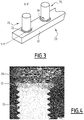
- the armor elements 29 each have an end section 32 introduced into the end piece 14.
- the end section 32 extends to a free end disposed in the end piece 14. It advantageously has a helical path. or pseudo-helical of axis AA 'in the end piece 14.
- the outer sheath 30 is intended to prevent the permeation of fluid from the exterior of the flexible pipe to the interior. It is advantageously made of a polymer material, in particular based on a polyolefin such as polyethylene or polypropylene, based on a polyamide such as PA11 or PA12, or based on a fluoropolymer such as polyfluoride of vinylidene (PVDF) or perfluoro alkoxy (PFA).
- a polymer material in particular based on a polyolefin such as polyethylene or polypropylene, based on a polyamide such as PA11 or PA12, or based on a fluoropolymer such as polyfluoride of vinylidene (PVDF) or perfluoro alkoxy (PFA).
- PVDF polyfluoride of vinylidene
- PFA perfluoro alkoxy
- the thickness of the outer sheath 30 is for example between 5 mm and 20 mm.
- the tensile armor layers are wound in a helix around its longitudinal axis, in opposite directions, at a precise winding angle equal to 55 °.
- the flexible pipe structure is then “balanced” and is therefore not subject to variations in length and to torsion effects in the event of high internal pressure.
- Such a structure does not include a pressure vault.
- the inner armor layer is no longer applied to the pressure vault, but is directly applied in contact with the pressure sheath.
- each end piece 14 comprises an end vault 50 and an external connecting cover 51 projecting axially towards the rear from the vault 50.
- the cover 51 defines, with the end vault 50, a receiving space 52 free ends 32 of the armor elements 29.
- the end piece 14 further comprises a front seal assembly 54 around the pressure sheath 20 and a rear seal assembly 55 around the outer sheath 30, shown schematically in FIG. figure 2 .
- the end vault 50 is intended to connect the pipe 10 to another connection end piece 14 or to terminal equipment, advantageously by means of an end flange 56.
- the vault 50 has a central bore intended to receive the end of the first sheath 20 and to allow the flow of the fluid circulating through the central passage 16 towards the outside of the pipe 10.
- the cover 51 has a tubular peripheral wall 58 extending around the axis A-A '.
- the peripheral wall 58 has a front edge 60 fixed to the end arch 50, radially away from the layers of armor 24, 25 and a rear edge 62 extending axially rearwardly beyond the arch. end 50, to which the rear assembly 55 is fixed.
- the cover 51 defines the space 52 radially outwards.
- a rear face of the end vault 50 axially delimits the space 52 towards the front.
- the volume of space 52 varies depending on the size of the mouthpiece. For example, for a pipe with an internal diameter equal to 6 ", or approximately 15.2 cm, the volume of the space 52 is approximately 30 liters, and for a pipe with an internal diameter equal to 16", or approximately 40, 6 cm, the volume of space 52 is approximately 60 liters.
- the front sealing assembly 54 is advantageously located at the front of the end piece 14, in contact with the arch 50, being offset axially forwards with respect to the rear sealing assembly 55.
- the front assembly 54 comprises a front crimping ring, intended to engage the pressure sheath 20.
- the front assembly 54 further comprises an intermediate stop ring for the pressure vault 28.
- the rear sealing assembly 55 is disposed at the rear of the front assembly 54. It comprises at least one rear crimping ring crimping the outer sheath 30.
- the front 54 and rear 55 assemblies are fixed with conventional fixing means, such as screws, to the arch 50 and to the cover 51 respectively.
- the tip 14 further comprises a solid filler material 64.
- the filling material 64 comprises for example a thermosetting polymeric resin of epoxy, polyimide (PI), polysulfone (PS), polyetheretherketone (PEEK), or poly (phenylene sulfide) (PPS) type.
- the filling material 64 is placed in the space 52 around the arch 50 and floods the end sections 32 of the armor elements 29.
- the filling material 64 completely fills the space 52.
- the end sections 32 of the armor elements 29 are each provided with at least one anchoring element 70, for example two anchoring elements 70 in the case shown.
- Each anchoring element 70 projects transversely from the end section 32 of the armor element 29 towards the outside of the pipe 10.
- the anchoring elements 70 are substantially aligned along the armor element 29, and separated from each other by a distance , measured relative to the center of each anchoring element, between 2 cm and 20 cm, preferably between 2 cm and 10 cm and advantageously between 2 cm and 5 cm.
- the anchoring element 70 is a metal part, for example cylindrical, having an axis X-X '.
- the anchoring element 70 has the shape of a threaded cylinder of axis X-X ', or else of a parallelepiped elongated in a direction X-X' transverse to the armor element 29.
- the axis XX 'of the anchoring element 70 is substantially orthogonal to a local axis YY' of the armor element 29 at the level of the fixing of the anchoring element 70 on the element d. armor 29.
- the anchor element 70 has a length, measured in a direction transverse to the YY 'axis of the armor element 29, and a width, measured in a dimension parallel to the YY' axis of the element. armor 29.
- a ratio between the length and the width of the anchoring element 70 is greater than 2, advantageously greater than 4.
- the anchoring element 70 is for example made of steel, and has a tensile strength limit greater than or equal to 400 MPa, advantageously greater than 600 MPa, as measured according to standards NF EN ISO 6892-1 (Edition November 2016 ), NF EN ISO 898-1 (May 2013 Edition) and NF EN ISO 3506-1 (January 2010 Edition).
- the anchoring element 70 is fixed to the armor element 29 by a weld 72 connecting a lower end 74 of the anchoring element 70 to the armor element 29.
- the length of the anchoring element 70 is greater than a thickness of the armor element 29, measured along the axis XX 'of the anchoring element 70, advantageously two times greater.
- the anchoring element or elements 70 are embedded in the filling material 64.
- a high ratio ensures better retention of the end section 32 of the armor element 29 in the receiving space 52, thanks to a better retention. interaction with filler 64.
- the weld 72 has an extent slightly greater than the width of the anchoring element 70, but less than a width of the armor element 29, measured in a direction orthogonal to the axis XX 'of the element anchor 70 and to the YY 'axis of the armor element 29.
- each anchoring element 70 has a maximum shear strength along the YY' axis of the armor element 29 greater than or equal to 15 kN, advantageously greater than 30 kN, as measured by standards NF EN ISO 6892-1 (Edition November 2016), NF EN ISO 898-1 (Edition May 2013) and NF EN ISO 3506-1 (Edition January 2010).
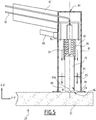
- This method is implemented using a fixing device 80, shown schematically on the figures 5 to 7 , suitable for fixing the anchor element 70.
- the device 80 is for example a welding gun, comprising control electronics able to implement the “fusion-forging” type fixing method.
- the device 80 comprises a tube 81 defining a cavity 82 in which the anchoring element 70 is loaded.
- the cavity 82 has the shape of an elongated cylinder, opening out at one end of the tube 81 through an opening 84.
- the device 80 comprises, in the cavity 82, a guide 85 adapted to guide the anchoring element 70 in the cavity 82, and a clamp 86 holding the anchoring element 70 in the cavity 82.
- the device 80 also comprises a handle 87, located on the opposite side of the tube 81 relative to the opening 84, suitable for handling the device 80, as well as a trigger 88 located close to the handle 87, capable of triggering the process. fixing the anchoring element 70.
- the device 80 comprises at least one neutral gas diffusion nozzle 90 opening into the cavity 82, connected to a pipe 92 for supplying neutral gas. So that the gas can flow in the cavity 82, the guide 85 has perforations 93, and the tube 81 also has radial perforations 94 at the opening 84.
- the device 80 further comprises a striker 95, able to apply a forging force on the anchoring element 70, as well as an electric current generator (not shown), able to generate at least one electric current through the device. anchor element 70 and armor element 29 when they are in contact with each other.
- the electric current generator When the anchoring element 70 is away from the armor element 29, the electric current generator is able to form a fusion electric arc between the anchoring element 70 and the element of armor 29.
- the device 80 is handled by an operator who holds it by the handle 87.
- an anchoring element 70 is provided, placed in the cavity 82 of the device 80.
- the anchoring element 70 is disposed with the lower end 74 oriented towards the opening 84, and is held in the clamp 86 by its free end.
- the anchoring element 70 is for example placed manually in the cavity 82 by the operator.
- the device 80 comprises a loading system capable of positioning the anchoring element 70, and of replacing it at the end of the fixing process. This makes it possible to implement a succession of fastenings of anchoring elements 70, with a time between each fastening less than or equal to 5 seconds.
- the lower end 74 of the anchoring element 70 is flat. But advantageously, the lower end 74 has a protuberance 95A projecting in the direction of the armor element 29. This facilitates the welding of the anchoring element 70 on the armor element 29.
- the tube 81 is brought into contact with an end section 32 of an armor element 29.
- the opening 84 of the cavity 82 extends in the armor element 29 and defines on the armor element 29 an attachment region 96 of the anchoring element 70.
- the anchoring element 70 is initially positioned in contact with the armor element 29.
- the device 80 is oriented so that the axis of the tube 81 is substantially orthogonal to the local axis of the armor element 29.
- the operator activates the trigger 88, and neutral gas is diffused by the nozzles 90.
- the neutral gas flows into the cavity 82, through the perforations 93, until the opening. 84.
- the neutral gas flows in particular around the anchoring element 70 and the fixing region 96, then along the radial perforations 94 to the outside.
- the neutral gas After a diffusion time of the order of 0.5 seconds to 2 seconds, the neutral gas has at least partially expelled the air around the anchor element 70 and the region 96 of attachment.
- the diffusion of neutral gas through the nozzles 90 is maintained during the following steps, and reduces the porosity in the weld 72, which improves its mechanical strength.
- a merger step is triggered after the broadcast time has elapsed.
- the duration of the diffusion step is advantageously programmed in the control electronics of the device 80, and the latter automatically triggers the next step once the time has elapsed. This duration is for example less than 1 second.
- an electric current is generated by the electric current generator through the anchoring element 70 and the armor element 29.
- the anchoring element 70 is then progressively moved away from the armor element 29, which leads to the generation of a fusion electric arc in the gas volume present between the anchoring element 70 and the element. armor 29 by the electric current generator.
- the electric arc of fusion forms in the cavity 82, in the flow of neutral gas.
- the electric fusion arc initially forms between the flat face of the lower end 74 of the anchoring element 70 or when it is present, between the protuberance 95A and the armor element 29, thanks to at the reduced distance between them.
- the weld pool 98 contains molten metal and has a width measured transversely to the axis XX 'greater than the width of the anchoring element 70 measured transversely to the axis X-X'.
- a forging step is then triggered by the control electronics of the device 80, during which the striker 95 exerts a force on the anchoring element 70 along the axis XX 'to forge the lower end 74 against the element d armor 29.
- the lower end 74 is immersed in the weld pool 98, fusing the lower end 74 of the anchoring element 70 and the attachment region 96.
- the method finally comprises a heat treatment step during which the temperature in the cavity 82 drops, which results in solidification of the molten metal and the formation of the weld 72.
- the drop in temperature in the cavity 82 is controlled to ensure good mechanical strength of the weld 72.
- a preheating heat treatment of the anchoring element 70 is carried out before the diffusion step to avoid cold cracking problems at the weld level.
- a post-heating heat treatment of the anchoring element 70 is also carried out after having allowed it to cool for the purpose of solidifying the weld.
- This post-heating heat treatment consists of a step of annealing the anchoring element 70. The anchoring element 70 is thus heated so as to bring it up to temperature in order to homogenize its microstructure and eliminate the residual stresses that may remain. following the implementation of the welding process.
- the method for fixing at least one anchoring element 70 described is particularly advantageous, since it requires a much shorter implementation time than that of the existing methods. In addition, it is carried out with a simpler and partially automated device 80, therefore requiring less technical skills on the part of the operator.
- the method for fixing the anchoring element 70 follows a short-time method not comprising the diffusion of neutral gas.
- the anchoring element 70 has a flange extending transversely to the axis XX 'around the lower end 74, in order to increase the transverse extent of the weld 72. This partly compensates for the lower mechanical strength of the weld 72 due to the formation of a porosity due to the absence of neutral gas around the molten bath 98 during the melting step.
- the melting step comprises a preliminary step of forming an initiation arc prior to the formation of the electric melting arc.
- the ignition arc has an intensity less than an intensity of the fusion electric arc and initiates the fusion of the material of the low end 74 and the attachment region 96, thereby speeding up the process.
- the diffusion of neutral gas is replaced by the placement of a ring of refractory material around the anchoring element 70.
- the ring widens by projecting around the lower end 74. .
- the ring bears on the armor element 29 during the step of placing the device 80, defining a closed space for protecting the molten pool 98 during the melting step.
- the ring contains and isolates the weld pool 98 from the surrounding air, reducing the formation of porosity in the weld 72.
- the ring is partially burned off during the melting step and is easily removed from the anchor 70 after the heat treatment step is completed.
- the method of mounting the end piece 14 according to the invention is carried out as follows.
- each end section 32 of the inner armor layer 24 is unfolded forward.
- At least one anchoring element 70 is fixed on each end section 32, according to the fixing method described above.
- at least two anchoring elements 70 are fixed on each end section 32.
- the end sections 32 are spaced from one another by a distance of the order of a few millimeters.
- At least one anchoring element 70 is fixed on each end section 32 of the elements 29 of the outer armor layer 25 according to the same fixing method as that used for the inner armor layer 24.
- each end section 32 of the outer armor layer 25 is unfolded forward.
- the fixing of at least one anchoring element 70 on the end sections 32 of the armor elements 29 of the armor layers 24, 25 can be carried out before their unfolding forwards.
- the cover 51 is then put in place and fixed to the arch 50, thus forming the reception space 52 around the end sections 32.
- the rear sealing assembly 55 is then put in place and is fixed to the cover 51.
- the end sections 32 of the armor elements 29 of the outer armor layer 25 are folded backwards to allow access to the elements 29 of the inner armor layer 24.
- At least one anchoring element 70 is fixed to each end section 32 of the inner armor layer 24, according to the fixing method described above.
- at least two anchoring elements 70 are fixed on each end section 32.
- At least one anchoring element 70 is fixed on each end section 32 of the elements 29 of the outer armor layer 25 according to the same fixing method as that used for the inner armor layer 24. Then, each end section 32 of the outer armor layer 25 is unfolded forward.
- the fixing of at least one anchoring element 70 on the end sections 32 of the armor elements 29 of the outer armor layer 25 is carried out after their unfolding forwards.
- the end sections 32 of the armor layers 24, 25 are arranged during the manufacture of the end piece 10 for present their conformation as close as possible to their natural conformation, in which they are least constrained.
- At least one anchoring element 70 is attached to each section. end 32 of the armor layers 24, 25 according to the same fixing method as that described above.
- at least two anchoring elements 70 are fixed on each end section 32.
- the cover 51 is then put in place and fixed to the arch 50, thus forming the reception space 52 around the end sections 32.
- the rear sealing assembly 55 is then put in place and is fixed to the cover 51.
- the outer sheath 30 is machined to reveal the outer armor layer 25.
- a rear cannula, an element forming part of the rear sealing assembly 55 is then inserted between the layer. armor 25 and the outer sheath 30.
- a first fixing collar of the "band-it" type is then placed around the outer armor layer 25, near the rear cannula, leaving a sufficient length between the first fixing collar and the rear cannula to allow the fixing of at least one anchoring element 70.
- At least one anchoring element 70 is then fixed on each end section 32 of the elements 29 of the outer armor layer 25, between the first fixing collar and the rear cannula, according to the same fixing method as that described. above.
- at least two anchoring elements 70 are fixed to each end section 32 of the armor elements 29.
- all of the excess lengths of the end sections 32 of each armor element are cut. 29 forming the outer armor layer 25, located in front of the fixing collar.
- Removing the extra lengths of the armor elements 29 of the layer 25 allows access to the inner armor layer 24.
- a second fixing collar is placed around the layer of inner armor 24 leaving a sufficient length between the second fixing collar and the outer armor layer 25, to allow the fixing of at least one anchoring element 70.
- At least one anchoring element is then fixed on each end section 32 of the elements 29 of the inner armor layer 24, between the second fixing collar and the armor layer 25, according to the same fastening method as previously.
- at least two anchoring elements 70 are fixed to each end section 32 of the armor layer 24.
- the cover 51 is then put in place and fixed to the arch 50, thus forming the reception space 52 around the end sections 32.
- the latter method of end fitting mounting has the advantage of shortening the necessary total length of the end fitting as well as reducing the total cost of a flexible pipe having such a fitting. Indeed, the length of the end sections 32 being reduced, it is no longer necessary to provide for the provision of an end cap 50 having a zone having a frustoconical section.
- the filling material 64 is then introduced into the space 52, advantageously in fluid form.
- the material 64 fills the space 52 and solidifies between the arch 50 and the cover 51 around the end sections 32 of the armor elements 29 and around the anchoring elements 70.
- the material 64 solidifies at room temperature, corresponding to the temperature inside the nozzle, and under atmospheric pressure. In cases where the outside temperature is less than 15 ° C., heating means are used to control the solidification of the material 64, for example a heating blanket.
- the solidification time is of the order of a few hours, more particularly from 3 hours to 6 hours.
- the end sections 32 are then embedded in the filling material 64.
- the end piece 14 In operation, when the end piece 14 is connected to another end piece or to a surface assembly, the axial tension transmitted by the armor layers 24, 25 resulting from the weight of the pipe 10 is taken up by the sections 32 embedded in the filling material 82, and more particularly by the anchoring elements 70.
Description
La présente invention concerne un procédé de fixation d'au moins un élément d'ancrage transverse sur un élément d'armure destiné à être reçu dans un embout d'extrémité d'une conduite flexible. L'invention concerne également une conduite flexible et une méthode de montage d'un embout de cette conduite flexible.The present invention relates to a method for fixing at least one transverse anchoring element to an armor element intended to be received in an end piece of a flexible pipe. The invention also relates to a flexible pipe and a method of mounting an end piece of this flexible pipe.
La conduite est en particulier une conduite flexible de type non liée (« unbonded ») destinée au transport d'hydrocarbures à travers une étendue d'eau, tel qu'un océan, une mer, un lac ou une rivière, ou à l'injection d'eau pour la stimulation de puits.The pipe is in particular a flexible pipe of the unbonded type intended for the transport of hydrocarbons through a body of water, such as an ocean, a sea, a lake or a river, or to the water injection for well stimulation.
Une telle conduite flexible est par exemple réalisée suivant les documents normatifs API 17J (Spécification for Unbonded Flexible Pipe), API RP 17B (Recommended Practice for Flexible Pipe) et API 16C (Choke and Kill Equipment) établis par l'American Petroleum Institute.Such a flexible pipe is for example produced according to the normative documents API 17J (Specification for Unbonded Flexible Pipe), API RP 17B (Recommended Practice for Flexible Pipe) and API 16C (Choke and Kill Equipment) established by the American Petroleum Institute.
La conduite est généralement formée d'un ensemble de couches concentriques et superposées. Elle est considérée comme « non liée » au sens de la présente invention dès lors qu'au moins une des couches de la conduite est apte à se déplacer longitudinalement par rapport aux couches adjacentes lors d'une flexion de la conduite. En particulier, une conduite non liée est une conduite dépourvue de matériaux liants raccordant des couches formant la conduite.The pipe is generally formed from a set of concentric and superimposed layers. It is considered to be “unbound” within the meaning of the present invention when at least one of the layers of the pipe is able to move longitudinally with respect to the adjacent layers during bending of the pipe. In particular, an unbound pipe is a pipe devoid of binding materials connecting layers forming the pipe.
La conduite est généralement disposée à travers une étendue d'eau, entre un ensemble de fond, destiné à recueillir le fluide exploité dans le fond de l'étendue d'eau et un ensemble de surface flottant destiné à collecter et à distribuer le fluide. L'ensemble de surface peut être une plateforme semi-submersible, un FPSO ou un autre ensemble flottant.The pipe is generally arranged through a body of water, between a bottom assembly, intended to collect the fluid operated in the bottom of the body of water, and a floating surface assembly intended to collect and distribute the fluid. The surface assembly can be a semi-submersible platform, an FPSO or other floating assembly.
Dans certains cas, pour l'exploitation de fluides en eaux profondes, la conduite flexible présente une longueur supérieure à 800 m. Les extrémités de la conduite présentent des embouts pour le raccordement à l'ensemble de fond et à l'ensemble de surface.In certain cases, for the exploitation of fluids in deep water, the flexible pipe has a length of more than 800 m. The ends of the pipe have end caps for connection to the bottom assembly and the surface assembly.
Ces conduites subissent des efforts très élevés en traction axiale, notamment lorsque l'étendue d'eau dans laquelle est disposée la conduite est très profonde. Ces efforts sont repris par une ou plusieurs couches d'armures de traction composées d'éléments d'armure filiformes en acier enroulés à pas long autour des couches internes de la conduite, et dont les extrémités sont fixées dans les embouts d'extrémité.These pipes are subjected to very high axial traction forces, in particular when the body of water in which the pipe is located is very deep. These forces are taken up by one or more layers of tensile armor composed of wire-like armor elements of steel wound at a long pitch around the internal layers of the pipe, and the ends of which are fixed in the end caps.
Dans ce cas, l'embout supérieur reliant la conduite à l'ensemble de surface doit reprendre une tension axiale très importante, qui peut atteindre plusieurs centaines de tonnes.In this case, the upper end piece connecting the pipe to the surface assembly must take up a very high axial tension, which can reach several hundred tonnes.
La tension axiale présente non seulement une valeur moyenne élevée, mais aussi des variations permanentes en fonction des mouvements verticaux de l'ensemble de surface et de la conduite, sous l'effet de l'agitation de l'étendue d'eau provoquée par la houle ou par les vagues.The axial tension has not only a high average value, but also permanent variations as a function of the vertical movements of the whole surface and of the pipe, under the effect of the agitation of the body of water caused by the swell or by waves.
Les variations de tension axiale peuvent atteindre plusieurs dizaines de tonnes et se répéter continuellement durant la durée de service de la conduite. En 20 ans, la conduite peut être amenée à subir un nombre de cycles en tension important. Par exemple, plus de 20 millions de cycles peuvent se produire.The variations in axial tension can reach several tens of tons and be repeated continuously during the service life of the pipe. In 20 years, the pipe may have to undergo a large number of voltage cycles. For example, more than 20 million cycles can occur.
Il est donc nécessaire d'assurer une fixation particulièrement robuste entre les couches d'armures de traction et le corps de l'embout d'extrémité. Pour cela, il est connu d'introduire les extrémités des éléments d'armure dans un espace de réception défini par l'embout d'extrémité, puis de remplir l'espace de réception avec un matériau comme une résine thermodurcissable, pour emprisonner les extrémités des éléments d'armure.It is therefore necessary to ensure a particularly robust attachment between the layers of tensile armor and the body of the end piece. For this, it is known to introduce the ends of the armor elements into a receiving space defined by the end cap, then to fill the receiving space with a material such as a thermosetting resin, to trap the ends. elements of armor.
Pour améliorer la tenue des éléments d'armure,
Ce procédé peut encore être amélioré. En effet, les éléments d'ancrage sont fixés aux éléments d'armure par soudage longitudinal le long des faces en contact, par exemple par soudage à l'arc électrique. Ce procédé de fixation nécessite l'intervention de personnel qualifié, pour le soudage. De plus, il requiert un temps important, puisqu'au moins un élément d'ancrage doit être fixé sur chaque extrémité de chaque élément d'armure, par deux soudures longitudinales à chaque fois.This process can still be improved. Indeed, the anchoring elements are fixed to the armor elements by longitudinal welding along the surfaces in contact, for example by electric arc welding. This fixing process requires the intervention of qualified personnel for welding. In addition, it requires a long time, since at least one anchoring element must be fixed on each end of each armor element, by two longitudinal welds each time.
Un but de l'invention est d'assurer une fixation robuste des éléments d'armure dans un embout de conduite flexible, de manière simple et très rapide.An aim of the invention is to ensure robust attachment of the armor elements in a flexible pipe end piece, in a simple and very rapid manner.
A cet effet, l'invention a pour objet un procédé de fixation du type précité, caractérisé en que le procédé comprend les étapes suivantes :
- fourniture d'un dispositif de fixation présentant une cavité recevant un élément d'ancrage ;
- mise en place d'une ouverture de la cavité en regard de l'élément d'armure ;
- fusion d'une extrémité de l'élément d'ancrage en regard de l'élément d'armure et d'une région de l'élément d'armure en regard de l'élément d'ancrage, dans la cavité du dispositif de fixation ;
- forgeage de l'élément d'ancrage transversalement sur l'élément d'armure, par le dispositif de fixation ; et
- formation d'une soudure liant l'élément d'ancrage et l'élément d'armure.
- providing a fastening device having a cavity receiving an anchoring element;
- placing an opening in the cavity facing the armor element;
- fusion of one end of the anchoring element facing the armor element and a region of the armor element facing the anchoring element, in the cavity of the fixing device ;
- forging of the anchoring element transversely on the armor element, by the fixing device; and
- formation of a weld between the anchoring element and the armor element.
Le procédé selon l'invention peut comprendre l'une ou plusieurs des caractéristiques suivantes, prise(s) isolément ou suivant toute combinaison techniquement possible :
- le procédé comprend une étape de traitement thermique de l'élément d'ancrage et de l'élément d'armure postérieure à l'étape de forgeage, la soudure liant l'élément d'ancrage et l'élément d'armure se formant lors de l'étape de traitement thermique ;
- la soudure présente une étendue transversale inférieure à une largeur de l'élément d'armure ;
- l'étape de fusion comprend la formation d'un arc électrique de fusion entre l'élément d'ancrage et l'élément d'armure ;
- le procédé comprend une étape de diffusion d'un gaz neutre autour d'au moins l'un de l'extrémité de l'élément d'ancrage ou de la région de l'élément d'armure, l'étape de diffusion ayant lieu pendant les étapes de fusion et de forgeage ;
- l'étape de fusion comprend la formation d'un arc d'amorçage préalable à la formation de l'arc électrique de fusion, l'arc d'amorçage présentant une intensité inférieure à une intensité de l'arc électrique de fusion ;
- une bague réfractaire est positionnée autour de l'extrémité de l'élément d'ancrage en regard de l'élément d'armure au cours de l'étape de mise en place ;
- un ratio entre une longueur de l'élément d'ancrage, mesurée selon une direction transverse à l'élément d'armure, et une largeur de l'élément d'ancrage, mesurée selon une direction parallèle à l'élément d'armure, est supérieur à 2, avantageusement supérieur à 4 ;
- la longueur de l'élément d'ancrage est supérieure à une épaisseur de l'élément d'armure, mesurée selon la même direction que la longueur de l'élément d'ancrage, avantageusement deux fois supérieure à l'épaisseur de l'élément d'armure ;
- l'élément d'ancrage est sensiblement cylindrique et présente un axe sensiblement perpendiculaire à un axe local de l'élément d'armure ;
- le procédé comprend une succession de fixations d'éléments d'ancrage transverses, chaque fixation comprenant les étapes de fourniture, de mise en place, de fusion et de forgeage, une durée séparant chaque fixation étant inférieure ou égale à 1 minute, avantageusement inférieure à 30 secondes ;
- les éléments d'ancrage sont fixés séparés les uns des autres d'une distance le long de l'élément d'armure comprise entre 2 cm et 20 cm, préférentiellement entre 2 cm et 10 cm et avantageusement entre 2 cm et 5 cm ; et
- l'élément d'ancrage est fait à base d'un acier présentant une résistance mécanique en traction supérieure ou égale à 400 MPa.
- the method comprises a step of heat treatment of the anchoring element and of the armor element subsequent to the forging step, the weld between the anchoring element and the armor element being formed during the heat treatment step;
- the weld has a transverse extent less than a width of the armor element;
- the fusion step comprises forming a fusion electric arc between the anchoring element and the armor element;
- the method comprises a step of diffusing a neutral gas around at least one of the end of the anchoring member or the region of the armor member, the step of diffusing taking place during the smelting and forging stages;
- the melting step comprises forming an initiation arc prior to the formation of the fusion electric arc, the initiation arc having an intensity less than an intensity of the fusion electric arc;
- a refractory ring is positioned around the end of the anchoring element facing the armor element during the installation step;
- a ratio between a length of the anchoring element, measured in a direction transverse to the armor element, and a width of the anchoring element, measured in a direction parallel to the armor element, is greater than 2, advantageously greater than 4;
- the length of the anchoring element is greater than a thickness of the armor element, measured in the same direction as the length of the anchoring element, advantageously twice the thickness of the element armor;
- the anchoring element is substantially cylindrical and has an axis substantially perpendicular to a local axis of the armor element;
- the method comprises a succession of fastenings of transverse anchoring elements, each fastening comprising the steps of supplying, positioning, melting and forging, a time separating each attachment being less than or equal to 1 minute, advantageously less than 30 seconds;
- the anchoring elements are fixed separated from each other by a distance along the armor element of between 2 cm and 20 cm, preferably between 2 cm and 10 cm and advantageously between 2 cm and 5 cm; and
- the anchoring element is made from a steel having a mechanical tensile strength greater than or equal to 400 MPa.
L'invention a également pour objet une méthode de montage d'un embout d'extrémité de conduite flexible comprenant les étapes suivantes :
- fourniture d'une conduite flexible comprenant :
- au moins une gaine tubulaire délimitant un passage de circulation ; et
- au moins une couche d'armures de traction disposée extérieurement par rapport à la gaine tubulaire, la couche d'armures comprenant une pluralité d'éléments d'armure filiformes ;
- dégagement d'un tronçon d'extrémité de chaque élément d'armure ;
- mise en place d'une voûte d'extrémité à une extrémité de la conduite ;
- fixation d'au moins un élément d'ancrage sur chaque élément d'armure par un procédé selon l'invention ;
- mise en place et fixation d'un capot sur la voûte d'extrémité, formant un espace de réception des tronçons d'extrémité des éléments d'amure ;
- introduction d'un matériau de remplissage dans l'espace, noyant les éléments d'ancrage ; et
- solidification du matériau de remplissage autour des tronçons d'extrémité et des éléments d'ancrage.
- au moins une gaine tubulaire délimitant un passage de circulation ;
- au moins une couche d'armures de traction disposée extérieurement par rapport à la gaine tubulaire, la couche d'armures comprenant une pluralité d'éléments d'armure filiformes ; et
- au moins un embout d'extrémité situé à une extrémité de la conduite,
caractérisée en ce que chaque tronçon d'extrémité présente au moins un élément d'ancrage faisant saillie de façon transverse, l'élément d'ancrage étant noyé dans le matériau de remplissage, l'élément d'ancrage ayant été fixé au tronçon d'extrémité par un procédé selon l'invention.A subject of the invention is also a method of mounting a flexible pipe end piece comprising the following steps:
- supply of a flexible pipe comprising:
- at least one tubular sheath delimiting a circulation passage; and
- at least one tensile armor layer disposed externally with respect to the tubular sheath, the armor layer comprising a plurality of filiform armor elements;
- releasing an end section of each armor element;
- placing an end vault at one end of the pipe;
- fixing of at least one anchoring element to each armor element by a method according to the invention;
- placement and fixing of a cover on the end vault, forming a space for receiving the end sections of the tack elements;
- introduction of a filling material into the space, embedding the anchoring elements; and
- solidification of the filling material around the end sections and anchoring elements.
- at least one tubular sheath delimiting a circulation passage;
- at least one tensile armor layer disposed externally with respect to the tubular sheath, the armor layer comprising a plurality of filiform armor elements; and
- at least one end piece located at one end of the pipe,
characterized in that each end section has at least one anchoring element projecting transversely, the anchoring element being embedded in the filling material, the anchoring element having been fixed to the end section by a method according to the invention.
L'invention sera mieux comprise à la lecture de la description qui va suivre, donnée uniquement à titre d'exemple, et faite en se référant aux dessins annexés, sur lesquels :
- la
figure 1 est une vue en perspective partiellement écorchée d'un tronçon d'une conduite flexible ; - la
figure 2 est une vue schématique en coupe suivant un plan axial médian d'un embout de la conduite flexible de lafigure 1 ; - la
figure 3 est une vue en perspective de l'extrémité d'un élément d'armure inséré dans l'embout de lafigure 2 ; - la
figure 4 est une photographie en coupe illustrant une soudure formée entre un élément d'ancrage et un élément d'armure par le procédé selon l'invention ; et - les
figures 5 ,6 et7 sont des vues en coupe de côté des étapes du procédé de fixation d'un élément d'ancrage sur l'extrémité d'un élément d'armure, tel que visible sur lafigure 3 .
- the
figure 1 is a partially cut-away perspective view of a section of a flexible pipe; - the
figure 2 is a schematic sectional view along a median axial plane of an end piece of the flexible pipe of thefigure 1 ; - the
figure 3 is a perspective view of the end of a piece of armor inserted into the tip of thefigure 2 ; - the
figure 4 is a sectional photograph illustrating a weld formed between an anchoring element and an armor element by the method according to the invention; and - the
figures 5 ,6 and7 are side sectional views of the steps in the method of attaching an anchoring element to the end of an armor element, as shown in the figurefigure 3 .
Dans tout ce qui suit, les termes « extérieur » et « intérieur » s'entendent généralement de manière radiale par rapport à un axe A-A' de la conduite, le terme « extérieur » s'entendant comme relativement plus éloigné radialement de l'axe A-A' et le terme « intérieur » s'étendant comme relativement plus proche radialement de l'axe A-A' de la conduite.In what follows, the terms “exterior” and “interior” are generally understood to be understood radially with respect to an axis AA ′ of the pipe, the term “exterior” being understood as being relatively more radially distant from the axis. AA 'and the term "interior" extending as relatively closer radially to the axis AA' of the pipe.
Les termes « avant » et « arrière » s'entendent de manière axiale par rapport à un axe A-A' de la conduite, le terme « avant » s'entendant comme relativement plus éloigné du milieu de la conduite et plus proche d'une de ses extrémités, le terme « arrière » s'entendant comme relativement plus proche du milieu de la conduite et plus éloigné d'une de ses extrémités. Le milieu de la conduite est le point de la conduite situé à égale distance des deux extrémités de cette dernière.The terms "front" and "rear" are understood axially with respect to an axis AA 'of the pipe, the term "front" being understood as relatively further from the middle of the pipe and closer to one of the pipes. its ends, the term “rear” being understood as being relatively closer to the middle of the pipe and further away from one of its ends. The middle of the pipe is the point in the pipe that is equidistant from both ends of the pipe.
Une première conduite flexible 10 selon l'invention est illustrée partiellement par la
La conduite flexible 10 comporte un tronçon central 12 illustré en partie sur la
En référence à la
La conduite flexible 10 est destinée à être disposée à travers une étendue d'eau (non représentée) dans une installation d'exploitation de fluide, notamment d'hydrocarbures.The
L'étendue d'eau est par exemple, une mer, un lac ou un océan. La profondeur de l'étendue d'eau au droit de l'installation d'exploitation de fluide est par exemple comprise entre 500 m et 3000 m.The body of water is, for example, a sea, a lake or an ocean. The depth of the body of water to the right of the fluid exploitation installation is for example between 500 m and 3000 m.
L'installation d'exploitation de fluide comporte un ensemble de surface notamment flottant et un ensemble de fond (non représentés) qui sont généralement raccordés entre eux par la conduite flexible 10.The fluid exploitation installation comprises a surface assembly, in particular a floating surface, and a bottom assembly (not shown) which are generally connected to one another by the
La conduite flexible 10 est de préférence une conduite « non liée » (désignée par le terme anglais « unbonded »).The
Au moins deux couches adjacentes de la conduite flexible 10 sont libres de se déplacer longitudinalement l'une par rapport à l'autre lors d'une flexion de la conduite. Avantageusement, toutes les couches de la conduite flexible sont libres de se déplacer l'une par rapport à l'autre. Une telle conduite est par exemple décrite dans les documents normatifs publiés par
Comme illustré par la
Selon l'invention, la conduite 10 comporte au moins une première gaine tubulaire 20 à base de matériau polymère constituant avantageusement une gaine de pression.According to the invention, the
La conduite 10 comporte en outre au moins une couche d'armures de traction 24, 25 disposée extérieurement par rapport à la première gaine 20.The
Avantageusement, et selon l'utilisation souhaitée, la conduite 10 comporte en outre une carcasse interne 26 disposée à l'intérieur de la gaine de pression 20, une voûte de pression 28 intercalée entre la gaine de pression 20 et la ou les couches d'armures de traction 24, 25 et une gaine externe 30, destinée à la protection de la conduite 10.Advantageously, and depending on the desired use, the
De manière connue, la gaine de pression 20 est destinée à confiner de manière étanche le fluide transporté dans le passage 16. Elle est formée en matériau polymère, par exemple à base d'une polyoléfine tel que du polyéthylène ou du polypropylène, à base d'un polyamide tel que du PA11 ou du PA12, ou à base d'un polymère fluoré tel que du polyfluorure de vinylidène (PVDF) ou du perfluoro alkoxy (PFA).In known manner, the
L'épaisseur de la gaine de pression 20 est par exemple comprise entre 5 mm et 20 mm.The thickness of the
La carcasse 26, lorsqu'elle est présente, est formée par exemple d'un feuillard métallique profilé, enroulé en spirale. Les spires du feuillard sont avantageusement agrafées les unes aux autres, ce qui permet de reprendre les efforts radiaux d'écrasement.The
Dans cet exemple, la carcasse 26 est disposée à l'intérieur de la gaine de pression 20. La conduite est alors désignée par le terme anglais « rough bore » en raison de la géométrie de la carcasse 26In this example, the
En variante (non représentée), la conduite flexible 10 est dépourvue de carcasse interne 26, elle est alors désignée par le terme anglais « smooth bore ».As a variant (not shown), the
L'enroulement hélicoïdal du feuillard métallique profilé formant la carcasse 26 est à pas court, c'est-à-dire qu'il présente un angle d'hélice de valeur absolue proche de 90°, typiquement compris entre 75° et 90°.The helical winding of the profiled metal strip forming the
Dans cet exemple, la voûte de pression 28 est destinée à reprendre les efforts liés à la pression régnant à l'intérieur de la gaine de pression 20. Elle est par exemple formée d'un fil profilé métallique entouré en hélice autour de la gaine 20. Le fil profilé présente généralement une géométrie complexe, notamment en forme de Z, comme dans l'exemple représenté sur la
La voûte de pression 28 est enroulée en hélice à pas court autour de la gaine de pression 20, c'est-à-dire avec un angle d'hélice de valeur absolue proche de 90°, typiquement compris entre 75° et 90°.The
La conduite flexible 10 selon l'invention comprend au moins une couche d'armures 24, 25 formée d'un enroulement hélicoïdal d'au moins un élément d'armure 29 allongé.The
Typiquement, la conduite flexible comprend au moins deux couches d'armures mais elle peut comprendre plus de deux couches d'armures, par exemple quatre couches d'armures.Typically, the flexible pipe comprises at least two layers of armor but it can include more than two layers of armor, for example four layers of armor.
Dans l'exemple représenté sur la
Chaque couche d'armures 24, 25 comporte des éléments d'armure 29 longitudinaux enroulés en hélice à pas long autour de l'axe A-A' de la conduite.Each
Par « enroulé à pas long », on entend que la valeur absolue de l'angle d'hélice est inférieure à 60°, et est typiquement comprise entre 25° et 55°.By "long pitch wound" is meant that the absolute value of the helix angle is less than 60 °, and is typically between 25 ° and 55 °.
Les éléments d'armure 29 d'une première couche 24 sont enroulés généralement suivant un angle opposé par rapport aux éléments d'armure 29 d'une deuxième couche 25. Ainsi, si l'angle d'enroulement des éléments d'armure 29 de la première couche 24 est égal à + α, α étant compris entre 25° et 55°, l'angle d'enroulement des éléments d'armure 29 de la deuxième couche d'armure 25 disposée au contact de la première couche d'armures 24 est par exemple égal à - α°.The
Les éléments d'armure 29 sont par exemple formés par des fils métalliques, notamment des fils en acier, ou par des rubans en matériau composite, par exemple des rubans renforcés de fibres de carbone.The
Comme on le verra plus bas, en référence à la
La gaine externe 30 est destinée à empêcher la perméation de fluide depuis l'extérieur de la conduite flexible vers l'intérieur. Elle est avantageusement réalisée en matériau polymère, notamment à base d'une polyoléfine tel que du polyéthylène ou du polypropylène, à base d'un polyamide tel que du PA11 ou du PA12, ou à base d'un polymère fluoré tel que du polyfluorure de vinylidène (PVDF) ou du perfluoro alkoxy (PFA).The
L'épaisseur de la gaine externe 30 est par exemple comprise entre 5 mm et 20 mm.The thickness of the
Selon une variante de réalisation de la conduite flexible de la
Comme illustré par la
L'embout 14 comporte en outre un ensemble avant 54 d'étanchéité autour de la gaine de pression 20 et un ensemble arrière 55 d'étanchéité autour de la gaine extérieure 30, représentés schématiquement sur la
Dans cet exemple, la voûte d'extrémité 50 est destinée à raccorder la conduite 10 à un autre embout de connexion 14 ou à des équipements terminaux, avantageusement par l'intermédiaire d'une bride d'extrémité 56.In this example, the
La voûte 50 présente un alésage central destiné à recevoir l'extrémité de la première gaine 20 et à permettre l'écoulement du fluide circulant à travers le passage central 16 vers l'extérieur de la conduite 10.The
Le capot 51 comporte une paroi périphérique 58 tubulaire s'étendant autour de l'axe A-A'. La paroi périphérique 58 présente un bord avant 60 fixé sur la voûte d'extrémité 50, à l'écart radialement des couches d'armures 24, 25 et un bord arrière 62 s'étendant axialement vers l'arrière au-delà de la voûte d'extrémité 50, sur lequel est fixé l'ensemble arrière 55.The
Le capot 51 délimite l'espace 52 radialement vers l'extérieur. Une face arrière de la voûte d'extrémité 50 délimite axialement l'espace 52 vers l'avant.The
Le volume de l'espace 52 varie selon la taille de l'embout. Par exemple, pour une conduite de diamètre interne égal à 6", soit environ 15,2 cm, le volume de l'espace 52 est environ de 30 litres, et pour une conduite de diamètre interne égal à 16", soit environ 40,6 cm, le volume de l'espace 52 est environ de 60 litres.The volume of
L'ensemble avant 54 d'étanchéité est avantageusement situé à l'avant de l'embout 14, en contact avec la voûte 50, en étant décalé axialement vers l'avant par rapport à l'ensemble arrière 55 d'étanchéité.The
De manière connue, l'ensemble avant 54 comporte une bague avant de sertissage, destinée à venir en prise sur la gaine de pression 20.In known manner, the
Dans l'exemple représenté sur les
L'ensemble arrière 55 d'étanchéité est disposé à l'arrière de l'ensemble avant 54. Il comporte au moins une bague arrière de sertissage sertissant la gaine externe 30.The
Les ensembles avant 54 et arrière 55 sont fixés avec des moyens de fixation conventionnels, comme des vis, à la voûte 50 et au capot 51 respectivement.The front 54 and rear 55 assemblies are fixed with conventional fixing means, such as screws, to the arch 50 and to the
L'embout 14 comporte en outre un matériau 64 de remplissage solide. Le matériau de remplissage 64 comprend par exemple une résine polymérique thermodurcissable de type epoxy, polyimide (PI), polysulfone (PS), polyetheretherketone (PEEK), ou poly(sulfure de phénylène) (PPS).The
Le matériau de remplissage 64 est disposé dans l'espace 52 autour de la voûte 50 et noie les tronçons d'extrémité 32 des éléments d'armure 29. Avantageusement, le matériau de remplissage 64 remplit totalement l'espace 52.The filling
Comme représenté sur les
Dans le cas où le tronçon d'extrémité 32 est muni de plusieurs éléments d'ancrage 70, les éléments d'ancrage 70 sont sensiblement alignés le long de l'élément d'armure 29, et séparés les uns des autres d'une distance, mesurée par rapport au centre de chaque élément d'ancrage, comprise entre 2 cm et 20 cm, préférentiellement entre 2 cm et 10 cm et avantageusement entre 2 cm et 5 cm.In the case where the
L'élément d'ancrage 70 est une pièce métallique, par exemple cylindrique, présentant un axe X-X'. En variante, l'élément d'ancrage 70 présente une forme de cylindre fileté d'axe X-X', ou encore de parallélépipède allongé selon une direction X-X' transverse à l'élément d'armure 29.The anchoring
Avantageusement, l'axe X-X' de l'élément d'ancrage 70 est sensiblement orthogonal à un axe local Y-Y' de l'élément d'armure 29 au niveau de la fixation de l'élément d'ancrage 70 sur l'élément d'armure 29.Advantageously, the axis XX 'of the anchoring
L'élément d'ancrage 70 présente une longueur, mesurée dans une direction transverse à l'axe Y-Y' de l'élément d'armure 29, et une largeur, mesurée dans une dimension parallèle à l'axe Y-Y' de l'élément d'armure 29.The
Selon l'invention, un ratio entre la longueur et la largeur de l'élément d'ancrage 70 est supérieur à 2, avantageusement supérieur à 4.According to the invention, a ratio between the length and the width of the anchoring
L'élément d'ancrage 70 est par exemple en acier, et présente une limite de résistance en traction supérieure ou égale à 400 MPa, avantageusement supérieure à 600 MPa, telle que mesurée selon les normes NF EN ISO 6892-1 (Edition Novembre 2016), NF EN ISO 898-1 (Edition Mai 2013) et NF EN ISO 3506-1 (Edition Janvier 2010).The anchoring
En référence à la
La longueur de l'élément d'ancrage 70 est supérieure à une épaisseur de l'élément d'armure 29, mesurée selon l'axe X-X' de l'élément d'ancrage 70, avantageusement deux fois supérieure.The length of the anchoring
Le ou les éléments d'ancrage 70 sont noyés dans le matériau de remplissage 64. Un ratio élevé assure un meilleur maintien du tronçon d'extrémité 32 de l'élément d'armure 29 dans l'espace 52 de réception, grâce à une meilleure interaction avec le matériau de remplissage 64.The anchoring element or
Comme illustré sur la
La soudure 72 présente une résistance mécanique élevée au cisaillement selon une direction parallèle à l'axe Y-Y' de l'élément d'armure 29. Ainsi, chaque élément d'ancrage 70 présente une tenue maximale en cisaillement selon l'axe Y-Y' de l'élément d'armure 29 supérieure ou égale à 15 kN, avantageusement supérieure à 30 kN, telle que mesurée par les normes NF EN ISO 6892-1 (Edition Novembre 2016), NF EN ISO 898-1 (Edition Mai 2013) et NF EN ISO 3506-1 (Edition Janvier 2010).The
Le procédé de fixation de l'élément d'ancrage 70 sur l'élément d'armure 29 va maintenant être décrit, en référence aux
Ce procédé est mis en œuvre à l'aide d'un dispositif 80 de fixation, représenté schématiquement sur les
Le dispositif 80 est par exemple un pistolet de soudage, comprenant une électronique de contrôle apte à mettre en œuvre le procédé de fixation de type « fusion-forgeage ».The
Le dispositif 80 comprend un tube 81 définissant une cavité 82 dans laquelle est chargé l'élément d'ancrage 70. La cavité 82 présente la forme d'un cylindre allongé, débouchant à une extrémité du tube 81 par une ouverture 84.The
Le dispositif 80 comprend, dans la cavité 82, un guide 85 adapté pour guider l'élément d'ancrage 70 dans la cavité 82, et une pince 86 maintenant l'élément d'ancrage 70 dans la cavité 82.The
Le dispositif 80 comprend également une poignée 87, située du côté opposé du tube 81 par rapport à l'ouverture 84, adaptée pour la manutention du dispositif 80, ainsi qu'un déclencheur 88 situé proche de la poignée 87, apte à déclencher le procédé de fixation de l'élément d'ancrage 70.The
Le dispositif 80 comprend au moins une buse 90 de diffusion de gaz neutre débouchant dans la cavité 82, reliée à un tuyau 92 d'approvisionnement en gaz neutre. Pour que le gaz puisse s'écouler dans la cavité 82, le guide 85 présente des perforations 93, et le tube 81 présente également des perforations radiales 94 au niveau de l'ouverture 84.The
Le dispositif 80 comprend en outre un percuteur 95, apte à appliquer une force de forgeage sur l'élément d'ancrage 70, ainsi qu'un générateur de courant électrique (non représenté), apte à générer au moins un courant électrique à travers l'élément d'ancrage 70 et l'élément d'armure 29 quand ils sont au contact l'un de l'autre.The
Lorsque l'élément d'ancrage 70 est à l'écart de l'élément d'armure 29, le générateur de courant électrique est apte à former un arc électrique de fusion entre l'élément d'ancrage 70 et l'élément d'armure 29.When the anchoring
Le dispositif 80 est manipulé par un opérateur qui le tient par la poignée 87.The
Comme représenté sur la
L'élément d'ancrage 70 est par exemple mis en place manuellement dans la cavité 82 par l'opérateur.The anchoring
En variante, le dispositif 80 comporte un système de chargement apte à mettre en place l'élément d'ancrage 70, et à le remplacer à la fin du procédé de fixation. Ceci permet de mettre en œuvre une succession de fixations d'éléments d'ancrage 70, avec une durée séparant chaque fixation inférieure ou égale à 5 secondes.As a variant, the
De préférence, l'extrémité basse 74 de l'élément d'ancrage 70 est plane. Mais avantageusement, l'extrémité basse 74 présente une protubérance 95A faisant saillie en direction de l'élément d'armure 29. Ceci facilite le soudage de l'élément d'ancrage 70 sur l'élément d'armure 29.Preferably, the
Au cours d'une première étape de mise en place du dispositif 80, le tube 81 est mis en contact avec un tronçon d'extrémité 32 d'un élément d'armure 29. L'ouverture 84 de la cavité 82 s'étend en regard de l'élément d'armure 29 et définit sur l'élément d'armure 29 une région de fixation 96 de l'élément d'ancrage 70.During a first step of positioning the
L'élément d'ancrage 70 est initialement positionné au contact de l'élément d'armure 29.The anchoring
Préférentiellement, le dispositif 80 est orienté de façon à ce que l'axe du tube 81 soit sensiblement orthogonal à l'axe local de l'élément d'armure 29.Preferably, the
Lors d'une étape de diffusion, l'opérateur active le déclencheur 88, et du gaz neutre est diffusé par les buses 90. Le gaz neutre s'écoule dans la cavité 82, à travers les perforations 93, jusqu'à l'ouverture 84. Le gaz neutre s'écoule notamment autour de l'élément d'ancrage 70 et de la région de 96 de fixation, puis le long des perforations radiales 94 jusqu'à l'extérieur.During a diffusion step, the operator activates the
Après une durée de diffusion de l'ordre de 0,5 seconde à 2 secondes, le gaz neutre a chassé au moins partiellement l'air autour de l'élément d'ancrage 70 et de la région 96 de fixation.After a diffusion time of the order of 0.5 seconds to 2 seconds, the neutral gas has at least partially expelled the air around the
La diffusion de gaz neutre par les buses 90 est maintenue au cours des étapes suivantes, et réduit la porosité dans la soudure 72, ce qui améliore sa résistance mécanique.The diffusion of neutral gas through the
Une étape de fusion, représentée sur la
Au cours de l'étape de fusion, un courant électrique est généré par le générateur de courant électrique à travers l'élément d'ancrage 70 et l'élément d'armure 29.During the fusion step, an electric current is generated by the electric current generator through the anchoring
L'élément d'ancrage 70 est ensuite progressivement écarté de l'élément d'armure 29, ce qui conduit à la génération d'un arc électrique de fusion dans le volume gazeux présent entre l'élément d'ancrage 70 et l'élément d'armure 29 par le générateur de courant électrique. L'arc électrique de fusion se forme dans la cavité 82, dans le flux de gaz neutre.The anchoring
Avantageusement, l'arc électrique de fusion se forme initialement entre la face plane de l'extrémité basse 74 de l'élément d'ancrage 70 ou lorsqu'elle est présente, entre la protubérance 95A et l'élément d'armure 29, grâce à la distance réduite qui les sépare.Advantageously, the electric fusion arc initially forms between the flat face of the
Sous l'effet de la chaleur dégagée par l'arc électrique de fusion, l'extrémité basse 74 de l'élément d'ancrage 70 et une partie de la région 96 de fixation fondent partiellement, formant un bain de fusion 98 sur l'élément d'armure 29. Le bain de fusion 98 contient du métal fondu et présente une largeur mesurée transversalement à l'axe X-X' supérieure à la largeur de l'élément d'ancrage 70 mesurée transversalement à l'axe X-X'.Under the effect of the heat given off by the electric fusion arc, the
Une étape de forgeage, représentée sur la
Le procédé comprend enfin une étape de traitement thermique au cours de laquelle la température dans la cavité 82 baisse, ce qui entraîne une solidification du métal fondu et la formation de la soudure 72.The method finally comprises a heat treatment step during which the temperature in the
Avantageusement, la baisse de la température dans la cavité 82 est contrôlée pour assurer une bonne résistance mécanique de la soudure 72.Advantageously, the drop in temperature in the
De préférence, on réalise un traitement thermique de préchauffage de l'élément d'ancrage 70 avant l'étape de diffusion pour éviter des problèmes de fissuration à froid au niveau de la soudure. En outre, on réalise également un traitement thermique post-chauffage de l'élément d'ancrage 70 après l'avoir laissé refroidir aux fins de solidification de la soudure. Ce traitement thermique de post-chauffage consiste en une étape de recuit de l'élément d'ancrage 70. L'élément d'ancrage 70 est ainsi chauffé de manière à le remonter en température pour homogénéiser sa microstructure et éliminer les contraintes résiduelles pouvant subsister suite à la mise en œuvre du procédé de soudage.Preferably, a preheating heat treatment of the anchoring
Le procédé de fixation d'au moins un élément d'ancrage 70 décrit est particulièrement avantageux, puisqu'il nécessite une durée de mise en œuvre bien inférieure à celle des procédés existants. De plus, il est effectué avec un dispositif 80 plus simple et partiellement automatisé, nécessitant donc des compétences techniques moins importantes de la part de l'opérateur.The method for fixing at least one anchoring
Selon une première variante non représentée, le procédé de fixation de l'élément d'ancrage 70 suit un procédé à temps court ne comprenant pas de diffusion de gaz neutre.According to a first variant not shown, the method for fixing the anchoring
Dans ce cas, l'élément d'ancrage 70 présente une collerette s'étendant transversalement à l'axe X-X' autour de l'extrémité basse 74, afin d'augmenter l'étendue transversale de la soudure 72. Ceci compense en partie la plus faible résistance mécanique de la soudure 72 due à la formation d'une porosité due à l'absence de gaz neutre autour du bain de fusion 98 lors de l'étape de fusion.In this case, the anchoring
L'étape de fusion comprend une étape préliminaire de formation d'un arc d'amorçage préalable à la formation de l'arc électrique de fusion.The melting step comprises a preliminary step of forming an initiation arc prior to the formation of the electric melting arc.
L'arc d'amorçage présente une intensité inférieure à une intensité de l'arc électrique de fusion et amorce la fusion du matériau de l'extrémité basse 74 et de la région de fixation 96, ce qui permet d'accélérer le processus.The ignition arc has an intensity less than an intensity of the fusion electric arc and initiates the fusion of the material of the
Selon une deuxième variante non représentée, la diffusion de gaz neutre est remplacée par la mise en place d'une bague en matériau réfractaire autour de l'élément d'ancrage 70. La bague s'élargit en dépassant autour de l'extrémité basse 74.According to a second variant not shown, the diffusion of neutral gas is replaced by the placement of a ring of refractory material around the anchoring
La bague vient en appui sur l'élément d'armure 29 lors de l'étape de mise en place du dispositif 80, définissant un espace fermé de protection du bain de fusion 98 lors de l'étape de fusion. La bague contient et isole le bain de fusion 98 de l'air environnant, réduisant la formation de porosité dans la soudure 72.The ring bears on the
La bague est partiellement brûlée au cours de l'étape de fusion et se retire facilement de l'élément d'ancrage 70 une fois l'étape de traitement thermique terminée.The ring is partially burned off during the melting step and is easily removed from the
La méthode de montage de l'embout 14 selon l'invention est réalisée comme suit.The method of mounting the
Initialement, les différentes couches de la conduite 10 sont coupées à la bonne longueur pour faire apparaître, sur la voûte de pression 28, un tronçon d'extrémité libre 32 de chaque élément d'armure 29 des couches d'armures 24, 25. Ceci étant fait, les tronçons d'extrémité 32 des éléments d'armure 29 des couches d'armures 24, 25 sont repliés vers l'arrière. La voûte d'extrémité 50 et l'ensemble avant d'étanchéité 54 sont ensuite mis en place. Puis, chaque tronçon d'extrémité 32 de la couche d'armures intérieure 24 est déplié vers l'avant.Initially, the various layers of the
Au moins un élément d'ancrage 70 est fixé sur chaque tronçon d'extrémité 32, selon le procédé de fixation décrit plus haut. Avantageusement, au moins deux éléments d'ancrage 70 sont fixés sur chaque tronçon d'extrémité 32.At least one anchoring
Les tronçons d'extrémité 32 sont espacés les uns des autres d'une distance de l'ordre de quelques millimètres.The
Ensuite, au moins un élément d'ancrage 70 est fixé sur chaque tronçon d'extrémité 32 des éléments 29 de la couche d'armures extérieure 25 selon le même procédé de fixation que celui utilisé pour la couche d'armures intérieure 24.Then, at least one anchoring
Puis, chaque tronçon d'extrémité 32 de la couche d'armures extérieure 25 est déplié vers l'avant.Then, each
Alternativement, la fixation du au moins un élément d'ancrage 70 sur les tronçons d'extrémité 32 des éléments d'armure 29 des couches d'armures 24, 25 peut être réalisée avant leur dépliage vers l'avant.Alternatively, the fixing of at least one anchoring
Le capot 51 est ensuite mis en place et fixé à la voûte 50, formant ainsi l'espace 52 de réception autour des tronçons d'extrémité 32.The
L'ensemble arrière 55 d'étanchéité est ensuite mis en place et est fixé au capot 51.The
Selon une première variante, les tronçons d'extrémité 32 des éléments d'armure 29 de la couche d'armures extérieure 25 sont repliés vers l'arrière pour permettre un accès aux éléments 29 de la couche d'armures intérieure 24. Au moins un élément d'ancrage 70 est fixé sur chaque tronçon d'extrémité 32 de la couche d'armures intérieure 24, selon le procédé de fixation décrit plus haut. Avantageusement, au moins deux éléments d'ancrage 70 sont fixés sur chaque tronçon d'extrémité 32.According to a first variant, the
Ensuite, au moins un élément d'ancrage 70 est fixé sur chaque tronçon d'extrémité 32 des éléments 29 de la couche d'armures extérieure 25 selon le même procédé de fixation que celui utilisé pour la couche d'armures intérieure 24. Puis, chaque tronçon d'extrémité 32 de la couche d'armures extérieure 25 est déplié vers l'avant.Then, at least one anchoring
Alternativement, la fixation du au moins un élément d'ancrage 70 sur les tronçons d'extrémité 32 des éléments d'armure 29 de la couche d'armures extérieure 25 est réalisée après leur dépliage vers l'avant.Alternatively, the fixing of at least one anchoring
De préférence, selon une deuxième variante de réalisation de la méthode de montage de l'embout 14 selon l'invention, les tronçons d'extrémité 32 des couches d'armures 24, 25 sont disposés lors de la fabrication de l'embout 10 pour présenter leur conformation la plus proche possible de leur conformation naturelle, dans laquelle ils sont le moins contraints.Preferably, according to a second variant embodiment of the method of mounting the
Cette conformation est obtenue en laissant les tronçons d'extrémité 32 de chaque couche 24, 25 se relâcher librement, ce qui leur permet d'adopter une configuration divergente, en forme de tulipe. Les tronçons d'extrémité 32 ainsi configurés n'ont pas besoin d'être repliés vers l'arrière puis dépliés vers l'avant pour permettre la mise en place de la voûte d'extrémité 50 et de l'ensemble avant d'étanchéité 54.This conformation is obtained by leaving the
Ainsi, une fois l'accès aux tronçons d'extrémité libre 32 de chaque élément d'armure 29 des couches d'armures 24, 25 autorisé suite au découpage des couches extérieures, au moins un élément d'ancrage 70 est fixé sur chaque tronçon d'extrémité 32 des couches d'armures 24, 25 selon le même procédé de fixation que celui décrit ci-avant. Avantageusement, au moins deux éléments d'ancrage 70 sont fixés sur chaque tronçon d'extrémité 32.Thus, once access to the
Le capot 51 est ensuite mis en place et fixé à la voûte 50, formant ainsi l'espace 52 de réception autour des tronçons d'extrémité 32.The
L'ensemble arrière 55 d'étanchéité est ensuite mis en place et est fixé au capot 51.The
Avantageusement, selon une troisième variante (non représentée), on usine la gaine externe 30 pour faire apparaître la couche d'armures extérieure 25. Une canule arrière, élément faisant partie de l'ensemble arrière 55 d'étanchéité est alors insérée entre la couche d'armures 25 et la gaine externe 30. On dispose ensuite un premier collier de fixation du type « band-it » autour de la couche d'armures extérieure 25, à proximité de la canule arrière, en laissant une longueur suffisante entre le premier collier de fixation et la canule arrière pour permettre la fixation d'au moins un élément d'ancrage 70.Advantageously, according to a third variant (not shown), the
Au moins un élément d'ancrage 70 est alors fixé sur chaque tronçon d'extrémité 32 des éléments 29 de la couche d'armures extérieure 25, entre le premier collier de fixation et la canule arrière, selon le même procédé de fixation que celui décrit ci-avant. Avantageusement, au moins deux éléments d'ancrage 70 sont fixés sur chaque tronçon d'extrémité 32 de des éléments d'armures 29. Enfin, on découpe l'ensemble des sur-longueurs des tronçons d'extrémité 32 de chaque élément d'armures 29 formant la couche d'armures extérieure 25, situées en avant du collier de fixation.At least one anchoring
Le fait de supprimer les sur-longueurs des éléments d'armures 29 de la couche 25 permet d'accéder à la couche d'armures intérieure 24. En procédant de la même manière que précédemment, on dispose un deuxième collier de fixation autour de la couche d'armures intérieure 24 en laissant une longueur suffisante entre le deuxième collier de fixation et la couche d'armures extérieure 25, pour permettre la fixation d'au moins un élément d'ancrage 70.Removing the extra lengths of the
Au moins un élément d'ancrage est alors fixé sur chaque tronçon d'extrémité 32 des éléments 29 de la couche d'armures intérieure 24, entre le deuxième collier de fixation et la couche d'armures 25, selon le même procédé de fixation que précédemment. Avantageusement, au moins deux éléments d'ancrage 70 sont fixés sur chaque tronçon d'extrémité 32 de la couche d'armures 24.At least one anchoring element is then fixed on each
Le capot 51 est ensuite mis en place et fixé à la voûte 50, formant ainsi l'espace 52 de réception autour des tronçons d'extrémité 32.The
Le reste des éléments formant l'ensemble arrière 55 d'étanchéité est ensuite mis en place et est fixé au capot 51.The rest of the elements forming the
Cette dernière méthode de montage d'embout d'extrémité a pour avantage de raccourcir la longueur totale nécessaire de l'embout ainsi que de réduire le coût total d'une conduite flexible comportant un tel embout. En effet, la longueur des tronçons d'extrémité 32 étant réduite, il n'est plus nécessaire de prévoir la fourniture d'une voûte d'embout 50 ayant une zone présentant une section tronconique.The latter method of end fitting mounting has the advantage of shortening the necessary total length of the end fitting as well as reducing the total cost of a flexible pipe having such a fitting. Indeed, the length of the
Le matériau de remplissage 64 est alors introduit dans l'espace 52, avantageusement sous forme fluide.The filling
Le matériau 64 remplit l'espace 52 et se solidifie entre la voûte 50 et le capot 51 autour des tronçons d'extrémité 32 des éléments d'armures 29 et autour des éléments d'ancrage 70. Le matériau 64 se solidifie à température ambiante, correspondant à la température à l'intérieur de l'embout, et sous pression atmosphérique. Dans les cas où la température extérieure est inférieure à 15°C, on utilise des moyens de chauffe pour contrôler la solidification du matériau 64, par exemple une couverture chauffante.The
Le temps de solidification est de l'ordre de quelques heures, plus particulièrement de 3 heures à 6 heures.The solidification time is of the order of a few hours, more particularly from 3 hours to 6 hours.
Les tronçons d'extrémité 32 sont alors noyés dans le matériau de remplissage 64.The
En fonctionnement, lorsque l'embout 14 est raccordé à un autre embout ou à un ensemble de surface, la tension axiale transmise par les couches d'armures 24, 25 résultant du poids de la conduite 10 est reprise par les tronçons 32 noyés dans le matériau de remplissage 82, et plus particulièrement par les éléments d'ancrage 70.In operation, when the
Claims (15)
- A method for attaching at least one transverse anchorage element (70) on an armor element (29) intended to be received in an end-fitting (14) of a flexible pipe (10), characterized in that it comprises the following steps:- supply of an attachment device (80) having a cavity (82) accepting an anchorage element (70);- bringing of an opening (84) of the cavity (82) to face the armor element (29);- melting of one end (74) of the anchorage element (70) facing the armor element (29) and of a region of the armor element (29) facing the anchorage element (70), inside the cavity (82) of the attachment device (80);- forging of the anchorage element (70) transversely on the armor element (29), using the attachment device (80); and- formation of a weld (72) connecting the anchorage element (70) and the armor element (29).
- The method according to claim 1, comprising a step for heat treatment of the anchorage element (70) and the armor element (29) after the forging step, the weld (72) connecting the anchorage element (70) and the armor element (29) forming during the heat treatment step.
- The method according to any one of claims 1 and 2, wherein the weld (72) has a transverse expanse smaller than a width of the armor element (29).
- The method according to any one of the preceding claims, wherein the melting step comprises forming a melting electric arc between the anchorage element (70) and the armor element (29).
- The method according to any one of the preceding claims, comprising a step of diffusing a neutral gas around at least one of the end (74) of the anchorage element (70) or the region of the armor element (29), the diffusing step taking place during the melting and forging steps.
- The method according to any one of claims 4 and 5, characterized in that the melting step comprises forming a priming arc before the formation of the melting electric arc, the priming arc having a lower intensity than an intensity of the melting electric arc.
- The method according to any one of the preceding claims, wherein a refractory ring is positioned around the end (74) of the anchorage element (70) facing the armor element (29) during the bringing step.
- The method according to any one of the preceding claims, wherein a ratio between a length of the anchorage element (70), measured along a direction transverse to the armor element (29), and a width of the anchorage element (70), measured along a direction parallel to the armor element (29), is greater than 2, advantageously greater than 4.
- The method according to claim 8, wherein the length of the anchorage element (70) is greater than a thickness of the armor element (29), measured along the same direction as the length of the anchorage element (70), advantageously two times greater than the thickness of the armor element (29).
- The method according to any one of the preceding claims, wherein the anchorage element (70) is substantially cylindrical and has an axis (X-X') substantially perpendicular to a local axis (Y-Y') of the armor element (29).
- The method according to any one of the preceding claims, comprising a series of attachments of transverse anchorage elements (70), each attachment comprising the supply, bringing, melting and forging steps, a duration separating each attachment being less than or equal to 1 minute, advantageously less than 30 seconds.
- The method according to claim 11, wherein the anchorage elements (70) are attached separated from one another by a distance along the armor element (29) comprised between 2 cm and 20 cm, preferably between 2 cm and 10 cm, and advantageously between 2 cm and 5 cm.
- The method according to any one of the preceding claims, wherein the anchorage element (70) is made of a steel having a mechanical tensile strength greater than or equal to 400 MPa.
- A method for mounting an end-fitting (14) for a flexible pipe comprising the following steps:- supplying a flexible pipe (10) comprising:- at least one tubular sheath (20) delimiting a circulation passage (16); and- at least one tensile armor element (24, 25) positioned outwardly relative to the tubular sheath (20), the armor layer (24, 25) comprising a plurality of filiform armor elements (29);- clearing an end segment (32) of each armor element (29);- placing an end arch (50) at one end of the pipe (10);- attaching at least one anchorage element (70) on each armor element (29) using a method according to any one of claims 1 to 13;- placing and attaching a cover (51) on the end arch (50), forming a space (52) for receiving end segments (32) of the armor elements (29);- inserting a filler material (64) into the space (52), embedding the anchorage elements (70); and- solidifying the filler material (64) around the end segments (32) and anchorage elements (70).
- A flexible pipe (10) comprising:- at least one tubular sheath (20) delimiting a circulation passage (16);- at least one tensile armor element (24, 25) positioned outwardly relative to the tubular sheath (20), the armor layer (24, 25) comprising a plurality of filiform armor elements (29); and- at least one end-fitting (14) located at one end of the pipe (10),the end-fitting (14) including an end arch (50) and a cover (51), defining a space (52) between them for receiving end segments (32) of the armor elements (29), the space (52) being filled with a filler material (64),
each end segment (32) having at least one anchorage element (70) protruding transversely, the anchorage element (70) being embedded in the filler material (64), characterized in that the anchorage element (70) has been attached to the end segment (32) by a method according to any one of claims 1 to 13.
Applications Claiming Priority (2)
| Application Number | Priority Date | Filing Date | Title |
|---|---|---|---|
| FR1753199A FR3065273B1 (en) | 2017-04-12 | 2017-04-12 | METHOD FOR ATTACHING AN ANCHORING ELEMENT TO AN ARMOR COMPONENT OF A FLEXIBLE DRIVE, DRIVING AND METHOD OF MOUNTING THE SAME |
| PCT/EP2018/059328 WO2018189261A1 (en) | 2017-04-12 | 2018-04-11 | Method for attaching an anchorage element to an element of the armour of a flexible pipe, associated pipe and associated fitting method |
Publications (2)
| Publication Number | Publication Date |
|---|---|
| EP3610185A1 EP3610185A1 (en) | 2020-02-19 |
| EP3610185B1 true EP3610185B1 (en) | 2021-02-17 |
Family
ID=59070870
Family Applications (1)
| Application Number | Title | Priority Date | Filing Date |
|---|---|---|---|
| EP18716291.2A Active EP3610185B1 (en) | 2017-04-12 | 2018-04-11 | Method for attaching an anchorage element to an element of the armour of a flexible pipe, associated pipe and associated fitting method |
Country Status (7)
| Country | Link |
|---|---|
| US (1) | US11187354B2 (en) |
| EP (1) | EP3610185B1 (en) |
| CN (1) | CN110691933A (en) |
| BR (1) | BR112019021187B1 (en) |
| DK (1) | DK3610185T3 (en) |
| FR (1) | FR3065273B1 (en) |
| WO (1) | WO2018189261A1 (en) |
Families Citing this family (1)
| Publication number | Priority date | Publication date | Assignee | Title |
|---|---|---|---|---|
| US11428350B2 (en) | 2020-07-22 | 2022-08-30 | Trinity Bay Equipment Holdings, LLC | Pipe reinforcement strip anchoring systems and methods |
Family Cites Families (18)
| Publication number | Priority date | Publication date | Assignee | Title |
|---|---|---|---|---|
| US4033612A (en) * | 1972-11-21 | 1977-07-05 | Institut Francais Du Petrole, Des Carburants Et Lubrifiants | Armored flexible pipe equipped with a rigid coupling |
| US3934617A (en) * | 1974-08-26 | 1976-01-27 | Controls Southeast, Inc. | Corrugated jacketed pipe assembly having vented enclosures for connecting welds |
| US5362113A (en) * | 1992-09-02 | 1994-11-08 | Tru-Flex Metal Hose Corp. | Spot-welded end fitting for flexible metal piping |
| DK1023553T3 (en) * | 1997-10-14 | 2002-04-15 | Nkt Flexibles Is | Assembly of an end fitting and flexible pipe |
| AU5522700A (en) * | 1999-07-23 | 2001-02-13 | Nkt Flexibles I/S | A method of securing reinforcement wires to an end termination of a pipeline or a cable, an end termination, and uses of the method and the end termination |
| US7303213B2 (en) * | 2002-11-29 | 2007-12-04 | Nkt Flexible I/S | Flexible pipe connected to an end fitting |
| BRPI0717144B1 (en) * | 2006-09-29 | 2018-09-25 | Technip France Sa | Steel tube umbilical termination assembly, and method for forming a steel tube umbilical termination assembly. |
| FR2906595B1 (en) * | 2006-09-29 | 2010-09-17 | Technip France | FLEXIBLE TUBULAR FASTENING FIT WITH HIGH RESISTANCE |
| CN202388107U (en) * | 2012-03-08 | 2012-08-22 | 阿法拉伐流体设备(昆山)有限公司 | Stud welding torch head |
| DE102012007563B3 (en) * | 2012-04-10 | 2013-05-29 | Salzgitter Mannesmann Line Pipe Gmbh | Apparatus for joining the ends of steel pipes by orbital welding |
| GB201306665D0 (en) | 2013-04-12 | 2013-05-29 | Wellstream Int Ltd | Elongate tape element and method |
| FR3008161B1 (en) * | 2013-07-03 | 2015-09-04 | Technip France | FLEXIBLE DUCT CONNECTION TIP WITH SPACER, FLEXIBLE DRIVE AND METHOD THEREOF |
| CN103480955A (en) | 2013-08-16 | 2014-01-01 | 深圳市元征科技股份有限公司 | Upright-hanging shaft welding structure of lifter |
| FR3016020B1 (en) * | 2013-12-30 | 2016-05-20 | Technip France | METHOD FOR MOUNTING A FASTENER FOR FASTENING A FLEXIBLE TUBULAR PIPE AND INSTALLATION FOR IMPLEMENTING THE SAME |
| US20150375332A1 (en) | 2014-06-30 | 2015-12-31 | Newfrey Llc | Non-contact laminar flow drawn arc stud welding nozzle and method |
| DK3018383T3 (en) * | 2014-11-10 | 2019-06-11 | Nexans | CONCLUSION OF STRENGTHS IN DYBEAVS CABLES |
| GB201507027D0 (en) | 2015-04-24 | 2015-06-10 | Ge Oil & Gas Uk Ltd | Flexible pipe components and method of manufacture of flexible pipe |
| FR3046210B1 (en) * | 2015-12-29 | 2018-02-02 | Technip France | FLEXIBLE LINE CONNECTION TIP, FLEXIBLE LINE AND ASSEMBLY METHOD THEREOF |
-
2017
- 2017-04-12 FR FR1753199A patent/FR3065273B1/en not_active Expired - Fee Related
-
2018
- 2018-04-11 US US16/603,293 patent/US11187354B2/en active Active
- 2018-04-11 BR BR112019021187-0A patent/BR112019021187B1/en active IP Right Grant
- 2018-04-11 EP EP18716291.2A patent/EP3610185B1/en active Active
- 2018-04-11 DK DK18716291.2T patent/DK3610185T3/en active
- 2018-04-11 CN CN201880033946.4A patent/CN110691933A/en active Pending
- 2018-04-11 WO PCT/EP2018/059328 patent/WO2018189261A1/en unknown
Non-Patent Citations (1)
| Title |
|---|
| None * |
Also Published As
| Publication number | Publication date |
|---|---|
| BR112019021187A2 (en) | 2020-04-28 |
| BR112019021187B1 (en) | 2023-01-24 |
| CN110691933A (en) | 2020-01-14 |
| DK3610185T3 (en) | 2021-05-10 |
| FR3065273A1 (en) | 2018-10-19 |
| US11187354B2 (en) | 2021-11-30 |
| FR3065273B1 (en) | 2019-06-21 |
| EP3610185A1 (en) | 2020-02-19 |
| US20210108743A1 (en) | 2021-04-15 |
| WO2018189261A1 (en) | 2018-10-18 |
Similar Documents
| Publication | Publication Date | Title |
|---|---|---|
| EP3014157B1 (en) | Flexible pipe and method | |
| EP3469244B1 (en) | Connection end piece for a flexible line, and associated flexible line and method | |
| EP2935965B1 (en) | Connection end-piece of a flexible pipe for transporting fluid and associated method | |
| EP3286474B1 (en) | Method for forming a seal in an end fitting of a flexible conduit including a pressure sheath | |
| EP3017229B1 (en) | Flexible pipe comprising connection end-piece with a spacing member and associated mounting method | |
| EP3314155B1 (en) | Method for fitting a flexible pipe end-fitting | |
| WO1999049171A2 (en) | Threaded assembly of metal tubes designed to contain a corrosive fluid | |
| FR3046449A1 (en) | METHOD OF ASSEMBLING A FIRST FLEXIBLE DUCT LINE WITH A SECOND FLEXIBLE DRIVING STRING AND FLEXIBLE DRIVING THEREFOR | |
| EP3397886B1 (en) | Connection tip for a flexible line, and associated flexible line and mounting method | |
| EP3004709B1 (en) | Flexible duct for conveying a fluid, and related use and method | |
| EP3610185B1 (en) | Method for attaching an anchorage element to an element of the armour of a flexible pipe, associated pipe and associated fitting method | |
| EP2964991B1 (en) | Method for assembling an end-piece of a flexible pipe and associated pre-assembly | |
| FR2827032A1 (en) | NOZZLE FOR FLEXIBLE PIPE WITHOUT PRESSURE VANE AND MANUFACTURING METHOD THEREOF | |
| WO2015007854A1 (en) | Connection end piece of a flexible pipe, and associated flexible pipe | |
| WO2014173874A1 (en) | Method for producing a connection end piece of a flexible pipe and related end piece | |
| WO2020208040A1 (en) | Method for manufacturing an armouring wire of a flexible fluid transport line, and armouring wire and flexible line derived from such a method | |
| OA17482A (en) | Method of mounting a flexible pipe end piece and associated pre-assembly. |
Legal Events
| Date | Code | Title | Description |
|---|---|---|---|
| STAA | Information on the status of an ep patent application or granted ep patent |
Free format text: STATUS: UNKNOWN |
|
| STAA | Information on the status of an ep patent application or granted ep patent |
Free format text: STATUS: THE INTERNATIONAL PUBLICATION HAS BEEN MADE |
|
| PUAI | Public reference made under article 153(3) epc to a published international application that has entered the european phase |
Free format text: ORIGINAL CODE: 0009012 |
|
| STAA | Information on the status of an ep patent application or granted ep patent |
Free format text: STATUS: REQUEST FOR EXAMINATION WAS MADE |
|
| 17P | Request for examination filed |
Effective date: 20191011 |
|
| AK | Designated contracting states |
Kind code of ref document: A1 Designated state(s): AL AT BE BG CH CY CZ DE DK EE ES FI FR GB GR HR HU IE IS IT LI LT LU LV MC MK MT NL NO PL PT RO RS SE SI SK SM TR |
|
| AX | Request for extension of the european patent |
Extension state: BA ME |
|
| DAV | Request for validation of the european patent (deleted) | ||
| DAX | Request for extension of the european patent (deleted) | ||
| GRAP | Despatch of communication of intention to grant a patent |
Free format text: ORIGINAL CODE: EPIDOSNIGR1 |
|
| STAA | Information on the status of an ep patent application or granted ep patent |
Free format text: STATUS: GRANT OF PATENT IS INTENDED |
|
| INTG | Intention to grant announced |
Effective date: 20200916 |
|
| RAP1 | Party data changed (applicant data changed or rights of an application transferred) |
Owner name: TECHNIP N-POWER |
|
| GRAS | Grant fee paid |
Free format text: ORIGINAL CODE: EPIDOSNIGR3 |
|
| GRAA | (expected) grant |
Free format text: ORIGINAL CODE: 0009210 |
|
| STAA | Information on the status of an ep patent application or granted ep patent |
Free format text: STATUS: THE PATENT HAS BEEN GRANTED |
|
| AK | Designated contracting states |
Kind code of ref document: B1 Designated state(s): AL AT BE BG CH CY CZ DE DK EE ES FI FR GB GR HR HU IE IS IT LI LT LU LV MC MK MT NL NO PL PT RO RS SE SI SK SM TR |
|
| REG | Reference to a national code |
Ref country code: GB Ref legal event code: FG4D Free format text: NOT ENGLISH |
|
| REG | Reference to a national code |
Ref country code: CH Ref legal event code: EP |
|
| REG | Reference to a national code |
Ref country code: DE Ref legal event code: R096 Ref document number: 602018012679 Country of ref document: DE |
|
| REG | Reference to a national code |
Ref country code: AT Ref legal event code: REF Ref document number: 1361918 Country of ref document: AT Kind code of ref document: T Effective date: 20210315 |
|
| REG | Reference to a national code |
Ref country code: IE Ref legal event code: FG4D Free format text: LANGUAGE OF EP DOCUMENT: FRENCH |
|
| REG | Reference to a national code |
Ref country code: DK Ref legal event code: T3 Effective date: 20210506 |
|
| REG | Reference to a national code |
Ref country code: NO Ref legal event code: T2 Effective date: 20210217 |
|
| REG | Reference to a national code |
Ref country code: LT Ref legal event code: MG9D |
|
| REG | Reference to a national code |
Ref country code: NL Ref legal event code: MP Effective date: 20210217 |
|
| PG25 | Lapsed in a contracting state [announced via postgrant information from national office to epo] |
Ref country code: LT Free format text: LAPSE BECAUSE OF FAILURE TO SUBMIT A TRANSLATION OF THE DESCRIPTION OR TO PAY THE FEE WITHIN THE PRESCRIBED TIME-LIMIT Effective date: 20210217 Ref country code: PT Free format text: LAPSE BECAUSE OF FAILURE TO SUBMIT A TRANSLATION OF THE DESCRIPTION OR TO PAY THE FEE WITHIN THE PRESCRIBED TIME-LIMIT Effective date: 20210617 Ref country code: FI Free format text: LAPSE BECAUSE OF FAILURE TO SUBMIT A TRANSLATION OF THE DESCRIPTION OR TO PAY THE FEE WITHIN THE PRESCRIBED TIME-LIMIT Effective date: 20210217 Ref country code: GR Free format text: LAPSE BECAUSE OF FAILURE TO SUBMIT A TRANSLATION OF THE DESCRIPTION OR TO PAY THE FEE WITHIN THE PRESCRIBED TIME-LIMIT Effective date: 20210518 Ref country code: HR Free format text: LAPSE BECAUSE OF FAILURE TO SUBMIT A TRANSLATION OF THE DESCRIPTION OR TO PAY THE FEE WITHIN THE PRESCRIBED TIME-LIMIT Effective date: 20210217 Ref country code: BG Free format text: LAPSE BECAUSE OF FAILURE TO SUBMIT A TRANSLATION OF THE DESCRIPTION OR TO PAY THE FEE WITHIN THE PRESCRIBED TIME-LIMIT Effective date: 20210517 |
|
| REG | Reference to a national code |
Ref country code: AT Ref legal event code: MK05 Ref document number: 1361918 Country of ref document: AT Kind code of ref document: T Effective date: 20210217 |
|
| PG25 | Lapsed in a contracting state [announced via postgrant information from national office to epo] |
Ref country code: LV Free format text: LAPSE BECAUSE OF FAILURE TO SUBMIT A TRANSLATION OF THE DESCRIPTION OR TO PAY THE FEE WITHIN THE PRESCRIBED TIME-LIMIT Effective date: 20210217 Ref country code: NL Free format text: LAPSE BECAUSE OF FAILURE TO SUBMIT A TRANSLATION OF THE DESCRIPTION OR TO PAY THE FEE WITHIN THE PRESCRIBED TIME-LIMIT Effective date: 20210217 Ref country code: PL Free format text: LAPSE BECAUSE OF FAILURE TO SUBMIT A TRANSLATION OF THE DESCRIPTION OR TO PAY THE FEE WITHIN THE PRESCRIBED TIME-LIMIT Effective date: 20210217 Ref country code: RS Free format text: LAPSE BECAUSE OF FAILURE TO SUBMIT A TRANSLATION OF THE DESCRIPTION OR TO PAY THE FEE WITHIN THE PRESCRIBED TIME-LIMIT Effective date: 20210217 Ref country code: SE Free format text: LAPSE BECAUSE OF FAILURE TO SUBMIT A TRANSLATION OF THE DESCRIPTION OR TO PAY THE FEE WITHIN THE PRESCRIBED TIME-LIMIT Effective date: 20210217 |
|
| PG25 | Lapsed in a contracting state [announced via postgrant information from national office to epo] |
Ref country code: IS Free format text: LAPSE BECAUSE OF FAILURE TO SUBMIT A TRANSLATION OF THE DESCRIPTION OR TO PAY THE FEE WITHIN THE PRESCRIBED TIME-LIMIT Effective date: 20210617 |
|
| PG25 | Lapsed in a contracting state [announced via postgrant information from national office to epo] |
Ref country code: EE Free format text: LAPSE BECAUSE OF FAILURE TO SUBMIT A TRANSLATION OF THE DESCRIPTION OR TO PAY THE FEE WITHIN THE PRESCRIBED TIME-LIMIT Effective date: 20210217 Ref country code: CZ Free format text: LAPSE BECAUSE OF FAILURE TO SUBMIT A TRANSLATION OF THE DESCRIPTION OR TO PAY THE FEE WITHIN THE PRESCRIBED TIME-LIMIT Effective date: 20210217 Ref country code: SM Free format text: LAPSE BECAUSE OF FAILURE TO SUBMIT A TRANSLATION OF THE DESCRIPTION OR TO PAY THE FEE WITHIN THE PRESCRIBED TIME-LIMIT Effective date: 20210217 Ref country code: AT Free format text: LAPSE BECAUSE OF FAILURE TO SUBMIT A TRANSLATION OF THE DESCRIPTION OR TO PAY THE FEE WITHIN THE PRESCRIBED TIME-LIMIT Effective date: 20210217 |
|
| REG | Reference to a national code |
Ref country code: DE Ref legal event code: R119 Ref document number: 602018012679 Country of ref document: DE |
|
| PG25 | Lapsed in a contracting state [announced via postgrant information from national office to epo] |
Ref country code: MC Free format text: LAPSE BECAUSE OF FAILURE TO SUBMIT A TRANSLATION OF THE DESCRIPTION OR TO PAY THE FEE WITHIN THE PRESCRIBED TIME-LIMIT Effective date: 20210217 Ref country code: SK Free format text: LAPSE BECAUSE OF FAILURE TO SUBMIT A TRANSLATION OF THE DESCRIPTION OR TO PAY THE FEE WITHIN THE PRESCRIBED TIME-LIMIT Effective date: 20210217 Ref country code: RO Free format text: LAPSE BECAUSE OF FAILURE TO SUBMIT A TRANSLATION OF THE DESCRIPTION OR TO PAY THE FEE WITHIN THE PRESCRIBED TIME-LIMIT Effective date: 20210217 |
|
| PLBE | No opposition filed within time limit |
Free format text: ORIGINAL CODE: 0009261 |
|
| STAA | Information on the status of an ep patent application or granted ep patent |
Free format text: STATUS: NO OPPOSITION FILED WITHIN TIME LIMIT |
|
| PG25 | Lapsed in a contracting state [announced via postgrant information from national office to epo] |
Ref country code: LU Free format text: LAPSE BECAUSE OF NON-PAYMENT OF DUE FEES Effective date: 20210411 |
|
| REG | Reference to a national code |
Ref country code: BE Ref legal event code: MM Effective date: 20210430 |
|
| 26N | No opposition filed |
Effective date: 20211118 |
|
| PG25 | Lapsed in a contracting state [announced via postgrant information from national office to epo] |
Ref country code: ES Free format text: LAPSE BECAUSE OF FAILURE TO SUBMIT A TRANSLATION OF THE DESCRIPTION OR TO PAY THE FEE WITHIN THE PRESCRIBED TIME-LIMIT Effective date: 20210217 Ref country code: LI Free format text: LAPSE BECAUSE OF NON-PAYMENT OF DUE FEES Effective date: 20210430 Ref country code: AL Free format text: LAPSE BECAUSE OF FAILURE TO SUBMIT A TRANSLATION OF THE DESCRIPTION OR TO PAY THE FEE WITHIN THE PRESCRIBED TIME-LIMIT Effective date: 20210217 Ref country code: DE Free format text: LAPSE BECAUSE OF NON-PAYMENT OF DUE FEES Effective date: 20211103 Ref country code: CH Free format text: LAPSE BECAUSE OF NON-PAYMENT OF DUE FEES Effective date: 20210430 |
|
| PG25 | Lapsed in a contracting state [announced via postgrant information from national office to epo] |
Ref country code: SI Free format text: LAPSE BECAUSE OF FAILURE TO SUBMIT A TRANSLATION OF THE DESCRIPTION OR TO PAY THE FEE WITHIN THE PRESCRIBED TIME-LIMIT Effective date: 20210217 |
|
| PG25 | Lapsed in a contracting state [announced via postgrant information from national office to epo] |
Ref country code: IT Free format text: LAPSE BECAUSE OF FAILURE TO SUBMIT A TRANSLATION OF THE DESCRIPTION OR TO PAY THE FEE WITHIN THE PRESCRIBED TIME-LIMIT Effective date: 20210217 Ref country code: IE Free format text: LAPSE BECAUSE OF NON-PAYMENT OF DUE FEES Effective date: 20210411 |
|
| PG25 | Lapsed in a contracting state [announced via postgrant information from national office to epo] |
Ref country code: IS Free format text: LAPSE BECAUSE OF FAILURE TO SUBMIT A TRANSLATION OF THE DESCRIPTION OR TO PAY THE FEE WITHIN THE PRESCRIBED TIME-LIMIT Effective date: 20210617 |
|
| PG25 | Lapsed in a contracting state [announced via postgrant information from national office to epo] |
Ref country code: BE Free format text: LAPSE BECAUSE OF NON-PAYMENT OF DUE FEES Effective date: 20210430 |
|
| PGFP | Annual fee paid to national office [announced via postgrant information from national office to epo] |
Ref country code: NO Payment date: 20230324 Year of fee payment: 6 Ref country code: DK Payment date: 20230327 Year of fee payment: 6 |
|
| P01 | Opt-out of the competence of the unified patent court (upc) registered |
Effective date: 20230516 |
|
| PG25 | Lapsed in a contracting state [announced via postgrant information from national office to epo] |
Ref country code: CY Free format text: LAPSE BECAUSE OF FAILURE TO SUBMIT A TRANSLATION OF THE DESCRIPTION OR TO PAY THE FEE WITHIN THE PRESCRIBED TIME-LIMIT Effective date: 20210217 |
|
| PG25 | Lapsed in a contracting state [announced via postgrant information from national office to epo] |
Ref country code: HU Free format text: LAPSE BECAUSE OF FAILURE TO SUBMIT A TRANSLATION OF THE DESCRIPTION OR TO PAY THE FEE WITHIN THE PRESCRIBED TIME-LIMIT; INVALID AB INITIO Effective date: 20180411 |
|
| PGFP | Annual fee paid to national office [announced via postgrant information from national office to epo] |
Ref country code: FR Payment date: 20230420 Year of fee payment: 6 |
|
| PGFP | Annual fee paid to national office [announced via postgrant information from national office to epo] |
Ref country code: GB Payment date: 20230424 Year of fee payment: 6 |