EP2964991B1 - Method for assembling an end-piece of a flexible pipe and associated pre-assembly - Google Patents
Method for assembling an end-piece of a flexible pipe and associated pre-assembly Download PDFInfo
- Publication number
- EP2964991B1 EP2964991B1 EP14708035.2A EP14708035A EP2964991B1 EP 2964991 B1 EP2964991 B1 EP 2964991B1 EP 14708035 A EP14708035 A EP 14708035A EP 2964991 B1 EP2964991 B1 EP 2964991B1
- Authority
- EP
- European Patent Office
- Prior art keywords
- ply
- guide
- end segments
- folding
- shaping
- Prior art date
- Legal status (The legal status is an assumption and is not a legal conclusion. Google has not performed a legal analysis and makes no representation as to the accuracy of the status listed.)
- Active
Links
Images

Classifications
-
- B—PERFORMING OPERATIONS; TRANSPORTING
- B65—CONVEYING; PACKING; STORING; HANDLING THIN OR FILAMENTARY MATERIAL
- B65D—CONTAINERS FOR STORAGE OR TRANSPORT OF ARTICLES OR MATERIALS, e.g. BAGS, BARRELS, BOTTLES, BOXES, CANS, CARTONS, CRATES, DRUMS, JARS, TANKS, HOPPERS, FORWARDING CONTAINERS; ACCESSORIES, CLOSURES, OR FITTINGS THEREFOR; PACKAGING ELEMENTS; PACKAGES
- B65D59/00—Plugs, sleeves, caps, or like rigid or semi-rigid elements for protecting parts of articles or for bundling articles, e.g. protectors for screw-threads, end caps for tubes or for bundling rod-shaped articles
- B65D59/06—Caps
-
- F—MECHANICAL ENGINEERING; LIGHTING; HEATING; WEAPONS; BLASTING
- F16—ENGINEERING ELEMENTS AND UNITS; GENERAL MEASURES FOR PRODUCING AND MAINTAINING EFFECTIVE FUNCTIONING OF MACHINES OR INSTALLATIONS; THERMAL INSULATION IN GENERAL
- F16L—PIPES; JOINTS OR FITTINGS FOR PIPES; SUPPORTS FOR PIPES, CABLES OR PROTECTIVE TUBING; MEANS FOR THERMAL INSULATION IN GENERAL
- F16L33/00—Arrangements for connecting hoses to rigid members; Rigid hose connectors, i.e. single members engaging both hoses
- F16L33/01—Arrangements for connecting hoses to rigid members; Rigid hose connectors, i.e. single members engaging both hoses adapted for hoses having a multi-layer wall
Definitions
- the present invention relates to a method of mounting a flexible pipe end according to the preamble of claim 1.
- the pipe is in particular an unbonded flexible pipe for the transport of hydrocarbons through an expanse of water, such as an ocean, a sea, a lake or a river.
- such a pipe comprises a tubular internal structure comprising at least one pressure sheath.
- the pipe comprises layers of tensile armor disposed around the tubular internal structure.
- JP-S-62101991 also describes a method of the aforementioned type.
- upstream and downstream generally refer to the normal direction of circulation of a petroleum fluid within the pipe.
- a method of assembly not being understood by the present invention is implemented during the manufacture of a first flexible pipe 10, partially illustrated by the figure 1 and by figure 2 .
- the flexible pipe 10 comprises a central section 12 illustrated in part on the figure 1 . It comprises, at each of the axial ends of the central section 12, an end tip 14 (not visible on the Figure 1 ) whose relevant parts are represented on the figure 2 .
- the flexible pipe 10 is intended to be disposed through a body of water (not shown) in a fluid operating installation, in particular hydrocarbons.
- the pipe 10 comprises at least a first sheath 20 based on polymeric material advantageously constituting a pressure sheath.
- the pipe 10 further comprises a plurality of tensile armor plies 24, 25 arranged externally with respect to the first sheath 20.
- the layers 20, 26, 28 located internally with respect to the armor plies 24, 25 will be designated hereafter by the term "tubular internal structure" 31 of the pipe 10.
- the pressure sheath 20 is intended to seal the fluid transported in the passage 16. It is formed of a polymer material, for example based on a polyolefin such as polyethylene, based on a polyamide such as PA11 or PA12, or based on a fluorinated polymer such as polyvinylidene fluoride (PVDF).
- a polyolefin such as polyethylene
- a polyamide such as PA11 or PA12
- PVDF polyvinylidene fluoride
- the flexible pipe 10 is devoid of internal carcass 26, it is then designated by the term "smooth bore".
- the thickness of the outer sheath 30 is for example between 5 mm and 15 mm.
- the fixing assembly 58 comprises a rear locking collar 62, applied on the outer ply 25 and advantageously a material 70 for solid filling of the cavity 52, embedding the end sections 32 of the plies 24, 25 and if it is installed, the collar 62.
- the collar portions are advantageously in the form of peripheral segments of angular extent less than 180 °, assembled with each other to form the collar 62.
- the collar 62 has an inner peripheral surface 64 directed towards the axis A-A ', and applied to the outer ply 25. It further has a front surface 66 at least partially diverging forwardly.
- each end portion 32 of an armor member 29 takes off radially away from the axis A-A ', to the front of the locking collar 62.
- Each rear section of an armor element 29 located at the rear of the locking collar 62 extends substantially in a cylindrical envelope of axis A-A '.
- the second guide 84 is formed by a circumferential ring engaged around the inner ply 24.
- the end sections 32 Due to the relatively high radius of curvature of the front surface 88, the end sections 32 adopt a relatively small curvature, which limits the risk of damage or mechanical deterioration.
- the second conformation guide 84 is inserted around the inner ply 24, in front of the first guide 82.
- the anti-wear strip 36 located between the inner ply 24 and the inner structure 31 is cut.
- the front edge of this strip 36 is then placed substantially facing the front end of the second guide 90, axially spaced from the front edge of the strip 36 located between the plies 24, 25.
- the pressure sheath 20 is then crimped by the crimping ring, as well as the pressure vault 28, when present.
Description
La présente invention concerne une méthode de montage d'un embout de conduite flexible selon le préambule de la revendication 1.The present invention relates to a method of mounting a flexible pipe end according to the preamble of claim 1.
La conduite est en particulier une conduite flexible de type non liée (« unbonded ») destinée au transport d'hydrocarbures à travers une étendue d'eau, tel qu'un océan, une mer, un lac ou une rivière.The pipe is in particular an unbonded flexible pipe for the transport of hydrocarbons through an expanse of water, such as an ocean, a sea, a lake or a river.
Une telle conduite flexible est par exemple réalisée suivant les documents normatifs API 17J (Spécification for Unbonded Flexible Pipe) et API RP 17B (Recommended Practice for Flexible Pipe) établis par l'American Petroleum Institute.Such a flexible pipe is for example made according to the normative documents API 17J (Specification for Unbounded Flexible Pipe) and API RP 17B (Recommended Practice for Flexible Pipe) established by the American Petroleum Institute.
La conduite est généralement formée d'un ensemble de couches concentriques et superposées. Elle est considérée comme « non liée » au sens de la présente invention dès lors qu'au moins une des couches de la conduite est apte à se déplacer longitudinalement par rapport aux couches adjacentes lors d'une flexion de la conduite. En particulier, une conduite non liée est une conduite dépourvue de matériaux liants raccordant des couches formant la conduite.The pipe is generally formed of a set of concentric and superimposed layers. It is considered as "unbound" in the sense of the present invention since at least one of the layers of the pipe is able to move longitudinally relative to the adjacent layers during bending of the pipe. In particular, an unbonded pipe is a pipe devoid of binding materials connecting layers forming the pipe.
La conduite est généralement disposée à travers une étendue d'eau, entre un ensemble de fond, destiné à recueillir le fluide exploité dans le fond de l'étendue d'eau et un ensemble de surface flottant destiné à collecter et à distribuer le fluide. L'ensemble de surface peut être une plateforme semi-submersible, un FPSO ou un autre ensemble flottant.The conduit is generally disposed across an expanse of water between a bottom assembly for collecting fluid operated in the bottom of the body of water and a floating surface assembly for collecting and delivering fluid. The surface assembly may be a semi-submersible platform, an FPSO or other floating assembly.
D'une manière connue, une telle conduite comporte une structure interne tubulaire comprenant au moins une gaine de pression. La conduite comporte des nappes d'armures de traction disposées autour de la structure interne tubulaire.In known manner, such a pipe comprises a tubular internal structure comprising at least one pressure sheath. The pipe comprises layers of tensile armor disposed around the tubular internal structure.
Dans certains cas, pour l'exploitation de fluides en eaux profondes, la conduite flexible présente une longueur supérieure à 800 m. Les extrémités de la conduite présentent des embouts pour le raccordement à l'ensemble de fond et à l'ensemble de surface.In some cases, for the operation of fluids in deep water, the flexible pipe has a length greater than 800 m. The ends of the pipe have tips for connection to the bottom assembly and the entire surface.
Ces conduites subissent des efforts très élevés en traction axiale, notamment lorsque l'étendue d'eau dans laquelle est disposée la conduite est très profonde.These pipes undergo very high forces in axial tension, especially when the body of water in which is arranged the pipe is very deep.
Dans ce cas, l'embout supérieur reliant la conduite à l'ensemble de surface doit reprendre une tension axiale très importante, qui peut atteindre plusieurs centaines de tonnes. Ces efforts sont transmis à l'embout par l'intermédiaire des nappes d'armures de traction s'étendant le long de la conduite.In this case, the upper end connecting the pipe to the entire surface must take a very important axial tension, which can reach several hundred tons. These forces are transmitted to the tip through the traction armor layers extending along the pipe.
Le montage des embouts de la conduite, en particulier, de l'extrémité des nappes d'armures de traction dans l'embout est une étape critique pour préserver l'intégrité de la conduite lors de son utilisation.Mounting the pipe ends, in particular, the end of the traction armor plies in the nozzle is a critical step to preserve the integrity of the pipe during its use.
A cet effet, lors du montage de l'embout, les tronçons d'extrémité des nappes d'armures sont décollés de la structure interne de la conduite et sont repliés vers l'arrière pour permettre l'introduction d'un ensemble de sertissage de la gaine interne de la conduite.For this purpose, during assembly of the tip, the end sections of the armor plies are detached from the internal structure of the pipe and are folded backwards to allow the introduction of a crimping assembly of the inner sheath of the pipe.
La voûte d'extrémité de l'embout est ensuite introduite à l'extrémité de la structure interne, et les tronçons d'extrémité des nappes d'armures sont dépliés vers l'axe de la conduite contre la voûte.The end vault of the tip is then inserted at the end of the internal structure, and the end sections of the armor plies are unfolded towards the axis of the pipe against the arch.
Puis, un capot externe de l'embout est fixé autour de la voûte, autour des tronçons d'extrémité des nappes d'armures et un matériau propre à se solidifier est introduit dans la chambre intermédiaire située entre le capot et la voûte, afin de noyer les tronçons d'extrémité.Then, an outer cap of the tip is fixed around the arch, around the end sections of the armor plies and a material adapted to solidify is introduced into the intermediate chamber between the hood and the arch, in order to drown the end sections.
Le décollage des tronçons d'extrémité des nappes d'armures à l'écart de la structure interne doit être effectué avec soin pour éviter de détériorer ou de solliciter mécaniquement les tronçons d'extrémité des fils d'armure, afin de préserver leur longévité dans le temps.The takeoff of the end sections of the armor plies away from the internal structure must be carried out carefully to avoid damaging or mechanically stressing the end sections of the armor wires, in order to preserve their longevity in the weather.
À cet effet,
Ensuite, un guide annulaire réalisé dans une matière permettant de préserver la surface des fils d'armure, par exemple en nylon, est disposé sur le collier de blocage.Then, an annular guide made of a material to preserve the surface of the armor son, for example nylon, is disposed on the locking collar.
Les tronçons d'extrémité de la nappe externe sont ensuite repliés vers l'arrière autour du guide annulaire, les tronçons d'extrémité de la nappe interne restant plaqués contre la structure intérieure.The end sections of the outer ply are then folded backwards around the annular guide, the end sections of the inner ply remaining pressed against the inner structure.
Le guide annulaire en nylon présente une surface avant incurvée qui limite la courbure des armures lorsque celles-ci sont repliées vers l'arrière.The nylon annular guide has a curved front surface that limits the curvature of the armor when it is folded back.
Ensuite, la bande anti-usure disposée entre la nappe interne et la nappe externe est découpée au plus près du point de décollement des tronçons d'extrémité de la nappe externe, à proximité du collier de blocage. Les tronçons d'extrémité de la nappe interne sont ensuite retournés directement sur les tronçons d'extrémité de la nappe externe en suivant sensiblement le même rayon de courbure.Then, the anti-wear strip disposed between the inner ply and the outer ply is cut as close as possible to the point of separation of the end portions of the outer ply, close to the locking collar. The end sections of the inner ply are then returned directly to the end sections of the outer ply by following substantially the same radius of curvature.
L'ensemble de sertissage avant et la voûte sont ensuite mis en place et les tronçons d'extrémité sont dépliés vers l'avant contre la voûte.The crimping assembly before and the vault are then put in place and the end sections are unfolded forward against the arch.
Une telle méthode peut encore être améliorée. En effet, la bande anti-usure positionnée entre la nappe interne et la nappe externe est coupée au plus près du point de décollement de la nappe externe. De ce fait, lorsque les tronçons d'extrémité des deux nappes sont dépliés vers la voûte de l'embout, les tronçons d'extrémité de la nappe externe sont susceptibles de frotter contre ceux de la nappe interne au niveau du point de décollement, dans une zone où les fils d'armures sont écrouis et où leur résistance mécanique est moindre.Such a method can be further improved. Indeed, the anti-wear strip positioned between the inner ply and the outer ply is cut closer to the point of separation of the outer ply. As a result, when the end sections of the two plies are unfolded towards the roof of the end piece, the end sections of the sheet external are likely to rub against those of the internal web at the point of separation, in an area where the armor son are hardened and where their mechanical strength is lower.
Dans certains cas, ceci peut conduire à un affaiblissement des propriétés mécaniques de la conduite.In some cases, this can lead to a weakening of the mechanical properties of the pipe.
Un but de l'invention est donc d'améliorer la méthode de montage de l'embout de la conduite, afin d'augmenter la tenue mécanique de la conduite au cours du temps.An object of the invention is therefore to improve the method of mounting the nozzle of the pipe, to increase the mechanical strength of the pipe over time.
À cet effet, l'invention a pour objet une méthode selon la revendication 1.For this purpose, the subject of the invention is a method according to claim 1.
La méthode selon l'invention peut comprendre l'une ou plusieurs des caractéristiques des revendications 2 à 8, prise(s) isolément ou suivant toute combinaison techniquement possible.The method according to the invention may comprise one or more of the features of claims 2 to 8, taken singly or in any technically possible combination.
L'invention a également pour objet un pré-assemblage selon la revendication 9.The invention also relates to a pre-assembly according to claim 9.
Le pré-assemblage selon l'invention peut comprendre l'une ou plusieurs des caractéristiques des revendications 10 à 12, prise(s) isolément ou suivant toute combinaison techniquement possible.The pre-assembly according to the invention may comprise one or more of the features of
L'invention sera mieux comprise à la lecture de la description qui va suivre, donnée uniquement à titre d'exemple, et faite en se référant aux dessins annexés, sur lesquels :
- la
figure 1 est une vue en perspective partiellement écorchée d'une conduite flexible ; - la
figure 2 est une vue schématique partielle, prise en coupe suivant un plan axial médian des éléments pertinents d'un embout de la conduite de lafigure 1 ; - la
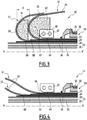
figure 3 est une vue analogue à lafigure 2 d'un premier pré-assemblage de l'embout de lafigure 2 , lors d'une étape de la méthode de montage dans laquelle les tronçons d'extrémité des nappes d'armures sont repliés vers l'arrière ; le pré-assemblage de lafigure 3 n'est pas compris par la présente invention; - la
figure 4 est une vue analogue à lafigure 3 , après dépliage des tronçons d'extrémité des nappes d'armures vers l'avant ; - la
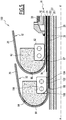
figure 5 est une vue analogue à lafigure 3 d'un pré-assemblage selon l'invention.
- the
figure 1 is a perspective view partially broken away of a flexible pipe; - the
figure 2 is a partial schematic view, taken in section along a median axial plane of the relevant elements of a nozzle of the pipe of thefigure 1 ; - the
figure 3 is a view similar to thefigure 2 of a first pre-assembly of the tip of thefigure 2 during a step of the mounting method in which the end sections of the armor plies are folded backwards; the pre-assembly of thefigure 3 is not understood by the present invention; - the
figure 4 is a view similar to thefigure 3 after unfolding the end sections of the armor plies forward; - the
figure 5 is a view similar to thefigure 3 of a pre-assembly according to the invention.
Dans tout ce qui suit, les termes « extérieur » ou « extérieurement » et « intérieur » ou « intérieurement » s'entendent généralement de manière radiale par rapport à un axe A-A' de la conduite, le terme « extérieur » s'entendant comme relativement plus éloigné radialement de l'axe A-A' et le terme « intérieur » s'entendant comme relativement plus proche radialement de l'axe A-A' de la conduite.In what follows, the terms "outside" or "externally" and "inside" or "internally" are generally understood radially in relation to an AA 'axis of conduct, the term "outside" being understood as relatively further radially from the axis AA 'and the term "inner" meaning relatively more radially closer to the axis AA' of the pipe.
Les termes « avant » et « arrière » s'entendent de manière axiale par rapport à un axe A-A' de la conduite, le terme « avant » s'entendant comme relativement plus éloigné du milieu de la conduite et plus proche d'une de ses extrémités, le terme « arrière » s'entendant comme relativement plus proche du milieu de la conduite et plus éloigné d'une de ses extrémités. Le milieu de la conduite est le point de la conduite situé à égale distance des deux extrémités de cette dernière.The terms "forward" and "rear" are axially related to an AA 'axis of the line, with the word "before" meaning relatively farther from the middle of the line and closer to one of its extremities, the term "rear" meaning relatively closer to the middle of the pipe and further away from one of its ends. The middle of the pipe is the point of the pipe situated equidistant from the two extremities of the latter.
Par ailleurs, les termes « amont » et « aval » s'entendent généralement par rapport au sens normal de circulation d'un fluide pétrolier au sein de la conduite.Moreover, the terms "upstream" and "downstream" generally refer to the normal direction of circulation of a petroleum fluid within the pipe.
Une méthode de montage n'étant pas comprise par la présente invention est mise en oeuvre lors de la fabrication d'une première conduite flexible 10, illustrée partiellement par la
La conduite flexible 10 comporte un tronçon central 12 illustré en partie sur la
La méthode est destinée au montage des embouts 14 aux extrémités du tronçon central 12.The method is intended for mounting the
En référence à la
La conduite flexible 10 est destinée à être disposée à travers une étendue d'eau (non représentée) dans une installation d'exploitation de fluide, notamment d'hydrocarbures.The
L'étendue d'eau est par exemple, une mer, un lac ou un océan. La profondeur de l'étendue d'eau au droit de l'installation d'exploitation de fluide est par exemple comprise entre 500 m et 3000 m.The body of water is, for example, a sea, a lake or an ocean. The depth of the water extent to the right of the fluid operating installation is for example between 500 m and 3000 m.
L'installation d'exploitation de fluide comporte un ensemble de surface notamment flottant et un ensemble de fond (non représentés) qui sont généralement raccordés entre eux par la conduite flexible 10.The fluid operating installation comprises a particularly floating surface assembly and a bottom assembly (not shown) which are generally connected to each other by the
La conduite flexible 10 est de préférence une conduite « non liée » (désignée par le terme anglais « unbonded »).The
Au moins deux couches adjacentes de la conduite flexible 10 sont libres de se déplacer longitudinalement l'une par rapport à l'autre lors d'une flexion de la conduite. Avantageusement, toutes les couches de la conduite flexible sont libres de se déplacer l'une par rapport à l'autre. Une telle conduite est par exemple décrite dans les documents normatifs publiés par l'American Petroleum Institute (API), API 17J, et API RP17B.At least two adjacent layers of the
Comme illustré par la
Selon l'invention, la conduite 10 comporte au moins une première gaine 20 à base de matériau polymère constituant avantageusement une gaine de pression.According to the invention, the
La conduite 10 comporte en outre une pluralité de nappes d'armures de traction 24, 25 disposées extérieurement par rapport à la première gaine 20.The
Avantageusement, et selon l'utilisation souhaitée, la conduite 10 comporte en outre une carcasse interne 26 disposée à l'intérieur de la gaine de pression 20, une voûte de pression 28 intercalée entre la gaine de pression 20 et les nappes d'armures de traction 24, 25 et une gaine externe 30, destinée à la protection de la conduite 10.Advantageously, and according to the desired use, the
Les couches 20, 26, 28 situées intérieurement par rapport aux nappes d'armures 24, 25 seront désignés par la suite par le terme « structure interne tubulaire » 31 de la conduite 10.The
De manière connue, la gaine de pression 20 est destinée à confiner de manière étanche le fluide transporté dans le passage 16. Elle est formée en matériau polymère, par exemple à base d'un polyoléfine tel que du polyéthylène, à base d'un polyamide tel que du PA11 ou du PA12, ou à base d'un polymère fluoré tel que du polyfluorure de vinylidène (PVDF).In known manner, the
L'épaisseur de la gaine de pression 20 est par exemple comprise entre 5 mm et 20 mm.The thickness of the
La carcasse 26, lorsqu'elle est présente, est formée par exemple d'un feuillard métallique profilé, enroulé en spirale. Les spires du feuillard sont avantageusement agrafées les unes aux autres, ce qui permet de reprendre les efforts radiaux d'écrasement.The
Dans cet exemple, la carcasse 26 est disposée à l'intérieur de la gaine de pression 20. La conduite est alors désignée par le terme anglais « rough bore » en raison de la géométrie de la carcasse 26In this example, the
En variante (non représentée), la conduite flexible 10 est dépourvue de carcasse interne 26, elle est alors désignée par le terme anglais « smooth bore ».Alternatively (not shown), the
L'enroulement hélicoïdal du feuillard métallique profilé formant la carcasse 26 est à pas court, c'est-à-dire qu'il présente un angle d'hélice de valeur absolue proche de 90°, typiquement compris entre 75° et 90°.The helical winding of the profiled metal strip forming the
Dans cet exemple, la voûte de pression 28 est destinée à reprendre les efforts liés à la pression régnant à l'intérieur de la gaine de pression 20. Elle est par exemple formée d'un fil profilé métallique entouré en hélice autour de la gaine 20. Le fil profilé présente généralement une géométrie complexe, notamment en forme de Z, de T, de U, de K, de X ou de I.In this example, the
La voûte de pression 28 est enroulée en hélice à pas court autour de la gaine de pression 20, c'est-à-dire avec un angle d'hélice de valeur absolue proche de 90°, typiquement compris entre 75° et 90°.The
Dans l'exemple représenté sur la
Chaque nappe d'armures 24, 25 comporte des éléments d'armure 29 longitudinaux enroulés à pas long autour de l'axe A-A' de la conduite.Each armor ply 24, 25 comprises
Par « enroulé à pas long », on entend que la valeur absolue de l'angle d'hélice est inférieure à 60°, et est typiquement comprise entre 25° et 55°.By "wrapped with a long pitch" is meant that the absolute value of the helix angle is less than 60 °, and is typically between 25 ° and 55 °.
Les éléments d'armure 29 d'une première nappe 24 sont enroulés généralement suivant un angle opposé par rapport aux éléments d'armure 29 d'une deuxième nappe 25. Ainsi, si l'angle d'enroulement des éléments d'armure 29 de la première nappe 24 est égal à + α, α étant compris entre 25° et 55°, l'angle d'enroulement des éléments d'armure 29 de la deuxième nappe 25 disposée au contact de la première nappe 24 est par exemple de - α, avec α compris entre 25° et 55°.The
Les éléments d'armure 29 sont par exemple formés par des fils métalliques, ou par des rubans.The
Comme visible sur la
Dans cet exemple, chaque nappe d'armures 24, 25 repose sur au moins une bande anti-usure 36. La bande anti-usure 36 est par exemple réalisée en plastique.In this example, each armor ply 24, 25 rests on at least one
Ainsi, une bande anti-usure 36 est intercalée entre la nappe interne 24 et la structure interne 31. Une autre bande anti-usure 36 est intercalée entre la nappe interne 24 et la nappe externe 25.Thus, an
Dans l'exemple représenté sur la
La gaine externe 30 est destinée à empêcher la perméation de fluide depuis l'extérieur de la conduite flexible vers l'intérieur. Elle est avantageusement réalisée en matériau polymère, notamment à base d'un polyoléfine, tel que du polyéthylène, à base d'un polyamide, tel que du PA11 ou du PA12, ou à base d'un polymère fluoré tel que du polyfluorure de vinylidène (PVDF).The
L'épaisseur de la gaine externe 30 est par exemple comprise entre 5 mm et 15 mm.The thickness of the
Comme illustré par la
L'embout 14 comporte en outre un ensemble avant 54 d'étanchéité autour de la gaine de pression 20, et un ensemble arrière 56 d'étanchéité autour de la gaine extérieure 30.The
L'embout 14 comprend de plus un ensemble 58 de fixation des couches d'armures 24, 25 dans la chambre 52.The
Dans cet exemple, la voûte d'extrémité 50 est destinée à raccorder la conduite 10 à un autre embout de connexion 14 ou à des équipements terminaux, avantageusement par l'intermédiaire d'une bride d'extrémité (non représentée).In this example, the
Le capot 51 délimite la chambre 52 radialement vers l'extérieur. Il couvre vers l'extérieur les tronçons d'extrémité 32 des nappes d'armures 24, 25 et s'étend axialement jusqu'à l'ensemble arrière d'étanchéité 56.The
L'ensemble avant 54 d'étanchéité comporte au moins une bague de sertissage de la gaine de pression 20. Il délimite vers l'arrière une surface inclinée 60 de guidage du décollement des tronçons d'extrémité 32 des nappes d'armures 24, 25.The
L'ensemble de fixation 58 comporte un collier de blocage arrière 62, appliqué sur la nappe externe 25 et avantageusement un matériau 70 de remplissage solide de la cavité 52, noyant les tronçons d'extrémité 32 des nappes 24, 25 et s'il est installé, le collier 62.The fixing
Le collier de blocage 62 comporte généralement une pluralité de segments périphériques assemblés les uns avec les autres. Préférentiellement, il se présente sous la forme d'un collier métallique en plusieurs parties de collier, par exemple trois parties.The locking
Les parties de collier se présentent avantageusement sous forme de segments périphériques d'étendue angulaire inférieure à 180°, assemblés les uns avec les autres pour former le collier 62.The collar portions are advantageously in the form of peripheral segments of angular extent less than 180 °, assembled with each other to form the
De manière avantageuse, le collier de blocage 62 reste à demeure autour de la nappe externe 25 mais il peut aussi être ôté avant remplissage de la chambre 52 de l'embout 14.Advantageously, the locking
Préférentiellement, un ruban ou une bande anti-usure (non représenté) est intercalée entre le collier de blocage 62 et la nappe d'armure externe 25 pour éviter tout risque de frottement et par suite, d'usure des éléments d'armure 29. Typiquement, la bande anti-usure est réalisée à partir d'au moins un polymère ou un copolymère choisi parmi les polyamides, les polyvinylidéniques, etc.Preferably, an anti-wear tape or strip (not shown) is interposed between the locking
Le collier 62 présente une surface périphérique intérieure 64 dirigée vers l'axe A-A', et appliquée sur la nappe externe 25. Il présente en outre une surface avant 66 au moins partiellement divergente vers l'avant.The
Lorsque l'embout 14 est monté, et que l'ensemble de fixation 58 est en place, chaque tronçon d'extrémité 32 d'un élément d'armure 29 décolle radialement à l'écart de l'axe A-A', à l'avant du collier de blocage 62. Chaque tronçon arrière d'un élément d'armures 29 situé à l'arrière du collier de blocage 62 s'étend sensiblement dans une enveloppe cylindrique d'axe A-A'.When the
Dans l'exemple représenté sur la
Les positions axiales de décollement 67, 68 des tronçons d'extrémité 32 respectifs de la nappe interne 24 et de la nappe externe 25 sont donc espacées axialement le long de l'axe A-A'. Ceci limite le risque de contact entre les éléments d'armures 29 respectifs, et donc le risque d'affaiblissement local de ces éléments 29.The axial detachment positions 67, 68 of the
Comme on le verra plus bas, la mise en oeuvre de la méthode de montage correspondante à la
Le pré-assemblage 80 comporte, outre la structure interne 31, les nappes d'armures 24, 25, et le collier arrière 62, un premier guide 82 de conformation du retournement de la nappe externe 25 et, un deuxième guide 84 de conformation du retournement de la nappe interne 24, décalé axialement vers l'avant par rapport au premier guide 82 et en contact avec la face interne d'au moins un élément d'armure 29.The pre-assembly 80 comprises, in addition to the
Chaque guide 82, 84 est avantageusement formé d'un matériau propre à préserver la surface des éléments d'armure 29. Par exemple, chaque guide 82, 84 est formé en une matière plastique, tel qu'un polyamide, notamment en nylon.Each
Les guides 82 et 84 comprennent une pluralité de segments périphériques assemblés les uns avec les autres ou bien sont réalisés en une seule partie.The
Leurs dimensions sont variables et sont fonction de la taille la chambre 52 et/ou de la configuration d'ancrage des nappes interne 24 et externe 25 choisie.Their dimensions are variable and are a function of the size of the
Le premier guide 82 est monté de manière amovible sur le collier arrière 62. Il définit dans cet exemple un logement axial arrière 86 d'insertion du collier arrière 62.The
Il présente une surface avant 88 incurvée et convexe, de convexité dirigée vers l'avant. La surface avant 88 est de préférence circonférentielle autour de l'axe A-A'.It has a
Avantageusement, en section dans un plan axial médian, la surface avant 88 présente un rayon de courbure inférieur au rayon de courbure minimal de chaque élément d'armure 29. Ce rayon de courbure est par exemple supérieur ou égal à 20 mm.Advantageously, in section in a median axial plane, the
Typiquement, le premier guide 82 est formé par une bague engagée autour de la nappe externe 25.Typically, the
Dans l'exemple représenté sur la
La distance d séparant axialement l'extrémité avant du premier guide 82 de l'extrémité avant du deuxième guide 84 est supérieure ou égale à la longueur cumulée du rayon de courbure de la surface avant 88, de l'épaisseur de la nappe externe 25 et de la longueur totale du deuxième guide 84.The distance d axially separating the front end of the
Le deuxième guide 84 présente une surface avant 90 incurvée et convexe, de convexité dirigée vers l'avant. La surface avant 90 est de préférence circonférentielle autour de l'axe A-A'.The
Avantageusement, En section dans un plan axial médian, la surface avant 90 présente un rayon de courbure inférieur au rayon de courbure minimal de chaque élément d'armure 29. Ce rayon de courbure est par exemple supérieur ou égal à 20 mm.Advantageously, in section in a median axial plane, the
Typiquement, le deuxième guide 84 est formé par une bague circonférentielle engagée autour de la nappe interne 24.Typically, the
Une méthode de montage de l'embout 14 selon l'invention va maintenant être décrite.A method of mounting the
Initialement, l'extrémité de la gaine externe 30 d'étanchéité du tronçon central 12 de la conduite tubulaire flexible 10 est découpée, pour dénuder les tronçons d'extrémité 32 des nappes d'armures 24, 25.Initially, the end of the
Puis, l'ensemble arrière d'étanchéité 56 est mis en place. À cet effet, une canule arrière d'appui 92 est avantageusement insérée sous l'extrémité avant de la gaine externe 30.Then, the
Ensuite, le collier arrière de blocage 62 des nappes d'armures 24, 25 est installé autour de la nappe externe 25, à l'avant de l'extrémité avant de la gaine externe 30.Then, the
Les segments du collier 62 sont disposés suivant une circonférence autour de l'axe A-A', et sont assemblés les uns aux autres. La surface interne 64 est alors appliquée extérieurement sur la nappe externe 25.The segments of the
Préférentiellement, un ruban ou une bande anti-usure (non représenté) est intercalée entre le collier de blocage 62 et la nappe d'armure externe 25 pour éviter tout risque de frottement et par suite, d'usure des éléments d'armure 29. Typiquement, la bande anti-usure est réalisée à partir d'au moins un polymère ou un copolymère choisi parmi les polyamides, les polyvinylidéniques, etc.Preferably, an anti-wear tape or strip (not shown) is interposed between the locking
Ceci étant fait, le premier guide de conformation 82 est installé sur le collier de blocage arrière 62, à l'avant de celui-ci. Dans l'exemple représenté sur la
Les tronçons d'extrémité 32 des éléments d'armure 29 de la nappe externe 25 sont alors repliés vers l'arrière autour de la surface avant 88 du premier guide 82, puis à l'extérieur radialement du premier guide 82, et du collier de blocage arrière 62.The
Ils s'appliquent sur la surface avant 88 du premier guide 82 en formant un coude à l'avant du collier de blocage arrière 62.They apply to the
Grâce au rayon de courbure relativement élevé de la surface avant 88, les tronçons d'extrémité 32 adoptent une courbure relativement faible, ce qui limite le risque d'endommagement, ou de détérioration mécanique.Due to the relatively high radius of curvature of the
L'extrémité avant de la bande anti-usure 36 située entre la nappe externe 25 et la nappe interne 24 est alors accessible.The front end of the
Une découpe d'une région avant de la bande anti-usure 36 est alors effectuée pour que le bord avant de cette bande 36 s'étende sensiblement en regard de l'extrémité avant du premier guide 82A cut of a front region of the
La longueur de bande 36 accessible est relativement importante, ce qui permet de la découper plus facilement.The
Ensuite, le deuxième guide de conformation 84 est inséré autour de la nappe interne 24, à l'avant du premier guide 82.Then, the
Les tronçons d'extrémité 32 des éléments d'armure 29 de la nappe interne 24 sont alors repliés vers l'arrière autour de la surface avant 90 du deuxième guide 84.The
Ils s'appliquent sur la surface avant 90 du deuxième guide 84 en formant un coude à l'avant du deuxième guide 84.They are applied to the
Comme précédemment, grâce au rayon de courbure relativement élevé de la surface avant 90, les tronçons d'extrémité 32 adoptent une courbure relativement faible, ce qui limite le risque d'endommagement, ou de détérioration mécanique.As before, thanks to the relatively high radius of curvature of the
Puis, la bande anti-usure 36 située entre la nappe interne 24 et la structure interne 31 est découpée. Le bord avant de cette bande 36 est alors placé sensiblement en regard de l'extrémité avant du deuxième guide 90, à l'écart axialement du bord avant de la bande 36 située entre les nappes 24, 25.Then, the
L'ensemble avant d'étanchéité 54 est alors mis en place, à l'avant du premier guide 84, avec l'engagement de la bague de sertissage autour de la structure interne 31.The
L'extrémité de la voûte 28 se trouve ainsi insérée intérieurement à la bague de sertissage.The end of the arch 28 is thus inserted internally to the crimping ring.
La gaine de pression 20 est ensuite sertie par la bague de sertissage, ainsi que la voûte de pression 28, lorsqu'elle est présente.The
Ceci étant fait, les tronçons d'extrémité 32 des éléments d'armure 29 de la nappe interne 24 sont dépliés vers l'avant pour reposer au niveau de la voûte 28 et le deuxième guide 84 est ensuite retiré.This being done, the
De même, et de manière séparée, les tronçons d'extrémité 32 des éléments d'armure 29 de la nappe externe 25 sont dépliés vers l'avant pour reposer au niveau de la nappe d'armure interne 24 et le premier guide 82 est ensuite retiré.Similarly, and separately, the
Les positions axiales 67, 68 de décollement des tronçons d'extrémité 32 respectifs de la nappe interne 24 et de la nappe externe 25 étant décalées le long de l'axe A-A', les tronçons d'extrémité 32 des éléments d'armure 29 n'entrent pas en contact les uns avec les autres lorsqu'ils sont dépliés vers l'avant.The
Ainsi, le risque de frottement et de détérioration entre les éléments d'armure 29 des deux nappes 24, 25 est réduit. Le comportement en fatigue des nappes d'armures 24, 25 est alors grandement amélioré, ce qui augmente l'intégrité de la conduite flexible 10 dans le temps.Thus, the risk of friction and deterioration between the
Puis, le capot 51 est mis en place autour des tronçons d'extrémité 32 et est fixé sur la voûte 50. Un matériau fluide propre à se solidifier est alors avantageusement introduit dans la chambre 52 pour noyer les tronçons d'extrémité 32 et le collier arrière 62.Then, the
Un pré-assemblage 100 selon l'invention est illustré par la
À la différence du premier pré-assemblage 80, le deuxième pré-assemblage 100, qui correspond à la présente invention, comporte un collier avant de blocage 102. Ce collier 102 est de préférence en métal.Unlike the first pre-assembly 80, the second pre-assembly 100, which corresponds to the present invention, comprises a locking
Le collier avant de blocage 102 est monté autour de la nappe interne 24, intérieurement par rapport à la nappe externe 25, à l'avant du premier guide 82.The locking
Le collier avant 102 comporte avantageusement une pluralité de segments périphériques assemblés les uns avec les autres. Comme le collier arrière 62, il peut rester à demeure autour de la nappe interne 24 mais il peut aussi être ôté avant remplissage de la chambre 52 de l'embout 14.The
Il présente une surface périphérique intérieure 104 dirigée vers l'axe A-A', et appliquée sur la nappe externe 25.It has an inner
Comme décrit plus haut par rapport au collier arrière 62, un ruban ou une bande anti-usure (non représenté) est intercalée entre le collier de blocage 102 et la nappe d'armure interne 24 pour éviter tout risque de frottement et par suite, d'usure des éléments d'armure 29.As described above with respect to the
Il présente en outre une surface avant 106 au moins partiellement divergente vers l'avant pour limiter le décollement des tronçons d'extrémité 32 de la nappe d'armures interne 24.It further has a
Le deuxième guide 84 est monté de manière amovible sur le collier avant 102. Il définit dans cet exemple un logement axial arrière 108 d'insertion du collier avant 102.The
Le procédé de montage selon l'invention diffère du procédé de montage correspondant à la
Le deuxième guide 84 est alors monté sur le collier avant 102. Les tronçons d'extrémité 32 des éléments d'armure 29 de la nappe interne 24 sont ensuite repliés autour de la surface avant 90 du deuxième guide 84, puis à l'extérieur radialement du deuxième guide 84, et du collier avant 102.The
La méthode de montage correspondante à la
Claims (12)
- A method for assembling an end-piece (14) of a flexible pipe (10), the flexible pipe (10) including an inner tubular structure (31) having a central axis (A-A'), an inner ply (24) of tensile armors positioned around the inner tubular structure (31) and an outer ply (25) of tensile armors positioned around the inner ply (24), the method comprising the following steps:- placing a rear locking collar (62) of the armor plies (24, 25) around the outer ply (25);- placing a first shaping guide (82) for shaping the folding of the end segments (32) of the outer ply (25);- folding the end segments (32) of the outer ply (25) rearwards while forming a bend in front of the locking collar (62), the end segments (32) of the outer ply (25) pressing on the first guide (82);- folding the end segments (32) of the inner ply (24) rearwards;characterized in that it includes, before the step for folding the end segments (32) of the inner ply (24) rearwards, the placement of a second shaping guide (84) for shaping the folding of the end segments (32) of the inner ply (24), the second shaping guide (84) being separate from the first shaping guide (82), the end segments (32) of the inner ply (24) bearing on the second shaping guide (84) after the folding step,
and in that it includes, after the folding steps, the following steps:- inserting a front sealing assembly (54) around the inner tubular structure (31);- placing a vault (50) of the end-piece in the end of the inner tubular structure (31);- folding the end segments (32) of the inner ply (24) forward to place them around the vault (50);- removing the second shaping guide (84);- folding the end segments (32) of the outer ply (25) forward to place them outwardly at the end segments of the inner ply (24);- removing the first shaping guide (82); and- fastening an outer cover (51) of the end-piece on the vault (50), the vault (50) and the outer cover (51) delimiting a chamber (52) between them for receiving the end segments (32) of the inner ply (24) and the outer ply (25) ;in that the step for placing the second shaping guide (84) is carried out after the rearward folding of the end segments (32) of the outer ply (25) around the first shaping guide (82), and before the rearward folding of the end segments (32) toward the inner ply (24) ;
and in that the placement of the second shaping guide (84) includes the arrangement, around the inner ply (24), of a front locking collar (102) of the inner ply (24), the second shaping guide (84) being placed on the front locking collar (102). - The method according to claim 1, characterized in that after the folding steps, the end segments (32) of the outer ply (25) separate from the inner ply (24) in a first axial position (67) along the central axis, the end segments (32) of the inner ply (24) separating from the inner tubular structure (31) in a second axial position (68), axially offset from the first axial position (67).
- The method according to claim 1 or 2, characterized in that the second shaping guide (84) is positioned in front of the bend formed by the end segments (32) of the outer ply (25) during its placement.
- The method according to any one of the preceding claims, characterized in that it includes, after the folding of the end segments (32) of the outer ply (25), and before the placement of the second shaping guide (84), cutting an anti-wear strip (36) positioned between the inner ply (24) and the outer ply (25).
- The method according to any one of the preceding claims, characterized in that it includes a step for removing the front collar (102), after having removed the second shaping guide (84) and before folding the end segments (32) of the inner ply (24) forward to place them around the vault (50).
- The method according to any one of the preceding claims, characterized in that it includes a second step for removing the rear collar (62), after having removed the first shaping guide (82) and before folding the end segments (32) of the inner ply (25) forward to place them outside the end segments of the inner ply (24).
- The method according to any one of the preceding claims, characterized in that it includes inserting a filler material (70) able to solidify in the receiving chamber (52).
- The method according to any one of the preceding claims, characterized in that the first guide (82) and the second guide (84) each have a convex front surface (88, 90), with the convex side oriented forward, the respective end segments (32) of the outer ply (25) and the inner ply (24) each bearing on a respective front surface (88, 90) of the first guide (82) and the second guide (84).
- A pre-assembly (80; 100) of a flexible pipe (10) end-piece (14), the flexible pipe (10) including an inner tubular structure (31) having a central axis (A-A'), an inner ply (24) of tensile armors positioned around the inner tubular structure (31) and an outer ply (25) of tensile armors positioned around the inner structure (24),
the pre-assembly (80; 100) including:- a rear locking collar (62) of the armor plies (24, 25) placed around the outer ply (25);- a first shaping guide (82) for the folding of the end segments (32) of the outer ply (25), the end segments (32) of the outer ply (25) bearing on the first guide (82) while forming a bend in front of the rear locking collar (62);characterized in that it includes a second shaping guide (84) for shaping the folding of the end segments (32) of the inner ply (24), separate from the first shaping guide (82), the end segments (32) of the inner ply (24) bearing on the second guide (84) while forming a bend in front of the rear locking collar (62), and in that it includes a front locking collar (102) of the inner ply (24), the second shaping guide (84) being placed on the front locking collar (102). - A pre-assembly (80; 100) according to claim 9, characterized in that the end segments (32) of the outer ply (25) separate from the inner ply (24) in a first axial position (67) along the central axis (A-A'), the end segments (32) of the inner ply (24) separating from the inner tubular structure (31) in a second axial position (68), axially offset from the first axial position (67).
- The pre-assembly (80; 100) according to any one of claims 9 to 10, characterized in that it includes an anti-wear strip (36) positioned between the inner ply (24) and the outer ply (25), the anti-wear strip (36) having a front edge situated between the first guide (82) and the second guide (84).
- The pre-assembly (80; 100) according to any one of claims 9 to 11, characterized in that the first guide (82) and the second guide (84) each have a convex front surface (88, 90), with the convex side oriented forward, the respective end segments (32) of the outer ply (25) and the inner ply (24) each bearing on a respective front surface (88, 90) of the first guide (82) and the second guide (84).
Applications Claiming Priority (2)
| Application Number | Priority Date | Filing Date | Title |
|---|---|---|---|
| FR1352041A FR3003003B1 (en) | 2013-03-07 | 2013-03-07 | METHOD OF MOUNTING A FLEXIBLE DRIVING TIP AND PRE-ASSEMBLY THEREFOR |
| PCT/EP2014/054301 WO2014135612A1 (en) | 2013-03-07 | 2014-03-06 | Method for assembling an end-piece of a flexible pipe and associated pre-assembly |
Publications (2)
| Publication Number | Publication Date |
|---|---|
| EP2964991A1 EP2964991A1 (en) | 2016-01-13 |
| EP2964991B1 true EP2964991B1 (en) | 2017-09-13 |
Family
ID=48407715
Family Applications (1)
| Application Number | Title | Priority Date | Filing Date |
|---|---|---|---|
| EP14708035.2A Active EP2964991B1 (en) | 2013-03-07 | 2014-03-06 | Method for assembling an end-piece of a flexible pipe and associated pre-assembly |
Country Status (9)
| Country | Link |
|---|---|
| US (1) | US10053267B2 (en) |
| EP (1) | EP2964991B1 (en) |
| AP (1) | AP2015008738A0 (en) |
| AU (1) | AU2014224609B2 (en) |
| BR (1) | BR112015021657B1 (en) |
| DK (1) | DK2964991T3 (en) |
| FR (1) | FR3003003B1 (en) |
| MY (1) | MY170038A (en) |
| WO (1) | WO2014135612A1 (en) |
Families Citing this family (4)
| Publication number | Priority date | Publication date | Assignee | Title |
|---|---|---|---|---|
| FR3000170B1 (en) * | 2012-12-21 | 2016-04-29 | Technip France | CONNECTING TIP FOR A FLEXIBLE FLUID TRANSPORT DUCT AND ASSOCIATED METHOD |
| GB201306823D0 (en) * | 2013-04-15 | 2013-05-29 | Wellstream Int Ltd | Flexible pipe components and method of manufacture of flexible pipe |
| FR3035171B1 (en) * | 2015-04-20 | 2017-05-19 | Technip France | METHOD OF MAKING SEALING INTO A TIP OF A FLEXIBLE CONDUIT COMPRISING A PRESSURE SLEEVE |
| FR3052530B1 (en) * | 2016-06-13 | 2019-05-31 | Technip France | FLEXIBLE LINE CONNECTION TIP, FLEXIBLE LINE AND METHOD THEREOF |
Family Cites Families (9)
| Publication number | Priority date | Publication date | Assignee | Title |
|---|---|---|---|---|
| JPS60215190A (en) * | 1984-04-09 | 1985-10-28 | 古河電気工業株式会社 | Terminal fitting for high-pressure fluid transport pipe |
| JPH0633841B2 (en) * | 1985-10-29 | 1994-05-02 | 古河電気工業株式会社 | Assembly method of terminal fitting for flexible fluid transportation pipe |
| JPH0633842B2 (en) * | 1985-11-12 | 1994-05-02 | 古河電気工業株式会社 | Assembly method of terminal fittings for fluid transportation pipe |
| JP2533941B2 (en) | 1989-07-05 | 1996-09-11 | 川崎重工業株式会社 | Hydrofoil test equipment |
| JPH0736228Y2 (en) * | 1989-08-24 | 1995-08-16 | 古河電気工業株式会社 | Fluid transport pipe terminal fittings |
| JPH04171390A (en) * | 1990-11-01 | 1992-06-18 | Furukawa Electric Co Ltd:The | Terminal metal fitting for fluid transporting pipe |
| JPH05231576A (en) * | 1992-02-14 | 1993-09-07 | Furukawa Electric Co Ltd:The | Terminal fitting of fluid transport tube |
| FR2816389B1 (en) * | 2000-11-08 | 2003-05-30 | Coflexip | FLEXIBLE CONDUIT TIP |
| FR2827032B1 (en) * | 2001-07-05 | 2003-09-05 | Coflexip | NOZZLE FOR FLEXIBLE DUCT WITHOUT PRESSURE VANE AND MANUFACTURING METHOD THEREOF |
-
2013
- 2013-03-07 FR FR1352041A patent/FR3003003B1/en not_active Expired - Fee Related
-
2014
- 2014-03-06 DK DK14708035.2T patent/DK2964991T3/en active
- 2014-03-06 BR BR112015021657-9A patent/BR112015021657B1/en active IP Right Grant
- 2014-03-06 US US14/772,906 patent/US10053267B2/en not_active Expired - Fee Related
- 2014-03-06 WO PCT/EP2014/054301 patent/WO2014135612A1/en active Application Filing
- 2014-03-06 MY MYPI2015002204A patent/MY170038A/en unknown
- 2014-03-06 AP AP2015008738A patent/AP2015008738A0/en unknown
- 2014-03-06 EP EP14708035.2A patent/EP2964991B1/en active Active
- 2014-03-06 AU AU2014224609A patent/AU2014224609B2/en active Active
Non-Patent Citations (1)
| Title |
|---|
| None * |
Also Published As
| Publication number | Publication date |
|---|---|
| AU2014224609A1 (en) | 2015-09-24 |
| BR112015021657B1 (en) | 2021-04-27 |
| AP2015008738A0 (en) | 2015-09-30 |
| AU2014224609B2 (en) | 2018-03-01 |
| DK2964991T3 (en) | 2018-01-02 |
| MY170038A (en) | 2019-06-26 |
| US10053267B2 (en) | 2018-08-21 |
| US20160016708A1 (en) | 2016-01-21 |
| FR3003003B1 (en) | 2016-02-12 |
| WO2014135612A1 (en) | 2014-09-12 |
| EP2964991A1 (en) | 2016-01-13 |
| BR112015021657A2 (en) | 2017-07-18 |
| FR3003003A1 (en) | 2014-09-12 |
Similar Documents
| Publication | Publication Date | Title |
|---|---|---|
| EP3014157B1 (en) | Flexible pipe and method | |
| EP3469244B1 (en) | Connection end piece for a flexible line, and associated flexible line and method | |
| EP2935965B1 (en) | Connection end-piece of a flexible pipe for transporting fluid and associated method | |
| EP3286474B1 (en) | Method for forming a seal in an end fitting of a flexible conduit including a pressure sheath | |
| EP3717817B1 (en) | Connection end-piece for a flexible pipe for transporting fluid, associated pipe and method | |
| EP3017229B1 (en) | Flexible pipe comprising connection end-piece with a spacing member and associated mounting method | |
| FR3038033A1 (en) | METHOD OF MOUNTING FLEXIBLE DRIVING TIP | |
| WO2000022337A1 (en) | Flexible conduit with high inertia hoop | |
| EP2689175B1 (en) | Assembly of a connection end fitting and a flexible tubular pipe for carrying a fluid in a marine environment and method for fitting said connection end fitting | |
| EP3397886B1 (en) | Connection tip for a flexible line, and associated flexible line and mounting method | |
| EP2964991B1 (en) | Method for assembling an end-piece of a flexible pipe and associated pre-assembly | |
| EP2989366A1 (en) | Method for producing a connection end piece of a flexible pipe and related end piece | |
| WO2015007854A1 (en) | Connection end piece of a flexible pipe, and associated flexible pipe | |
| WO2017097931A1 (en) | Connection fitting for a flexible pipe and associated assembly method | |
| OA17482A (en) | Method of mounting a flexible pipe end piece and associated pre-assembly. | |
| EP4013984B1 (en) | Connection tip for a flexible pipe, associated flexible pipe and mounting method |
Legal Events
| Date | Code | Title | Description |
|---|---|---|---|
| PUAI | Public reference made under article 153(3) epc to a published international application that has entered the european phase |
Free format text: ORIGINAL CODE: 0009012 |
|
| 17P | Request for examination filed |
Effective date: 20150904 |
|
| AK | Designated contracting states |
Kind code of ref document: A1 Designated state(s): AL AT BE BG CH CY CZ DE DK EE ES FI FR GB GR HR HU IE IS IT LI LT LU LV MC MK MT NL NO PL PT RO RS SE SI SK SM TR |
|
| AX | Request for extension of the european patent |
Extension state: BA ME |
|
| DAX | Request for extension of the european patent (deleted) | ||
| REG | Reference to a national code |
Ref country code: DE Ref legal event code: R079 Ref document number: 602014014518 Country of ref document: DE Free format text: PREVIOUS MAIN CLASS: F16L0033010000 Ipc: B65D0059060000 |
|
| GRAP | Despatch of communication of intention to grant a patent |
Free format text: ORIGINAL CODE: EPIDOSNIGR1 |
|
| RIC1 | Information provided on ipc code assigned before grant |
Ipc: F16L 33/01 20060101ALI20170315BHEP Ipc: B65D 59/06 20060101AFI20170315BHEP |
|
| INTG | Intention to grant announced |
Effective date: 20170410 |
|
| GRAS | Grant fee paid |
Free format text: ORIGINAL CODE: EPIDOSNIGR3 |
|
| GRAA | (expected) grant |
Free format text: ORIGINAL CODE: 0009210 |
|
| AK | Designated contracting states |
Kind code of ref document: B1 Designated state(s): AL AT BE BG CH CY CZ DE DK EE ES FI FR GB GR HR HU IE IS IT LI LT LU LV MC MK MT NL NO PL PT RO RS SE SI SK SM TR |
|
| REG | Reference to a national code |
Ref country code: GB Ref legal event code: FG4D Free format text: NOT ENGLISH |
|
| REG | Reference to a national code |
Ref country code: CH Ref legal event code: EP |
|
| REG | Reference to a national code |
Ref country code: IE Ref legal event code: FG4D Free format text: LANGUAGE OF EP DOCUMENT: FRENCH |
|
| REG | Reference to a national code |
Ref country code: AT Ref legal event code: REF Ref document number: 927891 Country of ref document: AT Kind code of ref document: T Effective date: 20171015 |
|
| REG | Reference to a national code |
Ref country code: DE Ref legal event code: R096 Ref document number: 602014014518 Country of ref document: DE |
|
| REG | Reference to a national code |
Ref country code: NO Ref legal event code: T2 Effective date: 20170913 |
|
| REG | Reference to a national code |
Ref country code: DK Ref legal event code: T3 Effective date: 20171219 |
|
| REG | Reference to a national code |
Ref country code: NL Ref legal event code: MP Effective date: 20170913 |
|
| REG | Reference to a national code |
Ref country code: LT Ref legal event code: MG4D |
|
| PG25 | Lapsed in a contracting state [announced via postgrant information from national office to epo] |
Ref country code: SE Free format text: LAPSE BECAUSE OF FAILURE TO SUBMIT A TRANSLATION OF THE DESCRIPTION OR TO PAY THE FEE WITHIN THE PRESCRIBED TIME-LIMIT Effective date: 20170913 Ref country code: HR Free format text: LAPSE BECAUSE OF FAILURE TO SUBMIT A TRANSLATION OF THE DESCRIPTION OR TO PAY THE FEE WITHIN THE PRESCRIBED TIME-LIMIT Effective date: 20170913 Ref country code: LT Free format text: LAPSE BECAUSE OF FAILURE TO SUBMIT A TRANSLATION OF THE DESCRIPTION OR TO PAY THE FEE WITHIN THE PRESCRIBED TIME-LIMIT Effective date: 20170913 Ref country code: FI Free format text: LAPSE BECAUSE OF FAILURE TO SUBMIT A TRANSLATION OF THE DESCRIPTION OR TO PAY THE FEE WITHIN THE PRESCRIBED TIME-LIMIT Effective date: 20170913 |
|
| REG | Reference to a national code |
Ref country code: AT Ref legal event code: MK05 Ref document number: 927891 Country of ref document: AT Kind code of ref document: T Effective date: 20170913 |
|
| PG25 | Lapsed in a contracting state [announced via postgrant information from national office to epo] |
Ref country code: LV Free format text: LAPSE BECAUSE OF FAILURE TO SUBMIT A TRANSLATION OF THE DESCRIPTION OR TO PAY THE FEE WITHIN THE PRESCRIBED TIME-LIMIT Effective date: 20170913 Ref country code: ES Free format text: LAPSE BECAUSE OF FAILURE TO SUBMIT A TRANSLATION OF THE DESCRIPTION OR TO PAY THE FEE WITHIN THE PRESCRIBED TIME-LIMIT Effective date: 20170913 Ref country code: BG Free format text: LAPSE BECAUSE OF FAILURE TO SUBMIT A TRANSLATION OF THE DESCRIPTION OR TO PAY THE FEE WITHIN THE PRESCRIBED TIME-LIMIT Effective date: 20171213 Ref country code: RS Free format text: LAPSE BECAUSE OF FAILURE TO SUBMIT A TRANSLATION OF THE DESCRIPTION OR TO PAY THE FEE WITHIN THE PRESCRIBED TIME-LIMIT Effective date: 20170913 Ref country code: GR Free format text: LAPSE BECAUSE OF FAILURE TO SUBMIT A TRANSLATION OF THE DESCRIPTION OR TO PAY THE FEE WITHIN THE PRESCRIBED TIME-LIMIT Effective date: 20171214 |
|
| PG25 | Lapsed in a contracting state [announced via postgrant information from national office to epo] |
Ref country code: NL Free format text: LAPSE BECAUSE OF FAILURE TO SUBMIT A TRANSLATION OF THE DESCRIPTION OR TO PAY THE FEE WITHIN THE PRESCRIBED TIME-LIMIT Effective date: 20170913 |
|
| REG | Reference to a national code |
Ref country code: FR Ref legal event code: PLFP Year of fee payment: 5 |
|
| PG25 | Lapsed in a contracting state [announced via postgrant information from national office to epo] |
Ref country code: CZ Free format text: LAPSE BECAUSE OF FAILURE TO SUBMIT A TRANSLATION OF THE DESCRIPTION OR TO PAY THE FEE WITHIN THE PRESCRIBED TIME-LIMIT Effective date: 20170913 Ref country code: PL Free format text: LAPSE BECAUSE OF FAILURE TO SUBMIT A TRANSLATION OF THE DESCRIPTION OR TO PAY THE FEE WITHIN THE PRESCRIBED TIME-LIMIT Effective date: 20170913 Ref country code: RO Free format text: LAPSE BECAUSE OF FAILURE TO SUBMIT A TRANSLATION OF THE DESCRIPTION OR TO PAY THE FEE WITHIN THE PRESCRIBED TIME-LIMIT Effective date: 20170913 |
|
| PG25 | Lapsed in a contracting state [announced via postgrant information from national office to epo] |
Ref country code: SM Free format text: LAPSE BECAUSE OF FAILURE TO SUBMIT A TRANSLATION OF THE DESCRIPTION OR TO PAY THE FEE WITHIN THE PRESCRIBED TIME-LIMIT Effective date: 20170913 Ref country code: SK Free format text: LAPSE BECAUSE OF FAILURE TO SUBMIT A TRANSLATION OF THE DESCRIPTION OR TO PAY THE FEE WITHIN THE PRESCRIBED TIME-LIMIT Effective date: 20170913 Ref country code: IT Free format text: LAPSE BECAUSE OF FAILURE TO SUBMIT A TRANSLATION OF THE DESCRIPTION OR TO PAY THE FEE WITHIN THE PRESCRIBED TIME-LIMIT Effective date: 20170913 Ref country code: AT Free format text: LAPSE BECAUSE OF FAILURE TO SUBMIT A TRANSLATION OF THE DESCRIPTION OR TO PAY THE FEE WITHIN THE PRESCRIBED TIME-LIMIT Effective date: 20170913 Ref country code: IS Free format text: LAPSE BECAUSE OF FAILURE TO SUBMIT A TRANSLATION OF THE DESCRIPTION OR TO PAY THE FEE WITHIN THE PRESCRIBED TIME-LIMIT Effective date: 20180113 Ref country code: EE Free format text: LAPSE BECAUSE OF FAILURE TO SUBMIT A TRANSLATION OF THE DESCRIPTION OR TO PAY THE FEE WITHIN THE PRESCRIBED TIME-LIMIT Effective date: 20170913 |
|
| REG | Reference to a national code |
Ref country code: DE Ref legal event code: R097 Ref document number: 602014014518 Country of ref document: DE |
|
| PLBE | No opposition filed within time limit |
Free format text: ORIGINAL CODE: 0009261 |
|
| STAA | Information on the status of an ep patent application or granted ep patent |
Free format text: STATUS: NO OPPOSITION FILED WITHIN TIME LIMIT |
|
| 26N | No opposition filed |
Effective date: 20180614 |
|
| PG25 | Lapsed in a contracting state [announced via postgrant information from national office to epo] |
Ref country code: MT Free format text: LAPSE BECAUSE OF FAILURE TO SUBMIT A TRANSLATION OF THE DESCRIPTION OR TO PAY THE FEE WITHIN THE PRESCRIBED TIME-LIMIT Effective date: 20170913 |
|
| REG | Reference to a national code |
Ref country code: DE Ref legal event code: R119 Ref document number: 602014014518 Country of ref document: DE |
|
| REG | Reference to a national code |
Ref country code: CH Ref legal event code: PL |
|
| PG25 | Lapsed in a contracting state [announced via postgrant information from national office to epo] |
Ref country code: SI Free format text: LAPSE BECAUSE OF FAILURE TO SUBMIT A TRANSLATION OF THE DESCRIPTION OR TO PAY THE FEE WITHIN THE PRESCRIBED TIME-LIMIT Effective date: 20170913 Ref country code: MC Free format text: LAPSE BECAUSE OF FAILURE TO SUBMIT A TRANSLATION OF THE DESCRIPTION OR TO PAY THE FEE WITHIN THE PRESCRIBED TIME-LIMIT Effective date: 20170913 |
|
| REG | Reference to a national code |
Ref country code: BE Ref legal event code: MM Effective date: 20180331 |
|
| REG | Reference to a national code |
Ref country code: IE Ref legal event code: MM4A |
|
| PG25 | Lapsed in a contracting state [announced via postgrant information from national office to epo] |
Ref country code: LU Free format text: LAPSE BECAUSE OF NON-PAYMENT OF DUE FEES Effective date: 20180306 |
|
| PG25 | Lapsed in a contracting state [announced via postgrant information from national office to epo] |
Ref country code: DE Free format text: LAPSE BECAUSE OF NON-PAYMENT OF DUE FEES Effective date: 20181002 Ref country code: IE Free format text: LAPSE BECAUSE OF NON-PAYMENT OF DUE FEES Effective date: 20180306 |
|
| PG25 | Lapsed in a contracting state [announced via postgrant information from national office to epo] |
Ref country code: BE Free format text: LAPSE BECAUSE OF NON-PAYMENT OF DUE FEES Effective date: 20180331 Ref country code: LI Free format text: LAPSE BECAUSE OF NON-PAYMENT OF DUE FEES Effective date: 20180331 Ref country code: CH Free format text: LAPSE BECAUSE OF NON-PAYMENT OF DUE FEES Effective date: 20180331 |
|
| PG25 | Lapsed in a contracting state [announced via postgrant information from national office to epo] |
Ref country code: TR Free format text: LAPSE BECAUSE OF FAILURE TO SUBMIT A TRANSLATION OF THE DESCRIPTION OR TO PAY THE FEE WITHIN THE PRESCRIBED TIME-LIMIT Effective date: 20170913 |
|
| PG25 | Lapsed in a contracting state [announced via postgrant information from national office to epo] |
Ref country code: PT Free format text: LAPSE BECAUSE OF FAILURE TO SUBMIT A TRANSLATION OF THE DESCRIPTION OR TO PAY THE FEE WITHIN THE PRESCRIBED TIME-LIMIT Effective date: 20170913 |
|
| PG25 | Lapsed in a contracting state [announced via postgrant information from national office to epo] |
Ref country code: HU Free format text: LAPSE BECAUSE OF FAILURE TO SUBMIT A TRANSLATION OF THE DESCRIPTION OR TO PAY THE FEE WITHIN THE PRESCRIBED TIME-LIMIT; INVALID AB INITIO Effective date: 20140306 Ref country code: CY Free format text: LAPSE BECAUSE OF FAILURE TO SUBMIT A TRANSLATION OF THE DESCRIPTION OR TO PAY THE FEE WITHIN THE PRESCRIBED TIME-LIMIT Effective date: 20170913 Ref country code: MK Free format text: LAPSE BECAUSE OF NON-PAYMENT OF DUE FEES Effective date: 20170913 |
|
| PG25 | Lapsed in a contracting state [announced via postgrant information from national office to epo] |
Ref country code: AL Free format text: LAPSE BECAUSE OF FAILURE TO SUBMIT A TRANSLATION OF THE DESCRIPTION OR TO PAY THE FEE WITHIN THE PRESCRIBED TIME-LIMIT Effective date: 20170913 |
|
| PGFP | Annual fee paid to national office [announced via postgrant information from national office to epo] |
Ref country code: NO Payment date: 20230223 Year of fee payment: 10 Ref country code: FR Payment date: 20230330 Year of fee payment: 10 Ref country code: DK Payment date: 20230227 Year of fee payment: 10 |
|
| PGFP | Annual fee paid to national office [announced via postgrant information from national office to epo] |
Ref country code: GB Payment date: 20230324 Year of fee payment: 10 |
|
| P01 | Opt-out of the competence of the unified patent court (upc) registered |
Effective date: 20230516 |