EP3610185B1 - Verfahren zum befestigen eines verankerungselements an einem element der panzerung eines flexiblen rohrs, zugehöriges rohr und zugehöriges montageverfahren - Google Patents
Verfahren zum befestigen eines verankerungselements an einem element der panzerung eines flexiblen rohrs, zugehöriges rohr und zugehöriges montageverfahren Download PDFInfo
- Publication number
- EP3610185B1 EP3610185B1 EP18716291.2A EP18716291A EP3610185B1 EP 3610185 B1 EP3610185 B1 EP 3610185B1 EP 18716291 A EP18716291 A EP 18716291A EP 3610185 B1 EP3610185 B1 EP 3610185B1
- Authority
- EP
- European Patent Office
- Prior art keywords
- armor
- anchorage
- elements
- pipe
- armor element
- Prior art date
- Legal status (The legal status is an assumption and is not a legal conclusion. Google has not performed a legal analysis and makes no representation as to the accuracy of the status listed.)
- Active
Links
- 238000000034 method Methods 0.000 title claims description 57
- 239000000463 material Substances 0.000 claims description 22
- 238000002844 melting Methods 0.000 claims description 15
- 230000008018 melting Effects 0.000 claims description 15
- 238000010438 heat treatment Methods 0.000 claims description 13
- 230000007935 neutral effect Effects 0.000 claims description 13
- 230000015572 biosynthetic process Effects 0.000 claims description 12
- 238000010891 electric arc Methods 0.000 claims description 11
- 238000005242 forging Methods 0.000 claims description 11
- 239000000945 filler Substances 0.000 claims description 6
- 229910000831 Steel Inorganic materials 0.000 claims description 5
- 239000010959 steel Substances 0.000 claims description 5
- 230000037452 priming Effects 0.000 claims 2
- 238000004873 anchoring Methods 0.000 description 101
- 230000004927 fusion Effects 0.000 description 21
- 239000012530 fluid Substances 0.000 description 12
- 238000009792 diffusion process Methods 0.000 description 10
- XLYOFNOQVPJJNP-UHFFFAOYSA-N water Substances O XLYOFNOQVPJJNP-UHFFFAOYSA-N 0.000 description 10
- 238000007789 sealing Methods 0.000 description 9
- 229910052751 metal Inorganic materials 0.000 description 8
- 239000002184 metal Substances 0.000 description 7
- 238000003466 welding Methods 0.000 description 7
- 238000007711 solidification Methods 0.000 description 5
- 230000008023 solidification Effects 0.000 description 5
- 238000004804 winding Methods 0.000 description 5
- 229920001774 Perfluoroether Polymers 0.000 description 4
- 238000009434 installation Methods 0.000 description 4
- -1 polyethylene Polymers 0.000 description 4
- 239000002033 PVDF binder Substances 0.000 description 3
- 238000002788 crimping Methods 0.000 description 3
- 230000000694 effects Effects 0.000 description 3
- 238000007667 floating Methods 0.000 description 3
- 230000000977 initiatory effect Effects 0.000 description 3
- 239000003208 petroleum Substances 0.000 description 3
- 239000002861 polymer material Substances 0.000 description 3
- 229920002981 polyvinylidene fluoride Polymers 0.000 description 3
- 239000004696 Poly ether ether ketone Substances 0.000 description 2
- 239000004952 Polyamide Substances 0.000 description 2
- 239000004698 Polyethylene Substances 0.000 description 2
- 239000004642 Polyimide Substances 0.000 description 2
- 239000004743 Polypropylene Substances 0.000 description 2
- 229920002313 fluoropolymer Polymers 0.000 description 2
- 239000004811 fluoropolymer Substances 0.000 description 2
- 229930195733 hydrocarbon Natural products 0.000 description 2
- 150000002430 hydrocarbons Chemical class 0.000 description 2
- 230000014759 maintenance of location Effects 0.000 description 2
- 230000002093 peripheral effect Effects 0.000 description 2
- 229920002492 poly(sulfone) Polymers 0.000 description 2
- 229920002647 polyamide Polymers 0.000 description 2
- 229920002530 polyetherether ketone Polymers 0.000 description 2
- 229920000573 polyethylene Polymers 0.000 description 2
- 229920001721 polyimide Polymers 0.000 description 2
- 229920000098 polyolefin Polymers 0.000 description 2
- 229920000069 polyphenylene sulfide Polymers 0.000 description 2
- 229920001155 polypropylene Polymers 0.000 description 2
- 229920001187 thermosetting polymer Polymers 0.000 description 2
- 230000001960 triggered effect Effects 0.000 description 2
- 229920000049 Carbon (fiber) Polymers 0.000 description 1
- 239000004593 Epoxy Substances 0.000 description 1
- 238000006424 Flood reaction Methods 0.000 description 1
- 238000003723 Smelting Methods 0.000 description 1
- 241000722921 Tulipa gesneriana Species 0.000 description 1
- 238000013019 agitation Methods 0.000 description 1
- 238000000137 annealing Methods 0.000 description 1
- 230000000712 assembly Effects 0.000 description 1
- 238000000429 assembly Methods 0.000 description 1
- 238000005452 bending Methods 0.000 description 1
- 239000004917 carbon fiber Substances 0.000 description 1
- 239000002131 composite material Substances 0.000 description 1
- 238000005336 cracking Methods 0.000 description 1
- 238000005520 cutting process Methods 0.000 description 1
- 125000002573 ethenylidene group Chemical group [*]=C=C([H])[H] 0.000 description 1
- 238000002347 injection Methods 0.000 description 1
- 239000007924 injection Substances 0.000 description 1
- 230000003993 interaction Effects 0.000 description 1
- 238000002955 isolation Methods 0.000 description 1
- 238000004519 manufacturing process Methods 0.000 description 1
- 239000002952 polymeric resin Substances 0.000 description 1
- 239000011819 refractory material Substances 0.000 description 1
- 229920005989 resin Polymers 0.000 description 1
- 239000011347 resin Substances 0.000 description 1
- 238000004904 shortening Methods 0.000 description 1
- 239000007787 solid Substances 0.000 description 1
- 230000000638 stimulation Effects 0.000 description 1
- 229920003002 synthetic resin Polymers 0.000 description 1
- 238000011144 upstream manufacturing Methods 0.000 description 1
Images


Classifications
-
- F—MECHANICAL ENGINEERING; LIGHTING; HEATING; WEAPONS; BLASTING
- F16—ENGINEERING ELEMENTS AND UNITS; GENERAL MEASURES FOR PRODUCING AND MAINTAINING EFFECTIVE FUNCTIONING OF MACHINES OR INSTALLATIONS; THERMAL INSULATION IN GENERAL
- F16L—PIPES; JOINTS OR FITTINGS FOR PIPES; SUPPORTS FOR PIPES, CABLES OR PROTECTIVE TUBING; MEANS FOR THERMAL INSULATION IN GENERAL
- F16L11/00—Hoses, i.e. flexible pipes
- F16L11/04—Hoses, i.e. flexible pipes made of rubber or flexible plastics
- F16L11/08—Hoses, i.e. flexible pipes made of rubber or flexible plastics with reinforcements embedded in the wall
- F16L11/081—Hoses, i.e. flexible pipes made of rubber or flexible plastics with reinforcements embedded in the wall comprising one or more layers of a helically wound cord or wire
- F16L11/083—Hoses, i.e. flexible pipes made of rubber or flexible plastics with reinforcements embedded in the wall comprising one or more layers of a helically wound cord or wire three or more layers
-
- B—PERFORMING OPERATIONS; TRANSPORTING
- B23—MACHINE TOOLS; METAL-WORKING NOT OTHERWISE PROVIDED FOR
- B23K—SOLDERING OR UNSOLDERING; WELDING; CLADDING OR PLATING BY SOLDERING OR WELDING; CUTTING BY APPLYING HEAT LOCALLY, e.g. FLAME CUTTING; WORKING BY LASER BEAM
- B23K31/00—Processes relevant to this subclass, specially adapted for particular articles or purposes, but not covered by only one of the preceding main groups
- B23K31/02—Processes relevant to this subclass, specially adapted for particular articles or purposes, but not covered by only one of the preceding main groups relating to soldering or welding
- B23K31/027—Making tubes with soldering or welding
-
- F—MECHANICAL ENGINEERING; LIGHTING; HEATING; WEAPONS; BLASTING
- F16—ENGINEERING ELEMENTS AND UNITS; GENERAL MEASURES FOR PRODUCING AND MAINTAINING EFFECTIVE FUNCTIONING OF MACHINES OR INSTALLATIONS; THERMAL INSULATION IN GENERAL
- F16L—PIPES; JOINTS OR FITTINGS FOR PIPES; SUPPORTS FOR PIPES, CABLES OR PROTECTIVE TUBING; MEANS FOR THERMAL INSULATION IN GENERAL
- F16L33/00—Arrangements for connecting hoses to rigid members; Rigid hose connectors, i.e. single members engaging both hoses
- F16L33/01—Arrangements for connecting hoses to rigid members; Rigid hose connectors, i.e. single members engaging both hoses adapted for hoses having a multi-layer wall
-
- B—PERFORMING OPERATIONS; TRANSPORTING
- B23—MACHINE TOOLS; METAL-WORKING NOT OTHERWISE PROVIDED FOR
- B23K—SOLDERING OR UNSOLDERING; WELDING; CLADDING OR PLATING BY SOLDERING OR WELDING; CUTTING BY APPLYING HEAT LOCALLY, e.g. FLAME CUTTING; WORKING BY LASER BEAM
- B23K2101/00—Articles made by soldering, welding or cutting
- B23K2101/04—Tubular or hollow articles
- B23K2101/06—Tubes
Definitions
- the present invention relates to a method for fixing at least one transverse anchoring element to an armor element intended to be received in an end piece of a flexible pipe.
- the invention also relates to a flexible pipe and a method of mounting an end piece of this flexible pipe.
- the pipe is in particular a flexible pipe of the unbonded type intended for the transport of hydrocarbons through a body of water, such as an ocean, a sea, a lake or a river, or to the water injection for well stimulation.
- Such a flexible pipe is for example produced according to the normative documents API 17J (Specification for Unbonded Flexible Pipe), API RP 17B (Recommended Practice for Flexible Pipe) and API 16C (Choke and Kill Equipment) established by the American Petroleum Institute.
- the pipe is generally formed from a set of concentric and superimposed layers. It is considered to be “unbound” within the meaning of the present invention when at least one of the layers of the pipe is able to move longitudinally with respect to the adjacent layers during bending of the pipe.
- an unbound pipe is a pipe devoid of binding materials connecting layers forming the pipe.
- the pipe is generally arranged through a body of water, between a bottom assembly, intended to collect the fluid operated in the bottom of the body of water, and a floating surface assembly intended to collect and distribute the fluid.
- the surface assembly can be a semi-submersible platform, an FPSO or other floating assembly.
- the flexible pipe has a length of more than 800 m.
- the ends of the pipe have end caps for connection to the bottom assembly and the surface assembly.
- the upper end piece connecting the pipe to the surface assembly must take up a very high axial tension, which can reach several hundred tonnes.
- the axial tension has not only a high average value, but also permanent variations as a function of the vertical movements of the whole surface and of the pipe, under the effect of the agitation of the body of water caused by the swell or by waves.
- the variations in axial tension can reach several tens of tons and be repeated continuously during the service life of the pipe.
- the pipe may have to undergo a large number of voltage cycles. For example, more than 20 million cycles can occur.
- WO 2008/037867 describes a method of welding anchor elements to armor elements at the ends.
- the anchoring elements are metallic elements projecting transversely on the armor element to widen it, which blocks the armor element in translation and prevents it from sliding inside the end cap.
- the anchoring elements are fixed to the armor elements by longitudinal welding along the surfaces in contact, for example by electric arc welding.
- This fixing process requires the intervention of qualified personnel for welding.
- it requires a long time, since at least one anchoring element must be fixed on each end of each armor element, by two longitudinal welds each time.
- An aim of the invention is to ensure robust attachment of the armor elements in a flexible pipe end piece, in a simple and very rapid manner.
- the terms “exterior” and “interior” are generally understood to be understood radially with respect to an axis AA ′ of the pipe, the term “exterior” being understood as being relatively more radially distant from the axis. AA 'and the term “interior” extending as relatively closer radially to the axis AA' of the pipe.
- front and rear are understood axially with respect to an axis AA 'of the pipe, the term “front” being understood as relatively further from the middle of the pipe and closer to one of the pipes. its ends, the term “rear” being understood as being relatively closer to the middle of the pipe and further away from one of its ends.
- the middle of the pipe is the point in the pipe that is equidistant from both ends of the pipe.
- a first flexible pipe 10 according to the invention is partially illustrated by figure 1 .
- the flexible pipe 10 comprises a central section 12 illustrated in part on the figure 1 . It comprises, at each of the axial ends of the central section 12, an end piece 14 produced by a method according to the invention, partially shown in FIG. figure 2 .
- the pipe 10 delimits a central passage 16 for circulating a fluid, advantageously a petroleum fluid.
- the central passage 16 extends along an axis A-A ', between the upstream end and the downstream end of the pipe 10. It opens out through the end pieces 14.
- the flexible pipe 10 is intended to be placed through a body of water (not shown) in an installation for the exploitation of fluid, in particular hydrocarbons.
- the body of water is, for example, a sea, a lake or an ocean.
- the depth of the body of water to the right of the fluid exploitation installation is for example between 500 m and 3000 m.
- the fluid exploitation installation comprises a surface assembly, in particular a floating surface, and a bottom assembly (not shown) which are generally connected to one another by the flexible pipe 10.
- the flexible pipe 10 is preferably an “unbonded” pipe (referred to as “unbonded”).
- At least two adjacent layers of flexible pipe 10 are free to move longitudinally with respect to each other during flexing of the pipe.
- all the layers of the flexible pipe are free to move with respect to one another.
- Such behavior is for example described in the normative documents published by the American Petroleum Institute (API), API 17J “Specification for Unbonded Flexible Pipe” (4th edition, May 2014 ), API RP17B “Recommended Practice for Unbonded Flexible Pipe” (5th edition, May 2014 ) and API 16C “Choke and Kill Equipment” (2nd edition, March 2015 ).
- the pipe 10 delimits a plurality of concentric layers around the axis A-A ', which extend continuously along the central section 12 to the end pieces 14 located at the ends of the pipe.
- the pipe 10 comprises at least a first tubular sheath 20 based on polymer material advantageously constituting a pressure sheath.
- the pipe 10 also comprises at least one layer of tensile armor 24, 25 disposed externally with respect to the first sheath 20.
- the pipe 10 further comprises an internal carcass 26 disposed inside the pressure sheath 20, a pressure vault 28 interposed between the pressure sheath 20 and the layer or layers of traction armor 24, 25 and an outer sheath 30, intended to protect the pipe 10.
- the pressure sheath 20 is intended to contain in a sealed manner the fluid transported in the passage 16. It is formed of a polymer material, for example based on a polyolefin such as polyethylene or polypropylene, to based on a polyamide such as PA11 or PA12, or based on a fluoropolymer such as polyvinylidene fluoride (PVDF) or perfluoro alkoxy (PFA).
- a polyolefin such as polyethylene or polypropylene
- a polyamide such as PA11 or PA12
- a fluoropolymer such as polyvinylidene fluoride (PVDF) or perfluoro alkoxy (PFA).
- the thickness of the pressure sheath 20 is for example between 5 mm and 20 mm.
- the carcass 26, when it is present, is formed for example of a profiled metal strip, wound in a spiral.
- the turns of the strip are advantageously stapled to each other, which makes it possible to take up the radial crushing forces.
- the carcass 26 is placed inside the pressure sheath 20.
- the pipe is then designated by the English term “rough bore” because of the geometry of the carcass 26.
- the flexible pipe 10 has no internal carcass 26, it is then designated by the English term “smooth bore”.
- the helical winding of the profiled metal strip forming the carcass 26 has a short pitch, that is to say it has a helix angle of absolute value close to 90 °, typically between 75 ° and 90 °.
- the pressure vault 28 is intended to take up the forces linked to the pressure prevailing inside the pressure sheath 20. It is for example formed of a profiled metal wire surrounded in a helix around the sheath 20.
- the profiled wire generally has a complex geometry, in particular in the shape of a Z, as in the example shown in FIG. figure 2 , or in the shape of T, U, K, X or I.
- the pressure vault 28 is helically wound at a short pitch around the pressure sheath 20, that is to say with a helix angle of absolute value close to 90 °, typically between 75 ° and 90 °.
- the flexible pipe 10 comprises at least one armor layer 24, formed by a helical winding of at least one elongate armor element 29.
- the flexible pipe comprises at least two layers of armor but it can include more than two layers of armor, for example four layers of armor.
- the flexible pipe 10 comprises a plurality of armor layers 24, 25, in particular an inner armor layer 24, applied to the pressure vault 28 and an outer armor layer 25 around which the outer sheath 30 is disposed. .
- Each armor layer 24, 25 comprises longitudinal armor elements 29 wound in a helix with a long pitch around the axis AA ′ of the pipe.
- long pitch wound is meant that the absolute value of the helix angle is less than 60 °, and is typically between 25 ° and 55 °.
- the armor elements 29 of a first layer 24 are generally wound at an angle opposite to the armor elements 29 of a second layer 25.
- the winding angle of the armor elements 29 of the first layer 24 is equal to + ⁇ , ⁇ being between 25 ° and 55 °
- the winding angle of the armor elements 29 of the second armor layer 25 placed in contact with the first armor layer 24 is for example equal to - ⁇ °.
- the armor elements 29 are for example formed by metal son, in particular steel son, or by ribbons of composite material, for example ribbons reinforced with carbon fibers.
- the armor elements 29 each have an end section 32 introduced into the end piece 14.
- the end section 32 extends to a free end disposed in the end piece 14. It advantageously has a helical path. or pseudo-helical of axis AA 'in the end piece 14.
- the outer sheath 30 is intended to prevent the permeation of fluid from the exterior of the flexible pipe to the interior. It is advantageously made of a polymer material, in particular based on a polyolefin such as polyethylene or polypropylene, based on a polyamide such as PA11 or PA12, or based on a fluoropolymer such as polyfluoride of vinylidene (PVDF) or perfluoro alkoxy (PFA).
- a polymer material in particular based on a polyolefin such as polyethylene or polypropylene, based on a polyamide such as PA11 or PA12, or based on a fluoropolymer such as polyfluoride of vinylidene (PVDF) or perfluoro alkoxy (PFA).
- PVDF polyfluoride of vinylidene
- PFA perfluoro alkoxy
- the thickness of the outer sheath 30 is for example between 5 mm and 20 mm.
- the tensile armor layers are wound in a helix around its longitudinal axis, in opposite directions, at a precise winding angle equal to 55 °.
- the flexible pipe structure is then “balanced” and is therefore not subject to variations in length and to torsion effects in the event of high internal pressure.
- Such a structure does not include a pressure vault.
- the inner armor layer is no longer applied to the pressure vault, but is directly applied in contact with the pressure sheath.
- each end piece 14 comprises an end vault 50 and an external connecting cover 51 projecting axially towards the rear from the vault 50.
- the cover 51 defines, with the end vault 50, a receiving space 52 free ends 32 of the armor elements 29.
- the end piece 14 further comprises a front seal assembly 54 around the pressure sheath 20 and a rear seal assembly 55 around the outer sheath 30, shown schematically in FIG. figure 2 .
- the end vault 50 is intended to connect the pipe 10 to another connection end piece 14 or to terminal equipment, advantageously by means of an end flange 56.
- the vault 50 has a central bore intended to receive the end of the first sheath 20 and to allow the flow of the fluid circulating through the central passage 16 towards the outside of the pipe 10.
- the cover 51 has a tubular peripheral wall 58 extending around the axis A-A '.
- the peripheral wall 58 has a front edge 60 fixed to the end arch 50, radially away from the layers of armor 24, 25 and a rear edge 62 extending axially rearwardly beyond the arch. end 50, to which the rear assembly 55 is fixed.
- the cover 51 defines the space 52 radially outwards.
- a rear face of the end vault 50 axially delimits the space 52 towards the front.
- the volume of space 52 varies depending on the size of the mouthpiece. For example, for a pipe with an internal diameter equal to 6 ", or approximately 15.2 cm, the volume of the space 52 is approximately 30 liters, and for a pipe with an internal diameter equal to 16", or approximately 40, 6 cm, the volume of space 52 is approximately 60 liters.
- the front sealing assembly 54 is advantageously located at the front of the end piece 14, in contact with the arch 50, being offset axially forwards with respect to the rear sealing assembly 55.
- the front assembly 54 comprises a front crimping ring, intended to engage the pressure sheath 20.
- the front assembly 54 further comprises an intermediate stop ring for the pressure vault 28.
- the rear sealing assembly 55 is disposed at the rear of the front assembly 54. It comprises at least one rear crimping ring crimping the outer sheath 30.
- the front 54 and rear 55 assemblies are fixed with conventional fixing means, such as screws, to the arch 50 and to the cover 51 respectively.
- the tip 14 further comprises a solid filler material 64.
- the filling material 64 comprises for example a thermosetting polymeric resin of epoxy, polyimide (PI), polysulfone (PS), polyetheretherketone (PEEK), or poly (phenylene sulfide) (PPS) type.
- the filling material 64 is placed in the space 52 around the arch 50 and floods the end sections 32 of the armor elements 29.
- the filling material 64 completely fills the space 52.
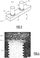
- the end sections 32 of the armor elements 29 are each provided with at least one anchoring element 70, for example two anchoring elements 70 in the case shown.
- Each anchoring element 70 projects transversely from the end section 32 of the armor element 29 towards the outside of the pipe 10.
- the anchoring elements 70 are substantially aligned along the armor element 29, and separated from each other by a distance , measured relative to the center of each anchoring element, between 2 cm and 20 cm, preferably between 2 cm and 10 cm and advantageously between 2 cm and 5 cm.
- the anchoring element 70 is a metal part, for example cylindrical, having an axis X-X '.
- the anchoring element 70 has the shape of a threaded cylinder of axis X-X ', or else of a parallelepiped elongated in a direction X-X' transverse to the armor element 29.
- the axis XX 'of the anchoring element 70 is substantially orthogonal to a local axis YY' of the armor element 29 at the level of the fixing of the anchoring element 70 on the element d. armor 29.
- the anchor element 70 has a length, measured in a direction transverse to the YY 'axis of the armor element 29, and a width, measured in a dimension parallel to the YY' axis of the element. armor 29.
- a ratio between the length and the width of the anchoring element 70 is greater than 2, advantageously greater than 4.
- the anchoring element 70 is for example made of steel, and has a tensile strength limit greater than or equal to 400 MPa, advantageously greater than 600 MPa, as measured according to standards NF EN ISO 6892-1 (Edition November 2016 ), NF EN ISO 898-1 (May 2013 Edition) and NF EN ISO 3506-1 (January 2010 Edition).
- the anchoring element 70 is fixed to the armor element 29 by a weld 72 connecting a lower end 74 of the anchoring element 70 to the armor element 29.
- the length of the anchoring element 70 is greater than a thickness of the armor element 29, measured along the axis XX 'of the anchoring element 70, advantageously two times greater.
- the anchoring element or elements 70 are embedded in the filling material 64.
- a high ratio ensures better retention of the end section 32 of the armor element 29 in the receiving space 52, thanks to a better retention. interaction with filler 64.
- the weld 72 has an extent slightly greater than the width of the anchoring element 70, but less than a width of the armor element 29, measured in a direction orthogonal to the axis XX 'of the element anchor 70 and to the YY 'axis of the armor element 29.
- each anchoring element 70 has a maximum shear strength along the YY' axis of the armor element 29 greater than or equal to 15 kN, advantageously greater than 30 kN, as measured by standards NF EN ISO 6892-1 (Edition November 2016), NF EN ISO 898-1 (Edition May 2013) and NF EN ISO 3506-1 (Edition January 2010).
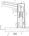
- This method is implemented using a fixing device 80, shown schematically on the figures 5 to 7 , suitable for fixing the anchor element 70.
- the device 80 is for example a welding gun, comprising control electronics able to implement the “fusion-forging” type fixing method.
- the device 80 comprises a tube 81 defining a cavity 82 in which the anchoring element 70 is loaded.
- the cavity 82 has the shape of an elongated cylinder, opening out at one end of the tube 81 through an opening 84.
- the device 80 comprises, in the cavity 82, a guide 85 adapted to guide the anchoring element 70 in the cavity 82, and a clamp 86 holding the anchoring element 70 in the cavity 82.
- the device 80 also comprises a handle 87, located on the opposite side of the tube 81 relative to the opening 84, suitable for handling the device 80, as well as a trigger 88 located close to the handle 87, capable of triggering the process. fixing the anchoring element 70.
- the device 80 comprises at least one neutral gas diffusion nozzle 90 opening into the cavity 82, connected to a pipe 92 for supplying neutral gas. So that the gas can flow in the cavity 82, the guide 85 has perforations 93, and the tube 81 also has radial perforations 94 at the opening 84.
- the device 80 further comprises a striker 95, able to apply a forging force on the anchoring element 70, as well as an electric current generator (not shown), able to generate at least one electric current through the device. anchor element 70 and armor element 29 when they are in contact with each other.
- the electric current generator When the anchoring element 70 is away from the armor element 29, the electric current generator is able to form a fusion electric arc between the anchoring element 70 and the element of armor 29.
- the device 80 is handled by an operator who holds it by the handle 87.
- an anchoring element 70 is provided, placed in the cavity 82 of the device 80.
- the anchoring element 70 is disposed with the lower end 74 oriented towards the opening 84, and is held in the clamp 86 by its free end.
- the anchoring element 70 is for example placed manually in the cavity 82 by the operator.
- the device 80 comprises a loading system capable of positioning the anchoring element 70, and of replacing it at the end of the fixing process. This makes it possible to implement a succession of fastenings of anchoring elements 70, with a time between each fastening less than or equal to 5 seconds.
- the lower end 74 of the anchoring element 70 is flat. But advantageously, the lower end 74 has a protuberance 95A projecting in the direction of the armor element 29. This facilitates the welding of the anchoring element 70 on the armor element 29.
- the tube 81 is brought into contact with an end section 32 of an armor element 29.
- the opening 84 of the cavity 82 extends in the armor element 29 and defines on the armor element 29 an attachment region 96 of the anchoring element 70.
- the anchoring element 70 is initially positioned in contact with the armor element 29.
- the device 80 is oriented so that the axis of the tube 81 is substantially orthogonal to the local axis of the armor element 29.
- the operator activates the trigger 88, and neutral gas is diffused by the nozzles 90.
- the neutral gas flows into the cavity 82, through the perforations 93, until the opening. 84.
- the neutral gas flows in particular around the anchoring element 70 and the fixing region 96, then along the radial perforations 94 to the outside.
- the neutral gas After a diffusion time of the order of 0.5 seconds to 2 seconds, the neutral gas has at least partially expelled the air around the anchor element 70 and the region 96 of attachment.
- the diffusion of neutral gas through the nozzles 90 is maintained during the following steps, and reduces the porosity in the weld 72, which improves its mechanical strength.
- a merger step is triggered after the broadcast time has elapsed.
- the duration of the diffusion step is advantageously programmed in the control electronics of the device 80, and the latter automatically triggers the next step once the time has elapsed. This duration is for example less than 1 second.
- an electric current is generated by the electric current generator through the anchoring element 70 and the armor element 29.
- the anchoring element 70 is then progressively moved away from the armor element 29, which leads to the generation of a fusion electric arc in the gas volume present between the anchoring element 70 and the element. armor 29 by the electric current generator.
- the electric arc of fusion forms in the cavity 82, in the flow of neutral gas.
- the electric fusion arc initially forms between the flat face of the lower end 74 of the anchoring element 70 or when it is present, between the protuberance 95A and the armor element 29, thanks to at the reduced distance between them.
- the weld pool 98 contains molten metal and has a width measured transversely to the axis XX 'greater than the width of the anchoring element 70 measured transversely to the axis X-X'.
- a forging step is then triggered by the control electronics of the device 80, during which the striker 95 exerts a force on the anchoring element 70 along the axis XX 'to forge the lower end 74 against the element d armor 29.
- the lower end 74 is immersed in the weld pool 98, fusing the lower end 74 of the anchoring element 70 and the attachment region 96.
- the method finally comprises a heat treatment step during which the temperature in the cavity 82 drops, which results in solidification of the molten metal and the formation of the weld 72.
- the drop in temperature in the cavity 82 is controlled to ensure good mechanical strength of the weld 72.
- a preheating heat treatment of the anchoring element 70 is carried out before the diffusion step to avoid cold cracking problems at the weld level.
- a post-heating heat treatment of the anchoring element 70 is also carried out after having allowed it to cool for the purpose of solidifying the weld.
- This post-heating heat treatment consists of a step of annealing the anchoring element 70. The anchoring element 70 is thus heated so as to bring it up to temperature in order to homogenize its microstructure and eliminate the residual stresses that may remain. following the implementation of the welding process.
- the method for fixing at least one anchoring element 70 described is particularly advantageous, since it requires a much shorter implementation time than that of the existing methods. In addition, it is carried out with a simpler and partially automated device 80, therefore requiring less technical skills on the part of the operator.
- the method for fixing the anchoring element 70 follows a short-time method not comprising the diffusion of neutral gas.
- the anchoring element 70 has a flange extending transversely to the axis XX 'around the lower end 74, in order to increase the transverse extent of the weld 72. This partly compensates for the lower mechanical strength of the weld 72 due to the formation of a porosity due to the absence of neutral gas around the molten bath 98 during the melting step.
- the melting step comprises a preliminary step of forming an initiation arc prior to the formation of the electric melting arc.
- the ignition arc has an intensity less than an intensity of the fusion electric arc and initiates the fusion of the material of the low end 74 and the attachment region 96, thereby speeding up the process.
- the diffusion of neutral gas is replaced by the placement of a ring of refractory material around the anchoring element 70.
- the ring widens by projecting around the lower end 74. .
- the ring bears on the armor element 29 during the step of placing the device 80, defining a closed space for protecting the molten pool 98 during the melting step.
- the ring contains and isolates the weld pool 98 from the surrounding air, reducing the formation of porosity in the weld 72.
- the ring is partially burned off during the melting step and is easily removed from the anchor 70 after the heat treatment step is completed.
- the method of mounting the end piece 14 according to the invention is carried out as follows.
- each end section 32 of the inner armor layer 24 is unfolded forward.
- At least one anchoring element 70 is fixed on each end section 32, according to the fixing method described above.
- at least two anchoring elements 70 are fixed on each end section 32.
- the end sections 32 are spaced from one another by a distance of the order of a few millimeters.
- At least one anchoring element 70 is fixed on each end section 32 of the elements 29 of the outer armor layer 25 according to the same fixing method as that used for the inner armor layer 24.
- each end section 32 of the outer armor layer 25 is unfolded forward.
- the fixing of at least one anchoring element 70 on the end sections 32 of the armor elements 29 of the armor layers 24, 25 can be carried out before their unfolding forwards.
- the cover 51 is then put in place and fixed to the arch 50, thus forming the reception space 52 around the end sections 32.
- the rear sealing assembly 55 is then put in place and is fixed to the cover 51.
- the end sections 32 of the armor elements 29 of the outer armor layer 25 are folded backwards to allow access to the elements 29 of the inner armor layer 24.
- At least one anchoring element 70 is fixed to each end section 32 of the inner armor layer 24, according to the fixing method described above.
- at least two anchoring elements 70 are fixed on each end section 32.
- At least one anchoring element 70 is fixed on each end section 32 of the elements 29 of the outer armor layer 25 according to the same fixing method as that used for the inner armor layer 24. Then, each end section 32 of the outer armor layer 25 is unfolded forward.
- the fixing of at least one anchoring element 70 on the end sections 32 of the armor elements 29 of the outer armor layer 25 is carried out after their unfolding forwards.
- the end sections 32 of the armor layers 24, 25 are arranged during the manufacture of the end piece 10 for present their conformation as close as possible to their natural conformation, in which they are least constrained.
- At least one anchoring element 70 is attached to each section. end 32 of the armor layers 24, 25 according to the same fixing method as that described above.
- at least two anchoring elements 70 are fixed on each end section 32.
- the cover 51 is then put in place and fixed to the arch 50, thus forming the reception space 52 around the end sections 32.
- the rear sealing assembly 55 is then put in place and is fixed to the cover 51.
- the outer sheath 30 is machined to reveal the outer armor layer 25.
- a rear cannula, an element forming part of the rear sealing assembly 55 is then inserted between the layer. armor 25 and the outer sheath 30.
- a first fixing collar of the "band-it" type is then placed around the outer armor layer 25, near the rear cannula, leaving a sufficient length between the first fixing collar and the rear cannula to allow the fixing of at least one anchoring element 70.
- At least one anchoring element 70 is then fixed on each end section 32 of the elements 29 of the outer armor layer 25, between the first fixing collar and the rear cannula, according to the same fixing method as that described. above.
- at least two anchoring elements 70 are fixed to each end section 32 of the armor elements 29.
- all of the excess lengths of the end sections 32 of each armor element are cut. 29 forming the outer armor layer 25, located in front of the fixing collar.
- Removing the extra lengths of the armor elements 29 of the layer 25 allows access to the inner armor layer 24.
- a second fixing collar is placed around the layer of inner armor 24 leaving a sufficient length between the second fixing collar and the outer armor layer 25, to allow the fixing of at least one anchoring element 70.
- At least one anchoring element is then fixed on each end section 32 of the elements 29 of the inner armor layer 24, between the second fixing collar and the armor layer 25, according to the same fastening method as previously.
- at least two anchoring elements 70 are fixed to each end section 32 of the armor layer 24.
- the cover 51 is then put in place and fixed to the arch 50, thus forming the reception space 52 around the end sections 32.
- the latter method of end fitting mounting has the advantage of shortening the necessary total length of the end fitting as well as reducing the total cost of a flexible pipe having such a fitting. Indeed, the length of the end sections 32 being reduced, it is no longer necessary to provide for the provision of an end cap 50 having a zone having a frustoconical section.
- the filling material 64 is then introduced into the space 52, advantageously in fluid form.
- the material 64 fills the space 52 and solidifies between the arch 50 and the cover 51 around the end sections 32 of the armor elements 29 and around the anchoring elements 70.
- the material 64 solidifies at room temperature, corresponding to the temperature inside the nozzle, and under atmospheric pressure. In cases where the outside temperature is less than 15 ° C., heating means are used to control the solidification of the material 64, for example a heating blanket.
- the solidification time is of the order of a few hours, more particularly from 3 hours to 6 hours.
- the end sections 32 are then embedded in the filling material 64.
- the end piece 14 In operation, when the end piece 14 is connected to another end piece or to a surface assembly, the axial tension transmitted by the armor layers 24, 25 resulting from the weight of the pipe 10 is taken up by the sections 32 embedded in the filling material 82, and more particularly by the anchoring elements 70.
Landscapes
- Engineering & Computer Science (AREA)
- General Engineering & Computer Science (AREA)
- Mechanical Engineering (AREA)
- Wind Motors (AREA)
- Rigid Pipes And Flexible Pipes (AREA)
- Excavating Of Shafts Or Tunnels (AREA)
- Arc Welding In General (AREA)
- Reinforcement Elements For Buildings (AREA)
- Joining Of Building Structures In Genera (AREA)
Claims (15)
- Verfahren zum Befestigen von zumindest einem querverlaufenden Ankerelement (70) an einem Armierungselement (29), welches dazu bestimmt ist, in einem Endanschlussstück (14) einer flexiblen Leitung (10) aufgenommen zu sein, dadurch gekennzeichnet, dass das Verfahren die folgenden Schritte aufweist:- Bereitstellen einer Befestigungsvorrichtung (80), welche eine Kavität (82) hat, welche ein Ankerelement (70) aufnimmt,- Anordnen einer Öffnung (84) der Kavität (82) gegenüber dem Armierungselement (29),- Verschmelzen eines dem Armierungselement (29) gegenüberliegenden Endes (74) des Ankerelements (70) und eines dem Ankerelement (70) gegenüberliegenden Bereichs des Armierungselements (29) in der Kavität (82) der Befestigungsvorrichtung (80),- Schmieden des Ankerelements (70) quer an das Armierungselement (29) mittels der Befestigungsvorrichtung (80) und- Bilden einer Schweißung (72), welche das Ankerelement (70) und das Armierungselement (29) verbindet.
- Verfahren gemäß Anspruch 1, welches einen Schritt des thermischen Behandelns des Ankerelements (70) und des Armierungselements (29) nach dem Schritt des Schmiedens aufweist, wobei sich die Schweißung (72), welche das Ankerelement (70) und das Armierungselement (29) verbindet, während des Schritts des thermischen Behandelns bildet.
- Verfahren gemäß irgendeinem der Ansprüche 1 und 2, wobei die Schweißung (72) eine Quererstreckung hat, welche kleiner als eine Breite des Armierungselements (29) ist.
- Verfahren gemäß irgendeinem der vorherigen Ansprüche, wobei der Schritt des Verschmelzens aufweist das Bilden eines elektrischen Schmelz-Lichtbogens zwischen dem Ankerelement (70) und dem Armierungselement (29).
- Verfahren gemäß irgendeinem der vorherigen Ansprüche, welcher aufweist einen Schritt des Verteilens eines neutralen Gases um zumindest eines des Endes (72) des Ankerelements (70) oder des Bereichs des Armierungselements (29) herum, wobei der Schritt des Verteilens während der Schritte des Verschmelzens und des Schmiedens stattfindet.
- Verfahren gemäß irgendeinem der Ansprüche 4 und 5, wobei der Schritt des Verschmelzens aufweist das Bilden eines Zündbogens vor dem Bilden des elektrischen Schmelz-Lichtbogens, wobei der Zündbogen eine Intensität hat, welche kleiner als eine Intensität des elektrischen Schmelz-Lichtbogens ist.
- Verfahren gemäß irgendeinem der vorherigen Ansprüche, wobei ein wärmefester Ring um das Ende (74) des Ankerelements (70) herum gegenüber dem Armierungselement (29) im Lauf des Schritts des Anordnens angeordnet wird.
- Verfahren gemäß irgendeinem der vorherigen Ansprüche, wobei ein Verhältnis zwischen einer Länge des Ankerelements (70), gemessen entlang einer Richtung, welche quer zum Armierungselement (29) ist, und einer Länge des Ankerelements (70), gemessen entlang einer Richtung, welche parallel zum Armierungselement (29) ist, größer als 2, vorteilhafterweise größer als 4, ist.
- Verfahren gemäß Anspruch 8, wobei die Länge des Ankerelements (70) größer ist als eine Dicke des Armierungselements (29), gemessen entlang derselben Richtung wie die Länge des Ankerelements (70), vorteilhafterweise zweimal größer als die Dicke des Armierungselements (29).
- Verfahren gemäß irgendeinem der vorherigen Ansprüche, wobei das Ankerelement (70) im Wesentlichen zylindrisch ist und eine Achse (X-X') hat, welche im Wesentlichen senkrecht zu einer lokalen Achse (Y-Y') des Armierungselements (29) ist.
- Verfahren gemäß irgendeinem der vorherigen Ansprüche, welches eine Abfolge von Befestigen-Schritten von querverlaufenden Ankerelementen (70) hat, wobei jeder Befestigen-Schritt aufweist die Schritte des Bereitstellens, des Anordnens, des Verschmelzens und des Schmiedens, wobei eine Dauer, welche einen jeweiligen Befestigen-Schritt trennt, kleiner oder gleich 1 Minute, vorteilhafterweise kleiner als 30 Sekunden, ist.
- Verfahren gemäß Anspruch 11, wobei die Ankerelemente (70) getrennt voneinander in einem Abstand entlang des Armierungselements (29), welcher zwischen 2 cm und 20 cm, vorzugsweise zwischen 2 cm und 10 cm und vorteilhafterweise zwischen 2 cm und 5 cm liegt, angeordnet werden.
- Verfahren gemäß irgendeinem der vorherigen Ansprüche, wobei das Ankerelement (70) auf Basis eines Stahls herstellt ist, welcher eine mechanische Zugfestigkeit hat, welche größer oder gleich 400 MPa ist.
- Verfahren zum Montieren eines Endanschlussstücks (14) einer flexiblen Leitung, welches die folgenden Schritte aufweist:- Bereitstellen einer flexiblen Leitung (10), welche aufweist:- zumindest eine rohrförmige Ummantelung (20), welche einen Zirkulationsdurchlass (16) begrenzt, und- zumindest eine Zugarmierungsschicht (24, 25), welche außen bezüglich der rohrförmigen Ummantelung (20) angeordnet ist, wobei die Armierungsschichten (24, 25) eine Mehrzahl von filiformen Armierungselementen (29) aufweisen,- Freilegen eines Endabschnitts (32) jedes Armierungselements (29),- Anordnen einer Endvoute (50) an einem Ende der Leitung (10),- Befestigen von zumindest einem Ankerelement (70) an jedem Armierungselement (29) mittels eines Verfahrens gemäß irgendeinem der Ansprüche 1 bis 13,- Anordnen und Befestigen einer Kappe (51) an der Endvoute (50), welche einen Raum (52) zum Aufnehmen der Endabschnitte (32) der Armierungselemente (29) bildet,- Einbringen eines Füllmaterials (64) in den Raum (52), welches die Ankerelemente (70) einbettet, und- Verfestigen des Füllmaterials (64) um die Endabschnitte (32) und die Ankerelemente (70) herum.
- Flexible Leitung (10), welche aufweist:- zumindest eine rohrförmige Ummantelung (20), welche einen Zirkulationsdurchlass (16) begrenzt,- zumindest eine Zugarmierungsschicht (24, 25), welche außen bezüglich der rohrförmigen Ummantelung (20) angeordnet ist, wobei die Armierungsschichten (24, 25) eine Mehrzahl von filiformen Armierungselementen (29) aufweisen, und- zumindest ein Endanschlussstück (14), welches an einem Ende der Leitung (10) angeordnet ist,wobei das Anschlussstück (14) eine Endvoute (50) und eine Kappe (51) aufweist, welche zwischen einander einen Raum (52) zum Aufnehmen von Endabschnitten (32) der Armierungselemente (29) definieren, wobei der Raum (52) mit einem Füllmaterial (64) gefüllt ist,
wobei jeder Endabschnitt (32) zumindest ein Ankerelement (70) hat, welches auf querverlaufende Weise vorsteht, wobei das Ankerelement (70) in das Füllmaterial (64) eingebettet ist, dadurch gekennzeichnet, dass das Ankerelement (70) am Endabschnitt (32) mittels eines Verfahrens gemäß irgendeinem der Ansprüche 1 bis 13 befestigt wurde.
Applications Claiming Priority (2)
| Application Number | Priority Date | Filing Date | Title |
|---|---|---|---|
| FR1753199A FR3065273B1 (fr) | 2017-04-12 | 2017-04-12 | Procede de fixation d'un element d'ancrage sur un element d'armure d'une conduite flexible, conduite et methode de montage associees |
| PCT/EP2018/059328 WO2018189261A1 (fr) | 2017-04-12 | 2018-04-11 | Procédé de fixation d'un élément d'ancrage sur un élément d'armure d'une conduite flexible, conduite et méthode de montage associées |
Publications (2)
| Publication Number | Publication Date |
|---|---|
| EP3610185A1 EP3610185A1 (de) | 2020-02-19 |
| EP3610185B1 true EP3610185B1 (de) | 2021-02-17 |
Family
ID=59070870
Family Applications (1)
| Application Number | Title | Priority Date | Filing Date |
|---|---|---|---|
| EP18716291.2A Active EP3610185B1 (de) | 2017-04-12 | 2018-04-11 | Verfahren zum befestigen eines verankerungselements an einem element der panzerung eines flexiblen rohrs, zugehöriges rohr und zugehöriges montageverfahren |
Country Status (7)
| Country | Link |
|---|---|
| US (1) | US11187354B2 (de) |
| EP (1) | EP3610185B1 (de) |
| CN (1) | CN110691933A (de) |
| BR (1) | BR112019021187B1 (de) |
| DK (1) | DK3610185T3 (de) |
| FR (1) | FR3065273B1 (de) |
| WO (1) | WO2018189261A1 (de) |
Families Citing this family (1)
| Publication number | Priority date | Publication date | Assignee | Title |
|---|---|---|---|---|
| US11428350B2 (en) | 2020-07-22 | 2022-08-30 | Trinity Bay Equipment Holdings, LLC | Pipe reinforcement strip anchoring systems and methods |
Family Cites Families (18)
| Publication number | Priority date | Publication date | Assignee | Title |
|---|---|---|---|---|
| US4033612A (en) * | 1972-11-21 | 1977-07-05 | Institut Francais Du Petrole, Des Carburants Et Lubrifiants | Armored flexible pipe equipped with a rigid coupling |
| US3934617A (en) * | 1974-08-26 | 1976-01-27 | Controls Southeast, Inc. | Corrugated jacketed pipe assembly having vented enclosures for connecting welds |
| US5362113A (en) * | 1992-09-02 | 1994-11-08 | Tru-Flex Metal Hose Corp. | Spot-welded end fitting for flexible metal piping |
| CA2306495A1 (en) * | 1997-10-14 | 1999-04-22 | Krystyna Izabella Langkjaer | An assembly of an end-fitting and a flexible pipe |
| AU5522700A (en) * | 1999-07-23 | 2001-02-13 | Nkt Flexibles I/S | A method of securing reinforcement wires to an end termination of a pipeline or a cable, an end termination, and uses of the method and the end termination |
| ATE520918T1 (de) * | 2002-11-29 | 2011-09-15 | Nkt Flexibles Is | Mit einem endanschlussstück verbundenes flexibles rohr |
| BRPI0717144B1 (pt) * | 2006-09-29 | 2018-09-25 | Technip France Sa | conjunto de terminação para um umbilical de tubo de aço, e, método para formar um conjunto de terminação para um umbilical de tubo de aço. |
| FR2906595B1 (fr) * | 2006-09-29 | 2010-09-17 | Technip France | Embout de fixation de conduite tubulaire flexible a hautes resistances |
| CN202388107U (zh) * | 2012-03-08 | 2012-08-22 | 阿法拉伐流体设备(昆山)有限公司 | 螺柱焊枪头 |
| DE102012007563B3 (de) * | 2012-04-10 | 2013-05-29 | Salzgitter Mannesmann Line Pipe Gmbh | Vorrichtung zum Verbinden der Enden von Rohren aus Stahl mittels Orbitalschweißen |
| GB201306665D0 (en) | 2013-04-12 | 2013-05-29 | Wellstream Int Ltd | Elongate tape element and method |
| FR3008161B1 (fr) * | 2013-07-03 | 2015-09-04 | Technip France | Embout de connexion d'une conduite flexible avec un organe d'espacement, conduite flexible et procede associes |
| CN103480955A (zh) * | 2013-08-16 | 2014-01-01 | 深圳市元征科技股份有限公司 | 举升机立柱挂轴焊接结构 |
| FR3016020B1 (fr) * | 2013-12-30 | 2016-05-20 | Technip France | Methode de montage d'un embout de fixation d'une conduite tubulaire flexible et installation de mise en œuvre |
| US20150375332A1 (en) | 2014-06-30 | 2015-12-31 | Newfrey Llc | Non-contact laminar flow drawn arc stud welding nozzle and method |
| EP3018383B1 (de) * | 2014-11-10 | 2019-03-06 | Nexans | Abschluss von verstärkungselementen von tiefseekabeln |
| GB201507027D0 (en) * | 2015-04-24 | 2015-06-10 | Ge Oil & Gas Uk Ltd | Flexible pipe components and method of manufacture of flexible pipe |
| FR3046210B1 (fr) * | 2015-12-29 | 2018-02-02 | Technip France | Embout de connexion d'une ligne flexible, ligne flexible et procede de montage associes |
-
2017
- 2017-04-12 FR FR1753199A patent/FR3065273B1/fr not_active Expired - Fee Related
-
2018
- 2018-04-11 CN CN201880033946.4A patent/CN110691933A/zh active Pending
- 2018-04-11 US US16/603,293 patent/US11187354B2/en active Active
- 2018-04-11 DK DK18716291.2T patent/DK3610185T3/da active
- 2018-04-11 EP EP18716291.2A patent/EP3610185B1/de active Active
- 2018-04-11 WO PCT/EP2018/059328 patent/WO2018189261A1/fr unknown
- 2018-04-11 BR BR112019021187-0A patent/BR112019021187B1/pt active IP Right Grant
Non-Patent Citations (1)
| Title |
|---|
| None * |
Also Published As
| Publication number | Publication date |
|---|---|
| BR112019021187A2 (pt) | 2020-04-28 |
| FR3065273B1 (fr) | 2019-06-21 |
| US11187354B2 (en) | 2021-11-30 |
| US20210108743A1 (en) | 2021-04-15 |
| BR112019021187B1 (pt) | 2023-01-24 |
| DK3610185T3 (da) | 2021-05-10 |
| FR3065273A1 (fr) | 2018-10-19 |
| EP3610185A1 (de) | 2020-02-19 |
| CN110691933A (zh) | 2020-01-14 |
| WO2018189261A1 (fr) | 2018-10-18 |
Similar Documents
| Publication | Publication Date | Title |
|---|---|---|
| EP3014157B1 (de) | Schlauch und verfahren dafür | |
| EP3469244B1 (de) | Verbindungsendstück für eine flexible leitung und zugehörige flexible leitung und verfahren | |
| EP2935965B1 (de) | Verbindungsendstück für einen schlauch für den transport von flüssigkeiten und zugehöriges verfahren | |
| EP3286474B1 (de) | Verfahren zur herstellung einer abdichtung in einem endstück einer flexiblen leitung mit einer druckhülle | |
| EP3017229B1 (de) | Flexibles rohr umfassend verbindungsendstück mit einem abstandselement und entsprechendes verfahren zur montage | |
| EP3314155B1 (de) | Verfahren zum einbau eines endstücks eines flexiblen rohrs | |
| WO1999049171A2 (fr) | Assemblage filete de tubes metalliques destines a contenir un fluide corrosif | |
| FR3046449A1 (fr) | Procede d'assemblage d'un premier troncon de conduite flexible avec un deuxieme troncon de conduite flexible, et conduite flexible associee | |
| EP3397886B1 (de) | Verbindungsspitze für eine flexible leitung und zugehörige flexible leitung und montageverfahren | |
| EP3004709B1 (de) | Flexible leitung zur förderung eines fluids, verwendung davon und verfahren | |
| EP3610185B1 (de) | Verfahren zum befestigen eines verankerungselements an einem element der panzerung eines flexiblen rohrs, zugehöriges rohr und zugehöriges montageverfahren | |
| EP2964991B1 (de) | Verfahren zur montage eines endstücks eines flexiblen rohrs und entsprechende vormontage | |
| FR2827032A1 (fr) | Embout pour conduite flexible sans voute de pression et son procede de fabrication | |
| EP3022477A1 (de) | Verbindungsendstück eines schlauchs und entsprechender schlauch | |
| WO2014173874A1 (fr) | Procédé de fabrication d'un embout de connexion d'une conduite flexible et embout associé | |
| WO2020208040A1 (fr) | Procédé de fabrication d'un fil d'armure d'une ligne flexible de transport de fluide et fil d'armure et ligne flexible issus d'un tel procédé | |
| OA17482A (fr) | Méthode de montage d'un embout de conduite flexible et pré-assemblage associé. |
Legal Events
| Date | Code | Title | Description |
|---|---|---|---|
| STAA | Information on the status of an ep patent application or granted ep patent |
Free format text: STATUS: UNKNOWN |
|
| STAA | Information on the status of an ep patent application or granted ep patent |
Free format text: STATUS: THE INTERNATIONAL PUBLICATION HAS BEEN MADE |
|
| PUAI | Public reference made under article 153(3) epc to a published international application that has entered the european phase |
Free format text: ORIGINAL CODE: 0009012 |
|
| STAA | Information on the status of an ep patent application or granted ep patent |
Free format text: STATUS: REQUEST FOR EXAMINATION WAS MADE |
|
| 17P | Request for examination filed |
Effective date: 20191011 |
|
| AK | Designated contracting states |
Kind code of ref document: A1 Designated state(s): AL AT BE BG CH CY CZ DE DK EE ES FI FR GB GR HR HU IE IS IT LI LT LU LV MC MK MT NL NO PL PT RO RS SE SI SK SM TR |
|
| AX | Request for extension of the european patent |
Extension state: BA ME |
|
| DAV | Request for validation of the european patent (deleted) | ||
| DAX | Request for extension of the european patent (deleted) | ||
| GRAP | Despatch of communication of intention to grant a patent |
Free format text: ORIGINAL CODE: EPIDOSNIGR1 |
|
| STAA | Information on the status of an ep patent application or granted ep patent |
Free format text: STATUS: GRANT OF PATENT IS INTENDED |
|
| INTG | Intention to grant announced |
Effective date: 20200916 |
|
| RAP1 | Party data changed (applicant data changed or rights of an application transferred) |
Owner name: TECHNIP N-POWER |
|
| GRAS | Grant fee paid |
Free format text: ORIGINAL CODE: EPIDOSNIGR3 |
|
| GRAA | (expected) grant |
Free format text: ORIGINAL CODE: 0009210 |
|
| STAA | Information on the status of an ep patent application or granted ep patent |
Free format text: STATUS: THE PATENT HAS BEEN GRANTED |
|
| AK | Designated contracting states |
Kind code of ref document: B1 Designated state(s): AL AT BE BG CH CY CZ DE DK EE ES FI FR GB GR HR HU IE IS IT LI LT LU LV MC MK MT NL NO PL PT RO RS SE SI SK SM TR |
|
| REG | Reference to a national code |
Ref country code: GB Ref legal event code: FG4D Free format text: NOT ENGLISH |
|
| REG | Reference to a national code |
Ref country code: CH Ref legal event code: EP |
|
| REG | Reference to a national code |
Ref country code: DE Ref legal event code: R096 Ref document number: 602018012679 Country of ref document: DE |
|
| REG | Reference to a national code |
Ref country code: AT Ref legal event code: REF Ref document number: 1361918 Country of ref document: AT Kind code of ref document: T Effective date: 20210315 |
|
| REG | Reference to a national code |
Ref country code: IE Ref legal event code: FG4D Free format text: LANGUAGE OF EP DOCUMENT: FRENCH |
|
| REG | Reference to a national code |
Ref country code: DK Ref legal event code: T3 Effective date: 20210506 |
|
| REG | Reference to a national code |
Ref country code: NO Ref legal event code: T2 Effective date: 20210217 |
|
| REG | Reference to a national code |
Ref country code: LT Ref legal event code: MG9D |
|
| REG | Reference to a national code |
Ref country code: NL Ref legal event code: MP Effective date: 20210217 |
|
| PG25 | Lapsed in a contracting state [announced via postgrant information from national office to epo] |
Ref country code: LT Free format text: LAPSE BECAUSE OF FAILURE TO SUBMIT A TRANSLATION OF THE DESCRIPTION OR TO PAY THE FEE WITHIN THE PRESCRIBED TIME-LIMIT Effective date: 20210217 Ref country code: PT Free format text: LAPSE BECAUSE OF FAILURE TO SUBMIT A TRANSLATION OF THE DESCRIPTION OR TO PAY THE FEE WITHIN THE PRESCRIBED TIME-LIMIT Effective date: 20210617 Ref country code: FI Free format text: LAPSE BECAUSE OF FAILURE TO SUBMIT A TRANSLATION OF THE DESCRIPTION OR TO PAY THE FEE WITHIN THE PRESCRIBED TIME-LIMIT Effective date: 20210217 Ref country code: GR Free format text: LAPSE BECAUSE OF FAILURE TO SUBMIT A TRANSLATION OF THE DESCRIPTION OR TO PAY THE FEE WITHIN THE PRESCRIBED TIME-LIMIT Effective date: 20210518 Ref country code: HR Free format text: LAPSE BECAUSE OF FAILURE TO SUBMIT A TRANSLATION OF THE DESCRIPTION OR TO PAY THE FEE WITHIN THE PRESCRIBED TIME-LIMIT Effective date: 20210217 Ref country code: BG Free format text: LAPSE BECAUSE OF FAILURE TO SUBMIT A TRANSLATION OF THE DESCRIPTION OR TO PAY THE FEE WITHIN THE PRESCRIBED TIME-LIMIT Effective date: 20210517 |
|
| REG | Reference to a national code |
Ref country code: AT Ref legal event code: MK05 Ref document number: 1361918 Country of ref document: AT Kind code of ref document: T Effective date: 20210217 |
|
| PG25 | Lapsed in a contracting state [announced via postgrant information from national office to epo] |
Ref country code: LV Free format text: LAPSE BECAUSE OF FAILURE TO SUBMIT A TRANSLATION OF THE DESCRIPTION OR TO PAY THE FEE WITHIN THE PRESCRIBED TIME-LIMIT Effective date: 20210217 Ref country code: NL Free format text: LAPSE BECAUSE OF FAILURE TO SUBMIT A TRANSLATION OF THE DESCRIPTION OR TO PAY THE FEE WITHIN THE PRESCRIBED TIME-LIMIT Effective date: 20210217 Ref country code: PL Free format text: LAPSE BECAUSE OF FAILURE TO SUBMIT A TRANSLATION OF THE DESCRIPTION OR TO PAY THE FEE WITHIN THE PRESCRIBED TIME-LIMIT Effective date: 20210217 Ref country code: RS Free format text: LAPSE BECAUSE OF FAILURE TO SUBMIT A TRANSLATION OF THE DESCRIPTION OR TO PAY THE FEE WITHIN THE PRESCRIBED TIME-LIMIT Effective date: 20210217 Ref country code: SE Free format text: LAPSE BECAUSE OF FAILURE TO SUBMIT A TRANSLATION OF THE DESCRIPTION OR TO PAY THE FEE WITHIN THE PRESCRIBED TIME-LIMIT Effective date: 20210217 |
|
| PG25 | Lapsed in a contracting state [announced via postgrant information from national office to epo] |
Ref country code: IS Free format text: LAPSE BECAUSE OF FAILURE TO SUBMIT A TRANSLATION OF THE DESCRIPTION OR TO PAY THE FEE WITHIN THE PRESCRIBED TIME-LIMIT Effective date: 20210617 |
|
| PG25 | Lapsed in a contracting state [announced via postgrant information from national office to epo] |
Ref country code: EE Free format text: LAPSE BECAUSE OF FAILURE TO SUBMIT A TRANSLATION OF THE DESCRIPTION OR TO PAY THE FEE WITHIN THE PRESCRIBED TIME-LIMIT Effective date: 20210217 Ref country code: CZ Free format text: LAPSE BECAUSE OF FAILURE TO SUBMIT A TRANSLATION OF THE DESCRIPTION OR TO PAY THE FEE WITHIN THE PRESCRIBED TIME-LIMIT Effective date: 20210217 Ref country code: SM Free format text: LAPSE BECAUSE OF FAILURE TO SUBMIT A TRANSLATION OF THE DESCRIPTION OR TO PAY THE FEE WITHIN THE PRESCRIBED TIME-LIMIT Effective date: 20210217 Ref country code: AT Free format text: LAPSE BECAUSE OF FAILURE TO SUBMIT A TRANSLATION OF THE DESCRIPTION OR TO PAY THE FEE WITHIN THE PRESCRIBED TIME-LIMIT Effective date: 20210217 |
|
| REG | Reference to a national code |
Ref country code: DE Ref legal event code: R119 Ref document number: 602018012679 Country of ref document: DE |
|
| PG25 | Lapsed in a contracting state [announced via postgrant information from national office to epo] |
Ref country code: MC Free format text: LAPSE BECAUSE OF FAILURE TO SUBMIT A TRANSLATION OF THE DESCRIPTION OR TO PAY THE FEE WITHIN THE PRESCRIBED TIME-LIMIT Effective date: 20210217 Ref country code: SK Free format text: LAPSE BECAUSE OF FAILURE TO SUBMIT A TRANSLATION OF THE DESCRIPTION OR TO PAY THE FEE WITHIN THE PRESCRIBED TIME-LIMIT Effective date: 20210217 Ref country code: RO Free format text: LAPSE BECAUSE OF FAILURE TO SUBMIT A TRANSLATION OF THE DESCRIPTION OR TO PAY THE FEE WITHIN THE PRESCRIBED TIME-LIMIT Effective date: 20210217 |
|
| PLBE | No opposition filed within time limit |
Free format text: ORIGINAL CODE: 0009261 |
|
| STAA | Information on the status of an ep patent application or granted ep patent |
Free format text: STATUS: NO OPPOSITION FILED WITHIN TIME LIMIT |
|
| PG25 | Lapsed in a contracting state [announced via postgrant information from national office to epo] |
Ref country code: LU Free format text: LAPSE BECAUSE OF NON-PAYMENT OF DUE FEES Effective date: 20210411 |
|
| REG | Reference to a national code |
Ref country code: BE Ref legal event code: MM Effective date: 20210430 |
|
| 26N | No opposition filed |
Effective date: 20211118 |
|
| PG25 | Lapsed in a contracting state [announced via postgrant information from national office to epo] |
Ref country code: ES Free format text: LAPSE BECAUSE OF FAILURE TO SUBMIT A TRANSLATION OF THE DESCRIPTION OR TO PAY THE FEE WITHIN THE PRESCRIBED TIME-LIMIT Effective date: 20210217 Ref country code: LI Free format text: LAPSE BECAUSE OF NON-PAYMENT OF DUE FEES Effective date: 20210430 Ref country code: AL Free format text: LAPSE BECAUSE OF FAILURE TO SUBMIT A TRANSLATION OF THE DESCRIPTION OR TO PAY THE FEE WITHIN THE PRESCRIBED TIME-LIMIT Effective date: 20210217 Ref country code: DE Free format text: LAPSE BECAUSE OF NON-PAYMENT OF DUE FEES Effective date: 20211103 Ref country code: CH Free format text: LAPSE BECAUSE OF NON-PAYMENT OF DUE FEES Effective date: 20210430 |
|
| PG25 | Lapsed in a contracting state [announced via postgrant information from national office to epo] |
Ref country code: SI Free format text: LAPSE BECAUSE OF FAILURE TO SUBMIT A TRANSLATION OF THE DESCRIPTION OR TO PAY THE FEE WITHIN THE PRESCRIBED TIME-LIMIT Effective date: 20210217 |
|
| PG25 | Lapsed in a contracting state [announced via postgrant information from national office to epo] |
Ref country code: IT Free format text: LAPSE BECAUSE OF FAILURE TO SUBMIT A TRANSLATION OF THE DESCRIPTION OR TO PAY THE FEE WITHIN THE PRESCRIBED TIME-LIMIT Effective date: 20210217 Ref country code: IE Free format text: LAPSE BECAUSE OF NON-PAYMENT OF DUE FEES Effective date: 20210411 |
|
| PG25 | Lapsed in a contracting state [announced via postgrant information from national office to epo] |
Ref country code: IS Free format text: LAPSE BECAUSE OF FAILURE TO SUBMIT A TRANSLATION OF THE DESCRIPTION OR TO PAY THE FEE WITHIN THE PRESCRIBED TIME-LIMIT Effective date: 20210617 |
|
| PG25 | Lapsed in a contracting state [announced via postgrant information from national office to epo] |
Ref country code: BE Free format text: LAPSE BECAUSE OF NON-PAYMENT OF DUE FEES Effective date: 20210430 |
|
| PGFP | Annual fee paid to national office [announced via postgrant information from national office to epo] |
Ref country code: NO Payment date: 20230324 Year of fee payment: 6 Ref country code: DK Payment date: 20230327 Year of fee payment: 6 |
|
| P01 | Opt-out of the competence of the unified patent court (upc) registered |
Effective date: 20230516 |
|
| PG25 | Lapsed in a contracting state [announced via postgrant information from national office to epo] |
Ref country code: CY Free format text: LAPSE BECAUSE OF FAILURE TO SUBMIT A TRANSLATION OF THE DESCRIPTION OR TO PAY THE FEE WITHIN THE PRESCRIBED TIME-LIMIT Effective date: 20210217 |
|
| PG25 | Lapsed in a contracting state [announced via postgrant information from national office to epo] |
Ref country code: HU Free format text: LAPSE BECAUSE OF FAILURE TO SUBMIT A TRANSLATION OF THE DESCRIPTION OR TO PAY THE FEE WITHIN THE PRESCRIBED TIME-LIMIT; INVALID AB INITIO Effective date: 20180411 |
|
| PGFP | Annual fee paid to national office [announced via postgrant information from national office to epo] |
Ref country code: FR Payment date: 20230420 Year of fee payment: 6 |
|
| PGFP | Annual fee paid to national office [announced via postgrant information from national office to epo] |
Ref country code: GB Payment date: 20230424 Year of fee payment: 6 |
|
| PG25 | Lapsed in a contracting state [announced via postgrant information from national office to epo] |
Ref country code: MK Free format text: LAPSE BECAUSE OF FAILURE TO SUBMIT A TRANSLATION OF THE DESCRIPTION OR TO PAY THE FEE WITHIN THE PRESCRIBED TIME-LIMIT Effective date: 20210217 |