EP3609788B1 - Systems for capturing a client vehicle and related methods - Google Patents
Systems for capturing a client vehicle and related methods Download PDFInfo
- Publication number
- EP3609788B1 EP3609788B1 EP18707515.5A EP18707515A EP3609788B1 EP 3609788 B1 EP3609788 B1 EP 3609788B1 EP 18707515 A EP18707515 A EP 18707515A EP 3609788 B1 EP3609788 B1 EP 3609788B1
- Authority
- EP
- European Patent Office
- Prior art keywords
- client vehicle
- probe
- assembly
- client
- fingers
- Prior art date
- Legal status (The legal status is an assumption and is not a legal conclusion. Google has not performed a legal analysis and makes no representation as to the accuracy of the status listed.)
- Active
Links
Images


Classifications
-
- B—PERFORMING OPERATIONS; TRANSPORTING
- B64—AIRCRAFT; AVIATION; COSMONAUTICS
- B64D—EQUIPMENT FOR FITTING IN OR TO AIRCRAFT; FLIGHT SUITS; PARACHUTES; ARRANGEMENT OR MOUNTING OF POWER PLANTS OR PROPULSION TRANSMISSIONS IN AIRCRAFT
- B64D39/00—Refuelling during flight
- B64D39/06—Connecting hose to aircraft; Disconnecting hose therefrom
-
- B—PERFORMING OPERATIONS; TRANSPORTING
- B64—AIRCRAFT; AVIATION; COSMONAUTICS
- B64G—COSMONAUTICS; VEHICLES OR EQUIPMENT THEREFOR
- B64G1/00—Cosmonautic vehicles
- B64G1/10—Artificial satellites; Systems of such satellites; Interplanetary vehicles
- B64G1/1078—Maintenance satellites
-
- B—PERFORMING OPERATIONS; TRANSPORTING
- B64—AIRCRAFT; AVIATION; COSMONAUTICS
- B64G—COSMONAUTICS; VEHICLES OR EQUIPMENT THEREFOR
- B64G1/00—Cosmonautic vehicles
- B64G1/22—Parts of, or equipment specially adapted for fitting in or to, cosmonautic vehicles
- B64G1/64—Systems for coupling or separating cosmonautic vehicles or parts thereof, e.g. docking arrangements
- B64G1/646—Docking or rendezvous systems
- B64G1/6462—Docking or rendezvous systems characterised by the means for engaging other vehicles
- B64G1/6464—Docking probes and receivers
-
- F—MECHANICAL ENGINEERING; LIGHTING; HEATING; WEAPONS; BLASTING
- F42—AMMUNITION; BLASTING
- F42B—EXPLOSIVE CHARGES, e.g. FOR BLASTING, FIREWORKS, AMMUNITION
- F42B15/00—Self-propelled projectiles or missiles, e.g. rockets; Guided missiles
- F42B15/36—Means for interconnecting rocket-motor and body section; Multi-stage connectors; Disconnecting means
Definitions
- the present disclosure relates to systems, devices, assemblies, apparatus, and methods for spacecraft docking, and more specifically, to a capture assembly including an apparatus for insertion and capture of an engine of a spacecraft and related methods.
- spacecraft orbit the Earth for performing various functions including, for example, telecommunication, GPS navigation, weather forecasting, and mapping. Like all machines, spacecraft periodically require servicing to extend their functioning life span. Servicing may include, for example, component repair, refueling, orbit raising, station-keeping, momentum balancing, or other maintenance. To accomplish this, a servicing spacecraft may be sent into orbit to dock with a client spacecraft requiring maintenance, and subsequent to docking, perform life-extending maintenance on the client. Spacecraft docking generally involves "cooperative" targets, where a first spacecraft attaches to a second spacecraft that is designed to be docked with. However, various spacecraft do not have dedicated docking features. Such spacecraft will often have liquid apogee engines and a launch vehicle separation ring. These spacecraft still benefit from servicing, but provide added difficulty due to the lack of dedicated docking features. Without life extension maintenance, these spacecraft may fall out of service, and replacement is generally extraordinarily expensive and can have a lead time of years.
- JPH01226497 discloses a system that provides an active side module comprising a freely projectable probe for catching and docking with a passive side module that is provided with a drogue for engaging with the probe.
- an active side module comprising a freely projectable probe for catching and docking with a passive side module that is provided with a drogue for engaging with the probe.
- mechanical complexity increases the likelihood of component failure, which can result in failure in the docking and maintenance process.
- EP0092602 discloses another kind of capture mechanism. Accordingly, an improved capture assembly for docking to a spacecraft is desirable.
- a system for capturing an client vehicle is provided in claim 1 and a method of capturing a client vehicle is provided in claim 18.
- a servicer spacecraft also known as a mission extension vehicle (“MEV")
- MEV mission extension vehicle
- the MEV includes a capture assembly comprising a client spacecraft grasping portion and a compliant extension assembly.
- the grasping portion comprises an apparatus such as a probe for insertion into a nozzle of the liquid apogee engine.
- the compliant extension assembly may provide for the extension and retraction of the probe.
- the probe has a deployable assembly at a forward portion for engagement with an interior surface of a combustion chamber of the liquid apogee engine.
- Some embodiments of the disclosure allow a spacecraft (e.g., a servicer) to dock to another spacecraft (e.g., a client) in cases where the client may not be designed to be docked with, but has design features suitable for connection to the capture assembly including, for example, a launch vehicle separation ring (or 4-point mount), and a liquid apogee engine.
- a spacecraft e.g., a servicer
- a client e.g., a client
- design features suitable for connection to the capture assembly including, for example, a launch vehicle separation ring (or 4-point mount), and a liquid apogee engine.
- embodiments of the disclosure may be used to dock to geostationary communication satellites, or various other spacecraft that do not have specifically designated docking hardware and/or docking assist features.
- Some embodiments provide benefits in the form of a relatively simple docking architecture with compliancy for improved reliability and safety, that is, preventing damage to the spacecraft.
- the term "substantially" in reference to a given parameter means and includes to a degree that one skilled in the art would understand that the given parameter, property, or condition is met with a small degree of variance, such as within acceptable manufacturing tolerances.
- a parameter that is substantially met may be at least about 90% met, at least about 95% met, or even at least about 99% met.
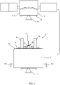
- FIG. 1 depicts a side elevational view of the present disclosure in which a servicer spacecraft 10 may be operated to approach, capture, dock to, or service a client vehicle 11, according to one or more embodiments of the disclosure.
- Servicer spacecraft 10 and client vehicle 11 each may be a satellite or other spacecraft situated in orbit around a body.
- the servicer spacecraft 10 may be a spacecraft designed to approach, capture, dock to and undock from, and service a client vehicle 11.
- Servicer spacecraft 10 may facilitate providing services to client vehicle 11 including station-keeping, orbital raising, momentum balancing, attitude control, relocation, de-orbit, refueling, repair, or other services that may be provided on-orbit.
- Servicer spacecraft 10 may be designed to provide service to more than one client vehicle 11, and therefore may be provided with a docking mechanism that allows the servicer spacecraft 10 to dock and undock from multiple client vehicles 11, including where one or more of the client vehicles 11 comprises an engine 18 of a different size or shape from one or more of the other client vehicles 11.
- the servicer spacecraft 10 generally comprises a spacecraft body 12, a docking platform 14, stanchions 16, a main thruster 17, gimbaled thrusters 18.2 and a capture assembly 20.
- Client vehicle 11 is a spacecraft that can be captured by the servicer spacecraft 10.
- Client vehicle 11 may be in low earth orbit, medium earth orbit, geosynchronous orbit, beyond geosynchronous orbit, or in another orbit around a body such as Earth.
- Client vehicle 11 has a body 11.2, an engine 18, and a separation ring 19.
- Engine 18 can be any type of suitable engine for a spacecraft.
- engine 18 is a liquid apogee engine, solid fuel motor, RCS thruster, or other type of engine or motor.
- Engine 18 may be positioned on the zenith deck of the client vehicle 11, which, in the case of a spacecraft orbiting the Earth, is a deck of the spacecraft substantially positioned opposite the Earth.
- Capture assembly 20 of servicer spacecraft 10 may be configured to capture client vehicle 11 at engine 18 and to pull client vehicle 11 and servicer spacecraft 10 together for docking.
- stanchions 16 may abut separation ring 19 of client vehicle 11 and capture assembly 20 may retain the respective spacecraft together.
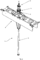
- FIG. 2 depicts an isometric view of capture assembly 20 of servicer spacecraft 10 according to certain embodiments.
- capture assembly 20 includes a bus support structure 21 that provides support for components of the capture assembly 20.
- Capture assembly 20 includes a probe assembly 22 (see also FIG. 1 ).
- Probe assembly 22 may include functionality that allows for extension or retraction of a portion of probe assembly 22 to facilitate docking of servicer spacecraft 10 with client vehicle 11. When servicer spacecraft 10 is docked to client vehicle 11, a portion of probe assembly 22 may be inserted into engine 18.
- Capture assembly 20 may also include a compliant extension assembly 23 (see FIG. 1 ), which may include a lance comprising a compliant boom 43 and a sheath 24 for housing the compliant boom 43 in some embodiments.
- Boom 43 of compliant extension assembly 23 may be extended in a direction substantially away from or retracted in a direction substantially toward a nadir deck 13 (see FIG. 1 ) of servicer spacecraft 10 during operation. Docking of servicer spacecraft 10 to client vehicle 11 may include extending boom 43 from sheath 24 substantially in a direction toward engine 18 of client vehicle 11. In some embodiments, boom 43 of compliant extension assembly 23 may be extended up to two meters or more from sheath 24. Capture assembly 20 may further include harness 25 for providing electrical connection between probe assembly 22 and servicer spacecraft 10. Harness 25 may be provided as a spiral harness to facilitate the extension or retraction of boom 43.
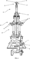
- FIG. 3 shows a perspective, partial cross-sectional view of probe assembly 22 according to one embodiment.
- a probe tip 26 is positioned at a distal end of probe assembly 22.
- Probe tip 26 may have one or more rollers, wheels, or other friction reducing apparatuses 28 positioned at its distal end. In various embodiments, there may be one, two, three, four, five or more rollers, wheels, or other friction reducing apparatuses 28 positioned at the distal end of probe tip 26. Friction reducing apparatuses 28 may be dry film lubricated and may have a spindle ratio of greater than or equal to 3.
- Probe tip 26 may be movably attached to probe assembly 22.
- probe assembly 22 may include boom compression spring 31. Boom compression spring 31 may assist in preventing boom 43 from being damaged upon contact of probe tip 26 with any part of client vehicle 11.
- Probe tip 26 includes one or more fingers 27.
- probe tip 26 may include one, two, three, four, or more fingers.
- Fingers 27 may be biased into an open position by a spring or other device. Fingers 27 may be compliant such that a biasing force imparted on fingers 27 may cause fingers to pivot in a direction toward probe tip 26 upon docking or undocking of servicer spacecraft 10 to client vehicle 11.
- a wheel, roller, or other friction reducing apparatus may be positioned at the end of one or more fingers 27 to reduce any frictional force imparted by fingers 27 upon docking or undocking of servicer spacecraft 10 to client vehicle 11.
- the wheel, roller, or other friction reducing apparatus positioned at the end of one or more fingers 27 may be dry film lubricated and may have a spindle ratio of greater than or equal to 3.
- Probe assembly 22 includes a quillon assembly 29.
- Quillon assembly 29 may comprise one or more rollers 30.
- quillon assembly 29 may include one, two, three, four, or more rollers 30.
- Rollers 30 may be dry film lubricated and may have a spindle ratio of greater than or equal to 3.
- Quillon assembly 29 is movable relative to probe assembly 22 to facilitate docking of servicer spacecraft 10 to client vehicle 11.
- quillon assembly 29 may include a translational joint slide allowing quillon assembly 29 to translate in an axial manner toward or away from probe tip 26.
- Probe assembly 22 Upon docking of servicer spacecraft 10 to client vehicle 11, rollers 30 may contact a side wall of engine 18 of client vehicle 11 in a manner that may limit rotation of servicer spacecraft 10 in relation to client vehicle 11 during docking (e.g., to cinch or otherwise secure the client vehicle 11).
- Probe assembly 22 also includes an actuator 32. Actuator 32 may be configured to provide motion to actuate linear motion of components of probe assembly 22. Actuator 32 causes an internal portion of probe tip 26 to move toward or away from client vehicle 11 that may assist in the docking or undocking of servicer spacecraft 10 to client vehicle 11. Actuator 32 causes fingers 27 to retract in a direction toward probe tip 26 to facilitate the docking or undocking of servicer spacecraft 10 to client vehicle 11.
- probe assembly 22 may include boom tension indicator spring 33 or other components that facilitate providing a preload tension between servicer spacecraft 10 and client vehicle 11 or determining the amount of preload tension present when servicer spacecraft 10 and client vehicle 11 are docked.
- boom 43 of compliant extension assembly 23 may be partially extended from sheath 24.
- quillons 29 are retracted before docking is initiated.
- boom 43 is extended into nozzle of engine 18.
- the rate of extension of boom 43 may be implemented to reduce the amount of time friction can be present during the capture event, which in some embodiments may be greater than or equal to 15 millimeters per second.
- fingers 27 may retract toward probe tip 26.
- springs or another apparatus 38 may bias fingers 27 (see FIG. 9 ) outward from probe tip 26 into a deployed position (e.g., in order to contact, secure, cinch, the client vehicle).
- the fingers 27 may be extended and/or secured passively (e.g., without the use of a motorized actuator) in the deployed position.
- the insertion of probe tip 26 into engine 18 may create less than or equal to 5 millimeters/second delta velocity between servicer spacecraft 10 and client vehicle 11.
- Boom 43 may then be retracted toward servicer spacecraft 10 until stanchions 16 contact separation ring 19.
- quillons 29 may be extended to allow for contact between quillons 29 and sides of engine 18 (e.g., in order to contact, secure, cinch, the client vehicle).
- the boom 43 continues to retract toward servicer spacecraft 10 until a tension exists between servicer spacecraft 10 and client vehicle 11 sufficient to trigger the boom tension indicator spring 33 or other switch or indicator.
- Boom 43 of compliant extension assembly 23 may be extended in a direction away from servicer spacecraft 10 toward client vehicle 11 until the tension between servicer spacecraft 10 and client vehicle 11 releases, as indicated by boom tension indicator spring 33 or other switch or indicator.
- quillons 29 may be retracted before undocking.
- Boom 43 is extended an amount sufficient to allow clearance for fingers 29 to retract in a direction toward probe tip 26 and is then retracted in a direction toward servicer spacecraft 10.
- Servicer spacecraft 10 may then maneuver away from client vehicle 11.
- FIG. 4 shows a perspective, partial cross-sectional view of a probe assembly 22 according to another embodiment.
- a probe tip 26 is positioned at a distal end of probe assembly 22.
- Probe tip 26 includes one or more fingers 27.
- Probe tip 26 may include one, two, three, four, or more fingers.
- Fingers 27 may be biased into a closed position by a spring or other device.
- a wheel, roller, or other friction reducing apparatus 28 may be positioned at the end of one or more fingers 27 to reduce any frictional force imparted by fingers 27 upon docking or undocking of servicer spacecraft 10 to client vehicle 11.
- Rollers 28 may be provided by means of one or more tip rollers provided on a floating pin.
- Wheel, roller, or other friction reducing apparatus 28 positioned at the end of one or more fingers 27 may be dry film lubricated and may have a spindle ratio of greater than or equal to 3.
- Probe tip 26 may be movably attached to probe assembly 22.
- probe assembly 22 may include boom compression spring 31. Boom compression spring 31 may assist in preventing boom 43 from being damaged upon contact of probe tip 26 with any part of client vehicle 11.
- probe assembly 22 may also include one or more throat detectors 35. Throat detectors 35 may be provided with rollers, wheels, or other friction reducing apparatuses on their tips. Wheels, rollers, or other friction reducing apparatuses of throat detector 35 may be dry film lubricated and may have a spindle ratio of greater than or equal to 3. Throat detectors 35 facilitate the probe assembly 22 by sensing the relative position of probe tip 26 within engine 18 of client vehicle 11.
- Probe assembly 22 includes a quillon assembly 29.
- Quillon assembly 29 may comprise one or more rollers 30.
- Quillon assembly 29 may include one, two, three, four, five, six, seven, eight, or more rollers 30.
- Rollers 30 may be dry film lubricated and may have a spindle ratio of greater than or equal to 3.
- Quillon assembly 29 is movable relative to probe tip 26 to facilitate docking and preloading of servicer spacecraft 10 to client vehicle 11. Upon docking of servicer spacecraft 10 to client vehicle 11, rollers 30 may contact a side wall of engine 18 of client vehicle 11 in a manner that may limit rotation of servicer spacecraft 10 in relation to client vehicle 11 during docking.
- Probe assembly also includes an actuator 32.
- Actuator 32 may be configured to provide motion to actuate linear motion of components of probe assembly 22. Actuator 32 causes internal components of probe tip 26 to move toward or away from client vehicle 11 that may assist in the docking or undocking of servicer spacecraft 10 to client vehicle 11. Actuator 32 causes quillon assembly 29 to cinch the apex of throat 39 of engine 18. Actuator 32 may cause cam bar 34 to translate relative to probe tip 26 to actuate fingers 27 to a deployed position or to a stowed position to facilitate the docking or undocking of servicer spacecraft 10 to client vehicle 11.
- probe assembly 22 may include boom tension indicator spring 33 or other components that facilitate providing a preload tension between servicer spacecraft 10 and client vehicle 11 or determining the amount of preload tension present when servicer spacecraft 10 and client vehicle 11 are docked.
- the preload tension between servicer spacecraft 10 and client vehicle 11 is greater than or equal to 15 lbf (66.723324 N).
- Boom compression spring 31 may limit peak levels of impact load.
- FIGS. 5-9 depict top and side elevation and cross-sectional views of probe tip 26 according to one embodiment.
- FIG. 5 is a top elevation view of probe tip 26 depicting two fingers 27 and four rollers 28 according to one embodiment.
- FIG. 6 is a side elevation view of probe tip 26 depicting two fingers 27 and rollers 28 according to one embodiment.
- FIG. 6 further depicts finger pivot pins 37 that provide for pivotal motion of fingers 27.
- FIG. 7 is a side cross-sectional view of probe tip 26 depicting fingers 27 in a retracted position.
- Fingers 27 may be provided with one or more splay rollers 36. Splay rollers 36 facilitate the deployment of fingers 27 in a pivotal motion when cam bar 34 is extended toward the distal end of probe tip 26.
- FIG. 5 is a top elevation view of probe tip 26 depicting two fingers 27 and four rollers 28 according to one embodiment.
- FIG. 6 is a side elevation view of probe tip 26 depicting two fingers 27 and rollers 28 according to one embodiment.
- FIG. 6 further
- FIG. 8 is a side cross-sectional view of probe tip 26 depicting fingers 27 in a deployed position. Fingers 27 may be provided with one or more splay rollers 36. As shown in FIG. 8 , cam bar 34 may be extended toward the distal end of probe tip 26, providing a force on splay rollers 36 to deploy fingers 27 in a pivotal motion.
- FIG. 9 is a side cross-section view of probe tip 26 depicting fingers 27 in a deployed position. Springs or other apparatus 38 may be used to bias fingers 27 in a non-deployed position. In some embodiments, there may be one, two, or more springs 38 per finger 27.
- FIGS. 10 and 11 depict a cross-sectional view of engine 18 upon insertion of probe tip 26.
- probe tip 26 has been inserted through the throat 39 of engine 18 until throat detectors 35 sense that the probe assembly 22 is positioned for docking.
- cam bar 34 has been extended to cause fingers 27 to deploy and contact throat 39.
- Quillon assembly 29 has been deployed to facilitate applying a cinch load on the apex of throat 39 of engine 18.
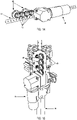
- FIG. 12 shows a perspective, partial cross-sectional side view of a probe assembly 22 according to another embodiment.
- a probe tip 26 is positioned at a distal end of probe assembly 22.
- Probe tip 26 includes one or more fingers 27.
- Probe tip 26 may include one, two, three, four, or more fingers.
- Fingers 27 may be biased into an open or closed position by a spring or other device. Fingers 27 may be compliant such that a biasing force imparted on fingers 27 may allow fingers to pivot in a direction toward or away from probe tip 26 upon docking or undocking of servicer spacecraft 10 to client vehicle 11.
- a wheel, roller, or other friction reducing apparatus 28 may be positioned at the end of one or more fingers 27 to reduce any frictional force imparted by fingers 27 upon docking or undocking of servicer spacecraft 10 to client vehicle 11.
- Wheel, roller, or other friction reducing apparatus 28 positioned at the end of one or more fingers 27 may be dry film lubricated and may have a spindle ratio of greater than or equal to 3.
- Probe tip 26 may have one or more rollers, wheels, or other friction reducing apparatuses 28 positioned at its distal end. There may be one, two, three, four, five or more rollers, wheels, or other friction reducing apparatuses 28 positioned at the distal end of probe tip 26.
- Wheel, roller, or other friction reducing apparatus 28 may be dry film lubricated and may have a spindle ratio of greater than or equal to 3.
- Probe tip 26 may be movably attached to probe assembly 22.
- Some embodiments may include boom compression spring 31 in probe assembly 22. Boom compression spring 31 may assist in preventing boom 43 from being damaged upon contact of probe tip 26 with any part of client vehicle 11.
- Probe assembly 22 includes a quillon assembly 29.
- Quillon assembly 29 may comprise one or more rollers 30.
- Quillon assembly 29 may include one, two, three, four, or more rollers 30.
- Rollers 30 may be dry film lubricated and may have a spindle ratio of greater than or equal to 3.
- Quillon assembly 29 is movable to cinch the apex of throat 39 of engine 18.
- Probe assembly 22 also includes an actuator 32. Actuator 32 may be configured to provide motion to actuate linear motion of components of probe assembly 22. Actuator 32 causes internal components of probe tip 26 to move toward or away from client vehicle 11 that may assist in the docking or undocking of servicer spacecraft 10 to client vehicle 11. Actuator 32 causes quillon assembly 29 to cinch the apex of throat 39 of engine 18.
- probe assembly 22 may include boom tension indicator spring 33 or other components that facilitate providing a preload tension between servicer spacecraft 10 and client vehicle 11 or determining the amount of preload tension present when servicer spacecraft 10 and client vehicle 11 when docked.
- boom tension indicator spring 33 or other components that facilitate providing a preload tension between servicer spacecraft 10 and client vehicle 11 or determining the amount of preload tension present when servicer spacecraft 10 and client vehicle 11 when docked.
- FIGS. 13-15 depict a compliant extension assembly 23 in the form of a lance system 40 according to one embodiment.
- Lance system 40 may be used in combination with a capture assembly 20 to facilitate the docking of a servicer spacecraft 10 to a client vehicle 11.
- Lance system 40 may comprise a lance motor 41, a drive system 42, a sheath 24, and a boom 43.
- Tip plug 47 is provided at a distal end of boom 43, and provides a mechanical interface between boom 43 and probe assembly 22 (see FIGS. 1 and 2 ).
- Lance motor 41 may be engaged to operatively control the extension of boom 43 from or retraction of boom 43 into sheath 24 using drive system 42.
- Drive system 42 provides a mechanical interface between lance motor 41 and boom 43, and may be provided in the form of a tractor drive system 44, that may include one or more gears 45 that may drive one or more pinned guide pulleys 46.
- Boom 43 may be provided with pin holes 48 corresponding to the pins on pinned guide pulleys 46.
- the embodiment depicted in FIGS. 13-15 may be operated by causing lance motor 41 to drive gears 45 of drive system 42.
- Gears 45 thereby drive rotation of pinned guide pulleys 46, the rotation of which causes the extension or retraction of boom 43 by means of interaction between pinned guide pulleys 46 and the pin holes 48 of boom 43.
- Sheath 24 houses the portion of boom 43 not extended from the nadir deck 13 of servicer spacecraft 10.
- boom 43 may be designed to be substantially rigid to facilitate docking of servicer spacecraft 10 to client vehicle 11.
- boom 43 may be designed to be substantially flexible to facilitate docking of servicer spacecraft 10 to client vehicle 11 by reducing friction between probe assembly 22 and engine 18 by reducing normal forces exerted on client vehicle 11 by probe assembly 22. Such normal forces may be present due to misalignment of probe assembly 22 during docking. Flexibility of boom 43 may reduce normal forces between servicer spacecraft 10 and client vehicle 11 during docking to less than or equal to 0.25 lbf (1.112055 N).
- servicer spacecraft 10 may be provided with a controller communicatively connected to the capture assembly 20, the compliant extension assembly 23, or both.
- the controller may be an Earth-based computer system communicatively connected to servicer spacecraft 10 via radio signal or other suitable wireless communication methods.
- the controller may be included in servicer spacecraft 10, or in a third spacecraft, such as a client vehicle 11 that is in communication with the servicer spacecraft 10.
- the controller function may be accomplished by any combination of Earth-based, servicer-spacecraft-based, or third-spacecraft-based controllers.
- the controller may be a combination of hardware and/or software for executing a set of instructions for docking a servicer spacecraft 10 to a client vehicle 11.
- Hardware, software, firmware, or a combination of the foregoing may be included in the controller and may be configured to execute a set of instructions to control servicer spacecraft 10.
- the controller may utilize sensors in the servicer spacecraft 10 to determine when the servicer spacecraft 10 and client vehicle 11 are within docking range of the capture assembly 20.
- the controller may control extension or retraction of boom 43, and the engagement, disengagement, or operation of probe assembly 22.
- the controller may determine when the probe assembly 22 is successfully inserted in engine 18 and then deploy fingers 27 of the probe tip 26 of the probe assembly 22.
- the controller may control the servicer spacecraft 10 to retract boom 43, thereby engaging fingers 27 with engine 18, capturing client vehicle 11.
- the controller may control the servicer spacecraft 10 to extend boom 43 and thereby undock servicer spacecraft 10 from client vehicle 11.
Landscapes
- Engineering & Computer Science (AREA)
- Remote Sensing (AREA)
- Aviation & Aerospace Engineering (AREA)
- Physics & Mathematics (AREA)
- Astronomy & Astrophysics (AREA)
- General Physics & Mathematics (AREA)
- General Engineering & Computer Science (AREA)
- Combustion & Propulsion (AREA)
- Chemical & Material Sciences (AREA)
- Manipulator (AREA)
- Aiming, Guidance, Guns With A Light Source, Armor, Camouflage, And Targets (AREA)
- Testing Of Devices, Machine Parts, Or Other Structures Thereof (AREA)
- Arrangements For Transmission Of Measured Signals (AREA)
- Orthopedics, Nursing, And Contraception (AREA)
- Automatic Assembly (AREA)
- Testing Of Engines (AREA)
Priority Applications (1)
| Application Number | Priority Date | Filing Date | Title |
|---|---|---|---|
| EP22196617.9A EP4129837A1 (en) | 2017-04-13 | 2018-02-12 | Systems for capturing a client vehicle and related methods |
Applications Claiming Priority (3)
| Application Number | Priority Date | Filing Date | Title |
|---|---|---|---|
| US201762484965P | 2017-04-13 | 2017-04-13 | |
| US15/829,807 US11104459B2 (en) | 2017-04-13 | 2017-12-01 | Systems for capturing a client vehicle |
| PCT/US2018/017865 WO2018190944A1 (en) | 2017-04-13 | 2018-02-12 | Systems for capturing a client vehicle and related methods |
Related Child Applications (1)
| Application Number | Title | Priority Date | Filing Date |
|---|---|---|---|
| EP22196617.9A Division EP4129837A1 (en) | 2017-04-13 | 2018-02-12 | Systems for capturing a client vehicle and related methods |
Publications (2)
| Publication Number | Publication Date |
|---|---|
| EP3609788A1 EP3609788A1 (en) | 2020-02-19 |
| EP3609788B1 true EP3609788B1 (en) | 2022-09-28 |
Family
ID=63791517
Family Applications (2)
| Application Number | Title | Priority Date | Filing Date |
|---|---|---|---|
| EP22196617.9A Pending EP4129837A1 (en) | 2017-04-13 | 2018-02-12 | Systems for capturing a client vehicle and related methods |
| EP18707515.5A Active EP3609788B1 (en) | 2017-04-13 | 2018-02-12 | Systems for capturing a client vehicle and related methods |
Family Applications Before (1)
| Application Number | Title | Priority Date | Filing Date |
|---|---|---|---|
| EP22196617.9A Pending EP4129837A1 (en) | 2017-04-13 | 2018-02-12 | Systems for capturing a client vehicle and related methods |
Country Status (10)
| Country | Link |
|---|---|
| US (1) | US11104459B2 (enExample) |
| EP (2) | EP4129837A1 (enExample) |
| JP (1) | JP6980808B2 (enExample) |
| CN (1) | CN110914157B (enExample) |
| AU (2) | AU2018252957B2 (enExample) |
| CA (1) | CA3059898A1 (enExample) |
| IL (1) | IL269916B (enExample) |
| RU (1) | RU2761362C2 (enExample) |
| SG (1) | SG11201909535PA (enExample) |
| WO (1) | WO2018190944A1 (enExample) |
Families Citing this family (10)
| Publication number | Priority date | Publication date | Assignee | Title |
|---|---|---|---|---|
| WO2018180086A1 (ja) * | 2017-03-31 | 2018-10-04 | 株式会社Ihiエアロスペース | ドッキング装置 |
| AU2018304706B2 (en) | 2017-07-21 | 2024-10-24 | Northrop Grumman Systems Corporation | Spacecraft servicing devices and related assemblies, systems, and methods |
| EP3911574A4 (en) | 2019-01-15 | 2022-09-14 | Northrop Grumman Systems Corporation | SPACECRAFT MAINTENANCE DEVICES AND RELATED ARRANGEMENTS, SYSTEMS AND PROCEDURES |
| US11702229B2 (en) * | 2019-05-17 | 2023-07-18 | The Boeing Company | Berthing system for spacecraft |
| US12371195B2 (en) * | 2020-05-04 | 2025-07-29 | Northrop Grumman Systems Corporation | Vehicle capture assemblies and related devices, systems, and methods |
| US11827386B2 (en) | 2020-05-04 | 2023-11-28 | Northrop Grumman Systems Corporation | Vehicle capture assemblies and related devices, systems, and methods |
| US12202631B2 (en) | 2021-04-19 | 2025-01-21 | Roopnarine | Servicing systems for on-orbit spacecrafts |
| US12202632B2 (en) | 2021-04-19 | 2025-01-21 | Roopnarine | Capture and docking mechanisms for spacecrafts |
| CN114229036B (zh) * | 2021-11-22 | 2024-07-09 | 中国运载火箭技术研究院 | 一种低温推进剂在轨预冷和加注系统及加注方法 |
| US12338006B2 (en) | 2022-11-18 | 2025-06-24 | Northrop Grumman Systems Corporation | Movable platforms for vehicle capture assemblies and related devices, assemblies, systems, and methods |
Citations (1)
| Publication number | Priority date | Publication date | Assignee | Title |
|---|---|---|---|---|
| US6299107B1 (en) * | 1998-12-04 | 2001-10-09 | Honeybee Robotics, Ltd. | Spacecraft capture and docking system |
Family Cites Families (71)
| Publication number | Priority date | Publication date | Assignee | Title |
|---|---|---|---|---|
| US3508723A (en) | 1967-12-26 | 1970-04-28 | Nasa | Method and apparatus for securing to a spacecraft |
| US4018409A (en) * | 1975-08-07 | 1977-04-19 | The United States Of America As Represented By The Administrator Of The National Aeronautics And Space Administration | Combined docking and grasping device |
| US4195804A (en) | 1978-03-30 | 1980-04-01 | General Dynamics Corporation | Space platform docking device |
| US4177964A (en) * | 1978-09-08 | 1979-12-11 | General Dynamics Corporation | Docking system for space structures |
| US4219171A (en) | 1979-02-06 | 1980-08-26 | The United States Of America As Represented By The Administrator Of The National Aeronautics And Space Administration | Device for coupling a first vehicle to a second vehicle |
| US4391423A (en) | 1981-03-30 | 1983-07-05 | The United States Of America As Represented By The Administrator Of The National Aeronautics And Space Administration | Satellite retrieval system |
| DE3215229A1 (de) * | 1982-04-23 | 1983-10-27 | Erno Raumfahrttechnik Gmbh, 2800 Bremen | Ankoppelvorrichtung fuer raumflugkoerper |
| US4664344A (en) | 1985-11-07 | 1987-05-12 | The United States Of America As Represented By The Administrator Of The National Aeronautics And Space Administration | Apparatus and method of capturing an orbiting spacecraft |
| JP2527991B2 (ja) | 1988-03-04 | 1996-08-28 | 科学技術庁航空宇宙技術研究所長 | モジュ―ル間ドッキング装置 |
| JPH01282098A (ja) | 1988-05-09 | 1989-11-13 | Ishikawajima Harima Heavy Ind Co Ltd | 機器着脱装置 |
| US4898348A (en) | 1988-12-30 | 1990-02-06 | The United States Of America As Represented By The Administrator Of The National Aeronautics And Space Administration | Docking system for spacecraft |
| US5040749A (en) | 1989-02-22 | 1991-08-20 | Space Industries, Inc. | Spacecraft berthing mechanism with discrete impact attennation means |
| JP2564186B2 (ja) | 1989-03-01 | 1996-12-18 | 科学技術庁航空宇宙技術研究所 | 宇宙構造物制振装置 |
| US5094410A (en) | 1989-10-31 | 1992-03-10 | Space Industries, Inc. | Capture/berthing system for spacecraft |
| JPH03167100A (ja) * | 1989-11-24 | 1991-07-18 | Toshiba Corp | 伸縮結合装置 |
| US5169094A (en) | 1990-02-26 | 1992-12-08 | Aerospatiale Societe Nationale Industrielle | Geostationary earth observation satellite incorporating liquid propellant apogee maneuver system and hollow antennas |
| US5299764A (en) | 1991-10-23 | 1994-04-05 | Scott David R | In-space servicing of spacecraft employing artificial life robotics |
| DE69208204T2 (de) | 1991-11-05 | 1996-06-13 | Hitachi Ltd | System von Raumfahrzeugen |
| US5364046A (en) | 1992-02-24 | 1994-11-15 | Environmental Research Institute Of Michigan | Automatic compliant capture and docking mechanism for spacecraft |
| US5511748A (en) | 1993-11-12 | 1996-04-30 | Scott; David R. | Method for extending the useful life of a space satellite |
| US6843446B2 (en) | 1993-11-12 | 2005-01-18 | David D. Scott | Apparatus and methods for in-space satellite operations |
| US5803407A (en) | 1993-11-12 | 1998-09-08 | Scott; David R. | Apparatus and methods for in-space satellite operations |
| US6017000A (en) | 1998-08-02 | 2000-01-25 | Scott; David R. | Apparatus and methods for in-space satellite operations |
| US5806802A (en) | 1993-11-12 | 1998-09-15 | Scott; David D. | Apparatus and methods for in-space satellite operations |
| US7370834B2 (en) | 1993-11-12 | 2008-05-13 | The Baron Company, Ltd. | Apparatus and methods for in-space satellite operations |
| US5490075A (en) | 1994-08-01 | 1996-02-06 | The United States Of America As Represented By The Administrator Of The National Aeronautics And Space Administration | Global positioning system synchronized active light autonomous docking system |
| JP3911014B2 (ja) | 1994-11-14 | 2007-05-09 | ディヴィッド アール スコット | 宇宙でのサテライトオペレーションを行う装置および方法 |
| US5735488A (en) | 1996-05-28 | 1998-04-07 | The United States Of America As Represented By The Administrator Of The National Aeronautics And Space Administration | Method and apparatus for coupling space vehicles |
| DE19848427A1 (de) * | 1998-10-21 | 2000-04-27 | Ohb Orbital Und Hydrotechnolog | Federdorn-Koppelmechanismus |
| EP1190948A3 (de) | 2000-09-22 | 2002-10-16 | Astrium GmbH | Vorrichtung zum Bergen von Raumflugkörpern |
| US7070151B2 (en) | 2004-01-09 | 2006-07-04 | Iostar Corporation | In orbit space transportation and recovery system |
| US7216834B2 (en) | 2001-07-30 | 2007-05-15 | Iostar Corporation | Orbit space transportation and recovery system |
| US7216833B2 (en) | 2001-07-30 | 2007-05-15 | Iostar Corporation | In orbit space transportation and recovery system |
| US7857261B2 (en) | 2001-11-01 | 2010-12-28 | Michigan Aerospace Corporation | Docking system |
| US7104505B2 (en) | 2001-11-01 | 2006-09-12 | Michigan Aerospace Corporation | Autonomous satellite docking system |
| US6742745B2 (en) | 2001-11-01 | 2004-06-01 | Michigan Aerospace Corporation | Autonomous satellite docking system |
| DE10259638B4 (de) | 2002-12-18 | 2004-12-09 | Intersecure Logic Limited | Servicefahrzeug zur Ausführung von Handlungen an einem Ziel-Raumfahrzeug, Wartungssystem und Verfahren zur Nutzung eines Servicefahrzeugs |
| US6945500B2 (en) | 2003-08-15 | 2005-09-20 | Skycorp, Inc. | Apparatus for a geosynchronous life extension spacecraft |
| DE10342953B4 (de) | 2003-09-17 | 2007-11-22 | Astrium Gmbh | Vorrichtung zum Greifen von Objekten im All |
| US7484690B2 (en) | 2004-02-17 | 2009-02-03 | Iostar Corporation | In orbit space transportation and recovery system |
| US7861974B2 (en) | 2004-03-18 | 2011-01-04 | Michigan Aerospace Corporation | Docking system |
| US8240613B2 (en) | 2004-03-18 | 2012-08-14 | Michigan Aerospace Corporation | Docking system |
| US8245370B2 (en) | 2004-03-18 | 2012-08-21 | Michigan Aerospace Corporation | Docking system |
| US7828249B2 (en) | 2004-03-18 | 2010-11-09 | Michigan Aerospace Corporation | Docking system |
| WO2005110847A1 (en) | 2004-05-13 | 2005-11-24 | Astrokeys Inc. | Spacecraft capturing apparatus |
| WO2005118394A1 (en) | 2004-06-04 | 2005-12-15 | Intersecure Logic Limited | Propulsion unit for spacecraft, servicing system for providing in-space service operations, and modular spacecraft |
| US6969030B1 (en) | 2004-07-14 | 2005-11-29 | Macdonald Dettwiler Space And Associates Inc. | Spacecraft docking mechanism |
| US7815149B1 (en) | 2005-04-01 | 2010-10-19 | The United States Of America As Represented By The Administrator Of The National Aeronautics And Space Administration | Magnetic capture docking mechanism |
| US7240879B1 (en) | 2005-05-06 | 2007-07-10 | United States of America as represented by the Administration of the National Aeronautics and Space Administration | Method and associated apparatus for capturing, servicing and de-orbiting earth satellites using robotics |
| US7823837B2 (en) | 2006-03-31 | 2010-11-02 | The Boeing Company | Two part spacecraft servicing vehicle system with adaptors, tools, and attachment mechanisms |
| US7861975B2 (en) | 2006-03-31 | 2011-01-04 | The Boeing Company | Two part spacecraft servicing vehicle system with universal docking adaptor |
| JP5324478B2 (ja) | 2007-03-09 | 2013-10-23 | マクドナルド デットウィラー アンド アソシエーツ インク. | 衛星燃料供給システムおよび方法 |
| US8074935B2 (en) | 2007-03-09 | 2011-12-13 | Macdonald Dettwiler & Associates Inc. | Satellite refuelling system and method |
| US8033508B2 (en) | 2007-03-31 | 2011-10-11 | Deutsches Zentrum für Luft- und Raumfahrt e.V. | Space shuttle with a device for docking to a satellite |
| US20090001221A1 (en) | 2007-06-29 | 2009-01-01 | Honeywell International, Inc. | Spacecraft grapple assembly and docking system employing the same |
| US8412391B2 (en) | 2007-08-17 | 2013-04-02 | Princeton Satelitte Systems | Proximity spacecraft maneuvering |
| DE102007059033B3 (de) | 2007-12-06 | 2009-03-12 | Deutsches Zentrum für Luft- und Raumfahrt e.V. | Vorrichtung zum Andocken an Satelliten |
| ATE472472T1 (de) | 2008-05-29 | 2010-07-15 | Thales Alenia Space Italia S P | Aufblasbare einfangeinrichtung |
| CN101327850B (zh) * | 2008-07-30 | 2010-12-01 | 哈尔滨工业大学 | 欠驱动三臂型非合作目标对接捕获装置 |
| US8006937B1 (en) | 2009-02-06 | 2011-08-30 | The United States Of America As Represented By The Secretary Of The Navy | Spacecraft docking interface mechanism |
| US8205838B2 (en) | 2009-08-13 | 2012-06-26 | Moorer Jr Daniel F | Electrostatic spacecraft reorbiter |
| US9676096B2 (en) | 2011-10-13 | 2017-06-13 | Macdonald, Dettwiler And Associates Inc. | Robotic servicing multifunctional tool |
| JP6038168B2 (ja) | 2011-11-15 | 2016-12-07 | マクドナルド デットワイラー アンド アソシエイツ インコーポレーテッド | 軌道上の宇宙機へ流体推進薬を再供給する推進薬移送システム |
| US9108747B2 (en) | 2011-12-05 | 2015-08-18 | Macdonald, Dettwiler And Associates Inc. | Tool for accessing satellite fill/drain valves during propellant resupply |
| US9399295B2 (en) | 2012-03-19 | 2016-07-26 | Macdonald, Dettwiler And Associates Inc. | Spacecraft capture mechanism |
| US9758260B2 (en) | 2012-08-08 | 2017-09-12 | Effective Space Solutions R&D Ltd | Low volume micro satellite with flexible winded panels expandable after launch |
| US9321175B2 (en) | 2013-02-28 | 2016-04-26 | Mda U.S. Systems, Llc | Robotic manipulator articulation techniques |
| US9567116B2 (en) | 2013-07-08 | 2017-02-14 | Bigelow Aerospace | Docking node transporter tug |
| US9302793B2 (en) | 2014-03-21 | 2016-04-05 | The Boeing Company | Spacecraft docking system |
| JP6490798B2 (ja) | 2014-05-02 | 2019-03-27 | マクドナルド デットワイラー アンド アソシエイツ インコーポレーテッド | 宇宙船キャプチャーメカニズム |
| RU2750349C2 (ru) | 2014-08-26 | 2021-06-28 | Астроскейл Израэл Лтд. | Система и способ стыковки для спутников |
-
2017
- 2017-12-01 US US15/829,807 patent/US11104459B2/en active Active
-
2018
- 2018-02-12 CN CN201880033851.2A patent/CN110914157B/zh active Active
- 2018-02-12 RU RU2019136281A patent/RU2761362C2/ru active
- 2018-02-12 SG SG11201909535P patent/SG11201909535PA/en unknown
- 2018-02-12 WO PCT/US2018/017865 patent/WO2018190944A1/en not_active Ceased
- 2018-02-12 AU AU2018252957A patent/AU2018252957B2/en active Active
- 2018-02-12 JP JP2019555685A patent/JP6980808B2/ja active Active
- 2018-02-12 CA CA3059898A patent/CA3059898A1/en active Pending
- 2018-02-12 EP EP22196617.9A patent/EP4129837A1/en active Pending
- 2018-02-12 EP EP18707515.5A patent/EP3609788B1/en active Active
-
2019
- 2019-10-10 IL IL269916A patent/IL269916B/en unknown
-
2024
- 2024-03-14 AU AU2024201677A patent/AU2024201677B2/en active Active
Patent Citations (1)
| Publication number | Priority date | Publication date | Assignee | Title |
|---|---|---|---|---|
| US6299107B1 (en) * | 1998-12-04 | 2001-10-09 | Honeybee Robotics, Ltd. | Spacecraft capture and docking system |
Also Published As
| Publication number | Publication date |
|---|---|
| RU2019136281A3 (enExample) | 2021-06-11 |
| AU2024201677A1 (en) | 2024-04-04 |
| SG11201909535PA (en) | 2019-11-28 |
| EP3609788A1 (en) | 2020-02-19 |
| RU2019136281A (ru) | 2021-05-13 |
| RU2761362C2 (ru) | 2021-12-07 |
| US11104459B2 (en) | 2021-08-31 |
| NZ795104A (en) | 2025-05-02 |
| JP6980808B2 (ja) | 2021-12-15 |
| CA3059898A1 (en) | 2018-10-18 |
| CN110914157B (zh) | 2023-06-30 |
| AU2024201677B2 (en) | 2025-12-11 |
| US20180297723A1 (en) | 2018-10-18 |
| WO2018190944A1 (en) | 2018-10-18 |
| NZ759030A (en) | 2023-10-27 |
| JP2020516527A (ja) | 2020-06-11 |
| AU2018252957A1 (en) | 2019-11-28 |
| CN110914157A (zh) | 2020-03-24 |
| EP4129837A1 (en) | 2023-02-08 |
| AU2018252957B2 (en) | 2024-01-11 |
| IL269916B (en) | 2022-01-01 |
Similar Documents
| Publication | Publication Date | Title |
|---|---|---|
| EP3609788B1 (en) | Systems for capturing a client vehicle and related methods | |
| US12371195B2 (en) | Vehicle capture assemblies and related devices, systems, and methods | |
| US6299107B1 (en) | Spacecraft capture and docking system | |
| US8056864B2 (en) | Docking system | |
| US6742745B2 (en) | Autonomous satellite docking system | |
| US7828249B2 (en) | Docking system | |
| US20040245405A1 (en) | Autonomous satellite docking system | |
| US20110004717A1 (en) | Docking system | |
| US20050263649A1 (en) | Autonomous vehicle docking system | |
| US20090001221A1 (en) | Spacecraft grapple assembly and docking system employing the same | |
| US12378010B2 (en) | Vehicle capture assemblies and related devices, systems, and methods | |
| WO2022153619A1 (en) | Method and system for multi-object space debris removal |
Legal Events
| Date | Code | Title | Description |
|---|---|---|---|
| STAA | Information on the status of an ep patent application or granted ep patent |
Free format text: STATUS: UNKNOWN |
|
| STAA | Information on the status of an ep patent application or granted ep patent |
Free format text: STATUS: THE INTERNATIONAL PUBLICATION HAS BEEN MADE |
|
| PUAI | Public reference made under article 153(3) epc to a published international application that has entered the european phase |
Free format text: ORIGINAL CODE: 0009012 |
|
| STAA | Information on the status of an ep patent application or granted ep patent |
Free format text: STATUS: REQUEST FOR EXAMINATION WAS MADE |
|
| 17P | Request for examination filed |
Effective date: 20191111 |
|
| AK | Designated contracting states |
Kind code of ref document: A1 Designated state(s): AL AT BE BG CH CY CZ DE DK EE ES FI FR GB GR HR HU IE IS IT LI LT LU LV MC MK MT NL NO PL PT RO RS SE SI SK SM TR |
|
| AX | Request for extension of the european patent |
Extension state: BA ME |
|
| DAV | Request for validation of the european patent (deleted) | ||
| DAX | Request for extension of the european patent (deleted) | ||
| STAA | Information on the status of an ep patent application or granted ep patent |
Free format text: STATUS: EXAMINATION IS IN PROGRESS |
|
| 17Q | First examination report despatched |
Effective date: 20201119 |
|
| RAP1 | Party data changed (applicant data changed or rights of an application transferred) |
Owner name: NORTHROP GRUMMAN SYSTEMS CORPORATION |
|
| GRAP | Despatch of communication of intention to grant a patent |
Free format text: ORIGINAL CODE: EPIDOSNIGR1 |
|
| STAA | Information on the status of an ep patent application or granted ep patent |
Free format text: STATUS: GRANT OF PATENT IS INTENDED |
|
| INTG | Intention to grant announced |
Effective date: 20220412 |
|
| GRAS | Grant fee paid |
Free format text: ORIGINAL CODE: EPIDOSNIGR3 |
|
| GRAA | (expected) grant |
Free format text: ORIGINAL CODE: 0009210 |
|
| STAA | Information on the status of an ep patent application or granted ep patent |
Free format text: STATUS: THE PATENT HAS BEEN GRANTED |
|
| AK | Designated contracting states |
Kind code of ref document: B1 Designated state(s): AL AT BE BG CH CY CZ DE DK EE ES FI FR GB GR HR HU IE IS IT LI LT LU LV MC MK MT NL NO PL PT RO RS SE SI SK SM TR |
|
| REG | Reference to a national code |
Ref country code: GB Ref legal event code: FG4D |
|
| REG | Reference to a national code |
Ref country code: CH Ref legal event code: EP |
|
| REG | Reference to a national code |
Ref country code: DE Ref legal event code: R096 Ref document number: 602018041085 Country of ref document: DE |
|
| REG | Reference to a national code |
Ref country code: AT Ref legal event code: REF Ref document number: 1521113 Country of ref document: AT Kind code of ref document: T Effective date: 20221015 |
|
| REG | Reference to a national code |
Ref country code: IE Ref legal event code: FG4D |
|
| REG | Reference to a national code |
Ref country code: LT Ref legal event code: MG9D |
|
| PG25 | Lapsed in a contracting state [announced via postgrant information from national office to epo] |
Ref country code: SE Free format text: LAPSE BECAUSE OF FAILURE TO SUBMIT A TRANSLATION OF THE DESCRIPTION OR TO PAY THE FEE WITHIN THE PRESCRIBED TIME-LIMIT Effective date: 20220928 Ref country code: RS Free format text: LAPSE BECAUSE OF FAILURE TO SUBMIT A TRANSLATION OF THE DESCRIPTION OR TO PAY THE FEE WITHIN THE PRESCRIBED TIME-LIMIT Effective date: 20220928 Ref country code: NO Free format text: LAPSE BECAUSE OF FAILURE TO SUBMIT A TRANSLATION OF THE DESCRIPTION OR TO PAY THE FEE WITHIN THE PRESCRIBED TIME-LIMIT Effective date: 20221228 Ref country code: LV Free format text: LAPSE BECAUSE OF FAILURE TO SUBMIT A TRANSLATION OF THE DESCRIPTION OR TO PAY THE FEE WITHIN THE PRESCRIBED TIME-LIMIT Effective date: 20220928 Ref country code: LT Free format text: LAPSE BECAUSE OF FAILURE TO SUBMIT A TRANSLATION OF THE DESCRIPTION OR TO PAY THE FEE WITHIN THE PRESCRIBED TIME-LIMIT Effective date: 20220928 Ref country code: FI Free format text: LAPSE BECAUSE OF FAILURE TO SUBMIT A TRANSLATION OF THE DESCRIPTION OR TO PAY THE FEE WITHIN THE PRESCRIBED TIME-LIMIT Effective date: 20220928 |
|
| REG | Reference to a national code |
Ref country code: NL Ref legal event code: MP Effective date: 20220928 |
|
| REG | Reference to a national code |
Ref country code: AT Ref legal event code: MK05 Ref document number: 1521113 Country of ref document: AT Kind code of ref document: T Effective date: 20220928 |
|
| PG25 | Lapsed in a contracting state [announced via postgrant information from national office to epo] |
Ref country code: HR Free format text: LAPSE BECAUSE OF FAILURE TO SUBMIT A TRANSLATION OF THE DESCRIPTION OR TO PAY THE FEE WITHIN THE PRESCRIBED TIME-LIMIT Effective date: 20220928 Ref country code: GR Free format text: LAPSE BECAUSE OF FAILURE TO SUBMIT A TRANSLATION OF THE DESCRIPTION OR TO PAY THE FEE WITHIN THE PRESCRIBED TIME-LIMIT Effective date: 20221229 |
|
| PG25 | Lapsed in a contracting state [announced via postgrant information from national office to epo] |
Ref country code: SM Free format text: LAPSE BECAUSE OF FAILURE TO SUBMIT A TRANSLATION OF THE DESCRIPTION OR TO PAY THE FEE WITHIN THE PRESCRIBED TIME-LIMIT Effective date: 20220928 Ref country code: RO Free format text: LAPSE BECAUSE OF FAILURE TO SUBMIT A TRANSLATION OF THE DESCRIPTION OR TO PAY THE FEE WITHIN THE PRESCRIBED TIME-LIMIT Effective date: 20220928 Ref country code: PT Free format text: LAPSE BECAUSE OF FAILURE TO SUBMIT A TRANSLATION OF THE DESCRIPTION OR TO PAY THE FEE WITHIN THE PRESCRIBED TIME-LIMIT Effective date: 20230130 Ref country code: ES Free format text: LAPSE BECAUSE OF FAILURE TO SUBMIT A TRANSLATION OF THE DESCRIPTION OR TO PAY THE FEE WITHIN THE PRESCRIBED TIME-LIMIT Effective date: 20220928 Ref country code: CZ Free format text: LAPSE BECAUSE OF FAILURE TO SUBMIT A TRANSLATION OF THE DESCRIPTION OR TO PAY THE FEE WITHIN THE PRESCRIBED TIME-LIMIT Effective date: 20220928 Ref country code: AT Free format text: LAPSE BECAUSE OF FAILURE TO SUBMIT A TRANSLATION OF THE DESCRIPTION OR TO PAY THE FEE WITHIN THE PRESCRIBED TIME-LIMIT Effective date: 20220928 |
|
| PG25 | Lapsed in a contracting state [announced via postgrant information from national office to epo] |
Ref country code: SK Free format text: LAPSE BECAUSE OF FAILURE TO SUBMIT A TRANSLATION OF THE DESCRIPTION OR TO PAY THE FEE WITHIN THE PRESCRIBED TIME-LIMIT Effective date: 20220928 Ref country code: PL Free format text: LAPSE BECAUSE OF FAILURE TO SUBMIT A TRANSLATION OF THE DESCRIPTION OR TO PAY THE FEE WITHIN THE PRESCRIBED TIME-LIMIT Effective date: 20220928 Ref country code: IS Free format text: LAPSE BECAUSE OF FAILURE TO SUBMIT A TRANSLATION OF THE DESCRIPTION OR TO PAY THE FEE WITHIN THE PRESCRIBED TIME-LIMIT Effective date: 20230128 Ref country code: EE Free format text: LAPSE BECAUSE OF FAILURE TO SUBMIT A TRANSLATION OF THE DESCRIPTION OR TO PAY THE FEE WITHIN THE PRESCRIBED TIME-LIMIT Effective date: 20220928 |
|
| REG | Reference to a national code |
Ref country code: DE Ref legal event code: R097 Ref document number: 602018041085 Country of ref document: DE |
|
| PG25 | Lapsed in a contracting state [announced via postgrant information from national office to epo] |
Ref country code: NL Free format text: LAPSE BECAUSE OF FAILURE TO SUBMIT A TRANSLATION OF THE DESCRIPTION OR TO PAY THE FEE WITHIN THE PRESCRIBED TIME-LIMIT Effective date: 20220928 Ref country code: AL Free format text: LAPSE BECAUSE OF FAILURE TO SUBMIT A TRANSLATION OF THE DESCRIPTION OR TO PAY THE FEE WITHIN THE PRESCRIBED TIME-LIMIT Effective date: 20220928 |
|
| P01 | Opt-out of the competence of the unified patent court (upc) registered |
Effective date: 20230607 |
|
| PG25 | Lapsed in a contracting state [announced via postgrant information from national office to epo] |
Ref country code: DK Free format text: LAPSE BECAUSE OF FAILURE TO SUBMIT A TRANSLATION OF THE DESCRIPTION OR TO PAY THE FEE WITHIN THE PRESCRIBED TIME-LIMIT Effective date: 20220928 |
|
| PLBE | No opposition filed within time limit |
Free format text: ORIGINAL CODE: 0009261 |
|
| STAA | Information on the status of an ep patent application or granted ep patent |
Free format text: STATUS: NO OPPOSITION FILED WITHIN TIME LIMIT |
|
| 26N | No opposition filed |
Effective date: 20230629 |
|
| PG25 | Lapsed in a contracting state [announced via postgrant information from national office to epo] |
Ref country code: MC Free format text: LAPSE BECAUSE OF FAILURE TO SUBMIT A TRANSLATION OF THE DESCRIPTION OR TO PAY THE FEE WITHIN THE PRESCRIBED TIME-LIMIT Effective date: 20220928 |
|
| REG | Reference to a national code |
Ref country code: CH Ref legal event code: PL |
|
| REG | Reference to a national code |
Ref country code: BE Ref legal event code: MM Effective date: 20230228 |
|
| PG25 | Lapsed in a contracting state [announced via postgrant information from national office to epo] |
Ref country code: LU Free format text: LAPSE BECAUSE OF NON-PAYMENT OF DUE FEES Effective date: 20230212 Ref country code: LI Free format text: LAPSE BECAUSE OF NON-PAYMENT OF DUE FEES Effective date: 20230228 Ref country code: CH Free format text: LAPSE BECAUSE OF NON-PAYMENT OF DUE FEES Effective date: 20230228 |
|
| PG25 | Lapsed in a contracting state [announced via postgrant information from national office to epo] |
Ref country code: SI Free format text: LAPSE BECAUSE OF FAILURE TO SUBMIT A TRANSLATION OF THE DESCRIPTION OR TO PAY THE FEE WITHIN THE PRESCRIBED TIME-LIMIT Effective date: 20220928 |
|
| REG | Reference to a national code |
Ref country code: IE Ref legal event code: MM4A |
|
| PG25 | Lapsed in a contracting state [announced via postgrant information from national office to epo] |
Ref country code: IE Free format text: LAPSE BECAUSE OF NON-PAYMENT OF DUE FEES Effective date: 20230212 |
|
| PG25 | Lapsed in a contracting state [announced via postgrant information from national office to epo] |
Ref country code: BE Free format text: LAPSE BECAUSE OF NON-PAYMENT OF DUE FEES Effective date: 20230228 |
|
| PG25 | Lapsed in a contracting state [announced via postgrant information from national office to epo] |
Ref country code: BG Free format text: LAPSE BECAUSE OF FAILURE TO SUBMIT A TRANSLATION OF THE DESCRIPTION OR TO PAY THE FEE WITHIN THE PRESCRIBED TIME-LIMIT Effective date: 20220928 |
|
| PG25 | Lapsed in a contracting state [announced via postgrant information from national office to epo] |
Ref country code: BG Free format text: LAPSE BECAUSE OF FAILURE TO SUBMIT A TRANSLATION OF THE DESCRIPTION OR TO PAY THE FEE WITHIN THE PRESCRIBED TIME-LIMIT Effective date: 20220928 |
|
| PGFP | Annual fee paid to national office [announced via postgrant information from national office to epo] |
Ref country code: DE Payment date: 20250218 Year of fee payment: 8 |
|
| PGFP | Annual fee paid to national office [announced via postgrant information from national office to epo] |
Ref country code: FR Payment date: 20250224 Year of fee payment: 8 |
|
| PGFP | Annual fee paid to national office [announced via postgrant information from national office to epo] |
Ref country code: GB Payment date: 20250220 Year of fee payment: 8 Ref country code: IT Payment date: 20250224 Year of fee payment: 8 |
|
| PG25 | Lapsed in a contracting state [announced via postgrant information from national office to epo] |
Ref country code: CY Free format text: LAPSE BECAUSE OF FAILURE TO SUBMIT A TRANSLATION OF THE DESCRIPTION OR TO PAY THE FEE WITHIN THE PRESCRIBED TIME-LIMIT; INVALID AB INITIO Effective date: 20180212 |
|
| PG25 | Lapsed in a contracting state [announced via postgrant information from national office to epo] |
Ref country code: HU Free format text: LAPSE BECAUSE OF FAILURE TO SUBMIT A TRANSLATION OF THE DESCRIPTION OR TO PAY THE FEE WITHIN THE PRESCRIBED TIME-LIMIT; INVALID AB INITIO Effective date: 20180212 |
|
| PG25 | Lapsed in a contracting state [announced via postgrant information from national office to epo] |
Ref country code: TR Free format text: LAPSE BECAUSE OF FAILURE TO SUBMIT A TRANSLATION OF THE DESCRIPTION OR TO PAY THE FEE WITHIN THE PRESCRIBED TIME-LIMIT Effective date: 20220928 |