EP3609224B1 - Verfahren und vorrichtungen für zellen-handover und zur bestimmung der übertragenen uplink-leistung - Google Patents
Verfahren und vorrichtungen für zellen-handover und zur bestimmung der übertragenen uplink-leistung Download PDFInfo
- Publication number
- EP3609224B1 EP3609224B1 EP18790488.3A EP18790488A EP3609224B1 EP 3609224 B1 EP3609224 B1 EP 3609224B1 EP 18790488 A EP18790488 A EP 18790488A EP 3609224 B1 EP3609224 B1 EP 3609224B1
- Authority
- EP
- European Patent Office
- Prior art keywords
- terminal device
- handover
- base station
- cell
- measurement report
- Prior art date
- Legal status (The legal status is an assumption and is not a legal conclusion. Google has not performed a legal analysis and makes no representation as to the accuracy of the status listed.)
- Active
Links
Images







Classifications
-
- H—ELECTRICITY
- H04—ELECTRIC COMMUNICATION TECHNIQUE
- H04W—WIRELESS COMMUNICATION NETWORKS
- H04W36/00—Hand-off or reselection arrangements
- H04W36/34—Reselection control
- H04W36/36—Reselection control by user or terminal equipment
- H04W36/362—Conditional handover
-
- H—ELECTRICITY
- H04—ELECTRIC COMMUNICATION TECHNIQUE
- H04W—WIRELESS COMMUNICATION NETWORKS
- H04W24/00—Supervisory, monitoring or testing arrangements
- H04W24/10—Scheduling measurement reports ; Arrangements for measurement reports
-
- H—ELECTRICITY
- H04—ELECTRIC COMMUNICATION TECHNIQUE
- H04W—WIRELESS COMMUNICATION NETWORKS
- H04W36/00—Hand-off or reselection arrangements
- H04W36/0005—Control or signalling for completing the hand-off
- H04W36/0011—Control or signalling for completing the hand-off for data sessions of end-to-end connection
- H04W36/0016—Hand-off preparation specially adapted for end-to-end data sessions
-
- H—ELECTRICITY
- H04—ELECTRIC COMMUNICATION TECHNIQUE
- H04W—WIRELESS COMMUNICATION NETWORKS
- H04W36/00—Hand-off or reselection arrangements
- H04W36/0005—Control or signalling for completing the hand-off
- H04W36/0055—Transmission or use of information for re-establishing the radio link
- H04W36/0058—Transmission of hand-off measurement information, e.g. measurement reports
-
- H—ELECTRICITY
- H04—ELECTRIC COMMUNICATION TECHNIQUE
- H04W—WIRELESS COMMUNICATION NETWORKS
- H04W36/00—Hand-off or reselection arrangements
- H04W36/08—Reselecting an access point
- H04W36/085—Reselecting an access point involving beams of access points
-
- H—ELECTRICITY
- H04—ELECTRIC COMMUNICATION TECHNIQUE
- H04W—WIRELESS COMMUNICATION NETWORKS
- H04W36/00—Hand-off or reselection arrangements
- H04W36/24—Reselection being triggered by specific parameters
- H04W36/30—Reselection being triggered by specific parameters by measured or perceived connection quality data
- H04W36/302—Reselection being triggered by specific parameters by measured or perceived connection quality data due to low signal strength
-
- H—ELECTRICITY
- H04—ELECTRIC COMMUNICATION TECHNIQUE
- H04W—WIRELESS COMMUNICATION NETWORKS
- H04W52/00—Power management, e.g. Transmission Power Control [TPC] or power classes
- H04W52/04—Transmission power control [TPC]
- H04W52/06—TPC algorithms
- H04W52/14—Separate analysis of uplink or downlink
-
- H—ELECTRICITY
- H04—ELECTRIC COMMUNICATION TECHNIQUE
- H04W—WIRELESS COMMUNICATION NETWORKS
- H04W52/00—Power management, e.g. Transmission Power Control [TPC] or power classes
- H04W52/04—Transmission power control [TPC]
- H04W52/06—TPC algorithms
- H04W52/14—Separate analysis of uplink or downlink
- H04W52/146—Uplink power control
-
- H—ELECTRICITY
- H04—ELECTRIC COMMUNICATION TECHNIQUE
- H04W—WIRELESS COMMUNICATION NETWORKS
- H04W36/00—Hand-off or reselection arrangements
- H04W36/0005—Control or signalling for completing the hand-off
- H04W36/0083—Determination of parameters used for hand-off, e.g. generation or modification of neighbour cell lists
- H04W36/00838—Resource reservation for handover
-
- H—ELECTRICITY
- H04—ELECTRIC COMMUNICATION TECHNIQUE
- H04W—WIRELESS COMMUNICATION NETWORKS
- H04W36/00—Hand-off or reselection arrangements
- H04W36/34—Reselection control
Definitions
- Embodiments of the present invention relate to the field of communications technologies, and in particular, to a cell handover method, a method for determining an uplink transmit power, and an apparatus.
- a mobility technology is a key technology.
- the terminal device may move between different base stations through a cell handover process.
- a manner for performing cell handover by a terminal device is provided in a long term evolution (Long Term Evolution, LTE) system.
- LTE Long Term Evolution
- a source cell instructs the terminal device to measure the source cell and a target cell of the terminal device.
- the terminal device autonomously determines, based on an obtained measurement report, whether to perform cell handover.
- the terminal device autonomously determines whether to perform cell handover, and a disadvantage of such a handover manner is that a network side loses control over the terminal device.
- the base stations need to cooperate with each other.
- a target base station usually reserves a resource for the terminal device that is to perform handover. Therefore, if the target base station reserves the resource, but the terminal device never initiates handover, a waste of resources is caused.
- ERICSSON "Conditional Handover", 3GPP DRAFT; R2-1700864 - CONDITIONAL HANDOVER, 3RD GENERATION PARTNERSHIP PROJECT (3GPP), MOBILE COMPETENCE CENTRE; 650, ROUTE DES LUCIOLES; F-06921 SOPHIA-ANTIPOLIS CEDEX; FRANCE , discusses the principle of a conditional handover command for NR.
- US20160014666A1 discloses a method in a primary network node for handling a handover of a wireless device from a primary cell serviced by the primary network node to a neighbour cell serviced by a neighbour network node.
- the method comprises sending a configuration message to the wireless device, comprising instructions to evaluate in parallel a first handover event and a second handover event.
- the first event is based on signal quality measurements from both cells.
- the second event is based on signal strength measurements from both cells.
- To evaluate comprises determining if an entering condition for each of the events is satisfied.
- the method further comprises sending a handover command to the wireless device when one of the entering condition for the first handover event is satisfied over a first time period, and the entering condition for the second handover event is satisfied over a second time period.
- Embodiments of the present invention provide a cell handover method, an apparatus, and a computer-readable storage medium to strengthen control of a network device over a terminal device.
- the invention is defined in the claims.
- the invention corresponds to the embodiment disclosed in Figure 6 .
- Other embodiments are not encompassed by the wording of the claims, but as examples useful for understanding the invention.
- FIG. 1 shows an application scenario according to an embodiment of the present invention.
- FIG. 1 includes a terminal device and a base station.
- the base station is provided with three cells, which are a cell 1, a cell 2, and a cell 3.
- the cell 3 is a current serving cell of the terminal device. If the terminal device performs cell handover, the terminal device may hand over to the cell 1 or the cell 2.
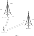
- FIG. 2 shows another application scenario according to an embodiment of the present invention.
- FIG. 2 includes a terminal device, a base station 1, and a base station 2.
- the base station 1 is provided with three cells, which are a cell 1, a cell 2, and a cell 3.
- the base station 2 is provided with two cells, which are a cell 4 and a cell 5.
- the cell 3 is a current serving cell of the terminal device. If the terminal device performs cell handover, the terminal device may hand over to the cell 1 or the cell 2, that is, perform intra-base station handover, or may hand over to the cell 4 or the cell 5, that is, perform inter-base station handover.
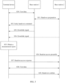
- FIG. 3 is a flowchart of a conditional handover method.
- a cell 1, a cell 2, or a cell 3 provided by a base station 1 is a serving cell of a terminal device before handover, and a cell 4 or a cell 5 provided by a base station 2 is a cell to which the terminal device can hand over.
- the terminal device exchanges some user data (User Data) with the base station 1. That is, the terminal device exchanges user data with the serving cell provided by the base station 1.
- User Data User Data
- the base station 1 may perform handover determining based on the user data.
- the handover determining herein is different from determining whether the terminal device performs cell handover described in the following portion of this specification. Instead, the handover determining may be understood as determining whether to send an early handover command (Early HO command) to the terminal device.
- the base station 1 and the base station 2 perform configuration and prepare for handover (Handover, HO).
- the base station 1 and the base station 2 perform active mode reference signal resource pre-configuration and handover preparation (Active mode Reference Signal resource pre-config and HO preparation).
- the base station 2 may notify the base station 1 of configuration information for handover of the terminal device.
- the base station 2 may further reserve a resource for the terminal device.
- the base station 1 sends the early handover command to the terminal device through the serving cell, and the terminal device receives the early handover command.
- the early handover command is used to instruct the terminal device to determine whether to perform cell handover. In other words, the terminal device knows, based on the early handover command, that the terminal device needs to determine whether to perform conditional handover.
- the base station 1 sends a downlink signal beam in an active mode to the terminal device, and the terminal device receives the reference signal beam. It may be understood that the base station 1 sends a downlink signal to the terminal device.
- the downlink signal sent by the base station 1 is, for example, a downlink reference signal.
- the base station 2 sends a downlink signal beam in an active mode to the terminal device, and the terminal device receives the reference signal beam. It may be understood that the base station 2 sends a downlink signal to the terminal device.
- the downlink signal sent by the base station 2 is, for example, a downlink reference signal.
- S33 may be performed before S34, or S33 is performed after S34, or S33 and S34 are simultaneously performed.
- the base station 2 may send a downlink signal to the terminal device, or may not send a downlink signal to the terminal device. Therefore, the arrow used to represent S34 in FIG. 3 is a dashed arrow.
- the terminal device obtains a measurement report of the reference signal in the active mode.
- the terminal device After receiving the downlink reference signal sent by the base station 1, the terminal device measures the downlink reference signal sent by the base station 1, to obtain a measurement report. Similarly, after receiving the downlink reference signal sent by the base station 2, the terminal device also measures the downlink reference signal sent by the base station 2, to obtain a measurement report. In this way, the terminal device obtains the measurement report of the reference signal in the active mode.
- the terminal device sends a random access preamble to the base station 2, to request to access the base station 2.
- the base station 2 receives the random access preamble.
- the terminal device After obtaining the measurement report, the terminal device determines, based on the measurement report and a handover condition, whether to perform cell handover. If the terminal device determines to perform cell handover, the terminal device performs S36.
- the base station 2 If the base station 2 agrees with the access of the terminal device, the base station 2 sends a random access response to the terminal device, and the terminal device receives the random access response.
- the terminal device exchanges some user data with the base station 2. That is, the terminal device exchanges user data with the new serving cell provided by the accessed base station 2.
- the terminal device sends a handover confirm (Handover confirm) to the base station 2, and the base station 2 receives the handover confirm.
- the terminal device autonomously determines whether to perform cell handover, and a disadvantage of such a handover manner is that a network side loses control over the terminal device.
- a disadvantage of such a handover manner is that a network side loses control over the terminal device.
- an example in which the terminal device determines whether to perform handover is used. However, if the terminal device determines not to perform handover, and the base station 2 reserves a resource for the terminal device, a waste of resources may be caused.
- an example useful for understanding the present invention provides a cell handover method.
- the terminal device can also perform measurement based on a downlink signal sent by the network device and/or a downlink signal sent by another network device.
- the terminal device can still measure a source cell and a target cell.
- the network device may still send a handover command to the terminal device. If the terminal device receives the handover command sent by the network device, the terminal device performs cell handover by executing the handover command.
- the network device can control the terminal device, and does not lose control over the terminal device even if the terminal device completely determines whether to perform handover.
- the network device may determine, after comprehensively considering various factors, whether to send the handover command to the terminal device, so that the terminal device can perform cell handover, thereby avoiding a waste of resources.
- FIG. 4 is a flowchart of the method.
- an example in which the method is applied to the application scenario shown in FIG. 1 or the application scenario shown in FIG. 2 is used, and an example in which a cell 1, a cell 2, or a cell 3 provided by a base station 1 is a serving cell of a terminal device before handover is used.
- S40 in the example shown in FIG. 4 refer to S30 in the example shown in FIG. 3 .
- S41 in the example shown in FIG. 4 refer to S31 in the example shown in FIG. 3 . Details are not described herein again. It should be noted that because S40 and S41 are not mandatory steps, to distinguish S40 and S41 from a mandatory step, the arrows used to represent the two steps in FIG. 4 are dashed arrows.
- the base station 1 sends an early handover command to the terminal device through the serving cell, and the terminal device receives the early handover command.
- the early handover command is used to instruct the terminal device to determine whether to perform cell handover.
- the terminal device knows, based on the early handover command, that the terminal device needs to determine whether to perform conditional handover.
- the early handover command may further carry a handover condition of the conditional handover, and the terminal device may perform determining based on the handover condition.
- the base station 1 may further send a handover cancel command to the terminal device, and the terminal device receives the handover cancel command.
- the step of sending the handover cancel command by the base station 1 to the terminal device may be performed at any moment after S42.
- the handover cancel command may be used to cancel the conditional handover configured by the early handover command, that is, cancel a function of determining, by the terminal device, whether the terminal device performs cell handover.
- the terminal device executes the handover cancel command, to cancel determining whether the terminal device performs cell handover, that is, cancel the conditional handover.
- the terminal device may stop measuring a downlink reference signal. This is equivalent to that the base station 1 completely determines whether the terminal device performs cell handover. Therefore, for example, if the base station 1 finds that a channel condition of the terminal device is getting better, the base station 1 may continue providing a service for the terminal device, and does not need to enable the terminal device to perform cell handover.
- S43 in the example shown in FIG. 4 refer to S33 in the example shown in FIG. 3 .
- S44 in the example shown in FIG. 4 refer to S34 in the example shown in FIG. 3 .
- S45 in the example shown in FIG. 4 refer to S35 in the example shown in FIG. 3 . Details are not described herein again. It should be noted that because S43 to S45 are not mandatory steps, to distinguish S43 to S45 from a mandatory step, the arrows used to represent the three steps in FIG. 4 are dashed arrows.
- the base station 1 performs handover determining. In other words, the base station 1 determines whether the terminal device performs cell handover.
- S46 is not a mandatory step. Therefore, to distinguish S46 from a mandatory step, the arrow used to represent S46 in FIG. 4 is a dashed arrow.
- a sequence of S46 and S43 to S45 are not limited in this specification.
- That the base station 1 performs handover determining includes, but is not limited to, the following manners:
- the base station 1 measures an uplink reference signal sent by the terminal device, to obtain a measurement report, and the base station 1 determines, based on the obtained measurement report, whether the terminal device performs cell handover.
- the base station 1 may first configure uplink measurement for the terminal device.
- the base station 1 sends uplink configuration information to the terminal device.
- the uplink configuration information is used to instruct the terminal device to send the uplink reference signal to the base station 1.
- the uplink configuration information indicates information such as a resource used by the terminal device to send the uplink reference signal and a period for sending the uplink reference signal.
- the terminal device sends the uplink reference signal to the base station 1 after receiving the uplink configuration information.
- the base station 1 may send the uplink configuration information to the terminal device in S42, to be specific, add the uplink configuration information to the early handover command for sending; or the base station 1 may send the uplink configuration information to the terminal device at another time, for example, before S42 or before S40, provided that the base station 1 completes sending the uplink configuration information to the terminal device before S46. If the base station 1 adds the uplink configuration information to the early handover command and sends the early handover command carrying the uplink configuration information to the terminal device, it is equivalent to that the base station 1 may start to perform uplink measurement after sending the early handover command. This reduces more resources occupied to send the uplink reference signal and perform measurement than performing uplink measurement from the beginning does.
- the terminal device sends a measurement report to the base station 1, and the base station 1 receives the measurement report sent by the terminal device, and determines, based on the received measurement report, whether the terminal device performs cell handover. Specifically, the terminal device measures the received downlink reference signal. For measurement performed by the terminal device on the downlink reference signal, refer to S43 and S44 in the example shown in FIG. 4 . After obtaining the measurement report, the terminal device may send the obtained measurement report to the base station 1. The base station 1 may first send measurement reporting information to the terminal device, and the measurement reporting information is used to instruct the terminal device to send the measurement report to the base station 1. After receiving the measurement reporting information, the terminal device sends the measurement report obtained by the terminal device to the base station 1.
- the base station 1 may send the measurement reporting information to the terminal device in S42, to be specific, add the measurement reporting information to the early handover command for sending; or the base station 1 may send the measurement reporting information to the terminal device at another time, for example, before S42 or before S40, provided that the base station 1 completes sending the measurement reporting information to the terminal device before S46. If the base station 1 sends the measurement reporting information to the terminal device before S42, the terminal device performs conditional determining after receiving the early handover command in S42.
- the terminal device may continue performing downlink measurement, that is, continue measuring a downlink reference signal sent by the base station 1 or another base station (for example, a base station 2), and may continue sending a newly obtained measurement report to the base station 1 based on a reporting condition of the measurement report. In this way, the base station 1 can conveniently obtain the latest measurement report in time, to more accurately determine whether the terminal device performs cell handover.
- the terminal device continuously measures the downlink reference signal. If the terminal device fails to perform handover when the base station instructs the terminal device to perform cell handover, the terminal device may further determine, based on the measurement report obtained by the terminal device, whether to perform cell handover, to ensure that the terminal device can complete handover when handover is required. Alternatively, in this case, the terminal device may stop performing downlink measurement, that is, cancel the process of measuring the downlink reference signal sent by the base station. In this way, consumption of the terminal device may be reduced.
- Such a manner may be understood as a determining manner based on implementation of the base station 1.
- the base station 1 sets a timer, and when the timer expires, the base station 1 triggers the terminal device to perform cell handover.
- the base station 1 may alternatively perform handover determining according the manner A or manner B described above. If before the timer expires, the base station 1 has already triggered, based on the determining in the manner A or the manner B, the terminal device to perform cell handover, the base station 1 may turn off the timer. If before the timer expires, the base station 1 has not triggered, based on the determining in the manner A or the manner B, the terminal device to perform cell handover, the base station 1 triggers, when the timer expires, the terminal device to perform cell handover.
- the base station 1 may not perform handover determining.
- the base station 1 does not determine whether the terminal device performs cell handover, and the base station 1 triggers, when the timer expires, the terminal device to perform cell handover.
- the base station performs handover determining.
- a determining result may be triggering the terminal device to perform cell handover, or may be determining that the terminal device does not perform cell handover.
- the terminal device basically performs cell handover for sure.
- the foregoing three handover determining manners may be selected based on situations.
- the base station 1 sends a handover command to the terminal device, and the terminal device receives the handover command.
- the handover command is used to instruct the terminal device to perform cell handover. That is, if the base station 1 determines, in the determining manner described in S46, that the terminal device performs cell handover, the base station 1 sends the handover command to the terminal device. If the terminal device that is performing conditional determining receives the handover command sent by the base station 1, the terminal device immediately executes the handover command, and starts to perform cell handover instead of performing conditional determining.
- the terminal device may stop measuring the downlink reference signal, that is, cancel measurement on the downlink reference signal, to reduce operations and computation of the terminal device by terminating the measurement process.
- the terminal device continues measuring the downlink reference signal even if the terminal device receives the handover command sent by the base station 1. In this way, if the terminal device fails to access the target cell according to the handover command, the terminal device may reselect, based on a downlink measurement report of the terminal device, a best cell for access.
- the terminal device waits for the handover command.
- the base station 1 has sent the handover cancel command to the terminal device according to the description in S42, and the terminal device has received the handover cancel command and canceled conditional handover configured by the early handover command.
- the terminal device can wait only for the handover command, because the terminal device cannot perform conditional determining by itself.
- the terminal device chooses to execute either of the conditional handover and the handover command that is triggered first. A delay may be reduced in this manner.
- the base station 1 does not send the handover cancel command to the terminal device according to the description in S42. For example, if the terminal device does not trigger cell handover in the conditional handover process, but the terminal device receives the handover command sent by the base station 1, the terminal device executes the handover command. In other words, the handover command arrives before the handover condition of the conditional handover is met. In this case, before S46, the handover condition of the conditional handover of the terminal device is not met yet.
- the terminal device triggers cell handover through a conditional handover process before receiving the handover command sent by the base station 1, the terminal device performs cell handover based on triggering of the conditional handover process.
- the handover condition of the conditional handover is already met before the handover command arrives.
- the base station 1 and the terminal device no longer perform S47.
- the terminal device starts conditional determining after S42, if the handover condition of the conditional handover is already met before the handover command arrives, where any one of moments at which steps S43 to S47 are performed may be a moment at which the handover condition is met, a step after the moment at which the handover condition is met is no longer performed. Instead, S48 to be described below is directly performed.
- the terminal device always waits for the handover command.
- the base station 1 does not send the handover cancel command to the terminal device according to the description in S42.
- the terminal device does not perform handover even if the handover condition of the conditional handover of the terminal device is already met. Instead, the terminal device waits for the handover command sent by the base station 1.
- the handover condition of the conditional handover of the terminal device may be met already, or may not be met yet. That is, the terminal device always waits for a notification of the base station.
- the terminal device Once receiving the handover command sent by the base station 1, the terminal device immediately performs handover. In this way, a network side can better control the terminal device, and factors such as uplink coverage, load, interference, and access policies of a serving base station and a neighboring base station may be comprehensively considered to control handover of the terminal device.
- the handover command sent by the base station 1 may carry a cell identifier.
- the cell identifier is determined by the base station 1 by measuring the uplink reference signal sent by the terminal device, and is a cell identifier of a cell to which the terminal device can hand over; or the cell identifier may be determined by another base station (for example, the base station 2) by measuring the uplink reference signal sent by the terminal device, and is a cell identifier of a cell to which the terminal device can hand over. If the cell identifier is obtained by the base station 2 through measurement, the base station 2 sends the obtained cell identifier to the base station 1, and the base station 1 may add, to the handover command, the received cell identifier sent by the base station 2.
- the terminal device executes the handover command, and hands over to the target cell indicated by the handover command.
- the terminal device may select one cell identifier from cell identifiers carried in the handover command as the cell identifier of the target cell, to hand over to the target cell.
- the terminal device may ignore the cell identifiers determined based on the conditional handover process. In other words, the terminal device preferentially performs handover based on an instruction of the base station 1.
- the handover command sent by the base station 1 may not carry a cell identifier.
- the base station 1 only instructs the terminal device to perform handover, but does not notify the terminal device of cells to which the terminal device can hand over. Therefore, after receiving the handover command, the terminal device may select the target cell based on the measurement report obtained by the terminal device, where the measurement report may be obtained by the terminal device by measuring the downlink reference signal sent by the base station 1 and/or another base station (for example, the base station 2).
- the base station 2 does not send the handover cancel command to the terminal device.
- Either of the cell indicated by the handover command or the cell determined by the terminal device based on the measurement report obtained by the terminal device may be a cell provided by the base station 1 or may be a cell provided by another base station (for example, the base station 2).
- the terminal device performs an access process.
- FIG. 4 an example in which the target cell of the terminal device is a cell provided by the base station 2 is used.
- the network side can control the terminal device even in the conditional handover process of the terminal device. For example, based on an actual network status, the base station may deliver the handover command before the terminal device obtains a conditional determining result, to trigger in advance the terminal device to perform handover, thereby shortening a handover delay.
- FIG. 4 how to strengthen control of the network side over the terminal device in the conditional handover process of the terminal device is mainly described.
- the following describes a cell handover method by using another example. In this example, how a terminal device selects a target cell is mainly described.
- FIG. 5 is a flowchart of the method. In the following description process, an example in which the method is applied to the application scenario shown in FIG. 1 or the application scenario shown in FIG. 2 is used, and an example in which a cell 1, a cell 2, or a cell 3 provided by a base station 1 is a serving cell of a terminal device before handover is used.
- the base station 1 sends uplink configuration information to the terminal device, and the terminal device receives the uplink configuration information.
- the uplink configuration information is used to instruct the terminal device to send an uplink reference signal to the base station 1.
- the uplink configuration information indicates information such as a resource used by the terminal device to send the uplink reference signal and a period for sending the uplink reference signal.
- the terminal device sends the uplink reference signal to the base station 1, and the base station 1 receives the uplink reference signal sent by the terminal device.
- the base station 1 may measure the uplink reference signal sent by the terminal device, to obtain a measurement report.
- the base station 1 may determine cell identifiers based on the obtained measurement report.
- the cell identifiers are cell identifiers of target cells to which the terminal device can hand over.
- the terminal device sends the uplink reference signal to a base station 2, and the base station 2 receives the uplink reference signal sent by the terminal device.
- the uplink reference signal that is received by the base station 2 and that is sent by the terminal device may be an uplink reference signal directly sent by the terminal device or an uplink reference signal that is received by the base station 2 from the base station 1 and that is sent by the terminal device.
- the base station 2 may measure the uplink reference signal sent by the terminal device, to obtain a measurement report.
- the uplink reference signal sent by the terminal device may also be received by another base station.
- the base station 2 also receives the uplink reference signal sent by the terminal device is used. If the base station 2 measures the uplink reference signal sent by the terminal device and obtains the measurement report, the base station 2 may send the obtained measurement report to the base station 1, or the base station 2 may send cell identifiers determined based on the measurement report obtained by the base station 2 to the base station 1.
- the cell identifiers are the cell identifiers of the target cells to which the terminal device can hand over.
- the arrow used to represent S52 in FIG. 5 is a dashed arrow.
- the terminal device exchanges some user data with the base station 1. That is, the terminal device exchanges user data with the serving cell provided by the base station 1.
- the base station 1 may perform handover determining based on the user data.
- the handover determining herein is different from determining whether the terminal device performs cell handover described in the following portion of this specification. Instead, the handover determining may be understood as determining whether to send an early handover command to the terminal device.
- the base station 1 and the base station 2 perform configuration and prepare for HO.
- the base station 1 and the base station 2 perform active mode reference signal resource pre-configuration and handover preparation.
- the base station 2 may notify the base station 1 of configuration information for handover of the terminal device.
- the base station 1 sends the early handover command to the terminal device through the serving cell, and the terminal device receives the early handover command.
- the early handover command is used to instruct the terminal device to determine whether to perform cell handover.
- the terminal device knows, based on the early handover command, that the terminal device needs to determine whether to perform conditional handover.
- the early handover command may further carry a handover condition of the conditional handover, and the terminal device may perform determining based on the handover condition.
- the early handover command may further carry the cell identifiers determined by the base station 1 and/or the cell identifiers determined by the base station 2.
- S56 in the example shown in FIG. 5 refer to S33 in the example shown in FIG. 3 .
- S57 in the example shown in FIG. 5 refer to S34 in the example shown in FIG. 3 .
- S58 in the example shown in FIG. 5 refer to S35 in the example shown in FIG. 3 . Details are not described herein again. It should be noted that because S56 and S57 are not mandatory steps, to distinguish S56 and S57 from a mandatory step, the arrows used to represent the two steps in FIG. 5 are dashed arrows.
- the terminal device performs an access process.
- FIG. 5 an example in which the target cell of the terminal device is a cell provided by the base station 2 is used.
- the terminal device hands over from the current serving cell to the target cell.
- the target cell is determined by the terminal device based on the measurement report obtained by the terminal device through measurement, and/or is determined by the terminal device based on the received cell identifiers sent by the base station 1.
- the terminal device may determine, based on the conditional handover, whether to perform cell handover. If the terminal device determines to perform cell handover, the terminal device determines the target cell based on the measurement report obtained by the terminal device through measurement and/or based on the received cell identifiers sent by the base station 1.
- the terminal device may determine, based on a handover command sent by the base station 1, to perform cell handover.
- the base station 1 determines, based on the measurement report obtained by the base station 1 and/or the received measurement report sent by the base station 2, that the terminal device needs to perform cell handover, and the base station 1 sends the handover command to the terminal device before S59, referring to S60 in FIG. 5 .
- the base station 1 already sends the cell identifiers to the terminal device by using the early handover command in S55, the base station 1 may no longer add the cell identifiers to the handover command.
- the arrow used to represent S60 in FIG. 5 is a dashed arrow.
- the terminal device may stop performing conditional determining, and immediately execute the handover command.
- the target cell is still determined based on the measurement report obtained by the terminal device through measurement and/or based on the received cell identifiers sent by the base station 1.
- this example also relates to two processes: the conditional handover and the handover that is notified of by the base station.
- the terminal device may choose to perform handover that is triggered first. For example, if the terminal device does not trigger cell handover in the conditional handover process, but the terminal device receives the handover command sent by the base station 1, the terminal device executes the handover command. Alternatively, if the terminal device triggers cell handover through a conditional handover process before receiving the handover command sent by the base station 1, the terminal device performs cell handover based on triggering of the conditional handover process.
- the terminal device may select a best cell, as the target cell, from cells whose cell identifiers are sent by the base station 1 and/or cells whose cell identifiers are determined by the terminal device, so that a selection range of the target cell is wider, and it is more helpful to select a cell having better performance.
- FIG. 4 how to strengthen control of the network side over the terminal device in the conditional handover process of the terminal device is mainly described.
- FIG. 5 how the terminal device selects the target cell is mainly described.
- FIG. 6 is a flowchart of the method. In the following description process, an example in which the method is applied to the application scenario shown in FIG. 1 or the application scenario shown in FIG.
- a cell 1, a cell 2, or a cell 3 provided by a base station 1 is a serving cell of a terminal device before handover, and a cell 4 or a cell 5 provided by a base station 2 is a target cell of the terminal device is used.
- S60 in the embodiment shown in FIG. 6 refer to S30 in the example shown in FIG. 3 .
- S61 in the embodiment shown in FIG. 6 refer to S31 in the example shown in FIG. 3 . Details are not described herein again. It should be noted that because S60 and S61 are not mandatory steps, to distinguish S60 and S61 from a mandatory step, the arrows used to represent the two steps in FIG. 6 are dashed arrows.
- the base station 1 sends an early handover command to the terminal device through the serving cell, and the terminal device receives the early handover command.
- the early handover command is used to instruct the terminal device to determine whether to perform cell handover.
- the terminal device knows, based on the early handover command, that the terminal device needs to determine whether to perform conditional handover.
- the early handover command may further carry a handover condition of the conditional handover, and the terminal device may perform determining based on the handover condition.
- S63 in the embodiment shown in FIG. 6 refer to S33 in the example shown in FIG. 3 .
- S64 in the embodiment shown in FIG. 6 refer to S34 in the example shown in FIG. 3 .
- S65 in the embodiment shown in FIG. 6 refer to S35 in the example shown in FIG. 3 . Details are not described herein again. It should be noted that because S63 to S65 are not mandatory steps, to distinguish S63 to S65 from a mandatory step, the arrows used to represent the three steps in FIG. 6 are dashed arrows.
- the base station 1 sends measurement reporting information to the terminal device through the serving cell, and the terminal device receives the measurement reporting information.
- the measurement reporting information is used to instruct the terminal device to send an obtained measurement report to the base station 1.
- the measurement reporting message may further carry a reporting condition of the measurement report, or a reporting condition of the measurement report may be determined by the terminal device, or may be determined based on a protocol or a standard.
- the terminal device sends the measurement report obtained by the terminal device to the base station 1 only when the reporting condition of the measurement report is met.
- a reporting condition of the measurement report is that the measurement report obtained by the terminal device continuously meets a measurement threshold within timer-to-trigger (Timer to trigger, TTT) duration.
- the following S67 is performed. If the handover condition carried in the early handover command is met before the reporting condition of the measurement report, or the handover condition carried in the early handover command and the reporting condition of the measurement report are simultaneously met, the following S68 is performed.
- S66 may be performed before S62, or may be performed at any time from S62 to S65, or may be performed after S65. This is not limited in this embodiment of the present invention.
- the terminal device sends the measurement report to the base station 1.
- the base station 1 may determine, based on the measurement report, whether the terminal device needs to perform cell handover.
- the terminal device hands over from the current serving cell to a target cell. That is, the terminal device performs an access process of accessing the base station 2. In this case, the terminal device performs cell handover based on a determining result of the conditional handover.
- the base station 1 and/or the terminal device may determine in time whether the terminal device performs cell handover, so that the terminal device may perform cell handover as soon as possible.
- FIG. 7 is a flowchart of the method. In the following description process, an example in which the method is applied to the application scenario shown in FIG. 1 or the application scenario shown in FIG.
- a cell 1, a cell 2, or a cell 3 provided by a base station 1 is a serving cell of a terminal device before handover, and a cell 4 or a cell 5 provided by a base station 2 is a target cell of the terminal device is used.
- the terminal device Before handing over to the base station 2, the terminal device sends an uplink reference signal to the base station 2, and the base station 2 receives the uplink reference signal sent by the terminal device.
- the serving cell of the terminal device is still a cell provided by the base station 1.
- the uplink reference signal that is received by the base station 2 and that is sent by the terminal device may be an uplink reference signal directly sent by the terminal device or an uplink reference signal that is received by the base station 2 from the base station 1 and that is sent by the terminal device.
- the base station 2 may obtain reference information based on the received uplink reference signal, where the reference information is used to indicate an uplink transmit power of the terminal device.
- the reference information obtained by the base station 2 may include an offset and/or an uplink path loss.
- the offset is an offset based on an initial transmit power of the terminal device.
- the base station 2 may determine the initial transmit power of the terminal device based on the received uplink reference signal.
- the base station 2 adds the offset to the initial transmit power.
- a sum of the initial transmit power and the offset may be used as an uplink transmit power of the terminal device after handover. Because the terminal device knows the initial transmit power of the terminal device, the base station 2 only needs to send the offset to the terminal device.
- PPRACH represents an uplink transmit power of the terminal device
- P CMAX represents a maximum transmit power of the terminal device
- PREAMBLE_RECEIVED_TARGET_POWER represents a target uplink receive power of the base station 2
- PL represents an uplink path loss (Pathloss)
- offset represents an offset.
- the uplink path loss is obtained by the base station 2 based on an initial transmit power for the uplink reference signal that is sent by the terminal device and that is received from the base station 1 and a receive power at which the base station 2 receives the uplink reference signal.
- P1 represents the initial transmit power at which the terminal device sends the uplink reference signal
- P2 represents a receive power at which the base station 2 receives the uplink reference signal.
- the terminal device also sends the uplink reference signal to the base station 1, and the base station 1 may also obtain the reference information based on the uplink reference signal sent by the terminal device. Details are not described herein.
- the base station 2 sends the obtained reference information to the base station 1, and the base station 1 receives the reference information sent by the base station 2.
- the base station 1 sends reference information to the terminal device, and the terminal device receives the reference information sent by the base station 1.
- the base station 1 sends the reference information to the terminal device by using an early handover command, or if the base station 1 sends a handover command to the terminal device, the base station 1 may send the reference information to the terminal device by using the handover command.
- the reference information sent by the base station 1 to the terminal device may include the reference information determined by the base station 1 and/or the reference information determined by the base station 2.
- the terminal device determines, based on the received reference information, an uplink transmit power at which the terminal device sends a message to the base station 2.
- the base station 2 can receive the message sent by the terminal device at the determined uplink transmit power. For example, when accessing the base station 2 through a random access process, the terminal device uses the determined uplink transmit power when sending the first message in the random access process, or the terminal device uses the determined uplink transmit power when sending the first scheduling-free message.
- a target cell may determine an uplink transmit power of the terminal device after the handover, so that the determined uplink transmit power is more accurate.
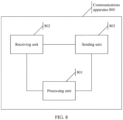
- FIG. 8 is a schematic structural diagram of a communications apparatus 800.
- the communications apparatus 800 may implement functions of the terminal device described above.
- the communications apparatus 800 may include a processing unit 801 and a receiving unit 802.
- the communications apparatus 800 may further include a sending unit 803.
- the processing unit 801 may be configured to perform S35 and S38 in the example shown in FIG. 3 , and S45 and S48 in the example shown in FIG. 4 , and/or configured to support another process of the technology described in this specification.
- the receiving unit 802 may be configured to perform S32, S33, and S34 in the example shown in FIG. 3 , and S42, S43, S44, and S47 in the example shown in FIG. 4 , and/or configured to support another process of the technology described in this specification.
- the sending unit 803 may be configured to perform S36 and S39 in the example shown in FIG. 3 , and/or configured to support another process of the technology described in this specification. All related content of the steps in the foregoing method examples may be cited in function descriptions of corresponding functional modules. Details are not described herein again.
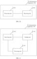
- FIG. 9 is a schematic structural diagram of a communications apparatus 900.
- the communications apparatus 900 may implement functions of the network device described above.
- the communications apparatus 900 may include a processing unit 901 and a sending unit 902.
- the communications apparatus 900 may further include a receiving unit 903.
- the processing unit 901 may be configured to perform S46 in the example shown in FIG. 4 , and/or configured to support another process of the technology described in this specification.
- the sending unit 902 may be configured to perform S32, S33, and S37 in the example shown in FIG. 3 , and S42 and S47 in the example shown in FIG. 4 , and/or configured to support another process of the technology described in this specification.
- the receiving unit 903 may be configured to perform S36 and S39 in the example shown in FIG. 3 , and/or configured to support another process of the technology described in this specification. All related content of the steps in the foregoing method examples may be cited in function descriptions of corresponding functional modules. Details are not described herein again.
- FIG. 10 is a schematic structural diagram of a communications apparatus 1000.
- the communications apparatus 1000 may implement functions of the terminal device described above.
- the communications apparatus 1000 may include a processing unit 1001 and a receiving unit 1002.
- the processing unit 1001 may be configured to perform S59 in the example shown in FIG. 5 , and/or configured to support another process of the technology described in this specification.
- the receiving unit 1002 may be configured to perform S55 and S60 in the example shown in FIG. 5 , and/or configured to support another process of the technology described in this specification. All related content of the steps in the foregoing method examples may be cited in function descriptions of corresponding functional modules. Details are not described herein again.
- FIG. 11 is a schematic structural diagram of a communications apparatus 1100.
- the communications apparatus 1100 may implement functions of the network device described above.
- the communications apparatus 1100 may include a processing unit 1101, a receiving unit 1102, and a sending unit 1103.
- the processing unit 1101 may be configured to perform S51 and S53 in the example shown in FIG. 5 , and/or configured to support another process of the technology described in this specification.
- the receiving unit 1102 may be configured to perform S51 in the example shown in FIG. 5 , and/or configured to support another process of the technology described in this specification.
- the sending unit 1103 may be configured to perform S55 and S60 in the example shown in FIG. 5 , and/or configured to support another process of the technology described in this specification. All related content of the steps in the foregoing method examples may be cited in function descriptions of corresponding functional modules.
- FIG. 12 is a schematic structural diagram of a communications apparatus 1200.
- the communications apparatus 1200 may implement functions of the network device described above.
- the communications apparatus 1200 may include a processing unit 1201 and a sending unit 1202.
- the communications apparatus 1200 further includes a receiving unit 1203.
- the processing unit 1201 may be configured to perform S72 in the embodiment shown in FIG. 7 , and/or configured to support another process of the technology described in this specification.
- the sending unit 1202 may be configured to perform S73 in the embodiment shown in FIG. 7 , and/or configured to support another process of the technology described in this specification.
- the receiving unit 1203 may be configured to perform S71 in the embodiment shown in FIG. 7 , and/or configured to support another process of the technology described in this specification. All related content of the steps in the foregoing method embodiments may be cited in function descriptions of corresponding functional modules. Details are not described herein again.
- FIG. 13 is a schematic structural diagram of a communications apparatus 1300.
- the communications apparatus 1300 may implement functions of the terminal device described above.
- the communications apparatus 1300 may include a processing unit 1301 and a receiving unit 1302.
- the communications apparatus 1300 further includes a sending unit 1303.
- the processing unit 1301 may be configured to perform S75 in the embodiment shown in FIG. 7 , and/or configured to support another process of the technology described in this specification.
- the receiving unit 1302 may be configured to perform S74 in the embodiment shown in FIG. 7 , and/or configured to support another process of the technology described in this specification.
- the sending unit 1303 may be configured to perform S71 in the embodiment shown in FIG. 7 , and/or configured to support another process of the technology described in this specification. All related content of the steps in the foregoing method embodiments may be cited in function descriptions of corresponding functional modules. Details are not described herein again.
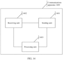
- FIG. 14 is a schematic structural diagram of a communications apparatus 1400.
- the communications apparatus 1400 may implement functions of the terminal device described above.
- the communications apparatus 1400 may include a sending unit 1401 and a receiving unit 1402.
- the communications apparatus 1400 further includes a processing unit 1403.
- the sending unit 1401 may be configured to perform S67 in the embodiment shown in FIG. 6 , and/or configured to support another process of the technology described in this specification.
- the receiving unit 1402 may be configured to perform S62 and S66 in the embodiment shown in FIG. 6 , and/or configured to support another process of the technology described in this specification.
- the processing unit 1403 may be configured to perform S68 in the embodiment shown in FIG. 6 , and/or configured to support another process of the technology described in this specification. All related content of the steps in the foregoing method embodiments may be cited in function descriptions of corresponding functional modules. Details are not described herein again.
- the communications apparatus 800 to the communications apparatus 1400 are presented in a form in which each functional module is defined in a correspondence to each function, or may be presented in a form in which each functional module is defined in an integrated manner.
- the "module” herein may be an application-specific integrated circuit (application-specific integrated circuit, ASIC), a processor and a memory for executing one or more software or firmware programs, an integrated logic circuit, and/or another component that can provide the foregoing function.
- any one of the communications apparatus 800 to the communications apparatus 1400 may be implemented by using a structure shown in FIG. 15 .
- a communications apparatus 1500 may include: a memory 1501, a processor 1502, a system bus 1503, and a communications interface 1504.
- the processor 1502, the memory 1501, and the communications interface 1504 are connected by using the system bus 1503.
- the memory 1501 is configured to store a computer-executable instruction.
- the processor 1502 executes the computer-executable instruction stored in the memory 1501, so that the communications apparatus 1500 performs the method provided in any one of the embodiment shown in FIG. 3 to the embodiment shown in FIG. 7 .
- the communications interface 1504 may be a transceiver, or may be an independent receiver and transmitter.
- the receiving unit 802 may correspond to the communications interface 1504 in FIG. 15 .
- the processing unit 801 may be built in or independent of the memory 1501 of the communications apparatus 1500 in a hardware/software form.
- the sending unit 902 may correspond to the communications interface 1504 in FIG. 15 .
- the processing unit 901 may be built in or independent of the memory 1501 of the communications apparatus 1500 in a hardware/software form.
- the receiving unit 1002 may correspond to the communications interface 1504 in FIG. 15 .
- the processing unit 1001 may be built in or independent of the memory 1501 of the communications apparatus 1500 in a hardware/software form.
- the receiving unit 1102 and the sending unit 1103 may correspond to the communications interface 1504 in FIG. 15 .
- the processing unit 1101 may be built in or independent of the memory 1501 of the communications apparatus 1500 in a hardware/software form.
- the sending unit 1202 may correspond to the communications interface 1504 in FIG. 15 .
- the processing unit 1201 may be built in or independent of the memory 1501 of the communications apparatus 1500 in a hardware/software form.
- the receiving unit 1302 may correspond to the communications interface 1504 in FIG. 15 .
- the processing unit 1301 may be built in or independent of the memory 1501 of the communications apparatus 1500 in a hardware/software form.
- the receiving unit 1402 and the sending unit 1401 may correspond to the communications interface 1504 in FIG. 15 .
- the processing unit 1403 may be built in or independent of the memory 1501 of the communications apparatus 1500 in a hardware/software form.
- the communications apparatus 1500 may be a field-programmable gate array (field-programmable gate array, FPGA), an application-specific integrated circuit (application-specific integrated circuit, ASIC), a system on chip (system on chip, SoC), or a central processing unit (central processing unit, CPU), a network processor (network processor, NP), a digital signal processor (digital signal processor, DSP), or a micro controller unit (micro controller unit, MCU), or a programmable logic device (programmable logic device, PLD) or another integrated chip may be used.
- the communications apparatus 1500 may be an independent network element, for example, a network device or a terminal device.
- the communications apparatus 800 to the communications apparatus 1400 provided in the embodiments of the present invention may be configured to perform the method provided in any one of the example shown in FIG. 3 to the embodiment shown in FIG. 7 , for technical effects that can be achieved by the communications apparatus 800 to the communications apparatus 1400, refer to the foregoing method embodiments. Details are not described herein again.
- the terminal device can also perform measurement based on the downlink signal sent by the network device and/or the downlink signal sent by the another network device. In other words, the terminal device can still measure the source cell and the target cell. However, the network device may still send the handover command to the terminal device. If the terminal device receives the handover command sent by the network device, the terminal device performs cell handover by executing the handover command. As can be learned, the network device can control the terminal device, and does not lose control over the terminal device even if the terminal device completely determines whether to perform handover.
- the network device may determine, after comprehensively considering various factors, whether to send the handover command to the terminal device, so that the terminal device can perform cell handover, thereby avoiding a waste of resource.
- These computer program instructions may be provided for a general-purpose computer, a dedicated computer, an embedded processor, or a processor of any other programmable data processing device to generate a machine, so that the instructions executed by a computer or a processor of any other programmable data processing device generate an apparatus for implementing a specific function in one or more procedures in the flowcharts and/or in one or more blocks in the block diagrams.
- All or some of the foregoing embodiments may be implemented by using software, hardware, firmware, or any combination thereof.
- the embodiments may be implemented completely or partially in a form of a computer program product.
- the computer program product includes one or more computer instructions.
- the computer may be a general-purpose computer, a dedicated computer, a computer network, or other programmable apparatuses.
- the computer instructions may be stored in a computer-readable storage medium or may be transmitted from a computer-readable storage medium to another readable storage medium.
- the computer instructions may be transmitted from a website, computer, server, or data center to another website, computer, server, or data center in a wired (for example, a coaxial cable, an optical fiber, or a digital subscriber line (DSL)) or wireless (for example, infrared, radio, or microwave) manner.
- the computer-readable storage medium may be any available medium accessible by a computer, or a data storage device, such as a server or a data center, integrating one or more available media.
- the available medium may be a magnetic medium (for example, a floppy disk, a hard disk, or a magnetic tape), an optical medium (for example, a DVD), a semiconductor medium (for example, a solid-state drive (Solid State Disk, SSD)), or the like.
- a magnetic medium for example, a floppy disk, a hard disk, or a magnetic tape
- an optical medium for example, a DVD
- a semiconductor medium for example, a solid-state drive (Solid State Disk, SSD)
Landscapes
- Engineering & Computer Science (AREA)
- Computer Networks & Wireless Communication (AREA)
- Signal Processing (AREA)
- Mobile Radio Communication Systems (AREA)
Claims (5)
- Verfahren für Zellen-Handover, umfassend:Empfangen (S32, S42, S55, S62) eines frühen Handover-Befehls von einer Netzwerkvorrichtung durch eine Endgerätvorrichtung, wobei die Netzwerkvorrichtung eine Basisstation beinhaltet, wobei der frühe Handover-Befehl verwendet wird, um die Endgerätvorrichtung anzuweisen, zu bestimmen, ob ein Zellen-Handover durchgeführt werden soll;Messen eines Downlink-Signals von der Netzwerkvorrichtung und/oder eines Downlink-Signals von einer anderen Netzwerkvorrichtung durch die Endgerätvorrichtung;Bestimmen, basierend auf einem erlangten Messbericht und einer Handover-Bedingung, die in dem früheren Handover-Befehl enthalten ist, ob Zellen-Handover durchgeführt werden soll, durch die Endgerätvorrichtung; undfalls die Endgerätvorrichtung basierend auf dem erlangten Messbericht und der Handover-Bedingung bestimmt, Zellen-Handover durchzuführen, Durchführen von Zellen-Handover durch die Endgerätvorrichtung gemäß der Bestimmung; undbevor die Endgerätvorrichtung basierend auf dem erlangten Messbericht und der Handover-Bedingung bestimmt, Zellen-Handover durchzuführen, und nach dem Empfangen des früheren Handover-Befehls und nach dem Messen des Downlink-Signals, das von der Netzwerkvorrichtung gesendet wird, und/oder eines Downlink-Signals, das von einer anderen Netzwerkvorrichtung gesendet wird:Empfangen (S66) von Messberichtsinformationen von der bedienenden Basisstation, welche die Endgerätvorrichtung anweisen, einen erlangten Messbericht an die bedienende Basisstation zu senden,falls die Meldebedingung des Messberichts vor der Handover-Bedingung, die in dem früheren Handover-Befehl enthalten ist, erfüllt ist, Senden (S67) des Messberichts, der durch Messen des Downlink-Signals von der Netzwerkvorrichtung und/oder des Downlink-Signals von der anderen Netzwerkvorrichtung erlangt wird, durch die Endgerätvorrichtung an die Netzwerkvorrichtung,falls die Handover-Bedingung, die in dem früheren Handover-Befehl enthalten ist, vor der Meldebedingung des Messberichts erfüllt ist oder die Handover-Bedingung, die in dem früheren Handover-Befehl enthalten ist, und die Meldebedingung des Messberichts gleichzeitig erfüllt sind, Handover (S68) von der aktuell bedienenden Zelle zu einer Zielzelle durch die Endgerätvorrichtung.
- Verfahren gemäß Anspruch 1, wobei das Verfahren ferner Folgendes umfasst:Empfangen (S70) von Uplink-Konfigurationsinformationen von der Netzwerkvorrichtung durch die Endgerätvorrichtung; undSenden (S71) eines Uplink-Referenzsignals an die Netzwerkvorrichtung basierend auf den Uplink-Konfigurationsinformationen durch die Endgerätvorrichtung, wobei das Uplink-Referenzsignal durch die Netzwerkvorrichtung verwendet wird, um zu bestimmen, ob es erforderlich ist, dass die Endgerätvorrichtung ein Zellen-Handover durchführt.
- Verfahren gemäß Anspruch 1, wobei die Zielzelle durch den Handover-Befehl angezeigt wird.
- Endgerätvorrichtung, die dazu konfiguriert ist, das Verfahren gemäß Anspruch 1-3 durchzuführen.
- Computerlesbares Speichermedium, umfassend Anweisungen, die, wenn sie durch einen Computer ausgeführt werden und auf einer Endgerätvorrichtung laufen, den Computer veranlassen, das Verfahren gemäß Anspruch 1-3 durchzuführen.
Priority Applications (1)
| Application Number | Priority Date | Filing Date | Title |
|---|---|---|---|
| EP24196183.8A EP4492867A3 (de) | 2017-04-28 | 2018-04-23 | Zellenübergabeverfahren, verfahren zur bestimmung der uplink-übertragungsleistung und vorrichtung |
Applications Claiming Priority (2)
| Application Number | Priority Date | Filing Date | Title |
|---|---|---|---|
| CN201710296457.5A CN108810960B (zh) | 2017-04-28 | 2017-04-28 | 一种小区切换、确定上行发送功率的方法及装置 |
| PCT/CN2018/084058 WO2018196710A1 (zh) | 2017-04-28 | 2018-04-23 | 一种小区切换、确定上行发送功率的方法及装置 |
Related Child Applications (2)
| Application Number | Title | Priority Date | Filing Date |
|---|---|---|---|
| EP24196183.8A Division EP4492867A3 (de) | 2017-04-28 | 2018-04-23 | Zellenübergabeverfahren, verfahren zur bestimmung der uplink-übertragungsleistung und vorrichtung |
| EP24196183.8A Division-Into EP4492867A3 (de) | 2017-04-28 | 2018-04-23 | Zellenübergabeverfahren, verfahren zur bestimmung der uplink-übertragungsleistung und vorrichtung |
Publications (3)
| Publication Number | Publication Date |
|---|---|
| EP3609224A1 EP3609224A1 (de) | 2020-02-12 |
| EP3609224A4 EP3609224A4 (de) | 2020-04-29 |
| EP3609224B1 true EP3609224B1 (de) | 2024-10-02 |
Family
ID=63918869
Family Applications (2)
| Application Number | Title | Priority Date | Filing Date |
|---|---|---|---|
| EP24196183.8A Pending EP4492867A3 (de) | 2017-04-28 | 2018-04-23 | Zellenübergabeverfahren, verfahren zur bestimmung der uplink-übertragungsleistung und vorrichtung |
| EP18790488.3A Active EP3609224B1 (de) | 2017-04-28 | 2018-04-23 | Verfahren und vorrichtungen für zellen-handover und zur bestimmung der übertragenen uplink-leistung |
Family Applications Before (1)
| Application Number | Title | Priority Date | Filing Date |
|---|---|---|---|
| EP24196183.8A Pending EP4492867A3 (de) | 2017-04-28 | 2018-04-23 | Zellenübergabeverfahren, verfahren zur bestimmung der uplink-übertragungsleistung und vorrichtung |
Country Status (4)
| Country | Link |
|---|---|
| US (1) | US11323943B2 (de) |
| EP (2) | EP4492867A3 (de) |
| CN (1) | CN108810960B (de) |
| WO (1) | WO2018196710A1 (de) |
Families Citing this family (27)
| Publication number | Priority date | Publication date | Assignee | Title |
|---|---|---|---|---|
| EP3738348A4 (de) * | 2018-01-08 | 2021-08-11 | Lenovo (Beijing) Limited | Verfahren und vorrichtung für ue-handover |
| CN110149663A (zh) * | 2018-02-13 | 2019-08-20 | 维沃移动通信有限公司 | 条件切换取消方法及通信设备 |
| WO2019157726A1 (zh) * | 2018-02-14 | 2019-08-22 | Oppo广东移动通信有限公司 | 资源上报的方法、终端设备和网络设备 |
| US12069521B2 (en) * | 2019-01-11 | 2024-08-20 | Nec Corporation | Radio access network node, radio terminal, and method therefor |
| CN111107593B (zh) * | 2019-01-23 | 2022-07-29 | 维沃移动通信有限公司 | 一种用于链路失败恢复的方法、用户侧设备和网络侧设备 |
| WO2020186464A1 (zh) * | 2019-03-19 | 2020-09-24 | Oppo广东移动通信有限公司 | 一种小区切换的处理方法、设备及存储介质 |
| CN112087755B (zh) | 2019-06-14 | 2022-06-14 | 华为技术有限公司 | 一种小区切换方法、通信装置及系统 |
| EP4734612A2 (de) * | 2019-06-14 | 2026-04-29 | Xiaomi Communications Co., Ltd. | Aufbau einer aggregierten verbindung |
| CN112105064B (zh) * | 2019-06-17 | 2022-09-13 | 中国移动通信有限公司研究院 | 切换方法、指示方法、终端及网络侧设备 |
| WO2021003701A1 (zh) * | 2019-07-10 | 2021-01-14 | 北京小米移动软件有限公司 | 信息发送方法、接收方法、装置、设备及存储介质 |
| CN112243274B (zh) * | 2019-07-17 | 2021-10-22 | 大唐移动通信设备有限公司 | 一种基于时间的定时切换处理方法及装置 |
| EP4005271B1 (de) | 2019-07-30 | 2025-03-26 | Nokia Solutions and Networks Oy | Benutzergeräteprotokollierung während der übergabe |
| CN114175726B (zh) * | 2019-07-30 | 2024-01-26 | 中兴通讯股份有限公司 | 用于移动性控制的无线通信方法 |
| WO2021035730A1 (zh) | 2019-08-30 | 2021-03-04 | 华为技术有限公司 | 一种通信方法及装置 |
| EP4462879A3 (de) | 2019-10-01 | 2025-01-15 | InterDigital Patent Holdings, Inc. | Bedingte mobilität mit multikonnektivität |
| CN112788723B (zh) | 2019-11-08 | 2022-08-09 | 华为技术有限公司 | 功率控制的方法和装置 |
| CN114830725B (zh) * | 2019-12-25 | 2025-06-10 | 华为技术有限公司 | 一种通信方法及设备 |
| CN117715166A (zh) | 2020-06-22 | 2024-03-15 | 华为技术有限公司 | 功率控制方法及装置 |
| CN111786764B (zh) * | 2020-06-30 | 2022-08-26 | 中国联合网络通信集团有限公司 | 主载波选择方法、系统、终端设备及计算机可读存储介质 |
| CN114339713B (zh) * | 2020-09-29 | 2023-07-14 | 维沃移动通信有限公司 | 传输处理方法、终端及网络侧设备 |
| CN116250294B (zh) * | 2020-10-15 | 2026-01-13 | 华为技术有限公司 | 功率控制方法、装置及系统 |
| CN116368895A (zh) * | 2020-12-24 | 2023-06-30 | 中兴通讯股份有限公司 | 用于请求参考信号的系统和方法 |
| WO2022165212A1 (en) * | 2021-01-29 | 2022-08-04 | Innopeak Technology, Inc. | Method and apparatus for selective enablement or disablement of measurement report during call setup |
| EP4289176A4 (de) * | 2021-02-03 | 2025-04-09 | Nokia Technologies Oy | Überlebenszeitabhängige flexible übergabeausführung |
| WO2023027311A1 (ko) * | 2021-08-25 | 2023-03-02 | 엘지전자 주식회사 | 무선 통신 시스템에서 핸드오버를 수행하기 위한 장치 및 방법 |
| CN117135654B (zh) * | 2023-02-14 | 2024-06-04 | 荣耀终端有限公司 | 语音业务的建立方法和电子设备 |
| WO2026006091A1 (en) * | 2024-06-29 | 2026-01-02 | Ofinno, Llc | Default uplink transmission power for conditional layer-1/layer-2 triggered mobility |
Citations (1)
| Publication number | Priority date | Publication date | Assignee | Title |
|---|---|---|---|---|
| EP3738348A1 (de) * | 2018-01-08 | 2020-11-18 | Lenovo (Beijing) Limited | Verfahren und vorrichtung für ue-handover |
Family Cites Families (14)
| Publication number | Priority date | Publication date | Assignee | Title |
|---|---|---|---|---|
| CN101453745B (zh) * | 2007-11-29 | 2012-09-19 | 电信科学技术研究院 | 一种小区切换过程中的测量方法、透明中继及基站 |
| CN101873657B (zh) * | 2009-04-23 | 2014-12-10 | 中兴通讯股份有限公司 | 一种估算邻区上行信号质量的方法和切换优化方法 |
| CN101932052B (zh) * | 2009-06-23 | 2016-08-24 | 华为技术有限公司 | 一种切换方法、用户终端及网络侧设备 |
| US9591545B2 (en) * | 2011-08-12 | 2017-03-07 | Panasonic Intellectual Property Corporation Of America | Handover control method, wireless communication terminal, and wireless communication device |
| KR101571878B1 (ko) * | 2012-12-14 | 2015-12-04 | 주식회사 케이티 | 핸드오버 제어 방법 |
| EP2950587A4 (de) * | 2013-01-25 | 2016-07-27 | Fujitsu Ltd | Weiterleitungsverfahren auf basis eines uplink-signals, verfahren zum konfigurieren eines uplink-signals, benutzervorrichtung und basisstation |
| US9749926B2 (en) * | 2013-03-15 | 2017-08-29 | Telefonaktiebolaget Lm Ericsson (Publ) | Methods and apparatuses for configuring a wireless device to evaluate handover events |
| US9578583B2 (en) * | 2013-08-12 | 2017-02-21 | Telefonaktiebolaget Lm Ericsson (Publ) | Handover improvement for high speed user equipment in LTE |
| WO2015032091A1 (zh) * | 2013-09-09 | 2015-03-12 | 华为技术有限公司 | 小区的切换方法、终端和网络设备 |
| CN104202758B (zh) * | 2014-09-04 | 2018-01-26 | 北京北方烽火科技有限公司 | 小区联合调度方法及装置 |
| US9398509B1 (en) * | 2015-01-07 | 2016-07-19 | Verizon Patent And Licensing Inc. | Dynamic hand-over parameter control |
| CN106454961B (zh) * | 2015-08-07 | 2019-11-15 | 中国电信股份有限公司 | 用于灵活带宽的小区切换方法、系统以及设备 |
| CN106454876B (zh) * | 2015-08-07 | 2019-11-15 | 中国电信股份有限公司 | 用于灵活带宽的小区测量方法、系统以及设备 |
| CN105101247B (zh) * | 2015-09-01 | 2018-08-03 | 重庆邮电大学 | 基于切换类型特定权重的移动状态估计增强方法及装置 |
-
2017
- 2017-04-28 CN CN201710296457.5A patent/CN108810960B/zh active Active
-
2018
- 2018-04-23 WO PCT/CN2018/084058 patent/WO2018196710A1/zh not_active Ceased
- 2018-04-23 EP EP24196183.8A patent/EP4492867A3/de active Pending
- 2018-04-23 EP EP18790488.3A patent/EP3609224B1/de active Active
-
2019
- 2019-10-25 US US16/664,451 patent/US11323943B2/en active Active
Patent Citations (1)
| Publication number | Priority date | Publication date | Assignee | Title |
|---|---|---|---|---|
| EP3738348A1 (de) * | 2018-01-08 | 2020-11-18 | Lenovo (Beijing) Limited | Verfahren und vorrichtung für ue-handover |
Also Published As
| Publication number | Publication date |
|---|---|
| CN108810960B (zh) | 2021-06-22 |
| WO2018196710A1 (zh) | 2018-11-01 |
| EP4492867A2 (de) | 2025-01-15 |
| EP4492867A3 (de) | 2025-04-16 |
| EP3609224A4 (de) | 2020-04-29 |
| CN108810960A (zh) | 2018-11-13 |
| US11323943B2 (en) | 2022-05-03 |
| US20200059847A1 (en) | 2020-02-20 |
| EP3609224A1 (de) | 2020-02-12 |
Similar Documents
| Publication | Publication Date | Title |
|---|---|---|
| US11323943B2 (en) | Cell handover method, method for determining uplink transmit power, and apparatus | |
| EP3796729B1 (de) | Iab-knotenvermittlungsverfahren, iab-knoten, donator-basisstation und computerprogrammprodukt | |
| US12627990B2 (en) | UE capability information processing method and apparatus, device, and storage medium | |
| US12302154B2 (en) | UE power saving mechanism under early measurement reporting | |
| US20240064718A1 (en) | Communication method, base station, terminal, and storage medium | |
| US9578560B1 (en) | Systems and methods for managing network connections | |
| US20210321306A1 (en) | First network node, wireless device and methods performed thereby for handling a link switch | |
| US20210306968A1 (en) | Timing advance change detection | |
| CN105228198B (zh) | 小区测量处理方法、装置、终端及基站 | |
| EP2962489B1 (de) | Lieferung von messungen | |
| EP3073788B1 (de) | Verfahren und system zur auswahl einer netzwerkseitigen zielvorrichtung | |
| US12069605B2 (en) | First wireless device, first network node, second wireless device, and methods performed thereby, for determining a status of a cell | |
| US20240323739A1 (en) | Communication method and communication apparatus | |
| CN111543082A (zh) | 小区配置装置及方法 | |
| US11395206B2 (en) | Measurement configuration | |
| EP3499947B1 (de) | Ressourcenverwaltungsanzeigeverfahren und -vorrichtung | |
| JP7737559B2 (ja) | 5gニューラジオモビリティ拡張 | |
| EP2943010A1 (de) | Näherungserkennungs- und -messverfahren für frequenzübergreifende nachbarzellen, funknetzsteuerung und benutzervorrichtung | |
| US12010628B2 (en) | Power-efficient measurement reporting for multi/dual connectivity in cellular communication networks | |
| WO2024026897A1 (zh) | 信息处理方法、信息发送方法和装置 | |
| US20230089106A1 (en) | Systems and methods for operating during a transition phase when a wireless device transitions between operational scenarios | |
| US9813974B2 (en) | Information reporting method, information receiving method, UE and network device | |
| JP7818737B2 (ja) | 通信方法及び通信装置 | |
| US12477613B2 (en) | Filtering of layer 1 beam measurements for L1/2 inter-cell mobility | |
| JP2014192738A (ja) | 無線通信装置及びその制御方法、並びに制御装置及びその制御方法 |
Legal Events
| Date | Code | Title | Description |
|---|---|---|---|
| STAA | Information on the status of an ep patent application or granted ep patent |
Free format text: STATUS: THE INTERNATIONAL PUBLICATION HAS BEEN MADE |
|
| PUAI | Public reference made under article 153(3) epc to a published international application that has entered the european phase |
Free format text: ORIGINAL CODE: 0009012 |
|
| STAA | Information on the status of an ep patent application or granted ep patent |
Free format text: STATUS: REQUEST FOR EXAMINATION WAS MADE |
|
| 17P | Request for examination filed |
Effective date: 20191108 |
|
| AK | Designated contracting states |
Kind code of ref document: A1 Designated state(s): AL AT BE BG CH CY CZ DE DK EE ES FI FR GB GR HR HU IE IS IT LI LT LU LV MC MK MT NL NO PL PT RO RS SE SI SK SM TR |
|
| AX | Request for extension of the european patent |
Extension state: BA ME |
|
| A4 | Supplementary search report drawn up and despatched |
Effective date: 20200331 |
|
| RIC1 | Information provided on ipc code assigned before grant |
Ipc: H04W 36/34 20090101ALI20200325BHEP Ipc: H04W 24/10 20090101AFI20200325BHEP Ipc: H04W 36/00 20090101ALI20200325BHEP |
|
| DAV | Request for validation of the european patent (deleted) | ||
| DAX | Request for extension of the european patent (deleted) | ||
| STAA | Information on the status of an ep patent application or granted ep patent |
Free format text: STATUS: EXAMINATION IS IN PROGRESS |
|
| 17Q | First examination report despatched |
Effective date: 20210824 |
|
| REG | Reference to a national code |
Ref country code: DE Free format text: PREVIOUS MAIN CLASS: H04W0024100000 Ipc: H04W0036000000 Ref country code: DE Ref legal event code: R079 Ref document number: 602018074981 Country of ref document: DE Free format text: PREVIOUS MAIN CLASS: H04W0024100000 Ipc: H04W0036000000 |
|
| RIC1 | Information provided on ipc code assigned before grant |
Ipc: H04W 36/34 20090101ALI20240307BHEP Ipc: H04W 36/00 20090101AFI20240307BHEP |
|
| GRAP | Despatch of communication of intention to grant a patent |
Free format text: ORIGINAL CODE: EPIDOSNIGR1 |
|
| STAA | Information on the status of an ep patent application or granted ep patent |
Free format text: STATUS: GRANT OF PATENT IS INTENDED |
|
| INTG | Intention to grant announced |
Effective date: 20240502 |
|
| GRAS | Grant fee paid |
Free format text: ORIGINAL CODE: EPIDOSNIGR3 |
|
| GRAA | (expected) grant |
Free format text: ORIGINAL CODE: 0009210 |
|
| STAA | Information on the status of an ep patent application or granted ep patent |
Free format text: STATUS: THE PATENT HAS BEEN GRANTED |
|
| AK | Designated contracting states |
Kind code of ref document: B1 Designated state(s): AL AT BE BG CH CY CZ DE DK EE ES FI FR GB GR HR HU IE IS IT LI LT LU LV MC MK MT NL NO PL PT RO RS SE SI SK SM TR |
|
| P01 | Opt-out of the competence of the unified patent court (upc) registered |
Free format text: CASE NUMBER: APP_48752/2024 Effective date: 20240827 |
|
| REG | Reference to a national code |
Ref country code: GB Ref legal event code: FG4D |
|
| REG | Reference to a national code |
Ref country code: CH Ref legal event code: EP |
|
| REG | Reference to a national code |
Ref country code: DE Ref legal event code: R096 Ref document number: 602018074981 Country of ref document: DE |
|
| REG | Reference to a national code |
Ref country code: IE Ref legal event code: FG4D |
|
| REG | Reference to a national code |
Ref country code: LT Ref legal event code: MG9D |
|
| REG | Reference to a national code |
Ref country code: NL Ref legal event code: MP Effective date: 20241002 |
|
| REG | Reference to a national code |
Ref country code: AT Ref legal event code: MK05 Ref document number: 1729368 Country of ref document: AT Kind code of ref document: T Effective date: 20241002 |
|
| PG25 | Lapsed in a contracting state [announced via postgrant information from national office to epo] |
Ref country code: NL Free format text: LAPSE BECAUSE OF FAILURE TO SUBMIT A TRANSLATION OF THE DESCRIPTION OR TO PAY THE FEE WITHIN THE PRESCRIBED TIME-LIMIT Effective date: 20241002 |
|
| PG25 | Lapsed in a contracting state [announced via postgrant information from national office to epo] |
Ref country code: NL Free format text: LAPSE BECAUSE OF FAILURE TO SUBMIT A TRANSLATION OF THE DESCRIPTION OR TO PAY THE FEE WITHIN THE PRESCRIBED TIME-LIMIT Effective date: 20241002 |
|
| PG25 | Lapsed in a contracting state [announced via postgrant information from national office to epo] |
Ref country code: IS Free format text: LAPSE BECAUSE OF FAILURE TO SUBMIT A TRANSLATION OF THE DESCRIPTION OR TO PAY THE FEE WITHIN THE PRESCRIBED TIME-LIMIT Effective date: 20250202 Ref country code: PT Free format text: LAPSE BECAUSE OF FAILURE TO SUBMIT A TRANSLATION OF THE DESCRIPTION OR TO PAY THE FEE WITHIN THE PRESCRIBED TIME-LIMIT Effective date: 20250203 Ref country code: HR Free format text: LAPSE BECAUSE OF FAILURE TO SUBMIT A TRANSLATION OF THE DESCRIPTION OR TO PAY THE FEE WITHIN THE PRESCRIBED TIME-LIMIT Effective date: 20241002 |
|
| PG25 | Lapsed in a contracting state [announced via postgrant information from national office to epo] |
Ref country code: FI Free format text: LAPSE BECAUSE OF FAILURE TO SUBMIT A TRANSLATION OF THE DESCRIPTION OR TO PAY THE FEE WITHIN THE PRESCRIBED TIME-LIMIT Effective date: 20241002 |
|
| PG25 | Lapsed in a contracting state [announced via postgrant information from national office to epo] |
Ref country code: BG Free format text: LAPSE BECAUSE OF FAILURE TO SUBMIT A TRANSLATION OF THE DESCRIPTION OR TO PAY THE FEE WITHIN THE PRESCRIBED TIME-LIMIT Effective date: 20241002 |
|
| PG25 | Lapsed in a contracting state [announced via postgrant information from national office to epo] |
Ref country code: ES Free format text: LAPSE BECAUSE OF FAILURE TO SUBMIT A TRANSLATION OF THE DESCRIPTION OR TO PAY THE FEE WITHIN THE PRESCRIBED TIME-LIMIT Effective date: 20241002 |
|
| PG25 | Lapsed in a contracting state [announced via postgrant information from national office to epo] |
Ref country code: NO Free format text: LAPSE BECAUSE OF FAILURE TO SUBMIT A TRANSLATION OF THE DESCRIPTION OR TO PAY THE FEE WITHIN THE PRESCRIBED TIME-LIMIT Effective date: 20250102 |
|
| PG25 | Lapsed in a contracting state [announced via postgrant information from national office to epo] |
Ref country code: LV Free format text: LAPSE BECAUSE OF FAILURE TO SUBMIT A TRANSLATION OF THE DESCRIPTION OR TO PAY THE FEE WITHIN THE PRESCRIBED TIME-LIMIT Effective date: 20241002 Ref country code: AT Free format text: LAPSE BECAUSE OF FAILURE TO SUBMIT A TRANSLATION OF THE DESCRIPTION OR TO PAY THE FEE WITHIN THE PRESCRIBED TIME-LIMIT Effective date: 20241002 Ref country code: GR Free format text: LAPSE BECAUSE OF FAILURE TO SUBMIT A TRANSLATION OF THE DESCRIPTION OR TO PAY THE FEE WITHIN THE PRESCRIBED TIME-LIMIT Effective date: 20250103 |
|
| PG25 | Lapsed in a contracting state [announced via postgrant information from national office to epo] |
Ref country code: CZ Free format text: LAPSE BECAUSE OF FAILURE TO SUBMIT A TRANSLATION OF THE DESCRIPTION OR TO PAY THE FEE WITHIN THE PRESCRIBED TIME-LIMIT Effective date: 20241002 Ref country code: PL Free format text: LAPSE BECAUSE OF FAILURE TO SUBMIT A TRANSLATION OF THE DESCRIPTION OR TO PAY THE FEE WITHIN THE PRESCRIBED TIME-LIMIT Effective date: 20241002 |
|
| PG25 | Lapsed in a contracting state [announced via postgrant information from national office to epo] |
Ref country code: RS Free format text: LAPSE BECAUSE OF FAILURE TO SUBMIT A TRANSLATION OF THE DESCRIPTION OR TO PAY THE FEE WITHIN THE PRESCRIBED TIME-LIMIT Effective date: 20250102 |
|
| PG25 | Lapsed in a contracting state [announced via postgrant information from national office to epo] |
Ref country code: SM Free format text: LAPSE BECAUSE OF FAILURE TO SUBMIT A TRANSLATION OF THE DESCRIPTION OR TO PAY THE FEE WITHIN THE PRESCRIBED TIME-LIMIT Effective date: 20241002 |
|
| REG | Reference to a national code |
Ref country code: DE Ref legal event code: R097 Ref document number: 602018074981 Country of ref document: DE |
|
| PGFP | Annual fee paid to national office [announced via postgrant information from national office to epo] |
Ref country code: DE Payment date: 20250305 Year of fee payment: 8 |
|
| PG25 | Lapsed in a contracting state [announced via postgrant information from national office to epo] |
Ref country code: DK Free format text: LAPSE BECAUSE OF FAILURE TO SUBMIT A TRANSLATION OF THE DESCRIPTION OR TO PAY THE FEE WITHIN THE PRESCRIBED TIME-LIMIT Effective date: 20241002 |
|
| PG25 | Lapsed in a contracting state [announced via postgrant information from national office to epo] |
Ref country code: EE Free format text: LAPSE BECAUSE OF FAILURE TO SUBMIT A TRANSLATION OF THE DESCRIPTION OR TO PAY THE FEE WITHIN THE PRESCRIBED TIME-LIMIT Effective date: 20241002 |
|
| PG25 | Lapsed in a contracting state [announced via postgrant information from national office to epo] |
Ref country code: RO Free format text: LAPSE BECAUSE OF FAILURE TO SUBMIT A TRANSLATION OF THE DESCRIPTION OR TO PAY THE FEE WITHIN THE PRESCRIBED TIME-LIMIT Effective date: 20241002 |
|
| PG25 | Lapsed in a contracting state [announced via postgrant information from national office to epo] |
Ref country code: SK Free format text: LAPSE BECAUSE OF FAILURE TO SUBMIT A TRANSLATION OF THE DESCRIPTION OR TO PAY THE FEE WITHIN THE PRESCRIBED TIME-LIMIT Effective date: 20241002 |
|
| PG25 | Lapsed in a contracting state [announced via postgrant information from national office to epo] |
Ref country code: IT Free format text: LAPSE BECAUSE OF FAILURE TO SUBMIT A TRANSLATION OF THE DESCRIPTION OR TO PAY THE FEE WITHIN THE PRESCRIBED TIME-LIMIT Effective date: 20241002 |
|
| PLBE | No opposition filed within time limit |
Free format text: ORIGINAL CODE: 0009261 |
|
| STAA | Information on the status of an ep patent application or granted ep patent |
Free format text: STATUS: NO OPPOSITION FILED WITHIN TIME LIMIT |
|
| PG25 | Lapsed in a contracting state [announced via postgrant information from national office to epo] |
Ref country code: SE Free format text: LAPSE BECAUSE OF FAILURE TO SUBMIT A TRANSLATION OF THE DESCRIPTION OR TO PAY THE FEE WITHIN THE PRESCRIBED TIME-LIMIT Effective date: 20241002 |
|
| 26N | No opposition filed |
Effective date: 20250703 |
|
| REG | Reference to a national code |
Ref country code: CH Ref legal event code: H13 Free format text: ST27 STATUS EVENT CODE: U-0-0-H10-H13 (AS PROVIDED BY THE NATIONAL OFFICE) Effective date: 20251125 |
|
| PG25 | Lapsed in a contracting state [announced via postgrant information from national office to epo] |
Ref country code: LU Free format text: LAPSE BECAUSE OF NON-PAYMENT OF DUE FEES Effective date: 20250423 |
|
| PG25 | Lapsed in a contracting state [announced via postgrant information from national office to epo] |
Ref country code: MC Free format text: LAPSE BECAUSE OF FAILURE TO SUBMIT A TRANSLATION OF THE DESCRIPTION OR TO PAY THE FEE WITHIN THE PRESCRIBED TIME-LIMIT Effective date: 20241002 |
|
| PG25 | Lapsed in a contracting state [announced via postgrant information from national office to epo] |
Ref country code: FR Free format text: LAPSE BECAUSE OF NON-PAYMENT OF DUE FEES Effective date: 20250430 |
|
| PG25 | Lapsed in a contracting state [announced via postgrant information from national office to epo] |
Ref country code: CH Free format text: LAPSE BECAUSE OF NON-PAYMENT OF DUE FEES Effective date: 20250430 |
|
| PGFP | Annual fee paid to national office [announced via postgrant information from national office to epo] |
Ref country code: GB Payment date: 20260312 Year of fee payment: 9 |
|
| PG25 | Lapsed in a contracting state [announced via postgrant information from national office to epo] |
Ref country code: IE Free format text: LAPSE BECAUSE OF NON-PAYMENT OF DUE FEES Effective date: 20250423 |
|
| PGFP | Annual fee paid to national office [announced via postgrant information from national office to epo] |
Ref country code: BE Payment date: 20260317 Year of fee payment: 9 |