EP3609034A1 - Transferverfahren ohne überlappung der stromquellen, und quellenumschalter, der dieses verfahren anwendet - Google Patents
Transferverfahren ohne überlappung der stromquellen, und quellenumschalter, der dieses verfahren anwendet Download PDFInfo
- Publication number
- EP3609034A1 EP3609034A1 EP19180775.9A EP19180775A EP3609034A1 EP 3609034 A1 EP3609034 A1 EP 3609034A1 EP 19180775 A EP19180775 A EP 19180775A EP 3609034 A1 EP3609034 A1 EP 3609034A1
- Authority
- EP
- European Patent Office
- Prior art keywords
- source
- switch
- closing
- time
- opening
- Prior art date
- Legal status (The legal status is an assumption and is not a legal conclusion. Google has not performed a legal analysis and makes no representation as to the accuracy of the status listed.)
- Granted
Links
- 238000000034 method Methods 0.000 title claims abstract description 53
- 238000011084 recovery Methods 0.000 title description 2
- 238000012546 transfer Methods 0.000 claims abstract description 71
- 101100207042 Caenorhabditis elegans unc-94 gene Proteins 0.000 claims description 30
- 101100207005 Caenorhabditis elegans tmc-2 gene Proteins 0.000 claims description 29
- 230000007246 mechanism Effects 0.000 claims description 19
- 238000011144 upstream manufacturing Methods 0.000 claims description 9
- 101100425646 Caenorhabditis elegans tmc-1 gene Proteins 0.000 claims description 4
- 238000012545 processing Methods 0.000 claims description 3
- 238000010586 diagram Methods 0.000 description 12
- 238000010616 electrical installation Methods 0.000 description 8
- 238000005259 measurement Methods 0.000 description 7
- 230000008569 process Effects 0.000 description 5
- 238000009434 installation Methods 0.000 description 4
- 230000004913 activation Effects 0.000 description 2
- 230000008034 disappearance Effects 0.000 description 2
- 238000004519 manufacturing process Methods 0.000 description 2
- 230000001360 synchronised effect Effects 0.000 description 2
- 238000012360 testing method Methods 0.000 description 2
- -1 Tmd2 Proteins 0.000 description 1
- 230000002159 abnormal effect Effects 0.000 description 1
- 230000002238 attenuated effect Effects 0.000 description 1
- 230000007423 decrease Effects 0.000 description 1
- 230000003111 delayed effect Effects 0.000 description 1
- 230000000694 effects Effects 0.000 description 1
- 235000021183 entrée Nutrition 0.000 description 1
- 230000002349 favourable effect Effects 0.000 description 1
- 230000003993 interaction Effects 0.000 description 1
- 238000012423 maintenance Methods 0.000 description 1
- SYHGEUNFJIGTRX-UHFFFAOYSA-N methylenedioxypyrovalerone Chemical compound C=1C=C2OCOC2=CC=1C(=O)C(CCC)N1CCCC1 SYHGEUNFJIGTRX-UHFFFAOYSA-N 0.000 description 1
- 238000013021 overheating Methods 0.000 description 1
- 238000012163 sequencing technique Methods 0.000 description 1
- 230000007704 transition Effects 0.000 description 1
- 230000002747 voluntary effect Effects 0.000 description 1
Images


Classifications
-
- H—ELECTRICITY
- H02—GENERATION; CONVERSION OR DISTRIBUTION OF ELECTRIC POWER
- H02J—CIRCUIT ARRANGEMENTS OR SYSTEMS FOR SUPPLYING OR DISTRIBUTING ELECTRIC POWER; SYSTEMS FOR STORING ELECTRIC ENERGY
- H02J9/00—Circuit arrangements for emergency or stand-by power supply, e.g. for emergency lighting
- H02J9/04—Circuit arrangements for emergency or stand-by power supply, e.g. for emergency lighting in which the distribution system is disconnected from the normal source and connected to a standby source
- H02J9/06—Circuit arrangements for emergency or stand-by power supply, e.g. for emergency lighting in which the distribution system is disconnected from the normal source and connected to a standby source with automatic change-over, e.g. UPS systems
- H02J9/061—Circuit arrangements for emergency or stand-by power supply, e.g. for emergency lighting in which the distribution system is disconnected from the normal source and connected to a standby source with automatic change-over, e.g. UPS systems for DC powered loads
-
- H—ELECTRICITY
- H02—GENERATION; CONVERSION OR DISTRIBUTION OF ELECTRIC POWER
- H02J—CIRCUIT ARRANGEMENTS OR SYSTEMS FOR SUPPLYING OR DISTRIBUTING ELECTRIC POWER; SYSTEMS FOR STORING ELECTRIC ENERGY
- H02J9/00—Circuit arrangements for emergency or stand-by power supply, e.g. for emergency lighting
- H02J9/04—Circuit arrangements for emergency or stand-by power supply, e.g. for emergency lighting in which the distribution system is disconnected from the normal source and connected to a standby source
- H02J9/06—Circuit arrangements for emergency or stand-by power supply, e.g. for emergency lighting in which the distribution system is disconnected from the normal source and connected to a standby source with automatic change-over, e.g. UPS systems
- H02J9/062—Circuit arrangements for emergency or stand-by power supply, e.g. for emergency lighting in which the distribution system is disconnected from the normal source and connected to a standby source with automatic change-over, e.g. UPS systems for AC powered loads
-
- H—ELECTRICITY
- H02—GENERATION; CONVERSION OR DISTRIBUTION OF ELECTRIC POWER
- H02J—CIRCUIT ARRANGEMENTS OR SYSTEMS FOR SUPPLYING OR DISTRIBUTING ELECTRIC POWER; SYSTEMS FOR STORING ELECTRIC ENERGY
- H02J3/00—Circuit arrangements for ac mains or ac distribution networks
- H02J3/007—Arrangements for selectively connecting the load or loads to one or several among a plurality of power lines or power sources
-
- H—ELECTRICITY
- H02—GENERATION; CONVERSION OR DISTRIBUTION OF ELECTRIC POWER
- H02J—CIRCUIT ARRANGEMENTS OR SYSTEMS FOR SUPPLYING OR DISTRIBUTING ELECTRIC POWER; SYSTEMS FOR STORING ELECTRIC ENERGY
- H02J3/00—Circuit arrangements for ac mains or ac distribution networks
- H02J3/38—Arrangements for parallely feeding a single network by two or more generators, converters or transformers
-
- H—ELECTRICITY
- H01—ELECTRIC ELEMENTS
- H01H—ELECTRIC SWITCHES; RELAYS; SELECTORS; EMERGENCY PROTECTIVE DEVICES
- H01H9/00—Details of switching devices, not covered by groups H01H1/00 - H01H7/00
- H01H9/54—Circuit arrangements not adapted to a particular application of the switching device and for which no provision exists elsewhere
- H01H9/56—Circuit arrangements not adapted to a particular application of the switching device and for which no provision exists elsewhere for ensuring operation of the switch at a predetermined point in the ac cycle
- H01H2009/566—Circuit arrangements not adapted to a particular application of the switching device and for which no provision exists elsewhere for ensuring operation of the switch at a predetermined point in the ac cycle with self learning, e.g. measured delay is used in later actuations
-
- H—ELECTRICITY
- H01—ELECTRIC ELEMENTS
- H01H—ELECTRIC SWITCHES; RELAYS; SELECTORS; EMERGENCY PROTECTIVE DEVICES
- H01H2300/00—Orthogonal indexing scheme relating to electric switches, relays, selectors or emergency protective devices covered by H01H
- H01H2300/018—Application transfer; between utility and emergency power supply
-
- H—ELECTRICITY
- H01—ELECTRIC ELEMENTS
- H01H—ELECTRIC SWITCHES; RELAYS; SELECTORS; EMERGENCY PROTECTIVE DEVICES
- H01H7/00—Devices for introducing a predetermined time delay between the initiation of the switching operation and the opening or closing of the contacts
- H01H7/16—Devices for ensuring operation of the switch at a predetermined point in the ac cycle
-
- H—ELECTRICITY
- H01—ELECTRIC ELEMENTS
- H01H—ELECTRIC SWITCHES; RELAYS; SELECTORS; EMERGENCY PROTECTIVE DEVICES
- H01H9/00—Details of switching devices, not covered by groups H01H1/00 - H01H7/00
- H01H9/54—Circuit arrangements not adapted to a particular application of the switching device and for which no provision exists elsewhere
- H01H9/56—Circuit arrangements not adapted to a particular application of the switching device and for which no provision exists elsewhere for ensuring operation of the switch at a predetermined point in the ac cycle
-
- H—ELECTRICITY
- H02—GENERATION; CONVERSION OR DISTRIBUTION OF ELECTRIC POWER
- H02J—CIRCUIT ARRANGEMENTS OR SYSTEMS FOR SUPPLYING OR DISTRIBUTING ELECTRIC POWER; SYSTEMS FOR STORING ELECTRIC ENERGY
- H02J9/00—Circuit arrangements for emergency or stand-by power supply, e.g. for emergency lighting
- H02J9/04—Circuit arrangements for emergency or stand-by power supply, e.g. for emergency lighting in which the distribution system is disconnected from the normal source and connected to a standby source
- H02J9/06—Circuit arrangements for emergency or stand-by power supply, e.g. for emergency lighting in which the distribution system is disconnected from the normal source and connected to a standby source with automatic change-over, e.g. UPS systems
- H02J9/068—Electronic means for switching from one power supply to another power supply, e.g. to avoid parallel connection
Definitions
- the invention relates to a method for transferring the power supply of an electrical distribution line from a first source to a second source.
- the invention also relates to a source inverter intended to control at least a first switch and a second switch for connecting, without overlap, sources of electrical energy to an energy distribution line.
- a device generally called a "source inverter” is used: as soon as a first source of energy presents a risk of disappearance, for example due to overheating of a MV / LV transformer, the source inverter switches the arrival of electrical energy to a second energy source.
- This second source is an output of a redundant transformer of the electrical installation, or an emergency power line, or even an autonomous generator.
- the transfer of the electric power supply source from a first source to a second source requires that the first source and the second source be synchronized, that is to say that the amplitude and the phase of the first source and of the second source must be identical, or between certain limits, at the time of switching.
- significant disturbances can appear when motors are connected to the supply line.
- the mechanical inertia of the motor and its load as well as the magnetic remanence of the rotor bring the motor into a generator operating mode which tends to compensate for the faulty source.
- the rotational speed of the motor decreases more or less rapidly depending on the resistive torque which opposes the inertia of the motor and load assembly.
- the frequency and phase of the voltage supplied by the motor deviate from the frequency and phase of the network.
- a re-supply by an energy source having a different frequency and / or phase causes overvoltages, overcurrents and mechanical jolts which can affect the motor or the electrical installation.
- the effects are further amplified when several motors are powered by the same energy source. It is therefore essential to carry out the source transfer as quickly as possible, preferably for a predefined transfer duration, long enough for the transients linked to a disconnection from a source to be able to cancel or to be greatly attenuated, and short enough so that the engine (s) do not have time to slow down too much.
- a transfer time of a few tens of milliseconds is optimal for industrial power equipment including motors.
- the document US 2014/001 860 A1 describes a source transfer method comprising a measurement of the electrical parameters, then a calculation of the voltage and phase differences between the voltage of the emergency source and the voltage generated by the motor
- This method requires measurements of electrical parameters, voltage, phases, and controls a transfer for a phase difference of up to 90 °.
- Such a phase difference can be the source of significant disturbances in the operation of high power motors.
- the document EP 1 014 534 A1 describes a source inverter capable of transferring the sources in a minimum time and for this implements fast switches.
- the system does not take into account the opening and closing times of the switches which can lead to a "closed" transition, that is to say that the main faulty source and the backup source are temporarily connected to each other for the time necessary to switch the sources, which can cause overcurrents in certain parts of the electrical circuit.
- the cost of a fast switch is much higher than the cost of a standard switch and the duration of source transfer, although low, cannot be limited to only a few tens of milliseconds.
- the subject of the invention is a method and a source reversing device for loads such as high power motors making it possible to guarantee rapid switching from a faulty source to a backup source, or vice versa when the faulty source has recovered its nominal properties.
- the first time delay is applied before the command to open the first switch when the second operating time to connect the second source is greater than the sum of the third operating time to disconnect the first source and the transfer time.
- the first time delay is equal to the second operating time to connect the second source minus the sum of the third operating time to disconnect the first source and the transfer time.
- the second time delay is applied before the command to close the second switch when the second operating time to connect the second source is less than the sum of the third operating time to disconnect the first source and the transfer time.
- the second time delay is equal to the sum of the third operating time to disconnect the first source and the transfer time minus the second operating time to connect the second source.
- the transfer time is between 10 ms and 50 ms.
- an observation window with a predefined observation duration is opened simultaneously with the command to close the second switch.
- an opening of the second switch is commanded when an indicator for closing the second switch is not issued during the observation period.
- the closing indicator of the second switch is delivered during an execution of a closing movement of the contacts of said second switch.
- the closing indicator of the second switch is delivered when the contacts of said second switch are closed.
- the closing indicator of the second switch is delivered when the contacts of said second switch are no longer open.
- the first and second closing actuators of the first and second switches are activated by a DC voltage and the source inverter emits a DC voltage on the fifth and sixth connections to respectively control the first and second closing actuators of the first and of the second switch.
- the first and second opening actuators of the first and second switches are activated by a DC voltage and the source inverter emits a DC voltage on the third and fourth links to respectively control the first and second opening actuators of the first and second switch.
- the figure 1 is a classic schematic representation of an electrical installation comprising a source inverter.
- a first source 1 supplies electrical energy to one or more loads 8, 9.
- the first source can be, for example, an electrical energy distribution network or an output of a MV / LV transformer.
- a first type of load 8 is composed of an item of equipment or a set of several electrical items of equipment.
- a second type of load 9 is made up of motors.
- a first switch 4 connected upstream to the first source 1 and downstream to a distribution line 7, for example a busbar, is controlled to close or open in order to connect or disconnect the first source 1 to the distribution line 7.
- the loads 8, 9 are connected to the distribution line 7.
- the first switch 4 is preferably a circuit breaker but can also be a contactor or a relay.
- the switch 4 comprises contacts 41 for establishing or interrupting the connection between the first source 1 and the distribution line 7 and comprises actuators for controlling the opening and closing of the contacts 41.
- a second source 2 of electrical energy is used to continue to supply the loads 8, 9.
- This second source can be, for example, a local generator such as a generator, a second electrical line or even an output of a redundant transformer of the electrical installation.
- a second switch 5, connected upstream to the second source 2 and downstream to the distribution line 7, is controlled to close or open in order to connect or disconnect the second source 2 to said distribution line 7.
- the first switch 4 is open so that there is no interaction between the first source 1 and the second source 2, especially when the first source 1 becomes available again.
- the second switch 5 is preferably similar to the first switch 4.
- a first network comprising the first source 1 supplies the first and second types of loads 8, 9 and a second network comprising the second source 2 supplies the third and fourth types of loads 10, 11.
- a third switch 6 makes it possible to connect the second source to the third and fourth types of loads 10, 11.
- the second switch 5 makes it possible to connect two portions of the distribution line 7, 7b in order to supply all of the loads when one of the sources fails.
- the method according to the invention can be applied to any configuration of the electrical energy distribution network as soon as two energy sources must be switched in a short and reproducible time, without overlapping the sources.
- the first switch 4 is open before the closure of the second switch 5 so as to avoid any flow of current, even fleetingly, between the first source 1 and the second source 2.
- This sequencing allows a source transfer called “without overlap”, that is to say that the first source and the second source are never simultaneously connected together to the distribution line 7.
- the method according to the invention guarantees a predefined transfer time Tt, that is to say that the contacts of switch 5 are closed after a transfer time Tt following the opening of the contacts of the first switch 4.
- Tt transfer time
- Source transfer operations must also last as little time as possible for the transfer to be carried out before the faulty source has completely disappeared.
- the opening of the first switch 4 is controlled in parallel with a closing of the second switch 5.
- the method includes a prior step of measuring an average of the operating times of the switches.
- a maneuvering time corresponds to the time elapsed between the instant when a command is given and the instant when the contacts of the controlled switch are in the state requested by the command.
- a switching time is of the order of a few tens of milliseconds for the switches.
- the method of the invention comprises a step 100 of calculating an average value of a first operating time Tmc1 to connect the first source to the distribution line 7, of an average value of second operating time Tmc2 to connect the second source to the distribution line 7, with an average value of a third operating time Tmd1 to disconnect the first source from the distribution line 7, and an average value of a fourth operating time Tmd2 to disconnect the second source from the distribution line 7.
- the calculation of an average value of a duration of operation is carried out when the electrical installation is de-energized or when the loads 8, 9 are not connected. Said maneuver is repeated several times in order to obtain several measurements. A calculation result of an average of the measurements is memorized by the method to be taken into account in the rest of the connection method. It is also possible to use the most frequently measured duration during the series of maneuvers.
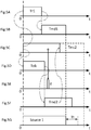
- the Figures 3A to 3G represent switch control timing diagrams in a first case of power transfer in nominal operation, that is to say without fault.
- the figure 3G is a timing diagram illustrating the presence of the first source 1 and its disappearance during a transfer time Tt then the appearance of the second power source 2.
- the sum of the third operating time Tmd1 to disconnect the first source 1, that is to say to open the first switch 4, and the transfer time Tt is less than the second operating time Tmc2 to connect the second source 2, that is to say to close the second switch 5.
- a first time delay Tr1 is applied before the maneuver to disconnect the first source 1, that is to say before a command of the first switch 4.
- Tr 1 tmc 2 - tmd 1 + tt
- the first timer Tr1 must be positive. Therefore it is necessary that: tmc 2 - tmd 1 + tt > 0 and so tmc 2 > tmd 1 + tt
- the second time delay Tr2 must be positive and therefore: tmd 1 + tt > tmc 2
- the transfer time Tt chosen is preferably between 10 milliseconds and 50 milliseconds.
- the “ready to close” contact delivers the closing indicator If ahead of other types of auxiliary contacts, which justifies preferential use.
- the closing indicator If is delivered after a predefined duration following a command to close the second switch.
- an observation window is open, for an observation time Tob, parallel to a command to close the second switch 5, as shown in the 3D figures and 4D .
- the closing indicator If is delivered during the observation period Tob, the closing operation of the second switch can continue.
- the closing indicator If of the second switch 5 is not delivered for the duration Tob of the observation time window, then there is probably a problem of closing the second switch 5 and an opening of the second switch 5 is ordered to not connect the second source 2 following a second scenario.
- the installation and the motors 9 are thus protected from overcurrents and disturbances linked to a transfer duration greater than the predefined transfer duration Tt.
- the second scenario is illustrated by the chronograms represented in Figures 5A to 5G , for which Tmc2> (Tmd1 + Tt).
- the Tob duration observation window is opened simultaneously with the command to close the second switch, as shown in figure 5D .
- the If closing indicator is issued outside the observation window.
- the second switch 5 therefore took longer than expected to execute the closing maneuver, this is an abnormal situation, there is a fault.
- the first scenario is illustrated by the chronograms represented in Figures 4A to 4G , for which Tmc2 ⁇ (Tmd1 + Tt).
- the second time delay Tr2 is started before the maneuver to connect the second source 2 as shown in Figure 4B and 4C , and, in the same way as for the second scenario, the observation window of duration Tob is opened simultaneously with the command to close the second switch, as shown in figure 4D .
- the closing indicator If is issued during the Tob opening time of the observation window, as shown in figure 4D and 4E , the closing operation of the second switch can continue, as shown in figure 4C .
- the chronogram in figure 4G illustrates the disconnection of the first source 1 then the source transfer period followed by the connection of the second source 2.
- the timing diagram in figure 4F illustrates that the cancellation of the connection of the second source 2 was not carried out.
- the process for transferring the power supply of an electrical distribution line 7, from the first source 1 to the second source 2, without overlap, is shown in the form of a flowchart in figure 6 .
- the method includes the step of measuring 100 of the maneuver times Tmc1, Tmc2, Tmd1, Tmd2, to connect and disconnect the first and second sources.
- This measurement step 100 is carried out when the electrical installation is put into service and can be carried out periodically to update the measurements and take into account the wear of the equipment.
- the process continues with two phases initialized simultaneously and taking place in parallel.
- the first phase 200 of connection of the second source 2 begins with a test step 210 if Tmc2 is less than the sum (Tmd1 + Tt). If this is the case, the connection maneuver of the second source 2 is faster than the maneuver disconnection of the first source 1 to which is added the transfer time Tt, then the method goes to step 220 of time delay during the duration Tr2 equal to (Tmd1 + Tt) - Tmc2. If this is not the case, the method continues with step 230 corresponding to the launching of the connection operation of the second source 2 and step 240, executed in parallel with step 230, corresponding to the opening from the observation window. During steps 250 and 260, the method monitors whether the closing indicator If is delivered during the period Tob of opening the observation window.
- the method ends with a step 290 corresponding to a source transfer carried out correctly. If the closing indicator If has not been delivered during the time Tob opening the observation window, the method commands a maneuver to disconnect the second source 2 during a step 270 and the method ends with a step 280 corresponding to a canceled source transfer.
- the second phase 300 of disconnecting the first source 3 from the distribution line 7 begins with a step 310 to test whether Tmc2 is greater than the sum (Tmd1 + Tt). If this is the case, the method goes to step 320 of time delay for the duration Tr1 equal to Tmc2 - (Tmd1 + Tt) then goes to step 330 at the end of the time delay Tr1. If this is not the case, the method continues directly with step 330 corresponding to the launching of the maneuver to disconnect the first source 1.
- the first phase 200 of connection of the second source 2 takes place without passing to step 220 of time delay for the duration Tr2 and the second phase 300 takes place in parallel without passing to l step 320 of time delay during the duration Tr1.
- the process which is the subject of the invention therefore makes it possible to transfer the supply of electrical energy to an electrical distribution line 7, from a first source 1 to a second source 2, during the predefined and controlled transfer time Tt , independent of the time required for the switches to operate. In the event that the transfer time Tt cannot be observed, then the switching of sources is canceled.
- the method described above can be transposed to transfer the supply of electrical energy from the electrical distribution line from the second source to the first source, or alternatively to transfer the supply of electrical energy between two portions of the distribution line. 7, 7b as shown in figure 2 , or any other electrical network configuration.
- a procedure for verifying the opening of the first switch 4 could be carried out during said disconnection maneuver.
- the first source 1 does not disconnect, the source transfer is performed with overlap.
- the first source and the second source being synchronized, the disturbances borne by the loads connected to the supply line will be limited.
- protection must be put in place to limit the mutual influence of the two sources.
- the source inverter 60 can optionally include a man-machine interface 62 intended to supply data for example on the state of the switches, carry out measurements of mean operating time values or allow an operator to initiate the process. source transfer.
- a man-machine interface 62 intended to supply data for example on the state of the switches, carry out measurements of mean operating time values or allow an operator to initiate the process. source transfer.
- a command to activate an actuator by means of an alternating voltage introduces a random delay linked to the phase angle of the alternating voltage at the time of the command.
- Such a delay, included in the maneuver time to connect or disconnect the first or second source would introduce unwanted variability at the first, second, third and fourth maneuver times Tmd1, Tmd2, Tmc1, Tmc2.
- Activation by DC voltage eliminates this variability.
- the first opening actuator 52a of the first switch 4, the second opening actuator 52b of the second switch 5, the first closing actuator 51a of the first switch 4 and the second closing actuator 51b of the second switch 5 are activated by continuous tension.
- the source inverter 60 emits a DC voltage on the fifth link 55a to control the first closing actuator 51a of the first switches 4, the source inverter 60 emits a DC voltage on the sixth link 55b to control the second closing actuator 51b of the second switch 5.
- the source inverter 60 also emits a DC voltage on the third link 56a to control the first opening actuator 52a of the first switch 4, and the source inverter 60 also emits a DC voltage on the fourth link 56b for controlling the second opening actuator 52b of the second switches 5.
- the figure 8 shows such an electric switch in the form of a block diagram illustrating the particular arrangement of the opening 42 and closing 46 mechanisms of the electrical contacts: the actuation of the opening mechanism 42 of the electrical contacts acts on the closing mechanism 46 of the contacts to interrupt a closing movement of said contacts.
- This feature makes it possible to execute the step 270 of maneuvering to disconnect the second source 2, given that the closing indicator If has not been delivered during the time Tob opening the observation window, then that a maneuver for connection to the second source 2 had been engaged previously in step 230.
- the opening mechanism 42 operates on the principle of a first toggle: it comprises a first part 42b movable around a first axis 42a which can move in a first gusset. A first end of said first part 42b carries a first articulation 42c with a second movable part 42d around a second axis 42 e which can move in a second gusset.
- the closing mechanism 46 operates on the principle of a second toggle joint: a third part 46a movable around a third axis 46b carries electrical contacts 41 at one of its ends, the other end carrying a second articulation 46c with the first Exhibit 42b.
- the first closing actuator 51a acts on the third part at the level of the second articulation 46c in the direction indicated by the arrow to obtain the closure of the electrical contacts 41.
- the first opening actuator 52a acts on the first movable part and the second moving part at the level of the first articulation 42c. Activation of the first opening actuator 52a causes the third part 46a to rotate in the direction of opening of the contacts 41.
- a spring 43 keeps the first and the second toggle joint in a stable position in the absence of an opening command or closing contacts. The clever arrangement of the first and of the second toggle joint thus makes it possible to cancel a maneuver for closing the contacts 41 when a maneuver for disconnecting the second source 2 is ordered during a step 270.
- the opening mechanism 42 and the closing mechanism 46 described above are preferred embodiments, however other mechanical principles allowing cancellation of closing of the contacts 41 by an opening command can be used.
- the energy transfer method and the source inverter which is the subject of the invention can be used on networks comprising single-phase or three-phase sources, without limitation linked to the frequency of the sources nor to the power of the loads to be supplied. .
- the energy transfer method and the source inverter which are the subject of the invention are more particularly suitable for transferring the supply of electrical energy to an electrical distribution line to which motors, a first source to a second source, without overlapping from one source to the other and guaranteeing a short and controlled transfer time.
- Conventional switches such as power circuit breakers can be used, without requiring special properties of speed of operation. Under these conditions, the source reverser is produced with standard, economically advantageous products, for which the availability of maintenance parts is guaranteed.
Applications Claiming Priority (1)
| Application Number | Priority Date | Filing Date | Title |
|---|---|---|---|
| FR1857401A FR3084973B1 (fr) | 2018-08-09 | 2018-08-09 | Procede de transfert sans recouvrement de sources d'energie electrique et inverseur de source mettant en oeuvre un tel procede |
Publications (2)
| Publication Number | Publication Date |
|---|---|
| EP3609034A1 true EP3609034A1 (de) | 2020-02-12 |
| EP3609034B1 EP3609034B1 (de) | 2021-02-17 |
Family
ID=65201053
Family Applications (1)
| Application Number | Title | Priority Date | Filing Date |
|---|---|---|---|
| EP19180775.9A Active EP3609034B1 (de) | 2018-08-09 | 2019-06-18 | Verfahren zum überlappungsfreien umschalten von elektrischen energiequellen und quellenumschalter, der dieses verfahren anwendet |
Country Status (5)
| Country | Link |
|---|---|
| US (1) | US11063468B2 (de) |
| EP (1) | EP3609034B1 (de) |
| CN (1) | CN110829573B (de) |
| ES (1) | ES2868275T3 (de) |
| FR (1) | FR3084973B1 (de) |
Citations (8)
| Publication number | Priority date | Publication date | Assignee | Title |
|---|---|---|---|---|
| EP0471178A2 (de) * | 1990-08-14 | 1992-02-19 | International Business Machines Corporation | Energieübertragungseinheit |
| EP1014534A1 (de) | 1998-12-22 | 2000-06-28 | S & C ELECTRIC COMPANY | Quellenumschaltsystem und -verfahren |
| US20140001860A1 (en) | 2011-02-28 | 2014-01-02 | Zhen Cao | Fast bus transfer method and device |
| CN103683469B (zh) * | 2012-09-26 | 2016-04-06 | 力博特公司 | 一种不间断电源输入切换的控制方法及设备 |
| US20160233720A1 (en) * | 2013-12-31 | 2016-08-11 | Lite-On, Inc. | Dual input power supply system and method |
| US9570253B1 (en) * | 2011-11-28 | 2017-02-14 | Amazon Technologies, Inc. | System and method with timing self-configuration |
| US20170090549A1 (en) * | 2015-09-25 | 2017-03-30 | Hon Hai Precision Industry Co., Ltd. | Switch control device and method for power |
| US20170366040A1 (en) * | 2016-06-16 | 2017-12-21 | Eaton Corporation | Transfer switch apparatus and methods using transition time monitoring and adaptation |
Family Cites Families (7)
| Publication number | Priority date | Publication date | Assignee | Title |
|---|---|---|---|---|
| US6051893A (en) * | 1998-10-29 | 2000-04-18 | Mitsubishi Denki Kabushiki Kaisha | Electric power supply system for load |
| CN1599189A (zh) * | 2003-09-18 | 2005-03-23 | 帕尔威电力器具公司 | 具有两个继电器旁路电路的在线式不间断电源及其操作方法 |
| US7535129B2 (en) * | 2006-05-17 | 2009-05-19 | Twinsource, Llc | Method and apparatus for transfer of a critical load from one source to a back up source using magnetically latched relays |
| CN105556798B (zh) * | 2013-02-26 | 2019-05-28 | 佐尼特结构解决方案有限责任公司 | 并行冗余电力分配 |
| US9419473B2 (en) * | 2013-12-19 | 2016-08-16 | Eaton Corporation | Automatic transfer switch (ATS) bypass switch |
| CN106464003B (zh) * | 2014-04-04 | 2020-09-15 | 施耐德电气It公司 | 用于快速功率输送模式改变的系统和方法 |
| US10523049B2 (en) * | 2014-12-25 | 2019-12-31 | Toshiba Mitsubishi-Electric Industrial Systems Corporation | Uninterruptible power supply apparatus |
-
2018
- 2018-08-09 FR FR1857401A patent/FR3084973B1/fr not_active Expired - Fee Related
-
2019
- 2019-06-18 EP EP19180775.9A patent/EP3609034B1/de active Active
- 2019-06-18 ES ES19180775T patent/ES2868275T3/es active Active
- 2019-06-28 US US16/456,088 patent/US11063468B2/en active Active
- 2019-08-01 CN CN201910706171.9A patent/CN110829573B/zh active Active
Patent Citations (8)
| Publication number | Priority date | Publication date | Assignee | Title |
|---|---|---|---|---|
| EP0471178A2 (de) * | 1990-08-14 | 1992-02-19 | International Business Machines Corporation | Energieübertragungseinheit |
| EP1014534A1 (de) | 1998-12-22 | 2000-06-28 | S & C ELECTRIC COMPANY | Quellenumschaltsystem und -verfahren |
| US20140001860A1 (en) | 2011-02-28 | 2014-01-02 | Zhen Cao | Fast bus transfer method and device |
| US9570253B1 (en) * | 2011-11-28 | 2017-02-14 | Amazon Technologies, Inc. | System and method with timing self-configuration |
| CN103683469B (zh) * | 2012-09-26 | 2016-04-06 | 力博特公司 | 一种不间断电源输入切换的控制方法及设备 |
| US20160233720A1 (en) * | 2013-12-31 | 2016-08-11 | Lite-On, Inc. | Dual input power supply system and method |
| US20170090549A1 (en) * | 2015-09-25 | 2017-03-30 | Hon Hai Precision Industry Co., Ltd. | Switch control device and method for power |
| US20170366040A1 (en) * | 2016-06-16 | 2017-12-21 | Eaton Corporation | Transfer switch apparatus and methods using transition time monitoring and adaptation |
Also Published As
| Publication number | Publication date |
|---|---|
| ES2868275T3 (es) | 2021-10-21 |
| RU2019124876A (ru) | 2021-02-08 |
| US11063468B2 (en) | 2021-07-13 |
| CN110829573A (zh) | 2020-02-21 |
| FR3084973A1 (fr) | 2020-02-14 |
| FR3084973B1 (fr) | 2021-11-05 |
| CN110829573B (zh) | 2023-11-28 |
| US20200052525A1 (en) | 2020-02-13 |
| EP3609034B1 (de) | 2021-02-17 |
Similar Documents
| Publication | Publication Date | Title |
|---|---|---|
| EP2320535B1 (de) | Elektrischer Schutzschalter, Stromverteilungsvorrichtung, die mit einem solchen Schutzschalter ausgestattet ist, und Begrenzungsverfahren des Stromflusses | |
| EP2849196B1 (de) | Verfahren zur Erkennung der Ursache eines Spannungsverlusts vor einem Trennschalter, Hilfsgerät für Trennschalter sowie elektrisches System, das einen solchen Trennschalter und ein solches Hilfsgerät umfasst | |
| EP3577672B1 (de) | Hochspannungsgleichstromunterbrechungsvorrichtung | |
| EP1225673B1 (de) | Elektrische Energieverteilungsvorrichtung, Anlage mit einer solchen Vorrichtung und Verfahren zum elektrischen Schutz | |
| EP3248257A1 (de) | Vorrichtung zur steuerung einer elektrischen permanentmagnet-synchronmaschine | |
| EP3276769A1 (de) | Gerät zur überwachung/steuerung eines schalters für quellen | |
| EP3513478A1 (de) | Schutz für ein hvdc-netzwerk | |
| EP3609034B1 (de) | Verfahren zum überlappungsfreien umschalten von elektrischen energiequellen und quellenumschalter, der dieses verfahren anwendet | |
| WO2017103355A1 (fr) | Procede de controle d'un appareil de coupure electrique et installation electrique comprenant un appareil de coupure electrique | |
| EP2783440B1 (de) | Vorrichtung und verfahren zum schutz vor einem lichtbogen | |
| EP3275064B1 (de) | Verfahren und vorrichtung zum schutz eines stromnetzes | |
| EP3694068B1 (de) | Statisches schaltsystem und system zur begrenzung eines gleichstroms | |
| FR2976414A1 (fr) | Procede de protection differentielle d'une liaison electrique de grande longueur avec courant capacitif eleve dans un reseau moyenne, haute ou tres haute tension | |
| RU2795409C2 (ru) | Способ для свободного от наложения переключения источников электрической мощности и переключатель источников, реализующий такой способ | |
| EP3964901A1 (de) | Steuerschnittstelle für mittelspannungsschutz- und trennschalter | |
| EP3389076A1 (de) | Steuerverfahren und -vorrichtung eines stellglieds, und elektrisches schutzgerät, das eine solche vorrichtung umfasst | |
| CA3004694A1 (fr) | Procede et dispositif de mise sous tension d'un transformateur de puissance | |
| EP3273258B1 (de) | Verfahren zur steuerung einer elektrischen anlage von einem entfernten ort aus | |
| FR2706094A1 (fr) | Dispositif de commande d'un mécanisme entrainé par ua moins un moteur électrique. | |
| BE898689A (fr) | Procede et appareil de blocage automatique d'un interrupteur de deconnexion de charge a proximite d'un defaut localise | |
| WO2005001868A1 (fr) | Appareil electrique interrupteur a plusieurs actionneurs. | |
| FR3099289A1 (fr) | Contacteur et procédé de commande d’un contacteur | |
| FR2989236A1 (fr) | Procede de mesure pour la detection d'un defaut d'une zone triphasee | |
| FR2511204A1 (fr) | Dispositif de protection differentielle contre les courts-circuits entre les phases d'un moteur electrique | |
| BE463115A (de) |
Legal Events
| Date | Code | Title | Description |
|---|---|---|---|
| PUAI | Public reference made under article 153(3) epc to a published international application that has entered the european phase |
Free format text: ORIGINAL CODE: 0009012 |
|
| STAA | Information on the status of an ep patent application or granted ep patent |
Free format text: STATUS: THE APPLICATION HAS BEEN PUBLISHED |
|
| AK | Designated contracting states |
Kind code of ref document: A1 Designated state(s): AL AT BE BG CH CY CZ DE DK EE ES FI FR GB GR HR HU IE IS IT LI LT LU LV MC MK MT NL NO PL PT RO RS SE SI SK SM TR |
|
| AX | Request for extension of the european patent |
Extension state: BA ME |
|
| STAA | Information on the status of an ep patent application or granted ep patent |
Free format text: STATUS: REQUEST FOR EXAMINATION WAS MADE |
|
| 17P | Request for examination filed |
Effective date: 20200224 |
|
| RBV | Designated contracting states (corrected) |
Designated state(s): AL AT BE BG CH CY CZ DE DK EE ES FI FR GB GR HR HU IE IS IT LI LT LU LV MC MK MT NL NO PL PT RO RS SE SI SK SM TR |
|
| GRAP | Despatch of communication of intention to grant a patent |
Free format text: ORIGINAL CODE: EPIDOSNIGR1 |
|
| STAA | Information on the status of an ep patent application or granted ep patent |
Free format text: STATUS: GRANT OF PATENT IS INTENDED |
|
| RIC1 | Information provided on ipc code assigned before grant |
Ipc: H01H 50/86 20060101ALN20201007BHEP Ipc: H01H 47/18 20060101ALN20201007BHEP Ipc: H02J 3/00 20060101AFI20201007BHEP Ipc: H01H 7/16 20060101ALI20201007BHEP Ipc: H01H 9/56 20060101ALI20201007BHEP Ipc: H02J 9/06 20060101ALI20201007BHEP |
|
| INTG | Intention to grant announced |
Effective date: 20201103 |
|
| GRAS | Grant fee paid |
Free format text: ORIGINAL CODE: EPIDOSNIGR3 |
|
| GRAA | (expected) grant |
Free format text: ORIGINAL CODE: 0009210 |
|
| STAA | Information on the status of an ep patent application or granted ep patent |
Free format text: STATUS: THE PATENT HAS BEEN GRANTED |
|
| AK | Designated contracting states |
Kind code of ref document: B1 Designated state(s): AL AT BE BG CH CY CZ DE DK EE ES FI FR GB GR HR HU IE IS IT LI LT LU LV MC MK MT NL NO PL PT RO RS SE SI SK SM TR |
|
| REG | Reference to a national code |
Ref country code: GB Ref legal event code: FG4D Free format text: NOT ENGLISH |
|
| REG | Reference to a national code |
Ref country code: CH Ref legal event code: EP |
|
| REG | Reference to a national code |
Ref country code: DE Ref legal event code: R096 Ref document number: 602019002550 Country of ref document: DE |
|
| REG | Reference to a national code |
Ref country code: AT Ref legal event code: REF Ref document number: 1362741 Country of ref document: AT Kind code of ref document: T Effective date: 20210315 |
|
| REG | Reference to a national code |
Ref country code: IE Ref legal event code: FG4D Free format text: LANGUAGE OF EP DOCUMENT: FRENCH |
|
| REG | Reference to a national code |
Ref country code: NL Ref legal event code: FP |
|
| REG | Reference to a national code |
Ref country code: NO Ref legal event code: T2 Effective date: 20210217 Ref country code: LT Ref legal event code: MG9D |
|
| PG25 | Lapsed in a contracting state [announced via postgrant information from national office to epo] |
Ref country code: BG Free format text: LAPSE BECAUSE OF FAILURE TO SUBMIT A TRANSLATION OF THE DESCRIPTION OR TO PAY THE FEE WITHIN THE PRESCRIBED TIME-LIMIT Effective date: 20210517 Ref country code: HR Free format text: LAPSE BECAUSE OF FAILURE TO SUBMIT A TRANSLATION OF THE DESCRIPTION OR TO PAY THE FEE WITHIN THE PRESCRIBED TIME-LIMIT Effective date: 20210217 Ref country code: FI Free format text: LAPSE BECAUSE OF FAILURE TO SUBMIT A TRANSLATION OF THE DESCRIPTION OR TO PAY THE FEE WITHIN THE PRESCRIBED TIME-LIMIT Effective date: 20210217 Ref country code: GR Free format text: LAPSE BECAUSE OF FAILURE TO SUBMIT A TRANSLATION OF THE DESCRIPTION OR TO PAY THE FEE WITHIN THE PRESCRIBED TIME-LIMIT Effective date: 20210518 Ref country code: PT Free format text: LAPSE BECAUSE OF FAILURE TO SUBMIT A TRANSLATION OF THE DESCRIPTION OR TO PAY THE FEE WITHIN THE PRESCRIBED TIME-LIMIT Effective date: 20210617 Ref country code: LT Free format text: LAPSE BECAUSE OF FAILURE TO SUBMIT A TRANSLATION OF THE DESCRIPTION OR TO PAY THE FEE WITHIN THE PRESCRIBED TIME-LIMIT Effective date: 20210217 |
|
| REG | Reference to a national code |
Ref country code: AT Ref legal event code: MK05 Ref document number: 1362741 Country of ref document: AT Kind code of ref document: T Effective date: 20210217 |
|
| PG25 | Lapsed in a contracting state [announced via postgrant information from national office to epo] |
Ref country code: PL Free format text: LAPSE BECAUSE OF FAILURE TO SUBMIT A TRANSLATION OF THE DESCRIPTION OR TO PAY THE FEE WITHIN THE PRESCRIBED TIME-LIMIT Effective date: 20210217 Ref country code: LV Free format text: LAPSE BECAUSE OF FAILURE TO SUBMIT A TRANSLATION OF THE DESCRIPTION OR TO PAY THE FEE WITHIN THE PRESCRIBED TIME-LIMIT Effective date: 20210217 Ref country code: SE Free format text: LAPSE BECAUSE OF FAILURE TO SUBMIT A TRANSLATION OF THE DESCRIPTION OR TO PAY THE FEE WITHIN THE PRESCRIBED TIME-LIMIT Effective date: 20210217 Ref country code: RS Free format text: LAPSE BECAUSE OF FAILURE TO SUBMIT A TRANSLATION OF THE DESCRIPTION OR TO PAY THE FEE WITHIN THE PRESCRIBED TIME-LIMIT Effective date: 20210217 |
|
| PG25 | Lapsed in a contracting state [announced via postgrant information from national office to epo] |
Ref country code: IS Free format text: LAPSE BECAUSE OF FAILURE TO SUBMIT A TRANSLATION OF THE DESCRIPTION OR TO PAY THE FEE WITHIN THE PRESCRIBED TIME-LIMIT Effective date: 20210617 |
|
| REG | Reference to a national code |
Ref country code: ES Ref legal event code: FG2A Ref document number: 2868275 Country of ref document: ES Kind code of ref document: T3 Effective date: 20211021 |
|
| PG25 | Lapsed in a contracting state [announced via postgrant information from national office to epo] |
Ref country code: EE Free format text: LAPSE BECAUSE OF FAILURE TO SUBMIT A TRANSLATION OF THE DESCRIPTION OR TO PAY THE FEE WITHIN THE PRESCRIBED TIME-LIMIT Effective date: 20210217 Ref country code: CZ Free format text: LAPSE BECAUSE OF FAILURE TO SUBMIT A TRANSLATION OF THE DESCRIPTION OR TO PAY THE FEE WITHIN THE PRESCRIBED TIME-LIMIT Effective date: 20210217 Ref country code: AT Free format text: LAPSE BECAUSE OF FAILURE TO SUBMIT A TRANSLATION OF THE DESCRIPTION OR TO PAY THE FEE WITHIN THE PRESCRIBED TIME-LIMIT Effective date: 20210217 Ref country code: SM Free format text: LAPSE BECAUSE OF FAILURE TO SUBMIT A TRANSLATION OF THE DESCRIPTION OR TO PAY THE FEE WITHIN THE PRESCRIBED TIME-LIMIT Effective date: 20210217 |
|
| REG | Reference to a national code |
Ref country code: DE Ref legal event code: R097 Ref document number: 602019002550 Country of ref document: DE |
|
| PG25 | Lapsed in a contracting state [announced via postgrant information from national office to epo] |
Ref country code: RO Free format text: LAPSE BECAUSE OF FAILURE TO SUBMIT A TRANSLATION OF THE DESCRIPTION OR TO PAY THE FEE WITHIN THE PRESCRIBED TIME-LIMIT Effective date: 20210217 Ref country code: SK Free format text: LAPSE BECAUSE OF FAILURE TO SUBMIT A TRANSLATION OF THE DESCRIPTION OR TO PAY THE FEE WITHIN THE PRESCRIBED TIME-LIMIT Effective date: 20210217 Ref country code: DK Free format text: LAPSE BECAUSE OF FAILURE TO SUBMIT A TRANSLATION OF THE DESCRIPTION OR TO PAY THE FEE WITHIN THE PRESCRIBED TIME-LIMIT Effective date: 20210217 |
|
| PLBE | No opposition filed within time limit |
Free format text: ORIGINAL CODE: 0009261 |
|
| STAA | Information on the status of an ep patent application or granted ep patent |
Free format text: STATUS: NO OPPOSITION FILED WITHIN TIME LIMIT |
|
| 26N | No opposition filed |
Effective date: 20211118 |
|
| PG25 | Lapsed in a contracting state [announced via postgrant information from national office to epo] |
Ref country code: MC Free format text: LAPSE BECAUSE OF FAILURE TO SUBMIT A TRANSLATION OF THE DESCRIPTION OR TO PAY THE FEE WITHIN THE PRESCRIBED TIME-LIMIT Effective date: 20210217 Ref country code: AL Free format text: LAPSE BECAUSE OF FAILURE TO SUBMIT A TRANSLATION OF THE DESCRIPTION OR TO PAY THE FEE WITHIN THE PRESCRIBED TIME-LIMIT Effective date: 20210217 |
|
| PG25 | Lapsed in a contracting state [announced via postgrant information from national office to epo] |
Ref country code: SI Free format text: LAPSE BECAUSE OF FAILURE TO SUBMIT A TRANSLATION OF THE DESCRIPTION OR TO PAY THE FEE WITHIN THE PRESCRIBED TIME-LIMIT Effective date: 20210217 |
|
| REG | Reference to a national code |
Ref country code: BE Ref legal event code: MM Effective date: 20210630 |
|
| PG25 | Lapsed in a contracting state [announced via postgrant information from national office to epo] |
Ref country code: LU Free format text: LAPSE BECAUSE OF NON-PAYMENT OF DUE FEES Effective date: 20210618 |
|
| PG25 | Lapsed in a contracting state [announced via postgrant information from national office to epo] |
Ref country code: IE Free format text: LAPSE BECAUSE OF NON-PAYMENT OF DUE FEES Effective date: 20210618 |
|
| PG25 | Lapsed in a contracting state [announced via postgrant information from national office to epo] |
Ref country code: IS Free format text: LAPSE BECAUSE OF FAILURE TO SUBMIT A TRANSLATION OF THE DESCRIPTION OR TO PAY THE FEE WITHIN THE PRESCRIBED TIME-LIMIT Effective date: 20210617 |
|
| PG25 | Lapsed in a contracting state [announced via postgrant information from national office to epo] |
Ref country code: BE Free format text: LAPSE BECAUSE OF NON-PAYMENT OF DUE FEES Effective date: 20210630 |
|
| REG | Reference to a national code |
Ref country code: CH Ref legal event code: PL |
|
| PG25 | Lapsed in a contracting state [announced via postgrant information from national office to epo] |
Ref country code: LI Free format text: LAPSE BECAUSE OF NON-PAYMENT OF DUE FEES Effective date: 20220630 Ref country code: CH Free format text: LAPSE BECAUSE OF NON-PAYMENT OF DUE FEES Effective date: 20220630 |
|
| PG25 | Lapsed in a contracting state [announced via postgrant information from national office to epo] |
Ref country code: CY Free format text: LAPSE BECAUSE OF FAILURE TO SUBMIT A TRANSLATION OF THE DESCRIPTION OR TO PAY THE FEE WITHIN THE PRESCRIBED TIME-LIMIT Effective date: 20210217 |
|
| PG25 | Lapsed in a contracting state [announced via postgrant information from national office to epo] |
Ref country code: HU Free format text: LAPSE BECAUSE OF FAILURE TO SUBMIT A TRANSLATION OF THE DESCRIPTION OR TO PAY THE FEE WITHIN THE PRESCRIBED TIME-LIMIT; INVALID AB INITIO Effective date: 20190618 |
|
| PGFP | Annual fee paid to national office [announced via postgrant information from national office to epo] |
Ref country code: NO Payment date: 20230620 Year of fee payment: 5 Ref country code: NL Payment date: 20230626 Year of fee payment: 5 Ref country code: FR Payment date: 20230622 Year of fee payment: 5 Ref country code: DE Payment date: 20230627 Year of fee payment: 5 |
|
| PGFP | Annual fee paid to national office [announced via postgrant information from national office to epo] |
Ref country code: IT Payment date: 20230620 Year of fee payment: 5 Ref country code: GB Payment date: 20230620 Year of fee payment: 5 Ref country code: ES Payment date: 20230721 Year of fee payment: 5 |
|
| PG25 | Lapsed in a contracting state [announced via postgrant information from national office to epo] |
Ref country code: MK Free format text: LAPSE BECAUSE OF FAILURE TO SUBMIT A TRANSLATION OF THE DESCRIPTION OR TO PAY THE FEE WITHIN THE PRESCRIBED TIME-LIMIT Effective date: 20210217 |