EP3609034A1 - Method for transferring electrical energy sources without recovery and source inverter implementing such a method - Google Patents
Method for transferring electrical energy sources without recovery and source inverter implementing such a method Download PDFInfo
- Publication number
- EP3609034A1 EP3609034A1 EP19180775.9A EP19180775A EP3609034A1 EP 3609034 A1 EP3609034 A1 EP 3609034A1 EP 19180775 A EP19180775 A EP 19180775A EP 3609034 A1 EP3609034 A1 EP 3609034A1
- Authority
- EP
- European Patent Office
- Prior art keywords
- source
- switch
- closing
- time
- opening
- Prior art date
- Legal status (The legal status is an assumption and is not a legal conclusion. Google has not performed a legal analysis and makes no representation as to the accuracy of the status listed.)
- Granted
Links
- 238000000034 method Methods 0.000 title claims abstract description 53
- 238000011084 recovery Methods 0.000 title description 2
- 238000012546 transfer Methods 0.000 claims abstract description 71
- 101100207042 Caenorhabditis elegans unc-94 gene Proteins 0.000 claims description 30
- 101100207005 Caenorhabditis elegans tmc-2 gene Proteins 0.000 claims description 29
- 230000007246 mechanism Effects 0.000 claims description 19
- 238000011144 upstream manufacturing Methods 0.000 claims description 9
- 101100425646 Caenorhabditis elegans tmc-1 gene Proteins 0.000 claims description 4
- 238000012545 processing Methods 0.000 claims description 3
- 238000010586 diagram Methods 0.000 description 12
- 238000010616 electrical installation Methods 0.000 description 8
- 238000005259 measurement Methods 0.000 description 7
- 230000008569 process Effects 0.000 description 5
- 238000009434 installation Methods 0.000 description 4
- 230000004913 activation Effects 0.000 description 2
- 230000008034 disappearance Effects 0.000 description 2
- 238000004519 manufacturing process Methods 0.000 description 2
- 230000001360 synchronised effect Effects 0.000 description 2
- 238000012360 testing method Methods 0.000 description 2
- -1 Tmd2 Proteins 0.000 description 1
- 230000002159 abnormal effect Effects 0.000 description 1
- 230000002238 attenuated effect Effects 0.000 description 1
- 230000007423 decrease Effects 0.000 description 1
- 230000003111 delayed effect Effects 0.000 description 1
- 230000000694 effects Effects 0.000 description 1
- 235000021183 entrée Nutrition 0.000 description 1
- 230000002349 favourable effect Effects 0.000 description 1
- 230000003993 interaction Effects 0.000 description 1
- 238000012423 maintenance Methods 0.000 description 1
- SYHGEUNFJIGTRX-UHFFFAOYSA-N methylenedioxypyrovalerone Chemical compound C=1C=C2OCOC2=CC=1C(=O)C(CCC)N1CCCC1 SYHGEUNFJIGTRX-UHFFFAOYSA-N 0.000 description 1
- 238000013021 overheating Methods 0.000 description 1
- 238000012163 sequencing technique Methods 0.000 description 1
- 230000007704 transition Effects 0.000 description 1
- 230000002747 voluntary effect Effects 0.000 description 1
Images


Classifications
-
- H—ELECTRICITY
- H02—GENERATION; CONVERSION OR DISTRIBUTION OF ELECTRIC POWER
- H02J—CIRCUIT ARRANGEMENTS OR SYSTEMS FOR SUPPLYING OR DISTRIBUTING ELECTRIC POWER; SYSTEMS FOR STORING ELECTRIC ENERGY
- H02J9/00—Circuit arrangements for emergency or stand-by power supply, e.g. for emergency lighting
- H02J9/04—Circuit arrangements for emergency or stand-by power supply, e.g. for emergency lighting in which the distribution system is disconnected from the normal source and connected to a standby source
- H02J9/06—Circuit arrangements for emergency or stand-by power supply, e.g. for emergency lighting in which the distribution system is disconnected from the normal source and connected to a standby source with automatic change-over, e.g. UPS systems
- H02J9/061—Circuit arrangements for emergency or stand-by power supply, e.g. for emergency lighting in which the distribution system is disconnected from the normal source and connected to a standby source with automatic change-over, e.g. UPS systems for DC powered loads
-
- H—ELECTRICITY
- H02—GENERATION; CONVERSION OR DISTRIBUTION OF ELECTRIC POWER
- H02J—CIRCUIT ARRANGEMENTS OR SYSTEMS FOR SUPPLYING OR DISTRIBUTING ELECTRIC POWER; SYSTEMS FOR STORING ELECTRIC ENERGY
- H02J9/00—Circuit arrangements for emergency or stand-by power supply, e.g. for emergency lighting
- H02J9/04—Circuit arrangements for emergency or stand-by power supply, e.g. for emergency lighting in which the distribution system is disconnected from the normal source and connected to a standby source
- H02J9/06—Circuit arrangements for emergency or stand-by power supply, e.g. for emergency lighting in which the distribution system is disconnected from the normal source and connected to a standby source with automatic change-over, e.g. UPS systems
- H02J9/062—Circuit arrangements for emergency or stand-by power supply, e.g. for emergency lighting in which the distribution system is disconnected from the normal source and connected to a standby source with automatic change-over, e.g. UPS systems for AC powered loads
-
- H—ELECTRICITY
- H02—GENERATION; CONVERSION OR DISTRIBUTION OF ELECTRIC POWER
- H02J—CIRCUIT ARRANGEMENTS OR SYSTEMS FOR SUPPLYING OR DISTRIBUTING ELECTRIC POWER; SYSTEMS FOR STORING ELECTRIC ENERGY
- H02J3/00—Circuit arrangements for ac mains or ac distribution networks
- H02J3/007—Arrangements for selectively connecting the load or loads to one or several among a plurality of power lines or power sources
-
- H—ELECTRICITY
- H02—GENERATION; CONVERSION OR DISTRIBUTION OF ELECTRIC POWER
- H02J—CIRCUIT ARRANGEMENTS OR SYSTEMS FOR SUPPLYING OR DISTRIBUTING ELECTRIC POWER; SYSTEMS FOR STORING ELECTRIC ENERGY
- H02J3/00—Circuit arrangements for ac mains or ac distribution networks
- H02J3/38—Arrangements for parallely feeding a single network by two or more generators, converters or transformers
-
- H—ELECTRICITY
- H01—ELECTRIC ELEMENTS
- H01H—ELECTRIC SWITCHES; RELAYS; SELECTORS; EMERGENCY PROTECTIVE DEVICES
- H01H9/00—Details of switching devices, not covered by groups H01H1/00 - H01H7/00
- H01H9/54—Circuit arrangements not adapted to a particular application of the switching device and for which no provision exists elsewhere
- H01H9/56—Circuit arrangements not adapted to a particular application of the switching device and for which no provision exists elsewhere for ensuring operation of the switch at a predetermined point in the ac cycle
- H01H2009/566—Circuit arrangements not adapted to a particular application of the switching device and for which no provision exists elsewhere for ensuring operation of the switch at a predetermined point in the ac cycle with self learning, e.g. measured delay is used in later actuations
-
- H—ELECTRICITY
- H01—ELECTRIC ELEMENTS
- H01H—ELECTRIC SWITCHES; RELAYS; SELECTORS; EMERGENCY PROTECTIVE DEVICES
- H01H2300/00—Orthogonal indexing scheme relating to electric switches, relays, selectors or emergency protective devices covered by H01H
- H01H2300/018—Application transfer; between utility and emergency power supply
-
- H—ELECTRICITY
- H01—ELECTRIC ELEMENTS
- H01H—ELECTRIC SWITCHES; RELAYS; SELECTORS; EMERGENCY PROTECTIVE DEVICES
- H01H7/00—Devices for introducing a predetermined time delay between the initiation of the switching operation and the opening or closing of the contacts
- H01H7/16—Devices for ensuring operation of the switch at a predetermined point in the ac cycle
-
- H—ELECTRICITY
- H01—ELECTRIC ELEMENTS
- H01H—ELECTRIC SWITCHES; RELAYS; SELECTORS; EMERGENCY PROTECTIVE DEVICES
- H01H9/00—Details of switching devices, not covered by groups H01H1/00 - H01H7/00
- H01H9/54—Circuit arrangements not adapted to a particular application of the switching device and for which no provision exists elsewhere
- H01H9/56—Circuit arrangements not adapted to a particular application of the switching device and for which no provision exists elsewhere for ensuring operation of the switch at a predetermined point in the ac cycle
-
- H—ELECTRICITY
- H02—GENERATION; CONVERSION OR DISTRIBUTION OF ELECTRIC POWER
- H02J—CIRCUIT ARRANGEMENTS OR SYSTEMS FOR SUPPLYING OR DISTRIBUTING ELECTRIC POWER; SYSTEMS FOR STORING ELECTRIC ENERGY
- H02J9/00—Circuit arrangements for emergency or stand-by power supply, e.g. for emergency lighting
- H02J9/04—Circuit arrangements for emergency or stand-by power supply, e.g. for emergency lighting in which the distribution system is disconnected from the normal source and connected to a standby source
- H02J9/06—Circuit arrangements for emergency or stand-by power supply, e.g. for emergency lighting in which the distribution system is disconnected from the normal source and connected to a standby source with automatic change-over, e.g. UPS systems
- H02J9/068—Electronic means for switching from one power supply to another power supply, e.g. to avoid parallel connection
Definitions
- the invention relates to a method for transferring the power supply of an electrical distribution line from a first source to a second source.
- the invention also relates to a source inverter intended to control at least a first switch and a second switch for connecting, without overlap, sources of electrical energy to an energy distribution line.
- a device generally called a "source inverter” is used: as soon as a first source of energy presents a risk of disappearance, for example due to overheating of a MV / LV transformer, the source inverter switches the arrival of electrical energy to a second energy source.
- This second source is an output of a redundant transformer of the electrical installation, or an emergency power line, or even an autonomous generator.
- the transfer of the electric power supply source from a first source to a second source requires that the first source and the second source be synchronized, that is to say that the amplitude and the phase of the first source and of the second source must be identical, or between certain limits, at the time of switching.
- significant disturbances can appear when motors are connected to the supply line.
- the mechanical inertia of the motor and its load as well as the magnetic remanence of the rotor bring the motor into a generator operating mode which tends to compensate for the faulty source.
- the rotational speed of the motor decreases more or less rapidly depending on the resistive torque which opposes the inertia of the motor and load assembly.
- the frequency and phase of the voltage supplied by the motor deviate from the frequency and phase of the network.
- a re-supply by an energy source having a different frequency and / or phase causes overvoltages, overcurrents and mechanical jolts which can affect the motor or the electrical installation.
- the effects are further amplified when several motors are powered by the same energy source. It is therefore essential to carry out the source transfer as quickly as possible, preferably for a predefined transfer duration, long enough for the transients linked to a disconnection from a source to be able to cancel or to be greatly attenuated, and short enough so that the engine (s) do not have time to slow down too much.
- a transfer time of a few tens of milliseconds is optimal for industrial power equipment including motors.
- the document US 2014/001 860 A1 describes a source transfer method comprising a measurement of the electrical parameters, then a calculation of the voltage and phase differences between the voltage of the emergency source and the voltage generated by the motor
- This method requires measurements of electrical parameters, voltage, phases, and controls a transfer for a phase difference of up to 90 °.
- Such a phase difference can be the source of significant disturbances in the operation of high power motors.
- the document EP 1 014 534 A1 describes a source inverter capable of transferring the sources in a minimum time and for this implements fast switches.
- the system does not take into account the opening and closing times of the switches which can lead to a "closed" transition, that is to say that the main faulty source and the backup source are temporarily connected to each other for the time necessary to switch the sources, which can cause overcurrents in certain parts of the electrical circuit.
- the cost of a fast switch is much higher than the cost of a standard switch and the duration of source transfer, although low, cannot be limited to only a few tens of milliseconds.
- the subject of the invention is a method and a source reversing device for loads such as high power motors making it possible to guarantee rapid switching from a faulty source to a backup source, or vice versa when the faulty source has recovered its nominal properties.
- the first time delay is applied before the command to open the first switch when the second operating time to connect the second source is greater than the sum of the third operating time to disconnect the first source and the transfer time.
- the first time delay is equal to the second operating time to connect the second source minus the sum of the third operating time to disconnect the first source and the transfer time.
- the second time delay is applied before the command to close the second switch when the second operating time to connect the second source is less than the sum of the third operating time to disconnect the first source and the transfer time.
- the second time delay is equal to the sum of the third operating time to disconnect the first source and the transfer time minus the second operating time to connect the second source.
- the transfer time is between 10 ms and 50 ms.
- an observation window with a predefined observation duration is opened simultaneously with the command to close the second switch.
- an opening of the second switch is commanded when an indicator for closing the second switch is not issued during the observation period.
- the closing indicator of the second switch is delivered during an execution of a closing movement of the contacts of said second switch.
- the closing indicator of the second switch is delivered when the contacts of said second switch are closed.
- the closing indicator of the second switch is delivered when the contacts of said second switch are no longer open.
- the first and second closing actuators of the first and second switches are activated by a DC voltage and the source inverter emits a DC voltage on the fifth and sixth connections to respectively control the first and second closing actuators of the first and of the second switch.
- the first and second opening actuators of the first and second switches are activated by a DC voltage and the source inverter emits a DC voltage on the third and fourth links to respectively control the first and second opening actuators of the first and second switch.
- the figure 1 is a classic schematic representation of an electrical installation comprising a source inverter.
- a first source 1 supplies electrical energy to one or more loads 8, 9.
- the first source can be, for example, an electrical energy distribution network or an output of a MV / LV transformer.
- a first type of load 8 is composed of an item of equipment or a set of several electrical items of equipment.
- a second type of load 9 is made up of motors.
- a first switch 4 connected upstream to the first source 1 and downstream to a distribution line 7, for example a busbar, is controlled to close or open in order to connect or disconnect the first source 1 to the distribution line 7.
- the loads 8, 9 are connected to the distribution line 7.
- the first switch 4 is preferably a circuit breaker but can also be a contactor or a relay.
- the switch 4 comprises contacts 41 for establishing or interrupting the connection between the first source 1 and the distribution line 7 and comprises actuators for controlling the opening and closing of the contacts 41.
- a second source 2 of electrical energy is used to continue to supply the loads 8, 9.
- This second source can be, for example, a local generator such as a generator, a second electrical line or even an output of a redundant transformer of the electrical installation.
- a second switch 5, connected upstream to the second source 2 and downstream to the distribution line 7, is controlled to close or open in order to connect or disconnect the second source 2 to said distribution line 7.
- the first switch 4 is open so that there is no interaction between the first source 1 and the second source 2, especially when the first source 1 becomes available again.
- the second switch 5 is preferably similar to the first switch 4.
- a first network comprising the first source 1 supplies the first and second types of loads 8, 9 and a second network comprising the second source 2 supplies the third and fourth types of loads 10, 11.
- a third switch 6 makes it possible to connect the second source to the third and fourth types of loads 10, 11.
- the second switch 5 makes it possible to connect two portions of the distribution line 7, 7b in order to supply all of the loads when one of the sources fails.
- the method according to the invention can be applied to any configuration of the electrical energy distribution network as soon as two energy sources must be switched in a short and reproducible time, without overlapping the sources.
- the first switch 4 is open before the closure of the second switch 5 so as to avoid any flow of current, even fleetingly, between the first source 1 and the second source 2.
- This sequencing allows a source transfer called “without overlap”, that is to say that the first source and the second source are never simultaneously connected together to the distribution line 7.
- the method according to the invention guarantees a predefined transfer time Tt, that is to say that the contacts of switch 5 are closed after a transfer time Tt following the opening of the contacts of the first switch 4.
- Tt transfer time
- Source transfer operations must also last as little time as possible for the transfer to be carried out before the faulty source has completely disappeared.
- the opening of the first switch 4 is controlled in parallel with a closing of the second switch 5.
- the method includes a prior step of measuring an average of the operating times of the switches.
- a maneuvering time corresponds to the time elapsed between the instant when a command is given and the instant when the contacts of the controlled switch are in the state requested by the command.
- a switching time is of the order of a few tens of milliseconds for the switches.
- the method of the invention comprises a step 100 of calculating an average value of a first operating time Tmc1 to connect the first source to the distribution line 7, of an average value of second operating time Tmc2 to connect the second source to the distribution line 7, with an average value of a third operating time Tmd1 to disconnect the first source from the distribution line 7, and an average value of a fourth operating time Tmd2 to disconnect the second source from the distribution line 7.
- the calculation of an average value of a duration of operation is carried out when the electrical installation is de-energized or when the loads 8, 9 are not connected. Said maneuver is repeated several times in order to obtain several measurements. A calculation result of an average of the measurements is memorized by the method to be taken into account in the rest of the connection method. It is also possible to use the most frequently measured duration during the series of maneuvers.
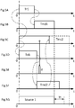
- the Figures 3A to 3G represent switch control timing diagrams in a first case of power transfer in nominal operation, that is to say without fault.
- the figure 3G is a timing diagram illustrating the presence of the first source 1 and its disappearance during a transfer time Tt then the appearance of the second power source 2.
- the sum of the third operating time Tmd1 to disconnect the first source 1, that is to say to open the first switch 4, and the transfer time Tt is less than the second operating time Tmc2 to connect the second source 2, that is to say to close the second switch 5.
- a first time delay Tr1 is applied before the maneuver to disconnect the first source 1, that is to say before a command of the first switch 4.
- Tr 1 tmc 2 - tmd 1 + tt
- the first timer Tr1 must be positive. Therefore it is necessary that: tmc 2 - tmd 1 + tt > 0 and so tmc 2 > tmd 1 + tt
- the second time delay Tr2 must be positive and therefore: tmd 1 + tt > tmc 2
- the transfer time Tt chosen is preferably between 10 milliseconds and 50 milliseconds.
- the “ready to close” contact delivers the closing indicator If ahead of other types of auxiliary contacts, which justifies preferential use.
- the closing indicator If is delivered after a predefined duration following a command to close the second switch.
- an observation window is open, for an observation time Tob, parallel to a command to close the second switch 5, as shown in the 3D figures and 4D .
- the closing indicator If is delivered during the observation period Tob, the closing operation of the second switch can continue.
- the closing indicator If of the second switch 5 is not delivered for the duration Tob of the observation time window, then there is probably a problem of closing the second switch 5 and an opening of the second switch 5 is ordered to not connect the second source 2 following a second scenario.
- the installation and the motors 9 are thus protected from overcurrents and disturbances linked to a transfer duration greater than the predefined transfer duration Tt.
- the second scenario is illustrated by the chronograms represented in Figures 5A to 5G , for which Tmc2> (Tmd1 + Tt).
- the Tob duration observation window is opened simultaneously with the command to close the second switch, as shown in figure 5D .
- the If closing indicator is issued outside the observation window.
- the second switch 5 therefore took longer than expected to execute the closing maneuver, this is an abnormal situation, there is a fault.
- the first scenario is illustrated by the chronograms represented in Figures 4A to 4G , for which Tmc2 ⁇ (Tmd1 + Tt).
- the second time delay Tr2 is started before the maneuver to connect the second source 2 as shown in Figure 4B and 4C , and, in the same way as for the second scenario, the observation window of duration Tob is opened simultaneously with the command to close the second switch, as shown in figure 4D .
- the closing indicator If is issued during the Tob opening time of the observation window, as shown in figure 4D and 4E , the closing operation of the second switch can continue, as shown in figure 4C .
- the chronogram in figure 4G illustrates the disconnection of the first source 1 then the source transfer period followed by the connection of the second source 2.
- the timing diagram in figure 4F illustrates that the cancellation of the connection of the second source 2 was not carried out.
- the process for transferring the power supply of an electrical distribution line 7, from the first source 1 to the second source 2, without overlap, is shown in the form of a flowchart in figure 6 .
- the method includes the step of measuring 100 of the maneuver times Tmc1, Tmc2, Tmd1, Tmd2, to connect and disconnect the first and second sources.
- This measurement step 100 is carried out when the electrical installation is put into service and can be carried out periodically to update the measurements and take into account the wear of the equipment.
- the process continues with two phases initialized simultaneously and taking place in parallel.
- the first phase 200 of connection of the second source 2 begins with a test step 210 if Tmc2 is less than the sum (Tmd1 + Tt). If this is the case, the connection maneuver of the second source 2 is faster than the maneuver disconnection of the first source 1 to which is added the transfer time Tt, then the method goes to step 220 of time delay during the duration Tr2 equal to (Tmd1 + Tt) - Tmc2. If this is not the case, the method continues with step 230 corresponding to the launching of the connection operation of the second source 2 and step 240, executed in parallel with step 230, corresponding to the opening from the observation window. During steps 250 and 260, the method monitors whether the closing indicator If is delivered during the period Tob of opening the observation window.
- the method ends with a step 290 corresponding to a source transfer carried out correctly. If the closing indicator If has not been delivered during the time Tob opening the observation window, the method commands a maneuver to disconnect the second source 2 during a step 270 and the method ends with a step 280 corresponding to a canceled source transfer.
- the second phase 300 of disconnecting the first source 3 from the distribution line 7 begins with a step 310 to test whether Tmc2 is greater than the sum (Tmd1 + Tt). If this is the case, the method goes to step 320 of time delay for the duration Tr1 equal to Tmc2 - (Tmd1 + Tt) then goes to step 330 at the end of the time delay Tr1. If this is not the case, the method continues directly with step 330 corresponding to the launching of the maneuver to disconnect the first source 1.
- the first phase 200 of connection of the second source 2 takes place without passing to step 220 of time delay for the duration Tr2 and the second phase 300 takes place in parallel without passing to l step 320 of time delay during the duration Tr1.
- the process which is the subject of the invention therefore makes it possible to transfer the supply of electrical energy to an electrical distribution line 7, from a first source 1 to a second source 2, during the predefined and controlled transfer time Tt , independent of the time required for the switches to operate. In the event that the transfer time Tt cannot be observed, then the switching of sources is canceled.
- the method described above can be transposed to transfer the supply of electrical energy from the electrical distribution line from the second source to the first source, or alternatively to transfer the supply of electrical energy between two portions of the distribution line. 7, 7b as shown in figure 2 , or any other electrical network configuration.
- a procedure for verifying the opening of the first switch 4 could be carried out during said disconnection maneuver.
- the first source 1 does not disconnect, the source transfer is performed with overlap.
- the first source and the second source being synchronized, the disturbances borne by the loads connected to the supply line will be limited.
- protection must be put in place to limit the mutual influence of the two sources.
- the source inverter 60 can optionally include a man-machine interface 62 intended to supply data for example on the state of the switches, carry out measurements of mean operating time values or allow an operator to initiate the process. source transfer.
- a man-machine interface 62 intended to supply data for example on the state of the switches, carry out measurements of mean operating time values or allow an operator to initiate the process. source transfer.
- a command to activate an actuator by means of an alternating voltage introduces a random delay linked to the phase angle of the alternating voltage at the time of the command.
- Such a delay, included in the maneuver time to connect or disconnect the first or second source would introduce unwanted variability at the first, second, third and fourth maneuver times Tmd1, Tmd2, Tmc1, Tmc2.
- Activation by DC voltage eliminates this variability.
- the first opening actuator 52a of the first switch 4, the second opening actuator 52b of the second switch 5, the first closing actuator 51a of the first switch 4 and the second closing actuator 51b of the second switch 5 are activated by continuous tension.
- the source inverter 60 emits a DC voltage on the fifth link 55a to control the first closing actuator 51a of the first switches 4, the source inverter 60 emits a DC voltage on the sixth link 55b to control the second closing actuator 51b of the second switch 5.
- the source inverter 60 also emits a DC voltage on the third link 56a to control the first opening actuator 52a of the first switch 4, and the source inverter 60 also emits a DC voltage on the fourth link 56b for controlling the second opening actuator 52b of the second switches 5.
- the figure 8 shows such an electric switch in the form of a block diagram illustrating the particular arrangement of the opening 42 and closing 46 mechanisms of the electrical contacts: the actuation of the opening mechanism 42 of the electrical contacts acts on the closing mechanism 46 of the contacts to interrupt a closing movement of said contacts.
- This feature makes it possible to execute the step 270 of maneuvering to disconnect the second source 2, given that the closing indicator If has not been delivered during the time Tob opening the observation window, then that a maneuver for connection to the second source 2 had been engaged previously in step 230.
- the opening mechanism 42 operates on the principle of a first toggle: it comprises a first part 42b movable around a first axis 42a which can move in a first gusset. A first end of said first part 42b carries a first articulation 42c with a second movable part 42d around a second axis 42 e which can move in a second gusset.
- the closing mechanism 46 operates on the principle of a second toggle joint: a third part 46a movable around a third axis 46b carries electrical contacts 41 at one of its ends, the other end carrying a second articulation 46c with the first Exhibit 42b.
- the first closing actuator 51a acts on the third part at the level of the second articulation 46c in the direction indicated by the arrow to obtain the closure of the electrical contacts 41.
- the first opening actuator 52a acts on the first movable part and the second moving part at the level of the first articulation 42c. Activation of the first opening actuator 52a causes the third part 46a to rotate in the direction of opening of the contacts 41.
- a spring 43 keeps the first and the second toggle joint in a stable position in the absence of an opening command or closing contacts. The clever arrangement of the first and of the second toggle joint thus makes it possible to cancel a maneuver for closing the contacts 41 when a maneuver for disconnecting the second source 2 is ordered during a step 270.
- the opening mechanism 42 and the closing mechanism 46 described above are preferred embodiments, however other mechanical principles allowing cancellation of closing of the contacts 41 by an opening command can be used.
- the energy transfer method and the source inverter which is the subject of the invention can be used on networks comprising single-phase or three-phase sources, without limitation linked to the frequency of the sources nor to the power of the loads to be supplied. .
- the energy transfer method and the source inverter which are the subject of the invention are more particularly suitable for transferring the supply of electrical energy to an electrical distribution line to which motors, a first source to a second source, without overlapping from one source to the other and guaranteeing a short and controlled transfer time.
- Conventional switches such as power circuit breakers can be used, without requiring special properties of speed of operation. Under these conditions, the source reverser is produced with standard, economically advantageous products, for which the availability of maintenance parts is guaranteed.
Landscapes
- Engineering & Computer Science (AREA)
- Power Engineering (AREA)
- Business, Economics & Management (AREA)
- Emergency Management (AREA)
- Remote Monitoring And Control Of Power-Distribution Networks (AREA)
- Supply And Distribution Of Alternating Current (AREA)
- Control Of Multiple Motors (AREA)
- Control Of Ac Motors In General (AREA)
Abstract
L'invention porte sur un procédé pour transférer, pendant une durée de transfert prédéfinie, l'alimentation en énergie électrique d'une ligne de distribution électrique (7), d'une première source (1) à une seconde source (2), sans recouvrement des deux sources.L'invention porte également sur un inverseur de sources mettant en oeuvre un tel procédé.The invention relates to a method for transferring, during a predefined transfer period, the supply of electrical energy to an electrical distribution line (7), from a first source (1) to a second source (2), without overlapping of the two sources. The invention also relates to a source inverter implementing such a method.
Description
L'invention concerne un procédé pour transférer l'alimentation en énergie électrique d'une ligne de distribution électrique, d'une première source à une seconde source. L'invention concerne également un inverseur de sources destiné à commander au moins un premier interrupteur et un second interrupteur pour connecter, sans recouvrement, des sources d'énergie électrique à une ligne de distribution de l'énergie.The invention relates to a method for transferring the power supply of an electrical distribution line from a first source to a second source. The invention also relates to a source inverter intended to control at least a first switch and a second switch for connecting, without overlap, sources of electrical energy to an energy distribution line.
La disponibilité de l'énergie électrique est importante, par exemple pour les industries de production en flux continu. En effet, une coupure d'alimentation en énergie électrique peut générer des perturbations pouvant être à l'origine d'un arrêt d'une chaîne de production. Pour disposer d'une alimentation sécurisée et éviter de telles conséquences, un dispositif appelé généralement « inverseur de sources » est utilisé : dès qu'une première source d'énergie présente un risque de disparition, par exemple à cause d'une surchauffe d'un transformateur MT/BT, l'inverseur de sources commute l'arrivée de l'énergie électrique sur une seconde source d'énergie. Cette seconde source est une sortie d'un transformateur redondant de l'installation électrique, ou une ligne électrique de secours, ou encore un générateur autonome. Le transfert de la source d'alimentation en énergie électrique d'une première source à une seconde source nécessite que la première source et la seconde source soient synchronisées c'est-à-dire que l'amplitude et la phase de la première source et de la seconde source doivent être identiques, ou comprises entre certaines limites, au moment de la commutation. Cependant, même dans ce cas, des perturbations importantes peuvent apparaître quand des moteurs sont connectés sur la ligne d'alimentation. En effet, quand l'alimentation d'un moteur électrique disparaît, l'inertie mécanique du moteur et de sa charge ainsi que la rémanence magnétique du rotor amènent le moteur dans un mode de fonctionnement en générateur qui tend à compenser la source défaillante. La vitesse de rotation du moteur décroit plus ou moins rapidement en fonction du couple résistant qui s'oppose à l'inertie de l'ensemble moteur et charge. La fréquence et la phase de la tension fournies par le moteur s'éloignent de la fréquence et de la phase du réseau. Une ré-alimentation par une source d'énergie ayant une fréquence et/ou une phase différente provoque surtensions, surintensités et à-coups mécaniques pouvant affecter le moteur ou l'installation électrique. Les effets sont encore amplifiés quand plusieurs moteurs sont alimentés par la même source d'énergie. Il est donc fondamental d'effectuer le transfert de source le plus rapidement possible, de préférence pendant une durée de transfert prédéfinie, suffisamment longue pour que les transitoires liées à une déconnexion d'une source puissent s'annuler ou s'atténuer fortement, et suffisamment courte pour que le/les moteurs n'aient pas le temps de ralentir de manière trop importante. Une durée de transfert de quelques dizaines de millisecondes est optimale pour des équipements industriels de puissance comprenant des moteurs.The availability of electrical energy is important, for example for the continuous flow production industries. In fact, a cut in the supply of electrical energy can generate disturbances that can be the cause of a production chain shutdown. To have a secure power supply and avoid such consequences, a device generally called a "source inverter" is used: as soon as a first source of energy presents a risk of disappearance, for example due to overheating of a MV / LV transformer, the source inverter switches the arrival of electrical energy to a second energy source. This second source is an output of a redundant transformer of the electrical installation, or an emergency power line, or even an autonomous generator. The transfer of the electric power supply source from a first source to a second source requires that the first source and the second source be synchronized, that is to say that the amplitude and the phase of the first source and of the second source must be identical, or between certain limits, at the time of switching. However, even in this In this case, significant disturbances can appear when motors are connected to the supply line. When the power supply to an electric motor disappears, the mechanical inertia of the motor and its load as well as the magnetic remanence of the rotor bring the motor into a generator operating mode which tends to compensate for the faulty source. The rotational speed of the motor decreases more or less rapidly depending on the resistive torque which opposes the inertia of the motor and load assembly. The frequency and phase of the voltage supplied by the motor deviate from the frequency and phase of the network. A re-supply by an energy source having a different frequency and / or phase causes overvoltages, overcurrents and mechanical jolts which can affect the motor or the electrical installation. The effects are further amplified when several motors are powered by the same energy source. It is therefore essential to carry out the source transfer as quickly as possible, preferably for a predefined transfer duration, long enough for the transients linked to a disconnection from a source to be able to cancel or to be greatly attenuated, and short enough so that the engine (s) do not have time to slow down too much. A transfer time of a few tens of milliseconds is optimal for industrial power equipment including motors.
Le document
Le document
L'invention a pour objet un procédé et un dispositif inverseur de sources pour des charges telles que des moteurs de forte puissance permettant de garantir une commutation rapide d'une source défaillante vers une source de secours, ou inversement quand la source défaillante a retrouvé ses propriétés nominales.The subject of the invention is a method and a source reversing device for loads such as high power motors making it possible to guarantee rapid switching from a faulty source to a backup source, or vice versa when the faulty source has recovered its nominal properties.
L'invention porte sur un procédé pour transférer, pendant une durée de transfert prédéfinie, l'alimentation en énergie électrique d'une ligne de distribution électrique, d'une première source à une seconde source, sans recouvrement des deux sources, un premier interrupteur, relié d'une part à la première source et d'autre part à la ligne de distribution, étant commandé pour se fermer ou s'ouvrir afin de connecter ou déconnecter la première source à la ligne de distribution, un second interrupteur, relié d'une part à la seconde source et d'autre part à la ligne de distribution, étant commandé pour se fermer ou s'ouvrir afin de connecter ou déconnecter la seconde source à ladite ligne de distribution,
tel que :
- soit une première temporisation est appliquée avant une commande d'ouverture du premier interrupteur,
- soit une seconde temporisation est appliquée avant une commande de fermeture du second interrupteur,
such as :
- either a first time delay is applied before a command to open the first switch,
- either a second time delay is applied before a command to close the second switch,
Avantageusement, le procédé comporte une étape de calcul :
- d'une valeur moyenne d'une première durée de manoeuvre pour connecter la première source à la ligne de distribution,
- d'une valeur moyenne d'une deuxième durée de manoeuvre pour connecter la seconde source à la ligne de distribution,
- d'une valeur moyenne d'une troisième durée de manoeuvre pour déconnecter la première source de la ligne de distribution, et
- d'une valeur moyenne d'une quatrième durée de manoeuvre pour déconnecter la seconde source de la ligne de distribution.
- an average value of a first operating time to connect the first source to the distribution line,
- an average value of a second operating time to connect the second source to the distribution line,
- an average value of a third operating time to disconnect the first source from the distribution line, and
- of an average value of a fourth operating time to disconnect the second source from the distribution line.
Avantageusement, la première temporisation est appliquée avant la commande d'ouverture du premier interrupteur quand la deuxième durée de manoeuvre pour connecter la seconde source est supérieure à la somme de la troisième durée de manoeuvre pour déconnecter la première source et de la durée de transfert.Advantageously, the first time delay is applied before the command to open the first switch when the second operating time to connect the second source is greater than the sum of the third operating time to disconnect the first source and the transfer time.
De préférence, la première temporisation est égale à la deuxième durée de manoeuvre pour connecter la seconde source moins la somme de la troisième durée de manoeuvre pour déconnecter la première source et de la durée de transfert.Preferably, the first time delay is equal to the second operating time to connect the second source minus the sum of the third operating time to disconnect the first source and the transfer time.
Avantageusement, la seconde temporisation est appliquée avant la commande de fermeture du second interrupteur quand la deuxième durée de manoeuvre pour connecter la seconde source est inférieure à la somme de la troisième durée de manoeuvre pour déconnecter la première source et de la durée de transfert.Advantageously, the second time delay is applied before the command to close the second switch when the second operating time to connect the second source is less than the sum of the third operating time to disconnect the first source and the transfer time.
De préférence, la seconde temporisation est égale à la somme de la troisième durée de manoeuvre pour déconnecter la première source et de la durée de transfert moins la deuxième durée de la manoeuvre pour connecter la seconde source.Preferably, the second time delay is equal to the sum of the third operating time to disconnect the first source and the transfer time minus the second operating time to connect the second source.
Préférentiellement, la durée de transfert est comprise entre 10 ms et 50 ms.Preferably, the transfer time is between 10 ms and 50 ms.
Préférentiellement, une fenêtre d'observation d'une durée d'observation prédéfinie est ouverte simultanément avec la commande de fermeture du second interrupteur. De préférence, une ouverture du second interrupteur est commandée quand un indicateur de fermeture du second interrupteur n'est pas délivré pendant la durée d'observation.Preferably, an observation window with a predefined observation duration is opened simultaneously with the command to close the second switch. Preferably, an opening of the second switch is commanded when an indicator for closing the second switch is not issued during the observation period.
Préférentiellement, l'indicateur de fermeture du second interrupteur est délivré pendant une exécution d'un mouvement de fermeture des contacts dudit second interrupteur.Preferably, the closing indicator of the second switch is delivered during an execution of a closing movement of the contacts of said second switch.
Selon une première variante, l'indicateur de fermeture du second interrupteur est délivré quand des contacts dudit second interrupteur sont fermés.According to a first variant, the closing indicator of the second switch is delivered when the contacts of said second switch are closed.
Selon une seconde variante, l'indicateur de fermeture du second interrupteur est délivré quand des contacts dudit second interrupteur ne sont plus ouverts.According to a second variant, the closing indicator of the second switch is delivered when the contacts of said second switch are no longer open.
L'invention a également pour objet un inverseur de sources destiné à commander au moins un premier interrupteur et un second interrupteur pour transférer, sans recouvrement, l'alimentation en énergie électrique d'une ligne de distribution de l'énergie d'une première source à une seconde source (2),
le premier interrupteur comportant au moins :
- un premier actionneur de fermeture pour commander une manoeuvre de fermeture du premier interrupteur,
- un premier actionneur d'ouverture pour commander une manoeuvre d'ouverture du premier interrupteur, et
- un premier capteur pour fournir un premier signal indicateur de fermeture du premier interrupteur,
- un second actionneur de fermeture pour commander une manoeuvre de fermeture du second interrupteur,
- un second actionneur d'ouverture pour commander une manoeuvre d'ouverture du second interrupteur, et
- un second capteur pour fournir un second signal indicateur de fermeture du second interrupteur,
- au moins une première liaison connectée au premier capteur pour recevoir un premier signal indicateur de fermeture du premier interrupteur et une deuxième liaison pour recevoir un second signal indicateur de fermeture du second interrupteur,
- au moins une troisième liaison pour commander le premier actionneur d'ouverture et une quatrième liaison pour commander le second actionneur d'ouverture,
- au moins une cinquième liaison pour commander le premier actionneur de fermeture et une sixième liaison pour commander le second actionneur de fermeture, et
- une unité de traitement pour la mise en oeuvre du procédé de connexion tel que décrit précédemment.
the first switch comprising at least:
- a first closing actuator for controlling a closing operation of the first switch,
- a first opening actuator for controlling an opening operation of the first switch, and
- a first sensor for supplying a first signal indicating that the first switch is closed,
- a second closing actuator for controlling a closing operation of the second switch,
- a second opening actuator for controlling an opening operation of the second switch, and
- a second sensor for supplying a second signal indicating that the second switch is closed,
- at least a first link connected to the first sensor to receive a first signal indicating that the first switch is closed and a second link to receive a second signal indicating that the second switch is closing,
- at least a third connection for controlling the first opening actuator and a fourth connection for controlling the second opening actuator,
- at least a fifth connection for controlling the first closing actuator and a sixth connection for controlling the second closing actuator, and
- a processing unit for implementing the connection method as described above.
De préférence, les premier et second actionneurs de fermeture des premier et second interrupteurs sont activés par une tension continue et l'inverseur de source émet une tension continue sur les cinquième et sixième liaisons pour commander respectivement les premier et second actionneurs de fermeture du premier et du second interrupteur.Preferably, the first and second closing actuators of the first and second switches are activated by a DC voltage and the source inverter emits a DC voltage on the fifth and sixth connections to respectively control the first and second closing actuators of the first and of the second switch.
De préférence, les premier et second actionneurs d'ouverture des premier et second interrupteurs sont activés par une tension continue et l'inverseur de source émet une tension continue sur les troisième et quatrième liaisons pour commander respectivement les premier et second actionneurs d'ouverture du premier et du second interrupteur.Preferably, the first and second opening actuators of the first and second switches are activated by a DC voltage and the source inverter emits a DC voltage on the third and fourth links to respectively control the first and second opening actuators of the first and second switch.
L'invention concerne également un interrupteur électrique, destiné à être commandé par un inverseur de source tel que décrit précédemment, ledit interrupteur comportant au moins :
- au moins une borne de raccordement amont destinée à être connectée à une source fournissant une énergie électrique,
- au moins une borne de raccordement aval destinée à être connectée à une ligne de distribution d'énergie électrique,
- des contacts électriques pour établir ou interrompre la circulation d'énergie entre au moins la borne amont et la borne aval,
- un actionneur d'ouverture pour actionner un mécanisme d'ouverture des contacts électriques,
- un actionneur de fermeture pour actionner un mécanisme de fermeture des contacts électriques,
- at least one upstream connection terminal intended to be connected to a source supplying electrical energy,
- at least one downstream connection terminal intended to be connected to an electrical energy distribution line,
- electrical contacts to establish or interrupt the flow of energy between at least the upstream terminal and the downstream terminal,
- an opening actuator for actuating a mechanism for opening the electrical contacts,
- a closing actuator for actuating a mechanism for closing the electrical contacts,
D'autres avantages et caractéristiques ressortiront plus clairement de la description qui va suivre, de modes particuliers de réalisation de l'invention, donnés à titre d'exemples non limitatifs, et représentés aux dessins annexés sur lesquels :
- la
figure 1 est une représentation schématique d'une première configuration d'installation électrique permettant un transfert d'une première source vers une seconde source au moyen de deux interrupteurs, - la
figure 2 est une représentation schématique d'une variante de configuration d'installation électrique permettant un transfert de sources, - les
figures 3A à 3G représentent des chronogrammes de commande des interrupteurs, d'apparition de signaux et d'états des sources dans un premier cas de transfert d'alimentation sans défaut, - les
figures 4A à 4G représentent des chronogrammes de commande des interrupteurs, d'apparition de signaux et d'états des sources dans un second cas de transfert d'alimentation sans défaut, - les
figures 5A à 5G représentent des chronogrammes de commande des interrupteurs, d'apparition de signaux et d'états des sources dans un cas de transfert d'alimentation pour lequel une durée de transfert prédéfinie ne peut être respectée, - la
figure 6 représente, sous la forme d'un organigramme, un procédé de commande de deux interrupteurs pour effectuer un transfert d'alimentation en énergie électrique d'une première source à une seconde source, - la
figure 7 représente un schéma bloc d'un inverseur de sources représentant les connections d'entrée/sortie pour la mise en oeuvre du procédé de commande de deux interrupteurs, - la
figure 8 représente un interrupteur électrique sous forme d'un synoptique pour illustrer le fonctionnement d'un mécanisme d'ouverture et de fermeture de contacts électriques.
- the
figure 1 is a schematic representation of a first configuration of electrical installation allowing transfer from a first source to a second source by means of two switches, - the
figure 2 is a schematic representation of a variant configuration of electrical installation allowing transfer of sources, - the
Figures 3A to 3G represent timing diagrams of switch control, appearance of signals and source states in a first case of faultless power transfer, - the
Figures 4A to 4G represent timing diagrams of switch control, appearance of signals and source states in a second case of faultless power transfer, - the
Figures 5A to 5G represent timing diagrams of switch control, appearance of signals and source states in a case of power transfer for which a predefined transfer time cannot be respected, - the
figure 6 represents, in the form of a flowchart, a method of controlling two switches for effecting a transfer of electric power supply from a first source to a second source, - the
figure 7 represents a block diagram of a source inverter representing the input / output connections for implementing the method for controlling two switches, - the
figure 8 shows an electrical switch in the form of a block diagram to illustrate the operation of an opening and closing mechanism of electrical contacts.
La
En cas de prévision d'indisponibilité ou d'action volontaire d'ouverture de la première source 1, par exemple suite à une surcharge en amont de l'installation, une seconde source 2 d'énergie électrique est utilisée pour continuer à alimenter les charges 8, 9. Cette seconde source peut être, par exemple, un générateur local tel qu'un groupe électrogène, une seconde ligne électrique ou encore une sortie d'un transformateur redondant de l'installation électrique. Un second interrupteur 5, connecté en amont à la seconde source 2 et en aval à la ligne de distribution 7, est commandé pour se fermer ou s'ouvrir afin de connecter ou déconnecter la seconde source 2 à ladite ligne de distribution 7. Dans le cas où le second interrupteur 5 est fermé pour connecter la seconde source 2 à la ligne de distribution 7, le premier interrupteur 4 est ouvert de façon à ce qu'il n'y ait pas d'interaction entre la première source 1 et la deuxième source 2, tout particulièrement lorsque la première source 1 redevient disponible. Le second interrupteur 5 est préférentiellement similaire au premier interrupteur 4. En variante, ainsi que représenté en
Pour éviter toute perturbation d'une source sur l'autre, le premier interrupteur 4 est ouvert avant la fermeture du second interrupteur 5 de manière à éviter toute circulation de courant, même fugitivement, entre la première source 1 et la seconde source 2. Ce séquencement permet un transfert de source appelé « sans recouvrement », c'est-à-dire que la première source et la deuxième source ne sont jamais connectées simultanément ensemble à la ligne de distribution 7. De plus, le procédé selon l'invention garantit une durée de transfert Tt prédéfinie, c'est-à-dire que les contacts de l'interrupteur 5 sont fermés après une durée de transfert Tt suivant l'ouverture des contacts du premier interrupteur 4. Ainsi, des moteurs connectés à la ligne de distribution 7 ne verront pas d'interruption de leur alimentation en énergie supérieure à la durée de transfert Tt. En optimisant cette durée de transfert, les moteurs subissent des perturbations minimales lors du transfert de source. En revanche, si la durée de transfert Tt ne peut être respectée alors les opérations de transfert de sources sont annulées. En effet, les conséquences d'un redémarrage différé de moteurs sont généralement moins critiques qu'un transfert de sources trop long.To avoid any disturbance from one source to the other, the
Les opérations de transfert de sources doivent également durer le moins de temps possible pour que le transfert soit effectué avant que la source défaillante n'ait complétement disparu. Compte tenu de durée de manoeuvre généralement longues, par exemple quand les interrupteurs sont des disjoncteurs de forte puissance, l'ouverture du premier interrupteur 4 est commandée parallèlement à une fermeture du second interrupteur 5. Pour cadencer efficacement les manoeuvres en tenant compte des durées nécessaires aux différentes manoeuvres et au respect de la durée de transfert Tt, le procédé comporte une étape préalable de mesure d'une moyenne des durées de manoeuvre des interrupteurs. Une durée de manoeuvre correspond au temps écoulé entre l'instant ou une commande est donnée et l'instant ou les contacts de l'interrupteur commandé sont dans l'état demandé par la commande. Une durée de manoeuvre est de l'ordre de quelques dizaines de millisecondes pour les interrupteurs. Pour un même interrupteur, une durée de manoeuvre d'ouverture des contacts électriques est différente d'une durée de manoeuvre de fermeture desdits contacts électriques. Généralement, la durée de manoeuvre d'ouverture est inférieure à la durée de manoeuvre de fermeture. D'autre part, la durée d'une manoeuvre donnée est soumise à une variabilité liée au fonctionnement mécanique de l'interrupteur exécutant ladite manoeuvre. Pour limiter cette variabilité, le procédé de l'invention comporte une étape de calcul 100 d'une valeur moyenne d'une première durée de manoeuvre Tmc1 pour connecter la première source à la ligne de distribution 7, d'une valeur moyenne d'une deuxième durée de manoeuvre Tmc2 pour connecter la seconde source à la ligne de distribution 7, d'une valeur moyenne d'une troisième durée de manoeuvre Tmd1 pour déconnecter la première source de la ligne de distribution 7, et d'une valeur moyenne d'une quatrième durée de manoeuvre Tmd2 pour déconnecter la seconde source de la ligne de distribution 7. Le calcul d'une valeur moyenne d'une durée de manoeuvre est effectué quand l'installation électrique est hors tension ou quand les charges 8, 9 ne sont pas connectées. Ladite manoeuvre est répétée plusieurs fois afin d'obtenir plusieurs mesures. Un résultat de calcul d'une moyenne des mesures est mémorisé par le procédé pour être prise en compte dans la suite du procédé de connexion. Il est possible également d'utiliser la durée mesurée le plus fréquemment au cours de la série de manoeuvres.Source transfer operations must also last as little time as possible for the transfer to be carried out before the faulty source has completely disappeared. In view of the generally long operating times, for example when the switches are high-power circuit breakers, the opening of the
Les ![]()
![]()
La troisième durée de manoeuvre Tmd1 pour déconnecter la première source 1 est mesurée, la deuxième durée de manoeuvre Tmc2 pour connecter la seconde source 2 est également mesurée, la durée de transfert Tt est choisie, il est donc simple de calculer la valeur de la première temporisation Tr1 : ![]()
![]()
Pour être appliquée, la première temporisation Tr1 doit être positive. Par conséquent il est nécessaire que : ![]()
![]()
![]()
![]()
Evidemment, quand Tmc2 = (Tmd1 +Tt), la première temporisation Tr1 est nulle, et par conséquent la manoeuvre pour déconnecter la première source 1 est lancée au même instant que la manoeuvre pour connecter la seconde source 2.Obviously, when Tmc2 = (Tmd1 + Tt), the first time delay Tr1 is zero, and therefore the maneuver to disconnect the
Un fonctionnement semblable est appliqué quand la deuxième durée de manoeuvre Tmc2 pour connecter la seconde source 2 est inférieure à la somme de la troisième durée de manoeuvre Tmd1 pour déconnecter la première source 1 et de la durée de transfert Tt. Dans ce cas, une seconde temporisation Tr2 est appliquée avant la manoeuvre pour connecter la seconde source 2 par la fermeture du second interrupteur 5. Cette configuration est illustrée par les chronogrammes des ![]()
![]()
Pour pouvoir être appliquée, la seconde temporisation Tr2 doit être positive et par conséquent: ![]()
![]()
En synthèse, quand Tmc2 > (Tmd1 +Tt) alors la première temporisation Tr1 doit être appliquée avant le lancement de la manoeuvre pour déconnecter la première source 1 ce qui correspond à l'ouverture du premier interrupteur 4. Quand Tmc2 < (Tmd1 +Tt) alors la seconde temporisation Tr2 doit être appliquée avant le lancement de la manoeuvre pour connecter la seconde source 2 par la fermeture du second interrupteur 5. Ainsi, l'intervalle de temps entre la déconnexion de la première source 1, correspondant à l'ouverture du premier interrupteur 4, et la connexion de la seconde source 2, correspondant à la fermeture du second interrupteur 5, ledit intervalle de temps est égal à la durée de transfert Tt. Quand Tmc2 = (Tmd1 +Tt), aucune temporisation n'est appliquée, la manoeuvre pour déconnecter la première source 1 est commandée simultanément avec la manoeuvre pour connecter la seconde source 2.In summary, when Tmc2> (Tmd1 + Tt) then the first time delay Tr1 must be applied before the start of the maneuver to disconnect the
La durée de transfert Tt choisie est préférentiellement comprise entre 10 millisecondes et 50 millisecondes.The transfer time Tt chosen is preferably between 10 milliseconds and 50 milliseconds.
Le procédé comporte une possibilité d'annulation du transfert de sources dans le cas où la durée de transfert ne peut être respectée. Il est effectivement important de ne pas connecter la deuxième source 2 si la durée de transfert est supérieure à la durée de transfert Tt prédéfinie. En effet, au-delà de ladite durée de transfert prédéfinie, l'écart de fréquence et de phase entre la deuxième source 2 et les bornes des moteurs 9 connectés à la ligne de distribution 7 peut devenir trop important et une connexion, dans ces conditions, des moteurs 9 à la deuxième source 2 risque de provoquer des surintensités dangereuses. Pour éviter cela, un indicateur de fermeture If du second interrupteur est surveillé. Cet indicateur est délivré par le second interrupteur 5 pour indiquer un état favorable à une fermeture. L'indicateur de fermeture If du second interrupteur 5 est délivré quand le mécanisme de fermeture des contacts du second interrupteur exécute un mouvement de fermeture. De préférence un contact auxiliaire de disjoncteur appelé « prêt à fermer », également désigné par l'acronyme « PF », est utilisé pour fournir l'indicateur de fermeture. Il est possible d'utiliser d'autres types de contacts auxiliaires pour fournir l'indicateur de fermeture :
- un contact auxiliaire de position de type « normalement fermé » également désigné par l'acronyme « NF » fournit un indicateur quand des contacts de l'interrupteur sont fermés, ou
- un contact auxiliaire de position « normalement ouvert » également désigné par l'acronyme « NO », fournit un indicateur dès que les contacts de l'interrupteur ne sont plus ouverts.
- an "normally closed" type auxiliary position contact also designated by the acronym "NF" provides an indicator when the switch contacts are closed, or
- an auxiliary “normally open” position contact, also known by the acronym “NO”, provides an indicator as soon as the switch contacts are no longer open.
Le contact « prêt à fermer » délivre l'indicateur de fermeture If en avance par rapport aux autres types de contacts auxiliaires ce qui justifie une utilisation préférentielle.The “ready to close” contact delivers the closing indicator If ahead of other types of auxiliary contacts, which justifies preferential use.
Dans un premier scénario, l'indicateur de fermeture If est délivré après une durée prédéfinie suivant une commande de fermeture du second interrupteur. Afin d'être certain de pouvoir respecter la durée de transfert Tt, une fenêtre d'observation est ouverte, pendant une durée d'observation Tob, parallèlement à une commande de fermeture du second interrupteur 5, ainsi que représenté sur les
Le premier scénario est illustré par les chronogrammes représentés en
Le procédé pour transférer l'alimentation en énergie électrique d'une ligne de distribution électrique 7, de la première source 1 à la seconde source 2, sans recouvrement, est représenté sous forme d'un organigramme en
La première phase 200 de connexion de la seconde source 2 commence par une étape 210 de test si Tmc2 est inférieur à la somme (Tmd1+Tt). Si c'est le cas, la manoeuvre de connexion de la seconde source 2 est plus rapide que la manoeuvre de déconnexion de la première source 1 à laquelle est ajouté le temps de transfert Tt, alors le procédé passe à l'étape 220 de temporisation pendant la durée Tr2 égale à (Tmd1 +Tt) - Tmc2. Si ce n'est pas le cas, le procédé se poursuit par l'étape 230 correspondant au lancement de la manoeuvre de connexion de la seconde source 2 et l'étape 240, exécutées parallèlement à l'étape 230, correspondant à l'ouverture de la fenêtre d'observation. Au cours des étapes 250 et 260, le procédé surveille si l'indicateur de fermeture If est délivré pendant la durée Tob d'ouverture de la fenêtre d'observation. Si c'est le cas, le procédé se termine par une étape 290 correspondant à un transfert de source effectué correctement. Si l'indicateur de fermeture If n'a pas été délivré pendant la durée Tob d'ouverture de la fenêtre d'observation, le procédé commande une manoeuvre de déconnexion de la seconde source 2 au cours d'une étape 270 et le procédé se termine par une étape 280 correspondant à un transfert de sources annulé.The
La seconde phase 300 de déconnexion de la première source 3 de la ligne de distribution 7 commence par une étape 310 pour tester si Tmc2 est supérieur à la somme (Tmd1+Tt). Si c'est le cas, le procédé passe à l'étape 320 de temporisation pendant la durée Tr1 égale à Tmc2 - (Tmd1+Tt) puis passe à l'étape 330 à la fin de la temporisation Tr1. Si ce n'est pas le cas, le procédé se poursuit directement par l'étape 330 correspondant au lancement de la manoeuvre de déconnexion de la première source 1.The
Dans le cas où Tmc2 = (Tmd1 +Tt), la première phase 200 de connexion de la seconde source 2 se déroule sans passage à l'étape 220 de temporisation pendant la durée Tr2 et la seconde phase 300 se déroule parallèlement sans passage à l'étape 320 de temporisation pendant la durée Tr1.In the case where Tmc2 = (Tmd1 + Tt), the
Le procédé faisant l'objet de l'invention permet donc de transférer l'alimentation en énergie électrique d'une ligne de distribution électrique 7, d'une première source 1 vers une seconde source 2, pendant la durée de transfert Tt prédéfinie et maîtrisée, indépendante du temps nécessaire au fonctionnement des interrupteurs. Dans le cas où la durée de transfert Tt ne peut être respectée, alors la commutation de sources est annulée. Bien évidemment, le procédé décrit précédemment peut être transposé pour transférer l'alimentation en énergie électrique de la ligne de distribution électrique de la seconde source vers la première source, ou encore pour transférer l'alimentation en énergie électrique entre deux portions de ligne de distribution 7, 7b tel que représenté en
Une procédure de vérification de l'ouverture du premier interrupteur 4 pourrait être effectuée au cours de ladite manoeuvre de déconnexion. Cependant, si la première source 1 ne se déconnecte pas, le transfert de source s'effectue avec recouvrement. La première source et la seconde source étant synchronisées, les perturbations supportées par les charges connectée sur la ligne d'alimentation seront limitées. Cependant une protection doit être mise en place pour limiter l'influence mutuelle des deux sources.A procedure for verifying the opening of the
L'invention concerne également un inverseur de sources 60 destiné à commander au moins un premier interrupteur 4 et un second interrupteur 5 pour connecter, sans recouvrement, au moins deux sources d'énergie électrique 1, 2 à une ligne de distribution de l'énergie 7. La
- au moins une première
liaison 57a connectée à unpremier capteur 54a pour recevoir un premier signal indicateur de fermeture If dupremier interrupteur 4 et une deuxièmeliaison 57b pour recevoir un second signal indicateur de fermeture Ifb dusecond interrupteur 5, - au moins une troisième
liaison 56a pour commander un premier actionneur d'ouverture 52a dupremier interrupteur 4 et une quatrièmeliaison 56b pour commander un second actionneur d'ouverture 52b dusecond interrupteur 5, - au moins une cinquième
liaison 55a pour commander un premier actionneur de fermeture 51 a du premier interrupteur 4et une sixièmeliaison 55b pour commander un second actionneur de fermeture 51b dusecond interrupteur 5, et - une unité de traitement 61 pour la mise en oeuvre du procédé de connexion tel que décrit précédemment.
- at least a
first link 57a connected to afirst sensor 54a to receive a first closing indicator signal If from thefirst switch 4 and asecond link 57b to receive a second closing indicator signal Ifb from thesecond switch 5, - at least a
third link 56a for controlling afirst opening actuator 52a of thefirst switch 4 and afourth link 56b for controlling asecond opening actuator 52b of thesecond switch 5, - at least a
fifth link 55a for controlling afirst closing actuator 51a of thefirst switch 4 and asixth link 55b for controlling asecond closing actuator 51b of thesecond switch 5, and - a
processing unit 61 for implementing the connection method as described above.
L'inverseur de sources 60 peut comporter en option une interface homme-machine 62 destinée à fournir des données par exemple sur l'état des interrupteurs, effectuer des mesures de valeurs moyenne de durée de manoeuvre ou permettre à un opérateur d'initialiser le procédé de transfert de source.The
Une commande pour activer un actionneur au moyen d'une tension alternative introduit un retard aléatoire lié à l'angle de phase de la tension alternative au moment de la commande. Un tel retard, inclus dans la durée de manoeuvre pour connecter ou déconnecter la première ou la seconde source, introduirait une variabilité non souhaitée aux première, deuxième, troisième et quatrième durées de manoeuvre Tmd1, Tmd2, Tmc1, Tmc2. Une activation par une tension continue élimine cette variabilité. Préférentiellement, le premier actionneur d'ouverture 52a du premier interrupteur 4, le second actionneur d'ouverture 52b du second interrupteur 5, le premier actionneur de fermeture 51a du premier interrupteur 4 et le second actionneur de fermeture 51b du second interrupteur 5 sont activés par une tension continue. L'inverseur de source 60 émet une tension continue sur la cinquième liaisons 55a pour commander le premier actionneur de fermeture 51a du premier interrupteurs 4, l'inverseur de source 60 émet une tension continue sur la sixième liaisons 55b pour commander le second actionneur de fermeture 51b du second interrupteurs 5. L'inverseur de source 60 émet aussi une tension continue sur la troisième liaison 56a pour commander le premier actionneur d'ouverture 52a du premier interrupteur 4, et l'inverseur de source 60 émet également une tension continue sur la quatrième liaison 56b pour commander le second actionneur d'ouverture 52b du second interrupteurs 5.A command to activate an actuator by means of an alternating voltage introduces a random delay linked to the phase angle of the alternating voltage at the time of the command. Such a delay, included in the maneuver time to connect or disconnect the first or second source, would introduce unwanted variability at the first, second, third and fourth maneuver times Tmd1, Tmd2, Tmc1, Tmc2. Activation by DC voltage eliminates this variability. Preferably, the
Le premier interrupteur électrique 4 étant destiné à être commandé par l'inverseur de source 60 comporte au moins :
- au moins une borne de raccordement amont 12 destinée à être connectée à une première
source 4 ou à une ligne de transport d'énergie électrique, - au moins une borne de raccordement aval 13 destinée à être connectée à une ligne de
distribution d'énergie électrique 7, - des contacts électriques 41 pour établir ou interrompre la circulation d'énergie entre au moins la borne
amont 12 et la borneaval 13, - un actionneur d'ouverture 52a pour actionner un mécanisme d'ouverture 42 des contacts électriques 41,
- un actionneur de fermeture 51 a pour actionner un mécanisme de fermeture 46 des contacts électriques 41.
- at least one
upstream connection terminal 12 intended to be connected to afirst source 4 or to an electrical energy transport line, - at least one
downstream connection terminal 13 intended to be connected to an electricalenergy distribution line 7, -
electrical contacts 41 to establish or interrupt the flow of energy between at least theupstream terminal 12 and thedownstream terminal 13, - an
opening actuator 52a for actuating amechanism 42 for opening theelectrical contacts 41, - a closing
actuator 51 a for actuating aclosing mechanism 46 of theelectrical contacts 41.
La
Le mécanisme d'ouverture 42 fonctionne selon le principe d'une première genouillère : il comporte une première pièce 42b mobile autour d'un premier axe 42a pouvant se déplacer dans un premier gousset. Une première extrémité de ladite première pièce 42b porte une première articulation 42c avec une deuxième pièce mobile 42d autour d'un deuxième axe 42e pouvant se déplacer dans un second gousset. Le mécanisme de fermeture 46 fonctionne selon le principe d'une seconde genouillère : une troisième pièce 46a mobile autour d'un troisième axe 46b porte des contacts électriques 41 à une de ses extrémités, l'autre extrémité portant une deuxième articulation 46c avec la première pièce 42b. Le premier actionneur de fermeture 51a agit sur la troisième pièce au niveau de la deuxième articulation 46c dans le sens indiqué par la flèche pour obtenir la fermeture des contacts électriques 41. Le premier actionneur d'ouverture 52a agit sur la première pièce mobile et la deuxième pièce mobile au niveau de la première articulation 42c. Une activation du premier actionneur d'ouverture 52a provoque une rotation de la troisième pièce 46a dans le sens de l'ouverture des contacts 41. Un ressort 43 maintient la première et la seconde genouillère en position stable en l'absence de commande d'ouverture ou de fermeture des contacts. L'agencement astucieux de la première et de la seconde genouillère permet ainsi d'annuler une manoeuvre de fermeture des contacts 41 quand une manoeuvre de déconnexion de la seconde source 2 est commandée au cours d'une étape 270. Le mécanisme d'ouverture 42 et le mécanisme de fermeture 46 décrits précédemment sont des modes de réalisation préférentiels cependant d'autres principes mécaniques permettant une annulation de fermeture des contacts 41 par une commande d'ouverture peuvent être employés.The
Le procédé de transfert d'énergie et l'inverseur de sources faisant l'objet de l'invention peuvent être utilisés sur des réseaux comportant des sources monophasées ou triphasées, sans limitation liée à la fréquence des sources ni à la puissance des charges à alimenter. Le procédé de transfert d'énergie et l'inverseur de sources faisant l'objet de l'invention sont plus particulièrement adaptés pour transférer l'alimentation en énergie électrique d'une ligne de distribution électrique sur laquelle sont connectés des moteurs, d'une première source à une seconde source, sans recouvrement d'une source sur l'autre et en garantissant une durée de transfert brève et maîtrisée. Des interrupteurs conventionnels tels que des disjoncteurs de puissance peuvent être employés, sans nécessiter de propriétés particulières de rapidité de manoeuvre. Dans ces conditions, l'inverseur de sources est réalisé avec des produits standards, économiquement avantageux, pour lesquels la disponibilité des pièces de maintenance est assurée. Ces avantages favorisent une utilisation industrielle en grande série d'un tel inverseur de sources.The energy transfer method and the source inverter which is the subject of the invention can be used on networks comprising single-phase or three-phase sources, without limitation linked to the frequency of the sources nor to the power of the loads to be supplied. . The energy transfer method and the source inverter which are the subject of the invention are more particularly suitable for transferring the supply of electrical energy to an electrical distribution line to which motors, a first source to a second source, without overlapping from one source to the other and guaranteeing a short and controlled transfer time. Conventional switches such as power circuit breakers can be used, without requiring special properties of speed of operation. Under these conditions, the source reverser is produced with standard, economically advantageous products, for which the availability of maintenance parts is guaranteed. These advantages encourage large-scale industrial use of such a source inverter.
Claims (16)
le premier interrupteur (4) comportant au moins :
the first switch (4) comprising at least:
Applications Claiming Priority (1)
| Application Number | Priority Date | Filing Date | Title |
|---|---|---|---|
| FR1857401A FR3084973B1 (en) | 2018-08-09 | 2018-08-09 | TRANSFER PROCESS WITHOUT RECOVERY OF ELECTRIC ENERGY SOURCES AND SOURCE INVERTER IMPLEMENTING SUCH A PROCESS |
Publications (2)
| Publication Number | Publication Date |
|---|---|
| EP3609034A1 true EP3609034A1 (en) | 2020-02-12 |
| EP3609034B1 EP3609034B1 (en) | 2021-02-17 |
Family
ID=65201053
Family Applications (1)
| Application Number | Title | Priority Date | Filing Date |
|---|---|---|---|
| EP19180775.9A Active EP3609034B1 (en) | 2018-08-09 | 2019-06-18 | Method for the overlap-free transfer of electric power sources and source changeover switch implementing such a method |
Country Status (5)
| Country | Link |
|---|---|
| US (1) | US11063468B2 (en) |
| EP (1) | EP3609034B1 (en) |
| CN (1) | CN110829573B (en) |
| ES (1) | ES2868275T3 (en) |
| FR (1) | FR3084973B1 (en) |
Citations (8)
| Publication number | Priority date | Publication date | Assignee | Title |
|---|---|---|---|---|
| EP0471178A2 (en) * | 1990-08-14 | 1992-02-19 | International Business Machines Corporation | Power Transfer Unit |
| EP1014534A1 (en) | 1998-12-22 | 2000-06-28 | S & C ELECTRIC COMPANY | Source-transfer switching system and method |
| US20140001860A1 (en) | 2011-02-28 | 2014-01-02 | Zhen Cao | Fast bus transfer method and device |
| CN103683469B (en) * | 2012-09-26 | 2016-04-06 | 力博特公司 | The control method that a kind of uninterrupted power supply input switches and equipment |
| US20160233720A1 (en) * | 2013-12-31 | 2016-08-11 | Lite-On, Inc. | Dual input power supply system and method |
| US9570253B1 (en) * | 2011-11-28 | 2017-02-14 | Amazon Technologies, Inc. | System and method with timing self-configuration |
| US20170090549A1 (en) * | 2015-09-25 | 2017-03-30 | Hon Hai Precision Industry Co., Ltd. | Switch control device and method for power |
| US20170366040A1 (en) * | 2016-06-16 | 2017-12-21 | Eaton Corporation | Transfer switch apparatus and methods using transition time monitoring and adaptation |
Family Cites Families (7)
| Publication number | Priority date | Publication date | Assignee | Title |
|---|---|---|---|---|
| US6051893A (en) * | 1998-10-29 | 2000-04-18 | Mitsubishi Denki Kabushiki Kaisha | Electric power supply system for load |
| CN1599189A (en) * | 2003-09-18 | 2005-03-23 | 帕尔威电力器具公司 | On-line uninterruption source with two relay bypass circuit and its operation method |
| US7535129B2 (en) * | 2006-05-17 | 2009-05-19 | Twinsource, Llc | Method and apparatus for transfer of a critical load from one source to a back up source using magnetically latched relays |
| WO2014134218A1 (en) * | 2013-02-26 | 2014-09-04 | Zonit Structured Solutions, Llc | Parallel redundant power distribution |
| US9419473B2 (en) * | 2013-12-19 | 2016-08-16 | Eaton Corporation | Automatic transfer switch (ATS) bypass switch |
| WO2015152938A1 (en) * | 2014-04-04 | 2015-10-08 | Schneider Electric It Corporation | Systems and methods for quick power delivery mode changes |
| JP6243554B2 (en) * | 2014-12-25 | 2017-12-06 | 東芝三菱電機産業システム株式会社 | Uninterruptible power system |
-
2018
- 2018-08-09 FR FR1857401A patent/FR3084973B1/en not_active Expired - Fee Related
-
2019
- 2019-06-18 EP EP19180775.9A patent/EP3609034B1/en active Active
- 2019-06-18 ES ES19180775T patent/ES2868275T3/en active Active
- 2019-06-28 US US16/456,088 patent/US11063468B2/en active Active
- 2019-08-01 CN CN201910706171.9A patent/CN110829573B/en active Active
Patent Citations (8)
| Publication number | Priority date | Publication date | Assignee | Title |
|---|---|---|---|---|
| EP0471178A2 (en) * | 1990-08-14 | 1992-02-19 | International Business Machines Corporation | Power Transfer Unit |
| EP1014534A1 (en) | 1998-12-22 | 2000-06-28 | S & C ELECTRIC COMPANY | Source-transfer switching system and method |
| US20140001860A1 (en) | 2011-02-28 | 2014-01-02 | Zhen Cao | Fast bus transfer method and device |
| US9570253B1 (en) * | 2011-11-28 | 2017-02-14 | Amazon Technologies, Inc. | System and method with timing self-configuration |
| CN103683469B (en) * | 2012-09-26 | 2016-04-06 | 力博特公司 | The control method that a kind of uninterrupted power supply input switches and equipment |
| US20160233720A1 (en) * | 2013-12-31 | 2016-08-11 | Lite-On, Inc. | Dual input power supply system and method |
| US20170090549A1 (en) * | 2015-09-25 | 2017-03-30 | Hon Hai Precision Industry Co., Ltd. | Switch control device and method for power |
| US20170366040A1 (en) * | 2016-06-16 | 2017-12-21 | Eaton Corporation | Transfer switch apparatus and methods using transition time monitoring and adaptation |
Also Published As
| Publication number | Publication date |
|---|---|
| US20200052525A1 (en) | 2020-02-13 |
| CN110829573B (en) | 2023-11-28 |
| FR3084973A1 (en) | 2020-02-14 |
| FR3084973B1 (en) | 2021-11-05 |
| US11063468B2 (en) | 2021-07-13 |
| RU2019124876A (en) | 2021-02-08 |
| CN110829573A (en) | 2020-02-21 |
| EP3609034B1 (en) | 2021-02-17 |
| ES2868275T3 (en) | 2021-10-21 |
Similar Documents
| Publication | Publication Date | Title |
|---|---|---|
| EP2320535B1 (en) | Current-limiting circuit breaker, electrical distribution device equipped with such a limiting circuit breaker and current-limiting method | |
| EP2849196B1 (en) | Method for determining a cause of a loss of voltage downstream from a circuit breaker, auxiliary apparatus for a circuit breaker, electric system comprising a circuit breaker and such an auxiliary apparatus | |
| EP3577672B1 (en) | High-voltage direct-current cutoff switch device | |
| EP1225673B1 (en) | Electrical power distribution device, installation comprising such a device and method for electrical protection | |
| EP3513478A1 (en) | Protection for an hvdc network | |
| EP3248257A1 (en) | Method for controlling a permanent magnet synchronous electric machine | |
| EP3276769A1 (en) | Device for monitoring/controlling a source changeover switch | |
| EP3609034B1 (en) | Method for the overlap-free transfer of electric power sources and source changeover switch implementing such a method | |
| EP2980942B1 (en) | Safety system for the electrical connection of electrical equipment to a power supply apparatus, and electrical installation comprising such a system | |
| EP3275064B1 (en) | Method and device for protecting a power grid | |
| FR2976414A1 (en) | Method for differential protection of long electrical link e.g. air-line, in high/very high voltage medium of three-phase network, involves measuring capacitive current of electrical link, and triggering relay during event of link defect | |
| RU2795409C2 (en) | Method for supply-free switching of electric power sources and source switch implementing such method | |
| EP3964901B1 (en) | Interface for controlling medium-voltage circuit breakers and switches | |
| EP2980941B1 (en) | Device for adapting a power supply signal, associated power supply system and method for adapting a power supply signal | |
| EP3389076A1 (en) | Method and device for controlling an actuator, and electrical protection unit comprising such a device | |
| CA3004694A1 (en) | Method and device for switching on a power transformer | |
| EP3273258B1 (en) | Method for controlling an electrical installation from a remote location | |
| WO2024110724A1 (en) | Electrical apparatus with means for switching series electric arcs | |
| FR2706094A1 (en) | Device for control of a mechanism driven by at least one electric motor | |
| BE898689A (en) | METHOD AND APPARATUS FOR AUTOMATICALLY LOCKING A LOAD DISCONNECTION SWITCH NEAR A LOCALIZED FAULT | |
| WO2005001868A1 (en) | Switching electrical device having a number of actuators | |
| FR2989236A1 (en) | MEASUREMENT METHOD FOR DETECTING A FAULT OF A THREE-PHASE AREA | |
| EP2575154A1 (en) | Medium-voltage electric distribution cubicle | |
| FR2511204A1 (en) | Phase difference protection for electric motor - compares series current converter phases to control motor disconnection block | |
| BE463115A (en) |
Legal Events
| Date | Code | Title | Description |
|---|---|---|---|
| PUAI | Public reference made under article 153(3) epc to a published international application that has entered the european phase |
Free format text: ORIGINAL CODE: 0009012 |
|
| STAA | Information on the status of an ep patent application or granted ep patent |
Free format text: STATUS: THE APPLICATION HAS BEEN PUBLISHED |
|
| AK | Designated contracting states |
Kind code of ref document: A1 Designated state(s): AL AT BE BG CH CY CZ DE DK EE ES FI FR GB GR HR HU IE IS IT LI LT LU LV MC MK MT NL NO PL PT RO RS SE SI SK SM TR |
|
| AX | Request for extension of the european patent |
Extension state: BA ME |
|
| STAA | Information on the status of an ep patent application or granted ep patent |
Free format text: STATUS: REQUEST FOR EXAMINATION WAS MADE |
|
| 17P | Request for examination filed |
Effective date: 20200224 |
|
| RBV | Designated contracting states (corrected) |
Designated state(s): AL AT BE BG CH CY CZ DE DK EE ES FI FR GB GR HR HU IE IS IT LI LT LU LV MC MK MT NL NO PL PT RO RS SE SI SK SM TR |
|
| GRAP | Despatch of communication of intention to grant a patent |
Free format text: ORIGINAL CODE: EPIDOSNIGR1 |
|
| STAA | Information on the status of an ep patent application or granted ep patent |
Free format text: STATUS: GRANT OF PATENT IS INTENDED |
|
| RIC1 | Information provided on ipc code assigned before grant |
Ipc: H01H 50/86 20060101ALN20201007BHEP Ipc: H01H 47/18 20060101ALN20201007BHEP Ipc: H02J 3/00 20060101AFI20201007BHEP Ipc: H01H 7/16 20060101ALI20201007BHEP Ipc: H01H 9/56 20060101ALI20201007BHEP Ipc: H02J 9/06 20060101ALI20201007BHEP |
|
| INTG | Intention to grant announced |
Effective date: 20201103 |
|
| GRAS | Grant fee paid |
Free format text: ORIGINAL CODE: EPIDOSNIGR3 |
|
| GRAA | (expected) grant |
Free format text: ORIGINAL CODE: 0009210 |
|
| STAA | Information on the status of an ep patent application or granted ep patent |
Free format text: STATUS: THE PATENT HAS BEEN GRANTED |
|
| AK | Designated contracting states |
Kind code of ref document: B1 Designated state(s): AL AT BE BG CH CY CZ DE DK EE ES FI FR GB GR HR HU IE IS IT LI LT LU LV MC MK MT NL NO PL PT RO RS SE SI SK SM TR |
|
| REG | Reference to a national code |
Ref country code: GB Ref legal event code: FG4D Free format text: NOT ENGLISH |
|
| REG | Reference to a national code |
Ref country code: CH Ref legal event code: EP |
|
| REG | Reference to a national code |
Ref country code: DE Ref legal event code: R096 Ref document number: 602019002550 Country of ref document: DE |
|
| REG | Reference to a national code |
Ref country code: AT Ref legal event code: REF Ref document number: 1362741 Country of ref document: AT Kind code of ref document: T Effective date: 20210315 |
|
| REG | Reference to a national code |
Ref country code: IE Ref legal event code: FG4D Free format text: LANGUAGE OF EP DOCUMENT: FRENCH |
|
| REG | Reference to a national code |
Ref country code: NL Ref legal event code: FP |
|
| REG | Reference to a national code |
Ref country code: NO Ref legal event code: T2 Effective date: 20210217 Ref country code: LT Ref legal event code: MG9D |
|
| PG25 | Lapsed in a contracting state [announced via postgrant information from national office to epo] |
Ref country code: BG Free format text: LAPSE BECAUSE OF FAILURE TO SUBMIT A TRANSLATION OF THE DESCRIPTION OR TO PAY THE FEE WITHIN THE PRESCRIBED TIME-LIMIT Effective date: 20210517 Ref country code: HR Free format text: LAPSE BECAUSE OF FAILURE TO SUBMIT A TRANSLATION OF THE DESCRIPTION OR TO PAY THE FEE WITHIN THE PRESCRIBED TIME-LIMIT Effective date: 20210217 Ref country code: FI Free format text: LAPSE BECAUSE OF FAILURE TO SUBMIT A TRANSLATION OF THE DESCRIPTION OR TO PAY THE FEE WITHIN THE PRESCRIBED TIME-LIMIT Effective date: 20210217 Ref country code: GR Free format text: LAPSE BECAUSE OF FAILURE TO SUBMIT A TRANSLATION OF THE DESCRIPTION OR TO PAY THE FEE WITHIN THE PRESCRIBED TIME-LIMIT Effective date: 20210518 Ref country code: PT Free format text: LAPSE BECAUSE OF FAILURE TO SUBMIT A TRANSLATION OF THE DESCRIPTION OR TO PAY THE FEE WITHIN THE PRESCRIBED TIME-LIMIT Effective date: 20210617 Ref country code: LT Free format text: LAPSE BECAUSE OF FAILURE TO SUBMIT A TRANSLATION OF THE DESCRIPTION OR TO PAY THE FEE WITHIN THE PRESCRIBED TIME-LIMIT Effective date: 20210217 |
|
| REG | Reference to a national code |
Ref country code: AT Ref legal event code: MK05 Ref document number: 1362741 Country of ref document: AT Kind code of ref document: T Effective date: 20210217 |
|
| PG25 | Lapsed in a contracting state [announced via postgrant information from national office to epo] |
Ref country code: PL Free format text: LAPSE BECAUSE OF FAILURE TO SUBMIT A TRANSLATION OF THE DESCRIPTION OR TO PAY THE FEE WITHIN THE PRESCRIBED TIME-LIMIT Effective date: 20210217 Ref country code: LV Free format text: LAPSE BECAUSE OF FAILURE TO SUBMIT A TRANSLATION OF THE DESCRIPTION OR TO PAY THE FEE WITHIN THE PRESCRIBED TIME-LIMIT Effective date: 20210217 Ref country code: SE Free format text: LAPSE BECAUSE OF FAILURE TO SUBMIT A TRANSLATION OF THE DESCRIPTION OR TO PAY THE FEE WITHIN THE PRESCRIBED TIME-LIMIT Effective date: 20210217 Ref country code: RS Free format text: LAPSE BECAUSE OF FAILURE TO SUBMIT A TRANSLATION OF THE DESCRIPTION OR TO PAY THE FEE WITHIN THE PRESCRIBED TIME-LIMIT Effective date: 20210217 |
|
| PG25 | Lapsed in a contracting state [announced via postgrant information from national office to epo] |
Ref country code: IS Free format text: LAPSE BECAUSE OF FAILURE TO SUBMIT A TRANSLATION OF THE DESCRIPTION OR TO PAY THE FEE WITHIN THE PRESCRIBED TIME-LIMIT Effective date: 20210617 |
|
| REG | Reference to a national code |
Ref country code: ES Ref legal event code: FG2A Ref document number: 2868275 Country of ref document: ES Kind code of ref document: T3 Effective date: 20211021 |
|
| PG25 | Lapsed in a contracting state [announced via postgrant information from national office to epo] |
Ref country code: EE Free format text: LAPSE BECAUSE OF FAILURE TO SUBMIT A TRANSLATION OF THE DESCRIPTION OR TO PAY THE FEE WITHIN THE PRESCRIBED TIME-LIMIT Effective date: 20210217 Ref country code: CZ Free format text: LAPSE BECAUSE OF FAILURE TO SUBMIT A TRANSLATION OF THE DESCRIPTION OR TO PAY THE FEE WITHIN THE PRESCRIBED TIME-LIMIT Effective date: 20210217 Ref country code: AT Free format text: LAPSE BECAUSE OF FAILURE TO SUBMIT A TRANSLATION OF THE DESCRIPTION OR TO PAY THE FEE WITHIN THE PRESCRIBED TIME-LIMIT Effective date: 20210217 Ref country code: SM Free format text: LAPSE BECAUSE OF FAILURE TO SUBMIT A TRANSLATION OF THE DESCRIPTION OR TO PAY THE FEE WITHIN THE PRESCRIBED TIME-LIMIT Effective date: 20210217 |
|
| REG | Reference to a national code |
Ref country code: DE Ref legal event code: R097 Ref document number: 602019002550 Country of ref document: DE |
|
| PG25 | Lapsed in a contracting state [announced via postgrant information from national office to epo] |
Ref country code: RO Free format text: LAPSE BECAUSE OF FAILURE TO SUBMIT A TRANSLATION OF THE DESCRIPTION OR TO PAY THE FEE WITHIN THE PRESCRIBED TIME-LIMIT Effective date: 20210217 Ref country code: SK Free format text: LAPSE BECAUSE OF FAILURE TO SUBMIT A TRANSLATION OF THE DESCRIPTION OR TO PAY THE FEE WITHIN THE PRESCRIBED TIME-LIMIT Effective date: 20210217 Ref country code: DK Free format text: LAPSE BECAUSE OF FAILURE TO SUBMIT A TRANSLATION OF THE DESCRIPTION OR TO PAY THE FEE WITHIN THE PRESCRIBED TIME-LIMIT Effective date: 20210217 |
|
| PLBE | No opposition filed within time limit |
Free format text: ORIGINAL CODE: 0009261 |
|
| STAA | Information on the status of an ep patent application or granted ep patent |
Free format text: STATUS: NO OPPOSITION FILED WITHIN TIME LIMIT |
|
| 26N | No opposition filed |
Effective date: 20211118 |
|
| PG25 | Lapsed in a contracting state [announced via postgrant information from national office to epo] |
Ref country code: MC Free format text: LAPSE BECAUSE OF FAILURE TO SUBMIT A TRANSLATION OF THE DESCRIPTION OR TO PAY THE FEE WITHIN THE PRESCRIBED TIME-LIMIT Effective date: 20210217 Ref country code: AL Free format text: LAPSE BECAUSE OF FAILURE TO SUBMIT A TRANSLATION OF THE DESCRIPTION OR TO PAY THE FEE WITHIN THE PRESCRIBED TIME-LIMIT Effective date: 20210217 |
|
| PG25 | Lapsed in a contracting state [announced via postgrant information from national office to epo] |
Ref country code: SI Free format text: LAPSE BECAUSE OF FAILURE TO SUBMIT A TRANSLATION OF THE DESCRIPTION OR TO PAY THE FEE WITHIN THE PRESCRIBED TIME-LIMIT Effective date: 20210217 |
|
| REG | Reference to a national code |
Ref country code: BE Ref legal event code: MM Effective date: 20210630 |
|
| PG25 | Lapsed in a contracting state [announced via postgrant information from national office to epo] |
Ref country code: LU Free format text: LAPSE BECAUSE OF NON-PAYMENT OF DUE FEES Effective date: 20210618 |
|
| PG25 | Lapsed in a contracting state [announced via postgrant information from national office to epo] |
Ref country code: IE Free format text: LAPSE BECAUSE OF NON-PAYMENT OF DUE FEES Effective date: 20210618 |
|
| PG25 | Lapsed in a contracting state [announced via postgrant information from national office to epo] |
Ref country code: IS Free format text: LAPSE BECAUSE OF FAILURE TO SUBMIT A TRANSLATION OF THE DESCRIPTION OR TO PAY THE FEE WITHIN THE PRESCRIBED TIME-LIMIT Effective date: 20210617 |
|
| PG25 | Lapsed in a contracting state [announced via postgrant information from national office to epo] |
Ref country code: BE Free format text: LAPSE BECAUSE OF NON-PAYMENT OF DUE FEES Effective date: 20210630 |
|
| REG | Reference to a national code |
Ref country code: CH Ref legal event code: PL |
|
| PG25 | Lapsed in a contracting state [announced via postgrant information from national office to epo] |
Ref country code: LI Free format text: LAPSE BECAUSE OF NON-PAYMENT OF DUE FEES Effective date: 20220630 Ref country code: CH Free format text: LAPSE BECAUSE OF NON-PAYMENT OF DUE FEES Effective date: 20220630 |
|
| PG25 | Lapsed in a contracting state [announced via postgrant information from national office to epo] |
Ref country code: CY Free format text: LAPSE BECAUSE OF FAILURE TO SUBMIT A TRANSLATION OF THE DESCRIPTION OR TO PAY THE FEE WITHIN THE PRESCRIBED TIME-LIMIT Effective date: 20210217 |
|
| PG25 | Lapsed in a contracting state [announced via postgrant information from national office to epo] |
Ref country code: HU Free format text: LAPSE BECAUSE OF FAILURE TO SUBMIT A TRANSLATION OF THE DESCRIPTION OR TO PAY THE FEE WITHIN THE PRESCRIBED TIME-LIMIT; INVALID AB INITIO Effective date: 20190618 |
|
| PGFP | Annual fee paid to national office [announced via postgrant information from national office to epo] |
Ref country code: IT Payment date: 20230620 Year of fee payment: 5 Ref country code: ES Payment date: 20230721 Year of fee payment: 5 |
|
| PG25 | Lapsed in a contracting state [announced via postgrant information from national office to epo] |
Ref country code: MK Free format text: LAPSE BECAUSE OF FAILURE TO SUBMIT A TRANSLATION OF THE DESCRIPTION OR TO PAY THE FEE WITHIN THE PRESCRIBED TIME-LIMIT Effective date: 20210217 |
|
| PGFP | Annual fee paid to national office [announced via postgrant information from national office to epo] |
Ref country code: GB Payment date: 20240618 Year of fee payment: 6 |
|
| PGFP | Annual fee paid to national office [announced via postgrant information from national office to epo] |
Ref country code: DE Payment date: 20240627 Year of fee payment: 6 |
|
| PGFP | Annual fee paid to national office [announced via postgrant information from national office to epo] |
Ref country code: NL Payment date: 20240625 Year of fee payment: 6 |
|
| PGFP | Annual fee paid to national office [announced via postgrant information from national office to epo] |
Ref country code: NO Payment date: 20240618 Year of fee payment: 6 Ref country code: FR Payment date: 20240625 Year of fee payment: 6 |