EP3964901A1 - Steuerschnittstelle für mittelspannungsschutz- und trennschalter - Google Patents
Steuerschnittstelle für mittelspannungsschutz- und trennschalter Download PDFInfo
- Publication number
- EP3964901A1 EP3964901A1 EP21193792.5A EP21193792A EP3964901A1 EP 3964901 A1 EP3964901 A1 EP 3964901A1 EP 21193792 A EP21193792 A EP 21193792A EP 3964901 A1 EP3964901 A1 EP 3964901A1
- Authority
- EP
- European Patent Office
- Prior art keywords
- motor
- motors
- unit
- control
- units
- Prior art date
- Legal status (The legal status is an assumption and is not a legal conclusion. Google has not performed a legal analysis and makes no representation as to the accuracy of the status listed.)
- Pending
Links
- 238000011144 upstream manufacturing Methods 0.000 claims abstract description 40
- 238000013475 authorization Methods 0.000 claims abstract description 19
- 230000002401 inhibitory effect Effects 0.000 claims abstract description 18
- 238000001514 detection method Methods 0.000 claims abstract description 16
- 230000005764 inhibitory process Effects 0.000 claims abstract description 9
- 230000003213 activating effect Effects 0.000 claims description 7
- 230000002265 prevention Effects 0.000 claims description 3
- 238000007726 management method Methods 0.000 description 11
- 238000012360 testing method Methods 0.000 description 5
- 230000004913 activation Effects 0.000 description 4
- 238000010586 diagram Methods 0.000 description 4
- 235000021183 entrée Nutrition 0.000 description 3
- 230000035484 reaction time Effects 0.000 description 3
- 238000000034 method Methods 0.000 description 2
- 239000004065 semiconductor Substances 0.000 description 2
- 238000010200 validation analysis Methods 0.000 description 2
- 238000012795 verification Methods 0.000 description 2
- 101100536354 Drosophila melanogaster tant gene Proteins 0.000 description 1
- 230000002159 abnormal effect Effects 0.000 description 1
- 230000015556 catabolic process Effects 0.000 description 1
- 238000004891 communication Methods 0.000 description 1
- 230000006835 compression Effects 0.000 description 1
- 238000007906 compression Methods 0.000 description 1
- 230000009849 deactivation Effects 0.000 description 1
- 230000001934 delay Effects 0.000 description 1
- 238000009434 installation Methods 0.000 description 1
- 238000002955 isolation Methods 0.000 description 1
- 238000012913 prioritisation Methods 0.000 description 1
- 230000008569 process Effects 0.000 description 1
- 230000008672 reprogramming Effects 0.000 description 1
- 230000004044 response Effects 0.000 description 1
- 238000012163 sequencing technique Methods 0.000 description 1
- 230000003068 static effect Effects 0.000 description 1
- 230000009897 systematic effect Effects 0.000 description 1
Images


Classifications
-
- H—ELECTRICITY
- H02—GENERATION; CONVERSION OR DISTRIBUTION OF ELECTRIC POWER
- H02P—CONTROL OR REGULATION OF ELECTRIC MOTORS, ELECTRIC GENERATORS OR DYNAMO-ELECTRIC CONVERTERS; CONTROLLING TRANSFORMERS, REACTORS OR CHOKE COILS
- H02P5/00—Arrangements specially adapted for regulating or controlling the speed or torque of two or more electric motors
-
- G—PHYSICS
- G05—CONTROLLING; REGULATING
- G05B—CONTROL OR REGULATING SYSTEMS IN GENERAL; FUNCTIONAL ELEMENTS OF SUCH SYSTEMS; MONITORING OR TESTING ARRANGEMENTS FOR SUCH SYSTEMS OR ELEMENTS
- G05B19/00—Programme-control systems
- G05B19/02—Programme-control systems electric
- G05B19/04—Programme control other than numerical control, i.e. in sequence controllers or logic controllers
- G05B19/05—Programmable logic controllers, e.g. simulating logic interconnections of signals according to ladder diagrams or function charts
- G05B19/056—Programming the PLC
-
- H—ELECTRICITY
- H02—GENERATION; CONVERSION OR DISTRIBUTION OF ELECTRIC POWER
- H02P—CONTROL OR REGULATION OF ELECTRIC MOTORS, ELECTRIC GENERATORS OR DYNAMO-ELECTRIC CONVERTERS; CONTROLLING TRANSFORMERS, REACTORS OR CHOKE COILS
- H02P1/00—Arrangements for starting electric motors or dynamo-electric converters
- H02P1/16—Arrangements for starting electric motors or dynamo-electric converters for starting dynamo-electric motors or dynamo-electric converters
- H02P1/54—Arrangements for starting electric motors or dynamo-electric converters for starting dynamo-electric motors or dynamo-electric converters for starting two or more dynamo-electric motors
- H02P1/58—Arrangements for starting electric motors or dynamo-electric converters for starting dynamo-electric motors or dynamo-electric converters for starting two or more dynamo-electric motors sequentially
-
- F—MECHANICAL ENGINEERING; LIGHTING; HEATING; WEAPONS; BLASTING
- F02—COMBUSTION ENGINES; HOT-GAS OR COMBUSTION-PRODUCT ENGINE PLANTS
- F02N—STARTING OF COMBUSTION ENGINES; STARTING AIDS FOR SUCH ENGINES, NOT OTHERWISE PROVIDED FOR
- F02N11/00—Starting of engines by means of electric motors
- F02N11/08—Circuits or control means specially adapted for starting of engines
- F02N11/0862—Circuits or control means specially adapted for starting of engines characterised by the electrical power supply means, e.g. battery
-
- F—MECHANICAL ENGINEERING; LIGHTING; HEATING; WEAPONS; BLASTING
- F02—COMBUSTION ENGINES; HOT-GAS OR COMBUSTION-PRODUCT ENGINE PLANTS
- F02N—STARTING OF COMBUSTION ENGINES; STARTING AIDS FOR SUCH ENGINES, NOT OTHERWISE PROVIDED FOR
- F02N11/00—Starting of engines by means of electric motors
- F02N11/08—Circuits or control means specially adapted for starting of engines
- F02N11/087—Details of the switching means in starting circuits, e.g. relays or electronic switches
-
- G—PHYSICS
- G06—COMPUTING; CALCULATING OR COUNTING
- G06Q—INFORMATION AND COMMUNICATION TECHNOLOGY [ICT] SPECIALLY ADAPTED FOR ADMINISTRATIVE, COMMERCIAL, FINANCIAL, MANAGERIAL OR SUPERVISORY PURPOSES; SYSTEMS OR METHODS SPECIALLY ADAPTED FOR ADMINISTRATIVE, COMMERCIAL, FINANCIAL, MANAGERIAL OR SUPERVISORY PURPOSES, NOT OTHERWISE PROVIDED FOR
- G06Q50/00—Information and communication technology [ICT] specially adapted for implementation of business processes of specific business sectors, e.g. utilities or tourism
- G06Q50/06—Energy or water supply
-
- H—ELECTRICITY
- H01—ELECTRIC ELEMENTS
- H01H—ELECTRIC SWITCHES; RELAYS; SELECTORS; EMERGENCY PROTECTIVE DEVICES
- H01H3/00—Mechanisms for operating contacts
- H01H3/22—Power arrangements internal to the switch for operating the driving mechanism
- H01H3/26—Power arrangements internal to the switch for operating the driving mechanism using dynamo-electric motor
-
- H—ELECTRICITY
- H02—GENERATION; CONVERSION OR DISTRIBUTION OF ELECTRIC POWER
- H02P—CONTROL OR REGULATION OF ELECTRIC MOTORS, ELECTRIC GENERATORS OR DYNAMO-ELECTRIC CONVERTERS; CONTROLLING TRANSFORMERS, REACTORS OR CHOKE COILS
- H02P1/00—Arrangements for starting electric motors or dynamo-electric converters
- H02P1/02—Details of starting control
- H02P1/04—Means for controlling progress of starting sequence in dependence upon time or upon current, speed, or other motor parameter
-
- F—MECHANICAL ENGINEERING; LIGHTING; HEATING; WEAPONS; BLASTING
- F02—COMBUSTION ENGINES; HOT-GAS OR COMBUSTION-PRODUCT ENGINE PLANTS
- F02N—STARTING OF COMBUSTION ENGINES; STARTING AIDS FOR SUCH ENGINES, NOT OTHERWISE PROVIDED FOR
- F02N2250/00—Problems related to engine starting or engine's starting apparatus
- F02N2250/02—Battery voltage drop at start, e.g. drops causing ECU reset
-
- F—MECHANICAL ENGINEERING; LIGHTING; HEATING; WEAPONS; BLASTING
- F02—COMBUSTION ENGINES; HOT-GAS OR COMBUSTION-PRODUCT ENGINE PLANTS
- F02N—STARTING OF COMBUSTION ENGINES; STARTING AIDS FOR SUCH ENGINES, NOT OTHERWISE PROVIDED FOR
- F02N2300/00—Control related aspects of engine starting
- F02N2300/30—Control related aspects of engine starting characterised by the use of digital means
- F02N2300/302—Control related aspects of engine starting characterised by the use of digital means using data communication
-
- G—PHYSICS
- G05—CONTROLLING; REGULATING
- G05B—CONTROL OR REGULATING SYSTEMS IN GENERAL; FUNCTIONAL ELEMENTS OF SUCH SYSTEMS; MONITORING OR TESTING ARRANGEMENTS FOR SUCH SYSTEMS OR ELEMENTS
- G05B2219/00—Program-control systems
- G05B2219/20—Pc systems
- G05B2219/26—Pc applications
- G05B2219/2639—Energy management, use maximum of cheap power, keep peak load low
-
- G—PHYSICS
- G05—CONTROLLING; REGULATING
- G05B—CONTROL OR REGULATING SYSTEMS IN GENERAL; FUNCTIONAL ELEMENTS OF SUCH SYSTEMS; MONITORING OR TESTING ARRANGEMENTS FOR SUCH SYSTEMS OR ELEMENTS
- G05B9/00—Safety arrangements
- G05B9/02—Safety arrangements electric
-
- H—ELECTRICITY
- H02—GENERATION; CONVERSION OR DISTRIBUTION OF ELECTRIC POWER
- H02B—BOARDS, SUBSTATIONS OR SWITCHING ARRANGEMENTS FOR THE SUPPLY OR DISTRIBUTION OF ELECTRIC POWER
- H02B1/00—Frameworks, boards, panels, desks, casings; Details of substations or switching arrangements
- H02B1/24—Circuit arrangements for boards or switchyards
-
- H—ELECTRICITY
- H02—GENERATION; CONVERSION OR DISTRIBUTION OF ELECTRIC POWER
- H02H—EMERGENCY PROTECTIVE CIRCUIT ARRANGEMENTS
- H02H7/00—Emergency protective circuit arrangements specially adapted for specific types of electric machines or apparatus or for sectionalised protection of cable or line systems, and effecting automatic switching in the event of an undesired change from normal working conditions
- H02H7/10—Emergency protective circuit arrangements specially adapted for specific types of electric machines or apparatus or for sectionalised protection of cable or line systems, and effecting automatic switching in the event of an undesired change from normal working conditions for converters; for rectifiers
- H02H7/12—Emergency protective circuit arrangements specially adapted for specific types of electric machines or apparatus or for sectionalised protection of cable or line systems, and effecting automatic switching in the event of an undesired change from normal working conditions for converters; for rectifiers for static converters or rectifiers
- H02H7/122—Emergency protective circuit arrangements specially adapted for specific types of electric machines or apparatus or for sectionalised protection of cable or line systems, and effecting automatic switching in the event of an undesired change from normal working conditions for converters; for rectifiers for static converters or rectifiers for inverters, i.e. dc/ac converters
-
- H—ELECTRICITY
- H02—GENERATION; CONVERSION OR DISTRIBUTION OF ELECTRIC POWER
- H02H—EMERGENCY PROTECTIVE CIRCUIT ARRANGEMENTS
- H02H9/00—Emergency protective circuit arrangements for limiting excess current or voltage without disconnection
- H02H9/001—Emergency protective circuit arrangements for limiting excess current or voltage without disconnection limiting speed of change of electric quantities, e.g. soft switching on or off
-
- Y—GENERAL TAGGING OF NEW TECHNOLOGICAL DEVELOPMENTS; GENERAL TAGGING OF CROSS-SECTIONAL TECHNOLOGIES SPANNING OVER SEVERAL SECTIONS OF THE IPC; TECHNICAL SUBJECTS COVERED BY FORMER USPC CROSS-REFERENCE ART COLLECTIONS [XRACs] AND DIGESTS
- Y04—INFORMATION OR COMMUNICATION TECHNOLOGIES HAVING AN IMPACT ON OTHER TECHNOLOGY AREAS
- Y04S—SYSTEMS INTEGRATING TECHNOLOGIES RELATED TO POWER NETWORK OPERATION, COMMUNICATION OR INFORMATION TECHNOLOGIES FOR IMPROVING THE ELECTRICAL POWER GENERATION, TRANSMISSION, DISTRIBUTION, MANAGEMENT OR USAGE, i.e. SMART GRIDS
- Y04S10/00—Systems supporting electrical power generation, transmission or distribution
- Y04S10/50—Systems or methods supporting the power network operation or management, involving a certain degree of interaction with the load-side end user applications
Definitions
- the invention relates more particularly to the field of medium voltage current distribution substations and their control.
- Medium voltage substations typically handle current distribution in a range typically between 1000V to 50,000V.
- breaking devices such as switches and circuit breakers must be controlled by reliable and fast control devices and in general these breaking devices include an operating device that is armed such as a compressed spring. which expands to operate circuit breakers or switches or open the blades of switches or circuit breakers very quickly.
- modern breaking devices use electric motors. These motors, which make it possible to arm the maneuvering device, are powered by a voltage generally between 24V and 48V and consume a significant current during their operation.
- a known solution for ensuring this systematic sequencing of motor starting is to have one microcontroller control electronic card per functional unit and a communication network between the motor control functional units and the control card (for example a network with a protocol known under the trademark "MODBUS" for which the motors and their control units each have a unique address), the microcontroller managing time delays between motor start commands.
- a communication network between the motor control functional units and the control card for example a network with a protocol known under the trademark "MODBUS" for which the motors and their control units each have a unique address
- Such a device is expensive because it requires master-slave electronic management which requires one computerized electronic card per functional unit as well as a bulkier box.
- the potential causes of breakdowns are increased.
- the present invention relates to a system for controlling motors for operating switching devices, in particular for an electrical power supply substation, comprising control units for said motors, which comprises for the operation of only one of said motors at a time, a motor operating priority management device provided with a first line called a parallel line, supporting binary data comprising a first state representative of the stoppage of all the motors and a second state representative of the operation of any one of the motors, to which the units are connected in parallel, said parallel line being connected to a device for inhibiting motor start-up of each of the units and to a second line called the serial line on which the units are connected in series in an upstream/downstream chain, said serial line constituting a means of inhibiting the operation of the motors downstream of said any one e of said motors upon detection of a start signal from said any one of said motors, said serial line being connected to a motor operation inhibition device of each of the units.
- the starting of a particular motor is possible only when the binary data of the parallel line and of the serial line associated with the control unit of this motor are respectively in the first state.
- motor start inhibiting devices of each of the units are connected in parallel on the parallel line.
- Engine operation inhibition devices of each of the units are connected in series in an upstream/downstream chaining on the serial line.
- This system uses, for the control and priority management of the engine control units, two simple lines requiring neither computer protocol nor serial or parallel network management components at the level of the control units, which simplifies the operation of the units and of the associated control device and avoids reprogramming operations of the units when adding or possibly removing units.
- Said motor starting prohibition and motor operation inhibition devices can be made using hard-wired logic or be made by a programmed microprocessor or microcontroller system provided with line state detection inputs and relay control outputs motor control power.
- Each unit may comprise a logic for setting the first line parallel to the second state representative of the operation of its engine preceding the operation of the engine of this unit, said second state activating the device for preventing engine start-up of the other units, said logic further comprising means for returning the parallel line to the first state at the level of the unit upon stopping of said motor.
- Each of the units may comprise a serial line cutting device, wired to cut the serial line on receipt of a start command from the motor of this unit, the cutting of the serial line by an upstream unit constituting said start signal of the motor of the upstream unit activating said motor operation inhibiting devices of the downstream units with respect to said upstream unit, said cut-off device being further configured to reset the serial line to the initial state at said upstream unit on stopping said engine.
- Each unit can comprise a programmed or wired sequential logic for activating and deactivating the start-up of its motor and for managing said serial and parallel lines.
- Each unit may comprise a circuit or a sequence for deactivating its engine start-up prevention device upon detection of the start-up of its own engine.
- Establishing priority between the units is done by the position of the units, from upstream to downstream, for example from left to right in a cabinet.
- the units may comprise a sequential logic for controlling the operation of their motor, said sequential logic comprising or controlling one or more power relay control devices for supplying current to said motor in an opening direction and in a closing direction of said cut-off device, at least one engine start-up inhibiting device at least one engine operation inhibiting device of said priority management device.
- the sequential logic can be provided with a first stage comprising a first motor operation prohibition/authorization circuit in a closing direction of said switching device provided with a first control device prohibiting operation of the motor in the closing direction of the cut-off device upon detection of a command to operate the motor of said cut-off device in an opening direction of the cut-off device.
- the sequential logic may be provided with a second stage comprising at least one said engine start inhibit device provided with a second control device controlled by an input for receiving said binary data item validated by a prohibition/authorization circuit configured to block passage of binary data when the motor to be started or running is the unit's own motor and to allow passage of binary data when the motor to be started or running is a motor external to the unit.
- the sequential logic can be provided with a third parallel line and serial line management stage.
- This stage will break the downstream serial line when the unit starts its motor.
- the sequential logic may be provided with at least one power control stage provided with at least one pair of power switches supplying operating current to the motor in the opening direction of the breaking device and switching current supply to the motor in the closing direction of the breaking device.
- the power switches are schematized as electromechanical relays but relays in the form of IGBT or contactor or other semiconductor components can be used.
- the sequential logic can be provided with at least a fourth stage provided with one or more third circuits for inhibiting/authorizing engine operation upon detection of engine parameters.
- the control unit can be configured so that upon receipt of a level representative of the operation of a motor external to the unit on the parallel line, said second control device cuts off motor operation control signals at said device prohibition of motor starting in an opening direction of the breaking device and in a closing direction of the breaking device.
- control devices motor operation prohibition/authorization circuits, motor start prohibition device and motor operation inhibition device may be constituted by signal switching relays.
- These relays can be electromechanical or static semiconductors such as for example analog switches.
- one of the fourth-stage control devices may include an opening end-of-travel sensor input of the breaking device connected to an opening control coil of a first inhibition relay /authorization of motor operation in the opening direction of the breaking device so as to stop the motor at the end of opening of said breaking device and a closing limit switch input of the breaking device connected to a coil of a second relay prohibiting/enabling motor operation in the closing direction of the device cut-off so as to stop the motor at the end of closure of said cut-off device.
- the unit may comprise a circuit for bypassing the engine start inhibit device activated by a circuit (4C) for detecting the operation of the engine of said control unit.
- the unit may include a motor operation authorization relay, the coil of the relay being connected to an input for receiving a signal for detecting motor operation authorization.
- the unit may include an operation authorization/prohibition relay, the coil of which is connected to an input for receiving an earthing detection signal from the medium voltage switch.
- the third stage of the unit may comprise a motor maneuver authorization control stage on the presence of an upstream link on the serial line.
- the operation authorization command on the presence of an upstream link commands a relay closing the power supply to the cold point of the motor control power relay coils and closing a parallel line reset relay during motor operation of said unit to be transmitted to other units.
- the operation authorization command opens the power supply to the cold point of the motor control power relay coils and opens the parallel line reset relay, thus preventing the operation of the motor and the zeroing of the parallel line.
- the sequential logic can advantageously be clocked by the switching times of the signal switching relays.
- the invention is aimed at so-called intelligent medium voltage substations comprising a plurality of switching devices such as circuit breakers, switches or medium voltage switches controlled by an external interface.
- Switching devices are generally circuit breakers, switches or even 600 A to 1250 A switches for secondary distribution.
- Breaking devices include motors which tilt the contacts of switching devices and which allow very rapid opening of the blades to reduce or eliminate electric arcs.
- the operation can be based on the compression of a spring which, when released, allows the knife to swing suddenly after passing a point of equilibrium for cutting devices, for example known by the applicant as CDT or a device storing energy when closing a switch to arm a reopening spring for breaking devices known as CD1 or CD2 by the applicant.
- a spring which, when released, allows the knife to swing suddenly after passing a point of equilibrium for cutting devices, for example known by the applicant as CDT or a device storing energy when closing a switch to arm a reopening spring for breaking devices known as CD1 or CD2 by the applicant.
- This type of substation controlled by 24-hour telecontrol generally includes a small inverter capable of supplying a single switchgear motor at the same time.
- breaking devices which store energy for their switching require automatic starting of their motor if they need to recharge it.
- Each switch has its motor and its control unit in the form of an electronic or electrical card which includes sensor or micro-switch inputs, the English term for micro-switches, to authorize or prohibit the operation of the power control relay of the motor according to the presence or absence of a motor operating command and the presence or absence of breaking device faults.
- a substation generally comprises three to several dozen units.
- the motor control power relays have a reaction time of the order of five to twenty milliseconds which is greater than the reaction time a control logic, such as a relay control logic, whose reaction time is rather of the order of three milliseconds.
- a principle of the present description is to use a parallel wired line connected to a device for preventing engine start-up of each of the units and a second serial wired line connected to an operation inhibition device. engine of each unit.
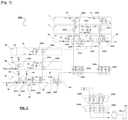
- the figure 1 shows an example of a control unit 1000 of at least one motor for operating a cut-off switch which comprises a sequential relay logic for controlling the operation of said motor.
- the principle employed applies in a similar way to the motor for controlling circuit breakers or switches.
- the principle of the sequential logic as described for a switch comprises a cascade of signal switching relays provided with a first stage 1 comprising a first closing operation prohibition relay of said switching device when a priority opening command is issued.
- This first stage comprises a first coil 100A, the power supply of which cuts the circuit 100B of said first relay upon detection of an opening maneuver command from said switching device.
- a second stage 2 will prohibit operation of the motor if the unit receives a power use signal from another unit.
- This second stage is provided with at least a second motor inhibition relay 101B, 101C provided with a second coil 101A supplied by an input 21 receiving the operating signal from a motor external to the unit.
- the unit further comprises a third motor operation validation stage 3A, 3B provided with relays 102B, 102C, 103B, 103C and signal inputs for the opening limit switch 31 and the closing limit switch 32 to stop the motor when he comes to the end of the race.
- a third motor operation validation stage 3A, 3B provided with relays 102B, 102C, 103B, 103C and signal inputs for the opening limit switch 31 and the closing limit switch 32 to stop the motor when he comes to the end of the race.
- the unit further comprises, according to the example, at least a fourth stage 4A, 4B provided with one or more fourth relays for inhibiting operation upon detection of conditions for inhibiting engine operation such as a medium voltage switch to earth or other.
- the control unit comprises at least one power relay for supplying current to the motor in the closing direction of the switch here produced by the double relay 200B and at least one power relay for the current supply to the motor in the opening direction of the switch here carried out by the double relay 202B.
- the unit comprises relays 200B, 201B in series for opening and relays 202B, 203B in series for closing the switch to reduce the arcs when starting and stopping the motors.
- These relays receive power supplies DB+ and DB- and control the motor supply voltages M+, M- for supplying the motor 740 for controlling the switching device 741.
- the unit finally comprises a motor priority management stage 4C, 4D seen below.
- the present description proposes a motor operating priority management device provided with a first line 1010 and a second line 1020.
- the first line 1010 is shown in picture 2 .
- This line is the carrier of binary data comprising a first state representative of the stoppage of all the motors and a second state representative of the operation of any one of the motors.
- the first state is an “in the air” state and the second state is the zeroing of the line, an inverted logic remaining of course possible.
- support of binary data it is understood that a line is configured to transmit this binary data.
- second state representative of the operation of any of the motors it is understood that any of the motors is in operation, in particular following receipt of a start command.
- the units of the substation 1001, 1002, 1003, 1004, 1005, ... are connected in parallel on the line 1010, said parallel line being connected to a motor start inhibiting device of each unit comprising the relays 106B of the priority management stage 4D of each of the units, or according to the example, the relays 106B1 to 106B5.
- These relays make it possible to reset the line during a command to start the motor of a unit.
- This circuit is found in figure 1 under the reference 106B and the control coil 106A of the relay 106B will be active during the command to start the motor of the unit when the control signal is validated at the level of the relay 105A.
- This line is furthermore connected to a circuit for authorizing/inhibiting the operation of the motor of the units through a relay 105C1 represented only for the unit 1001 to avoid overloading the diagram.
- This relay is found in figure 1 under the reference 105C and is controlled by a coil 105A which will pass the signal PWU 45 in PWU_V1 46 to prohibit the starting sequence of the motor of the unit when the motor of another unit is running while the coil 105A will cut the link between the PWU signal and the PWU_V1 signal when the unit motor starts.
- the second line 1020 is a line inhibiting operation of motors downstream of said any one of said motors upon detection of a start signal from said any one of said motors.
- the serial line has an upstream end 1020a set to zero and passes through a cutoff relay 107B of each unit from the upstream unit 1001 to the downstream units 1002, 1003, ....
- the control coil 107A of the cut-off relay 107B has its hot point connected to the motor control of the corresponding unit and its cold point connected to the serial line through an anti-return diode D3.
- each unit comprises a logic device or control stage 106A, 106B for setting the first line parallel to the second state representative of the operation of its motor in response to the operation of the motor of this unit, said second state activating the devices of prohibit engine start-up of other units.
- the control stage 106A constitutes a motor operation authorization stage on the presence of an upstream link 43 on the serial line.
- the engine start-up command closes a relay 106C which enables the power supply to the cold point of coils 200A, 201A, 202A, 203A of the engine control power relay and closes a relay 106B to zero of the parallel line PWU 1010 on terminal 47 when operation of the engine of said unit to transmit this information to the other units.
- relay 106A cannot be energized, which leaves relay 106B open and prevents relay 106C from being energized, thus preventing motor starting.
- the command 107A opens for its part the serial link downstream SYNR 44 at the level of the relay 107B during the engine operation of the unit.
- the units further comprise means for releasing the parallel line upon stopping of said motor through relay 105B which, by cutting off the arrival of the hot point of coil 106A when the motor stops (for example in the case of the activation of a limit switch 31 or 32) opens the relay 106B.
- the parallel line PWU returns to high impedance at the level of relay 106B and the downstream line SYNR is reconnected to the upstream line SYNL at the level of relay 107B while the MEM_DI signal is deactivated and the control of the relays of power is re-opened at relay 106C.
- the upstream serial line SYNL entering the unit at the level of the upstream connection 43 and the downstream serial line SYNR leaving the unit at the level of the connection 44 therefore allows prioritization of motor operation from upstream to downstream.
- the upstream unit would obtain the power and the power of the downstream unit would be disconnected.
- PWU is used to inform the units that the motor power of a unit is used, which makes it possible to ignore the start-up commands from the other units.
- serial link is connected to 0V when motor operation is enabled and at high impedance otherwise. It is however conceivable to carry out an assembly where the operating signal of an upstream unit would be at a voltage different from zero.
- the parallel line PWU is connected to 0 volts if one of the motors is used and is high impedance if no motor is used.
- Other configurations remain possible within the scope of the invention.
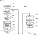
- the figure 4 gives a representation in flowchart form of an operating sequence of programmed or hard-wired logic applicable to the invention.
- the hard-wired logic of the example of the figure 1 can be replaced by an electronic card such as a microprocessor or microcontroller card provided with inputs for sensors such as business switches such as interlocks which inhibit motor starting in the event of abnormal conditions such as opening of the casing , earthing of the medium voltage switch, inputs for motor limit switches, inputs/outputs for managing parallel 1010 and series 1020 lines and control outputs for power relays 200, 201, 202, 203 engines.
- an electronic card such as a microprocessor or microcontroller card provided with inputs for sensors such as business switches such as interlocks which inhibit motor starting in the event of abnormal conditions such as opening of the casing , earthing of the medium voltage switch, inputs for motor limit switches, inputs/outputs for managing parallel 1010 and series 1020 lines and control outputs for power relays 200, 201, 202, 203 engines.
- the microprocessor or microcontroller comprises motor control software which will carry out the sequences necessary for operating the motors and positioning the serial and parallel lines in the desired states according to the example of simplified sequential logic 500 of the figure 4 which also happens to be applicable to the cable system of figures 1 to 3 .
- the figure 4 represents in this context an operating sequence initiated by a motor activation command 510. Once the command has been received, a sequence of tests is initiated.
- the unit concerned sets the motor signal of the parallel link 1010 to the state used in step 550, de-validates the synchro signal of the serial link 1020 for the downstream units at step 560, starts the motor at step 570 and then tests if the command is complete at step 580.
- the software triggers the stopping of the motor at step 590, resets the PWM signal of the parallel line 0 to the free state at step 600, revalidates the synchro signal for the downstream units at step 610 then the sequence ends at the end step 620b to return to waiting for an activation command.
- part of the loop is again executed to test whether a fault appears, in particular so that the process can be interrupted by stopping the motor.
- a controller device 700 with microprocessor or microcontroller is schematized in figure 5 with at 710 the interlocks connected to inputs of the controller, the parallel link and the serial link connected to inputs of the controller through isolation components 1021, 1061, the parallel link connected to an output of the controller through a first relay or analog switch 1060, the serial link 1020 connected to an output of the controller through a second relay or transistor, the motor start control signal at input 711 of the controller and outputs 712, 713 driving relays 720, 730 similar to relays 200, ..., 203 of the figure 1 to drive the 740 motor.
- the invention is not limited to the examples described above.
- the principle of the invention for which two wired lines connect motor control units with sequential logic can be applied to systems for which the sequential logic is carried out with a digital card with microprocessor, microcontroller or programmable logic instead of relay.
Landscapes
- Engineering & Computer Science (AREA)
- Power Engineering (AREA)
- Business, Economics & Management (AREA)
- Physics & Mathematics (AREA)
- Chemical & Material Sciences (AREA)
- Combustion & Propulsion (AREA)
- Mechanical Engineering (AREA)
- General Engineering & Computer Science (AREA)
- Health & Medical Sciences (AREA)
- Economics (AREA)
- General Physics & Mathematics (AREA)
- Water Supply & Treatment (AREA)
- Human Resources & Organizations (AREA)
- Marketing (AREA)
- Primary Health Care (AREA)
- Strategic Management (AREA)
- Tourism & Hospitality (AREA)
- General Health & Medical Sciences (AREA)
- General Business, Economics & Management (AREA)
- Public Health (AREA)
- Theoretical Computer Science (AREA)
- Automation & Control Theory (AREA)
- Control Of Multiple Motors (AREA)
Applications Claiming Priority (1)
| Application Number | Priority Date | Filing Date | Title |
|---|---|---|---|
| FR2009083A FR3113960B1 (fr) | 2020-09-08 | 2020-09-08 | Interface de pilotage de disjoncteurs et interrupteurs moyenne tension |
Publications (1)
| Publication Number | Publication Date |
|---|---|
| EP3964901A1 true EP3964901A1 (de) | 2022-03-09 |
Family
ID=73793354
Family Applications (1)
| Application Number | Title | Priority Date | Filing Date |
|---|---|---|---|
| EP21193792.5A Pending EP3964901A1 (de) | 2020-09-08 | 2021-08-30 | Steuerschnittstelle für mittelspannungsschutz- und trennschalter |
Country Status (4)
| Country | Link |
|---|---|
| US (1) | US11936322B2 (de) |
| EP (1) | EP3964901A1 (de) |
| CN (1) | CN114157182A (de) |
| FR (1) | FR3113960B1 (de) |
Citations (4)
| Publication number | Priority date | Publication date | Assignee | Title |
|---|---|---|---|---|
| DE3823574C1 (en) * | 1988-07-12 | 1989-11-16 | Sachsenwerk Ag, 8400 Regensburg, De | Drive for a transmission with a motor having a reversible rotation direction |
| WO2011147928A1 (fr) * | 2010-05-28 | 2011-12-01 | Alstom Grid Sas | Dispositif de commande d'une pluralite d'appareils de coupure de courant via des moteurs electriques |
| EP2797219A2 (de) * | 2013-04-22 | 2014-10-29 | Rockwell Automation Technologies, Inc. | Selbstgeschützte dynamische Bremsung |
| WO2020109285A1 (de) * | 2018-11-26 | 2020-06-04 | Phoenix Contact Gmbh & Co.Kg | Modulare schaltvorrichtung zum ansteuern wenigstens eines elektrischen antriebs |
-
2020
- 2020-09-08 FR FR2009083A patent/FR3113960B1/fr active Active
-
2021
- 2021-08-30 EP EP21193792.5A patent/EP3964901A1/de active Pending
- 2021-09-07 US US17/467,537 patent/US11936322B2/en active Active
- 2021-09-08 CN CN202111048397.8A patent/CN114157182A/zh active Pending
Patent Citations (4)
| Publication number | Priority date | Publication date | Assignee | Title |
|---|---|---|---|---|
| DE3823574C1 (en) * | 1988-07-12 | 1989-11-16 | Sachsenwerk Ag, 8400 Regensburg, De | Drive for a transmission with a motor having a reversible rotation direction |
| WO2011147928A1 (fr) * | 2010-05-28 | 2011-12-01 | Alstom Grid Sas | Dispositif de commande d'une pluralite d'appareils de coupure de courant via des moteurs electriques |
| EP2797219A2 (de) * | 2013-04-22 | 2014-10-29 | Rockwell Automation Technologies, Inc. | Selbstgeschützte dynamische Bremsung |
| WO2020109285A1 (de) * | 2018-11-26 | 2020-06-04 | Phoenix Contact Gmbh & Co.Kg | Modulare schaltvorrichtung zum ansteuern wenigstens eines elektrischen antriebs |
Also Published As
| Publication number | Publication date |
|---|---|
| FR3113960A1 (fr) | 2022-03-11 |
| FR3113960B1 (fr) | 2022-09-16 |
| US20220094283A1 (en) | 2022-03-24 |
| US11936322B2 (en) | 2024-03-19 |
| CN114157182A (zh) | 2022-03-08 |
Similar Documents
| Publication | Publication Date | Title |
|---|---|---|
| EP3276769A1 (de) | Gerät zur überwachung/steuerung eines schalters für quellen | |
| FR2908939A1 (fr) | Dispositif de commande pour assurer la regulation en tension d'un bus d'alimentation. | |
| EP3964901A1 (de) | Steuerschnittstelle für mittelspannungsschutz- und trennschalter | |
| EP2864201B1 (de) | Elektrische schaltung zum abschalten einer elektrischen stromversorgung mit transistoren und schmelzsicherungen mit redundanter logik | |
| FR2815789A1 (fr) | Dispositif d'alimentation electrique a haut niveau de securite | |
| EP3146613B1 (de) | System aus batterien und verfahren zur steuerung dieses systems | |
| CA2364846C (fr) | Systeme de distribution d'energie electrique et contacteur pour un tel systeme | |
| CA1205893A (fr) | Interface pour relier un systeme informatique a un dispositif actionneur | |
| EP3179597B1 (de) | Verbesserte vorrichtung zur lieferung von einphasen- und dreiphasen-strom | |
| EP3008745B1 (de) | Unterstützungsvorrichtung und -verfahren für ein energieerzeugungssystem eines flugzeugs | |
| FR3024600A1 (fr) | Systeme de mise en securite pour le raccordement electrique d'un equipement electrique a un appareil d'alimentation electrique, et installation electrique comprenant un tel systeme | |
| EP2515409B1 (de) | Verfahren zur Konfiguration einer elektrischen Energieumwandlungsanlage, und Anlage zur Umsetzung dieses Verfahrens | |
| EP2999084B1 (de) | Elektrische verbindungsvorrichtung für stromquellen-umschalter, und stromquellen-umschalter, der eine solche vorrichtung umfasst | |
| EP3877774B1 (de) | Vorrichtung zur unterdrückung der stromabgabe aus einer vorrichtung mit schaltelementen für überwachte leckage | |
| EP3900175B1 (de) | System zur steuerung eines spannungswandlers | |
| EP3273258B1 (de) | Verfahren zur steuerung einer elektrischen anlage von einem entfernten ort aus | |
| FR3084973A1 (fr) | Procede de transfert sans recouvrement de sources d'energie electrique et inverseur de source mettant en oeuvre un tel procede | |
| FR3092211A1 (fr) | Système électrique pour véhicule et procédé de commande d’un tel système | |
| WO2020260042A1 (fr) | Coupe-circuit hybride a fonctionnement sequentiel | |
| EP2738900A1 (de) | Kontinuierliches Stromeinspeisungssystem von mindestens zwei Ladungen von einer alternativen Stromquelle aus, und Verfahren zum Starten eines solchen Einspeisungssystems | |
| BE898689A (fr) | Procede et appareil de blocage automatique d'un interrupteur de deconnexion de charge a proximite d'un defaut localise | |
| EP3689663A1 (de) | Sicherungsverfahren von segmenten eines stromversorgungssystems über den boden, und entsprechendes system | |
| FR2706094A1 (fr) | Dispositif de commande d'un mécanisme entrainé par ua moins un moteur électrique. | |
| FR2511204A1 (fr) | Dispositif de protection differentielle contre les courts-circuits entre les phases d'un moteur electrique | |
| FR2835805A1 (fr) | Dispositif pour satellite comportant des moyens d'alimentation en puissance et associe a des moyens de chauffage |
Legal Events
| Date | Code | Title | Description |
|---|---|---|---|
| PUAI | Public reference made under article 153(3) epc to a published international application that has entered the european phase |
Free format text: ORIGINAL CODE: 0009012 |
|
| STAA | Information on the status of an ep patent application or granted ep patent |
Free format text: STATUS: THE APPLICATION HAS BEEN PUBLISHED |
|
| AK | Designated contracting states |
Kind code of ref document: A1 Designated state(s): AL AT BE BG CH CY CZ DE DK EE ES FI FR GB GR HR HU IE IS IT LI LT LU LV MC MK MT NL NO PL PT RO RS SE SI SK SM TR |
|
| STAA | Information on the status of an ep patent application or granted ep patent |
Free format text: STATUS: REQUEST FOR EXAMINATION WAS MADE |
|
| 17P | Request for examination filed |
Effective date: 20220729 |
|
| RBV | Designated contracting states (corrected) |
Designated state(s): AL AT BE BG CH CY CZ DE DK EE ES FI FR GB GR HR HU IE IS IT LI LT LU LV MC MK MT NL NO PL PT RO RS SE SI SK SM TR |
|
| STAA | Information on the status of an ep patent application or granted ep patent |
Free format text: STATUS: EXAMINATION IS IN PROGRESS |
|
| 17Q | First examination report despatched |
Effective date: 20230413 |
|
| GRAP | Despatch of communication of intention to grant a patent |
Free format text: ORIGINAL CODE: EPIDOSNIGR1 |
|
| STAA | Information on the status of an ep patent application or granted ep patent |
Free format text: STATUS: GRANT OF PATENT IS INTENDED |
|
| RIC1 | Information provided on ipc code assigned before grant |
Ipc: G05B 9/02 20060101ALN20240417BHEP Ipc: H02H 7/08 20060101ALI20240417BHEP Ipc: H01H 33/36 20060101ALI20240417BHEP Ipc: H01H 71/00 20060101ALI20240417BHEP Ipc: F02N 11/08 20060101ALI20240417BHEP Ipc: G06Q 50/06 20120101ALI20240417BHEP Ipc: G05B 19/05 20060101AFI20240417BHEP |
|
| INTG | Intention to grant announced |
Effective date: 20240507 |