EP3608892A1 - System und verfahren zur aufrechterhaltung der standortinformationen von verkehrsvorrichtungen - Google Patents
System und verfahren zur aufrechterhaltung der standortinformationen von verkehrsvorrichtungen Download PDFInfo
- Publication number
- EP3608892A1 EP3608892A1 EP19191090.0A EP19191090A EP3608892A1 EP 3608892 A1 EP3608892 A1 EP 3608892A1 EP 19191090 A EP19191090 A EP 19191090A EP 3608892 A1 EP3608892 A1 EP 3608892A1
- Authority
- EP
- European Patent Office
- Prior art keywords
- data
- traffic
- remote device
- location
- beacon
- Prior art date
- Legal status (The legal status is an assumption and is not a legal conclusion. Google has not performed a legal analysis and makes no representation as to the accuracy of the status listed.)
- Granted
Links
Images

Classifications
-
- G—PHYSICS
- G08—SIGNALLING
- G08G—TRAFFIC CONTROL SYSTEMS
- G08G1/00—Traffic control systems for road vehicles
- G08G1/09—Arrangements for giving variable traffic instructions
- G08G1/095—Traffic lights
- G08G1/0955—Traffic lights transportable
-
- G—PHYSICS
- G08—SIGNALLING
- G08G—TRAFFIC CONTROL SYSTEMS
- G08G1/00—Traffic control systems for road vehicles
- G08G1/097—Supervising of traffic control systems, e.g. by giving an alarm if two crossing streets have green light simultaneously
-
- B—PERFORMING OPERATIONS; TRANSPORTING
- B60—VEHICLES IN GENERAL
- B60W—CONJOINT CONTROL OF VEHICLE SUB-UNITS OF DIFFERENT TYPE OR DIFFERENT FUNCTION; CONTROL SYSTEMS SPECIALLY ADAPTED FOR HYBRID VEHICLES; ROAD VEHICLE DRIVE CONTROL SYSTEMS FOR PURPOSES NOT RELATED TO THE CONTROL OF A PARTICULAR SUB-UNIT
- B60W40/00—Estimation or calculation of non-directly measurable driving parameters for road vehicle drive control systems not related to the control of a particular sub unit, e.g. by using mathematical models
- B60W40/02—Estimation or calculation of non-directly measurable driving parameters for road vehicle drive control systems not related to the control of a particular sub unit, e.g. by using mathematical models related to ambient conditions
- B60W40/04—Traffic conditions
-
- E—FIXED CONSTRUCTIONS
- E01—CONSTRUCTION OF ROADS, RAILWAYS, OR BRIDGES
- E01F—ADDITIONAL WORK, SUCH AS EQUIPPING ROADS OR THE CONSTRUCTION OF PLATFORMS, HELICOPTER LANDING STAGES, SIGNS, SNOW FENCES, OR THE LIKE
- E01F9/00—Arrangement of road signs or traffic signals; Arrangements for enforcing caution
- E01F9/30—Arrangements interacting with transmitters or receivers otherwise than by visible means, e.g. using radar reflectors or radio transmitters
-
- G—PHYSICS
- G01—MEASURING; TESTING
- G01S—RADIO DIRECTION-FINDING; RADIO NAVIGATION; DETERMINING DISTANCE OR VELOCITY BY USE OF RADIO WAVES; LOCATING OR PRESENCE-DETECTING BY USE OF THE REFLECTION OR RERADIATION OF RADIO WAVES; ANALOGOUS ARRANGEMENTS USING OTHER WAVES
- G01S1/00—Beacons or beacon systems transmitting signals having a characteristic or characteristics capable of being detected by non-directional receivers and defining directions, positions, or position lines fixed relatively to the beacon transmitters; Receivers co-operating therewith
- G01S1/02—Beacons or beacon systems transmitting signals having a characteristic or characteristics capable of being detected by non-directional receivers and defining directions, positions, or position lines fixed relatively to the beacon transmitters; Receivers co-operating therewith using radio waves
- G01S1/04—Details
- G01S1/042—Transmitters
- G01S1/0423—Mounting or deployment thereof
-
- G—PHYSICS
- G01—MEASURING; TESTING
- G01S—RADIO DIRECTION-FINDING; RADIO NAVIGATION; DETERMINING DISTANCE OR VELOCITY BY USE OF RADIO WAVES; LOCATING OR PRESENCE-DETECTING BY USE OF THE REFLECTION OR RERADIATION OF RADIO WAVES; ANALOGOUS ARRANGEMENTS USING OTHER WAVES
- G01S1/00—Beacons or beacon systems transmitting signals having a characteristic or characteristics capable of being detected by non-directional receivers and defining directions, positions, or position lines fixed relatively to the beacon transmitters; Receivers co-operating therewith
- G01S1/02—Beacons or beacon systems transmitting signals having a characteristic or characteristics capable of being detected by non-directional receivers and defining directions, positions, or position lines fixed relatively to the beacon transmitters; Receivers co-operating therewith using radio waves
- G01S1/68—Marker, boundary, call-sign, or like beacons transmitting signals not carrying directional information
-
- G—PHYSICS
- G01—MEASURING; TESTING
- G01S—RADIO DIRECTION-FINDING; RADIO NAVIGATION; DETERMINING DISTANCE OR VELOCITY BY USE OF RADIO WAVES; LOCATING OR PRESENCE-DETECTING BY USE OF THE REFLECTION OR RERADIATION OF RADIO WAVES; ANALOGOUS ARRANGEMENTS USING OTHER WAVES
- G01S11/00—Systems for determining distance or velocity not using reflection or reradiation
- G01S11/02—Systems for determining distance or velocity not using reflection or reradiation using radio waves
- G01S11/06—Systems for determining distance or velocity not using reflection or reradiation using radio waves using intensity measurements
-
- G—PHYSICS
- G01—MEASURING; TESTING
- G01S—RADIO DIRECTION-FINDING; RADIO NAVIGATION; DETERMINING DISTANCE OR VELOCITY BY USE OF RADIO WAVES; LOCATING OR PRESENCE-DETECTING BY USE OF THE REFLECTION OR RERADIATION OF RADIO WAVES; ANALOGOUS ARRANGEMENTS USING OTHER WAVES
- G01S5/00—Position-fixing by co-ordinating two or more direction or position line determinations; Position-fixing by co-ordinating two or more distance determinations
- G01S5/0009—Transmission of position information to remote stations
- G01S5/0018—Transmission from mobile station to base station
- G01S5/0027—Transmission from mobile station to base station of actual mobile position, i.e. position determined on mobile
-
- G—PHYSICS
- G01—MEASURING; TESTING
- G01S—RADIO DIRECTION-FINDING; RADIO NAVIGATION; DETERMINING DISTANCE OR VELOCITY BY USE OF RADIO WAVES; LOCATING OR PRESENCE-DETECTING BY USE OF THE REFLECTION OR RERADIATION OF RADIO WAVES; ANALOGOUS ARRANGEMENTS USING OTHER WAVES
- G01S5/00—Position-fixing by co-ordinating two or more direction or position line determinations; Position-fixing by co-ordinating two or more distance determinations
- G01S5/02—Position-fixing by co-ordinating two or more direction or position line determinations; Position-fixing by co-ordinating two or more distance determinations using radio waves
- G01S5/0284—Relative positioning
-
- G—PHYSICS
- G01—MEASURING; TESTING
- G01S—RADIO DIRECTION-FINDING; RADIO NAVIGATION; DETERMINING DISTANCE OR VELOCITY BY USE OF RADIO WAVES; LOCATING OR PRESENCE-DETECTING BY USE OF THE REFLECTION OR RERADIATION OF RADIO WAVES; ANALOGOUS ARRANGEMENTS USING OTHER WAVES
- G01S5/00—Position-fixing by co-ordinating two or more direction or position line determinations; Position-fixing by co-ordinating two or more distance determinations
- G01S5/02—Position-fixing by co-ordinating two or more direction or position line determinations; Position-fixing by co-ordinating two or more distance determinations using radio waves
- G01S5/0295—Proximity-based methods, e.g. position inferred from reception of particular signals
-
- G—PHYSICS
- G06—COMPUTING OR CALCULATING; COUNTING
- G06F—ELECTRIC DIGITAL DATA PROCESSING
- G06F16/00—Information retrieval; Database structures therefor; File system structures therefor
- G06F16/20—Information retrieval; Database structures therefor; File system structures therefor of structured data, e.g. relational data
- G06F16/29—Geographical information databases
-
- G—PHYSICS
- G08—SIGNALLING
- G08G—TRAFFIC CONTROL SYSTEMS
- G08G1/00—Traffic control systems for road vehicles
- G08G1/01—Detecting movement of traffic to be counted or controlled
- G08G1/0104—Measuring and analyzing of parameters relative to traffic conditions
- G08G1/0137—Measuring and analyzing of parameters relative to traffic conditions for specific applications
- G08G1/0145—Measuring and analyzing of parameters relative to traffic conditions for specific applications for active traffic flow control
-
- G—PHYSICS
- G08—SIGNALLING
- G08G—TRAFFIC CONTROL SYSTEMS
- G08G1/00—Traffic control systems for road vehicles
- G08G1/09—Arrangements for giving variable traffic instructions
- G08G1/0962—Arrangements for giving variable traffic instructions having an indicator mounted inside the vehicle, e.g. giving voice messages
- G08G1/0967—Systems involving transmission of highway information, e.g. weather, speed limits
- G08G1/096766—Systems involving transmission of highway information, e.g. weather, speed limits where the system is characterised by the origin of the information transmission
- G08G1/096783—Systems involving transmission of highway information, e.g. weather, speed limits where the system is characterised by the origin of the information transmission where the origin of the information is a roadside individual element
-
- H—ELECTRICITY
- H04—ELECTRIC COMMUNICATION TECHNIQUE
- H04W—WIRELESS COMMUNICATION NETWORKS
- H04W4/00—Services specially adapted for wireless communication networks; Facilities therefor
- H04W4/02—Services making use of location information
- H04W4/025—Services making use of location information using location based information parameters
-
- H—ELECTRICITY
- H04—ELECTRIC COMMUNICATION TECHNIQUE
- H04W—WIRELESS COMMUNICATION NETWORKS
- H04W4/00—Services specially adapted for wireless communication networks; Facilities therefor
- H04W4/30—Services specially adapted for particular environments, situations or purposes
- H04W4/40—Services specially adapted for particular environments, situations or purposes for vehicles, e.g. vehicle-to-pedestrians [V2P]
-
- H—ELECTRICITY
- H04—ELECTRIC COMMUNICATION TECHNIQUE
- H04W—WIRELESS COMMUNICATION NETWORKS
- H04W64/00—Locating users or terminals or network equipment for network management purposes, e.g. mobility management
-
- H—ELECTRICITY
- H04—ELECTRIC COMMUNICATION TECHNIQUE
- H04W—WIRELESS COMMUNICATION NETWORKS
- H04W64/00—Locating users or terminals or network equipment for network management purposes, e.g. mobility management
- H04W64/003—Locating users or terminals or network equipment for network management purposes, e.g. mobility management locating network equipment
-
- H—ELECTRICITY
- H04—ELECTRIC COMMUNICATION TECHNIQUE
- H04W—WIRELESS COMMUNICATION NETWORKS
- H04W76/00—Connection management
- H04W76/40—Connection management for selective distribution or broadcast
-
- A—HUMAN NECESSITIES
- A41—WEARING APPAREL
- A41D—OUTERWEAR; PROTECTIVE GARMENTS; ACCESSORIES
- A41D2600/00—Uses of garments specially adapted for specific purposes
- A41D2600/20—Uses of garments specially adapted for specific purposes for working activities
-
- G—PHYSICS
- G01—MEASURING; TESTING
- G01S—RADIO DIRECTION-FINDING; RADIO NAVIGATION; DETERMINING DISTANCE OR VELOCITY BY USE OF RADIO WAVES; LOCATING OR PRESENCE-DETECTING BY USE OF THE REFLECTION OR RERADIATION OF RADIO WAVES; ANALOGOUS ARRANGEMENTS USING OTHER WAVES
- G01S2201/00—Indexing scheme relating to beacons or beacon systems transmitting signals capable of being detected by non-directional receivers and defining directions, positions, or position lines fixed relatively to the beacon transmitters
- G01S2201/01—Indexing scheme relating to beacons or beacon systems transmitting signals capable of being detected by non-directional receivers and defining directions, positions, or position lines fixed relatively to the beacon transmitters adapted for specific applications or environments
-
- G—PHYSICS
- G01—MEASURING; TESTING
- G01S—RADIO DIRECTION-FINDING; RADIO NAVIGATION; DETERMINING DISTANCE OR VELOCITY BY USE OF RADIO WAVES; LOCATING OR PRESENCE-DETECTING BY USE OF THE REFLECTION OR RERADIATION OF RADIO WAVES; ANALOGOUS ARRANGEMENTS USING OTHER WAVES
- G01S2205/00—Position-fixing by co-ordinating two or more direction or position line determinations; Position-fixing by co-ordinating two or more distance determinations
- G01S2205/01—Position-fixing by co-ordinating two or more direction or position line determinations; Position-fixing by co-ordinating two or more distance determinations specially adapted for specific applications
-
- G—PHYSICS
- G08—SIGNALLING
- G08G—TRAFFIC CONTROL SYSTEMS
- G08G1/00—Traffic control systems for road vehicles
- G08G1/01—Detecting movement of traffic to be counted or controlled
- G08G1/0104—Measuring and analyzing of parameters relative to traffic conditions
- G08G1/0108—Measuring and analyzing of parameters relative to traffic conditions based on the source of data
- G08G1/0116—Measuring and analyzing of parameters relative to traffic conditions based on the source of data from roadside infrastructure, e.g. beacons
-
- G—PHYSICS
- G08—SIGNALLING
- G08G—TRAFFIC CONTROL SYSTEMS
- G08G1/00—Traffic control systems for road vehicles
- G08G1/01—Detecting movement of traffic to be counted or controlled
- G08G1/0104—Measuring and analyzing of parameters relative to traffic conditions
- G08G1/0125—Traffic data processing
- G08G1/0133—Traffic data processing for classifying traffic situation
-
- G—PHYSICS
- G08—SIGNALLING
- G08G—TRAFFIC CONTROL SYSTEMS
- G08G1/00—Traffic control systems for road vehicles
- G08G1/01—Detecting movement of traffic to be counted or controlled
- G08G1/0104—Measuring and analyzing of parameters relative to traffic conditions
- G08G1/0137—Measuring and analyzing of parameters relative to traffic conditions for specific applications
- G08G1/0141—Measuring and analyzing of parameters relative to traffic conditions for specific applications for traffic information dissemination
-
- H—ELECTRICITY
- H04—ELECTRIC COMMUNICATION TECHNIQUE
- H04W—WIRELESS COMMUNICATION NETWORKS
- H04W4/00—Services specially adapted for wireless communication networks; Facilities therefor
- H04W4/80—Services using short range communication, e.g. near-field communication [NFC], radio-frequency identification [RFID] or low energy communication
Definitions
- aspects of the disclosed subject matter relate generally to road-side traffic apparatus, and more particularly to a system and method of acquiring and maintaining location information associated with such apparatus deployed in connection with a traffic flow monitoring or regulation system.
- Traffic flow information and pattern regulation are useful tools for informing motorists of congestion, hazards, accidents, police or highway safety personnel activity, and the like.
- Some traffic flow and pattern control apparatus may be deployed in construction zones, for example, or in areas such as freeway interchanges or toll plazas where traffic congestion is regular or frequent, or in areas requiring temporary rerouting of vehicular traffic.
- many such traffic flow and pattern control apparatus are designed to be portable, or at least moveable (i.e., they may not be permanently affixed to or integrated into the roadway or other immovable infrastructure).
- traffic monitoring systems acquire and transmit traffic flow data to a remote system which processes data for use in connection with one or more applications.
- a typical traffic flow monitoring and regulation system may, for example, update road-side or overhead signage with information concerning traffic patterns that a motorist may expect to encounter some distance ahead.
- traffic data may be provided to third party mapping and navigation tools, providing a user of such a tool with real-time or near real-time information concerning traffic conditions where they are being monitored. In connection with these and other systems, it may be useful to identify the location of each traffic flow and pattern control apparatus placed on or near the route being monitored or controlled.
- a portable traffic apparatus be light-weight but sturdy, easily moveable to a suitable location, visible to motorists to prevent damage or destruction, and self-powered, since a portable device may not always be positioned such that it may readily be wired to electric utility services. Portability may be desirable for many applications, as investment in a permanent physical infrastructure is not required and because a traffic apparatus may quickly and selectively be deployed only where it is needed. As noted above, however, portable structures may be moved, and so it may be useful in many applications to acquire and to maintain accurate location information for each such apparatus that is deployed.
- the present disclosure describes a system and method of acquiring and maintaining location information associated with traffic flow and pattern control apparatus used in connection with a traffic flow monitoring or regulation system.
- the purpose and location of each such apparatus deployed in a traffic pattern control application may be acquired and maintained, for example, to monitor, verify, or modify a traffic flow control strategy.
- a beacon or transceiver may transmit a signal indicative of a functionality associated with an apparatus, and the location of the beacon may be acquired or recorded; in the foregoing manner, a map or other record of apparatus purposes and locations in space may be accurately maintained.
- cellular signals, global positioning system (GPS) implementations, or other positioning sensors may be employed either individually or in combination with navigational aids or other mapping applications to identify a particular location of a particular apparatus along a roadway to be monitored or controlled.
- GPS global positioning system
- a method of acquiring and maintaining location information associated with a traffic apparatus may generally comprise: affixing a beacon system to the traffic apparatus, the beacon system operative to broadcast apparatus data associated with the traffic apparatus to a remote device; capturing the apparatus data responsive to a measure of a signal strength of the beacon system; deriving location data associated with the traffic apparatus responsive to said capturing; and recording a location of the traffic apparatus in space based upon the deriving.
- the beacon system is operative to broadcast the apparatus data periodically at a frequency.
- the capturing is responsive to a peak signal strength.
- the deriving comprises utilizing the apparatus data.
- the beacon system is operative to broadcast the apparatus data responsive to a proximity of the remote device.
- the deriving comprises utilizing positioning data resident on the remote device.
- the apparatus data may include a unique apparatus identifier, a functional identifier associated with a function of the traffic apparatus, or both.
- the method may optionally further comprise transmitting the apparatus data from the remote device to a computer processing system.
- the deriving may comprise utilizing the computer processing system.
- the recording may comprise utilizing the computer processing system.
- the method may optionally further comprise transmitting the location data from the computer processing system to a third party platform.
- a traffic apparatus location system may generally comprise: a traffic apparatus; a beacon system affixed to the traffic apparatus, the beacon system to broadcast apparatus data associated with the traffic apparatus; a remote device to receive the apparatus data broadcast by the beacon system; and a computer processing system to receive information associated with the apparatus data from the remote device; wherein the apparatus data are used to derive location data associated with a location of the traffic apparatus.
- the location data are included in the apparatus data broadcast by the beacon system.
- the beacon system may optionally be operative to broadcast the apparatus data periodically at a frequency.
- the beacon system may be operative to broadcast the apparatus data responsive to a proximity of the remote device.
- the location data may be derived based on a location of the remote device.
- the location data may be derived by the remote device, or the location data may be derived by the computer processing system.
- the apparatus data include a unique apparatus identifier, a functional identifier associated with a function of the traffic apparatus, or both.
- the remote device is a wireless telephone and in others, the remote device is a tablet computer.
- the beacon system comprises a wireless transceiver and is configured and operative to initiate the broadcast responsive to a signal from the remote device.
- the beacon system may optionally comprise one of a global positioning system sensor, a gyroscope, an altimeter, a compass, and an accelerometer.
- the computer processing system is operative to transmit the location data to a third party platform.
- a traffic apparatus may comprise: a structure to convey information to a motorist; and a beacon system affixed to said structure, said beacon system to broadcast apparatus data associated with said structure to a remote device configured and operative receive the apparatus data broadcast by said beacon system; wherein the remote device transmits information associated with the apparatus data to a computer processing system and the apparatus data are used to derive location data associated with a location of said structure.
- the structure comprises one of a drum, a delineator, a cone, a flasher, a fixed sign, a placard, a barricade, and a programmable sign.
- the structure may comprise one identified in the Manual on Uniform Traffic Control Devices.
- the beacon system may optionally comprise a memory to store the apparatus data.
- the memory may be selectively programmable, for instance.
- the apparatus data may be selectively programmed.
- the beacon system is operative to broadcast the apparatus data periodically at a frequency.
- the beacon system is operative to broadcast the apparatus data responsive to a proximity of the remote device.
- the apparatus data may include a unique apparatus identifier, a functional identifier associated with a function of the structure, or both.
- the functional identifier is selectively programmable.
- the beacon system may comprise a wireless transceiver and may be configured and operative to initiate the broadcast responsive to a signal from the remote device.
- the location data are derived by the beacon system.
- the beacon system may comprise one of a global positioning system sensor, a gyroscope, an altimeter, a compass, and an accelerometer.
- the structure is portable.
- a system and method of acquiring and maintaining traffic apparatus location information in connection with a traffic flow monitoring and regulation system may transmit information regarding the purpose and location of a traffic apparatus to a remote server or computer system.
- the present disclosure provides for a power efficient traffic apparatus data collecting system which acquires and maintains location and functionality data associated with traffic apparatus employed in the field, and transmits those data to a remote or distant computer server or computing platform such as, for instance, those associated with smart work or construction zones or other traffic management systems or platforms.
- a traffic flow data collection strategy such as described below may effectuate communications with a remote computer system via any of various wireless technologies such as wireless fidelity (WiFi) protocols, satellite or cellular communications standards, and the like.
- WiFi wireless fidelity
- the present disclosure is not intended to be limited by the nature or functional characteristics of the communications hardware or signaling methodologies used to enable the disclosed traffic apparatus to communicate apparatus data to a remote computer system, nor is it intended to be limited by the purpose or operation of the remote computer system itself.
- FIG. 1 illustrates a variety of traffic flow and pattern control apparatus to which the disclosed subject matter pertains
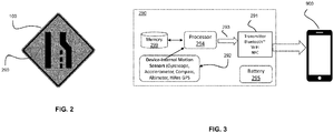
- FIG. 2 is an elevation view of a traffic flow and pattern control apparatus modified for use in connection with the disclosed subject matter.
- FIG. 1 depicts various types of traffic apparatus 100 that are familiar to most motorists: drums; delineators; cones; flashers; fixed signs or placards (such as "Road Work,” “Merge Left Ahead,” “Road Closed,” “Detour,” and “Traffic Signal Ahead” signs); and variable or selectively programmable lighted signs.
- traffic flow and pattern control apparatus and "traffic apparatus” are intended to encompass each of the traffic apparatus 100 illustrated in FIG. 1 as well as other signs, devices, structures, and informative instruments used to signal or to alert vehicular traffic to road conditions, speed limits or hazards, or to provide other information, as is generally known in the art. Examples of such traffic apparatus for use in Canada and the United States may be found, for example, in the Manual on Uniform Traffic Control Devices (the "MUTCD”) or in other analogous or counterpart publications in other jurisdictions.
- MUTCD Manual on Uniform Traffic Control Devices
- traffic apparatus 100 may be implemented as a barricade or other freestanding road-side structure that is light-weight, readily portable, and crash-certified.
- many governmental bodies or highway safety organizations require a safety or crash certification before a traffic apparatus 100 may be deployed road-side or near traffic patterns, even in emergency scenarios.
- design aspects of commercial embodiments of traffic apparatus 100 may be implemented as a function of local, state, or federal statutes or applicable regulations.
- the present disclosure is not intended to be limited to any particular implementation of the hardware components, materials, or communications protocols illustrated and described with reference to the drawing figures to the extent that any of these elements may be influenced or directed by statute or regulation or other design considerations.
- Traffic apparatus 100 in any of its various embodiments, may be constructed of a variety of materials generally known in the art having suitable strength, weight, weather durability, and ultraviolet (UV) light resistant characteristics. Examples include plastics, polyvinyl chloride (PVC), painted, coated, or weather-treated metals such as stainless steel, aluminum, and suitably weather-resistant alloys, ceramics, and other moldable or formable materials that have utility in outdoor and inclement weather applications.
- PVC polyvinyl chloride
- weather-treated metals such as stainless steel, aluminum, and suitably weather-resistant alloys, ceramics, and other moldable or formable materials that have utility in outdoor and inclement weather applications.
- the present disclosure is not intended to be limited by the materials or structural configuration of traffic apparatus 100, though an intended functionality of a particular traffic apparatus 100 may influence the instant system and method as set forth below.
- a signage embodiment of traffic apparatus 100 is depicted in FIG. 2 (i.e., "Merge Left").
- traffic apparatus 100 may generally include a beacon system 290, which may be mounted, affixed, or otherwise attached to or integrated into a structural element of traffic apparatus 100, which as noted above, may be embodied in or comprise a barrel or impact absorbing cylinder, a sign (as in FIG. 2 ), a cone, a barricade, a flasher, or other device.
- some powered components of traffic apparatus 100 may receive electrical power from a solar panel, a small windmill deployed on traffic apparatus 100 or proximate thereto, a battery source, or a combination of these and other power sources.
- beacon system 290 may be battery powered and so configured to conserve power as set forth in more detail below.
- FIG. 3 is a high-level functional schematic diagram of an embodiment of a beacon system to be used in connection with a traffic flow and pattern control apparatus.
- traffic apparatus 100 may generally comprise a beacon system 290 integrated with or attached to a suitable structural element as a function of the overall design and structural configuration of traffic apparatus 100.
- any of various mechanical fastening elements such as rivets, nuts and bolts, screws, clips or clamps, hook and loop fasteners, etc.
- adhesives, welding or brazing techniques, and other coupling techniques or structures may be employed to affix beacon system 290 to a structural element or portion of traffic apparatus 100.
- beacon system 290 generally comprises a wireless transmitter 291, such as a transmitter operative in accordance with BluetoothTM, WiFi, or a suitable near field communication (NFC) telecommunications standard.
- beacon system 290 via transmitter 291, may transmit certain information (such as GPS or other location data as well as identification data associated with the nature or operational characteristics of traffic apparatus 100) to a remote device (depicted in FIG. 3 as a wireless telephone identified by reference numeral 900).
- beacon system 290 may also comprise a memory 299 that may store data associated with the functionality or intended purpose of traffic apparatus 100.
- beacon system 290 may also include a wireless transceiver or suitable wired hardware interface (not shown), such as a universal serial bus (USB), DockPort jack, or other suitable data interface to allow data transfer to memory 299, enabling definition of the operability and functional characteristics of beacon system 290, and thereby, of traffic apparatus 100.
- a wireless transceiver or suitable wired hardware interface such as a universal serial bus (USB), DockPort jack, or other suitable data interface to allow data transfer to memory 299, enabling definition of the operability and functional characteristics of beacon system 290, and thereby, of traffic apparatus 100.
- memory 299 may maintain data associated with the specific traffic apparatus 100 ("apparatus data") to which beacon system 290 is affixed or attached.
- apparatus data may include a serial number, apparatus code, or other identifier that may have utility in enabling a system operator or administrator to identify or to distinguish a unique traffic apparatus 100 from a plurality of same that are deployed in a particular traffic control application.
- apparatus data may include a code, a series of bits or data words, or other indicator sufficient to identify the type or operational characteristics of traffic apparatus 100 in a particular application.
- such a code or identifier stored in memory 299 may identify the traffic apparatus 100 to which beacon system 290 is attached as a cone, a barrel, a barricade, or a sign ( FIG. 2 ); more particularly, such a code or identifier may further classify traffic apparatus 100 in accordance with the information, if any, provided to nearby motorists.
- apparatus data may be used to characterize a sign as conveying particular information, such as "10 MPH Zone,” “Merge Left Ahead” ( FIG. 2 ), “Yield,” “Detour Left,” and the like.
- each of the various traffic apparatus 100 illustrated in FIG. 1 may have a unique code or identifier to specify its function and to distinguish that function from others.
- another code or identifier may distinguish each individual traffic apparatus 100 from others having like functionality.
- memory 299 may be pre-coded for a particular purpose such that apparatus data for beacon system 290 is predetermined when memory 299 is initialized with data. In such situations, however, care must be taken by a system operator or administrator to ensure that a beacon system 290 pre-configured to operate in connection with a particular type of traffic apparatus 100 is properly affixed to a respective cone, barricade, sign, or placard, for instance, or the system in which that traffic apparatus 100 is deployed may record and maintain inaccurate data regarding the deployed arrangement of traffic apparatus 100.
- memory 299 may be selectively reprogrammed or rewritten such that beacon system 290 may be selectively programmable, for example, as a function of the type and nature of the traffic apparatus 100 to which it is affixed or attached.
- memory 299 may be programmed wirelessly, for example, or via a USB, DockPort, or other wired communication interface such that apparatus data stored in memory 299 accurately reflect the nature and operational characteristics of the traffic apparatus 100 to which beacon system 290 is affixed.
- memory 299 may be selectively programmed via a rocker panel, switch, or dial (not illustrated), for instance, such that beacon system 290 may be programmed to one of several functionalities in accordance with switch or dial position.
- placing a rocker panel or toggle switch in the left position may program memory 299 to characterize beacon system 290 as a "Merge Left” indicator, while placing the rocker panel or toggle switch in the right position may program memory 299 to characterize beacon system 290 as a "Merge Right” indicator.
- memory 299 may be programmed or selectively reprogrammed in any of various ways that are generally known in the art or developed in accordance with known principles and operational characteristics of memory 299, enabling flexibility and efficiency for traffic administrator work flow when employing beacon system 290 in connection with a desired type of traffic apparatus 100.
- memory 299 may be embodied in or comprise read only memory (ROM), electrically erasable programmable read-only memory (EEPROM) or other types of “flash” memory, any of various types of random access memory (RAM), or other solid-state memory device as a design choice, and generally selected as a function of power consumption, reliability, memory capacity, mean read/write cycles to failure, or a combination of these and other factors.
- ROM read only memory
- EEPROM electrically erasable programmable read-only memory
- flash any of various types of random access memory (RAM), or other solid-state memory device as a design choice, and generally selected as a function of power consumption, reliability, memory capacity, mean read/write cycles to failure, or a combination of these and other factors.
- RAM random access memory
- beacon system 290 may also comprise any of a number of different types of sensors 292.
- Sensors 292 may include gyroscopes, altimeters, compasses, accelerometers, GPS or other motion or positioning sensors, for example, having utility in locating and discovering the orientation of apparatus 100 in two- or three-dimensional space.
- it may be useful to communicate signals from sensors 292, via transmitter 291, to a remote system or processing platform such as device 900.
- data from sensors 292 may identify positioning, for instance, as well as acceleration or motion that may be indicative of a traffic apparatus 100 that has been moved since a previous data transmission. Comparison of successive compass data points, for example, may indicate expected, or unexpected (and therefore, undesirable), rotation of a traffic apparatus 100.
- data acquired by sensors 292 and data from memory 299 may be combined, concatenated, multiplexed, or otherwise aggregated for transmission by transmitter 291 (as indicated by aggregate data stream 293), though it may also be desirable that memory 299 or one or more sensors 292 provide apparatus data for transmission by transmitter 291 individually (i.e., in discrete or separate data streams). Accordingly, the present disclosure is not intended to be limited by the particular data flow illustrated in FIG. 3 , and it is noted that the data structure and the manner in which apparatus data are provided to transmitter 291 for transmission are susceptible of numerous variations and modifications depending, for example, on the bandwidth of transmitter 291, the type and amount of apparatus data to be provided, power consumption limitations or requirements, or a combination of these and other factors.
- a microprocessor, a microcontroller, a programmable logic controller (PLC), or other suitable data processing element may facilitate combination, aggregation, multiplexing, or other processing or pre-processing of data at beacon system 290, as illustrated at reference numeral 294, though alternatives may readily be implemented within the scope and contemplation of the disclosed subject matter.
- PLC programmable logic controller
- one or more battery cells may be used to provide operational power to the components of beacon system 290, and in particular, when and if required.
- battery cells may employ nickel cadmium, nickel metal hydride, lithium ion, or other rechargeable or single-use battery cell chemistries or technologies that are generally known or developed according to known principals.
- power control circuitry may be used to monitor and to regulate charge and discharge cycles for such battery cells, and to minimize or reduce battery consumption; power control circuitry may comprise or incorporate a microcontroller, a PLC, or other data processing element as is generally known.
- beacon system 290 may generally employ a housing or other structure that is suitably weather and element resistant to protect components 291, 292, and 299 from environmental damage, and that the materials, shock-proofing, ultraviolet resistance, and other characteristics of such a housing may be selected as a function of the sensitivities of those components, including memory 299.
- the housing may be suitably water, weather, and ultraviolet resistant to protect beacon system 290 components from the elements, dust and road debris, salt, and the like, such as are frequently encountered in road-side, all-weather traffic monitoring and control applications.
- beacon system 290 may generally transmit apparatus data associated with traffic apparatus 100 to a remote processing platform such as remote device 900.
- remote device 900 in the FIG. 3 embodiment is depicted as a wireless telephone, but remote device 900 may be embodied in or comprise any of various other devices such as general purpose or specifically designed tablet computers, laptop computers, personal digital assistants (PDAs), or similar portable devices having appropriate communications capabilities to receive apparatus data from transmitter 291 and to transmit those data (either in raw or processed form) to another system or computing platform as set forth below.
- PDAs personal digital assistants
- apparatus data received from transmitter 291 may be processed, pre-processed, aggregated, or otherwise organized by suitable processing elements and software components at remote device 900; additionally or alternatively, it may be desirable that remote device 900 simply act as a relay to provide apparatus data from transmitter 291, unmodified, to an additional device or system.
- remote device 900 may comprise one or more processing components, such as a microprocessor, microcontroller, PLC, application specific integrated circuit (ASIC), field programmable gate array (FPGA), or other data processing component having sufficient resources to receive the data transmission from beacon system 290, to execute any processing that is desirable locally (i.e., at remote device 900), and to transmit the raw apparatus data or processed data to another system.
- processing components such as a microprocessor, microcontroller, PLC, application specific integrated circuit (ASIC), field programmable gate array (FPGA), or other data processing component having sufficient resources to receive the data transmission from beacon system 290, to execute any processing that is desirable locally (i.e., at remote device 900), and to transmit the raw apparatus data or processed data to another system.
- ASIC application specific integrated circuit
- FPGA field programmable gate array
- remote device 900 when implemented as a wireless telephone or tablet computer, may have a display (such as a touch screen display) and one or more input mechanisms (such as the same touch screen display and one or more physical buttons or switches) enabling interaction with remote device 900, ordinarily via a user interface or graphical user interface (GUI).
- GUI graphical user interface
- remote device 900 may comprise or embody a simple wireless relay strategy that requires no (or minimal) user interface mechanism.
- remote device 900 may be implemented as a small, light-weight, wearable electronic component (such as a smart watch, a bi-directional pager device, or other communication component) with a transceiver and sufficient telecommunications capabilities to receive apparatus data and to transmit same without any interaction with a user.
- remote device 900 in accordance with some embodiments may be removably or fixedly attached to, or integrated into the structure of, a garment such as a vest or hard hat worn by a member of a road crew or traffic control staff member.
- the work flow of a road crew is minimally impacted by the beacon system 290 technology deployed in connection with the traffic apparatus 100 used in a particular traffic flow control application, since user interaction with remote device 900 is not required.
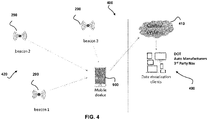
- FIG. 4 is a high-level functional schematic diagram of an embodiment of a system of acquiring and maintaining traffic apparatus location information.
- system 400 may generally comprise an array or arrangement (reference numeral 420) of traffic apparatus 100, each of which may comprise a respective beacon system 290 substantially as described above with reference to FIGS. 2 and 3 .
- each respective beacon system 290 may transmit apparatus data (such as via a respective transmitter 291) to a remote device 900 deployed in proximity to the arrangement 420.
- arrangement 420 may comprise more or fewer traffic apparatus 100 than illustrated in FIG. 4 , and that each respective traffic apparatus 100 may serve a particular function within arrangement 420.
- each respective traffic apparatus 100 may serve a particular function within arrangement 420.
- one or more "Merge Left” signs may be deployed upstream of a series of cones, delineators, or barricades that urge motorists to the left lane.
- one or more "Detour” signs may be deployed upstream of a barricade, a "Road Closed” sign, and a "Right" arrow sign urging motorists to turn right.
- the number and type of traffic apparatus 100 deployed may be application-specific and depend upon prevailing or typical traffic conditions, the nature and threat of a particular hazard, the size or length of an area affected by the traffic flow control desired, or a combination of these and a variety of other factors.
- the term "arrangement” is intended to encompass the various traffic apparatus 100 and their relative positions that, collectively, are expected to effectuate a particular traffic control goal (e.g ., closing a lane of traffic, causing traffic to turn off of a road, controlling the speed of vehicular traffic, warning of a hazard, and the like).
- remote device 900 may be configured and operative to receive apparatus data from each respective beacon system 290 while in close enough proximity to be in communication with a respective transmitter 291; this may be effectuated, for example, as a traffic apparatus 100 is being placed in arrangement 420, or it may be effectuated after all traffic apparatus 100 have been set up in desired locations. As remote device 900 is moved through arrangement 420, signal strength from each transmitter 291 may rise ( e.g., as remote device 900 approaches the associated traffic apparatus 100) and fall ( e.g., as remote device 900 recedes from the associated traffic apparatus 100).
- remote device 900 may record (or transmit) a location of that particular beacon system 291 (and thus, a location of the traffic apparatus 100 to which it is affixed) when its signal strength was at or near a maximum.
- a position for each traffic apparatus 100 in arrangement 420 may be ascertained from acquired apparatus data, recorded, and/or transmitted by remote device 900.
- Location data based upon apparatus data may be forwarded from remote device 900 to another data processing system or platform, illustrated on the right side of FIG. 4 as central system 410.
- remote device 900 may, additionally or alternatively, transmit raw apparatus data to central system 410 for processing; in such an embodiment, location data for each traffic apparatus 100 in an arrangement 420 may be derived at central system 410, for example, where processing resources and power consumption parameters may be less restricted than at remote device 900.
- derivation of location data from raw, or unprocessed, apparatus data may be implemented at remote device 900, at central system 410, or at both, operating either individually or in cooperation; these various data processing strategies may be selected in accordance with the processing capabilities and telecommunications bandwidth of remote device 900 or a variety of other factors.
- central system 410 may be embodied in or comprise a computer server or series of servers, workstations, desktop or laptop computers, or other similar data processing components useful for providing the functionality described herein.
- the various components of central system 410 (such as bus architectures, memory controllers, data storage, input/output devices, network interface cards or other telecommunications interfaces, and the like) are generally known in the art and have been omitted from FIG. 4 for clarity.
- proprietary software instruction sets may be executed, such as by central system 410, remote device 900, or a combination of both, to analyze acquired apparatus data transmitted by beacon system 290 and to write those data and the results of any computations to memory (not shown) at central system 410.
- central system 410 may acquire and maintain a detailed map recording a location of each traffic apparatus 100 deployed in a particular arrangement 420.
- location data may be aggregated with map data (available from a variety of third party navigation software providers, for instance) such that a map of a particular arrangement 420 and its constituent traffic apparatus 100 may be superimposed upon or otherwise integrated with road map data, satellite imagery data, or both.
- location data may be integrated with road map or satellite data at central system 410, which may serve or transmit aggregated data to various third party platforms 490.
- central system 410 may serve or transmit location data to third party platforms 490, which may then integrate or aggregate such location data with their own proprietary data or software applications.
- third party platforms 490 may include those owned or operated by, for example, federal, state, or local departments of transportation (DOT) or law enforcement, the National Transportation Safety Board (NTSB) or other regulatory authority, automobile manufacturers (for use in connection with onboard navigation aids or mapping software applications), suppliers of navigation software applications or solutions, and the like.
- DOT federal, state, or local departments of transportation
- NTSB National Transportation Safety Board
- central system 410 and third party platforms 490 may be via the Internet, for example, or some other wide area network, and may be wired or wireless.
- the present disclosure is not intended to be limited by the type of telecommunications technologies used by any of the parties illustrated in FIG. 4 , nor is it intended to be limited by which of the parties integrates location data with map or satellite data. Those of skill in the art will recognize that the architectural arrangement of FIG. 4 is susceptible of various alternatives and modifications.
- the road crew or a traffic control entity responsible for setting up individual traffic apparatus 100 may want to ensure, via data maintained at central system 410, for example, that a particular arrangement 420 is deployed properly, as well as when and if a traffic apparatus 100 has been moved, e.g., by wind, rain, collision, vandalism, etc.
- location data maintained at central system 410 may provide information that is useful for road crews or traffic control administrators to determine whether adjustments or relocation of one or more traffic apparatus 100 may be necessary or desirable.
- beacon system 290 may save on power such that a small photovoltaic panel or small chemical battery cell may be capable of providing sufficient power for most use cases.
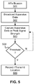
- FIG. 5 is a flow diagram illustrating aspects of a method of acquiring and maintaining traffic apparatus location information.
- a beacon such as beacon system 290
- a traffic apparatus 100 such as set forth above with reference to FIGS. 2 and 3 .
- the term "affixed” in this context is intended to be construed broadly enough to encompass embodiments in which beacon system 290 is integrated with a structural component of traffic apparatus 100, and may not require mechanical fasteners, adhesives, or other coupling elements.
- a beacon may broadcast (such as via transmitter 291, for instance) apparatus data associated with the traffic apparatus 100 to which it is affixed. As noted above, this may be accomplished utilizing data provided by one or more sensors 292 disposed on or attached to beacon system 290 as well as data provided by memory 299. Apparatus data from these sources may be combined, multiplexed, or otherwise integrated for transmission by transmitter 291, or they may be broadcast in discrete or separate data streams.
- memory 299 may store an apparatus identifier (apparatus ID) that distinguishes a traffic apparatus 100 from others that are deployed in proximity as well as a functional identifier (functional ID) that is associated with or defines the functionality of the traffic apparatus 100. Positioning, orientation, and movement or acceleration data may also be provided for real-time or near real-time system applications.
- apparatus data may be transmitted only periodically or intermittently, such as at a frequency of once every five seconds, once every ten seconds, once per minute, etc.
- beacon system 290 may comprise a transceiver device that is configured and operative to be responsive to signals from remote device 900; in such embodiments, apparatus data may be transmitted by transmitter 291, for example, responsive to requests from, or a detected proximity of, remote device 900.
- transmitter 291 for example, responsive to requests from, or a detected proximity of, remote device 900.
- Broadcast apparatus data may be captured, for example, by a remote device or instrument such as remote device 900.
- apparatus data sufficient to identify a location of traffic apparatus 100 may be captured when a signal from transmitter 291 is at peak signal strength, as measured by remote device 900 (i.e., generally, when remote device 900 is closest to beacon system 290).
- this may be effectuated by moving remote device 900 in and around an arrangement 420 of traffic apparatus 100; typically, it is expect that signal strength identified by remote device 900 will increase as remote device 900 approaches a location of traffic apparatus 100 and decrease as remote device 900 is moved away.
- Signal strength and sampling of apparatus data may continue periodically or repeatedly until a threshold low signal strength is reached, as indicated at decision block 504.
- signal strength may be above a predetermined or desired threshold, and sampling may continue; when signal strength drops below a threshold, however, remote device 900 may acknowledge loss of signal and record apparatus data at the point when signal strength was at a peak.
- remote device 900 may ascertain a location of each traffic apparatus 100, along with apparatus ID and function ID, by moving relative to the traffic apparatus 100 deployed in a particular arrangement 420; these data may be recorded ( e.g., by remote device 900 for later transmission) or simply transmitted by remote device 900 ( e.g., to central system 410) for recordation or further processing as indicated at block 599.
- location data may be derived from or informed by cellular, navigational, GPS, or other location information resident on remote device 900 and measured or computed at the time that a threshold signal strength is reached for that particular traffic apparatus 100.
- the arrangement of the blocks and the order of operations depicted in FIG. 5 are not intended to exclude other alternatives or options.
- the operations depicted at blocks 503 and 599 may occur substantially simultaneously in some implementations.
- a different type of threshold and iterative loop may be employed, and the thresholds may vary as function of the type of processing expected or desired to be carried out by remote device 900.
- a high signal strength threshold may be used instead, such that the loop is exited when signal strength begins to drop ( e.g., as remote device 900 begins to recede from traffic apparatus 100).
- a traffic control agency or other governmental or regulatory authority may ascertain and maintain the location of a portable (i.e., non-permanent) traffic apparatus 100, and may review and validate the integrity of an arrangement 420 of same, without incurring the deleterious effects of additional or onerous workflow changes.
- the foregoing system and method introduce no additional recurring fees (such as subscriptions, for example) and may be implemented at low cost (since the beacon system 290 components may be implemented simply and cheaply, with low power requirements).
- the suppliers or lessors of traffic apparatus 100 may be enabled to access location information for every traffic apparatus 100 deployed in the field, and may uniquely identify every asset's purpose and location; this may have utility in marketing, business development, and other contexts.
- Those responsible for road conditions and traveler safety may be enabled to access information sufficient to assess road conditions and to identify road closures and local hazards.
- Autonomous vehicle developers may benefit from available aggregated data by integrating apparatus data and location data into their automated control systems, increasing safety with advanced warnings of road conditions or hazard zones.
Landscapes
- Engineering & Computer Science (AREA)
- Physics & Mathematics (AREA)
- General Physics & Mathematics (AREA)
- Remote Sensing (AREA)
- Computer Networks & Wireless Communication (AREA)
- Radar, Positioning & Navigation (AREA)
- Signal Processing (AREA)
- Chemical & Material Sciences (AREA)
- Analytical Chemistry (AREA)
- Databases & Information Systems (AREA)
- Theoretical Computer Science (AREA)
- Architecture (AREA)
- Civil Engineering (AREA)
- Structural Engineering (AREA)
- Life Sciences & Earth Sciences (AREA)
- General Engineering & Computer Science (AREA)
- Data Mining & Analysis (AREA)
- Atmospheric Sciences (AREA)
- Mechanical Engineering (AREA)
- Transportation (AREA)
- Mathematical Physics (AREA)
- Automation & Control Theory (AREA)
- Traffic Control Systems (AREA)
- Mobile Radio Communication Systems (AREA)
Applications Claiming Priority (1)
| Application Number | Priority Date | Filing Date | Title |
|---|---|---|---|
| US16/059,152 US10475341B1 (en) | 2018-08-09 | 2018-08-09 | System and method of maintaining traffic apparatus location information |
Publications (3)
| Publication Number | Publication Date |
|---|---|
| EP3608892A1 true EP3608892A1 (de) | 2020-02-12 |
| EP3608892B1 EP3608892B1 (de) | 2025-05-14 |
| EP3608892C0 EP3608892C0 (de) | 2025-05-14 |
Family
ID=67587673
Family Applications (1)
| Application Number | Title | Priority Date | Filing Date |
|---|---|---|---|
| EP19191090.0A Active EP3608892B1 (de) | 2018-08-09 | 2019-08-09 | System und verfahren zur aufrechterhaltung der standortinformationen von verkehrsvorrichtungen |
Country Status (5)
| Country | Link |
|---|---|
| US (2) | US10475341B1 (de) |
| EP (1) | EP3608892B1 (de) |
| AU (2) | AU2019213445B2 (de) |
| CA (1) | CA3051421C (de) |
| GB (3) | GB2606465B (de) |
Families Citing this family (4)
| Publication number | Priority date | Publication date | Assignee | Title |
|---|---|---|---|---|
| US11380199B2 (en) * | 2018-08-09 | 2022-07-05 | Ver-Mac | System and method of maintaining traffic apparatus location information |
| US10475341B1 (en) * | 2018-08-09 | 2019-11-12 | Ver-Mac | System and method of maintaining traffic apparatus location information |
| US11153730B2 (en) * | 2019-01-31 | 2021-10-19 | Caterpillar Inc. | Systems and methods for obtaining data from machines disconnected from a network |
| GB2607855B (en) * | 2021-02-10 | 2024-07-24 | Highway Resource Solutions Ltd | A smart frame for roadworks signage |
Citations (3)
| Publication number | Priority date | Publication date | Assignee | Title |
|---|---|---|---|---|
| US20070223996A1 (en) * | 2006-03-27 | 2007-09-27 | Green Donald L | Emissive road marker system |
| US20180077521A1 (en) * | 2016-09-12 | 2018-03-15 | Industrial Scientific Corporation | Systems and methods of active beacons |
| GB2556126A (en) * | 2016-11-24 | 2018-05-23 | P F Cusack Tool Supplies Ltd | Signage unit and system incorporating a signage unit |
Family Cites Families (19)
| Publication number | Priority date | Publication date | Assignee | Title |
|---|---|---|---|---|
| US7382274B1 (en) * | 2000-01-21 | 2008-06-03 | Agere Systems Inc. | Vehicle interaction communication system |
| US7030777B1 (en) * | 2001-11-06 | 2006-04-18 | Logic Systems, Inc. | Roadway incursion alert system |
| US6864784B1 (en) * | 2002-07-19 | 2005-03-08 | Barry Loeb | Vehicle speed and safety warning system |
| US7620026B2 (en) * | 2006-10-12 | 2009-11-17 | At&T Intellectual Property I, L.P. | Methods, systems, and computer program products for providing advertising and/or information services over mobile ad hoc cooperative networks using electronic billboards and related devices |
| US20120022776A1 (en) * | 2010-06-07 | 2012-01-26 | Javad Razavilar | Method and Apparatus for Advanced Intelligent Transportation Systems |
| CA2850250C (en) * | 2011-03-07 | 2020-09-01 | Intelligent Imaging Systems, Inc. | Vehicle traffic and vehicle related transaction control system |
| US8602584B2 (en) * | 2012-03-14 | 2013-12-10 | Project Aj, Inc. | Cone light |
| US9702963B2 (en) * | 2012-05-30 | 2017-07-11 | Nokia Technologies Oy | Method, apparatus, and computer program product for high accuracy location determination |
| DE102013107658B4 (de) * | 2013-07-18 | 2016-10-13 | Matthias Borst | Warndreieck-Vorrichtung |
| WO2017072109A1 (en) * | 2015-10-27 | 2017-05-04 | Nordsense Ivs | A sign monitoring apparatus, related methods and systems |
| WO2017079842A1 (en) * | 2015-11-12 | 2017-05-18 | Fathom Systems Inc. | Apparatus, system and method of determining a location of a radio beacon |
| CN105336203A (zh) * | 2015-12-01 | 2016-02-17 | 电子科技大学 | 一种带无线发射功能的交通标志 |
| US10607467B2 (en) * | 2016-10-14 | 2020-03-31 | 3M Innovative Properties Company | Context-based programmable safety rules for personal protective equipment |
| SE540994C2 (en) * | 2016-10-27 | 2019-02-26 | Ab Blinkfyrar | Device, system and method for monitoring road sign |
| GB201716032D0 (en) * | 2017-09-30 | 2017-11-15 | Wearable Tech Limited | Attachment of an apparatus to high-visibility garments |
| CA3004651A1 (en) * | 2018-05-11 | 2018-07-17 | Technosignz Ltd. | Self-propelled autonomous message board and method |
| US10475341B1 (en) * | 2018-08-09 | 2019-11-12 | Ver-Mac | System and method of maintaining traffic apparatus location information |
| AU2021105705A4 (en) * | 2020-09-01 | 2021-10-14 | Malcolm Curtis | A garment for providing power to electric devices |
| CN113876063B (zh) * | 2021-11-18 | 2023-10-27 | 广东电网有限责任公司 | 一种多功能反光衣 |
-
2018
- 2018-08-09 US US16/059,152 patent/US10475341B1/en active Active
-
2019
- 2019-08-08 CA CA3051421A patent/CA3051421C/en active Active
- 2019-08-09 GB GB2207360.5A patent/GB2606465B/en active Active
- 2019-08-09 AU AU2019213445A patent/AU2019213445B2/en active Active
- 2019-08-09 GB GB2216525.2A patent/GB2609358B/en active Active
- 2019-08-09 EP EP19191090.0A patent/EP3608892B1/de active Active
- 2019-08-09 GB GB1911431.3A patent/GB2577969B/en active Active
- 2019-10-04 US US16/593,242 patent/US10943479B2/en active Active
-
2022
- 2022-11-07 AU AU2022268285A patent/AU2022268285B2/en active Active
Patent Citations (3)
| Publication number | Priority date | Publication date | Assignee | Title |
|---|---|---|---|---|
| US20070223996A1 (en) * | 2006-03-27 | 2007-09-27 | Green Donald L | Emissive road marker system |
| US20180077521A1 (en) * | 2016-09-12 | 2018-03-15 | Industrial Scientific Corporation | Systems and methods of active beacons |
| GB2556126A (en) * | 2016-11-24 | 2018-05-23 | P F Cusack Tool Supplies Ltd | Signage unit and system incorporating a signage unit |
Also Published As
| Publication number | Publication date |
|---|---|
| US10943479B2 (en) | 2021-03-09 |
| GB2609358A (en) | 2023-02-01 |
| GB2606465B (en) | 2023-04-26 |
| GB202216525D0 (en) | 2022-12-21 |
| CA3051421A1 (en) | 2020-02-09 |
| GB2609358B (en) | 2023-05-31 |
| AU2022268285A1 (en) | 2022-12-15 |
| US20200051433A1 (en) | 2020-02-13 |
| GB202207360D0 (en) | 2022-07-06 |
| GB2577969B (en) | 2022-07-06 |
| GB2577969A (en) | 2020-04-15 |
| AU2019213445B2 (en) | 2022-09-22 |
| CA3051421C (en) | 2025-08-05 |
| GB2606465A (en) | 2022-11-09 |
| EP3608892B1 (de) | 2025-05-14 |
| GB201911431D0 (en) | 2019-09-25 |
| AU2019213445A1 (en) | 2020-02-27 |
| EP3608892C0 (de) | 2025-05-14 |
| US10475341B1 (en) | 2019-11-12 |
| AU2022268285B2 (en) | 2024-10-24 |
Similar Documents
| Publication | Publication Date | Title |
|---|---|---|
| US11790780B2 (en) | System and method of maintaining traffic apparatus location information | |
| AU2022268285B2 (en) | System and method of maintaining traffic apparatus location information | |
| US20220030335A1 (en) | Retrofit vehicle sensor | |
| US20210237777A1 (en) | Devices and methods for channelizing vehicular traffic and enhancing workzone safety | |
| US11473737B2 (en) | Devices and methods for impact detection and associated data transmission | |
| US20130242104A1 (en) | Traffic monitoring system and method for monitoring roadway condition | |
| CA3163973C (en) | Devices and methods for impact detection and associated data transmission | |
| US9997068B2 (en) | Method for conveying driving conditions for vehicular control | |
| JP2017526576A (ja) | 無線電力及び無線通信を使用する可変画像を備える電子式車両プレートのための装置及び方法 | |
| CN102629423A (zh) | 机场滑行道碰撞报警系统 | |
| WO2018080382A1 (en) | Device, system and method for monitoring road sign | |
| US11694552B2 (en) | Traffic warning and data capture devices and methods | |
| JP6921714B2 (ja) | 安全標識追跡システム及び追跡装置 | |
| KR102029070B1 (ko) | 중앙분리대 및 가드레일에 설치되는 표시등을 통해 도로주행에 영향을 주는 교통정보를 제공하는 안전운전 지원 시스템 | |
| Ngeni et al. | Monitoring of illegal removal of road barricades using intelligent transportation systems in connected and non-connected environments | |
| CN206704072U (zh) | 一种露天矿车载监控及超速和防撞预警装置 | |
| JP7608071B2 (ja) | 事故予測装置および事故予測方法 | |
| Sintonen | Bluetooth based travel time estimation: literature review | |
| Sreevani et al. | GPS-Based Emergency Vehicle Alert System | |
| Mathew et al. | VEHICLE SAFETY AND MONITORING SYSTEM USING ARM PROCESSOR | |
| Klinkusoom et al. | Bluetooth sensors for vehicular traffic monitoring | |
| Clements et al. | Real-time traffic speeds on South African roads: the technology, applications and possibilities |
Legal Events
| Date | Code | Title | Description |
|---|---|---|---|
| PUAI | Public reference made under article 153(3) epc to a published international application that has entered the european phase |
Free format text: ORIGINAL CODE: 0009012 |
|
| STAA | Information on the status of an ep patent application or granted ep patent |
Free format text: STATUS: THE APPLICATION HAS BEEN PUBLISHED |
|
| AK | Designated contracting states |
Kind code of ref document: A1 Designated state(s): AL AT BE BG CH CY CZ DE DK EE ES FI FR GB GR HR HU IE IS IT LI LT LU LV MC MK MT NL NO PL PT RO RS SE SI SK SM TR |
|
| AX | Request for extension of the european patent |
Extension state: BA ME |
|
| STAA | Information on the status of an ep patent application or granted ep patent |
Free format text: STATUS: REQUEST FOR EXAMINATION WAS MADE |
|
| 17P | Request for examination filed |
Effective date: 20200811 |
|
| RBV | Designated contracting states (corrected) |
Designated state(s): AL AT BE BG CH CY CZ DE DK EE ES FI FR GB GR HR HU IE IS IT LI LT LU LV MC MK MT NL NO PL PT RO RS SE SI SK SM TR |
|
| STAA | Information on the status of an ep patent application or granted ep patent |
Free format text: STATUS: EXAMINATION IS IN PROGRESS |
|
| 17Q | First examination report despatched |
Effective date: 20220105 |
|
| GRAP | Despatch of communication of intention to grant a patent |
Free format text: ORIGINAL CODE: EPIDOSNIGR1 |
|
| STAA | Information on the status of an ep patent application or granted ep patent |
Free format text: STATUS: GRANT OF PATENT IS INTENDED |
|
| RIC1 | Information provided on ipc code assigned before grant |
Ipc: G08G 1/01 20060101ALN20241108BHEP Ipc: H04W 76/40 20180101ALI20241108BHEP Ipc: H04W 4/40 20180101ALI20241108BHEP Ipc: H04W 4/02 20180101ALI20241108BHEP Ipc: G01S 5/02 20100101ALI20241108BHEP Ipc: G01S 5/00 20060101ALI20241108BHEP Ipc: G01S 1/68 20060101ALI20241108BHEP Ipc: G01S 1/04 20060101ALI20241108BHEP Ipc: G08G 1/0955 20060101AFI20241108BHEP |
|
| RIC1 | Information provided on ipc code assigned before grant |
Ipc: G08G 1/01 20060101ALN20241115BHEP Ipc: H04W 76/40 20180101ALI20241115BHEP Ipc: H04W 4/40 20180101ALI20241115BHEP Ipc: H04W 4/02 20180101ALI20241115BHEP Ipc: G01S 5/02 20100101ALI20241115BHEP Ipc: G01S 5/00 20060101ALI20241115BHEP Ipc: G01S 1/68 20060101ALI20241115BHEP Ipc: G01S 1/04 20060101ALI20241115BHEP Ipc: G08G 1/0955 20060101AFI20241115BHEP |
|
| INTG | Intention to grant announced |
Effective date: 20241203 |
|
| GRAS | Grant fee paid |
Free format text: ORIGINAL CODE: EPIDOSNIGR3 |
|
| GRAA | (expected) grant |
Free format text: ORIGINAL CODE: 0009210 |
|
| STAA | Information on the status of an ep patent application or granted ep patent |
Free format text: STATUS: THE PATENT HAS BEEN GRANTED |
|
| RAP3 | Party data changed (applicant data changed or rights of an application transferred) |
Owner name: VER-MAC |
|
| AK | Designated contracting states |
Kind code of ref document: B1 Designated state(s): AL AT BE BG CH CY CZ DE DK EE ES FI FR GB GR HR HU IE IS IT LI LT LU LV MC MK MT NL NO PL PT RO RS SE SI SK SM TR |
|
| REG | Reference to a national code |
Ref country code: GB Ref legal event code: FG4D |
|
| REG | Reference to a national code |
Ref country code: CH Ref legal event code: EP |
|
| REG | Reference to a national code |
Ref country code: IE Ref legal event code: FG4D |
|
| U01 | Request for unitary effect filed |
Effective date: 20250514 |
|
| U07 | Unitary effect registered |
Designated state(s): AT BE BG DE DK EE FI FR IT LT LU LV MT NL PT RO SE SI Effective date: 20250520 |
|
| U20 | Renewal fee for the european patent with unitary effect paid |
Year of fee payment: 7 Effective date: 20250709 |
|
| PG25 | Lapsed in a contracting state [announced via postgrant information from national office to epo] |
Ref country code: ES Free format text: LAPSE BECAUSE OF FAILURE TO SUBMIT A TRANSLATION OF THE DESCRIPTION OR TO PAY THE FEE WITHIN THE PRESCRIBED TIME-LIMIT Effective date: 20250514 |
|
| PG25 | Lapsed in a contracting state [announced via postgrant information from national office to epo] |
Ref country code: GR Free format text: LAPSE BECAUSE OF FAILURE TO SUBMIT A TRANSLATION OF THE DESCRIPTION OR TO PAY THE FEE WITHIN THE PRESCRIBED TIME-LIMIT Effective date: 20250815 Ref country code: NO Free format text: LAPSE BECAUSE OF FAILURE TO SUBMIT A TRANSLATION OF THE DESCRIPTION OR TO PAY THE FEE WITHIN THE PRESCRIBED TIME-LIMIT Effective date: 20250814 |
|
| PG25 | Lapsed in a contracting state [announced via postgrant information from national office to epo] |
Ref country code: PL Free format text: LAPSE BECAUSE OF FAILURE TO SUBMIT A TRANSLATION OF THE DESCRIPTION OR TO PAY THE FEE WITHIN THE PRESCRIBED TIME-LIMIT Effective date: 20250514 |
|
| PG25 | Lapsed in a contracting state [announced via postgrant information from national office to epo] |
Ref country code: HR Free format text: LAPSE BECAUSE OF FAILURE TO SUBMIT A TRANSLATION OF THE DESCRIPTION OR TO PAY THE FEE WITHIN THE PRESCRIBED TIME-LIMIT Effective date: 20250514 |
|
| PG25 | Lapsed in a contracting state [announced via postgrant information from national office to epo] |
Ref country code: RS Free format text: LAPSE BECAUSE OF FAILURE TO SUBMIT A TRANSLATION OF THE DESCRIPTION OR TO PAY THE FEE WITHIN THE PRESCRIBED TIME-LIMIT Effective date: 20250814 |
|
| PG25 | Lapsed in a contracting state [announced via postgrant information from national office to epo] |
Ref country code: IS Free format text: LAPSE BECAUSE OF FAILURE TO SUBMIT A TRANSLATION OF THE DESCRIPTION OR TO PAY THE FEE WITHIN THE PRESCRIBED TIME-LIMIT Effective date: 20250914 |